Aircraft Structure - d24cdstip7q8pz.cloudfront.net · Load at Mid-spain Simply Supported ... While...
18
A I R C R A F T S T R U C T U R E A E
Transcript of Aircraft Structure - d24cdstip7q8pz.cloudfront.net · Load at Mid-spain Simply Supported ... While...

A
I
R
C
R
A
F
T
S
T
R
U
C
T
U
R
E
A
E

2 Career Avenues GATE Coaching by IITians
Aircraft Structure
Table of Contents
1 Aircraft
Materials &
Elasticity
Basic Aircraft Structural Elements
Axial Members
Shear Members
Bending Members
Torsion Members
Aircraft Materials and its Properties
Metals Alloys
Composites
Stresses and associated strains
Rigid Body Motion
Stress
Equilibrium Equation for non uniform Stress Variation
For 2D- Plain stress equilibrium equation
Determination of Stress in Inclined Plane under equilibrium
Tractions or total forces on any surfaces
Stress-Strain characteristics curve
Stress-Strain Relations
Strains induced by Tangential Stress
Stress Strain Relation in three dimension
Orthotropic Materials
Isotropic Materials
Poisson’s Ratio
Elastic Strain Energy
Plane Stress-strain problems
Plane Strain Problem
Plane Stress Problem
Relation between Bulk Modulus (K) and Young’s Modulus (E)
Governing Equations for elasticity problem
Equilibrium Equations
Boundary Conditions

3 Career Avenues GATE Coaching by IITians
Compatibility Equations for Plane Strain
Compatibility Equations for Plane Stress
Airy Stress Function
Mohr Circle
Equation of Mohr Circle for Stain
2 Torsion
Saint-Venant’s Principle
Torsion of arbitrary cross-section
Rods having circular cross-section
Torsion in thin sheets
Displacement along z – direction in this sheets
Torsional Constant for arbitrary thin-sections
T-section
Open curved thin sections
Torsion in thin closed arbitrary shells
Shear flow
Breth Bratho theorem
Shear Centre
Shear Centre in Open Symmetrical Section
Circular shape thin wall open section
Shear Centre of Channel-section
Multicell thin sheet closed section
3 Shear Forces and Bending
Moments
Simply supported Beam carrying a Concentrated
Load at Mid-spain
Simply Supported Beam with a Concentrated Load at arbitrary point
Simply Supported Beam carrying various Concentrated Load
Simply Supported Beam Carrying a Uniformly Distributed Load
Simply Supported Beam Subjected to a moment
Cantilever Beam having concentrated Load at its
Free End
Cantilever Beam Carrying Uniformly Distributed Load Over the Span
4 Boundary Conditions
Euler’s Theory of Buckling of Columns
Column Hinged at both Ends
Column Fixed at One End and Hinged from Other

4 Career Avenues GATE Coaching by IITians
Buckling of Vertical
Members
End
Column Fixed at Both Ends
Column Fixed at One End and Free at the Other
Limitations of Euler’s Formula
Rankin Formula
5 Beam Theory
Centroid
Moment of Inertia
Parallel Axis Theorem
Neutral Axis
Simple Bending
Pure Bending
Theory of Simple Bending
Bending Stresses
Deflection of Beam under bending
Section Modulus
Shear Forces and Shear Stress distribution
Rectangular cross-section
Rectangular section titled at 45
Circular Cross-section
I-section
For H-section
For Hollow Circular Section
For Plus Section
For Inverted Channel Section
For Triangle Section
6 Failure Theory
Maximum Principal Stress (Rankine Theory)
The Maximum Principal Strain Theory (St. Venant’s
theory)
Maximum Shear Stress theory or Guest – Columb’s Theory or Tresca’s Theory
Maximum Strain Energy Theory or Beltrami – Haigh’s Theory
Distortion Energy Theory or Von Mises Theory
7
Degree of Freedom
Natural Frequency
Classification of Vibration
Free Vibration
Forced Vibration

5 Career Avenues GATE Coaching by IITians
Theory of
Vibrations Undamped and Damped Oscillations
Linear and Non-Linear Vibrations
Deterministic and Non-Deterministic
Vibration
Spring Element
Combination of Spring
Spring in Parallel
Springs in Series
Harmonic Motion
Spring-mass system in single degree of freedom
Vibration of Un-damped System
Vibration with Viscous Damping
Critical Damping Constant and Damping Ratio
Logarithmic Decrement
Energy Stored in damper
Two degree of Freedom System
Equations of motion for Forced Vibration
Free Vibration analysis of an Undamped System
Continuous Vibration
Free vibration of Uniform string
String whose both ends are fixed
For contilever
Longitudinal Vibrations in a Bar
Common Boundary Conditions for rod in Longitudinal motion
Torsional Vibration in Beam
Response of a Damped System under Harmonic Force

6 Career Avenues GATE Coaching by IITians
CHAPTER 1
AIRCRAFT MATERIAL AND ELASTICITY
Like every industry across the world, aircraft industry also have some objective
and goals: such as to provide most economic air transport without
compromising with safety. For that, aircraft structural members needs to meet
objectives.
It should be light weighted so that payload can be high.
The material should possess high stiffness and strength so that it can
withstand high pressure loads and bending loads.
The material should be corrosion free and durable so that the aircraft
can be in service for longer time.
Some of the alloys which are being used in aircraft manufacturing are:-
Steel alloys For its ability to bear stress and it is durable.
Aluminum alloys For its light weight and high strength to weight
ratio.
Titanium alloys For its ability to withstand high stresses.
Composites For its property to withstand high temperature and
applied stresses but the drawback comes in with difficult to machine.
Composites which we normally use in Aircraft industry are carbon fiber,
glasses etc.
Nickel alloys for its ability to withstand high thermal stresses and
therefore, used for turbine blades.
While using structure aircraft, the designer know how to use material properly
for the optimization of strength to weight ratio.
Some of the requirements leads designers to use monocoque structure for
fuselage, in earlier era of aircraft development due to its promising ability of
withstanding high stresses. But time advanced, monocoque structure only are
not able to tolerate the huge fuselage design and we need the help of advanced
design and material to overcome this problem.

7 Career Avenues GATE Coaching by IITians
Basic Aircraft Structural Elements
In Aircraft Structures, major components are the assemblages of a number of
basic structural elements, which is designed to take a specific type of load such
as, axial, bending or torsional load.
Axial Members
Axial members predominantly experience tensile or compressive loads which
always acts in the axial direction. The stress so produced is uniaxial i.e,
E ... (1.1)
Where E and are young’s modulus and normal strain respectively The total
axial force:
F A EA ... (1.2)
Where A is the cross – sectional area of the member.
And ‘ EA ’ is the axial stiffness of the member which depends upon modules of
the material and cross-sectional area of the number.
Axial stiffness of axial members cannot be varied by changing the shape of
cross-section i.e. a circular rod and a channel having same cross-section which
can carry the same axial load have same stiffness.
When subjected to compressive stresses, due to high length to width ratio,
axial members are more prone to bucking failure. However it can overcome by:-
Increasing bending stiffness
By shortening the length of the buckle mode.
The higher bending stiffness is much better as it has higher bending stiffness
then the circular section. The bending stiffness of these materials is very less
due to slenderness of most axial members. The buckling strength is enhanced
by providing the lateral support along the length with more rigid ribs (in wing)
and frames (in fuselage).
8 Career Avenues GATE Coaching by IITians
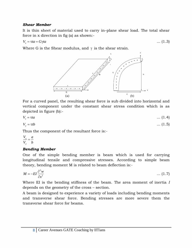
Shear Member
It is thin sheet of material used to carry in–plane shear load. The total shear
force in x direction in fig (a) as shown:-
xV ta G ta
... (1.3)
Where G is the Shear modulus, and is the shear strain.
For a curved panel, the resulting shear force is sub divided into horizontal and
vertical component under the constant shear stress condition which is as
depicted in figure (b):-
xV ta ... (1.4)
yV tb ... (1.5)
Thus the component of the resultant force is:-
x
y
V a
V b .... (1.6)
Bending Member
One of the simple bending member is beam which is used for carrying
longitudinal tensile and compressive stresses. According to simple beam
theory, bending moment M is related to beam deflection is:-
2
2
wM EI
x
... (1.7)
Where EI is the bending stiffness of the beam. The area moment of inertia I
depends on the geometry of the cross – section.
A beam is designed to experience a variety of loads including bending moments
and transverse shear force. Bending stresses are more severe them the
transverse shear force for beams.
9 Career Avenues GATE Coaching by IITians
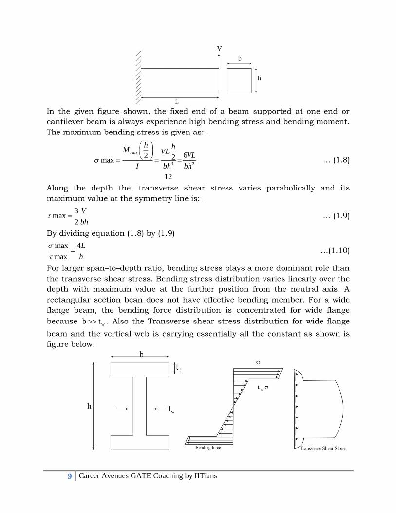
In the given figure shown, the fixed end of a beam supported at one end or
cantilever beam is always experience high bending stress and bending moment.
The maximum bending stress is given as:-
3 2
62 2max
12
max
h hM VLVL
bhI bh
… (1.8)
Along the depth the, transverse shear stress varies parabolically and its
maximum value at the symmetry line is:-
3max
2
V
bh … (1.9)
By dividing equation (1.8) by (1.9)
max 4
max
L
h
…(1.10)
For larger span–to–depth ratio, bending stress plays a more dominant role than
the transverse shear stress. Bending stress distribution varies linearly over the
depth with maximum value at the further position from the neutral axis. A
rectangular section bean does not have effective bending member. For a wide
flange beam, the bending force distribution is concentrated for wide flange
because wb t . Also the Transverse shear stress distribution for wide flange
beam and the vertical web is carrying essentially all the constant as shown is
figure below.

10 Career Avenues GATE Coaching by IITians
Torsion member
Application of shear Stress in the plane of cross – section in the production of
torque force in that plane. The torque so produced varies linearly along the
radial direction. It is related to twist angle per unit length as given by:
T Gj ... (1.11)
Where j is the torsional constant.
Aircraft Structure
Torsional Constant, J is equal to polar moment of inertia of the circular and
hollow circular cross-section of the member, therefore,
4 4 2 2 21 1
2 2pJ I b a b a b a b a ... (1.12)
where ‘GJ’ is torsional stiffness.
If the wall thickness is ‘t=b-a’ is very small as compared with the inner radius,
then j is:-
32J tr ... (1.13)
where 3 / 2r a b .
For thin walled cylinder, the torsional stiffness is proportional to the 3/2 power
of the area 2r .
The material near the inner – cavity in a thick – walled cylinder is
underutilized. It is obvious that a thin – walled tube will be more proficient for
torques than a solid cylinder and a tube. It can be found that the torsional
stiffness of the tube is almost 50 times that of the solid cylinder.

11 Career Avenues GATE Coaching by IITians
Aircraft materials and its properties
Metal Alloys
Most commonly used materials in aircraft structure are aluminum, titanium
and steel alloys. Some new jet plane, such as Boeing 787 have gained its
momentum in the field of composites that comprises of utmost 50% of their
structural weight.
Selection of aircraft material depends on many considerations which
categorized by cost or by structural performance based on structural
performance, we can categorize as,
Density (weight)
Stiffness (Young’s modulus)
Strength (Ultimate and yield Strength)
Durability (Fatigue)
Damage tolerance (fracture toughness and crack growth)
Corrosion
Combination of multiple materials as well, able to deliver all the desired
properties rather than any single material. Basic mechanical properties of some
metallic aircraft structural materials are shown in table 1.
Table 1:
Material
Property
E u Y
GPa(msi) MPa (ksi) MPa (ksi) 3 3/ /g cm lb in
Aluminium
2024-T3
7075-T6
72(10.5)
71(10.3)
0.33
0.33
449(65)
538(78)
324(47)
490(71)
2.78(0.10)
2.78(0.10
Titanium
Ti – 6Al –
4V
110(16)
0.31
925(134)
869(126)
4.46(0.16)
Steel
AlSl4340
300 M
200(29)
200(29)
0.32
0.32
1790(260)
1860(270)
1483(212)
1520(220)
7.8(0.28)
7.8(2.28)

12 Career Avenues GATE Coaching by IITians
Here u and
y are tensile ultimate stress and tensile yield stress respectively.
v is the passion’s ratio i.e. the ratio of lateral strain to longitudinal strain.
From table 1, we can se the ultimate and yield stress for titanium alloys is
almost double than that of aluminum 7075 – T6 its corrosion resistance is
superior to both aluminum and steel alloys. But aluminum is required for high
temperature application. Similar to it, Titanium is used for blades, as due to
rotation, high stress exerts on the blade, so we want high blade strength
materials and it should also be corrosion free.
Composites
For structural application we cannot use fibers in isolation. That is why to
improve its property, we can introduce fibers in same type of material matrix,
in which it can orient properly. Mechanical properties of fibers are shown in
table 2.
Table 2:
Material
Property
E u
( )GPa msi ( )GPa ksi 3/g cm
E – glass 77.0(11) 2.50(350) 2.54
S- glass 85.0(12) 3.50(500) 2.48
Silcom Carbide(Nicalom) 190.0(27) 2.80(400) 2.55
Carbon (Hercules HS4) 240.0(35) 3.60(510) 1.80
Carbon (Hercules HMS) 360(51) 2.20(310) 1.80
Carbon (Toray T300) 240.0(35) 3.50(500) 1.80
Boron 385.0(55) 3.50(500) 2.65
Kevlar – 49 (Aramid) 130.0(18) 2.80(400) 1.45
Kevlar – 29 65.0(9.5) 2.80(400) 1.45
13 Career Avenues GATE Coaching by IITians
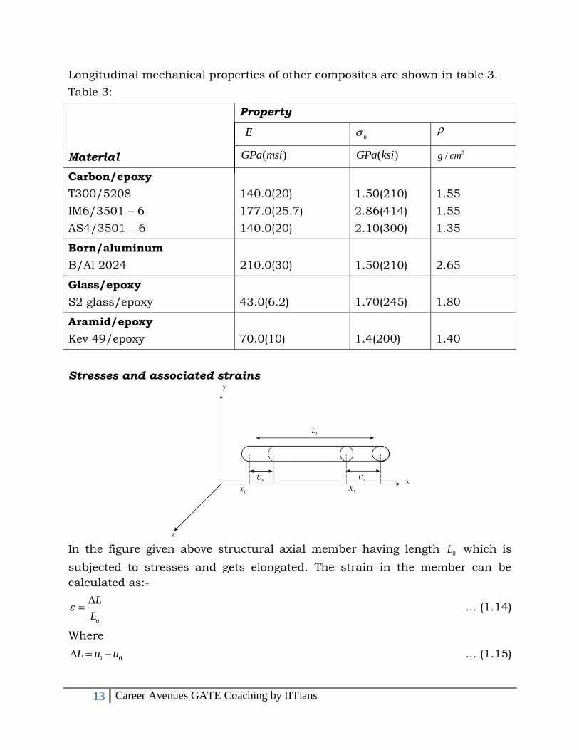
Longitudinal mechanical properties of other composites are shown in table 3.
Table 3:
Material
Property
E u
( )GPa msi ( )GPa ksi 3/g cm
Carbon/epoxy
T300/5208
IM6/3501 – 6
AS4/3501 – 6
140.0(20)
177.0(25.7)
140.0(20)
1.50(210)
2.86(414)
2.10(300)
1.55
1.55
1.35
Born/aluminum
B/Al 2024
210.0(30)
1.50(210)
2.65
Glass/epoxy
S2 glass/epoxy
43.0(6.2)
1.70(245)
1.80
Aramid/epoxy
Kev 49/epoxy
70.0(10)
1.4(200)
1.40
Stresses and associated strains
In the figure given above structural axial member having length 0L which is
subjected to stresses and gets elongated. The strain in the member can be
calculated as:-
o
L
L
... (1.14)
Where
1 0L u u ... (1.15)

14 Career Avenues GATE Coaching by IITians
Where 1 and
0 are the axial displacement component.
Strain in 1 – D case (or in axial member):-
, ,xx yy zz
u v w
x y z
... (1.16)
A 3 – D body under a complex stress system not only experience axial stresses
but also experiences shear stresses, therefore, normal strain components are
not sufficient to describe as a general state of deformation in a 3 – D body
completely. Moreover, shear strain components are also needed to describe the
distortional deformation.
Let use consider a 2 – D case
From figure above displacement may be v and u which may be positive or
negative.
Here 1
v
x
and 2
u
y
1 2xy
v u
x y
... (1.17)
similarly
yz
v w
z y
... (1.18)
and
xz
w u
x z
... (1.19)

15 Career Avenues GATE Coaching by IITians
Rigid body motion
For a rigid body motion, a body must experience a displacement without
introducing strains in the body. If the body is moved from one position to
another without getting deformed then the motion of the body cane be termed
as rigid body motion.
0
0
0
u u constant
u v constant
u w constant
... (1.20)
Represent a rigid translation motion and do not yield any strains.
Another example of a rigid body moving around in a circle. The following
displacements represent a rotation of rigid body in the x – y plane.
u y
v x
0w ... (1.21)
0, 0,xx yy
u v
x x
... (1.22)
Questions: 1.1 Consider 2a D body (a unit square’ PQRS’) in the x –y plane as
shown in figure. After deformation, the four corner points move to
A, B, C and D respectively. Assume the displacement field is
given by:
0.03u x
0.015v y
What are the total strains and the new coordinates of P, Q, R
and S.
Solution: Here
0.03xx
u
x
0.015yy
v
y

16 Career Avenues GATE Coaching by IITians
0xy
v u
x y
New position of ‘P’ after deformation
' 0.03 0 0x X
' 0.015 0 0y X
New coordinates of P which is A: (0,0)
Similarly new position of Q R and S
New coordinates of Q which is C : (1.03,1.015)
New coordinates of S Which is D: (0,1.015)
Stress
When a body is subjected to a force field, than a restoring force develops in the
body which opposes the acting force or helps the body to retain its shape. This
restoring force per unit area is termed as stress i,e:-
P
A ... (1.23)
Where A is cross – section area. If A = 1 unit area. Then P
For a 3 – D body having an area A with a unit normal vector, the stress is
defined as
0limA
Ft
A
... (1.24)
Thus, t can be considered as the force per unit area acting on the given plane
surface.
Tensile stress always acts normal to the surface whereas, shear stresses
always acts parallel to the surface.
17 Career Avenues GATE Coaching by IITians
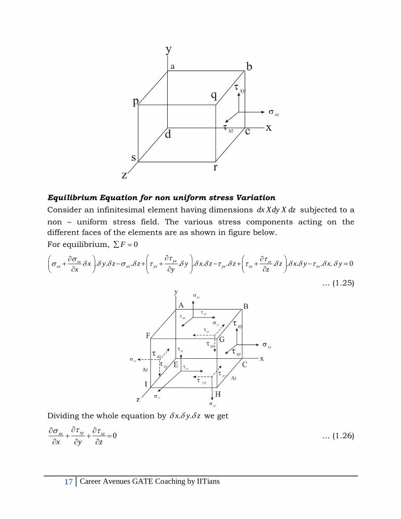
Equilibrium Equation for non uniform stress Variation
Consider an infinitesimal element having dimensions dx Xdy X dz subjected to a
non – uniform stress field. The various stress components acting on the
different faces of the elements are as shown in figure below.
For equilibrium, 0F
. . . . . . . . . . . . 0yxxx zx
xx xx yx yx zx zxx y z z y x z z z x y x yx y z
... (1.25)
Dividing the whole equation by . .x y z we get
0xyxx xz
x y z
... (1.26)
18 Career Avenues GATE Coaching by IITians
0yy yx yz
y y z
... (1.27)
0zyzxzz
z x y
... (1.28)
Above three equations are equilibrium equations about any point in a body. If a
body is said to be in equilibrium, the stress field must satisfy these equation
everywhere in the body.
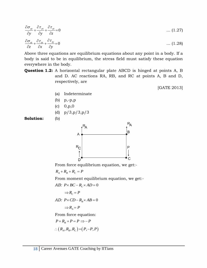
Question 1.2: A horizontal rectangular plate ABCD is hinged at points A, B
and D. AC reactions RA, RB, and RC at points A, B and D,
respectively, are
[GATE 2013]
(a) Indeterminate
(b) p,-p,p
(c) 0,p,0
(d) p/3,p/3,p/3
Solution: (b)
From force equilibrium equation, we get:-
A B CR R R P
From moment equilibrium equation, we get:-
AB: 0CP BC R AD
CR P
AD: 0BP CD R AB
AR P
From force equation:
BP R P P P
, , , ,A B CR R R P P P