Aircraft Engine Advanced Controls Research under … · at Lewis Field Glenn Research Center...
14
at Lewis Field Glenn Research Center Intelligent Control and Autonomy Branch Aircraft Engine Advanced Controls Research under NASA Aeronautics Research Mission Programs Dr. Sanjay Garg Chief, Intelligent Control and Autonomy Branch Ph: (216) 433-2685 FAX: (216) 433-8990 email: [email protected] http://www.grc.nasa.gov/WWW/cdtb 1
Transcript of Aircraft Engine Advanced Controls Research under … · at Lewis Field Glenn Research Center...

at Lewis Field
Glenn Research CenterIntelligent Control and Autonomy Branch
Aircraft Engine Advanced Controls Research under
NASA Aeronautics Research Mission Programs
Dr. Sanjay Garg
Chief, Intelligent Control and Autonomy Branch
Ph: (216) 433-2685
FAX: (216) 433-8990
email: [email protected]://www.grc.nasa.gov/WWW/cdtb
1

Aeronautics Research Mission Directorate
Advanced Air
Transport TechnologyAATT - (GRC)
Advanced Air
Vehicles (AAVP)
Airspace Operations
And Safety (AOSP)
Integrated Aviation
Systems (IASP)
NASA Aeronautics Program StructureEffective FY15
Transformative Aeronautics
Concept (TACP)
Revolutionary Vertical
Lift TechnologyRVLT - (LaRC)
Commercial Supersonic
TechnologyCST - (LaRC)
Advanced CompositesAC - (LaRC)
Aeronautics Evaluation
and Test CapabilitiesAETC - (ARMD)
Airspace Technology
DemonstrationATD - (ARC)
SMART NAS – Testbed
for Safe Trajectory
Operations (ARC)
Safe Autonomous
System OperationsSASO - (ARC)
Environmentally
Responsive
AviationERA - (LaRC)
UAS Integration
in the NAS(AFRC)
Flight Demonstration
and CapabilitiesFDC - (AFRC)
Cross Program
OperationsCPO - (ARMD)
Leading Edge
Aeronautics Research
for NASALEARN - (ARMD)
Transformational Tools
and TechnologiesTTT – (GRC)
Convergent Aeronautics
SolutionsCAS - (ARMD)
--------------------- Mission Programs ------------------- Seedling Program
2
at Lewis Field
Glenn Research CenterIntelligent Control and Autonomy Branch
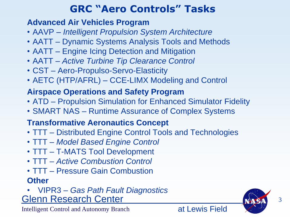
Advanced Air Vehicles Program
• AAVP – Intelligent Propulsion System Architecture
• AATT – Dynamic Systems Analysis Tools and Methods
• AATT – Engine Icing Detection and Mitigation
• AATT – Active Turbine Tip Clearance Control
• CST – Aero-Propulso-Servo-Elasticity
• AETC (HTP/AFRL) – CCE-LIMX Modeling and Control
Airspace Operations and Safety Program
• ATD – Propulsion Simulation for Enhanced Simulator Fidelity
• SMART NAS – Runtime Assurance of Complex Systems
Transformative Aeronautics Concept
• TTT – Distributed Engine Control Tools and Technologies
• TTT – Model Based Engine Control
• TTT – T-MATS Tool Development
• TTT – Active Combustion Control
• TTT – Pressure Gain Combustion
Other
• VIPR3 – Gas Path Fault Diagnostics
GRC “Aero Controls” Tasks
3
at Lewis Field
Glenn Research CenterIntelligent Control and Autonomy Branch
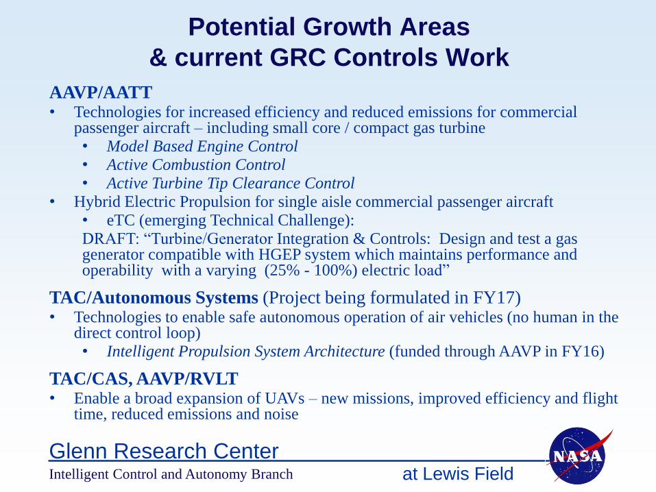
Potential Growth Areas
& current GRC Controls Work
AAVP/AATT• Technologies for increased efficiency and reduced emissions for commercial
passenger aircraft – including small core / compact gas turbine• Model Based Engine Control• Active Combustion Control• Active Turbine Tip Clearance Control
• Hybrid Electric Propulsion for single aisle commercial passenger aircraft• eTC (emerging Technical Challenge): DRAFT: “Turbine/Generator Integration & Controls: Design and test a gas generator compatible with HGEP system which maintains performance and operability with a varying (25% - 100%) electric load”
TAC/Autonomous Systems (Project being formulated in FY17)• Technologies to enable safe autonomous operation of air vehicles (no human in the
direct control loop)• Intelligent Propulsion System Architecture (funded through AAVP in FY16)
TAC/CAS, AAVP/RVLT• Enable a broad expansion of UAVs – new missions, improved efficiency and flight
time, reduced emissions and noise

at Lewis Field
Glenn Research CenterIntelligent Control and Autonomy Branch
OverviewMBEC is a significant control logic architecture technology advancement that will help realize the goals of efficiency improvements by considering controls in the design process. This technology will increase the design space available for operation due to the tighter control of margins and allow for design studies to increase efficiency
Model Based Engine Control (MBEC)P
ress
ure
Rati
o
Corrected Mass Flow
OpLine
Stall Line
Stall Margin
ConstraintLeft: Compressor performance map illustrating potential reduction in margin. Right: MBEC implementation illustrating tight control of SM and thrust to enable thrust specific fuel consumption improvements
Approach• Define the conservative margin in baseline design• Implement MBEC for a tighter control reducing
uncertainty and transient margins• Redesign engine with reduced margin and ensure safe
operation• Work with engine designers to realize efficiency
improvement

at Lewis Field
Glenn Research Center
JASC Device Drive Electronics Jansen Aircraft Systems
Controls, Inc. (JASC)SBIR Phase II
Fuel-Flow Modulator
Active Combustion Control - Fuel Modulator Development
WASK Engineering, Inc.SBIR Phase I
Prototype Model Fuel-Flow Modulator
Georgia TechFuel-Flow Modulator
Active Signal Technologies, Inc.,
Fuel-Flow Modulator
Intelligent Control and Autonomy Branch
Phase Shift
Controller
Fuel
Valve
Fuel lines, Injector
& Combustion
AcousticsNL
Flame
White Noise
++
+
Filter
Pressure from
Fuel Modulation Combustor Pressure
Instability Pressure
High Bandwidth fuel flow modulation is essential for suppression of thermo-acoustic instabilities
at Lewis Field
Glenn Research Center
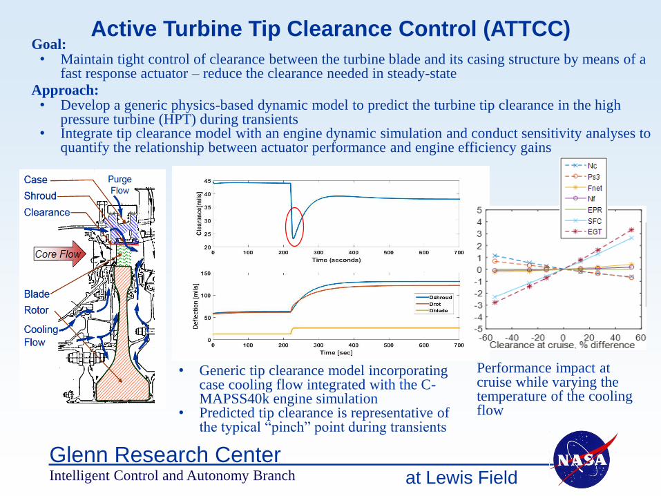
Active Turbine Tip Clearance Control (ATTCC)Goal:
• Maintain tight control of clearance between the turbine blade and its casing structure by means of a fast response actuator – reduce the clearance needed in steady-state
Approach: • Develop a generic physics-based dynamic model to predict the turbine tip clearance in the high
pressure turbine (HPT) during transients• Integrate tip clearance model with an engine dynamic simulation and conduct sensitivity analyses to
quantify the relationship between actuator performance and engine efficiency gains
Intelligent Control and Autonomy Branch
• Generic tip clearance model incorporating case cooling flow integrated with the C-MAPSS40k engine simulation
• Predicted tip clearance is representative of the typical “pinch” point during transients
Performance impact at cruise while varying the temperature of the cooling flow
at Lewis Field
Glenn Research Center
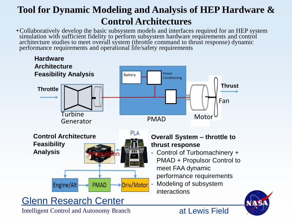
Tool for Dynamic Modeling and Analysis of HEP Hardware &
Control Architectures
Intelligent Control and Autonomy Branch
Overall System – throttle to
thrust response
- Control of Turbomachinery +
PMAD + Propulsor Control to
meet FAA dynamic
performance requirements
- Modeling of subsystem
interactions
Propulsion
Control Architecture
Feasibility
Analysis
Turbine Generator PMAD
Battery PowerConditioning
Motor
Fan
Hardware
Architecture
Feasibility Analysis
ThrottleThrust
• Collaboratively develop the basic subsystem models and interfaces required for an HEP system simulation with sufficient fidelity to perform subsystem hardware requirements and control architecture studies to meet overall system (throttle command to thrust response) dynamic performance requirements and operational life/safety requirements
at Lewis Field
Glenn Research Center
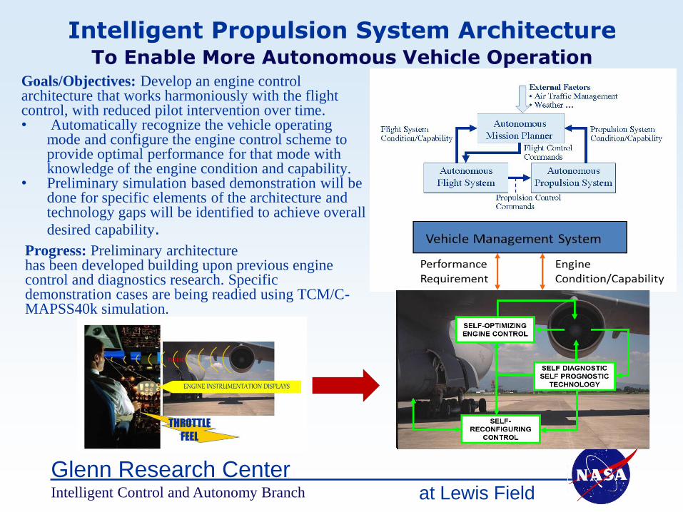
Intelligent Propulsion System ArchitectureTo Enable More Autonomous Vehicle Operation
Intelligent Control and Autonomy Branch
Goals/Objectives: Develop an engine control architecture that works harmoniously with the flight control, with reduced pilot intervention over time.• Automatically recognize the vehicle operating
mode and configure the engine control scheme to provide optimal performance for that mode with knowledge of the engine condition and capability.
• Preliminary simulation based demonstration will be done for specific elements of the architecture and technology gaps will be identified to achieve overall
desired capability.Progress: Preliminary architecturehas been developed building upon previous engine control and diagnostics research. Specific demonstration cases are being readied using TCM/C-MAPSS40k simulation.

National Aeronautics and Space Administration
www.nasa.gov
Small UAV Propulsion – Overview
Example small UAV civil
applications
• Inspection
• Photography and filming
• Spraying
• Mapping
• Weather
• Surveillance
• Delivery
• MedEvac
• Low cost flight demonstrators
NASA ARMD Vision
• The skies will accommodate thousands of times the
number of vehicles flying today
• There will be a radical increase in new and cost-
effective uses of aviation
• Autonomy will enable new types of vehicles and
missions, unconstrained by the requirements of
today’s conventional vehicles
NASA ARMD Strategy
• Enable a broad expansion of UAV applications
• Improve current configuration cost, speed, payload,
safety, and noise
• Open new markets with new configurations and
capability
Workshop Focus
• Small UAV propulsion systems in the 200 to 2,000 lbs
thrust category
• Gas turbine-based UAV propulsion systems only
o Includes turbofan, turbo-shaft, turbojet, and hybrid
electric propulsion
o Does not include battery or piston-based propulsion

at Lewis Field
Glenn Research CenterIntelligent Control and Autonomy Branch
Break-Out Sessions
• Discuss propulsion control technology development needs for:
10:00President’s Room: Turbomachinery Efficiency/Emission – Joe Connolly/Dennis Culley, Board Room: Small UAV propulsion – Don Simon1:00President’s Room: Hybrid Electric Propulsion – George Kopasakis/Joe ConnollyBoard Room: Autonomy – Jonathan Litt
• Expected Outcome:For each topic area, identify Top 2-5 Control Technology Challenges to meet the goals
For each Control Technology Challenge:
• Brief Description (what we are trying to do and why)
• Relevance to Goals
• What is the benefit – quantitative/qualitative
• Technology Development Focus and Timeframe – 5-10, 10-20, >20 years

at Lewis Field
Glenn Research CenterIntelligent Control and Autonomy Branch
Break-Out Sessions - Process
• Brief Presentation by Session Lead• Link Topic Area to Thrust(s) and Goals• Link to relevant Roadmap• Summary of current relevant work and/or plans
• Listing of potential control technology challenges to meet the Goals
• Identification of up to 5 top control technology challenges
• Discussion to complete the report out information for each identified technology area
• During the breaks, Session Leads will prepare the Report Out presentation
Questions?

at Lewis Field
Glenn Research CenterIntelligent Control and Autonomy Branch
Next Steps
• The presentations from today including the Breakout Session Reports will be made
available on the Branch website
• Link to presentations and feedback forms will be e-mailed to the attendees
• Please be sure to return the completed feedback and any additional comments
on the breakout session reports
In the next few months:
• For each topic area, using the information from the breakout session discussions,
draft roadmaps will be developed in consultation with project folks – format on
next chart
• Draft roadmap document will be shared with the attendees and feedback requested
• A paper documenting the roadmaps will be written for a future conference – either
Turbo Expo or JPC to provide an opportunity to share with broader community
• The Roadmap document will be shared with Aero project management team and
appropriate portions used to build advocacy in specific projects for future work

at Lewis Field
Glenn Research Center
Technology Challenge X – Draft Roadmap Format
• Brief Description (what we are trying to do and why)
• Relevance to Goals
• What is the benefit – quantitative/qualitative
• Technology Development Focus and Timeframe – 5-10, 10-20, >20 years
• High Level Deliverable (in the expected time frame, eg. demonstrate technology at TRL ? on aircraft/engine/lab ….)
• Intermediate Deliverables
• Advancements needed in other disciplines to achieve high level deliverables (Discipline, Technology Need)
• Potential Collaboration outside NASA
• Level of Challenge (difficulty of achieving high level goal with “reasonable” resources) – High, Medium, Low
• Level of Resources Needed – High (>$10M), Medium (<$10M > $2M) Low (<$2M)
• Mapping to most appropriate Program/Project – relevance to program/project plans