AIR-CONDITIONING AND REFRIGERATION - TechAV
92
AIR-CONDITIONING AND REFRIGERATION (ACR) Learner Guide
Transcript of AIR-CONDITIONING AND REFRIGERATION - TechAV

AIR-CONDITIONING AND
REFRIGERATION
(ACR)
Learner Guide

TABLE OF CONTENTS
ACR-1: OVERVIEW OF AIR-CONDITIONING & REFRIGERATION ABOUT THIS MODULE: ACR-1 PAGE 1 LEARNING OBJECTIVES PAGE 2 RESOURCE NOTES PART ONE: OVERVIEW OF REFRIGERATION PAGE 3 SELF-TEST EXERCISE NO. 1 PAGE 9 RESOURCE NOTES PART TWO : MECHANICAL REFRIGERATION CYCLE PAGE 11 SELF-TEST EXERCISE NO. 2 PAGE 16 RESOURCE NOTES PART THREE: ACCESSORY COMPONENTS PAGE 18 SELF-TEST EXERCISE NO. 3 PAGE 22 RESOURCE NOTES PART FOUR: SAFETY PAGE 23 SELF-TEST EXERCISE NO. 4 PAGE 25 EXTRA INFORMATION PAGE 26 TEMP / PRESSURE CHART PAGE 29 ACR-2: TUBEWORK ABOUT THIS MODULE: ACR-2 PAGE 30 LEARNING OBJECTIVE PAGE 31 RESOURCE NOTES PART ONE: TUBEWORK PAGE 32 SELF-TEST EXERCISE NO. 1 PAGE 34 RESOURCE NOTES PART TWO: HANDLING & CUTTING TUBES PAGE 35 SELF-TEST EXERCISE NO. 2 PAGE 37 RESOURCE NOTES PART THREE: FLARING PAGE 38 SELF-TEST EXERCISE NO. 3 PAGE 39 RESOURCE NOTES PART FOUR: BRAZED JOINTS PAGE 40 SELF-TEST EXERCISE NO. 4 PAGE 43 RESOURCE NOTES PART FIVE: CRIMPED WORK PAGE 44 SELF-TEST EXERCISE NO. 5 PAGE 46 RESOURCE NOTES PART SIX: BENDING OF TUBING PAGE 47 SELF-TEST EXERCISE NO. 6 PAGE 50 ACR-3: SERVICE PROCEDURES PART 1 ABOUT THIS MODULE: ACR-3 PAGE 51 LEARNING OBJECTIVE PAGE 52 RESOURCE NOTES PART ONE: GAUGE MANIFOLD PAGE 53 SELF-TEST EXERCISE NO. 1 PAGE 56 RESOURCE NOTES PART TWO: SERVICE VALVES PAGE 57 SELF-TEST EXERCISE NO. 2 PAGE 59 RESOURCE NOTES PART THREE: PRESSURE & LEAK TEST PREPARATION PAGE 61 SELF-TEST EXERCISE NO. 3 PAGE 62 RESOURCE NOTES PART FOUR: LEAK DETECTION PAGE 63 SELF-TEST EXERCISE TASK NO.4 PAGE 65 RESOURCE NOTES PART FIVE: EVACUATION PROCEDURE TOOLS / INSTRUMENTS PAGE 66 SELF-TEST EXERCISE NO. 5 PAGE 69 RESOURCE NOTES PART SIX: EVACUATION PROCEDURE PAGE 70 SELF-TEST EXERCISE NO. 6 PAGE 73

ACR-4: SERVICE PROCEDURE PART 2 ABOUT THIS MODULE: ACR-4 PAGE 74 LEARNING OBJECTIVE PAGE 75 RESOURCE NOTES PART ONE: PAGE 76 SELF-TEST EXERCISE NO. 1 PAGE 79 RESOURCE NOTES PART TWO: PAGE 80 SELF-TEST EXERCISE NO. 2 PAGE 83 RESOURCE NOTES PART THREE: PAGE 84 SELF-TEST EXERCISE NO. 3 PAGE 86 RESOURCE NOTES PART FOUR: PAGE 87 SELF-TEST EXERCISE NO. 4 PAGE 89
CONTACT DETAILS: https://techav.co.za

Table of Contents 1
ACR-1 AIR-CONDITIONING & REFRIGERATION
OBJECTIVES
o This series of basic programmes has been developed to assist you in getting started in the field of commercial air-conditioning and refrigeration. The bias of this series is toward the application of theory in practical aspects.
o This series of 4 modules will give you a practical working understanding of typical air-cooled, commercial cooling apparatus.
WHAT YOU WILL LEARN IN THIS SERIES Module 1 (ACR-1) - The fundamentals of vapour compression cooling system. Module 2 (ACR-2) - Working with copper tubing. Module 3 (ACR-3) - Service Procedures: System Evacuation. Module 4 (ACR-4) - Service Procedures: System Vapour Charge. HOW WELL YOU WILL PERFORM
o Through Self-Check Exercises you will be able to assess your performance at each stage of learning based upon Must Know or Must Do principles.
o Obtaining a YES response to the Criteria checklist. LEARNING PROCEDURE Tech A.V. has supplied you with 2 main resources namely:
o Learner Guide. o Faciitator Guide. o Video programmes (ACR).
The recommended general procedure for learning is as follows:
o Read your workbook, following any simple instruction as you read. o View the relevant video material, as given in the reading. o Practice (where applicable) performing the tasks demonstrated by the video. This is
done in your Practical Training area under the supervision of your facilitator (or Mentor / Tutor).
o Each module begins with a Learning Objective. In this way you will be clear about where the module is taking you and what you will achieve after successfully completing it.
o Resource notes provide you with valuable information. Not all information is given in the video. Certain facts (e.g. Expansion of details mentioned in the video), are given to you. Read your resource notes before viewing the video as you will obtain a clearer understanding, especially in theoretical aspects.

Table of Contents 2
LEARNING OBJECTIVE MODULE: ACR-1 OVERVIEW
OBJECTIVE Upon successful completion of this module you will be able to:
o Describe the basic theory of Heat Transfer. o Describe the effects of pressure upon liquid in terms of "saturation temperatures". o Identify and explain the function of key components of a typical commercial type
condensing unit. PROCEDURES
o Read the Resource Notes beginning on the next page. o View video ACR-1 all the way through. o View the video again but this time STOP each time you see a REVIEW section. o Complete the Self-Test Exercise that follows the relevant section in the resource
notes. o When you have mastered that section, by honestly receiving a YES response to each
criteria, then continue to the next section. RESOURCES For this module you will require:
o This workbook. o Video programme ACR-1.

Table of Contents 3
RESOURCE NOTES (PART ONE) OVERVIEW OF REFRIGERATION
INTRODUCTION Air-conditioning and refrigeration (very closely linked topics) systems operate by virtue of the fact that man has learned to apply some very basic natural laws, mainly that of Heat transfer. Knowing what is going on within a system is the foundation upon which you will build up your experience in the maintenance and diagnostics of most systems. For this reason we begin our learning by looking at some basic physics. HEAT TRANSFER Heat is a form of energy and it exists in everything. It exists in solids, liquids and gases. We cannot see heat, just as we cannot see electricity, but we all know it exists. To attempt to describe what heat is we would need to go into some very heavy science about molecules, atoms and all sorts of things which will not really help you at this time. So for practical reasons, let us just accept that heat is an energy that behaves in a predictable way.
o Heat always (no exceptions) moves between objects, substances etc, when a difference in temperature exists, and always moves from the warmer into the cooler.
NB: Temperature is NOT heat. Temperature is a measure of how warm, cool or cold something is.
o The rate or "speed" of heat transfer is increased when the temperature difference is greater.
o Heat will pass along (or through) most substances but at various rates depending upon their "thermal conductivity". Some Substances have poor thermal conductivity and are termed as "insulative". Other materials have good thermal conductivity and are simply referred to as "conductive". Most metals are good thermal conductors, whereas most fibrous-materials and plastics are good "insulative-materials".
KEEPING THINGS COOL From a refrigeration point of view we are mostly concerned about how heat can be removed from substances in order to make them / it cooler. The medium by which we cause this effect is liquid. For a simple explanation about the difference between air-conditioning and refrigeration consider this:
o Refrigeration is the process of removing heat from substance (products if you prefer!) within a closed or insulated container.
o Air-conditioning is the process of maintaining air temperature and humidity at a comfortable level for human activity.

Table of Contents 4
From the above we can see that air-conditioning may involve the removal of heat or (as in winter) the addition of heat into a room, factory, office etc. Refrigeration is simply the maintaining of coldness in substances enclosed in some form of insulated storage area. As we are mostly concerned with keeping things cool let us stay in the refrigeration scenario for purposes of easier understanding, although most of the principles also apply to air-conditioning. A SIMPLE "COOLER" DEVICE
o Keeping things cool can be a simple matter of placing a chunk of ice into a sealed (from the air) box. As long as the box is made of an insulative material (i.e. one which heat has difficulty moving through) we can maintain reasonably cool temperatures for a few hours.
o The principal is that any heat contained in the air inside the icebox will obey the natural law and move into the ice (remember heat always moves from warm temperature to cooler temperature). In effect the ice is absorbing the heat out of the air. Of course the ice itself is gaining heat, and it will eventually melt!
o Any object (e.g. your favourite cool drink, beer etc) which might be at a higher temperature than the air will lose some heat to the air. Now the air has gained some heat, which is now absorbed by the yet colder ice. A cycle of heat transfer is now going on inside your cooler.
Sooner or later all the substances will achieve a balance in temperature. The ice will gain enough heat to revert to the water state, but the beer or cool drink will have reduced its temperature from where it was to begin with. Note however that, assuming no heat entered the box, all the heat that we originally put in, is still in there! Now this arrangement is OK for a picnic, but it is not a very efficient way to maintain coldness for long periods, unless of course we have several tonnes of ice!
o Ideally we need to remove the heat out of the container and discard it in some place where it will not matter.
o A true refrigerator does exactly this, it removes heat from the container and discards that heat into the atmosphere. To appreciate how this occurs we have to go into some more basics.

Table of Contents 5
LIQUIDS AND PRESSURE
o Any substance that can flow easily and takes up a definite volume is called a liquid. The most common liquid, one that everyone knows, is water. Since all liquids behave in similar ways we shall use water as the basis of our discussion. We all know that water can be heated by placing it into a suitable container and then applying a heat source to it. (E.g. electric stove plate or gas flame.)
o Heat will move into the water because, for example, a flame has a far higher temperature than water (no matter how hot the water is).
o As heat moves into the water, the water temperature will increase, and continue to increase for as long as the heat source is applied. The heat going into the water at this time is known as sensible heat (no, not because it's clever!) because it can be sensed or seen to be causing a temperature rise if a thermometer is used to measure the temperature.
o Eventually the temperature of the whole mass of water will arrive at what is known as saturation point, (because the temperature will stop increasing) and we see the condition known as boiling.
o Any further heat added, after saturation point is reached, will be used to convert the water into its gaseous form, called vapour (sometimes called steam). The water is now in a condition which scientists call changing state. The heat energy now being absorbed by the mass of water, to maintain the change of state, is called Latent heat.
o In the change of state condition water is absorbing vast quantities of heat (latent), far more, in terms of heat quantity, than it absorbed during the sensible stage.
o Any liquid can be brought to saturation point but not necessarily will we have to heat that fluid on a stove plate in order to "boil" the liquid.
o Some liquids (mostly man made chemical compounds) reach their saturation point at a very low temperature. Ammonia for example boils at -40 degrees at standard atmospheric pressure, so how can ammonia be a liquid, you ask?
The simple answer is that it is only a liquid when it is stored in a "pressurised" state. This brings us to the pressure story:
o As most of us know, there is a pressure all around us called Atmospheric Pressure, sometimes referred to as gravity.
o Atmospheric pressure is literally the force exerted upon everything on earth caused by the shear mass (or weight) of the air which surrounds us.

Table of Contents 6
o The layer of air surrounding earth is several kilometres deep ... and we live at the bottom of this layer.
o The force or pressure that the atmosphere exerts on earth is at its greatest (for practical reasons) at sea level, where it is reckoned, on average, to be 1.03kg/ cm2.
o For most calculations, involving pressure, engineers base atmospheric pressure at 1kgcm2 or 100 kilo Pascal's at sea level. This we call "standard atmospheric pressure".
o Fresh water boils at 100 degrees Celsius at sea level in an open system, that is when the pressure acting on the water is 100 kPa (absolute). This is the theoretical value; however as atmospheric pressure changes slightly an actual temperature reading taken in boiling water may be lesser or greater at any given time.
o Many liquids will reach their "boiling-point" at far lower temperatures than water. Some liquids "boil" at temperatures lower than "ambient" (the surrounding air-temperature), and remain in liquid state only if kept at very low temperature or under "pressure".
NB: Pressure values are stated as either "gauge", or "absolute". Gauge-pressure is the value of pressure "over and above atmospheric-pressure". (i.e. the reading you see on a gauge).
Absolute-pressure is the "total pressure" acting on a substance including atmospheric pressure. Back to our water discussion:
o By increasing the pressure above water (e.g. In a closed, sealed container) we would cause the saturation point (boiling temperature) to increase.
o By decreasing the pressure above water (e.g. by reducing pressure in a sealed container) we would cause the saturation point to decrease.
o When any liquid is subjected to pressure above atmospheric-pressure it will require more sensible heat in order to achieve its saturation point.
o Conversely, less sensible heat will be required to bring a liquid, which is below atmospheric pressure to its saturation temperature.
o If pressure is reduced sufficiently it is possible to force a liquid to "boil" without the addition of a heat-source, other than the heat in the air around us (see DVD demonstration).
o In fact there is a very definite relationship between pressure and saturation points that can be plotted in a graphical form, for any given liquid type. (see example below for water).

Table of Contents 7
SOME POINTS OF FACT
o Every type of liquid has its own unique saturation point at any given pressure. o Some liquids are only able to remain in liquid state if they are subjected to pressure
(e.g. Ammonia). o Any liquid that has a saturation point below the temperature of the surrounding
(ambient temperature) will vaporise if exposed to the atmosphere. o Within a sealed container such a liquid will vaporise resulting in vapour pressure.
This self-pressurising effect is another scientific fact which we need not explain fully at this time. The fact is that vapour pressure will build up above the liquid until the equivalent saturation point is achieved.
Liquids used in refrigeration and air-conditioning systems have low saturation points. We call these liquids refrigerants. A common type is known as Refrigerant22 (or R22).
o R22, when exposed to atmospheric pressure, will instantly evaporate or vaporise. o The temperature at which R22 vaporises, at 100 kPa absolute (0 kPag) is minus 41
degrees centigrade. o Within the service-cylinder a vapour pressure of around 1100 kPag builds up when
the ambient temperature is around 30°C. o Vapour pressure, within a refrigerant cylinder, will increase with an increase of
temperature, and decrease with a decrease in temperature. In fact, simply by knowing the pressure of the vapour, we can assess the saturation temperature. (See temperature / pressure chart at back of this book).

Table of Contents 8
NOTE: Most suppliers of refrigerants offer useful temperature / pressure charts. A technician will use the chart to assess the saturation temperature of a refrigerant at the indicated gauge pressure.
SUMMARY The important things to always keep in mind are the following:
1. Heat always moves from a higher temperature to a lower temperature. 2. The greater the temperature difference, the more rapid will be the flow of heat. 3. Liquids absorb heat when changing state into their vapour form (Evaporating). 4. Vapour gives off heat when changing state into liquid from (Condensing). 5. The saturation point (boiling temperature) of a liquid is dependent upon the
pressure acting upon it. 6. Low pressure reduces the saturation point. 7. High pressure increases the saturation point.
NOW VIEW THE VIDEO UP TO REVIEW NO. 1.

Table of Contents 9
SELF-TEST EXERCISE NO. 1 INSTRUCTIONS
o Without reference to your notes or the video answer the questions below. o When you have finished, check your answers be referring to any of the resources.
QUESTIONS (complete the statements) YES NO
1. Heat is a form of ______________ that exists in all substances.
2. Heat always moves between objects / substances whenever a __________ in temperature exists, and will always move from the ______________ into the ___________ object / substance.
3. Refrigeration is the process of _____________ heat from substances within a ____________ or insulated ___________.
4. Air-conditioning is the process of maintaining _________ temperature and ____________ at a _____________ level for human activity.
5. Within a simple cooler-box a “cycle” of ____________ transfer is set up between the ___________, the __________ and the _____________ contained in objects in the box.
6. A true refrigerator _______________ heat from within a ______________ container and ____________ that heat into the _______________.
7. The heat “absorbed” to create a rise / change in the temperature of water, for example, is called _____________ heat.
8. When liquid begins to boil it is said to have reached its ____________ point.
9. Fresh water will boil at a temperature of _________ at __________ level.
10. Standard “atmosphere-pressure” is given as being ___________ kg/cm2 or ______________ kPa.
11. Liquids, including water, will reach their _____________ points at different temperatures depending upon the ______________ acting upon them.

Table of Contents 10
12. Liquids that have very low saturation points will ____________ if exposed to _____________ pressure.
13. Liquids having very low saturation points must be stored in a __________ state or condition.
14. The ____________ pressure inside a “refrigerant” cylinder ___________ until the pressure corresponds to the equivalent ______________ temperature.
15. By controlling the _____________ of refrigerant within a ____________ system we can cause it to _____________ in one area and thus absorb ______________ and to _______________ in another thus ______________ heat.

Table of Contents 11
RESOURCE NOTES (PART TWO) MECHANICAL REFRIGERATON CYCLE
INTRODUCTION In the previous section we learned about the "physics" of refrigeration. We shall now get closer to the action as we begin to learn how a typical system is put together. In this section we shall learn to identify, by name, the important devices used in a semi-hermetic air-cooled unit, so commonly encountered. A BASIC SYSTEM LAY-OUT In pure "schematic" lay-out any mechanical system has to incorporate 4 devices linked into a "closed loop" resulting in an "endless-cycle" throughout which refrigerant flows.
INDIVIDUAL ITEMS 1. COMPRESSOR

Table of Contents 12
2. CONDENSER 3. EXPANSION DEVICE 4. EVAPORATOR FUNCTION (AND PURPOSE) OF MAJOR UNITS 1. THE COMPRESSOR
This is primarily responsible for "energising" the refrigerant thus causing it to flow throughout the systems. Many types and designs of compressors are used, but all are designed to operate only with the vapour in a system (most would be damaged if liquid were to enter them). During compression heat is added to the vapour and the temperature rises significantly (in the same way as a bicycle pump gets hot during operation). The

Table of Contents 13
temperature of the vapour rises above ambient (typically to around 70-80 degrees with R22) and we now have a "temperature-differential.
2. CONDENSER The main purpose of a condenser is to discard the heat contained in the "compressed vapour". Condensers are basically metal coils, usually copper, through which the hot vapour is caused to flow. Being a good thermal conductor, copper "absorbs" much of the heat contained in the vapour as it flows through the coil. Even more heat is conducted into "fins", (normally aluminium) which are attached to the copper-tubing. A powerful fan causes a draft of air to pass over the fins. The air carries heat away from the condenser. Now back to theory! What happens to a vapour when it loses its heat? Answer: it returns to its liquid state i.e. it condenses. Condensers are designed to provide enough "surface area" for "heat transfer" to occur, and to "condense" all the vapour by the time it leaves the device. Liquid refrigerant now leaves the condenser and moves into the "liquid line". It is via the condenser that the heat "collected" by the flowing refrigerant, is discarded to the atmosphere.
3. EXPANSION DEVICE The main purpose of an expansion device is to control the amount of refrigerant passing into the evaporator. Liquid refrigerant, leaving the condenser, is at high pressure (typically around 1700 kPa, generated via the compressor). When this high-pressure liquid moves into the expansion device it is forced through a narrow restriction, or orifice. The result is a spraying effect, much like "squirting" water out of the garden hose-pipe. At this point the pressure in the liquid drops rapidly resulting in an instant "flashing" of the refrigerant. NB: Flashing is the term used to describe the "changing of state" from liquid to
vapour. (It is, in fact, a mixture of vapour and liquid that enters the evaporator.) NB: Typically the pressure would have dropped to an extent where the "saturation point" (of refrigerant) is below zero degrees.

Table of Contents 14
The heat required to cause the refrigerant to "boil" must come from where? Answer: the surroundings, or the air. This brings us to the evaporator.
4. EVAPORATOR
The primary function of an evaporator is to create a "cold" surface over which air may flow. It can be compared directly to the "block of ice" in the cooler box. Just like the condenser, an evaporator is constructed with a coil of copper tubing. Cooling fins are commonly attached to the coil, as with condensers. Refrigerant is "drawn" through the evaporator coil by the suction effect of the compressor. During its passage through the evaporator, the "evaporating liquid" is busy "absorbing heat" out of the evaporator coils and fins. Before the end of the evaporator coil, the refrigerant will have completely "vaporised". Because the "saturation point" of the refrigerant is at such a low temperature the evaporators' metal parts give up heat to satisfy the heat requirement to maintain the "boiling" condition. In turn, any heat, contained in the air surrounding the evaporator, will be drawn to the now freezing cold surfaces of the coil and fins. Many commercial evaporators utilise "air draft" fans which create an air circulation within the refrigerated space. Such a feature ensures that air is forced to flow over the evaporator. Once the refrigerant has completely vaporised it no longer absorbs heat, but it contains the heat that it collected as it passed through the evaporator. This "heat laden" vapour now flows to the compressor for "re-cycling". Although the vapour passing to the compressor does contain the heat that it collected from the refrigerated space, the temperature of the vapour will still be lower than the surrounding air. In order to cause satisfactory conditions for this heat to be "rejected" the vapour-heat temperature has to be increased to a value higher than ambient. (Remember that heat moves only from a higher temperature to a lower temperature). This brings us back to the compressor. As mentioned earlier, the vapour having been drawn into the compressor, is compressed which results in a significant temperature increase. Now that the vapour temperature has been increased we have the correct condition for heat-transfer, which occurs where? ... In the condenser. The "cycle" repeats continuously for as long as the "compressor" remains running.

Table of Contents 15
From the explanation we have seen that pressure plays an important role in the "cycle" of events. All systems comprise of two distinct pressure sections namely;
a. High-pressure side - Comprising the compressor discharge line, the condenser itself, and the "liquid-line" (i.e. from the condenser to the entry point of the expansion device).
b. A low pressure side - Comprising the outlet side of the expansion device, the evaporator and the suction-line (i.e. from the evaporator to the compressor's inlet side).
Technicians can diagnose the condition and operation of a system simply by observing or monitoring the pressures existing in both the "High Side" and the "Low Side" using "gauges" (much as a doctor can detect faults in our "human systems" by checking our blood pressure!).
NOW VIEW THE VIDEO TO REVIEW NO. 2. THEN PERFORM THE SELF-TEST EXERCISE FOR THE SECTION.

Table of Contents 16
SELF-TEST EXERCISE NO. 2 INSTRUCTIONS
o Without reference to your notes or the video answer the questions below. o When you have finished, check your answers by referring to any of the resources.
QUESTIONS YES NO
1. List by name the 4 major components of a system. i) ______________________________________________ ii) ______________________________________________ iii) ______________________________________________ iv) ______________________________________________
2. In which component is vapour compressed? ANS: _______________________________________________
3. In which component is heat absorbed? ANS: _______________________________________________
4. In which component does the pressure drop? ANS: _______________________________________________
5. In which component does vapour become liquid? ANS: _______________________________________________
6. Why is it necessary to increase the temperature of vapour before it enters the condenser? ANS: _______________________________________________ ____________________________________________________
7. Why is a fan required on a condenser? ANS: _______________________________________________ ____________________________________________________

Table of Contents 17
8. Explain in your own words, why or how, an evaporator cools? ANS: ______________________________________________ ___________________________________________________ ___________________________________________________ ___________________________________________________
9. Explain in your own words, why or how collected heat is given off to the atmosphere. ANS: ______________________________________________ ___________________________________________________ ___________________________________________________ ___________________________________________________
10. Technicians refer to the “High Side and Low Side” of a system. In your own words explain what they mean. ANS: ______________________________________________ ___________________________________________________ ___________________________________________________ ___________________________________________________

Table of Contents 18
RESOURCE NOTES (PART THREE) ACCESSORY COMPONENTS
INTRODUCTION In the previous section we described the 4 major components required in any mechanical system. These are considered essential components without which no system could operate. In this section we shall be describing some accessory components, most usually fitted to systems in order to offer either some form of "protection" or "control" over the system's operation. The system could operate without accessory devices but there would be a high risk of damage. TYPICAL ACCESSORIES 1. RECEIVERS
A receiver is basically a storage device for containing refrigerant that is not actually in circulation. It can be considered as being an excess refrigerant container.
Fluid accumulates in the receiver having been deposited there from the condenser. Although all the "flowing refrigerant" passes through the receiver a constant liquid-level is maintained during operation.
A dip-tube feeds fluid onward to the expansion device. You will rarely find a receiver featured on domestic units or where "Dome" type compressors are used.
With accessible, serviceable compressors (e.g. semi-hermetic) the receiver is required during maintenance. By manipulating service valves it is possible to force the system's refrigerant into the condenser and the reservoir and trap it there. We call this operation "pumping down". When a system has been pumped down the refrigerant in the suction side, or Low pressure-side of the system, is pumped into the High-pressure components, namely the condenser and the receiver.
The receiver therefore acts as a "reserve" container for refrigerant. 2. LIQUID-LINE SOLENOID-VALVE
This device, normally situated downstream from the receiver (but always before the drier) is a "solenoid" operated "shut-off' valve.
When the system is operating the valve is caused to open and permit a flow of refrigerant toward the

Table of Contents 19
expansion device.
When the system is in an "off-cycle" the solenoid valve closes and traps liquid in the liquid line. The valve effectively prevents liquid refrigerant from "migrating" into the evaporator when the system is not operating. If liquid refrigerant enters the evaporator it often forms a "liquid-slug" that lies in the coil. Upon start up the slug is drawn into the suction line and then into the compressor. This results in a "hydraulic" effect within the compression chamber. Serious compressor damage will result. Solenoid-valves are often incorporated into a system's "automatic-control", which will be discussed in an advanced module.
3. FILTERS AND DRIERS
Moisture is one of the basic enemies of a refrigeration system and the moisture level in any unit must be contained to an acceptable low limit. Failure to adequately reduce moisture levels will result in serious system damage, expansion valve malfunction and compressor destruction. Most refrigerants, and compressor lubricating oil, will tend to react with water (moisture) resulting in the formation of highly corrosive acids.
Moisture is always present in the air around us and any time a system has been opened some moisture will enter. Although it is possible to remove a very large proportion of moisture from a system by "vacuum evacuation methods" (see Module No.3) a small "residual" amount will always remain. To take care of this the filter-drier (or dehydrator) is used.
The filter drier offers both benefits of:
a. Absorbing small quantities of moisture. b. Trapping small particles of solids, such as soot, dust or other contaminants
that ingress a system during repairs and maintenance. Many different filter types, designs etc. are available, however most are of the "throwaway" type. It is considered a good practice to replace (renew) the filter- drier each time a system has been opened. 4. SIGHT-GLASS AND MOISTURE INDICATOR
A sight-glass / moisture indicator provides visual observation of the refrigerant flow in the liquid-line, and warns of the presence of moisture.
Although liquid refrigerant is virtually colourless it is possible to observe a "clear flow". However if bubbling or "flashing" is observed then the technician is provided with a warning that some
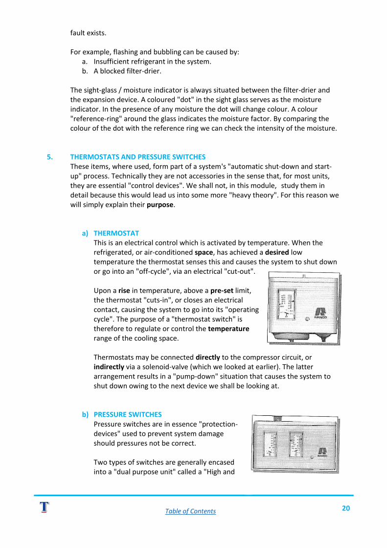
Table of Contents 20
fault exists. For example, flashing and bubbling can be caused by:
a. Insufficient refrigerant in the system. b. A blocked filter-drier.
The sight-glass / moisture indicator is always situated between the filter-drier and the expansion device. A coloured "dot" in the sight glass serves as the moisture indicator. In the presence of any moisture the dot will change colour. A colour "reference-ring" around the glass indicates the moisture factor. By comparing the colour of the dot with the reference ring we can check the intensity of the moisture.
5. THERMOSTATS AND PRESSURE SWITCHES
These items, where used, form part of a system's "automatic shut-down and start-up" process. Technically they are not accessories in the sense that, for most units, they are essential "control devices". We shall not, in this module, study them in detail because this would lead us into some more "heavy theory". For this reason we will simply explain their purpose.
a) THERMOSTAT This is an electrical control which is activated by temperature. When the refrigerated, or air-conditioned space, has achieved a desired low temperature the thermostat senses this and causes the system to shut down or go into an "off-cycle", via an electrical "cut-out".
Upon a rise in temperature, above a pre-set limit, the thermostat "cuts-in", or closes an electrical contact, causing the system to go into its "operating cycle". The purpose of a "thermostat switch" is therefore to regulate or control the temperature range of the cooling space.
Thermostats may be connected directly to the compressor circuit, or indirectly via a solenoid-valve (which we looked at earlier). The latter arrangement results in a "pump-down" situation that causes the system to shut down owing to the next device we shall be looking at.
b) PRESSURE SWITCHES Pressure switches are in essence "protection-devices" used to prevent system damage should pressures not be correct.
Two types of switches are generally encased into a "dual purpose unit" called a "High and

Table of Contents 21
Low cut-out". Should the "High Side" pressure rise to beyond a pre-set limit, the High Side sensor will cause the compressor to cut out.
Should the "Low Side" pressure fall below a pre-set limit, the Low Side sensor will also cause the compressor to cut-out. Both switches respond to "pressure signals" routed via capillary-tubes from the low and high side of the compressor's cylinder head.
NOW VIEW THE VIDEO MECHANICAL ACR-1 UP TO REVIEW NO. 3.

Table of Contents 22
SELF-TEST EXERCISE NO. 3 INSTRUCTIONS
o Without reference to your notes or the video answer the questions below. o When you have finished, check your answers by referring to any of the resources.
QUESTIONS (Complete the statements) YES NO
1. A receiver is basically a _______________ device used to contain ___________________ refrigerant that is not in ___________________.
2. A "solenoid-valve", if placed in the ___________ line, effectively prevents _______________ _____________ from migrating into the ___________________.
3. The purpose of a filter drier is to: a) ______________________________________________ b) ______________________________________________
4. If we observe bubbles or flashing in the ___________-_____________ then we know that some fault exists.
5. We can check whether a system contains ___________ by observing the _________________ of the dot in the centre of the __________________-_______________ / ___________________ ____________________
6. The main function of a "thermostat" is to control the ________________ range in the ______________ space.
7. A "dual purpose" pressure cut-out responds by cutting out the _______________ should system pressures _________________ or __________________ beyond pre-set valve.

Table of Contents 23
RESOURCE NOTES (PART FOUR) SAFETY
INTRODUCTION Like most "electro-mechanical" apparatus a refrigeration unit, or an air-conditioning unit, presents certain safety risks. The presence of electrical voltages, moving components (i.e. fans) and pressure presents a potentially unsafe condition. 1. ELECTRICAL
All safety rules / regulations applicable to electrically powered apparatus must be adhered to.
2. MOVING COMPONENTS
High-speed fans are difficult to see. Protective guards must always be in place. Do not work on fans when the refrigeration unit is LIVE. Isolate the unit from its mains supply before working on fans.
3. PRESSURE
You will often be working with substances that are stored or operate at dangerously high pressure. Always wear the recommended protective equipment to prevent injury in the case of accidental discharge. Goggles are normally considered "mandatory" for all workers handling high-pressure substances.
4. REFRIGERANTS
All refrigerants are sold or supplied in approved containers, capable of withstanding the vapour pressure created by the liquid refrigerant. Refrigerant cylinders must be stored and handled carefully. Observe the following precautions:
o Never store a cylinder in direct sunlight, nor in proximity of any source of heat (e.g. fires, space-heaters etc.)
o Never store a cylinder in any area that is likely to exceed 55°C. Dangerous vapour pressures will be generated beyond such temperature.
o Keep cylinders upright for storage purposes. o Carry cylinders carefully. Avoid knocking or dropping them. o Never open the service-valve to release refrigerant into the atmosphere. o Never deliberately allow "liquid" refrigerant to discharge to the atmosphere
or contact your skin, eyes. Severe skin and eye injury will result.
NOTE: It is illegal to deliberately discharge refrigerant into the atmosphere. When a system needs to be "emptied" the refrigerant must be "recovered or re-claimed". This process involves collecting the refrigerant and storing it in special containers (refillable cylinders), using specialised equipment. It is outside the scope of this series to venture into such processes.

Table of Contents 24
5. GASThe use of "Dry-Nitrogen" is common practice in the refrigeration repair andmaintenance field.
The pressure of stored nitrogen exceeds 15000 kPa.
A pressure regulator is mandatory when discharging this gas. The gas itself is harmless but the pressure is hazardous.
In module 3 of this series we shall be demonstrating typical usage of dry-nitrogen during an evacuation procedure.
NOW VIEW THE VIDEO MECHANICAL ACR-1 UP TO THE END.

Table of Contents 25
SELF-TEST EXERCISE NO. 4 INSTRUCTIONS
o Without reference to your notes or the video answer the questions below. o When you have finished, check your answers by referring to any of the resources.
QUESTIONS YES NO
1. List 6 safety precautions to be observed when storing and handling refrigerant containers. i) _____________________________________________ ii) _____________________________________________ iii) _____________________________________________ iv) _____________________________________________ v) _____________________________________________ vi) _____________________________________________
2. What other potentially dangerous product might you work with? ANS: _______________________________________________
3. What other equipment is considered “mandatory” when you work with pressurised substances? ANS: _______________________________________________

Table of Contents 26
EXTRA USEFUL INFORMATION 1. METRIC UNITS AND EQUIVALENTS
It is a fact that many specifications, details and data are produced in countries where the S.I. system is still being introduced (e.g. USA). The Refrigeration and Air-conditioning Industry is heavily biased toward American Standards. For this reason the technician is sometimes required to either work in or "think" in the American Standard (i.e. the Imperial system).
To assist you whenever you come across imperial data here are some useful conversions. PRESSURE
NOTE: 1 bar = 100 KN/m2 = 100kPa POWER
LENGTH

Table of Contents 27
TEMPERATURE
ABSOLUTE TEMPERATURES Rankin = ˚F + 459.6 Kelvin = °C + 273.2 THERMAL UNITS Latent heat of ice = 144Btu / Pound (lb.) = 79.92 Kilocalories / kg 1 Kcal / kg = 1.8 BTU / Ib 1 BTU / lb = 1 Kcal / kg / ˚C 1 Watt = 3.413 BTU / hr 2. REFRIGERANTS
Many types of refrigerants are in common usage around the world. Certain products have now been banned in terms of the "Montreal Protocol" which in essence is an International agreement to stop using certain products considered harmful to the environment, specifically to the ozone layer. Not all countries are signatories to the Montreal Protocol but the awareness of harmful substances in certain refrigerants is known world-wide. In common usage today, particularly in:
o Domestic refrigeration and air-conditioning. o Light commercial refrigeration and air-conditioning, and o Automotive air-conditioning.
The two most commonly encountered refrigerant types are R 134a and R22. R134a is a product which has replaced an older product called R12. R134a is most commonly used in domestic refrigeration and automotive air- conditioning. R22 is most usually used for commercial applications and air-conditioning plants. OTHER TYPES R502 is a type of refrigerant generally used for freezer applications. R717 which is ammonia. This dangerous product is used primarily in very large cold-
stores and ice-making plants. Ammonia is toxic, poisonous, flammable and explosive. It is only used with special equipment, and only very specially trained personnel may work with ammonia plants.

Table of Contents 28
3. LUBRICATING OIL All mechanical systems require lubricating oil, solely to lubricate the moving components in the compressor.
Hermetic compressors (the majority) operate in a mix of refrigerant and oil. The oil literally becomes involved in the refrigerant flow throughout the system.
It is of absolute necessity that the oil used in a system is of the type specified by the compressor manufacturer. Only "refrigerant-quality" oil may be used. Such oils have been carefully prepared to meet the operating conditions of a system.
Most types of compressor oils are "hygroscopic", meaning that they will absorb moisture (water).
NOTE: For this reason it is very important that oil containers are never allowed to be unsealed (opened) until the oil is to be added to a system. Leaving the seal (lid) off a container will rapidly render the oil useless, as it will absorb moisture from the atmosphere. If allowed into a system, "wet" oil will rapidly form harmful substances, including powerful acids that attack (corrode) metal parts.
It is rarely necessary to "top-up" oil. When a system has been correctly installed or commissioned the oil should not require any further attention.
However, oil can leak from a system where joints have not been well made, or secured. When this occurs the system would usually be "evacuated", which involves "draining" or emptying the system. The leaks are then located, repaired and the system re-charged. At this time the oil would be replenished.

Table of Contents 29
TEMPERATURE / PRESSURE CHART (Common Refrigerants)

Table of Contents 30
ACR-2 AIR-CONDITIONING & REFRIGERATION
ABOUT THIS MODULE (ACR-2) This module has been designed to assist you in acquiring the necessary skill and knowledge to perform the fundamental tasks involved in typical refrigeration tubework. The tasks demonstrated in the video material are considered to be essential skills required by anyone involved in the repair and / or servicing or air-cooled commercial-mechanical systems. This module consists of:
o This workbook. o A video programme ACR-2.
To obtain best results please read through this workbook before you view the video as this will assist you to fully understand the topics covered.

Table of Contents 31
LEARNING OBJECTIVE MODULE: ACR-2 TUBEWORK
OBJECTIVE The primary training objectives of this module are:
o Identifying refrigeration tubing. o Handling and cutting of tubing. o Making a single-flared union. o Brazing of copper tubing. o Bending of copper tubing.
PROCEDURES Using your workbook (this manual) as your guide the module becomes virtually self-explanatory. You will follow the general pattern of:
1. Read the workbook instructions. 2. Study the Resource Notes relevant to each topic. 3. View video ACR-2 for visual explanation. 4. View the video again but this time STOP each time you see a REVIEW section. 5. Perform any suggested practical exercises that follow the relevant sections. 6. Move on to the next topic after you have completed the exercise.
By following the instructions given as you read through this section you will automatically flow along and accomplish your objectives. RESOURCES To begin learning, make sure that you have access to:
o This workbook. o Video programme ACR-2.

Table of Contents 32
RESOURCE NOTES (PART ONE) TUBEWORK
INTRODUCTION
o Tubing plays a very important part in the construction of any refrigeration or air-conditioning system.
o The selection of tubing is generally decided by the designer or plant engineer, however by far the most commonly used on all plants (except in ammonia plants) is copper. Copper tubing is the first choice owing to its good thermal conductivity and ease of working.
o In this module we are going to concentrate solely on copper tubing. o The "general" term applied to tubing as used in the refrigeration industry is called
A.C.R. tubing. o Other types of tubing e.g. water tubing, steam tubing etc. are not acceptable for use
on refrigeration work. TYPES OF TUBING Two basic copper types are made for refrigeration or air-conditioning plants, namely:
1. Soft drawn copper. 2. Hard drawn copper.
SOFT DRAWN
o This type is used when bending or shaping is required. o Soft drawn is supplied in "rolled" form.
HARD DRAWN
o Used primarily where long runs are needed. o Hard drawn cannot be easily shaped or bent. o It is always supplied in standard straight lengths.
SIZING
o The size of tubing is assessed by the "outside diameter". o Most tubing is manufactured in "Imperial sizing" whereby the diameter is given in
inches or fractions of an inch. o Sizes range considerably from 1/4 inch (approximately 6 mm) up to 21/2 inches
(approximately 76 mm). o The most commonly encountered sizes in medium commercial systems are: o 1/4 inch (6 mm) 3/8 inch (10 mm) 1/2 inch (12,5 mm) 3/4 inch (19 mm).
CAPILLARY TUBING
o A special type of tubing created for applications such as: ➢ Pilot tubes to auxiliary devices such as pressure switches.

Table of Contents 33
➢ Domestic expansion device (spiral type capillary tube). o Capillary tubing is flexible but has a relatively thick wall section. The inner diameter
is small in comparison to the overall diameter.
GENERAL A.C.R. tubing is made specifically for the purpose of refrigeration and air-conditioning. It is made very carefully and has very clean, smooth inner surfaces which permit a smooth, unrestricted flow of refrigerant from component to component.
A.C.R. tubing is kept sealed during storage in order to prevent dust, dirt and moisture from entering.
NOW VIEW THE VIDEO MECHANICAL ACR-2 UP TO REVIEW NO. 1.

Table of Contents 34
SELF-TEST EXERCISE NO. 1 INSTRUCTIONS
o Without reference to your notes or any other resource, answer the questions below. o When you have finished, check your answers by referring to any of the resources.
QUESTIONS YES NO
1. What are the two basic types of copper A.C.R. tubes? a) __________________________________________________ b) __________________________________________________
2. Size is based upon what? (tick the correct answer) Outside diameter of tube? Inside diameter of tube? Tube wall thickness?
3. What do we call tubing for “pilot-tubes” and expansion-devices? ANS: _______________________________________________

Table of Contents 35
RESOURCE NOTES (PART TWO) HANDLING AND CUTTING TUBES
INTRODUCTION We begin, in this section, to handle and work with copper tubing. From the outset we must stress how important it is to prevent dirt and moisture entering the tubing. During this section you will learn some important techniques used in handling, cutting and preparing of copper tubing for use in a system. 1. HANDLING OF SOFT DRAWN TUBING Work must be carried out on a clean, flat and dry working surface.
o The roll is placed on "edge" and the free-end held firmly down on the surface.
o The roll is now "unrolled" along the work surface until the desired straight length is laid out.
o The desired length of tubing is marked for the next phase cutting.
2. CUTTING OF SOFT TUBING
A.C.R. tubing is best cut using a "wheel-type" cutting tool, commonly known as a "tube-cutter". Using a tube-cutter, like most tools, requires some practice. The video demonstrates the procedure in detail but for now remember these tips:
o Rotate in one direction only (i.e. don't "saw" the tube with back and forth motion)
o Tighten down the adjuster in small stages. o Tighten the adjuster as you maintain the turning of the tool (Le. don't stop
turning the tool whilst you adjust the wheel pressure). o Avoid over tightening which will result in:
➢ Damaging the cutter wheel. ➢ Distorting the tube.
o Maintain the cutting action until the tubing section "parts-off'.
o Seal the end of the roll when you have finished.
3. CUTTING HARD DRAWN TUBING
o The tube-cutter can also be used with this type of tubing. However more care must be exercised with the pressure applied to the cutting wheel.
o Where space is limited or where a tube cutter is unavailable, hard tubing may be cut using a hacksaw with a 32 T.P.I. blade fitted.
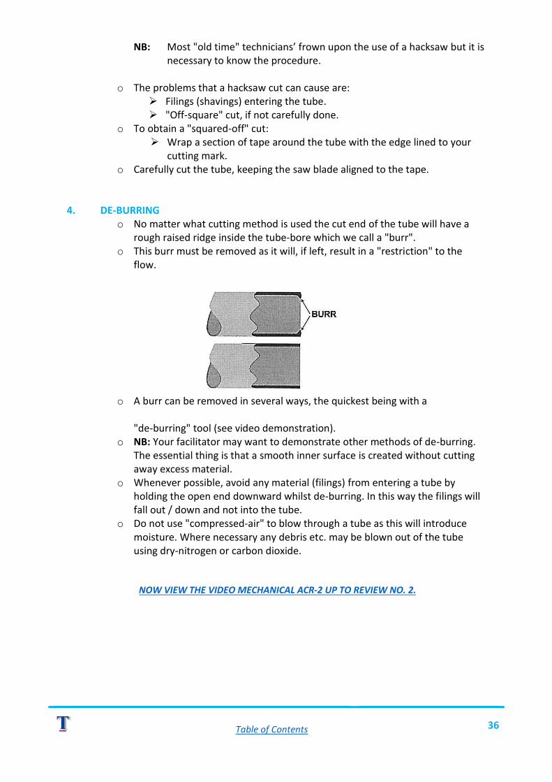
Table of Contents 36
NB: Most "old time" technicians’ frown upon the use of a hacksaw but it is necessary to know the procedure.
o The problems that a hacksaw cut can cause are:➢ Filings (shavings) entering the tube. ➢ "Off-square" cut, if not carefully done.
o To obtain a "squared-off" cut:➢ Wrap a section of tape around the tube with the edge lined to your
cutting mark. o Carefully cut the tube, keeping the saw blade aligned to the tape.
4. DE-BURRINGo No matter what cutting method is used the cut end of the tube will have a
rough raised ridge inside the tube-bore which we call a "burr".o This burr must be removed as it will, if left, result in a "restriction" to the
flow.
o A burr can be removed in several ways, the quickest being with a
"de-burring" tool (see video demonstration). o NB: Your facilitator may want to demonstrate other methods of de-burring.
The essential thing is that a smooth inner surface is created without cuttingaway excess material.
o Whenever possible, avoid any material (filings) from entering a tube byholding the open end downward whilst de-burring. In this way the filings willfall out / down and not into the tube.
o Do not use "compressed-air" to blow through a tube as this will introducemoisture. Where necessary any debris etc. may be blown out of the tubeusing dry-nitrogen or carbon dioxide.
NOW VIEW THE VIDEO MECHANICAL ACR-2 UP TO REVIEW NO. 2.

Table of Contents 37
SELF-TEST EXERCISE NO. 2 INSTRUCTIONS
o Without reference to your notes or any other sources answer the questions below. o When you have finished check your answers by referring to any of the resources. o Perform the suggested practical exercise.
QUESTIONS YES NO
1. What is very important when working with A.C.R. tubing? ANS: ______________________________________________
2. Which tool is used to make a clean neat cut on A.C.R tubing? ANS: ______________________________________________
3. What must you avoid doing to prevent damaging the cutter-wheel? ANS: ______________________________________________
4. What tool can be used to cut hard-drawn tubing? ANS: ______________________________________________
5. How do you prevent chips/debris from entering a tube? ANS: ______________________________________________
6. What effect will be caused if an internal burr is not removed? ANS: ______________________________________________
7. Why is it advisable to not use tools or grips on tubing? ANS: ______________________________________________
PRACTICAL EXERCISE Practice, in your training area, working with A.C.R. tubing doing the tasks demonstrated in the video (unrolling, cutting a section, de-burring, sealing off). Ask your Facilitator / Supervisor to assist you when necessary.

Table of Contents 38
RESOURCE NOTES (PART THREE) FLARING
INTRODUCTION It is a very common task for a technician to have to make up a section of tubing featuring a "flared-union". An important stage in the creation of such a tube is the "forming" of the "flare". A poorly made flare will invariably result in a leak, and a load of problems when the plant operates!
PROCEDURE The video section clearly demonstrates the procedure for creating an acceptable flared-end using a typical "flaring-tool". The general procedure is as follows:
o Decide upon the size of tubing required and determine the required length.o Cut the tubing using a "tube-cutter" (do not use a hacksaw with soft copper).o De-burr the ends, as previously described.o Select the appropriate hole size on the clamp bar, then clamp the tube after setting
the end to protrude slightly above the clamp-black top surface (max.3 mm).
o Select and fit the 45° flaring-cone (former) to the forcing-screw on the yolk.
NOTE: If your particular flaring tool has a "revolving" former (I.e. it rotates with the forcing screw) then you will have to apply a drop of refrigerant oil to the cone. This will reduce the friction upon the tube. In the video demonstration, the former does not rotate and that is why you see no oil used.
o Tighten the forcing screw, having positioned the yolk onto the clamp block. Do notuse excessive pressure as you force the former into the tube opening (hand force isusually sufficient).
o Remove the yolk and separate the clamp-block to remove the tube.
INSPECT THE FLARE o The flare must be free of:
➢ Splits. ➢ Wrinkles. ➢ Indentations.
o Check that the flare seats correctly:➢ Inside the flare-nut. ➢ Onto the connector nipple.
o Clean off any oil residue before connecting.
NOTE: Remember to place flare-nuts onto your tube before flaring the second end. You cannot fit flare nuts once both ends have been flared!
NOW VIEW THE VIDEO MECHANICAL ACR-2 UP TO REVIEW NO. 3.

Table of Contents 39
SELF-TEST EXERCISE NO. 3
INSTRUCTIONS
o Without reference to your notes or any other sources answer the questions below. o When you have finished check your answers by referring to any of the resources. o Perform the suggested practical exercise.
QUESTIONS YES NO
1. Label the illustration below, using the correct terminology
2. Describe the possible causes of the problems with the illustrated flares below
ANSWERS:
a)
b)
c)
PRACTICAL EXERCISE (For self-test NO. 3 of ACR-2) In your designated work area practice the skill of creating flares on soft-drawn tubing.
o Use off-cut sections for practice purposes. o Check each flare that you make by slipping a "flare-nut" over it. The nut must not
"hang-up" on the flare as it slips over the flare. o Check that the flare sits neatly onto the seat.
Have your Facilitator / Supervisor check your work.
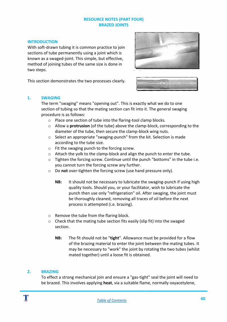
Table of Contents 40
RESOURCE NOTES (PART FOUR) BRAZED JOINTS
INTRODUCTION With soft-drawn tubing it is common practice to join sections of tube permanently using a joint which is known as a swaged-joint. This simple, but effective, method of joining tubes of the same size is done in two steps. This section demonstrates the two processes clearly. 1. SWAGING The term "swaging" means "opening out". This is exactly what we do to one section of tubing so that the mating section can fit into it. The general swaging procedure is as follows:
o Place one section of tube into the flaring-tool clamp blocks. o Allow a protrusion (of the tube) above the clamp-block, corresponding to the
diameter of the tube, then secure the clamp-block wing nuts. o Select an appropriate "swaging-punch" from the kit. Selection is made
according to the tube size. o Fit the swaging punch to the forcing screw. o Attach the yolk to the clamp-block and align the punch to enter the tube. o Tighten the forcing screw. Continue until the punch "bottoms" in the tube i.e.
you cannot turn the forcing screw any further. o Do not over-tighten the forcing screw (use hand pressure only).
NB: It should not be necessary to lubricate the swaging-punch if using high
quality tools. Should you, or your facilitator, wish to lubricate the punch then use only "refrigeration" oil. After swaging, the joint must be thoroughly cleaned, removing all traces of oil before the next process is attempted (i.e. brazing).
o Remove the tube from the flaring block. o Check that the mating tube section fits easily (slip fit) into the swaged
section.
NB: The fit should not be "tight". Allowance must be provided for a flow of the brazing material to enter the joint between the mating tubes. It may be necessary to "work" the joint by rotating the two tubes (whilst mated together) until a loose fit is obtained.
2. BRAZING To effect a strong mechanical join and ensure a "gas-tight" seal the joint will need to be brazed. This involves applying heat, via a suitable flame, normally oxyacetylene,

Table of Contents 41
and the application of a filler material. The filler material used for "copper to copper" is "copper-alloy". It should be noted that with this filler we do not require "flux".
The general process of brazing the joint is as follows:
o Assuming you are assembling the tube upon your workbench, begin by supporting the assembled tube sections between / upon suitable supports (e.g. firebricks).
o Ensure that the two sections are fully interlocked (i.e. pushed well into place). o Apply heat via a suitable heating flame to the joint. Move the flame around
the joint to ensure even heating. o When the joint begins to turn a "cherry" red colour apply the filler.
TIPS
o Copper filler will tend to flow to the hottest area. We require a "fill" between the tubes in the swage, so concentrate the heat toward the swage.
o Touch the filler-rod to the hot tubing directly on the edge of the joint. It should melt simply by contacting the metal. We do not melt the filler rod with the gas flame. The flame must be kept on the joint simply to maintain the temperature.
o The "melt" will flow readily into the joint when the temperature is correct. o Apply enough copper-filler to run around the joint. o Do not move the tube whilst the filler is still molten, this will cause crystallising and a
weak joint. o Apply, if necessary, more filler to the area where the flow has not reached. However
do not over fill. You don't want huge blobs of filler all around the outside of the joint. Remember that the objective is to fill the cavity between the joined tubes with copper-alloy, anything on the outside is simply excess and waste of material.
o Allow the joint to cool naturally. If you are in a hurry, then use a water moistened cloth to speed the cooling process but always remember not to allow moisture to enter the tube.
We have described the general procedure for creating a swaged joint. However, there are some important things we need to mention, and which you must be aware of. 1. PURGING
o The application of heat to copper in the presence of air results in "oxidising". A sooty black deposit will adhere to the copper surfaces, both on the outside and the inside surfaces.
o This "oxidation deposit" will flake off and enter the refrigerant in a system during operation.
o To prevent oxidation occurring it is standard practice to introduce a flow of inert gas, (usually dry nitrogen) through the tube, during the brazing process.

Table of Contents 42
This procedure prevents oxidising, and a shiny clean surface remains after brazing.
o In practice you will most commonly perform brazing operations upon a plantwhere the tubing is already connected. In such a situation, the system ispurged with dry nitrogen (sometimes with Carbon Dioxide) whilst the brazingprocedure is being performed.
2. JOINING DISSIMILAR METALSo The use of copper-alloy filler rod is limited to the brazing of copper to copper
only. Wherever you have to join copper tubing to any other type of metal, forexample "brass" or steel, you will have to employ other brazing methods.
o The most useful and generally used process is called "silver-soldering". Silversolder is an expensive material and your Facilitator will rarely permit you towaste this. You should learn how to use this type of filler whenever theopportunity arises.
o One thing you must be aware of is that you may never use ordinary "soft-solder" (as used in electrical or plumbing operations) to fill A.C.R. tubingjoints.
3. CLEANINGo When working with new A.C.R. copper tubing it is seldom necessary to clean
the area of tubing where a joint is to be made.o If however, you are using old or second-hand tubing, or if the tubing is
"darkened" by long exposure to the air, then a light "sanding", using fineemery-tape or "water-paper" can be done. Clean the area until a "bright"copper appearance is obtained.
o Remove all traces of oil, or grease from joint areas before you attempt thebrazing operation.
NOW VIEW THE VIDEO MECHANICAL ACR-2 UP TO REIVEW NO. 4.

Table of Contents 43
SELF-TEST EXERCISE NO. 4 INSTRUCTIONS
o Without reference to your notes or other resources answer the questions below. o When you have finished check your answers by referring to any resource. o Review the material that you did not check with a YES mark.
QUESTIONS YES NO
1. What does a “swaged-joint” allow us to make/do? ANS: ______________________________________________
2. What type of filler material is used to braze copper to copper? ANS: ______________________________________________
3. The filler-material will run / flow toward which area of the work? ANS: ______________________________________________
4. How can we prevent “oxidising” from occurring during the brazing process? ANS: ______________________________________________
5. If you have to join dissimilar metals, what process can be used? ANS: ______________________________________________
PRACTICAL EXERCISE (Suggested) In your workplace practice the skills involved in making a "swaged-joint" using soft-drawn copper tubing. Ask your facilitator to assist you in this exercise where necessary. SAFETY Do not attempt this exercise if you are not experienced with using gas heating / welding apparatus.

Table of Contents 44
RESOURCE NOTES (PART FIVE) CRIMPED WORK
INTRODUCTION Overcoming the problem of making a permanent joint between A.C.R. tubing of different sizes can be affected simply by creating a "crimped joint". There are various methods one can use to make such a joint and in the DVD we present one relatively easy method that can be performed "in-situ" (on the plant) whenever the need arises. For purposes of demonstration we illustrate the general procedure for making a joint on our workbench. However, it is simply a matter of adaptation for you to transfer the skill when working on the plant. CRIMPED JOINT (PROCEDURE)
o Assuming the joining of tubes 1/4 inch to 5/16 inch, begin by de-burring both sections once they have been cut.
o Mark the 1/4 inch tube at 20 to 25 mm from the end. o Make a similar mark on the 5/16 inch tube, also at 20 to 25 mm from the end. o Slip the 1/4 inch tube into the 5/16 inch tube until the mark aligns to the edge of the
5/16 tube. o Carefully crimp along one side of the 5/16 inch tube using flat pliers. Work along the
tube until you reach the mark on the 5/16 inch tube. o Progressively squeeze the 5/16 inch tube taking care not to squeeze the 1/4 inch
tube (this takes a little practice and skill). o Continue in this manner until the 1/4 inch tube is firmly held in the 5/16 inch tube. o Now, using "copper to copper" brazing-alloy, braze the joint as we learnt in the
previous section. SOME TIPS One of the drawbacks of crimping is the risk of creating two situations, which could cause problems in a system. Let's overview those possibilities: 1. WATER (MOISTURE TRAPS)
This can occur when a pocket is left around the inside tube, as the tube protrudes beyond the crimp (see illustration). Moisture, when present, will inevitably collect in any crevice, nook or cranny. This simply is a fact, which defies a short explanation! The reason that we mark our tubes, and crimp to the mark, is to prevent this situation.

Table of Contents 45
2. RESTRICTIONRestrictions are often caused when the filler alloy runs beyond the crimp area and enters the inner tube opening (see illustration).
As the diagram illustrates, the crimp has extended beyond the end of the inside section of tubing. Filler can now flow past the inside tube and build up, resulting in a restriction to flow. Once again, the secret is in working to your marks, and to use the minimum amount of filler to effect your joint.
NOW VIEW THE VIDEO MECHANICAL ACR-2 UP TO REVIEW NO. 5.
Table of Contents 46
SELF-TEST EXERCISE NO. 5 INSTRUCTIONS
o Without reference to your notes or other resources answer the questions below o When you have finished check your responses by referring to the resources. o Complete the practical exercise that follows the question section.
QUESTIONS YES NO
1. What is the purpose of a “crimped-joint”? ANS: ______________________________________________
2. What must we take care to prevent when we make such a joint? ANS: ______________________________________________
PRACTICAL EXERCISE (Suggested) Practice the making of "crimped-joints", as demonstrated, in your workplace. Ask your facilitator to assist you when necessary. Have your facilitator assess your work on completion.

Table of Contents 47
RESOURCE NOTES (PART SIX) BENDING OF TUBING
INTRODUCTION One of the most obvious features about any plant is the fact that seldom will a tube be without a bend somewhere. Designers strive to reduce the number of bends in connecting tubing simply because a change of direction in flow affects the rate of flow. However, certain bends (direction changes) are unavoidable and the best that can be done is to create a bend that minimises any restrictions or slowing of refrigeration flow. SOME BASIC RULES A bend must be made in such a way that:
o The inside radius of the bend is not less than five times the diameter of the tube o The tube section is always maintained in round form (i.e. no flattening or kinks). o The "ideal" bend radius is TEN times the diameter of the tube.
IDEAL R = 10 × D
MIN R = 5 × D NOTE
o Only “soft-drawn” A.C.R. copper tubing is suitable for effective bends (this includes capillary tubing).
o To effect a change in direction with “hard-drawn” tubing it is necessary to use pre-manufactured fittings or “elbows” which have to be brazed.
BENDING METHODS It is quite possible to effect a bend, with soft drawn tubing, simply with our hands. This method, however, rarely produces a "professional" looking job and, unless you have had years of practice, the tube is usually "deformed" (kinked or flattened in section). Two types of mechanical aids are commonly used to create neat and accurate bends.

Table of Contents 48
LEVER BENDER
SPRING BENDER
Both types have advantages and disadvantages. However, the Lever type bender produces the most professional and efficient bend. Lever benders are ideal for making up specific bends away from the job. Spring benders, however, are useful aids for creating "on the job" tubing, especially where the line of tube is to follow that of an existing tube. As a guide to typical usage of each type let us overview some general procedures. 1. USING A LEVER TYPE BENDER
Most lever type benders are made to suit only one of the various tube sizes available. You will therefore require one bender for each tube size that you have to deal with. To produce accurately made tube from a drawing, the general procedures are as follows:
1. Mark one end of the tube as "reference".
2. Lay tube, reference end onto lay-out, mark first bend at the centre line.

Table of Contents 49
3. Fit tube into bender, reference to left.
4. Align mark to the "L" position on lever.
5. Bend tube until zero mark comes round to 90(for right angle).
2. USING A SPRING BENDERo Select spring size, which matches tube size.o NOTE: A spring bender may be used externally
(over the tube) or internally (inside the tube).
o Bend the spring by hand, taking care to keep the bendarea within the spring. The spring acts to prevent"over-bending".
o Move the spring along the tube according to whereyou wish to create the bend.
o Remove the spring with a twisting action as you pull. This will prevent the springfrom stretching.
NOW VIEW THE VIDEO MECHANICAL ACR-2 UP TO END OF PROGRAMME.

Table of Contents 50
SELF-TEST EXERCISE NO. 6 INSTRUCTIONS
o Without reference to your notes or other resources answer the questions below. o When you have finished check your responses by referring to your resources. o Perform the suggested practical exercise after the questions.
QUESTIONS YES NO
1. WWhich type of copper tubing is suitable for bending? ANS: _________________________________________________
2. WWhat is the “ideal” radius for a bend? ANS: _________________________________________________
3. WWhat will happen if the radius is too small? ANS: _________________________________________________
4. HHow can we effect a “direction-change” with hard-drawn tubing? ANS: _________________________________________________
5. WWhich type of “bending tool” would you select to make up shaped tube from a drawing? ANS: _________________________________________________
6. WWhat is the “other type” of bender most suitable for? ANS: _________________________________________________
PRACTICAL EXERCISE (Suggested)
o Using the procedures demonstrated in the video, make up a tube that involves at least one 90 degree (right angle) bend.
o Practise creating the bend until you are able to produce a bend that aligns exactly over a "template" drawing.
o On your training model make up a tube that will follow the shape of an existing tube. o Have your facilitator assist you, where necessary, and to check your completed work.

Table of Contents 51
ACR-3 AIR-CONDITIONING &REFRIGERATION
ABOUT THIS MODULE (ACR-3) This module has been designed to assist you in acquiring the necessary skills and knowledge to perform service procedures using the tools and equipment that are fundamental to all technicians. Various tasks and procedures are demonstrated in the video (ACR-3) in order for you to be able to visualise the processes. This module consists of:
o This workbook. o A video programme ACR-3.
To obtain best results please read through this workbook before you view the video as this will assist you to fully understand the procedures we will cover.

Table of Contents 52
LEARNING OBJECTIVE MODULE: ACR-3 SERVICE PROCEDURES
OBJECTIVE The primary training objectives dealt with in this module are:
o Working with a gauge-manifold . o Working with service-valves. o Pressurising and leak detecting methods. o Evacuating moisture and air from a system.
PROCEDURES The suggested procedure for learning is as follows:
1. Read the workbook instructions. 2. Study the Resource Notes relevant to each topic. 3. View video ACR-3 for visual explanation. 4. View the video again but this time STOP each time you see a REVIEW section. 5. Perform any suggested practical exercises that follow the relevant sections. 6. Move on to the next topic after you have completed the exercise.
By following the instructions given as you read through this section you will automatically flow along and accomplish your objectives. RESOURCES To begin learning, make sure that you have access to:
o This workbook. o Video programme ACR-3.

Table of Contents 53
RESOURCE NOTES (PART ONE) SERVICE PROCEDURES 1
GAUGE MANIFOLD INTRODUCTION Of all the tools, testing devices and equipment you will be using during the time spent working with refrigeration and allied equipment, it will be your "gauge-manifold" that you will use most frequently. Your gauge manifold is extremely important and of course you will have to learn how to use it as soon as possible. In this section we look at the most common type of manifold, namely a two-control type.
THE GAUGE-MANIFOLD (Basic Features)
CONTROL OF FLOW THROUGH MANIFOLD By manipulating (opening / closing) the hand controls we may cause a flow to occur through the manifold. Depending on what function we require (e.g. simply testing pressure, or charging a system etc.) we "set" the hand controls to their relevant position. It helps to get used to operating the manifold at an early stage. The following diagrams illustrate what flow occurs in the various combinations of valve positions.

Table of Contents 54
BOTH VALVES OPEN BOTH VALVES CLOSED
LOW SIDE VALVE OPEN HIGH SIDE CLOSED
LOW SIDE VALVE CLOSED HIGH SIDE OPEN
Note that the gauges will always show a reading if pressure exists in any line. To read the actual pressure in one particular line, then close that hand control-valve. CHARGE HOSES
o In order to connect the gauge-manifold to a system (plant) we require flexible "charge-hoses" also known as "test-hoses".
o Charge-hoses are made specifically for refrigeration I air-conditioning purposes. No other type of hose may be used as the possibility of damage or injury could exist.
o Modern charge hoses are normally supplied in sets of three, each hose a different colour.
o Colour coding is now a "standard" practice throughout the industry where: ➢ Blue used on the low-pressure side. ➢ Yellow is the "common" (centre connector). ➢ Red is used on the high-pressure side.

Table of Contents 55
o In practice it is most usual to keep the charge-hoses permanently connected to thegauge-manifold. When not actually in use the free-ends are kept attached to"dummy" connectors on the back of the manifold. This prevents any dirt or moisturefrom entering a hose and reduces the risk of contaminating a system.
o Hose connections are made using hand pressure only. No tools are necessary toconnect your gauge-manifold.
NOW VIEW THE VIDEO MECHANICAL ACR-3 TO REVIEW BREAK NO. 1.

Table of Contents 56
SELF-TEST EXERCISE NO. 1 INSTRUCTIONS
o Without reference to your notes or other resources answer the questions below. o When you have finished check your responses by referring to your resources. o Complete the suggested practical exercise.
QUESTIONS YES NO
1. What colours correspond to the following? a) High pressure line. ____________________________________ b) Low pressure line. ____________________________________ c) Common line. ____________________________________
2. The "hand controls" are used to; (tick the correct response(s). a) Route the flow between ports / lines. b) Control pressure to the gauges. c) Open or close the lines in a system.
3. When not in use where should the free ends of “charge-hoses” be? ANS: ______________________________________________
4. To which gauge-port is the blue charge-hose connected on a system? ANS: ______________________________________________
5. To which gauge-port is the yellow charge hose connected? ANS: ______________________________________________
6. How are charge-hoses tightened to connections? ANS: ______________________________________________
PRACTICAL EXERCISE (Suggested) o Ask your Facilitator to show you the gauges/manifold that you will be using. o Take a look at this instrument and note its construction. o Study the gauges and learn to identify the various markings, calibrations and other
features of the gauges. o (NOTE: If you are not already familiar with how to read standard pressure gauges,
ask your facilitator to explain).

Table of Contents 57
RESOURCE NOTES (PART TWO) SERVICE PROCEDURES 1
SERVICE VALVES INTRODUCTION Service-valves are convenient devices for technicians when they are testing, charging or repairing systems. In effect a service-valve is simply a device that allows us to open, or close, a flow line in a system. The valves are generally situated close to, or directly mounted to, the compressor's suction / inlet and discharge / outlet. Sometimes a service-valve is situated on the receiver's liquid-line outlet. When positioned at the receiver the valve is known as a "King-valve". Most service-valves incorporate a gauge-port to which we connect our gauge-manifold charging-hoses.
OPERATING THE VALVE
o Service-valves are operated manually. To turn the valves' stem you will require a special tool known as a "valve-key", actually a "square-drive ratchet".
o Do not use any other tools as you will damage the stem. o Winding (turning) the stem fully inward closes off the flow through the valve. This
position is called front-seated. o Turning the stem fully outward opens the valve and permits flow. However in the
fully turned out position the "gauge-port" opening is shut-off. This position we call "back-seated".
o If we require both flow and an open gauge port then the valve stem must be neither front-seated, nor back-seated. Turning the stem to bring the valve between back-seat and front-seat position results in what we call the mid-seat position.
o Turning the stem to move the valve slightly away from either seat is called "cracking" the valve.

Table of Contents 58
o The normal position for a service-valve, during operation of a system, is BACK-seated.
o To check system pressure whilst operating, the valve is mid-seated.o To close off the suction line and the discharge line (e.g. in order to isolate the
compressor from the system) both service-valves would be FRONT-seated.
During "normal running" of a system the service-valves must be "capped" to reduce the risk of vapour loss, and to prevent dust, dirt and moisture entering. The gauge-port is capped securely with a pressure resistant cap. The valve stem is protected with a threaded cover.
SOME GENERAL MAINTENANCE TIPS (When working with Gauge Manifolds & Service-Valves)
o Wipe off any dirt, dust etc. from service-valves before you remove the caps andcovers.
o Wipe clean the valve-stem before attempting to turn the valve, thus reducing thechance of grit scoring the stem-seals.
o Make sure that the valve is back-seated before removing the gauge-port cap. Thiswill prevent loss of refrigerant to the atmosphere.
o Fit / connect your charge-hoses immediately after removing gauge-port caps. Thisreduces chance of dust, dirt and moisture entering the system.
o When finished with the task, replace caps and covers immediately to preventcontamination.
o Seal your charge-hoses immediately by connecting the free ends to the manifolddummy connections.
NOW VIEW THE VIDEO MECHANICAL ACR-3 UP TO REVIEW NO. 2.

Table of Contents 59
SELF-TEST EXERCISE NO. 2
INSTRUCTIONS o Without reference to your notes or the video answer the questions below. o Upon completion of the questions tick in the relevant column (refer to your notes /
video or facilitator for verification of an answer). o Review the material that you did not check with a YES mark.
QUESTIONS YES NO
1. A service-valve is a convenient device used to: (tick correct answer) a) isolate the compressor b) control refrigerant pressure c) regulate temperature
2. What 3 positions can we set a service-valve to? a) ______________________________________________ b) ______________________________________________ c) ______________________________________________
3. In which position is the "gauge-port" closed? ANS: ______________________________________________
4. In which position is the compressor-line closed? ANS: ______________________________________________
5. In which position do we normally set the service-valve when the system is being tested? ANS: ______________________________________________
6. In which position is the valve set for normal operation? ANS: ______________________________________________

Table of Contents 60
7. List six practical things we should do whenever we work with service-valves and charge-hoses. i) _____________________________________________ ii) _____________________________________________ iii) _____________________________________________ iv) _____________________________________________ v) _____________________________________________ vi) _____________________________________________
8. What is the only suitable tool to use for turning the service-valves' stem? ANS: ______________________________________________

Table of Contents 61
RESOURCE NOTES (PART THREE) SERVICE PROCEDURES 1
PRESSURE & LEAK TEST PREPARATION
INTRODUCTION A pre-requisite for an evaporative-compression system is that it is absolutely "gas-tight". Even the tiniest of leaks will eventually cause problems.
Having built up a system or replaced any components, tubing etc. it is "standard practice" to ensure, by testing, that no leaks exist, before the unit is charged with refrigerant.
In this section we are going to learn how to perform a pressure/leak detection test.
GENERAL PROCEDURE (Pressurise System) 1. The following items must be available:
o Refrigerant service cylinder (preferably R22).o Cylinder of dry nitrogen complete with pressure regulator.o Your gauge-manifold.o Service-valve key.o Safety goggles.
2. Connect your gauge-manifold to the system via the gauge-ports on compressorservice-valves.
3. Connect common (yellow) charge-hose to the service-cylinder discharge valve.4. Set both compressor service-valves to mid-seat position.5. Close both hand control valves on manifold.6. Switch on (if fitted) any line valves (e.g. liquid-line solenoid valve).
SAFETY: From now on you should be wearing your eye protection (goggles).
7. Open the service-cylinder valve (one full turn sufficient).8. Slowly "crack" open the low-side hand control valve at the manifold, allowing
refrigerant vapour to flow into the system.9. Close the valve as soon as the pressure on the compound gauge shows
approximately 70 kPa.10. Close the service-cylinder valve and disconnect the common line (yellow-hose).11. Connect the common line to the nitrogen cylinder regulator outlet connector.12. Set the regulator control to minimum.13. Open the nitrogen valve (main valve) slowly.14. Adjust pressure, on the "working gauge", to approximately 900 kPa (do not exceed
1200 kPa).15. Slowly open one of the manifold hand controls (it is not important which, high or low
valve).16. When gauges on manifold read that of the nitrogen gauge (working gauge), then
close off the manifold hand control.17. Shut off the main valve on the nitrogen cylinder. The system is now "standing" in
pressure and we are ready to begin checks for leaks.
NOW VIEW THE VIDEO MECHANICAL ACR-3 UP TO REVIEW NO. 3.

Table of Contents 62
SELF-TEST EXERCISE NO. 3 INSTRUCTIONS
o Without reference to your notes or the video answer the questions below. o Upon completion of the questions tick in the relevant column (refer to your notes /
video or facilitator for verification of an answer). o Review the material that you did not check with a YES mark.
QUESTIONS YES NO
1. What is the main reason for conducting a pressure and leak test? ANS: _______________________________________________
2. What gas is to be used when conducting a pressure-test? ANS: _______________________________________________
3. What type of refrigerant is normally used for leak-testing? ANS: _______________________________________________
4. What should the refrigerant pressure be limited to? (for leak test purposes.) ANS: _______________________________________________
5. What is the maximum gas pressure we should use on an air-cooled system? ANS: _______________________________________________

Table of Contents 63
RESOURCE NOTES (PART FOUR) SERVICE PROCEDURES 1
LEAK DETECTION INTRODUCTION In the last section we left our system standing in pressure. We are now going to check to see if there are leaks and how to find them. The most obvious way to see if there is a leak is to observe the pressure gauge on your manifold. A visible drop of the gauge needle would indicate that a serious leak exists. A leak of small magnitude could take hours or even days to cause a noticeable fall of the gauge needle. Further, simply by observing a gauge, we cannot tell where the leak exists. In this section we shall overview our three methods of detecting or locating leaks. 1. BUBBLE METHOD
This is as simple as it sounds. Using a soapy-liquid, such as dishwashing liquid, simply apply to each joint with a soft brush.
A leak will cause a bubble to form. This method works well if the following conditions exist:
o There is no wind around. o You can reach the joint. o The leak is "strong" enough to form a bubble.
(In other words, it is not a very accurate method.)
2. ELECTRONIC DETECTOR-METHOD Moving from the primitive to the "space-age" a more accurate method of detection is with a highly sensitive "electronic-detector". This device "senses" refrigerant vapour, even in very small amounts.
A "sensing-probe" is passed slowly along the systems tube-work, over the fittings and all components.
As soon as the sensor picks up even a trace of vapour (refrigerant) an audio signal is given off, or on some models, indicator lights will flash.
Many types are available and each will have certain features and operating methods specifically for that unit. Always study the manufacturer's instruction manual before using a unit which is unfamiliar.

Table of Contents 64
3. "HALIDE-TORCH" DETECTION METHODA "halide-torch" detects any gas (vapour) which contains chlorine. A small gasflame burns beneath a copper ring in the torch head. A rubber-tube, called the"sniffer-tube", connects to the head beneath the flame.
An air draft passes up the rubber tube, caused by the uprising of warm air around the flame.
The sniffer-tube is passed slowly over the joints, tubing and other parts of a refrigeration / air-conditioning system.
If a vapour leak exists, the vapour is drawn up the tube and passes over the hot copper ring. This results in a reaction which causes the flame to change colour.
A normal flame is yellow. In the presence of a small amount of chlorine the flame will become green. In the presence of a large quantity of chlorine the flame will become blue (or violet) in colour.
Halide-testers will not operate where "chlorine-free" refrigerants are used, such as R134a.
NOTE: Refrigerant 22 is the ideal vapour for use when performing a halide leak detection test on a "newly" assembled system.
GENERAL o When a leak has been located, mark the joint or area for identification purposes.o Electronic detectors are highly sensitive instruments and will detect any vapour even
if it is lurking in the room. For this reason the work area should be well ventilatedand all sources of vapour (e.g. service cylinders etc.) should be moved away from theplant.
o At the opposite extreme, too much "draught" will tend to make for difficultdetection.
o When any or all leaks have been located, detected and marked then those leaksmust be dealt with.
CORRECTING LEAKS o Leaks at "threaded connections" are most usually fixed simply by firmly securing the
flare unit. If tightening does not cure a leak then check the flare for cracks.o Leaks at "brazed" joints will require further brazing.o Always "open" the system when brazing a tube in-situ.o Purge dry-nitrogen through the system during the brazing process.o Protect adjacent components (around the brazing area) from heat damage using
suitable "heat sinking". In most cases a wet cloth will be sufficient.
NOW VIEW THE VIDEO MECHANICAL ACR-3 UP TO REVIEW NO. 4.

Table of Contents 65
SELF-TEST EXERCISE NO. 4 INSTRUCTIONS
o Without reference to your notes or the video answer the questions below. o Upon completion of the questions tick in the relevant column (refer to your notes /
video or your facilitator for verification of an answer). o Review the material that you did not check with a YES mark.
QUESTIONS YES NO
1. What is the most obvious way to see if a major leak exists? ANS: _______________________________________________
2. What method of leak-detection could be used if you have no special equipment? ANS: _______________________________________________
3. What devices can be used to detect small leaks where R-22 is used? ANS: _______________________________________________
4. What device is used to detect leaks when the system uses R-134a? ANS: _______________________________________________
5. When a leak has been located, what do you do first? ANS: _______________________________________________
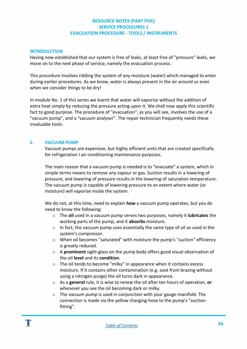
Table of Contents 66
RESOURCE NOTES (PART FIVE) SERVICE PROCEDURES 1
EVACUATION PROCEDURE - TOOLS / INSTRUMENTS INTRODUCTION Having now established that our system is free of leaks, at least free of "pressure" leaks, we move on to the next phase of service, namely the evacuation process. This procedure involves ridding the system of any moisture (water) which managed to enter during earlier procedures. As we know, water is always present in the air around us even when we consider things to be dry! In module No. 1 of this series we learnt that water will vaporise without the addition of extra heat simply by reducing the pressure acting upon it. We shall now apply this scientific fact to good purpose. The procedure of "evacuation", as you will see, involves the use of a "vacuum pump", and a "vacuum analyser". The repair technician frequently needs these invaluable tools: 1. VACUUM PUMP
Vacuum pumps are expensive, but highly efficient units that are created specifically for refrigeration I air-conditioning maintenance purposes.
The main reason that a vacuum pump is needed is to "evacuate" a system, which in simple terms means to remove any vapour or gas. Suction results in a lowering of pressure, and lowering of pressure results in the lowering of saturation temperature. The vacuum pump is capable of lowering pressure to an extent where water (or moisture) will vaporise inside the system.
We do not, at this time, need to explain how a vacuum pump operates, but you do need to know the following:
o The oil used in a vacuum pump serves two purposes, namely it lubricates the working parts of the pump, and it absorbs moisture.
o In fact, the vacuum pump uses essentially the same type of oil as used in the system's compressor.
o When oil becomes "saturated" with moisture the pump's "suction" efficiency is greatly reduced.
o A prominent sight-glass on the pump body offers good visual observation of the oil level and its condition.
o The oil tends to become "milky" in appearance when it contains excess moisture. If it contains other contamination (e.g. soot from brazing without using a nitrogen purge) the oil turns dark in appearance.
o As a general rule, it is wise to renew the oil after ten hours of operation, or whenever you see the oil becoming dark or milky.
o The vacuum pump is used in conjunction with your gauge-manifold. The connection is made via the yellow charging-hose to the pump's "suction-fitting".

Table of Contents 67
o Control of the suction (vacuum effect) is always made with your manifold hand control valves.
o A vacuum pump is always started up and switched off against a closed manifold.
2. VACUUM ANALYSER
o Typical vacuum analysers are "electronic vacuum sensing devices", or if you prefer, very accurate "vacuum gauges".
o The compound gauge on your gauge-manifold is not an accurate instrument when it operates in the "vacuum" zone. At best it is an "indication" that vacuum conditions exist.
o NOTE: At this time we must assume that you are familiar with "pressure" and "vacuum" terms.
o Electronic instruments offer displayed readings in terms of absolute pressure. o NOTE: Atmospheric pressure is stated as 760 millimetres or mercury (760
mm.Hg) absolute. A perfect vacuum is O mm.Hg. This figure is unachievable outside of a scientific laboratory!
o When dealing with very low pressures, those much below atmospheric, we usually express figures in MICRONS. A micron (symbol Il) is one, one-thousandth of a millimetre. Standard atmospheric pressure, expressed in microns, is 760,0001l.
o Typically a good vacuum pump could reduce the pressure within a system to around 500 microns. At this low pressure water will achieve its saturation point at -24°C.
o Returning to the vacuum analyser; a sensor-lead containing an electronic sensing device (thermistor or transducer) is connected physically, via a coupling, into the system.
o A convenient attachment position is the gauge-port on the receiver's "King-valve". Alternatively a "tee-connector" can be fitted anywhere in the system, such as at the vacuum pump suction-line.

Table of Contents 68
NOTE: Always become familiar with the "operating instructions" supplied by the instrument's manufacturer. Beware: some sensing devices may be damaged by exposure to normal system pressure, meaning that they cannot be connected until the system is de-pressurised".
o Typical procedures for connecting both the vacuum pump and the vacuumanalyser are demonstrated in the DVD.
NOW VIEW THE VIDEO MECHANICAL ACR-3 UP TO REVIEW NO. 6.

Table of Contents 69
SELF-TEST EXERCISE NO. 5 INSTRUCTIONS
o Without reference to your notes or the video answer the questions below. o Upon completion of the questions tick in the relevant column (refer to your notes /
video or your facilitator for verification of an answer). o Review the material that you did not check with a YES mark.
QUESTIONS YES NO
1. What is the purpose of a vacuum pump? ANS: ______________________________________________
2. What is the purpose of a vacuum-analyser? ANS: ______________________________________________
3. What important checks must be made before we use a vacuum pump? ANS: ______________________________________________
4. Before starting or stopping the vacuum pump what should we do first? ANS: ______________________________________________
5. Before using a vacuum-analyser for the first time, what should you do? ANS: ______________________________________________

Table of Contents 70
RESOURCE NOTES (PART SIX) SERVICE PROCEDURES 1
EVACUATION PROCEDURE INTRODUCTION Now that you are familiar with the instruments and equipment that we need, let us get on with the evacuation procedure. We must mention a couple of things first:
o The "pulling" of a vacuum does not necessarily mean that all moisture will be "sucked out" of the system. The "deeper" the vacuum the less will be the out-flow of vapour and air-molecules from the system.
o Leaving a vacuum pump to run for hours, even days, is both time-consuming and largely ineffective.
o Evacuation is always a relatively slow process but using the "triple evacuation" method, as we shall demonstrate, does offer an effective and relatively quick way to ensure a "dry" system.
o There is no need to flush the system with refrigerant, as was the case in days gone by. Today we cannot afford to waste refrigerant, and the law prohibits the dumping of such products into the atmosphere.
TRIPLE EVACUATION
1. With both hand controls (gauge manifold) closed, start up the vacuum pump. 2. Slowly open either, or preferably both, of the hand control valves.
NB: The compressor service-valves are mid-seated. 3. When the compound gauge indicates that "vacuum" exists, we can then operate the
vacuum analyser. 4. The vacuum is "pulled" initially to approximately 5mmHg(5000 microns). 5. At this time, close the hand control valves at the manifold and then switch off the
vacuum pump. 6. Now, disconnect the common charge-hose from the vacuum pump and connect it to
the nitrogen cylinder regulator. 7. Adjust the "working pressure" to ±. 60 kPag at the regulator. (NB: If your vacuum
analyser is "pressure sensitive" then disconnect it, or isolate it during the next stage). 8. Open the low (or high) hand control "allowing" nitrogen to flow into the system and
reach the pressure of 60 kPa. 9. Allow the system to "stand" for approximately one hour. During this time the
nitrogen will be absorbing water vapour inside the full system. 10. After the elapsed time, reconnect the common charge hose to the vacuum pump.
Start the pump and open the manifold control valve. 11. Pull a second vacuum to 5 mmHg (5000 microns). At this time much of the vapour
will flow out with the nitrogen via the pump. 12. Repeat steps 8, 9 and 10. 13. Finally, pull down the vacuum (i.e. on the third pull) to 500 microns, or as far as the
pump can go. This could take some length of time.

Table of Contents 71
14. When the lowest possible vacuum is achieved, or you have achieved 500 microns, close (both) hand control valves and shut off the vacuum pump.
15. Observe the behaviour of the analyser for the first 6 -10 minutes. The procedure is shown below in the "flow-chart" sequence.
CONCLUSION "Analyse" the behaviour of the vacuum:
1. The pressure may rise slightly within the first 30 seconds to around 1000 microns. This is a normal scenario.
2. If the pressure thereafter remains constant for at least 7 minutes, then our system is "tight" and "dry". This is our desired aim.
3. If the pressure climbs to around 2000 microns over a minute or two and then stays steady for several minutes ... then our system is "gas-tight" but contains some moisture.
4. If the pressure continues to rise steadily then there is a leak in the system. If situation no. 3 exists, you will have to continue with evacuation. If situation no. 4 exists, you will have to perform a complete pressure and leak detection procedure and then repeat the evacuation process.

Table of Contents 73
SELF-TEST EXERCISE NO. 6 INSTRUCTIONS
o Without reference to your notes or the video answer the questions below. o Upon completion of the questions tick in the relevant column (refer to your notes /
video or your facilitator for verification of an answer). o Review the material that you did not check with a YES mark.
QUESTIONS YES NO
1. Fill in the “process flow-chart” for a triple-evacuation procedure.

Table of Contents 74
ACR-4 AIR-CONDITIONING & REFRIGERATION
ABOUT THIS MODULE (ACR-4) This module has been designed to assist you in acquiring the necessary skill and knowledge to perform a vapour charge procedure to an air-cooled, semi-hermetic refrigeration unit. Various tasks and procedures are demonstrated in the video (ACR-4) that will help you understand and perform the tasks. NOTE: This module is in effect a continuation of Module 3 (ACR-3) and should be studied
only when you have successfully completed ACR-3. This module consists of:
o This workbook. o A video programme ACR-4.
To obtain best results please read through this workbook before you view the video, as this will assist you to fully understand the procedures we will cover.

Table of Contents 75
LEARNING OBJECTIVE MODULE: ACR-4 SERVICE PROCEDURES PART 2
OBJECTIVE The primary training objectives dealt with in this module are:
o Describing optimum charge. o Performing a vapour charge. o Explaining basic operating checks / maintenance.
PROCEDURES Using your workbook (this manual) as your guide the module follows the procedure of:
1. Read the workbook instructions. 2. Study the Resource Notes relevant to each topic. 3. View video ACR-4 for visual explanation. 4. View the video again but this time STOP each time you see a REVIEW section. 5. Perform the relevant self-test exercise. 6. Move on to the next topic after you have completed the exercise.
By following the instructions given as you read through this section you will automatically flow along and accomplish your objectives. RESOURCES To begin learning, make sure that you have access to:
o This workbook. o Video programme ACR-4.

Table of Contents 76
RESOURCE NOTES (PART ONE) SERVICE PROCEDURES 2
OPTIMUM CHARGE INTRODUCTION In the previous module we prepared our system to receive the charge of refrigerant. This involved making sure that the system was "gas-tight" and moisture free. In this module we are going to complete our unit assembly with a vapour-charge and running check procedure. Before we launch into practical procedures it is important for you to understand certain facts that will assist us in reaching our objective of "achieving an optimum-charge". WHAT IS AN OPTIMUM-CHARGE? The simple answer to this question is that an optimum-charge is when a system contains enough refrigerant, in terms of volume or mass, to satisfy the load conditions. To help illustrate it is useful to understand what happens in a system when either of two unsatisfactory conditions exist, namely an overcharge condition and an undercharge condition. OVERCHARGE Obviously, as the term implies, an overcharge is where an excess charge of refrigerant exists in a system. This problem is rarely encountered on systems that have receivers because the receiver tends to act as a "buffer" against overcharge. For purposes of illustration we will examine a system that has no receiver (as is the case in most domestic units).
The system on the previous page has been overcharged. The purpose of the expansion device is to feed the evaporator with a flow-rate of liquid refrigerant that is equal to the evaporation rate (i.e. a liquid flow-rate which matches the load of the moment). In other

Table of Contents 77
words, the expansion device will permit any excess refrigerant to pass through it. Excess fluid will join the queue upstream of the expansion device, which means that it is going to back up in the condenser. This will reduce the available condenser surface area and the condenser will effectively become too small for the duty. The result of pumping more gas than the condenser wants to handle is for the discharge pressure to rise. High discharge pressure therefore is a sign of an overcharged system. High discharge pressure can also be a sign of other things, for example, a dirty condenser, air in the system or, very high "ambient" temperature. If you look at the diagram you will see that, in an over-charged condition, the condenser contains too much liquid. This liquid will become considerably sub cooled as the air draught removes heat. Excessive sub-cooling, coupled with high discharge pressure is another important indicator of an overcharged system. High discharge pressure results in the compressor drive-motor having to work a lot harder, and draw more current. This condition can be checked using a tong-tester (ammeter). If the amperage is higher than stated on the motor name-plate, (max. operating amperage) then an overcharge condition could be the problem. UNDERCHARGE In this situation there is not enough refrigerant present in the system to form a liquid seal at the condenser outlet. This means a mixture of gas and liquid enters the expansion device. An expansion device sized, for example, to pass 70 grams per second of liquid won’t be capable of passing a 70 grams per second mixture of liquid and vapour. (A given mass of vapour is far larger than the same mass of liquid. The mixture will simply choke the expansion device). The compressor, in its turn, will also have been sized to pump 70 grams per second of suction vapour, at the design suction pressure. (Shall we say at 425 kPa?) Feed it with less refrigerant, and its larger capacity related to that of the evaporator right now will cause suction pressure to drop. So, signs of an undercharged system are low capacity and low suction pressure. Other possibilities of low capacity and low suction pressure include:
o Dirty evaporator. o Iced evaporator surfaces. o Evaporator fan malfunction (low air-
flow). o Oil hanging up in the evaporator. o Choked expansion device (caused by
moisture icing or wax deposits from oil).

Table of Contents 78
CORRECTLY CHARGED SYSTEM The liquid line, under all operating conditions should be completely filled with liquid. No vapour must be present.
When the system is correctly charged, just enough liquid will back up into the outlet of the condenser to form the all-important liquid seal.
Under good operating conditions, the liquid in the liquid line will be slightly sub-cooled.
We shall describe sub-cooling later in this module.
NOW VIEW THE VIDEO MECHANICAL ACR-4 UP TO REVIEW NO. 1.

Table of Contents 79
SELF-TEST EXERCISE NO. 1 INSTRUCTIONS
o Without reference to your notes or the video answer the questions below. o When you have finished, check your answers by referring to any of the resources.
QUESTIONS YES NO
1. What are 2 signs of an “over-charged” system? a) _________________________________________________ b) __________________________________________________
2. What is the most noticeable sign of an “undercharged” system? ANS: _______________________________________________
3. Which of the two above situations is less likely to occur in a system that features a receiver? ANS: _______________________________________________
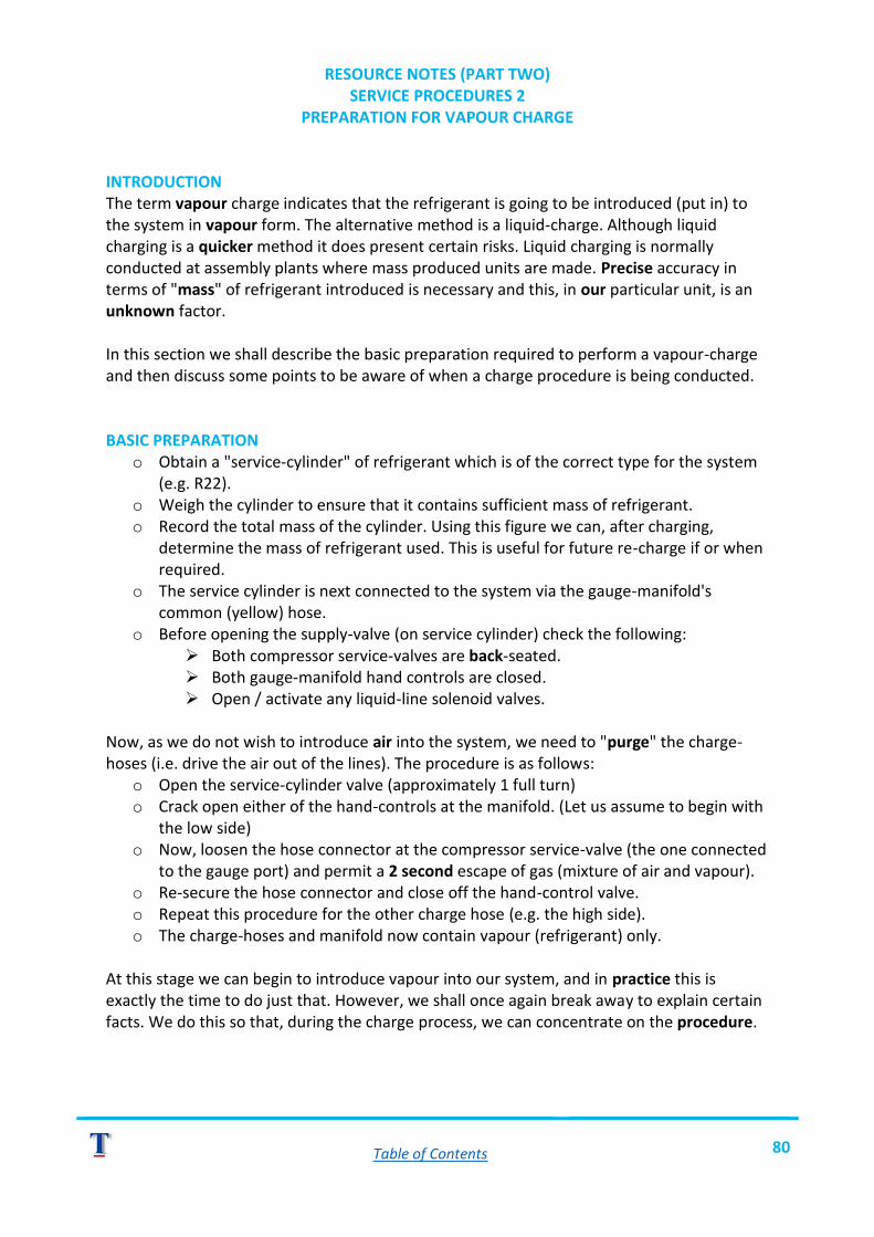
Table of Contents 80
RESOURCE NOTES (PART TWO) SERVICE PROCEDURES 2
PREPARATION FOR VAPOUR CHARGE INTRODUCTION The term vapour charge indicates that the refrigerant is going to be introduced (put in) to the system in vapour form. The alternative method is a liquid-charge. Although liquid charging is a quicker method it does present certain risks. Liquid charging is normally conducted at assembly plants where mass produced units are made. Precise accuracy in terms of "mass" of refrigerant introduced is necessary and this, in our particular unit, is an unknown factor. In this section we shall describe the basic preparation required to perform a vapour-charge and then discuss some points to be aware of when a charge procedure is being conducted. BASIC PREPARATION
o Obtain a "service-cylinder" of refrigerant which is of the correct type for the system (e.g. R22).
o Weigh the cylinder to ensure that it contains sufficient mass of refrigerant. o Record the total mass of the cylinder. Using this figure we can, after charging,
determine the mass of refrigerant used. This is useful for future re-charge if or when required.
o The service cylinder is next connected to the system via the gauge-manifold's common (yellow) hose.
o Before opening the supply-valve (on service cylinder) check the following: ➢ Both compressor service-valves are back-seated. ➢ Both gauge-manifold hand controls are closed. ➢ Open / activate any liquid-line solenoid valves.
Now, as we do not wish to introduce air into the system, we need to "purge" the charge-hoses (i.e. drive the air out of the lines). The procedure is as follows:
o Open the service-cylinder valve (approximately 1 full turn) o Crack open either of the hand-controls at the manifold. (Let us assume to begin with
the low side) o Now, loosen the hose connector at the compressor service-valve (the one connected
to the gauge port) and permit a 2 second escape of gas (mixture of air and vapour). o Re-secure the hose connector and close off the hand-control valve. o Repeat this procedure for the other charge hose (e.g. the high side). o The charge-hoses and manifold now contain vapour (refrigerant) only.
At this stage we can begin to introduce vapour into our system, and in practice this is exactly the time to do just that. However, we shall once again break away to explain certain facts. We do this so that, during the charge process, we can concentrate on the procedure.

Table of Contents 81
ASSESSING A FULL (OPTIMUM) CHARGE CONDITION Because our demonstration refrigeration unit has been assembled from various components (in other words it is not a "designed system") we cannot be sure just how much refrigerant we will require to achieve an "optimum" charge. In fact if we could know the exact specification then we would perform a liquid charge, as mentioned earlier. Charging an "unknown" system, for the first time, is to a large degree, a matter of guess-work and some intelligent interpretation of instrument readings! In principle we generally require:
o Pressure readings - For system pressure. o Temperature readings - For condenser sub-cooling. o Electrical load readings - For compressor load.
PRESSURE Pressure is always the main concern in a system. When pressure on both the suction side and the discharge-side remain "steady" then we have a "stabilised" system. Actual pressure readings will vary considerably from plant to plant depending on factors such as:
o Type of refrigerant in the system. o Type and size of evaporators, condensers, and expansion valves. o Size / capacity of compressor. o Ambient temperatures etc.
Typically a cold-room (not a freezer) plant, operating on R22, in an air-cooled system, might give the following pressures when the system is operating normally:
o Suction side = 425 kPa (62 p.s.i.). o Discharge side = 1700 kPa (230 p.s.i.).
TEMPERATURE Earlier we mentioned "sub-cooling" - we shall now look at this in more detail. One of the most useful assessments of a system's operating condition is made at the condenser. You will however require access to an accurate thermometer which utilises "thermo-couple" probes (recommended type is the "Fluke JF52"). If the return bends of an air-cooled condenser are accessible then we can use them for temperature measuring. Typical readings are shown. The reading at (a) will be approximately equal to the compressor discharge temperature.

Table of Contents 82
The reading at (b) reflects some superheat having been removed by the condenser - (de-superheating).
Then several constant readings (c) are obtained. These indicate that condensing is taking place in this part of the coil.
Finally, at the condenser outlet the condition (d) is measured. This is below the condensing temperature.
This reading has dropped below the condensing temperature by the amount of sub-cooling, which the coil is producing. From this, you can clearly identify the de-superheating, condensing and sub-cooling zones of the condenser.
The amount of sub-cooling is a function of condenser and system design. But if, in the absence of other information, you measure 2°C to 3°C of liquid sub-cooling -that will probably be good. You should get this sub-cooling without any appreciable increase in condensing pressure.
ELECTRICAL LOAD A correctly charged system, operating "on load" will impose a specific electrical load upon the compressor motor. Assuming that the system has been engineered to correct specifications, the compressor motor should operate close to its "rated" amperage draw (i.e. max. operating amps).
An ammeter (tong-tester) is most useful for checking the motor load during the charging procedure. Initially, during a charge, the amperage will be quite low as the compressor will not be working very hard. As the system fills with refrigerant more and more load will be imposed until the "draw" reaches the "rated" figure. At this time we may "assess" that the system has achieved its full charge.
If we combine all the "instrument observations" namely: o Discharge pressure steady.o Sub-cooling @ plus / minus 2°C.o Amperage draw at "rated" value.
Then we may assume that our system is charged.
NOW VIEW THE VIDEO MECHANICAL ACR-4 UP TO REVIEW NO. 2.

Table of Contents 83
SELF-TEST EXERCISE NO. 2 INSTRUCTIONS
o Without reference to your notes or the video answer the questions below. o When you have finished, check your answers by referring to any of the resources.
QUESTIONS YES NO
1. Why is it necessary to “purge” the charge-hoses? ANS: _______________________________________________
2. What 3 important instrument readings do we need to assess an optimum charge? a) _______________________________________________ b) _______________________________________________ c) _______________________________________________
3. What are the 3 “zones” evident in a condenser that is operating efficiently? a) _______________________________________________ b) _______________________________________________ c) _______________________________________________
4. Without “specifications”, what degree of sub-cooling would you expect to see on an “optimally-charged” system? ANS: _______________________________________________
5. A compressor operating at its maximum load will draw what current? ANS: _______________________________________________

Table of Contents 84
RESOURCE NOTES (PART THREE) SERVICE PROCEDURES 2
CHARGE PROCEDURE INTRODUCTION In the previous section we left off the procedure having connected the refrigerant service-cylinder and "purged" the charge-hoses. In this section we shall commence to charge the unit, bearing in mind all that was discussed regarding how to assess the condition of charge. GENERAL PROCEDURE With the refrigerant service-cylinder connected, manifold valves closed, charge-hoses purged and service valves back-seated (as we left off), let us proceed to charge the system. 1) Mid-seat both of the compressors service-valves. 2) Crack the low-side hand-control on your manifold. The high-side control must remain in
the closed position for the whole period of charging. 3) Vapour will now flow from the service-cylinder into the system until the pressure on the
gauges reaches cylinder pressure. NOTE: This pressure will depend on the ambient temperature.
NOTE: It may be necessary to by-pass the low-pressure cut-out switch (where fitted)
in order to activate the compressor. Have your facilitator advice you on this and, where applicable, explain the safety requirements.
4) Start up the unit. Note the behaviour of the compound gauge. If it begins to rise then
sufficient vapour is being drawn. If the pressure falls, then "throttle" the suction valve by moving it toward its front-seat position in order to force better suction out of the service-cylinder. Observe the compound-gauge during this time. It should now begin to rise.
5) If the service cylinder becomes very cold, indicated by "sweating" or "icing", then stand it in a bowl of warm water.
SAFETY: DO NOT heat the cylinder above 50°C and NEVER heat the cylinder with a naked flame.
6) Keep watch on the following items as charging progresses:
o The discharge-pressure. o The sight-glass. o Your ammeter (if connected).
7) Back-off the suction line service-valve as the suction pressure increases. 8) Close-off the manifold control-valve when:
o A clear sight glass flow is observed. o Discharge pressure is steady. o Ammeter reads at "normal load".

Table of Contents 85
9) Allow the system to operate until "stabilising" occurs, (until the system "cycles"). Keep watch on the gauges during this time.
NOW VIEW THE VIDEO UP TO REVIEW NO. 3.

Table of Contents 86
SELF-TEST EXERCISE NO. 3 INSTRUCTIONS
o Without reference to your notes or the video answer the questions below. o When you have finished, check your answers by referring to any of the resources.
QUESTIONS YES NO
1. What action might you take, during a vapour charge, if the suction pressure drops too low? ANS: _______________________________________________
2. What action should you take if the service cylinder begins to frost? ANS: _______________________________________________
3. If your system operates with a “low-pressure cut-out” how do you make the compressor start when pressure is low? ANS: _______________________________________________
4. When can you assume that a system is near to its optimum charge? (3 checks)
a) ________________________________________________ b) ________________________________________________ c) ________________________________________________
PRACTICAL EXERCISE Under the supervision of your facilitator perform the following tasks on your designated unit.
o Prepare the unit to receive a vapour charge. o Charge your unit with the appropriate refrigerant.
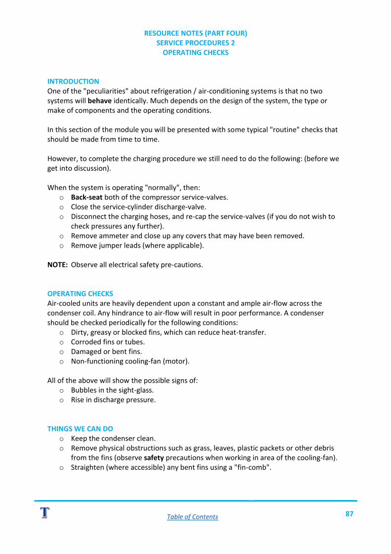
Table of Contents 87
RESOURCE NOTES (PART FOUR) SERVICE PROCEDURES 2
OPERATING CHECKS INTRODUCTION One of the "peculiarities" about refrigeration / air-conditioning systems is that no two systems will behave identically. Much depends on the design of the system, the type or make of components and the operating conditions. In this section of the module you will be presented with some typical "routine" checks that should be made from time to time. However, to complete the charging procedure we still need to do the following: (before we get into discussion). When the system is operating "normally", then:
o Back-seat both of the compressor service-valves. o Close the service-cylinder discharge-valve. o Disconnect the charging hoses, and re-cap the service-valves (if you do not wish to
check pressures any further). o Remove ammeter and close up any covers that may have been removed. o Remove jumper leads (where applicable).
NOTE: Observe all electrical safety pre-cautions. OPERATING CHECKS Air-cooled units are heavily dependent upon a constant and ample air-flow across the condenser coil. Any hindrance to air-flow will result in poor performance. A condenser should be checked periodically for the following conditions:
o Dirty, greasy or blocked fins, which can reduce heat-transfer. o Corroded fins or tubes. o Damaged or bent fins. o Non-functioning cooling-fan (motor).
All of the above will show the possible signs of:
o Bubbles in the sight-glass. o Rise in discharge pressure.
THINGS WE CAN DO
o Keep the condenser clean. o Remove physical obstructions such as grass, leaves, plastic packets or other debris
from the fins (observe safety precautions when working in area of the cooling-fan). o Straighten (where accessible) any bent fins using a "fin-comb".

Table of Contents 88
OTHER CHECKS 1. Compressor - Check that oil is visible in the sight-glass. 2. Expansion Valve - Do not touch or meddle with this. Once it is set or adjusted it needs no
further attention. 3. Filter-Drier - Check for a blocked filter if you see bubbles in the sight-glass. To test a
filter, take a temperature reading at the inlet side connection, and the outlet side connection. Both readings should be identical. A difference in temperatures indicates a blocked filter.
4. Perform a leak-detection check (as described in the last module) periodically, especially on a newly assembled unit.
5. Test operating pressures from time to time, especially on newly assembled units. SHUTTING DOWN A PLANT (Air-cooled with receivers) Should it be necessary for you to stop a unit that is operating, then observe the following tips: (NOTE: Where possible, use the "pump-down" method). Close the liquid line by either switching off the liquid-line solenoid valve or front-seating the receivers' service-valve (king-valve -where fitted). Run the compressor until the low-pressure switch trips the compressor circuit. Isolate the unit at its mains switch. NOTE: Shutting down a system during its normal "run-cycle" is not advised unless an emergency situation has arisen. When this occurs, allow at least 10 minutes for system pressures to stabilise before re-starting.
NOW VIEW THE VIDEO TO THE END.

Table of Contents 89
SELF-TEST EXERCISE NO. 4 INSTRUCTIONS
o Without reference to your notes or the video answer the questions below. o When you have finished, check your answers by referring to any of the resources.
QUESTIONS YES NO
1. What is the most important factor for the satisfactory operation of an air-cooled system? ANS: _______________________________________________
2. What “simple” problem can negatively affect heat transfer out of a condenser? ANS: _______________________________________________
3. List 3 things that we can do in order to maintain condenser efficiency.
a) ________________________________________________ b) ________________________________________________ c) ________________________________________________
4. How do we “test” for a blocked or restricted filter / drier? ANS: _______________________________________________
5. From the test in Question 4, what conclusion can be reached? ANS: _______________________________________________