ai
166
Adobe Illustrator File Format Specification 23 February 1998 Adobe Developer Support PN LPS5007-02 Adobe Systems Incorporated Adobe Systems Europe Limited Adobe House, Mid New Cultins Edinburgh EH11 4DU Scotland, United Kingdom +44-131-453-2211 Adobe Systems Japan Yebisu Garden Place Tower 4-20-3 Ebisu, Shibuya-ku Tokyo 150 Japan +81-3-5423-8100 Corporate Headquarters 345 Park Avenue San Jose, CA 95110-2704 (408) 536-6000 Main Number Eastern Regional Office 24 New England Executive Park Burlington, MA 01803 (617) 273-2120
-
Upload
guestf9a9e7 -
Category
Technology
-
view
743 -
download
11
description
Transcript of ai

Adobe Illustrator File Format Specification
23 February 1998
Adobe Developer Support
PN LPS5007-02
Adobe Systems Incorporated
Adobe Systems Europe LimitedAdobe House, Mid New CultinsEdinburgh EH11 4DUScotland, United Kingdom+44-131-453-2211
Adobe Systems JapanYebisu Garden Place Tower4-20-3 Ebisu, Shibuya-kuTokyo 150 Japan+81-3-5423-8100
Corporate Headquarters345 Park AvenueSan Jose, CA 95110-2704(408) 536-6000 Main Number
Eastern Regional Office24 New EnglandExecutive ParkBurlington, MA 01803(617) 273-2120

Copyright
1998 by Adobe Systems Incorporated. All rights reserved.
NOTICE: All information contained herein is the property of Adobe Systems Incorporated. Many of the intellectual and technical concepts contained herein are proprietary to Adobe, are protected as trade secrets, and are made available only to Adobe licensees for their internal use.
No part of this publication (whether in hardcopy or electronic form) may be reproduced or transmitted, in any form or by any means, electronic, mechanical, photocopying, recording, or otherwise, without the prior written consent of the publisher. Any information referred to herein is furnished under license with Adobe and may only be used, copied, transmitted, stored, or printed in accordance with the terms of such license, or in the accompanying Materials Release Form from Adobe.
PostScript is a registered trademark of Adobe Systems Incorporated. All instances of the name PostScript in the text are references to the PostScript language as defined by Adobe Systems Incorporated unless otherwise stated. The name PostScript also is used as a product trademark for Adobe Systems' implementation of the PostScript language interpreter.
Any references to a “PostScript printer,” a “PostScript file,” or a “PostScript driver” refer to printers, files, and driver programs (respectively) which are written in or support the PostScript language. The sentences in this document that use “PostScript language” as an adjective phrase are so constructed to reinforce that the name refers to the standard language definition as set forth by Adobe Systems Incorporated.
Acrobat, Adobe, Adobe Illustrator, Adobe Garamond, the Adobe logo, Carta, Display PostScript, Distiller, FrameMaker, Lithos, Sonata, and TranScript are registered trademarks and Acrobat Exchange, Acrobat Reader, and the PostScript logo are trademarks of Adobe Systems Incorporated. AppleTalk, LocalTalk, Macintosh, and LaserWriter are registered trademarks of Apple Computer, Inc. IBM is a registered trademark of International Business Machines Corporation. ITC Stone is a registered trademark of International Typeface Corporation. C EXECUTIVE is a registered trademark and CE-VIEW is a trademark of JMI Software Consultants, Inc. Helvetica, Palatino, and Times are trademarks of Linotype-Hell AG and/or its subsidiaries. X Window System is a trademark of the Massachusetts Institute of Technology. Microsoft and MS-DOS are registered trademarks and Windows is a trademark of Microsoft Corporation. Times New Roman is a registered trademark of The Monotype Corporation PLC. NeXT is a trademark of NeXT Computer, Inc. Sun, Sun-3 and SunOS are trademarks of Sun Microsystems, Inc. SPARC is a registered trademark of SPARC International, Inc. Products bearing the SPARC trademark are based on an architecture developed by Sun Microsystems, Inc. SPARCstation is a registered trademark and is a trademark of SPARC International, Inc., licensed exclusively to Sun Microsystems, Inc. UNIX is a trademark registered in the United States and other countries, licensed exclusively through X/Open Company, Limited. Other brand or product names are the trademarks or registered trademarks of their respective holders.
This publication and the information herein is furnished AS IS, is subject to change without notice, and should not be construed as a commitment by Adobe Systems Incorporated. Adobe Systems Incorpo-rated assumes no responsibility or liability for any errors or inaccuracies, makes no warranty of any kind (express, implied or statutory) with respect to this publication, and expressly disclaims any and all warranties of merchantability, fitness for particular purposes and noninfringement of third party rights.

iii
Contents
1 Introduction 7Reporting Errors in this Document 7Adobe Illustrator Format Structure 8Procedure Sets 8Comments 9Extending the Format With Comments and X Operators 10Syntax in Backus-Naur Form 11Encapsulated PostScript Format 13Revisable vs. Final Form 13
2 Prolog 14Header 14Artwork and Ruler Origin 30
3 Script Setup 31Specifying Particular Fonts 32Initializing Resources 32Fonts and Encodings 32Pattern Definition 34Gradients 38
4 Global Objects 51Name Collisions in Global Objects 51
5 Script Body 52Locked Object Operator 54Paint Style 54Paths 54Color 59Overprint Operators 62Containers 63Text as Masks 65
6 Guides 66Guide Operator 66

iv 23 February 1998
7 Object Tags 67
8 Rendering Images (Raster Objects) 68XI Image Operator 68XF Linked Image Operator 69XG Image Link Operator 69Examples 69
9 Layers 71Layer Name — Ln Operator 71Begin Layer — Lb Operator 71Layers Example 72
10 Multi-layer Masks 75Begin Multi-layer Mask — Mb Operator 76Define Multi-layer Mask — Md Operator 76End Multi-layer Mask — MB Operator 76Multi-layer Mask Example 76
11 Color Palette 78Begin Palette — Pb Operator 78End Palette — PB Operator 79Palette Cell None — Pn Operator 79
12 Attributes 81
13 Hyphenation Language — XL Operator 83
14 Nonprinting Elements 84
15 Text 85Revisable and Final-Form Text 85Text Syntax Summary 86Text Operators Summary 87Text Operator Details 93Text Examples 103
16 Placed Art 107Placed Art Operators 107Placed Art Comments 108
17 Graphs 109Syntax 109Graph Objects 111
18 Script Trailer 114
19 Platform-Specific Issues 115Adobe Illustrator on the Macintosh 115Controlling the Grid in Windows and NeXT Versions 118
20 Adobe Illustrator on the Clipboard 120
21 Implementation Issues 121Identifying Adobe Illustrator File Format Versions 121Opening Adobe Illustrator 88 files in Illustrator 6.0 122Adobe Illustrator 6.0 EPS Parser Limitation 122

Contents v
22 List of Operators 123Gradient Operators 126Layer Operators 129Multilayer Masking 130Color Palette 130Attributes 130Text Operators 130
23 Document Syntax Summary 135
Appendix A: Graph Functional Specification 145
A.1 Operators in the Functional Spec 146
A.2 End of the Functional Specification 153
A.3 Graph Customizations 153
Appendix B: Changes Since Earlier Versions 161

vi 23 February 1998

7
Adobe Illustrator File Format Specification
1 Introduction
Adobe Illustrator files can be found in several different formats. These formats, and the glyphs that identify them throughout this document, are as follows:
• Adobe Illustrator 1.0/1.1
• Adobe Illustrator 88
• Adobe Illustrator 3.0/3.2
• Adobe Illustrator 4.0
• Adobe Illustrator 5.0/5.5
• Adobe Illustrator 5.
x
, Japanese Edition
• Adobe Illustrator 6.0
• Adobe Illustrator 7.0
• Adobe Illustrator EPS (Encapsulated PostScript)
Unless noted by the presence of a glyph or otherwise stated in the text, information in this document applies to all versions of Adobe Illustrator files.
Each successive version of Adobe Illustrator introduced new features and capabilities. For the most part, these features are reflected in the content of the Adobe Illustrator document files. Therefore, most remarks that apply to early versions of Adobe Illustrator files also apply to later versions, and later versions exhibit the added complexity of their more advanced feature sets.
1.1 Reporting Errors in this Document
Adobe makes every effort to ensure that this document is accurate and complete. Please address comments and corrections to
1.0/1.1
88
3.0/3.2
4.0
5.0/5.5
Japan
6.0
7.0
EPS

8 Adobe Illustrator File Format Specification 23 February 1998
. Adobe will update the document periodically to incorporate reader comments.
1.2 Adobe Illustrator Format Structure
The documents (files) created by Adobe Illustrator are PostScript language documents. These documents conform to Adobe Systems’
Document Structuring Conventions
, as defined in Appendix G of
PostScript Language Reference Manual, Second Edition
, Addison-Wesley, ISBN 0-201-18127-4. A PostScript language document description that minimally conforms to the Document Structuring Conventions has two main parts: a
prolog
and a
script
.
• The prolog encapsulates information needed by other programs to interpret the file, such as the bounding box that contains all marks on the page. It also contains lists of PostScript language
resources
that the page requires. Such resources include fonts and procedure definitions, which are logically grouped into sets called
procsets
. Procsets contain explicit methods for initializing and terminating their procedures.
• The script describes the graphic elements on the page. It consists of references to the operators and procedures in the prolog, together with operands and data. A script has three logical sections:
– A
setup
sequence that initializes and activates the resources defined in the prolog
– A sequence of
descriptive operators
– A
trailer
that deactivates resources.
The script holds the operators, which are sequences of graphic elements and which are written in the language defined by procsets in the prolog. These sequences consist of collections of data elements, graphic attribute definitions, and calls to the procedures defined in the procsets.
Documents that conform to the Document Structuring Conventions maintain strict separation between the functions of prolog and script: other than definitions, no PostScript code is executed in the prolog, and no new procedures or global variables are defined in the script. However, the script may well set the value of global variables or modify the behavior of procedures defined in the prolog.
1.3 Procedure Sets
Procedures are PostScript language objects, described in
PostScript Language Reference Manual, Second Edition
. Adobe Illustrator groups related procedures into sets and inserts them as required into the printable PostScript files or EPS files it generates. These procedure sets, commonly called procsets, are referenced by comments in the prolog of an Adobe

1 Introduction 9
Illustrator file. When Adobe Illustrator opens a file in Adobe Illustrator format, it parses the file’s prolog to determine what procsets are required for the file. Because the files do not contain the procsets themselves, the files can be considerably smaller than EPS or generic PostScript files that describe the same images.
Readers familiar with the PostScript language will note, on consulting the list of Adobe Illustrator operators (section 22 on page 123), that Adobe Illustrator documents make use of operators that are not explained in
PostScript Language Reference Manual, Second Edition
. These operators are defined by Adobe Illustrator in the procsets it inserts into generated EPS and PostScript language files. Because the PostScript language allows a document to define new operators in its prolog in this way, Adobe Illustrator format cannot properly be considered an extension of the PostScript language. In fact, Adobe Illustrator format is a subset of the PostScript language because it does not make use of all features of the language.
Adobe licenses the Adobe Illustrator procsets for use by developers outside the company. However, the procsets are largely undocumented and unsupported. Developers who wish to receive permission to use and distribute the procsets should contact the Adobe Developers Association at the telephone number (408) 536-9000 or the e-mail address
.
1.4 Comments
The PostScript language treats as a comment any line where the first non-whitespace character is the percent character,
%
. Comments in the PostScript language and the Adobe Illustrator format serve three very different purposes.
• Standard comments are used to document code in the file, as they do in other languages. These comments are meant for human readers, but may also convey meaning to an application or PostScript interpreter when used with certain operators. Standard comments begin with a single percent character:
%Standard Comment
.
• Structural comments are used to express the structure of the file, according to the Document Structuring Conventions (DSC). Structural comments begin with two percent characters:
%%Structural Comment
.
• Pseudo comments are used by applications but are generally ignored by the PostScript interpreter during printing. They allow nonprinting information to be stored in a file using operators that would otherwise result in printed output. Pseudo comments begin with percent and underscore characters:
%_Pseudo Comment
.

10 Adobe Illustrator File Format Specification 23 February 1998
1.4.1 Standard Comments
Standard comments have a special meaning when they begin with the characters
%AI
n_Keyword
, where
n
indicates the Adobe Illustrator version in which
Keyword
was introduced. These comments are typically used with operators to transmit information to an application or to the PostScript interpreter at print time. For example, the
XI
image operator uses structural comments to bound a raster (pixmap or bitmap) image within an Adobe Illustrator file.
%AI5_BeginRaster
[ 0.2049 0 0 0.198 783 164 ] 0 0 526 620 526 620 1 1 0 0 0 0 XI
%FFFFFFFFFFFFFFFFFFFFFFFFFFFFFFFFFFFFFFF780000000000000000000
…Remainder of ASCII pixmap omitted…
%AI5_EndRaster
1.4.2 Structural Comments
In structural comments, the initial
%
character is followed by a second
%
character and a keyword. Many structural comments require information in addition to the keyword. This information is represented as arguments, which are separated from the keyword by a colon and continue on to the newline character that terminates the comment. Thus, all structural comments in a file (following the first one) have the following form:
%%
Keyword
{:
arguments
}
1.4.3 Pseudo Comments
Pseudo comments in Adobe Illustrator format begin with the percent and underline character pair,
%_.
Pseudo comments are generally ignored by the PostScript interpreter but are used by Adobe Illustrator and other applications that read and parse Adobe Illustrator files. For example, the
%_Bs
comments in the following fragment define a gradient that is stored in a file but may not print — it will print only if it is used to paint a printable object. Note also the required comments that mark the beginning and end of the gradient definition.
%AI5_BeginGradient: (Green & Blue)
(Green & Blue) 0 2 Bd
[
1 0.75 0 0 1 50 100 %_Bs
0.6 0 1 0 1 50 0 %_Bs
BD
%AI5_EndGradient
1.5 Extending the Format With Comments and X Operators
Beginning with version 5, Adobe Illustrator introduced multicharacter operators that begin with the
X
character (the
XI
image operator discussed in

1 Introduction 11
1.4.1, “Standard Comments,” is one example). These operators, together with standard and pseudo comments, have been used to extend the Adobe Illustrator file format in a backwards-compatible way because they are understood by newer versions of Illustrator but ignored by earlier versions. Table 1 summarizes the way X operators, standard comments, and pseudo comments are used by newer applications, older applications, and the PostScript interpreter.
Standard comments marked as “conditional” in the table are used by newer applications or PostScript interpreters only when they have relevance — for example, when they are associated with an
X
operator. As described in section1.4.1, “Standard Comments,” the image operator
XI
uses comments to bracket image data. If an older application does not understand the
XI
operator, it ignores it along with the comments and image data. If the
XI
operator is understood, then both the application and the PostScript interpreter read the comments and image data.
Pseudo-comments are generally ignored during printing but are used by applications. This allows nonprinting information to be stored in the file.
With a knowledge of how future versions of Adobe Illustrator will extend the file format, application developers can design parsers with enough flexibility to read newer files while gracefully ignoring newer operators and comments.
1.6 Syntax in Backus-Naur Form
The syntax of Adobe Illustrator document format is summarized using BNF (Backus-Naur form) notation in this document. BNF definitions take the following form:
<xyz>::= <abc> {<def>}* ghi |<k> j
A token enclosed in angle brackets names a class of document component, while plain text appears verbatim in the file, perhaps with some obvious substitution. The grammar rules have two parts:
• On the left of the ::= definition symbol is the name of a class of component. In the example above, the class is
xyz
.
Table 1
Relevance of comments and X operators
File ElementNewer Applications
Older Applications
PostScript Interpreter
X-operator understood ignored understood
Standard Comments conditional ignored conditional
Pseudo Comments understood understood ignored

12 Adobe Illustrator File Format Specification 23 February 1998
• On the right of the definition symbol is a set of one or more alternative forms that an
xyz
component might take in the document. The syntax of the right side of the BNF expressions is as follows:
If there are alternative forms of the component, they are separated by the vertical bar character (|).
The notation
{<abc>}
denotes zero or one instance of
<abc>
.
The notation
{<abc>}*
denotes zero or more instances of
<abc>
.
The notation
<abc>+
means one or more instances of
<abc>
.
The alternative forms are separated by the vertical bar character (|).
Single letter components, such as
<A>
, refer to the corresponding operator
A
.
For example, at the highest level, an Adobe Illustrator document is composed of a prolog and a script. In BNF, this relationship is expressed as follows:
<document> ::= <prolog><script>
The prolog and script can further be defined in BNF as
<prolog> ::= %!PS-Adobe-
M
EPSF-
N
(or
%!PS-Adobe-
M
)
<header comments> %%EndComments %%BeginProlog{<proc set>}*
(not required, but is normally present)
%%EndProlog
<script> ::= <setup>{<layer>}*|{<object>}*{<page trailer>}<document trailer>%%EOF
To describe the entire file structure, the BNF form would next define the components of
<header comments>
,
<proc set>
, and so on, continuing until all the variables in the structure were defined. See “List of Operators” on page 123 for a complete BNF summary of Adobe Illustrator file structure.
The syntax and semantics of the individual operators of the Adobe Illustrator format are defined in later sections of this document. Each operator definition follows this form:
operand
1
…operand
m
op –
The functionality of the
op
operator is explained immediately after the syntax description, (that is, in the position of this paragraph).

1 Introduction 13
The above notation means that the operator
op
takes operands from
1
through
m
and performs some operation. Each operand is characterized either by its data type (for example,
integer
) or a more meaningful name, such as
linewidth
. In the latter case, the range of legitimate values appears in the description. A dash (–) on the left of the operator indicates that an operator requires no operands; a dash on the right indicates that the operator leaves nothing on the stack.
1.7 Encapsulated PostScript Format
Adobe Illustrator can store a document in
encapsulated PostScript file
(EPS) format; however, its default native format is not an official EPS format. EPS format is described in Appendix H of
PostScript Language Reference Manual, Second Edition
. EPS format is closely related to Adobe Illustrator format, but this document does not go into much detail on EPS files, except to point out how they differ from Adobe Illustrator format.
1.8 Revisable vs. Final Form
Documents in Adobe Illustrator format (including Adobe Illustrator EPS) are in
revisable form
. Documents in revisable form contain information (nonprinting gradient definitions, for example) that is needed when the document is opened and edited by an application, but is not required for printing the image described in the document. Printable documents, which do not contain information not needed for printing, are said to be in
final form
.
Note that final-form documents can still be parsed and edited. However, because final-form documents include only information needed for printing, some of the data relationships between objects in the file may be missing when the file is opened by an application.

14 Adobe Illustrator File Format Specification 23 February 1998
2 Prolog
The BNF syntax for an Adobe Illustrator document prolog is:
<prolog> ::= %!PS-Adobe-
M
EPSF-
N
(or
%!PS-Adobe-
M
)
<header> %%BeginProlog{<procset>}*
(not required, but is normally present)
%%EndProlog
<header> ::= <header comments>%%EndComments
<procset> %%IncludeResource:procset <name>
(or)
%%BeginResource:……%%EndResource
%!PS-Adobe-
M
EPSF-
N
(or
%!PS-Adobe-
M
)
The first line of the file is a unique comment that identifies the version of the Document Structuring Conventions (DSC) to which the document conforms. The first line may also specify that the file conforms to a version of the Encapsulated PostScript File format (EPSF). Both numbers must correspond to the specific versions used in writing out the file. For example, the comment
%!PS-Adobe-3.0 EPSF-3.0
indicates that the file conforms to DSC version 3.0 and EPSF version 3.0.
%%BeginProlog
The
%%BeginProlog
comment marks the beginning of the prolog section.
%%EndProlog
The
%%EndProlog
comment marks the end of the prolog section.
2.1 Header
The header for the prolog body of an Adobe Illustrator document follows the version-identifying first line of the file. The syntax for the prolog header is
<header> ::= <header comments>%%EndComments
%%EndComments
The
%%EndComments
comment marks the end of the header part of the prolog.
The sequence of header comments is a subset of those listed in Figure 1 on page 15. The syntax for each comment is described informally. Almost all header comments are optional. Comments required by Adobe Illustrator in all documents are marked
[Required]
. Some comments are required only if a specific feature is used in an illustration. Such comments are marked

2 Prolog 15
[As Necessary]
. When a comment is specific to an Adobe Illustrator version, it is identified by version number. For example:
%AI5_
Keyword
{:
arguments
}
Specific to version
In most cases, a comment specific to an Adobe Illustrator version also has meaning to later versions. The braces in the examples indicate elements that may be omitted from the comment, depending on the requirements of the keyword.
Figure 1
Typical Adobe Illustrator 6.0 header comments
%%Creator: Adobe Illustrator(r) 6.0
%%For: (John Doe) (John Doe Design)
%%Title: (LayeredGradients.ai)
%%CreationDate: (5/9/96) (3:57 PM)
%%BoundingBox: 224 631 268 661
%%HiResBoundingBox: 224.065 631 268 660.5208
%%DocumentProcessColors: Cyan Magenta Yellow
%%DocumentCustomColors: (PANTONE 156 CV)
%%CMYKCustomColor: 0.5 0.5 0.5 0.5 (PANTONE 156 CV)
%%DocumentFonts: CooperBlack
%%+ Minion-Regular
%%DocumentFiles: WrathOfRalph
%%DocumentNeededResources: procset Adobe_level2_AI5 1.0 0
%%+ procset Adobe_typography_AI5 1.0 0
%%+ procset Adobe_screens_AI5 1.0 0
%%+ procset Adobe_blend_AI5 1.0 0
%%+ procset Adobe_Illustrator_AI6_vars Adobe_Illustrator_AI6
%%+ procset Adobe_Illustrator_AI5 1.0 0
%AI5_FileFormat 2.0
%AI3_ColorUsage: Color
%%AI6_ColorSeparationSet: 1 1 (AI6 Default Color Separation Set)
%%+ Options: 1 16 0 1 0 1 1 1 0 1 1 1 1 18 0 0 0 0 0 0 0 0 -1 -1
%%+ PPD: 1 21 0 0 60 45 2 2 1 0 0 1 0 0 0 0 0 0 0 0 0 0 ()
%AI3_TemplateBox: 306 396 306 396
%AI3_TileBox: 31 31 583 761
%AI3_DocumentPreview: None
%AI5_ArtSize: 612 792
%AI5_RulerUnits: 2
%AI5_ArtFlags: 1 0 0 1 0 0 0 1 0
%AI5_TargetResolution: 800
%AI5_NumLayers: 2
%AI5_OpenToView: -78 780 1 826 581 58 0 1 2 40
%AI5_OpenViewLayers: 77
%%EndComments
2.1.1 Header Comments
The individual lines in the header are specified as follows.
%%Creator: Adobe Illustrator(r)
version
The
%%Creator
comment identifies the application that generated the PostScript language document. The version number (version 6.0 in Figure 1) is arbitrary text, terminated by a newline character.
5.0/5.5

16 Adobe Illustrator File Format Specification 23 February 1998
%%For:
(username) (organization)
The
%%For
comment identifies the user who created the file and the organization to which the user belongs. Both username and organization are valid PostScript language strings. The PostScript language string escape sequences for including characters outside the printable ASCII character set and for representing special characters such as “(” and “)” are discussed in PostScript Language Reference Manual, Second Edition.
%%Title: (illustration title) The %%Title comment provides an arbitrary text title for the document. The title is a valid PostScript language string.
%%CreationDate: (date) (time)The %%CreationDate comment gives the date and time that the document was created. The variables date and time are valid PostScript language strings.
%%BoundingBox: llx lly urx ury[Required] The %%BoundingBox comment specifies the imaginary box that encloses all marks painted on the page. Specify the integer coordinates in the default user coordinate system. Negative numbers are allowed.
If a high-resolution bounding box is specified (as described below), the limits of the bounding box are derived from the high-resolution bounding box. To generate the lower left and upper right limits of the bounding box, the high-resolution bounding box llx and lly values are rounded down, and urx and ury values are rounded up.
%%HiResBoundingBox: llx lly urx uryThe %%HiResBoundingBox is contained within the bounding box described above. Therefore, the high-resolution bounding box may be slightly smaller than the bounding box.
The high-resolution bounding box is used for accurate placement of the Adobe Illustrator file as an EPS document. Accurate placement may be required by high-resolution printing devices and by applications, such as FrameMaker®, that can place EPS files within their documents.
%%DocumentProcessColors: keywordThe %%DocumentProcessColors comment specifies which of the process colors identified by the keywords Cyan , Magenta , Yellow , and Black the document uses. This comment is used primarily by programs producing color separations.
%%DocumentCustomColors: (customcolorname) %%+ (customcolorname)
[As Necessary] The %%DocumentCustomColors comment enumerates the names of the custom colors used in the document. The names are valid

2 Prolog 17
PostScript language strings enclosed in parentheses. For example, the PANTONE® colors are identified by names such as PANTONE 156 CV. You may continue the list of custom color names on subsequent lines, each of which must begin with the %%+ prefix.
%%CMYKCustomColor: cyan magenta yellow black (customcolorname)%%+ cyan magenta yellow black (customcolorname)
[As Necessary] The %%CMYKCustomColor comment specifies an approximation for the named custom color in terms of the four components of process color: cyan, magenta, yellow, and black. Each component value must be a real number in the range 0.0 to 1.0. The component values are analogous to the arguments to the PostScript language operator setcmykcolor .
%%DocumentFonts: font…%%+font…[As Necessary] The %%DocumentFonts comment enumerates the names of the PostScript language font programs that the document uses. Fonts listed in the %%DocumentFonts comment are also included in any files which are themselves included (placed) within an Adobe Illustrator document. Omit this comment if the document uses no fonts.
You may need to download a font to the PostScript interpreter before it can properly execute a document description.
%%DocumentNeededFonts: font…[As Necessary] The %%DocumentNeededFonts comment is
included in EPS files. It is followed by a list of fonts that the document requires but are not contained in the file. See PostScript Language Reference Manual, Second Edition, Appendix G, for details about this comment.
%%DocumentSuppliedFonts: font…[As Necessary] The %%DocumentSuppliedFonts comment is
included in EPS files. It is followed by a list of fonts that have been provided in the file. See PostScript Language Reference Manual, Second Edition, Appendix G, for details about this comment.
%%DocumentFiles: filename%%+filename…[As Necessary] The %%DocumentFiles comment names the files that a program must import to render the illustration. Another comment (%%IncludeFile ) marks the site within the illustration at which the file is needed. Omit this comment if no files are to be imported into the document. See section 16, “Placed Art,” for more information on including files.
7.0
7.0

18 Adobe Illustrator File Format Specification 23 February 1998
%%DocumentSuppliedResources: procset name1 version revision%%+ procset name2 version revision
These comments indicate that the named procedure sets and resources are both required and defined by the document. The %%+ procset construction indicates a continuation of the %%DocumentSuppliedResources comment.
Comments appear only for the actual procedure sets needed by the illustration; they are not present when the file is saved in its “no-header” form.
%%DocumentNeededResources: procset name version revision This comment lists the procsets that are required
by the document but are not included within it.
%AI5_FileFormat version This comment is included in EPS files. It specifies which version of Adobe Illustrator created the file. Note that the creator is identified even when a file is saved to be compatible with an earlier version of Adobe Illustrator. The version parameter maps to Adobe Illustrator versions as shown in the following table.
%AI5_ArtSize: height width This comment specifies the size of the artboard in points.
%AI5_RulerUnits: units This comment specifies the ruler or “General” ruler units, as shown in the following table.
Table 2 AI File Format Versions and AI Versions
%AI5_FileFormat Version Adobe Illustrator Version
3 7.0
2.1 6.0.1
2.0 6.0
2.5 5.5
1.2 5.0.1
1.1 5.0
Table 3 %AI5_RulerUnits Parameters
Value of Unit Parameter Meaning
0 inches
1 millimeters
2 points
3 picas
3.0/3.2 6.05.0/5.5
3.0/3.2 6.05.0/5.5
5.0/5.5
5.0/5.5
5.0/5.5

2 Prolog 19
%AI5_ArtFlags: page_setup tiles placed_images patterns split_paths tile_page screens autoscreens gradientsThe nine parameters following this comment are flags that describe
the settings found in the Document Setup dialog. The meanings of their values are shown in the following table.
4 centimeters
Table 4 %AI5_ArtFlags Parameters
Flag Name Flag Value
Meaning
page_setup10
Use page setup.Do not use page setup.
tiles10
Use print tiles.Do not use print tiles.
placed_images10
Show placed images.Do not show placed images.
patterns10
Preview patterns.Do not preview patterns.
split_paths10
Split long paths.Do not split long paths.
tile_page10
Tile full pages.Do not tile full pages.
screens10
Use printer’s default screens.Do not use printer’s default screens.
autoscreens10
Use auto default screens.Do not use auto default screens.This flag is ignored when flag 7 is false.
gradients10
Use compatible gradient printing.Do not use compatible gradient printing.
Table 3 %AI5_RulerUnits Parameters (Continued)
Value of Unit Parameter Meaning
5.0/5.5

20 Adobe Illustrator File Format Specification 23 February 1998
%AI5_TargetResolution: resolutionThis comment specifies the target output resolution.
%AI5_NumLayers: num_layersThis comment specifies the number of layers present in the
document.
%AI5_OpenToView: ulx uly zoom w h view_style ruler tiling ul_monx ul_mony grid snap_gridThe twelve parameters following this comment describe the open
state of the document window. The meanings of the parameter values are described in the following table.
%AI5_OpenViewLayers: layer_numberThe parameter following this comment specifies the number of the
layer to be displayed when the document is opened. If more than one layer is to be displayed, additional parameters follow on separate lines.
Table 5 %AI5_OpenToView Parameters
Parameter Value Meaning
ulx, uly integer The position, in artwork coordinates, of the top left corner of the artwork window.
zoom integer The zoom factor (a negative number represents a zoom factor of1/x).
w, h real Width and height of the artwork window, in pixels.
view_style integer The view style:25 = artwork26 = preview30 = preview selection
ruler boolean Determines whether or not to display the ruler:1 = Show Ruler0 = Hide ruler
tiling boolean Determines whether or not to display tiling:1 = Show tiling0 = Hide tiling
ul_monx ul_mony
integer The upper left position of the artwork window on the monitor.
grid boolean Determines whether or not to display grid:1 = Show grid0 = Hide grid
snap_grid boolean Determines whether or not to snap to grid:1 = Snap to grid0 = Do not snap to grid
5.0/5.5
5.0/5.5
5.0/5.5
5.0/5.5

2 Prolog 21
%%IncludeResource: procset name version revision This comment lists a specific resource to include
in a document. It is present only when the file is saved in its “no-header” format.
%%RGBCustomColor: red green blue (customcolorname)[As Necessary] The %%RGBCustomColor comment lists the
RGB custom color names used in the artwork in terms of the three components of RGB color: red, green, and blue. Each component value must be a real number in the range 0.0 to 1.0. The component values are analogous to the arguments to the PostScript language operator setrgbcolor .
%AI3_TemplateBox: llx lly urx uryThe %AI3_TemplateBox comment specifies the
bounding box that encloses all samples in the document’s template. For more information on templates, see Adobe Illustrator User Guide. Specify the coordinates as integers or reals in the default user coordinate system. Each sample in the template is assumed to be 1⁄72 inch square. The width (urx–llx) and height (ury–lly) of the template box must be integers. If a document has no template, the width and the height of the template box must be zero.
When Adobe Illustrator opens a document, it centers the coordinate ((llx + urx)⁄2, (lly + ury)⁄2 ) in the drawing area.
This comment is named %%TemplateBox .
%AI3_TemplateFile: pathname[As necessary] The %AI3_TemplateFile
comment specifies the template for the illustration. If no name is given, no template is used. The format for specifying the template is:
<volume name>::<directory id (a number)>:<filename>
%AI3_TileBox: llx lly urx ury The %AI3_TileBox comment is used only on the Macintosh version of Adobe Illustrator. It specifies the bounding box of the imageable area of the current page size. See Adobe Illustrator User Guide for more information about tiles and the drawing area. The initial ruler position is centered in this box.
This comment is named %%TileBox .
%AI3_DocumentPreview: keywordThe %AI3_DocumentPreview comment
describes the type of preview image contained in the file. If no preview is included, keyword is None .
3.0/3.2 6.05.0/5.5
7.0
3.0/3.2 6.05.0/5.5
4.0 88
3.0/3.2 6.05.0/5.5
3.0/3.2 6.05.0/5.5
4.0 88
3.0/3.2 6.05.0/5.5

22 Adobe Illustrator File Format Specification 23 February 1998
%AI3_ColorUsage: keyword The %AI3_ColorUsage comment indicates whether the document uses only black or colored ink, indicated by the keyword Black&White or Color , respectively.
This comment is named %%ColorUsage .
%%AI3_PaperRect: ulx uly lrx lryThis comment describes the paper rectangle, relative to the
imageable area, by specifying two points at opposite corners of the rectangle.
Coordinate system values increase left to right, top to bottom. The origin is the upper left corner of the imageable area. The paper rectangle is described in the following order: ulx uly lrx lry where point ul is the upper left corner of the paper and point lr is the lower right corner of the paper.
%AI7_ImageSettings: flag This comment specifies whether or not linked images are embedded in the file. The value of flag is:1 if images are embedded; 0 if images are not embedded.
%AI7_GridSettings: horiz_space horiz_subdiv vert_space vert_subdiv back style gridcolorR gridcolorG gridcolorB subdivcolorR subdivcolorG subdivcolorB
This comment describes gridlines. The parameters are described in the following table.
Table 6 %AI7_GridSettings Parameters
Parameter Type Meaning
horiz_space integer The number of horizontal points between gridlines.
horiz_subdiv integer The number of horizontal subdivisions. This corresponds to the “Gridline every:” setting in the “Guides & Grid” preferences dialog.
vert_space integer The number of vertical points between gridlines. In version 7.0, must be equal to horiz_space.
vert_subdiv integer The number of vertical subdivisions. In version 7.0, must be equal to horiz_subdiv.
back boolean Specifies gridlines in front or in back of the artwork.1 = gridlines in back; 0 = gridlines in front.
style integer Specifies grid style. In version 7.0, only two styles are used:0 = Lines1 = Dots.
3.0/3.2 6.05.0/5.5
4.0 88
3.0/3.2
7.0
7.0

2 Prolog 23
%%AI6_ColorSeparationSet Comment
The %%AI6_ColorSeparationSet comment provides a means to enable users easily to specify a set of color separation parameters by name.
%%AI6_ColorSeparationSet: version magicNumber setnameThe version argument identifies the separation set comment. In
Adobe Illustrator 6.0, values of version not equal to 1 are ignored. With this scheme, future versions of Illustrator may create a new comment format without affecting previous versions.
The magicNumber argument is ignored.
The setname argument is reserved for future use. It associates the comment and subcomment information with a name so that the user can quickly switch between separation sets.
SubComments to %%AI6_ColorSeparationSet
Subcomments of %%AI6_ColorSeparationSet are identified as lines that follow %%AI6_ColorSeparationSet: . Subcomments begin with the characters %%+ and have the following form:
%%+ subcommentname: version magicNumber argument1 … argumentN
The version and magicNumber arguments are identical to the version and magicNumber arguments to the %%AI6_ColorSeparationSet comment. However, the magicNumber argument is used in subcomments.
The version and magicNumber fields allow future expansion of subcomments. Adding newer versions of subcomments after older versions facilitates backwards compatibility. For example, if a version = 2 subcomment is introduced, the developer can add this new subcomment version after the older version = 1 subcomment. Newer versions of Illustrator will recognize the new comment and override the older information; older versions of Illustrator will ignore the newer comment and use the older information.
gridcolorRgridcolorGgridcolorB
real RGB components of the gridlines.
subdivcolorRsubdivcolorGsubdivcolorB
real RGB components of the subdivisions.
Table 6 %AI7_GridSettings Parameters (Continued)
Parameter Type Meaning
6.0

24 Adobe Illustrator File Format Specification 23 February 1998
%%++ Options Subcomment to %AI6_ColorSeparationSet
%%++ Options: version magicNumber separate level2 ASCIIOutput portrait emulsiondown negative overprintblack convertoprocess previewart usedefaultmarks layers bleed artbounds.left artbounds.top artbounds.right artbounds.bottom cropbounds.left cropbounds.top cropbounds.right cropbounds.bottom halftoneindex pagesizeindex
The arguments to %%++ Options have the following meanings:
version = 1 (indicates version1).
magicNumber = 16 in version 1.
level2 = 1 to separate the output.= 0 for composite output.
separate = 1 for Level 2 output.= 0 for Level 1 output (user input from Print dialog).
ASCIIOutput = 1 for ASCII output of images.= 0 for binary output of images (user input from print dialog).
portrait = 1 for portrait orientation.= 0 for landscape orientation.
emulsiondown = 1 for emulsion down.= 0 for emulsion up.
negative = 1 for a negative image.= 0 for a positive image.
overprintblack = True to overprint black; False otherwise.
convertoprocess = True to convert to process color; False otherwise.
previewart = True to preview artwork; False otherwise.
usedefaultmarks = True to use default crop marks; False otherwise.
layers = 1 if separating printable layers.= 2 if separating visible layers.= 3 if separating all layers.
bleed A real number, expressed in points, that specifies the distance to outset the crop marks from the crop bounds. It also specifies the distance that artwork can extend beyond the crop bounds.

2 Prolog 25
This bleed area extends from cropbounds to cropbounds.left – bleed, cropbounds.right + bleed, cropbounds.top + bleed, and cropbounds.bottom – bleed. Note that cropbounds and artbounds are referenced to default user space, where the origin is at the lower left and the x and y axes extend positive right and positive up, respectively (see section 2.2, “Artwork and Ruler Origin,” on page 30).
artbounds.leftartbounds.top
artbounds.rightartbounds.bottom Real numbers, expressed in points. These values indicate the user-defined
location of the artwork relative to the separation page size in the default user space coordinate system. Users often move their artwork on the separation page to save film.
The location of the artbounds boundary is independent of the artwork in the Illustrator document. The size of the boundary is tied to the size of the artwork in the Illustrator document. If a user sets the artbounds boundary in the separation dialog, then increases the size of the artwork in the Illustrator document and attempts to separate without resetting the boundary in the separation dialog, he will be presented with an alert warning him of clipped separation output. No warning is presented if the artwork is moved or decreased in size in the Illustrator document.
cropbounds.leftcropbounds.top
cropbounds.rightcropbounds.bottom Real numbers, expressed in points relative to the separation page size. The
cropbounds boundary crops the artbounds boundary on the separation page and, in conjunction with the bleed argument, identifies where the separation marks are to be placed.
halftoneIndex A zero-based index into the halftone list that specifies the separation halftone. The %%+ Halftone subcomment builds the halftone list.
pageindex A zero-based index into the page list that specifies the separation page size. The %%+ PageSize subcomment builds the pagesize list.
%%+ PPD Subcomment to %AI6_ColorSeparationSet
%%+ PPD: version magicNumber customAvailable rollFedDevice defaultHalftone.frequency defaultHalftone.angle defaultHalftone.screenIndex defaultHalftone.transferIndex deviceAdjust.a deviceAdjust.b deviceAdjust.c deviceAdjust.d deviceAdjust.h deviceAdjust.v customMaximum.h customMaximum.v customImageArea.left customImageArea.top customImageArea.right customImageArea.bottom ppdFile.vRefNum ppdFile.dirID ppdFile.fileName

26 Adobe Illustrator File Format Specification 23 February 1998
version = 1 (indicates version1).
magicNumber = 21 in version 1.
customAvailable A boolean value taken from the ParamCustomPageSize or VariablePaperSize keys in the PPD file for the output device.
RollFedDevice = True if the HWMargins key does not exist in the PPD file.
defaultHalftone.frequencydefaultHalftone.angle
defaultHalftone.screenIndexdefaultHalftone.transferIndexFrom the ScreenFreq, ScreenAngle, ScreenProc, Transfer,
DefaultScreenProc and DefaultTransfer PPD keys. The screenIndex is a zero-based index into the screen procedure string list (see the StringAdd subcomment below). The transferIndex is a zero-based index into the transfer procedure string list (see StringAdd).
deviceAdjustMatrix.adeviceAdjustMatrix.bdeviceAdjustMatrix.cdeviceAdjustMatrix.ddeviceAdjustMatrix.edeviceAdjustMatrix.hdeviceAdjustMatrix.v Reserved for future use.
customMaximum.hcustomMaximum.v Taken from the ParamCustomPageSize or MaxMediaWidth or
MaxMediaHeight keys in the PPD file.
customImageArea.leftcustomImageArea.top
customImageArea.rightcustomImageArea.bottomTaken from the HWMargins PPD key, or derived from the customMaximum.h
and customMaximum.v arguments.
ppdFile.vRefNum (Macintosh only) The volume reference number (not a WDRefNum) of the PPD file location.
ppdFile.dirID (Macintosh only) The directoryID of the ppd file location.
ppdFile.fileName The file name of the PPD file.
%%+ StringAdd and %%+ StringSplit Subcomments to %AI6_ColorSeparationSet
%%+ StringAdd: version magicNumber listID stringLength string
%%+ StringSplit: version magicNumber listID stringLength string

2 Prolog 27
Many PostScript procedures are extracted from the PPD file for the output device. The %%+ StringSplit subcomment stores these strings in one of three string lists:
• The screen list contains procedures for halftone screens.
• The transfer list contains procedures for transfer functions.
• The pagesize initialization list contains procedures for setting up a page environment.
Strings that would cause a comment line to exceed 255 characters are split into multiple lines with the %%+ StringSplit subcomment.
version = 1 (indicates version1).
magicNumber = 3 in version 1.
listID = 1 for the screen procedure string list.= 2 for the transfer procedure string list.= 3 for the page size initialization procedure string list.
stringLength The length of the string.
string The string data. The string starts one space after the stringLength argument and extends for stringLength bytes.
%%+ Halftone Subcomment to %AI6_ColorSeparationSet
%%+ Halftone: version magicNumber halftoneName translatedName unused cyan.angle cyan.frequency cyan.screen cyan.transfer magenta.angle magenta.frequency magenta.screen magenta.transfer yellow.angle yellow.frequency yellow.screen yellow.transfer black.angle black.frequency black.screen black.transfer custom.angle custom.frequency custom.screen custom.transfer
Most of these arguments are the angle, frequency, screen and transfer values for the four process colors plus the values for the custom color (spot color) plates.
version = 1 (indicates version1).
magicNumber = 23 in version 1.
halftoneName The halftone name is extracted from the ColorSepScreenFreq, ColorSepScreenAngle, ColorSepScreenProc and ColorSepTransfer PPD keys.
translatedName The translated name is extracted from the ColorSepScreenFreq, ColorSepScreenAngle, ColorSepScreenProc and ColorSepTransfer PPD keys.
28 Adobe Illustrator File Format Specification 23 February 1998
cyan.anglemagenta.angle
yellow.angleblack.angle
custom.angle The screen angles are extracted from the ColorSepScreenAngle PPD key.
cyan.frequencymagenta.frequency
yellow.frequencyblack.frequency
custom.frequency The screen frequencies are extracted from the ColorSepScreenFreq PPD key.
cyan.screenmagenta.screen
yellow.screenblack.screen
custom.screen A zero-based index into the screen procedure string list. The screen procedure is extracted from the ColorSepScreenProc PPD key.
cyan.transfermagenta.transfer
yellow.transferblack.transfer
custom.transfer A zero-based index into the transfer procedure string list. The transfer procedure is extracted from the ColorSepTransfer PPD key.
%%+ Process Subcomment to %AI6_ColorSeparationSet
%%+ Process: version magicNumber status frequency angle plate
version = 1 (indicates version1).
magicNumber = 4 in version 1.
status = 0 for “do not separate.”= 1 for “separate.” = 2 for “convert to process.” “Convert to process” only applies to custom plates and should never be set for process color plates.
frequency The screen frequency for the plate.
angle The screen angle for the plate.
plate = 0 for the cyan plate.= 1 for the magenta plate.= 2 for the yellow plate.= 3 for the magenta plate.
2 Prolog 29
%%+ Custom Subcomment to %AI6_ColorSeparationSet
%%+ Custom: version magicNumber status frequency angle colorName
version = 1 (indicates version1).
magicNumber = 4 in version 1.
status = 0 for “do not separate.”= 1 for “separate.” = 2 for “convert to process.”
frequency The screen frequency for the plate.
angle The screen angle for the plate.
colorName The name of the custom color.
%%+ PageSize Subcomment to %AI6_ColorSeparationSet
%%+ PageSize: version magicNumber pageProc custom transverse offset width height imageArea.left imageArea.top imageArea.right imageArea.bottom mediaName translation
version = 1 (indicates version1).
magicNumber = 12 in version 1.
pageProc A zero-based index into the page size initialization string procedure list.
custom True if this is a custom page entry; False otherwise.
transverse True if the page is transverse; False otherwise. This value may be changed by the user in a custom page.
offset A real number, expressed in points, that describes the offset between separation pages.
width A real number, expressed in points, that describes the width of the page. This value corresponds to the custom maximum for custom pages.
height A real number, expressed in points, that describes the height of the page. This value corresponds to the custom maximum for custom pages.
imageArea.leftimageArea.top
imageArea.rightimageArea.bottom Real numbers, expressed in points, that describe the imageable boundaries of
the page in default user space, where the origin is at the lower left and the x and y axes extend positive right and positive up, respectively.

30 Adobe Illustrator File Format Specification 23 February 1998
mediaName The PostScript procedure name used to invoke page setup information.
translation The translated name of mediaName, presented to the user in page setup, print setup, and print dialogs.
2.2 Artwork and Ruler Origin
All artwork elements, as well as the Bounding Box, Template Box, and Tile Box, are written out in coordinates relative to the ruler origin, with y increasing up and x increasing to the right, and bounds in the order left, bottom, right, top.
The template, if there is one, is always centered on the artboard. If there is no template associated with the artwork, the %AI3_TemplateBox comment describes a degenerate box positioned at the center of the artboard. Since it is written out in ruler-relative coordinates, the center of the template bounding box can be used to establish the ruler origin by measuring backwards from the center of the current artboard (that is by measuring x to the left of the center of the template bounding box and y down from the center). It is done this way because the size of the artboard may change between the Adobe Illustrator version under which a file is saved and the version with which it is subsequently opened. In such a situation, it is the centers of the two artboards that must be aligned.
That is, when the file is opened, the Template Box rectangle is read in, and then the ruler origin is calculated as:
x = (artboard width – templateBox.left – templateBox.right) / 2y = (artboard height + templateBox.top + templateBox.bottom) / 2
(This x,y is in Macintosh coordinate space, where y increases down, unlike the Adobe Illustrator file format, where y increases up.)
The position of the ruler, of course, is only really meaningful inside Adobe Illustrator or another application that wishes to import Adobe Illustrator files while keeping the ruler position intact. For applications that do not care about the ruler position of Adobe Illustrator, it is sufficient to choose as an origin any point pertinent to the importing application, such as one of the corners of the bounding box, and apply to all the points in the artwork the translation that would take that point to 0,0.

3 Script Setup 31
3 Script Setup
The syntax for the script setup section of an Adobe Illustrator document is
<script> ::= <setup>{<layer>}*|{<object>}*{<page trailer>}<document trailer>%%EOF
<setup> ::= %%BeginSetup{%%IncludeFont: font}*{<procset init>}*<font encoding><gradient defs><color palette><pattern defs><gradient defs>%%EndSetup
<procset init> ::= <dict name>+ /initialize get exec
<gradient defs> ::= <Bn><gradient def>+
<gradient def> ::= %AI5_BeginGradient: (gradient name) <Bd>{<ramp data>} <color stops> <BD> %AI5_EndGradient
<color palette> ::= %AI5_BeginPalette<Pb><Pn>*<Pc>*<PB>%AI5_EndPalette
<ramp data> ::= [ <%_Br>+
<color stops> ::= [ <%_Bs>+
<page trailer> ::= %%PageTrailergsave annotatepage grestore showpage
<document trailer> ::= %%Trailer{<proc set termination>}*
The following sections describe the individual components of the setup section of an Adobe Illustrator document.

32 Adobe Illustrator File Format Specification 23 February 1998
3.1 Specifying Particular Fonts
The comment %%IncludeFont specifies a font that appears in the document. Adobe Illustrator checks to see whether that font is available and uses it if it is. If the font is not available, Adobe Illustrator uses another font.
3.2 Initializing Resources
Adobe Illustrator customarily initializes those resources (proc sets) required by the document. A corresponding termination appears in the document trailer.
3.3 Fonts and Encodings
The mapping between ASCII characters and glyphs in a font is different from the standard mapping used in a PostScript font. Therefore, to print a document correctly, the mapping must be changed for each PostScript font used in an Adobe Illustrator document. The action of altering the mapping between character codes and glyphs is called re-encoding the font.
The syntax for re-encoding a font in an Adobe Illustrator document is
<font encoding> ::= [{<encoding pairs>}*<TE>{<re-encoding>}*
<encoding pairs> ::= (list of encoding number–glyph name pairs)
<re-encoding> ::= %AI3_BeginEncoding: newFontName oldFontName<TZ>%AI3_EndEncoding <font type>
<font type> ::= AdobeType|TrueType
3.3.1 Font Encoding Operators
The TE operator sets the standard encoding for the platform on which the Adobe Illustrator file is being executed. The TZ operator performs the re-encoding. After encoding has been specified, the Tf operator can specify the font name and the font size.
[encodingPairs TE The TE operator sets the standard platform font encoding. Note that there is no right bracket following the encodingPairs parameter.

3 Script Setup 33
The encodingPairs operand is a list of encoding numbers and literal glyph names organized as follows:
code 1/name 11/name 12/…/name 1jcode 2/name 21/name 22/…/name 2k…
code n/name n1/name n2/…/name nl
where each code is in the range 0 to 255 and each name is the literal glyph name. The / preceding each name is the syntax used to distinguish a PostScript language literal name from an executable name. This list describes a set of sequences of glyph names to install in the new encoding vector. Each sequence begins with the character index of the first name to be replaced. Subsequent names are replaced up to the next character index entry in encodingPairs, at which point a new sequence of replacement names begins, starting with the one at the new character index.
The TZ operator creates a new font from an existing font by changing portions of the new font’s encoding vector. The operator can take several forms, as shown in the syntax description below.
[ newFontname oldFontName direction fontScript useDefault TZ[ encodingPairs newFontName oldFontName direction fontScript useDefault TZ[ newFontName oldFontName direction fontScript useDefault [w0 w1…wn] TZ[ encodingPairs newFontName oldFontName direction fontScript useDefault [w0 w1…wn] TZ
The first two forms of the TZ operator are for Type 1 font programs; the second two forms are for Multiple Master typefaces. The forms with the encodingPairs operand are used when changing font encoding. These encodings are platform-specific; on some platforms there may be no encodingPairs operand.
The encodingPairs operand is a list of encoding numbers and literal glyph names as described for the TE operator.
The newFontName and oldFontName operands are the PostScript names for the new font and the original font. These names must be the same as the names given in the %%BeginEncoding comment.
For composite fonts (such as Japanese language fonts), the [encodingPairs list must have a single left bracket. The direction and fontScript operands for composite fonts can take the following values:
Operand Value Meaning
direction 0 Horizontal writing
1 Vertical writing

34 Adobe Illustrator File Format Specification 23 February 1998
Note For versions of Adobe Illustrator other than Adobe Illustrator 3.x and Adobe Illustrator Japanese Edition, there is no direction operand. The Windows version of Adobe Illustrator Japanese Edition ignores the direction operand.
The defaultEncoding operand controls whether the TE encoding is used (1) or not (0). The defaultEncoding operand should be 0 if the font is not a standard encoding Type 1 font (for example, a pi font, non-Roman font, or TrueType font). If the font is a Multiple Master typeface, the final array operand is the weightVector of the Multiple Master instance.
Figure 2 shows how to use the TZ operator. The example derives a new font named _Times-Roman from the original Times-Roman font. It replaces three sequences of characters within the encoding vector; the first one-character sequence is number 39, the second one-character sequence is number 96, and the third sequence replaces the characters numbered 128 and above.
Figure 2 Re-encoding Times Roman with the TZ operator
%%BeginEncoding: _Times-Roman Times-Roman
[ 39/foo 96/bar 128/bzaa/bazb
/_Times-Roman/Times-Roman 0 0 1 TZ
%%EndEncoding
3.4 Pattern Definition
The script setup section of a document defines the patterns used by Adobe Illustrator. A pattern is essentially just another Adobe Illustrator illustration that can be drawn repeatedly. You cannot use placed files nor graph objects within a pattern, but patterns can include paths and text. Therefore, parts of the description of how patterns are defined necessarily refers to the description of how an illustration is described in the document script section.
Each pattern is defined by a rectangle used to tile the drawing area. The illustration within that rectangle constitutes the pattern used when a path is stroked or filled with a pattern.
The syntax for a pattern is
<pattern defs> ::= {<pattern>}*
fontScript 0 Roman typefaces
1 Japanese typefaces
2 Traditional Chinese typefaces
3 Korean typefaces
25 Simplified Chinese typefaces
Operand Value Meaning

3 Script Setup 35
<pattern> ::= %AI3_BeginPattern: (patternname)<E>%AI3_EndPattern
(patternname) llx lly urx ury [<pattern layer list>] EThe E operator defines a new pattern called patternname using the layer list for which the bounding box is specified by (llx, lly) and (urx, ury).
Note Do not confuse the term “layers” as used in this section with the document layers feature introduced in Adobe Illustrator 5.0. The layers discussed here simply describe the paint order of objects.
The syntax for the list of layers in a pattern is as follows:
<pattern layer list> : := {<pattern layer>}*
<pattern layer> ::= <@><&>
Each layer of the pattern consists of two parts. The first part defines the color to be used for filling and stroking the pattern. The second part defines the other style parameters and the paths for drawing the pattern.
(colordefinition) @ The @ operator defines the color and overprinting style for the associated layer in the pattern. The colordefinition parameter begins with a specification of the overprinting option. For more information on overprinting, see the definitions of operators O and R in section 5.4, “Color.” The filling or stroking color is then defined using the simple gray operators (g and G), the process color operators (k and K), or the custom color operators (x and X). All color operators are defined in section 5.4, “Color.”
(tiledefinition) & The & operator defines the tile for the pattern layer that includes the drawing styles and illustration components. This is identical to the representation of objects in the document script except that the color components and both parts of the object are specified separately as PostScript language strings, which are enclosed in parentheses. The use of strings limits the size of a pattern layer definition to 64K bytes.
Whenever a pattern background is filled or stroked, the first layer of the pattern defines the background for the tile. If the pattern tile rectangle is filled but not stroked, then you can use the special _ (underbar) operator to specify a fill. If the pattern tile rectangle is stroked, then normal path construction of the rectangle specifies the pattern tile to stroke. (Breaking down the filling and stroking of the pattern tile results in performance optimization when imaging.)
– _ The _ (underbar) operator signals the pattern machinery that the tile rectangle for the path is to be filled with the fill color previously specified to the @ operator. Figure 3 shows an example pattern definition.

36 Adobe Illustrator File Format Specification 23 February 1998
Figure 3 An example pattern definition
%AI3_BeginPattern: (no vegetation)
(no vegetation) 6.4 6.4 113.5 103 [
%AI3_Tile
(0 O 0 R 0.06 0.09 0.23 0 (PANTONE 468 CV) 0 x 0.06 0.09 \
0.23 0 (PANTONE 468 CV) 0 X) @
(
%AI6_BeginPatternLayer
800 Ar
0 J 0 j 3.6 w 4 M []0 d
%AI3_Note:
0 D
0 XR
111.7 8.2 m
111.7 101.2 L
8.2 101.2 L
8.2 8.2 L
111.7 8.2 L
f
%AI6_EndPatternLayer
) &
(0 O 0 R 0.18 0.3 0.56 0 (PANTONE 465 CV) 0 x 0.18 0.3 0.56 \
0 (PANTONE 465
CV) 0 X) @
(
%AI6_BeginPatternLayer
800 Ar
0 J 0 j 3.6 w 4 M []0 d
%AI3_Note:
0 D
0 XR
111.7 8.2 m
111.7 101.2 L
8.2 101.2 L
8.2 8.2 L
111.7 8.2 L
s
%AI6_EndPatternLayer
) &
] E
%AI3_EndPattern
The example in Figure 3 defines a pattern called “no vegetation” where the pattern tile is both filled and stroked.
The first line gives the pattern name; the second line specifies the bounding box for the pattern tile. The fourth line begins a layer list describing the pattern tile. The first item in the layer list specifies the color PANTONE 468 CV as the fill color of the pattern tile; the next layer in the pattern specifies the custom color PANTONE 465 CV as the stroke color of the pattern tile.
Following the color specification is the drawing of the pattern tile itself. Each path in the tile pattern layer is specified with a sequence of m (moveto ) and L
pattern tile

3 Script Setup 37
(lineto ) operations. The first pattern layer is filled (by means of the f operator); the second layer is stroked (by means of the s operator).
See section 5.2 on page 54 for a description of the style options selected at the beginning of the tile definition

38 Adobe Illustrator File Format Specification 23 February 1998
3.5 Gradients
Gradients within Adobe Illustrator files are sometimes referred to as blends. Gradients are global objects, which are defined in the setup section of the file. Objects that are painted with gradients (instances of the gradient) are found later in the file and refer to the definition in the setup section.
The description of an Illustrator gradient is basically a description of the settings in the Adobe Illustrator 6 Gradient palette (Figure 4). The user interface for the Gradient palette is different in later versions of Illustrator (the Illustrator 7 Gradient palette is shown in Figure 5), but the gradient information stored in a document’s data file is the same.
Figure 4 Illustrator 6 Gradient Palette
Functions of the Illustrator 6 Gradient palette have been distributed among three palettes in Illustrator 7: Gradient, Color, and Swatches (all are shown in Figure 5). The Gradient palette is used to create gradients and, in combination with the Color palette and Swatches palette, to modify existing gradients. The gradient name shown in earlier versions has been abandoned in Illustrator 7 in favor of choosing a gradient visually from the Swatches palette. Color specifications for ramp points in the Gradient Ramp are assigned in the Color palette.
Gradient colors can be assigned as CMYK process color, a spot color, or, (in Illustrator 7) RGB process color. When a gradient is printed or separated,
5.0/5.5
type
name
colorSpec
colorStyle
0% 100%Gradient Ramp
rampPoint
midPointnColors
7.0
7.0

39
RGB colors and RGB-CMYK mixed-mode gradient colors are all converted to CMYK process color.
Figure 5 Illustrator 7 Gradient, Color, and Swatches palettes
The BNF syntax of a gradient is as follows:
<gradient defs> ::= <Bn><gradient def>+
<gradient def> ::= %AI5_BeginGradient: (gradient name) <Bd>{<ramp data>} <color stops> <BD> %AI5_EndGradient
<ramp data> ::= [ <%_Br>+
<color stops> ::= [ <%_Bs>+
7.0
type
colorSpeccolorStyle
Gradient Ramp
rampPoint
midPoint
nColors
40 Adobe Illustrator File Format Specification 23 February 1998
3.5.1 Number of Gradients — Bn Operator
The Bn operator appears in the setup section of the document.
nblends Bn The Bn operator indicates the number of cached gradients, or blends, in the document. The number of gradients is specified by the integer argument nblends.
For example, if a document contained a two gradients, the following description would apply:
%%BeginSetup
2 Bn
The Bn operator is required only if the document contains gradients. Otherwise, it need not be present.
3.5.2 Gradient Definitions
Following the Bn operator are definitions of all gradients in a document. Each of these begin with a comment and the name of the gradient:
%AI5_BeginGradient: ( gradient name )
Begin Gradient Definition — Bd Operator
A gradient has three basic descriptors: the name, the type, and the number of colors. These are specified with the gradient description begin operator (Bd), as follows:
name type nColors Bd The Bd operator is required for each gradient definition. The three arguments can assume the following values:name String containing the name of the gradient. This
name is used in subsequent references to thegradient.
type 0 = Specifies linear gradient.1 = Specifies radial gradient.
nColors Integer specifying the number of colors in thegradient.
For example, a linear gradient with two colors might begin as follows:
%AI5_BeginGradient: (Red & Yellow)
(Red & Yellow) 0 2 Bd

41
Color Stops — %_Bs Operator
Color stop descriptions, equal in number to the number of colors specified in the gradient, follow the Bd operator. Each gradient has at least two color stops.
A color stop description has a variable number of arguments, depending on the type of colors that it contains. The color stop begin operator is %_Bs , with the following syntax:
colorSpec colorStyle midPoint rampPoint %_BsThe arguments can assume the following values:
rampPoint — a number giving the position of a color stop on the gradient ramp. The gradient ramp is a distance from 0 to 100% of the length along the gradient vector needed to fully create the gradient. The first ramp point does not have to be at 0; the last does not have to be at 100. When the gradient has several ramp points, their values must satisfy the following equation:
rampPoint1 < rampPoint2 < rampPoint3 …
midPoint — specifies the location between two ramp points where there is an equal mix of the two colors. midPoint is a percentage of the distance between two ramp points, expressed as a number between 13 and 87. The mid point for the last color stop is ignored.
colorStyle — indicates the type of color making the color stop. colorStyle can take on one of three values, as described in the following table.
Table 7 Values for colorStyle Argument
Value colorStyle
0 Gray
1 CMYK
2 RGB
3 CMYK custom color
4 RGB custom color

42 Adobe Illustrator File Format Specification 23 February 1998
colorSpec — indicates the percentage to be used of each color at the color stop ramp point (except for the custom color name, where the value is a string). The number of arguments represented by colorSpec depends on the colorStyle of the color stop, as described in the following table.
The following example is a typical use of the %_Bs operator:
[
0 1 0.6 0 1 50 100 %_Bs
% CMYK ends at 100 percent
0.05 0.2 0.95 0 (Gold) 0 3 50 0 %_Bs
% Custom color starts at 0 percent, midpoint at 50 percent
The following example shows a typical gradient definition:
%%BeginSetup
...
1 Bn
%AI5_BeginGradient: (White & Purple Radial)
(White & Purple Radial) 1 2 Bd
[
0.55 1 0 0 1 50 10 %_Bs
0 0 0 0 1 50 100 %_Bs
BD
%AI5_EndGradient
...
%%EndSetup
Note that the %%BeginSetup and %%EndSetup comments appear only once in a document file.
Gradient Ramps — %_Br Operator
An additional piece of information is sometimes included in a gradient description: a description of the gradient ramp, specified by means of the %_Br operator. If the file is being written for imaging purposes (for example, sending a PostScript file to a printer or writing an EPS file), this information
Table 8 Number of Arguments and Values for colorSpec
colorStyleNumber of colorSpec Arguments
colorSpec Arguments
Gray (0) 1 gray
CMYK (1) 4 cyan magenta yellow black
RGB (2) 7 cyan magenta yellow black red green blue
CMYK custom color (3) 6 cyan magenta yellow black name tint
RGB custom color (4) 10 cyan magenta yellow black red green blue name tint type (value of type is always 1 for RGB)
43
is required. If the file is being written for use within Adobe Illustrator or as common file format, this information can be ignored.
The %_BR operator is defined as follows:
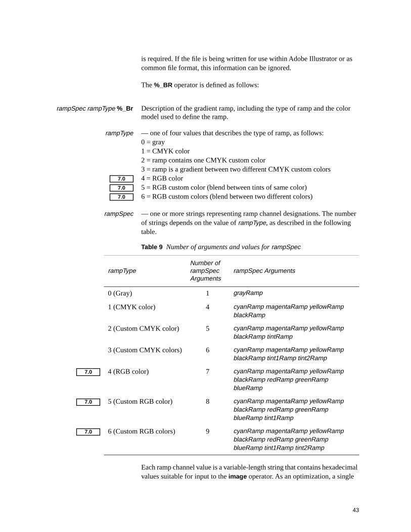
rampSpec rampType %_Br Description of the gradient ramp, including the type of ramp and the color model used to define the ramp.
rampType — one of four values that describes the type of ramp, as follows:0 = gray1 = CMYK color2 = ramp contains one CMYK custom color3 = ramp is a gradient between two different CMYK custom colors4 = RGB color5 = RGB custom color (blend between tints of same color)6 = RGB custom colors (blend between two different colors)
rampSpec — one or more strings representing ramp channel designations. The number of strings depends on the value of rampType, as described in the following table.
Each ramp channel value is a variable-length string that contains hexadecimal values suitable for input to the image operator. As an optimization, a single
Table 9 Number of arguments and values for rampSpec
rampTypeNumber of rampSpec Arguments
rampSpec Arguments
0 (Gray) 1 grayRamp
1 (CMYK color) 4 cyanRamp magentaRamp yellowRamp blackRamp
2 (Custom CMYK color) 5 cyanRamp magentaRamp yellowRamp blackRamp tintRamp
3 (Custom CMYK colors) 6 cyanRamp magentaRamp yellowRamp blackRamp tint1Ramp tint2Ramp
4 (RGB color) 7 cyanRamp magentaRamp yellowRamp blackRamp redRamp greenRamp blueRamp
5 (Custom RGB color) 8 cyanRamp magentaRamp yellowRamp blackRamp redRamp greenRamp blueRamp tint1Ramp
6 (Custom RGB colors) 9 cyanRamp magentaRamp yellowRamp blackRamp redRamp greenRamp blueRamp tint1Ramp tint2Ramp
7.0
7.0
7.0
7.0
7.0
7.0

44 Adobe Illustrator File Format Specification 23 February 1998
integer value is written out for strings that would contain the same data throughout the ramp. For example, the hexadecimal value 01010101 is written as the integer 1; the value FFFFFFFF is written as the integer 255.
End Gradient Description — BD Operator
The gradient description ends with the required gradient description end operator BD:
BD Terminate gradient definition.
3.5.3 Gradient Instances
When a gradient is used in to fill an object, a gradient instance is specified. The BNF syntax for a gradient instances is as follows:
<gradient instance> ::=<Bb><Bh> |<Bg> |{<Xm>} |<Bm> |<Bc> |<f> <BB>
The gradient instance includes information such as the origin point and transformation matrix for the gradient. The following example shows a filled path and the section of an Illustrator file that generates it:
Figure 6 A closed rectangular path filled with a gradient.
% The object description (a rectangle).
0 D
246 696 m
246 574 L
36 574 L
36 696 L
246 696 L
% Begin the gradient instance definition.
Bb
1 (Purple, Red & Yellow) 36 696 -30 243 1 0 0 1 0 0 Bg
% Close and fill path, then end the instance definition.

45
f
0 BB
Note that the path rendering operator f is within the gradient instance (between the Bb and BB operators). The reason for this is that the gradient instance information (definition and geometry) replaces Postscript path rendering procedures on receipt of Bb and restores them on receipt of BB .
The following sections describe the operators used in this gradient instance.
Gradient Instance Begin and End — Bb and BB Operators
A gradient instance must be bracketed with begin (Bb) and end (BB) operators. The gradient begin operator Bb does not take arguments. The end instance operator is defined as follows:
flag BB The flag argument can be one of three values, as shown in the following table.
In the example shown in Figure 6, the flag is set to 0 to indicate a gradient fill with no stroke.
3.5.4 Gradient Geometry — Bg Operator
Gradient geometry defines much of the appearance of the gradient within the path. The operator to specify the gradient geometry is Bg . It is defined as follows:
flag name xOrigin yOrigin angle length a b c d tx ty Bg
flag — This argument defines how the gradient will be rendered, as described in the following table. For simple filled paths, flag takes the value 1.
Table 10 Values for BB flag argument
Value Action
0 Do not stroke path (take no action).
1 Stroke path.
2 Close path, stroke path.
Table 11 Values for Bg flag argument
Value Action
0 Do not issue a clip (default value—not always specified).
1 Issue a clip.

46 Adobe Illustrator File Format Specification 23 February 1998
name — This argument refers to the gradient to be used in the fill. The name of a gradient is defined in the gradient description in the setup section of the file.
The next four arguments define the gradient vector, which determines the gradient’s appearance.
xOrigin yOrigin — These arguments give the origin of the gradient in page coordinates. The origin can be located anywhere on the artwork, and corresponds to 0 on the gradient ramp. In the example shown in Figure 6, the origin is at the upper left corner of the rectangle.
angle — This argument specifies the direction of the gradient vector, in degrees. The gradient ramp extends from the origin at the value of angle, which is measured counterclockwise from the x axis.
The example in Figure 6 uses an angle of –30 degrees, and is roughly the direction shown in Figure 7.
Figure 7 Gradient rotated in instance definition.
length — This argument specifies the distance over which the gradient ramp is applied. The ramp will be scaled so that its 100% value is the end of the length.
2 Disable rendering.
Table 11 Values for Bg flag argument (Continued)
Value Action
anglex axis
Length
OriginAngle
Origin
Angle is still –30°because transformationmatrix handles rotation
Gradient before rotation Gradient after 30 degree rotation

47
a b c d tx ty —The last six values used by the Bg operator make up a transformation matrix. When a gradient is first applied to an object, these values are the identity matrix. If the user transforms the object, the user transformation matrix is concatenated to the gradient instance’s matrix. For a definition of the transformation matrix and its notation with PostScript language operators, refer to the discussion on coordinate systems and transformations in PostScript Language Reference Manual, Second Edition
From the viewpoint of the user, the origin of the artwork is set to the bottom left corner of the virtual art board in a first quadrant coordinate system. However, if you zoom out to the view limit, you will see a larger canvas that represents the entire imageable area available for the artwork. The origin of this canvas is in the upper left corner, with coordinates (–4014, 4716) expressed in the system of the virtual art board. When you save a file, Adobe Illustrator transforms the origins of gradient definitions into the coordinate system of the larger canvas. This transformation often yields large values for tx and ty in a gradient instance, and large values for xOrigin and yOrigin in palette gradient definitions. When the gradient is actually applied to an object, Adobe Illustrator recomputes the transformation matrix for that instance of the gradient. The following expressions illustrate how to calculate new x and y coordinates from the values of a b c d tx ty.
#define xOrigin –4014
#define yOrigin 4716
x_new = a * (x_old – xOrigin) - c * (y_old – yOrigin) + tx +
xOrigin
y_new = –b * (x_old – xOrigin) + d *(y_old – yOrigin) + ty +
yOrigin
a b c d x y Xm The Xm operator and its parameters are additional information written out as part of a linear gradient definition. The Xm operator appears after the Bg operator. Its parameters are six floating point values, which describe the overall matrix applied to the gradient. Xm is used by Level 3 PostScript interpreters to print the gradient. When Adobe Illustrator reads the file, the Xm operator is ignored. Therefore, the inclusion of Xm is optional unless the file is to be printed using the Adobe Illustrator Level 3 procset.
3.5.5 Radial Gradients
The meaning of the gradient vector is different for radial gradients than for linear gradients. The vector origin is the center of the circle containing the radial gradient; the vector length is the radius of the that circle. The vector angle is not used by radial blends, but is preserved and used if the user changes the gradient from radial to linear.
7.0

48 Adobe Illustrator File Format Specification 23 February 1998
Gradient Hilights — Bh Operator
Radial gradients have an additional attribute called a hilight, specified by the Bh operator. The hilight serves at the starting point for the gradient ramp as it expands outward. It is still contained within the gradient vector circle.
Figure 8 Radial gradient hilights.
The hilight is specified by the Bh operator, defined as follows:
xHilight yHilight angle length BhArguments to the Bh operator are as follows:
xHilight yHilight — These arguments specify the hilight placement, in x and y offsets from the gradient vector origin.
angle — This argument is the angle to the hilight point, measured counterclockwise from the x axis.
length — This argument is the distance of the hilight from the origin, expressed as a fraction of the radius—a value between 0 and 1.
An example of a radial gradient instance is:
Bb
60 58 44 0.5901 Bh
1 (Yellow & Blue Radial) 208 474 45 141 1 0 0 1 0 0 Bg
f
0 BB
Note Adobe Illustrator ignores the xHilight yHilight values. Instead, it uses the angle and length to calculate the highlight position. Other applications, such as Adobe Photoshop, use the x and y offsets directly rather than recalculating them.
Vector length
Origin
Hilight
Hilight lengthHilight angle
Centered Hilight Offset Hilight
Hilight
Origin
49
3.5.6 Gradient Imaging — Bm and Bc Operators
Two other operators are used to define gradient instances when imaging. Imaging includes both printing (generating PostScript files) and writing EPS files. Imaging operations require writing out gradient ramp data.
The two imaging operators specific to gradients are Bm (gradient matrix) and Bc (gradient cap). Although required for imaging, these operators are not essential to Adobe Illustrator file formats.
a b c d tx ty Bma b c d tx ty Bc Both Bm and Bc take a two-dimensional transformation matrix as argument.
For a definition of the transformation matrix and its notation with PostScript language operators, refer to the discussion on coordinate systems and transformations in PostScript Language Reference Manual, Second Edition.
The Bm and Bc operators specify a transformation matrix perpendicular to the gradient vector. To image the gradient, they specify a series of adjacent filled areas that compose the gradient. The Bm operator specifies a gradient fill between two colors; the Bc operator specifies solid colors at either end of a linear gradient fill, known as gradient caps. The caps are necessary when a gradient vector does not extend over the entire filled area of an object. In such cases, the colors Bc specifies for gradient caps are extrapolations of the gradient along the gradient vector. A red-to-yellow gradient, for example, would be supplied a red cap at one end of the vector and a yellow cap at the other.
The following example shows a linear gradient instance with the Bm and Bc operators included. It images a purple cap, a purple-to-red gradient matrix, a red-to-yellow gradient matrix, and a yellow cap.
% The beginning of the instance definition.
Bb
1 (Purple, Red & Yellow) 36 696 -30 243 1 0 0 1 0 0 Bg
10431 -6060 -108 -186 -10341 6849 Bc
105 -61 -108 -186 90 789 Bm
105 -61 -108 -186 195 728 Bm
10431 -6060 -108 -186 300 667 Bc
% Close and fill path, then end the instance definition.
f
0 BB
Gradient caps do not apply to radial blends, so a radial blend requires only a single Bm operator, as follows:
Bb
0 0 0 0 Bh
1 (Yellow & Blue Radial) 284 263 0 172.27 1 0 0 1 0 0 Bg
172.27 0 0 -172.27 284 263 Bm

50 Adobe Illustrator File Format Specification 23 February 1998
f
0 BB

4 Global Objects 51
4 Global Objects
Global objects are named definitions that are used across objects in the file. Global objects are defined in the setup section of the file. Patterns and gradients are examples of global objects. Global objects are stored with the file even when no object uses them. For example, if a user defines a pattern and names it “Brick,” that definition remains in the setup section of the file even though no object in the document is painted with Brick. When the user does paint an object with Brick, that object refers to the definition to determine what Brick is. Global objects are not written to the print stream of a document (a PostScript or EPS file) unless an object in the file actually uses them.
Note that names that appear in the Illustrator 7 user interface are not those that appear in the Illustrator data file. The name that is presented to the user is the collection of characters that appear before the \n character in the data file.
4.1 Name Collisions in Global Objects
A global object such as a gradient or pattern is unique within a single Illustrator file. However, a global object in a one file may have the same name as one in another file that refers to an entirely different object. For example, two gradients in different documents might both be named “Red & Yellow” but be associated with definitions that have different color styles, ramp points, and so on.
A name collision occurs when the user opens a file with a named global object that is different from the one in the currently open file, but that has the same name. In this case, the newer object definition overwrites the older one.
Note that such name collisions do not occur with placed EPS graphics because EPS files contain no global objects.
7.0

52 Adobe Illustrator File Format Specification 23 February 1998
5 Script Body
An illustration is composed of a sequence of graphic elements. The PostScript imaging model is based on opaque ink so that elements later in the sequence are effectively “on top of” other elements earlier in the sequence. Thus, later elements can obscure earlier elements.
Fill and stroke attributes are state-based; that is, once set, they remain set until changed.
The syntax for the sequence of elements is
<object> ::= {<A>} (object locking)<path object> |<path mask> |<composite object> |<raster object> |<text object> |<placed art object> |<subscriber object> |<graph object> |{<XT>} (object tag)<PostScript document>
<path object> ::= <paint style><path geometry><path render> | <*> (<*> indicates guide operator)
<path mask> ::= <paint style><path geometry><h> | <H><W><path render>
<composite object> ::=<group object> |<group with a mask> |<compound path> |<compound path mask> |<wraparound group>
<raster object> ::= <XI> |<XG><XF>
<group object> ::= <u><object>+<U>

5 Script Body 53
<group with a mask> ::=<q>{<object>}*{<masked object>}*<Q>
<masked object> ::= <mask> | <object>
<mask> ::= <path mask> | <compound path mask>
<compound path> ::= <*u><compound path element>+<*U>
<compound path element> ::=<path object> | <compound group>
<compound group> ::=<u><compound path element>+<U>
<compound path mask> ::=<*u><compound path mask element>+<*U>
<compound path mask element> ::=<path mask> | <compound mask group>
<compound mask group> ::=<compound mask bottom group> |<compound mask non-bottom group>
<compound mask bottom group> ::={<A>}<q><path mask>+<Q>
<compound mask non-bottom group> ::={<A>}<u><compound mask group>+<U>
The following sections explain the individual operators for describing graphic objects.

54 Adobe Illustrator File Format Specification 23 February 1998
5.1 Locked Object Operator
flag A The A operator specifies whether the object defined immediately after the operator can be selected when editing the document with Adobe Illustrator. The flag operand may be either 0 or 1. If flag is 0, the object may be selected for editing. If flag is 1, the object is “locked” and may not be selected. This state remains in force for every subsequent element unless specifically changed.
5.2 Paint Style
Paint style is applied to Adobe Illustrator path-based objects. The BNF syntax for paint style and its attributes is:
<paint style> ::= {<color> | <overprint> | <path attributes>}*
5.3 Paths
In the PostScript language, you draw by constructing a path and then filling or stroking it. This section defines the path operators. You can construct only one path (the current path) at a time. The current path is initially empty. The painting operators reset it to empty after execution.
The syntax for a path is as follows.
<path geometry> ::= <m>{<path operator>}*
<path operator> ::= <l> | <L> | <c> | <C> | <v> | <V> | <y> | <Y>
<path render> ::= <N> | (closepath; no fill no stroke)<n> | (neither fill nor stroke)<gradient instance>| (fill with gradient)<F> | (fill)<f> | (closepath; fill)<S> | (stroke)<s> | (closepath; stroke)<B> | (fill and stroke)<b> (closepath; fill and stroke)
5.3.1 Path Attributes
Path attributes have the following BNF syntax:

5 Script Body 55
<path attributes> ::= <d> |<D> |<i> |<j> |<J> |<M> |<w> |%AI3_Note: <note>
<note> ::= up to 254 characters of arbitrary text.
The valid path attributes are:
[array] phase d The d operator is equivalent to the PostScript language setdash operator. It sets the dash pattern parameter in the graphics state, to control the dash pattern of subsequently stroked paths. The array of values specifies distances in user space for the length of dashes and gaps, respectively, in the dash pattern. The phase operand determines the phase of the dash pattern with respect to the start of the path. It is specified as a distance in user space into the pattern at which to begin marking the path. The initial dash pattern is a solid line.
Note Adobe Illustrator does not provide an interface for users to adjust this phase parameter. Adobe Illustrator preserves this phase for documents that the user edits and saves.
flatness i The i operator is equivalent to the PostScript language setflat operator, which sets the flatness parameter in the graphics state. The flatness parameter specifies the accuracy or smoothness with which curves are rendered as a sequence of flat line segments. Specifically, it sets the maximum permitted distance in device pixels between the mathematical path and a given straight line segment. The default value for the flatness parameter is 0.0. If flatness is specified as 0, flatness is set by Adobe Illustrator to the flatness parameter in effect when the prolog was executed; in most cases, that is the device’s default flatness. This may be the device’s default flatness, it may be a value you have entered, or it may be a value inherited from an encapsulating context. Acceptable range is 0 to 100.
flag D The D operator determines the winding order of the object. The filling operators (for example, the F operator) determine the area to fill based on the direction of the path, using the non-zero winding order rule. The operand flag is 0 for a clockwise path direction and 1 for a counter-clockwise direction.
linejoin j The j operator is equivalent to the PostScript language setlinejoin operator, which sets the line join parameter in the graphics state. This parameter specifies the shape to put at corners in paths when they are stroked. The linejoin parameter may be 0 for mitered joins, 1 for round joins, and 2 for beveled joins. The initial linejoin is 0. See PostScript Language Reference Manual, Second Edition, for more information.

56 Adobe Illustrator File Format Specification 23 February 1998
linecap J The J operator is equivalent to the PostScript language setlinecap operator, which sets the line cap parameter in the graphics state. If linecap is 0, Adobe Illustrator uses butt end caps and squares off line ends. If linecap is 1, it uses round end caps. If linecap is 2, it uses projecting square end caps. The projection extends beyond the end of the line by a distance which is half the line width. The initial linecap value is 0. See PostScript Language Reference Manual, Second Edition, for more information.
miterlimit M The M operator is equivalent to the PostScript language setmiterlimit operator, which sets the miter limit parameter in the graphics state. The miterlimit operand must be a real number greater than one. When you have specified mitered joins and two line segments meet at a sharp angle, it is possible for the miter to extend far beyond the thickness of the line stroking the path. The miter limit imposes a limit on the ratio of the length of the miter to the line width. When the limit is exceeded, the file prints with a bevel join instead of a miter. The initial miter limit is 4.
linewidth w The w operator is equivalent to the PostScript language setlinewidth operator, which sets the line width parameter in the graphics state. This parameter controls the thickness of the line used to stroke a path and is specified as a distance in user space. The initial linewidth is 1.0. A line width of 0 is acceptable; when Adobe Illustrator prints the file, this is interpreted as the thinnest line width that can be rendered at device resolution (not recommended on high-resolution devices because the line may be nearly invisible).
5.3.2 Path Construction Operators
A path is constructed by appending segments which are either straight lines or Bézier curves. The last point on a segment is called the current point; new segments are always appended to the current point. The first operator on a path must be m to establish an initial current point.
As each new segment is appended to the path, Adobe Illustrator marks the new current point as either a smooth point or a corner point. If the point is smooth, Adobe Illustrator assumes collinearity of the point and the two associated Bézier direction points of the segments connected by the point. If the point is a corner point, there is no assumed constraint. You can think of a straight line segment as a “degenerate” Bézier curve in which the direction points are coincident with the end points.
Note Adobe Illustrator enforces an upper limit of 8191 segments on a path. Paths with more segments should be split into multiple paths so as not to exceed this limit.
x y m The m operator is equivalent to the PostScript language moveto operator. It changes the current point to x, y, omitting any connecting line segment. A path must have m as its first operator.

5 Script Body 57
x y l The l (lowercase L) operator appends a straight line segment from the current point to x, y. The new current point is a smooth point.
x y L The L operator is similar to the l operator, but the new current point is a corner.
x1 y1 x2 y2 x3 y3 c The c operator appends a Bézier curve to the path from the current point to x3, y3 using x1, y1 and x2, y2 as the Bézier direction points. The new current point is a smooth point.
x1 y1 x2 y2 x3 y3 C The C operator is similar to the c operator, but the new current point is a corner.
x2 y2 x3 y3 v The v operator adds a Bézier curve segment to the current path between the current point and the point x3, y3, using the current point and then x2, y2 as the Bézier direction points. The new current point is a smooth point.
x2 y2 x3 y3 V The V operator is similar to the v operator, but the new current point is a corner.
x1 y1 x3 y3 y The y operator appends a Bézier curve to the current path between the current point and the point x3, y3 using x1, y1 and x3, y3 as the Bézier direction points. The new current point is x3, y3 and is a smooth point.
x1 y1 x3 y3 Y The Y operator is similar to the y operator, but the new current point is a corner.
x2, y2
current point
x1, y1x3, y3
x2, y2
current point
x3, y3
current point
x1, y1x3, y3

58 Adobe Illustrator File Format Specification 23 February 1998
5.3.3 Path Painting Operators
Each of the path painting operators consumes the current path and resets it to empty.
– N The N operator neither fills nor strokes the current path, leaving it as an open path (see the F/f and S/s operators). Paths that are invisible in the final document may be used as templates, alignment marks, and so forth while using Adobe Illustrator to edit a document.
– n The n operator is similar to the N operator, but first closes the current path.
– F The F operator fills the area enclosed by the current path with the current filling color or pattern, leaving it as an open path. The inside of the current path is determined by the zero winding rule. See PostScript Language Reference Manual, Second Edition for “insideness” testing by the PostScript interpreter.
– f The f operator is similar to the F operator, but first closes the current path.
– S The S operator strokes the current path with a line using the current stroking color or pattern. The line width is specified by the graphics state (see the w operator) and the line is centered on the path with its sides parallel to the path. The joins between path segments are specified by the line join parameter in the graphics state (see the j operator), the ends of the path segments or dash lines within a segment (see the d operator) are specified by the end cap parameter of the graphics state (see the J operator).
– s The s operator is similar to the S operator, but first closes the current path.
– B The B operator is similar to the F operator, but both fills and strokes the current path, leaving it as open.
– b The b operator is similar to the B operator, but closes the current path before filling and stroking it, leaving the path closed.
5.3.4 Filling Paths by Rule — XR Operator
Fill rules determine which points lie “inside” and which “outside” a closed path. For a complex path, different fill rules often produce different results when the path is filled (painted). Fill rules are described in section 4.5 of PostScript Language Reference Manual, Second Edition. In Adobe Illustrator documents, the fill rule is specified with the XR operator.
6.0

5 Script Body 59
n XR Fill rule choices are non-zero winding number and even-odd.
n 0 = use non-zero winding number fill rule1 = use even-odd fill rule(other values are reserved for future versions)
If the value for n is out of bounds (other than 0 or 1), Adobe Illustrator defaults to n = 0, the non-zero winding number fill rule.
5.3.5 Compound Paths
A compound path is a group of two or more paths that are painted so that overlapping paths can appear transparent. Letter shapes are often compound paths—for example, the capital letter A, because it has the enclosed triangular counter that appears transparent.
Compound paths are equivalent to PostScript language paths; Adobe Illustrator paths are somewhat simpler. Compound paths act as grouped objects.
The BNF syntax for compound paths is:
<compound path> ::= <*u><compound path element>+<*U>
<compound path element> ::= <path object> | <compound group>
<compound group> ::= <u><compound path element>+<U>
5.4 Color
The BNF syntax for color and its attributes is:
<color> ::= <fill color> | <stroke color>
<fill color> ::= <g> | (fill black ink only, or)<k> | (fill process ink, or)<x> | (fill custom ink, or)<Xa> | (fill RGB color, or)<Xx> | (fill custom RGB color, or)<p> (fill pattern)

60 Adobe Illustrator File Format Specification 23 February 1998
<stroke color> ::= <G> | (stroke black ink only, or)<K> | (stroke process ink, or)<X> | (stroke custom ink, or)<XA> | (stroke RGB color, or)<XX> | (stroke custom RGB color, or)<P> (stroke pattern)
5.4.1 Color Operators
The settings for color operators and gray scale can extend to four decimal places.
gray g The g operator specifies the gray tint to use for filling paths. The gray operand must be a real number between 0.0 (black) and 1.0 (white).
gray G The G operator is similar to the g operator, but specifies the gray tint to use for stroking paths. The gray operand must be a real number between 0.0 (black) and 1.0 (white).
cyan magenta yellow black k The k operator is equivalent to the PostScript language setcmykcolor operator. It specifies the color to use for filling paths. Each operand must be a real number between 0.0 (minimum intensity) and 1.0 (maximum intensity). If the setcmykcolor operator is not defined by the PostScript interpreter (except in the case of creating separations), the Adobe Illustrator prolog defines it in terms of the original setrgbcolor operator by transforming the operands as follows.
red = 1 – min(1, cyan + black)
green = 1 – min(1, magenta + black)
blue = 1 – min(1, yellow + black)
The PostScript interpreter automatically performs the conversion from red, green, and blue to gray for a monochrome output device using the following formula.
gray = 0.3 × red + 0.59 × green + 0.11 × blue
cyan magenta yellow black K The K operator is similar to the k operator, but specifies the color to use for stroking paths.
cyan magenta yellow black (name) gray xThe x operator defines a custom color for filling paths. The cyan, magenta, yellow, and black operands are interpreted in the same way as for the k and K operators. Adobe Illustrator treats the gray operand the same as for the g/G operators, and specifies the screen fraction of the custom color in the range 0.0 to 1.0. The name operand is a valid PostScript language string that names the custom color. For example:
0.45 0 0.25 0 (PANTONE 570 CV) 0 x

5 Script Body 61
The first four operands are CMYK values. name is the name of the color; this is popped off in execution. The last operand (gray) is the tint value.
A user can specify the tint value in percentages from 0 to 100%. The value is scaled to the range of 0 to 1 and then subtracted from 1 to determine what is to be written out in the PostScript language call. A custom color’s CMYK values are each multiplied by the tint value.
cyan magenta yellow black (name) gray XThe X operator is similar to the x operator, but specifies the custom color to use for stroking paths.
red green blue Xa – Percent of RGB color fill. The red, green, and blue operands must be real numbers between 0.0 and 1.0, as defined for the setrgbcolor operator.
red green blue XA – Percent of RGB color stroke. The red, green, and blue operands must be real numbers between 0.0 and 1.0, as defined for the setrgbcolor operator.
comp1 … compn name tint type Xx –Generic custom color fill operator. Xx can be used with any
colorspace, but its original use is limited to RGB custom color fills.
comp1 … compn are color components in a color space that constitute the custom color.name is a string that identifies this custom colortint is a number between 0.0 and 1.0.type can take the following values:
0 = CMYK custom color1 = RGB custom color.
Adobe Illustrator 7 usage is limited to RGB color only, in which case the operator takes the following form:
red green blue name tint 1 Xx –
comp1 … compn name tint type XX –Generic custom color stroke operator. XX can be used with any
colorspace, but its original use is limited to RGB custom color fills.
comp1 … compn are color components in a color space that constitute the custom color.name is a string that identifies this custom colortint is a number between 0.0 and 1.0.type can take the following values:
0 = CMYK custom color1 = RGB custom color.
7.0
7.0
7.0
7.0

62 Adobe Illustrator File Format Specification 23 February 1998
Adobe Illustrator 7 usage is limited to RGB color only, in which case the operator takes the following form:
red green blue name tint 1 XX –
(patternname) px py sx sy angle rf r k ka [a b c d tx ty] pThe p operator specifies the pattern for subsequent fill operations. The patternname operand names the pattern as defined in the script setup sequence (see section 3, “Script Setup”). The remaining operands specify the transformations—in order—to be applied to the pattern before using it to fill a path.
px py Specify the offset from the ruler origin of the origin to be used for tiling the pattern. Each distance specified in points.
sx sy Specify the scale factors to be applied to the x and y dimensions, respectively, of the pattern.
angle Specifies the angle in counterclockwise degrees to rotate the pattern.
rf Flag indicating whether to apply a reflection to the pattern (1 = true, 0 = false).
r Specifies the angle of the line from the origin about which the pattern is reflected. Used if the rf operand is non-zero.
k Specifies the shear angle.
ka Specifies the shear axis.
[a b c d tx ty] Specifies the initial matrix to which all other pattern transformations are to be applied. This matrix describes transformations that are not otherwise expressible as the single combination of the other transformations.
(patternname) px py sx sy angle rf r k ka [a b c d tx ty] PThe P operator is similar to the p operator, but specifies the pattern for use in stroking paths.
5.5 Overprint Operators
The BNF syntax for overprint and its attributes is:
<overprint> ::= <O> | (fill overprint, or)<R> (stroke overprint)
5 Script Body 63
flag O The O operator specifies whether to use overprinting when filling a path. If flag is 1, overprinting is used; otherwise, flag must be 0. See Adobe Illustrator 3.0 Color Guide for a discussion of overprinting in Adobe Illustrator 3.x documents.
flag R The R operator is similar to the O operator, but specifies whether to use overprinting when stroking a path.
5.6 Containers
This section describes the ways objects can be organized into groups.
5.6.1 Group Operators
Two operators support Adobe Illustrator’s ability to combine separate graphic elements into a single object.
The BNF syntax for group object and its attributes is:
<group object> ::= <u><object>+<U>
– u The u operator marks the beginning of a sequence of elements to be grouped into a composite object. All subsequent graphical elements in the script—including other groups, and up to a matching U operator—are included in the group.
– U The U operator marks the end of a sequence of elements to be grouped into a composite object. A u operator must precede the U operator.
5.6.2 Clipping (Masking) Operators
A mask is an object that allows only objects beneath it in the stacking order to show through. Objects beneath the mask that lie outside its boundary are hidden from view.
An object used as a mask and the objects that it masks are bounded in the file by the q and Q operators as though they were grouped. Masks can be made from a path, a group of objects, or one or more compound objects. Each new mask intersects the current clipping path in the same way that the PostScript language clip operator does — that is, it uses the winding rule as does the fill operator, and achieves the same coverage.
<group with a mask> ::= <q>{<object>}*{<masked object>}*<Q>

64 Adobe Illustrator File Format Specification 23 February 1998
<masked object> ::= <mask> | <object>
<mask> ::= <path mask> | <compound path mask> | <multi-layer mask>
<compound path mask> ::= <*u><compound path mask element>+<*U>
<compound path mask element> ::=<path mask> | <compound mask group>
<compound mask group> ::= <compound mask bottom group> |<compound mask non-bottom group>
<compound mask bottom group> ::={<A>}<q><path mask>+<Q>
<compound mask non-bottom group> ::={<A>}<u><compound mask group>+<U>
<multi-layer mask> ::= <Mb><object>+<Md><MB>
<path mask> ::= <paint style><path geometry><h> | <H><W><path render>
– q The q operator marks the beginning of a mask (clip path) in a sequence of grouped objects. The mask is a boundary for subsequent objects in the group, so that only objects within the boundary are visible when the illustration is rendered.
– Q The Q operator is similar to the U operator, except that it marks the end of a sequence of elements containing a mask. It must be paired with a q operator.
– H The H operator neither fills nor strokes the current path, but does not consume the path. This operator is used when establishing a mask.
– h The h operator is similar to the H operator, but first closes the current path. This operator is used when establishing a mask.

5 Script Body 65
– W The W operator intersects the current clip path in the graphics state with the current path and sets a new, reduced clip path in the graphics state. No marks are made outside the area enclosed by the current clip path by subsequent fill and stroke operations until a Q operator appears. The Q operator restores the masking that was in effect at the matching q operator. This operator is used to establish a mask.
5.7 Text as Masks
You can use text objects as masks by using the Tr operator with a rendermode of 4 through 7. See section 15.4.5, “Text Rendering,” for a full explanation of text rendering. When using text objects as masks, the entire text object becomes the mask. Adobe Illustrator cannot preview this kind of masking on the screen, although it prints properly. To see the effect of text used as a mask on the screen, convert the text to outlines.

66 Adobe Illustrator File Format Specification 23 February 1998
6 Guides
Guides act as control lines or shapes, and are similar to the “grid” feature in some drawing programs. They do not print and do not show up during preview, but other objects “snap to” guides for positioning. Guides can be lines or objects.
When you turn an object into a guide, it retains its color and other attribute information. If and when you release the object from being a guide, its attributes are restored.
Guides can appear within groups, and guides themselves can be groups.
The BNF syntax for a guide is similar to that for a path object with the * operator:
<guide> ::= (<path render>) | <*> (<*> indicates guide operator)<paint style><path geometry(<path render>) | <*>
6.1 Guide Operator
Adobe Illustrator writes guides out to the file in the form of a path. The * operator begins and ends a path used as a guide. The * operator takes a string parameter which is one of the path render operators, for example (F)*. The default form for guides created via the ruler is (N)*. For example:
(N) *
315 1044 m
315 -252 L
(N) *
7 Object Tags 67
7 Object Tags
Object tags are a way of attaching custom information to an Adobe Illustrator art object. They consist of a tag identifier, a tag type, and data. In Adobe Illustrator 6.0 there is only one data type, “string”.
String tags are defined as using the XT operator.
identifier string XT identifier is an alpha-numeric string preceded by a front-slash character (/). The only non-alpha-numeric character that is allowed in the identifier is an underscore character (_).
string is a PostScript language string to be assigned to the object. It may be an empty string.
An example of a tag is as follows:
/profits98 ($123000) XT
In an Adobe Illustrator file, object tags follow the object to which they are assigned. For example, a simple line with a tag is as follows:
490.5 145.5 m
247.5 229.5 l
N
/kAISpecialPathTag (Segment 1) XT
Tags can be assigned to groups and compound paths as shown in the following example. Note that the string argument is an empty string.
u
302.25 403.5 m
F
190.8446 340.4676 m
273.2478 379.6224 l
302.25 403.5 l
266.846 390.937 l
190.8446 340.4676 l
F
U
/clock_minute_hand () XT
A tag identifier, AdobeURL, was introduced in Adobe Illustrator 7. It is used to attach URL (Universal Resource Locator) strings to objects. For example, when the URL http://www.cool-site.com is attached to an object, the following line appears in the Adobe Illustrator file:
/AdobeURL (http://www.cool-site.com) XT
6.0
7.0
68 Adobe Illustrator File Format Specification 23 February 1998
8 Rendering Images (Raster Objects)
Raster (bitmapped) images in Adobe Illustrator became possible with the introduction of the XI operator in version 6.
8.1 XI Image Operator
The image operator XI describes a raster image in Adobe Illustrator. A raster image is so called because it results from rasterizing a vector object. Raster images are sometimes called a bitmapped images. The image operator was introduced in version 6.0; earlier versions ignore the XI operator and its bracketing comments (shown in section 8.4, “Examples”).
Syntax for the XI operator is as follows:
[ a b c d tx ty ] llx lly urx ury h w bits ImageType AlphaChannelCount reserved bin-ascii ImageMask XIArguments to the XI operator specify the location and size of the image, its pixel bit depth, color type, and other attributes:
[ a b c d tx ty ]Image Matrix, as defined in PostScript Language Reference Manual, Second Edition.
llx lly urx ury Bounds (lower left and upper right x,y coordinates).
h w Size (height and width).
bits Bits per pixel in image map.
ImageType Image color type:1 = bitmap/grayscale3 = RGB4 = CMYK
AlphaChannelCountAlpha channel count:0 = version 6.0other values reserved for future versions.
reserved Reserved for use by future versions.
bin-ascii Encoding type:0 = ASCII hexadecimal1 = binary (Motorola®/Macintosh® byte ordering)
6.0

8 Rendering Images (Raster Objects) 69
other values reserved for future versions.See PostScript Language Reference Manual, Second Edition for details of encoding options.
ImageMask Image mask (0=opaque, 1=transparent/colorized).
8.2 XF Linked Image Operator
[ a b c d tx ty ] llx lly urx ury h w bits ImageType AlphaChannelCount reserved bin-ascii ImageMask XFThe XF operator is identical to the XI operator except that it is used when the actual image data is not included in the file. Thus, no image data follows the XF operator. The operator indicates that the image data should be read from a linked file. The operator must be preceded by the XG operator, which specifies the linked file (see section 8.3, “XG Image Link Operator”).
8.3 XG Image Link Operator
(path) modified XG XG is the image link operator. It must appear prior to the XF operator (see section 8.2, “XF Linked Image Operator”).
path A string providing the file path of the source data file for the image that follows. The path name is formatted as appropriate for the platform. For example a Macintosh file path might be Macintosh HD:Images:TIFF:Batmanwhile a Windows path might be \\PCSERVER\Images\Batman.tif or F:\Images\Batman.tif
modified 0 = The data has not been edited since it was last read.1 = The data has been edited since it was last read from the file.
8.4 Examples
The following code fragment describes an opaque image (cannot be colorized) of one bit per pixel.
%AI5_File:
%AI5_BeginRaster
[ 0.2049 0 0 0.198 783 164 ] 0 0 526 620 526 620 1 1 0 0 0 0 XI
%FFFFFFFFFFFFFFFFFFFFFFFFFFFFFFFFFFFFFFF780000000000000000000
…Remainder of ASCII pixmap omitted…%AI5_EndRaster
7.0
7.0

70 Adobe Illustrator File Format Specification 23 February 1998
The following code fragment describes an image mask of one bit per pixel. It is transparent and can be colorized.
%AI5_File:
%AI5_BeginRaster
[ 0.2049 0 0 0.198 783 164 ] 0 0 526 620 526 620 1 1 0 0 0 1 XI
%FFFFFFFFFFFFFFFFFFFFFFFFFFFFFFFFFFFFFFF780000000000000000000
…Remainder of ASCII pixmap omitted…%AI5_EndRaster
The following code fragment describes a grayscale image.
%AI5_File:
%AI5_BeginRaster
[ 1 0 0 1 156 586.5 ] 0 0 144 145 144 145 8 1 0 0 0 0 XI
%000000000000000000000000000000000000000000000000000000000000
…Remainder of ASCII pixmap omitted…%AI5_EndRaster
The following code fragment describes an opaque RGB image.
%AI5_File:
%AI5_BeginRaster
[ 0.1967 0 0 0.1901 640 644 ] 0 0 1350 645 1350 645 8 3 0 0 0 0 XI
%000000000000000000000000000000000000000000000000000000000000
…Remainder of ASCII pixmap omitted…%AI5_EndRaster
The following code fragment describes a CMYK image.
%AI5_File:
%AI5_BeginRaster
[ 0.1967 0 0 0.1901 338 644 ] 0 0 1350 645 1350 645 8 4 0 0 0 0 XI
%000000FF000000FF000000FF000000FF000000FF000000FF000000FF0000
…Remainder of ASCII pixmap omitted…%AI5_EndRaster

9 Layers 71
9 Layers
The ability to assign objects to layers was introduced in Adobe Illustrator 5.0/5.5.
Each layer is provided a name by means of the Ln operator. The objects in each layer are identified by an introductory begin layer operator (Lb) and a final end layer operator (LB).
The BNF syntax of a layer is as follows:
<layer> ::= %AI5_BeginLayer<Lb><Ln><object definitions>+<LB>%AI5_EndLayer
9.1 Layer Name — Ln Operator
name Ln – Each layer is named by the Ln operator. The name associated with each Ln operator appears in the Layers pop-up window in Adobe Illustrator. The objects in the named layer are bracketed by the Lb and LB operators.
9.2 Begin Layer — Lb Operator
visible preview enabled printing dimmed hasMultiLayerMasks colorIndex red green blue Lb –The elements that appear following the Lb operator and before the LB operator are contained in the named layer. Arguments to the Lb operator describe the attributes of the layer:
visible 1 = visible; 0 = invisible.
preview 1 = preview; 0 = no preview.
enabled 1 = enabled; 0 = not enabled.
printing 1 = printing layer; 0 = not printing layer.
dimmed 1 = dimmed; 0 = not dimmed.
hasMultiLayerMasks1 = has multilayer masks;0 = does not have multilayer masks.
5.0/5.5

72 Adobe Illustrator File Format Specification 23 February 1998
colorIndex This argument can take on values between –1 and 26. Each integer represents a color that can be assigned to the layer for user identification purposes. The following table maps each integer to the color it represents.
redgreenblue The values for these arguments describe the intensities of red,
green, and blue, represented as integers between 0 and 255. For example,0 = 0% 127 = 50%255 = 100%
End Layer — LB Operator
The last object in a layer is followed by the end layer operator, LB .
LB end layer – LB –
9.3 Layers Example
In the following example, two objects have been assigned to different layers. A circle, filled with a yellow and orange radial gradient, was placed in Layer 1; a rectangle, filled with a purple, red and yellow gradient, was placed in Layer 2. In the Layers window, Layer 1 is identified with the color Light Blue (colorIndex = 0), and Layer 2 is identified with the color Red (colorIndex = 1).
Light Blue = 0 Red = 1 Green = 2 Blue = 3
Yellow = 4 Magenta = 5 Cyan = 6 Gray = 7
Black = 8 Orange = 9 Dark Green = 10 Teal = 11
Tan = 12 Brown =13 Violet = 14 Gold = 15
Dark Blue = 16 Pink = 17 Lavender = 18 Brick Red = 19
Olive Green = 20 Peach = 21 Burgundy = 22 Grass Green = 23
Ochre = 24 Purple = 25 Light Gray = 26 Other = –1

9 Layers 73
Figure 9 Two objects in different layers
…
%AI5_BeginLayer
1 1 1 1 0 0 0 79 128 255 Lb
(Layer 1) Ln
0 A
1 Ap
0 O
800 Ar
0 J 0 j 1 w 4 M []0 d
%AI3_Note:
0 D
0 XR
237.5 636.4792 m
244.9198 636.4792 250.935 641.8612 250.935 648.5 c
250.935 655.1388 244.9198 660.5208 237.5 660.5208 c
230.0802 660.5208 224.065 655.1388 224.065 648.5 c
224.065 641.8612 230.0802 636.4792 237.5 636.4792 c
Bb
0 0 0 0 Bh
1 (Yellow & Orange Radial) 271.5 629.5 0 12.7475 1 0 0 1 -34 -19 Bg
12.7475 0 0 -12.7475 237.5 648.5 Bm
f
0 BB
LB
%AI5_EndLayer--
%AI5_BeginLayer
1 1 1 1 0 0 1 255 79 79 Lb
(Layer 2) Ln
0 A
0 O
800 Ar
0 J 0 j 1 w 4 M []0 d
%AI3_Note:
0 D
0 XR
268 631 m
268 649 L
245 649 L
245 631 L
268 631 L
Bb
1 (Purple, Red & Yellow) 244.5 640 0 24 1 0 0 1 0 0 Bg
12064.0001 0 0 -22 -11819.5001 651 Bc
12 0 0 -22 244.5 651 Bm
12 0 0 -22 256.5 651 Bm
12064.0001 0 0 -22 268.5 651 Bc

74 Adobe Illustrator File Format Specification 23 February 1998
f
0 BB
LB
%AI5_EndLayer--
…

10 Multi-layer Masks 75
10 Multi-layer Masks
The introduction of layers in Adobe Illustrator 5.0/5.5 created the need for multi-layer masking. As their name implies, multi-layer masks span layers, and are used to mask objects that are associated with different layers.
The syntax of a multi-layer mask differs from that of a mask that is used only on objects in a single layer. Multilayer masks are described by three operators: Mb, which introduces the masked objects, Md, which describes the path that defines the mask, and MB, which marks the end of the objects to be masked.
The BNF syntax of a multi-layer mask is as follows:
<multi-layer mask> ::= <Mb><object>+<Md><MB>
As with single-layer masking, multi-layer masking is controlled by the paint order of the masked objects. Objects in a document are presented in a stream to the Adobe Illustrator application’s parser, and the order of objects in the stream defines their paint order. Later objects in paint order overpaint earlier objects. All objects that appear between the Mb and MB operators in the stream are masked by the path defined by the Md operator. If the user masks two objects, then all objects between them in the paint order are also masked. Paint order can be controlled by moving objects “in front of” or “in back of” other objects, or by moving them to different layers.
Proper group nesting (described in section 5, “Script Body,” beginning on page 52) must be maintained between the Mb and MB operators.
Note that multi-layer masks have been abandoned by Adobe Illustrator beginning with version 7.0. Newer versions either ignore multi-layer masks or convert them into single-layer masks.
5.0/5.5

76 Adobe Illustrator File Format Specification 23 February 1998
10.1 Begin Multi-layer Mask — Mb Operator
– Mb – The Mb operator marks the beginning of a multi-layer mask. Objects following the Mb operator and preceding the MB operator are masked.
10.2 Define Multi-layer Mask — Md Operator
– Md – The Md operator defines the multi-layer mask. The mask itself is a path.
10.3 End Multi-layer Mask — MB Operator
– MB – The MB operator marks the end of the objects in a multi-layer mask.
10.4 Multi-layer Mask Example
In the following example, the two objects of Figure 9, which are in different layers, have been masked with a rectangular multi-layer mask (Figure 10).
Figure 10 Multi-layer Mask
…
Mb
0 A
1 Ap
800 Ar
0 J 0 j 1 w 4 M []0 d
%AI3_Note:
0 D
0 XR
255 623.1667 m
255 662.5 L
234.1667 662.5 L
234.1667 623.1667 L
255 623.1667 L
h
W
n
Md
0 O

10 Multi-layer Masks 77
237.5 636.4792 m
244.9198 636.4792 250.935 641.8612 250.935 648.5 c
250.935 655.1388 244.9198 660.5208 237.5 660.5208 c
230.0802 660.5208 224.065 655.1388 224.065 648.5 c
224.065 641.8612 230.0802 636.4792 237.5 636.4792 c
Bb
0 0 0 0 Bh
1 (Yellow & Orange Radial) 271.5 629.5 0 12.7475 1 0 0 1 -34 -19 Bg
12.7475 0 0 -12.7475 237.5 648.5 Bm
f
0 BB
LB
%AI5_EndLayer--
%AI5_BeginLayer
1 1 1 1 0 1 1 255 79 79 Lb
(Layer 2) Ln
0 A
0 O
800 Ar
0 J 0 j 1 w 4 M []0 d
%AI3_Note:
0 D
0 XR
268 631 m
268 649 L
245 649 L
245 631 L
268 631 L
Bb
1 (Purple, Red & Yellow) 244.5 640 0 24 1 0 0 1 0 0 Bg
12064.0001 0 0 -22 -11819.5001 651 Bc
12 0 0 -22 244.5 651 Bm
12 0 0 -22 256.5 651 Bm
12064.0001 0 0 -22 268.5 651 Bc
f
0 BB
MB
…
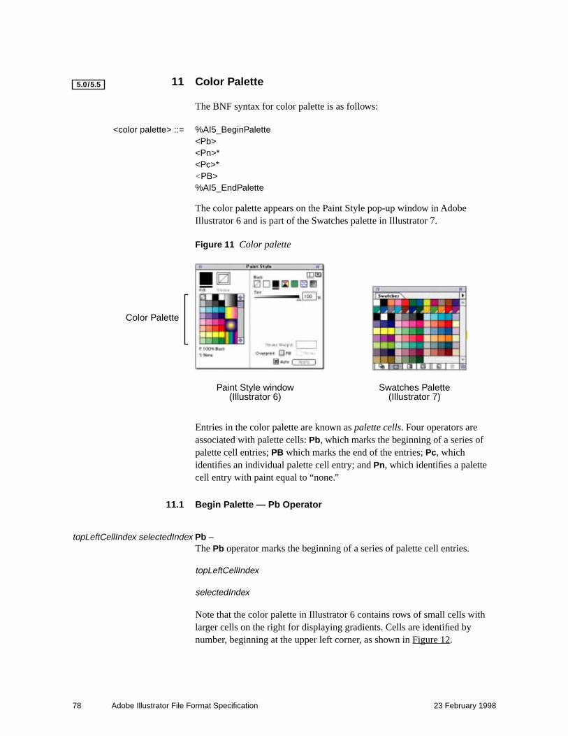
78 Adobe Illustrator File Format Specification 23 February 1998
11 Color Palette
The BNF syntax for color palette is as follows:
<color palette> ::= %AI5_BeginPalette<Pb><Pn>*<Pc>*<PB>%AI5_EndPalette
The color palette appears on the Paint Style pop-up window in Adobe Illustrator 6 and is part of the Swatches palette in Illustrator 7.
Figure 11 Color palette
Entries in the color palette are known as palette cells. Four operators are associated with palette cells: Pb, which marks the beginning of a series of palette cell entries; PB which marks the end of the entries; Pc, which identifies an individual palette cell entry; and Pn, which identifies a palette cell entry with paint equal to “none.”
11.1 Begin Palette — Pb Operator
topLeftCellIndex selectedIndex Pb –The Pb operator marks the beginning of a series of palette cell entries.
topLeftCellIndex
selectedIndex
Note that the color palette in Illustrator 6 contains rows of small cells with larger cells on the right for displaying gradients. Cells are identified by number, beginning at the upper left corner, as shown in Figure 12.
5.0/5.5
Color Palette
Paint Style window(Illustrator 6)
Swatches Palette(Illustrator 7)

11 Color Palette 79
Figure 12 Palette cell numbering, Illustrator 6
Gradients in palette cells are identified by their names and their local gradient instantiation attributes.
11.2 End Palette — PB Operator
– PB – The PB end palette operator marks the end of a series of palette cell entries.
11.2.1 Palette Cell — Pc Operator
– Pc – The Pc palette cell operator delimits each palette cell entry.
11.3 Palette Cell None — Pn Operator
– Pn – The Pn palette cell operator identifies a cell has having a paint value equal to “none.”
Gradients are defined in two separate parts. There’s the part in the header, which defines the color stops, etc. And then when it actually gets used in an object, there’s the transformation matrix, etc. that are arguments used when it’s attached to an object. That stuff is part of the <fill color> BNF definition.
The coordinate system. From the user’s point of view, when you run the program, there is an origin that is set to the bottom left corner of the art board, and it’s a first quadrant coordinate system. But there’s a translation that happens when you write out the coordinates into the file. If you zoom back on the image all the way, you see a larger canvas that represents the entire imageable artwork AI will allow. And that origin is in the upper left corner. So you’ll define a blend that, in the palette, has a (0,0) origin. But when you write out the file, you’ll see these coordinates with values in the thousands. That’s because the file is written in absolute coordinates relative to the upper left corner of the imageable space. You’ll see those numbers in files created by AI, but they’ll be ignored when AI reads a file. They’ll be recomputed when the gradient is actually applied.
0 1 2 3
4 5 6 78
9 10 11 12
13 14 16
…18
1715

80 Adobe Illustrator File Format Specification 23 February 1998
The following example shows part of the palette entry for the palette shown in Figure 11.
%AI5_BeginPalette
0 0 Pb % Begin palette cell entries, starting at upper left corner.Pn % Zeroth cell is color “none.”Pc % Begin a palette cell entry. First cell is black (gray scale of 1).1 g
Pc % Begin a palette cell entry. Second cell is white (gray scale of 0).0 g
Pc % Begin a palette cell entry.0 0 0 0 k % Third cell is process white (CMYK value of 0, 0, 0, 0).Pc % Fourth cell is 75% gray.0.75 g
...
Pc % Eighth cell is instance of Black & White gradient.Bb % Begin gradient.2 (Black & White) -4014 4716 0 0 1 0 0 1 0 0 Bg
0 BB % End gradient.Pc % Ninth cell is 25% Cyan.0.25 0 0 0 k
...
Pc
1 0.5 1 0 k
Pc % Pc operator follows last cell.PB % End palette operator.%AI5_EndPalette
Note that the xOrigin yOrigin arguments to the Bg operator in the above example are very large (–4014, 4716). These values have no meaning in gradient instances that are palette cell entries. The xOrigin and yOrigin arguments are recomputed when an instance of the gradient is used to fill an object.
Note also that white and black can be specified with two different color systems, gray scale or CMYK.

12 Attributes 81
12 Attributes
The attributes of an object are displayed in the pop-up window when the user asks for the attributes of a selected object. Attributes are maintained in the document file with the Ap and Ar operators.
Figure 13 Viewing object attributes
showCenter Ap – The Ap operator determines whether or not the center point of a path is displayed. By default, only rectangular (including square) and oval (including circular) paths have visible center points, but the center point of any path can be displayed by setting the value of the showCenter argument
showCenter 0 = do not show center point1 = show center point
resolution Ar – The Ar operator determines the accuracy with which a path is rendered on an output device. The value of resolution, in dots-per-inch (dpi), is used to calculate the argument to the setflat operator when an object is rendered in final form. See PostScript Language Reference Manual, Second Edition for a description of the setflat operator.
When a path is rendered in PostScript language, it is approximated by straight line segments. The value of resolution determines how finely the path is subdivided when Adobe Illustrator generates the printable PostScript file. The default resolution value of 800 dpi provides single-dot line segments on an 800 dpi output device. A value of 800 is typically sufficient for higher-resolution devices also (producing three-dot line segments on a 2400-dpi imagesetter, for example). Some objects, such as Kanji typeface characters, may require higher resolution (at the expense of increased rasterization times). Attributes are specific to objects, so paths that require higher resolution values can be set independently.
5.0/5.5

82 Adobe Illustrator File Format Specification 23 February 1998
Attributes are written to the document file only when they change. For example, if all paths in the document have a resolution of 800 dpi, the value 800 is only written once. If a single object in the document is assigned a different resolution, that resolution appears in the document in object paint order. The resolution is reset to 800 dpi for objects that follow the singular object in paint order.

13 Hyphenation Language — XL Operator 83
13 Hyphenation Language — XL Operator
Text hyphenation dictionaries appeared in Adobe Illustrator 5.5. The XL operator selects a dictionary to use for hyphenating text.
%_ languageID XL The %_ languageID argument to XL specifies a hyphenation dictionary. Languages are identified by number, as follows:
languageID 0 = U.S. English1 = U.K. English2 = French3 = German4 = Spanish5 = Dutch6 = Italian7 = Swedish8 = Norwegian9 = Finnish10 = Danish11 = Hungarian
5.0/5.5

84 Adobe Illustrator File Format Specification 23 February 1998
14 Nonprinting Elements
In general, nonprinting elements of documents are bracketed by comments and introduced by the Np operator, as follows:
%AI5_Begin_NonPrinting
Np
…object definition…%AI5_End_NonPrinting--
Nonprinting objects are stored in a document but are not printed because they are not assigned to an object. For example, gradients and patterns are not printed if they are not used to paint an object. Such objects are contained in revisable documents. When a revisable document is opened, the gradients and patterns that have been defined in it are available to the application even though no printable objects are using them.
When a document is in final form (a PostScript file ready to be printed), nonprinting objects are omitted.
Nonprinting layers are not identified by the Np operator. Instead, the printing argument to the Lp operator determines whether or not the layer is printable. See page 71 for details.
5.0/5.5

15 Text 85
15 Text
There are three kinds of text in Adobe Illustrator:
• Point text is neither bounded by a path nor on a path. It is created by clicking the type tool to create an insertion point, then typing. The first line of the text block begins at the insertion point. A carriage return determines the line breaks in point text.
• Area text is bounded by a path. It is created by clicking the type tool and dragging a rectangle, and then starting to type. You can also create area text by clicking a path, selecting the area type tool, and then typing. A single text object can contain multiple text area elements.
• Text on a path follows the shape of a path. It is created by clicking a the path-type tool on a path, then typing.
Text can overflow an area frame and thus not be visible on screen or when printed. Adobe Illustrator still saves such overflow text to the file, however. Linked areas allow text to flow from one area to another. Linked areas are part of the same text object.
Note You cannot link point text or path text to an area text object. All flowed text must appear in area texts.
Text can be invisible if you set its style to neither fill nor stroke. Such text is not rendered on the page, but Adobe Illustrator writes the text to the file with the same structure as if the text were rendered.
15.1 Revisable and Final-Form Text
Adobe Illustrator writes out two kinds of information about text: revisable information and final-form printing information. Revisable information consists of those settings the user makes and can examine in the various dialog boxes of Adobe Illustrator — font size, for example. Final-form information is regenerated by Adobe Illustrator once the file has been read — it primarily helps to print text properly. Final-form information consists of character positioning, text flow from line to line and area to area, and similar information. This section differentiates between revisable, required information and final-form information.
Note You can safely leave final-form information out of files and still have Adobe Illustrator read them correctly and regenerate the information; however, the file will not be an official EPS file and will not print.
Adobe Illustrator recalculates the values of all final-form operators after reading the file.

86 Adobe Illustrator File Format Specification 23 February 1998
15.2 Text Syntax Summary
The BNF syntax of text in Adobe Illustrator is as follows:
<text object> ::= <To><text at a point> |<text area> |<text along a path><TO>
<text at a point> ::= <Tp><TP><text run>+
<text area> ::= <text area element>+{<overflow text>}
<text area element> ::=<Tp><path object><TP><text run>+
<text along a path> ::= <Tp><path object><TP><text run>+{<overflow text>}*
<text run> ::= {<text style> |<paint style> |<text position> |<Tk>}*<text body>

15 Text 87
<text style> ::= <Tr> | (render mode)<Tf> | (font & size)<Ts> | (rise and fall)<Tz> | (text scaling)<Tt> | (tracking)<TA> | (automatic kerning)<TC> | (intercharacter spacing)<TW> | (interword spacing)<Ti> | (indents)<Ta> | (alignment)<Tq> | (hanging quotations)<Tl> | (leading)<TV> | (horizontal or vertical writing)<Tv> | (rotate characters 90°)<Ty> | (Kumi orientation)<TY> | (Kumi orientation, informational
only)<TG> | (line break)<Tg> | (binding punctuation)<Xu> (Japanese layout rules)
<text position> ::= (printing only)<Tc> | (computed intechar. spacing)<Tw> | (computed interword space)<Tm> | (text matrix)<Td> | (translate)<T*> | (translate down)<TR> (reset matrix; found only in
pattern prototypes)
<text body> ::= <Tx> | <Tj> | <T+> | <T–>
<overflow text> ::= {<text style> | <paint style> | <TK>}*<TX> | <T+>
15.3 Text Operators Summary
The following list of text operators identifies them as revisable or final-form. For a definition of these terms, see section 15.1 on page 85.
type To [Revisable] This operator begins a text object. The type argument take on one of the following values:
0 — point text1 — area text2 — path text
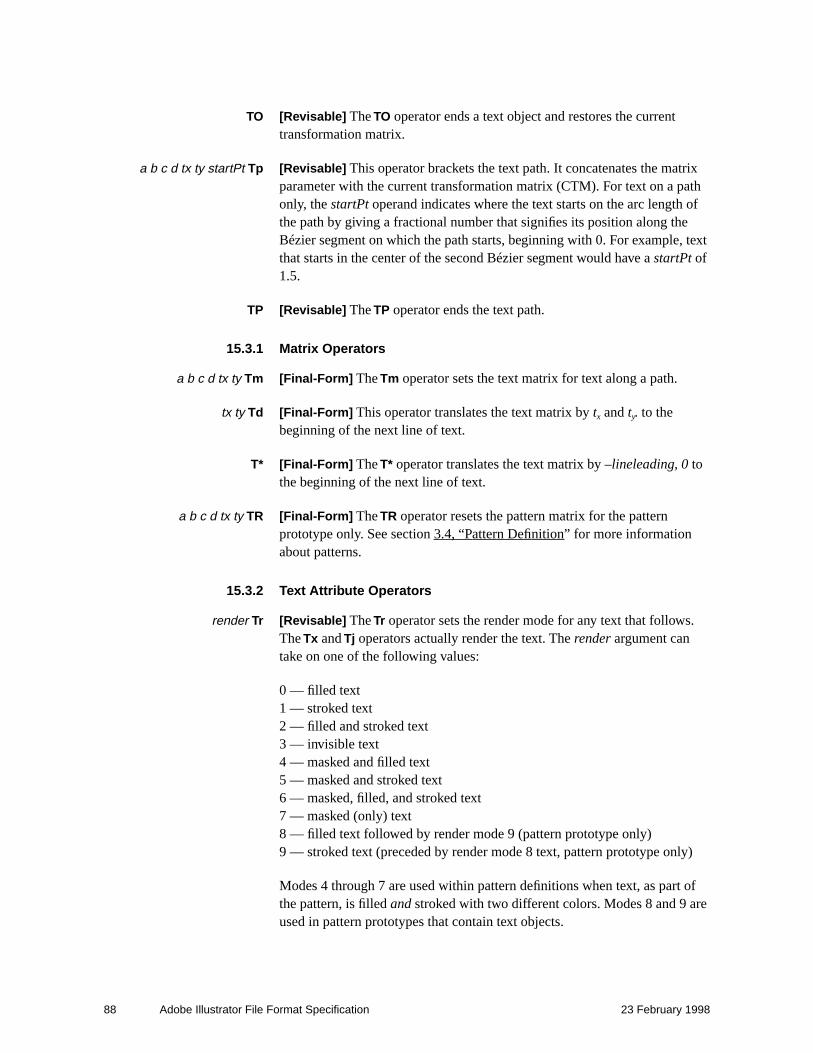
88 Adobe Illustrator File Format Specification 23 February 1998
TO [Revisable] The TO operator ends a text object and restores the current transformation matrix.
a b c d tx ty startPt Tp [Revisable] This operator brackets the text path. It concatenates the matrix parameter with the current transformation matrix (CTM). For text on a path only, the startPt operand indicates where the text starts on the arc length of the path by giving a fractional number that signifies its position along the Bézier segment on which the path starts, beginning with 0. For example, text that starts in the center of the second Bézier segment would have a startPt of 1.5.
TP [Revisable] The TP operator ends the text path.
15.3.1 Matrix Operators
a b c d tx ty Tm [Final-Form] The Tm operator sets the text matrix for text along a path.
tx ty Td [Final-Form] This operator translates the text matrix by tx and ty. to the beginning of the next line of text.
T* [Final-Form] The T* operator translates the text matrix by –lineleading, 0 to the beginning of the next line of text.
a b c d tx ty TR [Final-Form] The TR operator resets the pattern matrix for the pattern prototype only. See section 3.4, “Pattern Definition” for more information about patterns.
15.3.2 Text Attribute Operators
render Tr [Revisable] The Tr operator sets the render mode for any text that follows. The Tx and Tj operators actually render the text. The render argument can take on one of the following values:
0 — filled text1 — stroked text2 — filled and stroked text3 — invisible text4 — masked and filled text5 — masked and stroked text6 — masked, filled, and stroked text7 — masked (only) text8 — filled text followed by render mode 9 (pattern prototype only)9 — stroked text (preceded by render mode 8 text, pattern prototype only)
Modes 4 through 7 are used within pattern definitions when text, as part of the pattern, is filled and stroked with two different colors. Modes 8 and 9 are used in pattern prototypes that contain text objects.

15 Text 89
/_fontname size ascent descent Tf[Revisable] The Tf operator specifies the re-encoded name of the font to use and its size in points. The ascent and descent values are used when printing vertical text, but are ignored when being read by Adobe Illustrator.
The ascent and descent arguments were introduced with Adobe Illustrator 7.0.
alignment Ta [Revisable] The Ta operator sets text alignment both horizontally and vertically. The value for alignment can be one of the following:
0—left aligned1—center aligned2—right aligned3—justified (right and left)4—justified including last line
leading paragraphLeading Tl [Revisable] The Tl (lowercase L) operator sets the leading for the paragraph. The leading argument sets the leading between lines within a paragraph and the paragraphLeading argument sets the extra leading between paragraphs.
userTracking Tt [Revisable] The Tt operator sets additional space to add between characters in units of one thousandth of an em.
minSpace optSpace maxSpace TW[Revisable] The TW operator sets word spacing, where the minimum, optimum, and maximum space between words (the size of space characters) is expressed as a percentage of the width of a regular space character: 100 (100%) equals the width of one space character.
wordSpace Tw [Final-Form] The Tw operator sets computed word spacing.
minSpace optSpace maxSpace TC[Revisable] The TC operator sets character spacing, where the minimum, optimum, and maximum space between characters is expressed as a percentage of the width of a regular space character: 100 (100%) equals the width of one space character.
charSpace Tc [Final-Form] The Tc operator sets computed character spacing.
rise Ts [Revisable] The Ts operator sets the distance by which a character is raised above the baseline in superscripting and dropped below the baseline when subscripting. The argument rise is expressed in points.
7.0

90 Adobe Illustrator File Format Specification 23 February 1998
firstStartIndent otherStartIndent stopIndent Ti[Revisable] The Ti operator sets the indentation of a paragraph. The argument otherStartIndent specifies the indentation for the left side of the paragraph, firstStartIndent specifies a delta from the left side that applies only to the first line, and stopIndent specifies any right side indentation. The three arguments are specified in points.
autoKern TA [Revisable] The TA operator specifies whether to use pairwise kerning. Adobe Illustrator uses the kerning pairs built into the Type 1 font program. If the autoKern argument is 0, Adobe Illustrator uses no pair kerning; if the autoKern argument is 1, Adobe Illustrator does use pair kerning.
hangingQuotes Tq [Revisable] The Tq operator determines whether a run of text uses hanging quotation marks; a hanging quotation mark is one that extends beyond the left or right edge of the text block. If the hangingQuotes argument is 0, Adobe Illustrator does not use hanging quotation marks; if the argument is 1, it does. For the domestic version of Adobe Illustrator, the marks which hang are: period, comma, semicolon, colon, backquote, left and right single quotes, left and right double quotes, dash, en-dash, em-dash. That is:
. , ; : ` ‘ ’ “ ” - – —
Note Marks may be different for international editions.
15.3.3 Text Body Operators
textString Tx [Revisable] The Tx operator renders the text associated with a path object. The text is not justified. The textString argument is a string of text: any series of ASCII codes in the native platform encoding. The character combination \r in the string signifies a new paragraph.
textString Tj [Revisable] The Tj operator is identical to the Tx operator except that it renders a string of justified text.
textString TX [Revisable] Text that overflows the text area (invisible). Equivalent to the Tx operator.
autoKern kernValue Tk [Revisable] The Tk operator produces kerned text. An autoKern value of 0 indicates manual kerning; a value of 1 indicates automatic kerning. The kernValue operand sets a kerning value in units of one thousandth of an em. When autoKern is 0, Adobe Illustrator uses the value in kernValue; when autoKern is 1, Adobe Illustrator uses the built-in kerning pairs.
autoKern kernValue TK [Revisable] The TK operator is the same as the Tk operator, except that it applies to overflow text (invisible).

15 Text 91
T+ [Revisable] The T+ operator appears before or after a text run. When it appears after a text run, it indicates that a non-printing discretionary hyphen occurs after the text run; when it appears before a text run, it indicates that a non-printing discretionary hyphen occurs before the text run.
T– [Revisable] The T– operator is similar to the T+ operator, but it indicates that the last character in the preceding text run was a printed discretionary hyphen.
15.3.4 Far-Eastern Text Operators
direction TV [Revisable] The TV operator indicates whether the writing is horizontal or vertical. The default direction value of 0 indicates horizontal writing; 1 indicates vertical writing.
Although this operator is documented as part of Adobe Illustrator 6.0 file format, non-Japanese versions prior to Illustrator 7.0 post an error when they encounter this operator. The TV operator should be considered part of Adobe Illustrator 7.0 (and later) format only.
rotation Tv [Revisable] The Tv operator indicates whether or not Roman characters are rotated 90 degrees within vertical text. The default rotation value 0 rotates text 90 degrees clockwise in vertical writing. A rotation value of 1 indicates non-rotated text, with the result that Roman characters appear in the same orientation for both vertical and horizontal writing.
Although the Tv operator is documented as part of Adobe Illustrator 6.0 file format, non-Japanese versions prior to Illustrator 7.0 post an error when they encounter this operator. The Tv operator should be considered part of Illustrator 7.0 (and later) format only. Illustrator 7.0 can draw Far Eastern characters on any system where the necessary Chinese, Japanese, or Korean fonts are installed. These fonts are collectively called CJK fonts.
If a file contains CJK characters but does not contain a Tv or TV operator, then the file will read into non-CJK versions of Adobe Illustrator (prior to version 7.0) successfully, but any CJK characters in the file will appear as gibberish. If a file does contain a Tv or TV operator and is opened in a non-CJK version of Illustrator earlier than version 5.0, Illustrator will produce an error message when it attempts to open the file. Therefore, if you are concerned with maximum compatibility and are not concerned with vertical text, do not place Tv or TV operators into output files; if you do want to offer vertical text, give users a choice of writing either Roman or CJK output for compatibility with non-CJK versions of Illustrator earlier than version 7.0.
bindrepeat Tg [Revisable] The Tg operator controls binding punctuation and the repeat character. The bindrepeat argument can assume one of the following four values:
7.0
7.0
7.0

92 Adobe Illustrator File Format Specification 23 February 1998
0 — binding punctuation off, repeat character off.1 — binding punctuation on, repeat character off.2 — binding punctuation off, repeat character on.3 — binding punctuation on, repeat character on.
linebreak TG [Revisable] The TG operator records the user-supplied value of the “Line Breaking” text field in the Paragraph palette. The value of linebreak is an integer between zero and 100, representing percent.
%_prop cjkLayout cjkRoman cjkCjk TuJapanese layout rules — See Xu.
kumi Ty [Revisable] Pairs of Ty operators mark the beginning and end of text set in Kumi orientation. In a vertical text layout, Kumi text is oriented horizontally. European language words and numbers are often represented in Kumi text layout. The value of kumi determines whether Ty marks the beginning or end of Kumi text:
1—begin Kumi text block.0—end Kumi text block.
The text bracketed by “1 Ty” and “0 Ty” behaves as though horizontal text (“0 TV”) were specified.
kumi TY [Revisable] As with the Ty operator, pairs of TY operators mark the beginning and end of text set in Kumi orientation. TY is used when Kumi orientation does not appear in set text, but must be recorded for later use. For example, when a Kumi text block is identified in a line of horizontal text, all the text is set horizontally and the Kumi attribute is ignored. TY allows the Kumi attribute to be saved in the file and applied automatically if and when the main body of horizontal text is later set vertically.
The value of kumi determines whether TY marks the beginning or end of Kumi text:
1—begin Kumi text block.0—end Kumi text block.
%_prop cjkLayout cjkRoman cjkCjk Xu[Revisable] The Xu operator specifies Japanese language layout rules. This operator is internally represented as Tu but externally as Xu so that older versions of Adobe Illustrator will ignore it.
The parameters represent user settings in the Character palette for Japanese Layout rules:
prop 0—Proportional CJK off.1—Proportional CJK on (box checked).
cjkLayout 0—Japanese Layout Rules off.1—Japanese Layout Rules on (box checked).
cjkRoman CJK/Roman user-entered value, 0 ≤ cjkRoman ≤ 200.cjkCjk CJK/CJK user-entered value, 0 ≤ cjkCjk ≤ 200.
7.0
7.0
7.0
7.0
7.0

15 Text 93
15.4 Text Operator Details
This section explains more about text in Adobe Illustrator and provides details of how text operators are used.
15.4.1 Text Attributes
A text attribute is a quality of the text such as font, justification, stroke, or fill. There are three kinds of text attribute used in Adobe Illustrator: character style, paragraph style, and paint style (see section 5.2, “Paint Style”).
A character attribute is an attribute such as font size or scale that pertains to one or more characters. A paragraph attribute pertains to one or more paragraphs, and includes details such as justification and indentation. A paint style attribute pertains to any set of characters that all have the same paint style and character attributes (called a text run). The Adobe Illustrator user interface lets users apply any kind of paint style to characters—stroke or fill, stroke width changes, dashed lines, and so forth.
15.4.2 Wraparound Text
Area text objects can also be grouped with paths lying on top so that the text in the text objects “wraps” around (or avoids) the paths. The BNF syntax for wraparound text is
<wraparound group> ::= <*w>{<object>}*{<wraparound objects>}*<*W>
<wraparound objects> ::= <text object> |{<object>}*
15.4.2.1 Wraparound Text Operators
Wraparound text begins with the *w operator. Zero or more objects follow, then a standard Adobe Illustrator text object follows, and is in turn followed by zero or more Adobe Illustrator graphic objects around which the text will wrap. The wraparound text group ends with the *W operator.
15.4.3 Text Objects
A text object is bracketed by the To and the TO operators. The To operator begins a text object, and the TO operator ends it. Between the two can appear a series of operators that control the text path(s), set the text matrix, and set various other text attributes. The syntax for a text object is

94 Adobe Illustrator File Format Specification 23 February 1998
<text object> ::= <To><text at a point> |<text area> |<text along a path><TO>
Attributes are modal, that is, once an attribute operator has made a change, that change stays in force until changed again. While there is no special order in which the operators must appear, because of modality, operator order may have a bearing on the end result. See section 15.2, “Text Syntax Summary” for information about operator order.
Note If the Adobe Illustrator file includes more than one path between the To and TO delimiters, it must be area text; it means that text can flow from one object to another.
15.4.3.1 Text Object Operators
type To [Revisable] This operator begins a text object. The type argument can be one of:
0 point text1 area text2 path text
TO [Revisable] The TO operator ends a text object and restores the current transformation matrix.
15.4.4 Text Paths
A text path is a combination of the current transformation matrix and the path geometry of a text container—an area or object such as a box, circle, or other shape.
Within a text object, each text path is bracketed by the Tp and TP operators. The Tp operator takes as its arguments a transformation matrix and a start point. The Tp and TP operators appear in every kind of text object. Its purpose is to provide a matrix for the text object and its container (if any). The operators vary in their use depending on text type.
15.4.4.1 Text Path Operators
Syntax for the text path operators Tp and TP is:

15 Text 95
a b c d tx ty startPt Tp [Revisable] This operator brackets the text path. It concatenates the matrix parameter with the current transformation matrix (CTM). For text on a path only, the startPt operand indicates where the text starts on the arc length of the path by giving a fractional number that signifies its position along the Bézier segment on which the path starts, beginning with 0. For example, text that starts in the center of the second Bézier segment would have a startPt of 1.5.
TP [Revisable] The TP operator ends the text path.
15.4.5 Text Rendering
Text rendering mode is set by a call to the Tr operator. This operator takes as its argument one of the selectors in Table 12. The Tx (non-justified text) and Tj (justified text) operators actually render the text.
Table 12 Text rendering modes
Selector Rendering Mode
0 fill text
1 stroke text
2 fill and stroke text
3 text with no fill and no stroke (“invisible”)
4 mask and fill text
5 mask and stroke text
6 mask, fill, and stroke
7 mask (only) text
8 filled text followed by rendertype 9(pattern prototype only)
9 stroked text preceded by render mode 8 text(pattern prototype only)
15.4.5.1 Text Rendering Operators
The text rendering operator descriptions are:
render Tr [Revisable] The Tr operator sets the render mode for any text that follows. The Tx and Tj operators actually render the text. The render argument can be one of the following values:
0—fill text1—stroke text2—fill and stroke text

96 Adobe Illustrator File Format Specification 23 February 1998
3—invisible text4—mask and fill text5—mask and stroke text6—mask, fill, and stroke text7—mask (only) text8—filled text followed by render mode 9 (pattern prototype only)9—stroked text (preceded by render mode 8 text, pattern prototype only)
Modes 4 through 7 are used within pattern definitions when text, as part of the pattern, is filled and stroked with two different colors. Modes 8 and 9 are used in pattern prototypes that contain text objects.
textString Tx [Revisable] The Tx operator renders the text associated with a path object. The text is not justified. The textString argument is a string of text: any series of ASCII codes in the native platform encoding. The character combination \r in the string signifies a new paragraph.
textString Tj [Revisable] The Tj operator is identical to the Tx operator except that it renders a string of justified text.
15.4.6 Kerning
Adobe Illustrator offers two types of kerning. These are:
• Track kerning (Tt). The specified amount of space is added between each pair of characters. Space is measured in thousandths of an em.
• Pairwise kerning (TA, Tk, TK). The TA (automatic kerning) operator tells Adobe Illustrator to turn automatic kerning on and use the kerning pairs specified in the font program itself. The Tk operator also produces kerned text, either manual or automatic, depending on the value of one of its operands. Manual kerning overrides automatic kerning. Users can specify manual kerning in thousandths of an em. The TK operator is identical to the Tk operator, but applies to overflow text that is not displayed or printed.
Kerning operators help set the style of text runs and overflow text. The BNF syntax for kerning operators is:
<text run> ::= {<text style> |<paint style> |<text position> |<Tk>}*<text body>
<overflow text> ::= {<text style> | <paint style> | <TK>}*<TX> | <T+>

15 Text 97
<text style> ::= <Tr> | (render mode)<Tf> | (font & size)<Ts> | (rise and fall)<Tz> | (text scaling)<Tt> | (tracking)<TA> | (automatic kerning)<TC> | (intercharacter spacing)<TW> | (interword spacing)<Ti> | (indents)<Ta> | (alignment)<Tq> | (hanging quotations)<Tl> | (leading)<TV> | (horizontal or vertical writing)<Tv> | (rotate characters 90°)<Ty> | (Kumi orientation)<TY> | (Kumi orientation, informational
only)<TG> | (line break)<Tg> | (binding punctuation)<Xu> (Japanese layout rules)
15.4.6.1 Kerning Operators
The text kerning operator descriptions are:
userTracking Tt [Revisable] The Tt operator sets additional space to add between characters in units of one thousandth of an em.
autoKern TA [Revisable] The TA operator specifies whether to use pairwise kerning. Adobe Illustrator uses the kerning pairs built into the Type 1 font program. If the autoKern argument is 0, Adobe Illustrator uses no pair kerning; if the autoKern argument is 1, Adobe Illustrator does use pair kerning.
autoKern kernValue Tk [Revisable] The Tk operator produces kerned text. An autoKern value of 0 indicates manual kerning; a value of 1 indicates automatic kerning. The kernValue operand sets a kerning value in units of one thousandth of an em. When autoKern is 0, Adobe Illustrator uses the value in kernValue; when autoKern is 1, Adobe Illustrator uses the built-in kerning pairs.
autoKern kernValue TK [Revisable] The TK operator is the same as the Tk operator, except that it applies to overflow text (invisible).
15.4.7 Spacing
Text spacing for both justified and non-justified text is controlled by spacing control operators. Word spacing and character spacing are controlled independently. For justified text, minimum, optimum, and maximum spacing can be specified; for non-justified text, only the optimum value is used.

98 Adobe Illustrator File Format Specification 23 February 1998
• Word spacing (TW). Specifies the minimum, optimum, and maximum space between words (added to space characters). Measurement is in a percentage of the width of a regular space character.
• Character spacing (TC). Specifies the minimum, optimum, and maximum space between characters in the file. Measurement is in a percentage of the width of a regular space character.
Two other spacing operators also appear in Adobe Illustrator files. They are final-form.
• Computed word spacing (Tw). This is the actual word spacing for a particular line of text. It is recomputed on a per-line basis.
• Computed character spacing (Tc). This is the actual character spacing for a particular line of text. It is recomputed on a per-line basis.
Spacing operators apply to text style and position. The BNF syntax for spacing operators is:
<text style> ::= <Tr> | (render mode)<Tf> | (font & size)<Ts> | (rise and fall)<Tz> | (text scaling)<Tt> | (tracking)<TA> | (automatic kerning)<TC> | (intercharacter spacing)<TW> | (interword spacing)<Ti> | (indents)<Ta> | (alignment)<Tq> | (hanging quotations)<Tl> | (leading)<TV> | (horizontal or vertical writing)<Tv> | (rotate characters 90°)<Ty> | (Kumi orientation)<TY> | (Kumi orientation, informational
only)<TG> | (line break)<Tg> | (binding punctuation)<Xu> (Japanese layout rules)
<text position> ::= (printing only)<Tc> | (computed intechar. spacing)<Tw> | (computed interword space)<Tm> | (text matrix)<Td> | (translate)<T*> | (translate down)<TR> (reset matrix; found only in pattern prototypes)

15 Text 99
15.4.7.1 Spacing Operators
The text spacing operator descriptions are:
minSpace optSpace maxSpace TW[Revisable] The TW operator sets word spacing, where the minimum, optimum, and maximum space between words (the size of space characters) is expressed as a percentage of the width of a regular space character: 100 (100%) equals the width of one space character.
wordSpace Tw [Final-Form] The Tw operator sets computed word spacing.
minSpace optSpace maxSpace TC[Revisable] The TC operator sets character spacing, where the minimum, optimum, and maximum space between characters is expressed as a percentage of the width of a regular space character: 100 (100%) equals the width of one space character.
charSpace Tc [Final-Form] The Tc operator sets computed char spacing.
15.4.8 Line and Paragraph Leading
Line and paragraph leading (spacing) is set using the Tl (lowercase L) operator, in units of one thousandth of an em-square. The BNF syntax for the leading operator applies to text style:
<text style> ::= <Tr> | (render mode)<Tf> | (font & size)<Ts> | (rise and fall)<Tz> | (text scaling)<Tt> | (tracking)<TA> | (automatic kerning)<TC> | (intercharacter spacing)<TW> | (interword spacing)<Ti> | (indents)<Ta> | (alignment)<Tq> | (hanging quotations)<Tl> | (leading)<TV> | (horizontal or vertical writing)<Tv> | (rotate characters 90°)<Ty> | (Kumi orientation)<TY> | (Kumi orientation, informational
only)<TG> | (line break)<Tg> | (binding punctuation)<Xu> (Japanese layout rules)

100 Adobe Illustrator File Format Specification 23 February 1998
15.4.8.1 Leading Operator
The leading operator description is:
leading paragraphLeading Tl [Revisable] The Tl (lowercase L) operator sets the leading for the paragraph. The leading argument sets the leading between lines within a paragraph and the paragraphLeading argument sets the extra leading between paragraphs.
15.4.9 Superscripting and Subscripting
Superscripting and subscripting are set using the Ts operator with (respectively) positive and negative values expressed in points. The BNF syntax for the Ts operator applies to text style:
<text style> ::= <Tr> | (render mode)<Tf> | (font & size)<Ts> | (rise and fall)<Tz> | (text scaling)<Tt> | (tracking)<TA> | (automatic kerning)<TC> | (intercharacter spacing)<TW> | (interword spacing)<Ti> | (indents)<Ta> | (alignment)<Tq> | (hanging quotations)<Tl> | (leading)<TV> | (horizontal or vertical writing)<Tv> | (rotate characters 90°)<Ty> | (Kumi orientation)<TY> | (Kumi orientation, informational
only)<TG> | (line break)<Tg> | (binding punctuation)<Xu> (Japanese layout rules)
15.4.9.1 Superscripting and Subscripting Operator
The superscripting and subscripting operator description is:
rise Ts [Revisable] The Ts operator sets the distance by which a character is raised above the baseline in superscripting and dropped below the baseline when subscripting. The argument rise is expressed in positive or negative points.
15.4.10 Discretionary Hyphens
The T+ operator appears whenever the user has inserted a discretionary hyphen.

15 Text 101
The T– operator appears in text wherever a discretionary hyphen prints.
The discretionary hyphen operators apply to body text; because overflow text does not print, only the T+ operator applies to overflow text. The BNF summary for the discretionary hyphen operators is:
<text body> ::= <Tx> | <Tj> | <T+> | <T–>
<overflow text> ::= {<text style> | <paint style> | <TK>}*<TX> | <T+>
15.4.10.1 Discretionary Hyphen Operators
The discretionary hyphen operator descriptions are:
T+ [Revisable] The T+ operator appears before or after a text run. When it appears after a text run, it indicates that a non-printing discretionary hyphen occurs after the text run; when it appears before a text run, it indicates that a non-printing discretionary hyphen occurs before the text run.
T– [Revisable] The T– operator is similar to the T+ operator, but it indicates that the last character in the preceding text run was a printed discretionary hyphen.
15.4.11 Alignment and Justification
The Ta operator sets text alignment: left, centered, right, or justified.
The Ti (lowercase i) operator controls line indentation. It takes arguments that state the values of the left indent, a delta from the left indent for the first line, and a right indent in points.
The Tz operator condenses or expands the horizontal scaling of a character as a percentage of the regular font size.
A group of characters that share the same size, paint style, tracking, and so forth can be written out as a single call to one of the text rendering operators: Tx (for non-justified text) or Tj (for justified text). See page 96 for a description of the text rendering operators.
The alignment and justification operators apply to text style. The BNF summary is:

102 Adobe Illustrator File Format Specification 23 February 1998
<text style> ::= <Tr> | (render mode)<Tf> | (font & size)<Ts> | (rise and fall)<Tz> | (text scaling)<Tt> | (tracking)<TA> | (automatic kerning)<TC> | (intercharacter spacing)<TW> | (interword spacing)<Ti> | (indents)<Ta> | (alignment)<Tq> | (hanging quotations)<Tl> | (leading)<TV> | (horizontal or vertical writing)<Tv> | (rotate characters 90°)<Ty> | (Kumi orientation)<TY> | (Kumi orientation, informational
only)<TG> | (line break)<Tg> | (binding punctuation)<Xu> (Japanese layout rules)
15.4.11.1 Alignment and Justification Operators
The alignment and justification operator descriptions are:
alignment Ta [Revisable] The Ta operator sets text alignment both horizontally and vertically. The value for alignment can be one of the following:
0—left aligned1—center aligned2—right aligned3—justified (right and left)4—justified including last line
firstStartIndent otherStartIndent stopIndent Ti[Revisable] The Ti operator sets the indentation of a paragraph. The argument otherStartIndent specifies the indentation for the left side of the paragraph, firstStartIndent specifies a delta from the left side that applies only to the first line, and stopIndent specifies any right side indentation. The three arguments are specified in points.

15 Text 103
For rotated paragraphs, the indentation is calculated from the invisible rotated margins of the paragraph:
parallelScale perpendicularScale Tz[Revisable] The Tz operator sets the scaling of a line of text in the horizontal and vertical directions by condensing or expanding the line in terms of a percentage of the normal font width or height. The values of parallelScale and perpendicularScale determine the scale factors, as set by user input in Adobe Illustrator:
parallelScale scaling factor parallel to text line (right scaling field in Character palette).
perpendicularScalescaling factor perpendicular to text line (left scaling field in Character palette).
The Tz operator is present in earlier versions of Adobe Illustrator, but was modified to accommodate vertical text in version 7.0
15.4.12 Setting Far-Eastern Fonts
Adobe Illustrator supports Far-Eastern fonts such as Kanji that use the 83PVRKSJ–H encoding. You can set the type in these fonts both horizontally and vertically. Far-Eastern fonts are sometimes called CJK (Chinese-Japanese-Korean) fonts.
15.4.12.1 Setting Horizontal Type in Far-Eastern Text
If you are only concerned with supporting Far-Eastern text in the horizontal writing direction, set the type with one of the operators used for setting Roman fonts, but be sure to call out the Far-Eastern font with its PostScript font name and the 83PVRKSJ–H suffix. Then, in the character string, use the appropriate two-byte character combinations for the Far-Eastern characters you wish to show, based on the 83PVRKSJ–H encoding.
15.5 Text Examples
The following examples illustrate the operators used in point text, text on a path, and area text.
θ
The quick brown
fox jumped …
= rotation angle
rotatedmargins
7.0
Japan 7.0

104 Adobe Illustrator File Format Specification 23 February 1998
15.5.1 Point Text
In point text, there is no path geometry. The Tp operator simply passes the matrix that is associated with the object.
<text at a point> ::= <Tp><TP><text run>+
For example,
1 0 0 1 103.5 688.5 0 Tp
TP
0 Tr
0 O
0 g
800 Ar
0 J 0 j 1 w 4 M []0 d
%AI3_Note:
0 D
0 XR
/_Helvetica 12 Tf
0 Ts
100 Tz
0 Tt
1 TA
%_ 0 XL
36 0 Xb
XB
0 0 5 TC
100 100 200 TW
0 0 0 Ti
0 Ta
0 0 2 2 3 Th
0 Tq
0 0 Tl
0 Tc
0 Tw
(This is point text) Tx
(\r) TX
15.5.2 Text on a Path
For text on a path, there is no path geometry for the text. The entire text path is rotated (skewed, etc.). The actual path is bracketed inside Tp and TP. The startPt parameter is used only for text on a path. It indicates where the text starts on the path using a decimal number. The integer portion of the number is the Bézier segment on which the text start is located. The fractional part of the number represents the position at which the text begins on that segment.

15 Text 105
For example, text that starts in the center of the second of two Bézier segments would have a startPt of 1.5.
The BNF syntax for text along a path is
<text along a path> ::= <Tp><path object><TP><text run>+{<overflow text>}*
For example,
-1 0 0 -1 -4014 4716 0.0675 Tp
202.899 374.25 m
230.4305 374.25 286.5 399.9684 286.5 427.5 c
N
TP
0.9885 0.151 -0.151 0.9885 208.4129 374.4603 Tm
0 Tr
0 O
0 g
(T) Tx
0.9734 0.2289 -0.2289 0.9734 216.1119 375.6829 Tm
(h) Tx
0.9628 0.27 -0.27 0.9628 222.833 377.3146 Tm
(i) Tx
0.9527 0.3039 -0.3039 0.9527 225.6023 378.0656 Tm
(s) Tx
0.9338 0.3578 -0.3578 0.9338 234.7611 381.1499 Tm
(i) Tx
0.9223 0.3865 -0.3865 0.9223 237.4237 382.1454 Tm
(s) Tx
0.8931 0.4499 -0.4499 0.8931 246.3572 386.0144 Tm
(p) Tx
0.8685 0.4957 -0.4957 0.8685 252.5786 389.1538 Tm
(a) Tx
0.8463 0.5326 -0.5326 0.8463 258.563 392.6147 Tm
(t) Tx
0.8195 0.573 -0.573 0.8195 261.6362 394.5058 Tm
(h) Tx
0.7585 0.6516 -0.6516 0.7585 270.1332 400.7589 Tm
(t) Tx
0.7057 0.7085 -0.7085 0.7057 273.0183 403.1636 Tm
(e) Tx
0.6048 0.7964 -0.7964 0.6048 278.2454 408.4813 Tm
(x) Tx
0.4877 0.873 -0.873 0.4877 282.2554 413.9789 Tm
(t) Tx
Text
Bézier curve 0
Bézier curve 1

106 Adobe Illustrator File Format Specification 23 February 1998
(This is path text) TX
(\r) TX
15.5.3 Area Text
In area text, each container that text flows into has its own Tp and TP pair and matrix associated with it. The container also includes information about stroke and fill for the container. The BNF syntax for area text is
<text area> ::= <text area element>+{<overflow text>}
<text area element> ::= <Tp><path object><TP><text run>+
For example,
1 0 0 1 193.5442 586.4558 0 Tp
1 Ap
219 535.5442 m
233.0587 535.5442 244.4558 546.9413 244.4558 561 c
244.4558 575.0587 233.0587 586.4558 219 586.4558 c
204.9413 586.4558 193.5442 575.0587 193.5442 561 c
193.5442 546.9413 204.9413 535.5442 219 535.5442 c
n
TP
9.9899 -10.875 Td
0 Tr
0 O
0 g
(Area ) Tx
-7.3206 -14.5 Td
(text in a ) Tx
3.8921 -14.5 Td
(circle) Tx
(\r) TX
A text area element within a text object may be arbitrarily scaled, skewed, rotated, and translated using matrix operators. Text attributes such as whether the text is filled or stroked, its kerning and leading are controlled by attribute operators.
Adobe Illustrator has three text matrix handling operators that control where to place the text object. For text on a path, the Tm operator sets the text matrix. The Td and T* operators translate the text matrix to the start of the next line of text.
However, the three text matrix operators are final-form. Adobe Illustrator writes this information when it saves a file but ignores it when reading the file.
16 Placed Art 107
16 Placed Art
The BNF syntax for placing an EPS file into an Adobe Illustrator document is
<placed art object> ::= <'><art reference><~>
<art reference> ::= <file reference> | <file inline>
<file reference> ::= %%IncludeFile: <filename>
<file inline> ::= %%BeginDocument:<filename>… included file contents%%EndDocument
<filename> ::= platform-specific path name of file
<subscriber object> ::= %AI3_Subscriber:<subscriber ID><placed art object>
<subscriber ID> ::= resource number of SECT resource in file
16.1 Placed Art Operators
The placed art operator identifies a document to import into the illustration. The syntax for the placed art operator is as follows:
[a b c d tx ty] llx lly urx ury (filename) 'The ' (single quote or tick-mark) operator specifies that the document stored in filename is to be imported into the illustration. The imported file is assumed to be an EPS-conforming document.
The filename string is the full pathname for the file in the operating system’s file system. Adobe Illustrator concatenates the matrix operand with the current transformation matrix to establish a new user space and an origin for the imported document. See PostScript Language Reference Manual, Second Edition for more information about transformation matrices. The matrix handles any rotation and reflection to be applied to the imported document. The llx lly urx ury operands specify the bounding box from the imported document as stated by the %%BoundingBox comment in the imported document’s prolog.

108 Adobe Illustrator File Format Specification 23 February 1998
The ' operator establishes a new user space and sets values for graphic elements of the graph, equivalent to the following series of operators:
false setoverprint
0 setgray
0 setlinecap
1 setlinewidth
0 setlinejoin
10 setmiterlimit
[ ] 0 setdash
newpath
– ~ The ~ operator restores the user space in effect when the preceding ' operator was executed.
16.2 Placed Art Comments
The filename in the %%IncludeFile comment must be the same as that specified for the ' (single tick-mark) operator. This includes a file by reference in a given Adobe Illustrator document.
You can also save included files directly (rather than by reference) in an Adobe Illustrator EPS document. If you wish to do that, replace the %%IncludeFile comment with the following structure:
%%BeginDocument: filename
… put included file here …
%%EndDocument
Note Although useful for including files in EPS files, the usage shown above is not part of the Adobe Illustrator file format, and is not recommended.
Adobe Illustrator automatically modifies the %%DocumentFonts , %%CustomColors , and %%DocumentFiles comments of the including document to add information to the corresponding comments of an included document.
The %%AI3_subscriber comment concerns the Macintosh publish and subscribe facility available in System 7. It reads in an edition which has been published as graphics. The section ID shows the resource ID of the section (in a sect resource), as stored in the file. See Inside Macintosh Volume VI for more information on publish and subscribe. If you need to use this feature, you will also need to store the bounds in a bnds resource of the given id (whose format is a rectangle of Fixed values: left, top, right, bottom), and the section options in a psop resource of the given id (whose format is a two-byte integer, value 0).

17 Graphs 109
17 Graphs
The Adobe Illustrator graphs capability builds business graphs, such as bar (column) graphs and pie charts. Users can build such graphs using the application’s general drawing abilities, but having Adobe Illustrator itself build the graphs from numerical data helps assure accuracy.
The Gs operator begins a graph and the GS operator ends it. All graph operators consist of two characters and begin with G.
A graph in an Adobe Illustrator file has two parts: the functional specification and the objects that make up the graph. The functional spec acts like an internal header; it contains information about the graph, such as graph type, axis parameters, and graph data values. The graph objects are regular Adobe Illustrator path and text objects, which allows the file to be incorporated as an EPS file in other files for documents.
On command, Adobe Illustrator can recreate a graph based only on the functional spec. However, on reading an Adobe Illustrator file that contains a graph, Adobe Illustrator does not automatically recalculate the graph. Instead, it displays the graph objects as they appear in the file—exactly as Adobe Illustrator would treat any other objects in a file.
Note When preparing files that contain graphs for use with Adobe Illustrator, you must make sure that the functional spec matches the graph objects (if you choose to supply them). Otherwise, recalculating will result in changes to the graph.
The functional spec is most useful for writing graph information that Adobe Illustrator can understand, not for reading graph objects that have been produced by Adobe Illustrator. The functional spec is presented in Appendix A on page 145.
17.1 Syntax
The syntax of the graph section is:
<graph object> ::= <Gs><graph functional spec>{<graph customizations>}<graph group object><GS>

110 Adobe Illustrator File Format Specification 23 February 1998
<graph functional spec> ::=<graph size and dialog values>{<graph subscriptions>}<graph axis><graph axis><graph axis><graph table specs>
<graph size and dialog values> ::=<Gb><Gy><Gd>
<graph axis> ::= <Ga><GA>
<graph table specs> ::={<Gw>}*<Gz><Gc>+<GC>
<graph customizations> ::=<Gt>{<graph customization>}*<GT>
<graph customization> ::={<graph customization operator>}*<GX> | <Gg>{<Gv>}
<graph customization operator> ::={<Gm>}{<Gf>}{<Gy>}{<GD>}{<Ge>}{<G1>} (gee-one){<Gi>}{<Gl>} (gee-ell){<Gp>}{<Gx>}{<Gr>}{<G+>}{<Gg>}{<A>}{<paint style>}*{<text style>}
<graph subscriptions> ::=<Gj>

17 Graphs 111
<graph group object> ::=<u>{<graph rendered object>}*<U>
<graph rendered object> ::=<object> | <graph group object>{<Go>}
17.2 Graph Objects
Graph objects make up the second part of the graph. When Adobe Illustrator loads a file containing a graph, it draws the objects as described by this section without referring to the functional specification (at will, a user can tell Adobe Illustrator to recalculate the graph based on the functional spec).
Graph objects are essentially standard Adobe Illustrator objects, use Adobe Illustrator operators for their construction, and are subject to the current paint, fill, and stroke styles and the rest of the cumulative settings of the graphics state. However, in order to allow efficient editing of graphs, Adobe Illustrator uses a particular hierarchical grouping organization in memory. This has two effects on the file.
• Each graph object is followed by the Go operator, which tells Adobe Illustrator what that object is—data point, legend, axis, and so forth.
• Graph objects are grouped in a way representing their hierarchy in memory using the u and U operators (just as with other Adobe Illustrator grouped objects). Because this grouping represents a data structure, there may be in the file one or more “empty” groups of u followed immediately by U; there may even be nested empty groups.
Note When constructing an Adobe Illustrator file external to Adobe Illustrator which contains a graph, you must make sure that the organization of the empty groups is followed accurately.
17.2.1 Organization of Graph Objects
Table 13 shows the hierarchical organization of graph objects. Each group is bounded by the u and U operators.

112 Adobe Illustrator File Format Specification 23 February 1998
Table 13 Graph Object Organization
Left Axis groupRight Axis groupLegend groupCategory Axis groupData
Series 0Legend boxData series 0
Series 1Legend boxData series 1
Series nLegend boxData series n
Axis
17.2.2 Graph Object Operators
target column row whichAxis GoAfter each object that represents a major part of the graph, Adobe Illustrator must identify it: which part of the graph did Adobe Illustrator just read in? These parameters specify that. This operator is not needed for any part of the graph that is not covered by the following parameters. Note that some of the parameters are not needed for several of the object types, although place-holders must be used.
target This identifies what the object represents. This identifies which objects correspond to the target parameter of the Gg (obsolete) and Gx operators. Some are deduced from their location in the file; others must be specifically identified. The objects that must be identified are:
1 all series, including legends2 one series, including legends4 one data bar/line/wedge5 all data marks6 one series’ and its legends’ marks8 one data line segment’s mark9 one axis, including text, ticks, line10 category axis’ main line15 all legend’s text20 all labels along category axis22 entire “shadow” object
GS The graph is finished: both the functional specification and the objects representing the graph have been written out. This is not unlike the U operator, which finishes a group.

17 Graphs 113

114 Adobe Illustrator File Format Specification 23 February 1998
18 Script Trailer
The syntax for the script trailer of an Adobe Illustrator document is as follows.
<document trailer> ::= %%Trailer{<proc set termination>}*
<proc set termination> ::=proc_set_name /terminate get exec
For each procedure set (resource) that was initialized in the script setup, the trailer invokes its terminate procedure in reverse order.
Adobe_Illustrator /terminate get exec
Adobe_pattern /terminate get exec
Adobe_customcolor /terminate get exec
Adobe_cshow /terminate get exec
Adobe_cmykcolor /terminate get exec

19 Platform-Specific Issues 115
19 Platform-Specific Issues
This section describes platform-specific issues of certain Adobe Illustrator implementations.
19.1 Adobe Illustrator on the Macintosh
On the Macintosh computer, the resource fork of an Adobe Illustrator document contains several ancillary resources. The following sections describe these Macintosh-based resources.
19.1.1 PICT Resource
An Adobe Illustrator document may have a graphical screen representation provided so that a preview of the illustration may be manipulated on the screen by a page composition system. On the Macintosh, this representation is saved as a QuickDraw PICT picture resource within the resource fork of the document. The resource is given a resource type of PICT and a resource number of 256.
The picture’s picFrame bounding box matches the bounding box of the illustration. This bounding box is specified in the %%BoundingBox comment in the prolog header. The width and height of the picFrame are the same as the width and height, respectively, of the bounding box.
The picture resource is composed of two bitmap images: the image itself and its mask. If a particular bit is set in the mask, then the corresponding pixel in the illustration is painted. Otherwise, the corresponding pixel has not been painted and is transparent.
The mask is placed in the picture first, in the QuickDraw srcBic mode. It “punches a white hole” in just those areas that are painted. Then the image is placed in the QuickDraw srcOr mode, which fills in the punched areas, but leaves the other areas untouched.
19.1.2 TEMP Resource
This resource identifies the name of the document’s template file, if it has one. The resource has three components (in order):
1. A 32-bit integer containing the directory identifier of the folder containing the template file. The integer is zero if the document has no template.
2. A Pascal string containing the name of the volume on which the template file resides. The string is empty if the document has no template.
3. A Pascal string containing the name of the template file itself. The string is empty if the document has no template.

116 Adobe Illustrator File Format Specification 23 February 1998
The resource is given a type of TEMP and a resource number of 256.
19.1.3 PAGE Resource
This resource contains the x and y coordinates of the document’s page origin as specified by the Page tool in Adobe Illustrator. The coordinates are in the default user coordinate system. In this system, the unit length along both axes is 1⁄72 inch. The resource consists of two 32-bit fixed point numbers. The first specifies the y coordinate and the second specifies the x coordinate. The resource is given a type of PAGE and a resource number of 256
19.1.4 PREC Resource
This resource contains the standard 120 byte Macintosh Printing Manager print record. It describes the document’s user-specified printing references as selected from the Page Setup and Print dialog boxes. The resource is given a type of PREC and a resource number of 256.
19.1.5 Save Options and Their Formats
Adobe Illustrator can save a file with or without a preview illustration and in several different ways. The last four methods write the same data fork to the file and vary in how and what they write to the resource fork.
• No Preview, omit EPSF header. This option saves an EPSF file and places no Preview or EPSF header in the file.
• No Preview, include EPSF header. This option saves an EPSF file and places no Preview in the file, but includes an EPSF header for the file.
• B&W Macintosh PICT. This option writes a Preview in the form of a black and white Macintosh PICT resource to the resource fork of the file.
• Color Macintosh PICT. This option writes a Preview in the form of a color Macintosh PICT resource to the resource fork of the file.
• IBM PC (TIFF). This option writes a binary file with a pointer to TIFF data.
19.1.6 Header Changes Under Windows
Adobe Illustrator for Windows Version 4.x uses a subset of the full Adobe Illustrator header structure. Figure 14 lists the subset of comments used in the Windows version header.

19 Platform-Specific Issues 117
Figure 14 . Header contents of Adobe Illustrator for Windows Version 4.x
%%Creator: Adobe Illustrator(TM) version
%%For: ( username ) ( organization )
%%Title: ( illustration title )
%%CreationDate: ( date ) ( time )
%%DocumentProcSets: Adobe_Illustrator_ version level revision
%%DocumentSuppliedProcSets: Adobe_Illustrator_ version level
revision
%%Documentfonts: font …
%%+font …
%%BoundingBox: llx lly urx ury
%%TemplateBox: llx lly urx ury
The principal difference for comments that convey arbitrary text information is how strings of characters are delimited. In documents of some versions of Adobe Illustrator, the individual strings are valid PostScript language strings; in other versions, the last text item in a comment is terminated by a newline character.
Adobe Illustrator for Windows Version 4.x requires four additional comments to provide information that is otherwise stored in the Macintosh resource fork by the Macintosh version of Adobe Illustrator.
%%Template: {filename}%%PageOrigin: x y%%PrinterName: {printer brand name}%%PrinterRect: llx lly urx ury
%%Template: {filename} The %%Template comment specifies the full pathname of the template for the illustration.
%%PageOrigin: x y The %%PageOrigin comment specifies the coordinates of the document’s page origin (in points) as specified by the Page tool. If you omit this comment, Adobe Illustrator sets the page origin to the ruler origin. See section 19.1.3, “PAGE Resource,” for more information about the page origin.
%%PrinterName: {printer brand name}The %%PrinterName comment specifies the brand name of the printer for which the file is being generated—for example “Apple LaserWriter.”
%%PrinterRect: llx lly urx ury The %%PrinterRect comment specifies the bounding box of the image area of the printer identified in the %%PrinterName comment. The coordinate system used by this comment is 4th quadrant rather than 1st quadrant as used in all other structuring comments. This means that 0 on the y axis is at the upper left (rather than the lower left). If you omit this comment, Adobe Illustrator sets the default for letter size, portrait orientation as on the Apple LaserWriter. The Macintosh version of Adobe Illustrator ignores this comment.

118 Adobe Illustrator File Format Specification 23 February 1998
19.2 Controlling the Grid in Windows and NeXT Versions
A grid allows objects to “snap to” an array of horizontal and vertical locations on the artwork. The capability of controlling the grid is part of Adobe Illustrator for Windows Version 4.x and Adobe Illustrator NeXT Version 3.x. For a description of grid settings in Adobe Illustrator 7, please refer to the %AI7_GridSettings header comment, discussed on page 22 (section 2.1.1, “Header Comments”).
Adobe Illustrator’s %AI3_Grid comment appears immediately after the %%EndResource comment and immediately before the %%EndProlog comment.
%AI3_Grid.version hzSpace vtSpace gridSnap R G B visibilityThe %AI3_Grid comment specifies the appearance of the grid and whether an object should snap to grid lines.
version This is the version number of the grid specification. It is an integer. Note the decimal point. The current version number is 0.
hzSpace This parameter is the horizontal spacing between grid lines in display pixels. The grid origin is at the page origin.
vtSpace This is the vertical spacing between grid lines in display pixels.
gridSnap This parameter controls the grid snap: enabled, horizontal, vertical, or both. The least significant bit specifies horizontal snapping; 0 means snap off, 1 means snap on. The next bit specifies vertical snap, and the next after that specifies whether the grid is enabled or disabled.
0 no snap specified; snapping disabled1 horizontal snap specified, snapping disabled2 vertical snap specified, snapping disabled3 horizontal and vertical snap specified, snapping disabled4 no snapping specified, snapping enabled5 horizontal snap specified, snapping enabled6 vertical snap specified, snapping enabled7 horizontal and vertical snap specified, snapping enabled
R G B Three parameters specifying the Red-Green-Blue color for the grid, each in the range of 0.0 to 1.0.
visibility This is an integer that encodes grid visibility and position. The least significant bit controls the grid position: 1 means draw grid in front, 0 means draw it in back of everything else. The next digit encodes grid visibility. This value is independent of the grid color.

19 Platform-Specific Issues 119
0 invisible grid drawn in back1 invisible grid drawn in front2 visible grid drawn in back3 visible grid drawn in front

120 Adobe Illustrator File Format Specification 23 February 1998
20 Adobe Illustrator on the Clipboard
Beginning with Adobe Illustrator 5.0 and Adobe Illustrator for Windows Version 4.x, a feature called Adobe Illustrator on the Clipboard (AICB) was implemented. This feature facilitates cutting and pasting complex Bézier-based artwork and text effects between applications. The data for AICB is actually a complete ASCII Adobe Illustrator file as defined in this document.
If you place Adobe Illustrator art on the system clipboard in these versions of Adobe Illustrator and then switch out of the application, the art is converted to clipboard data. On Macintosh, this data has a clipboard type of AICB. Note that Macintosh users can convert the AICB information to type TEXT by holding down the Control key when switching Adobe Illustrator to the background. The AICB information can then be pasted directly into a text editor, if desired.
In Microsoft Windows, the AICB text data is a minimally conforming Adobe Illustrator file. The ASCII clipboard format name used for AICB is ADOBE AI3. Programs which support AICB should use this name in Microsoft Windows.
Many applications support AICB with copy, paste, or both. These applications include Adobe Streamline, Adobe TypeAlign, Adobe Photoshop, and Adobe Pagemaker.

21 Implementation Issues 121
21 Implementation Issues
This section provides details of some specific implementation issues.
21.1 Identifying Adobe Illustrator File Format Versions
Adobe Illustrator uses the following methods to detect the version of a file.
21.1.1 Version 1.1 Files
Look for a %%DocumentProcSets comment in the prolog of the file. The %%DocumentProcSets comment has the following form:
%%DocumentProcSets: <procset name> <version> <revision>
In version 1.1 files, the procset name is Adobe_Illustrator_1.1
21.1.2 Version 88 Files
Look for a %%DocumentProcSets comment in the prolog of the file. The %%DocumentProcSets comment has the following form:
%%DocumentProcSets: <procset name> <version> <revision>
In version 88 files, at least one of the procset names is one of the following:Adobe_Illustrator88Adobe_Illustrator881
21.1.3 Version 3. x Files
Look for a %%DocumentNeededResources continuation line in the prolog of the file. The %%DocumentNeededResources continuation line has the following form:
%%+ procset <procset name> <version> <revision>
In version 3.x files, at least one of the procset names is one of the following:Adobe_Illustrator_AI3Adobe_IllustratorA_AI3
21.1.4 Version 4. x Files
Look for a %%Creator comment in the prolog of the file. The %%Creator comment has the following form:
%%Creator: (<creator name> <company>)
In version 4.x files, the creator name contains the string“Adobe Illustrator (TM) for Windows, version 4”
1.0/1.1
88
3.0/3.2
4.0

122 Adobe Illustrator File Format Specification 23 February 1998
21.1.5 Version 5. x Files
Look for the following comment in the prolog of the file:
%AI5_FileFormat <version>
21.2 Opening Adobe Illustrator 88 files in Illustrator 6.0
Adobe Illustrator 88 files that are to be opened with Adobe Illustrator 6.0 must begin with the following two lines:
%!PS-Adobe-2.0
%%Creator: Adobe Illustrator(TM) 88
The second line need not be present for the file to open successfully with Adobe Illustrator version 5.5 and earlier.
21.3 Adobe Illustrator 6.0 EPS Parser Limitation
Certain applications use custom fonts that cannot be mapped to the Macintosh standard character set. Mathematical fonts are typical examples.
These applications can produce EPS files for use with Adobe Illustrator, but the EPS parser in Adobe Illustrator 6.0 cannot remap the special characters they contain. Instead, the parser passes them through unmapped. This strategy often produces characters unintended by the creator of the EPS file.
5.0/5.5
6.088
6.0

22 List of Operators 123
22 List of Operators
A locked
b close, fill and stroke path
B fill and stroke path
c curveto
C curveto
d setdash
D polarized fill style
E pattern
f close & fill path (implicit newpath )
F fill path (implicit newpath )
g fill setgray
G stroke setgray
h closepath
H closepath
i setflat
I (letter I) path text
j setlinejoin
J setlinecap
k fill setcmykcolor
K stroke setcmykcolor
l (letter l) lineto
L lineto
m moveto
M setmiterlimit

124 Adobe Illustrator File Format Specification 23 February 1998
n path neither filled nor stroked (implicit newpath )
N close path neither filled nor stroked (implicit newpath )
Np identify nonprinting objects
O fill overprint
p fill pattern
P stroke pattern
q group (that contains clipping)
Q ungroup (from group that contains clipping
R stroke overprint
s stroke closed path (implicit newpath )
S stroke path (implicit newpath )
u group
U ungroup
v curveto
V curveto
w setlinewidth
W clip
x fill custom color
X stroke custom color
Xa fill setrgbcolor red green blue Xa –red, green, blue numbers between 0.0 and 1.0
XA stroke setrgbcolor red green blue XA –red, green, blue numbers between 0.0 and 1.0
5.0/5.5
7.0
7.0

22 List of Operators 125
Xx fill custom color comp1 … compn name tint type Xx –comp1 … compn Color space component values (or
example, red, green and blue) between 0.0 and 1.0.
name a string that identifies the custom colortint a number between 0.0 and 1.0.type 0 = CMYK custom color
1 = RGB custom color.
XX stroke custom color comp1 … compn name tint type XX –comp1 … compn Color space component values (or
example, red, green and blue) between 0.0 and 1.0.
name a string that identifies the custom colortint a number between 0.0 and 1.0.type 0 = CMYK custom color
1 = RGB custom color.
XI image [ a b c d tx ty ] llx lly urx ury h w bits ImageType AlphaChannelCount reserved bin-ascii ImageMask XI
[ a b c d tx ty ] Image Matrixll x lly urx ury Bounds (lower left and upper right x,y
coordinates).h w Size (height and width).bits Bits per pixel in image map.ImageType Image color type
1 = bitmap/grayscale3 = RGB4 = CMYK.
AlphaChannelCount Alpha channel count (0 for version 6.0; other values reserved for future versions.
reserved Reserved for use by future versions.bin-ascii Encoding type (0 = ASCII
hexadecimal, 1 = binary (Motorola® byte ordering), other values reserved.
ImageMask Image mask (0 = opaque, 1 = transparent/colorized).
XF linked image [ a b c d tx ty ] llx lly urx ury h w bits ImageType AlphaChannelCount reserved bin-ascii ImageMask XF
Identical to XI operator, but used with linked image files. Must be used with XG.
7.0
7.0
6.0
7.0

126 Adobe Illustrator File Format Specification 23 February 1998
XG image link (path) modified XGpath Full path name of linked file.modified 0 = Image has not been edited since
last read.1 = Image has been edited since last
read.
XR fill rule n XRn 0 = use non-zero winding number fill
rule, 1 = use even-odd fill rule.
XT object tag identifier string XTidentifier alpha-numeric string preceded by a
front-slash character.string alpha-numeric string preceded by a “/”
character
y curveto
Y curveto
Z text
` illustration
~ illustration
_ null
@ pattern ink
& pattern path
* guide object
*u compound path group
*U compound path ungroup
*w wraparound group
*W wraparound ungroup
22.1 Gradient Operators
Bn specify number of cached gradients nGradients Bn –nGradients Number of gradients in document.
7.0
6.0
6.0
5.0/5.5

22 List of Operators 127
Bd begin gradient definition name type nColors Bd –name Name of gradient (a string).type 0 = linear gradient.
1 = radial gradient.nColors Number of colors in gradient.
%_Bs define autoblend color stopcolorSpec colorStyle midPoint rampPoint %_Bs
rampPoint Location of a color on the ramp (a percentage with no limits).
midPoint Location of 50/50 mix between two colors, values between 13 and 87 percent (ignored for last color stop).
colorStylecolorSpec The number and meaning of the
arguments to colorSpec depend on the value of colorStyle, as shown in the following table.
%_Br autoblend ramp string rampSpec rampType %_BrrampTyperampSpec The number and meaning of the
arguments to rampSpec depend in the value of rampType, as shown in the following table:
colorStyle Values
Number of colorSpec Arguments
colorSpec Arguments
0 = Gray 1 gray
1 = CMYK 4 cyan magenta yellow black
2 = RGB 7 cyan magenta yellow black red green blue
3 = CMYK custom
6 cyan magenta yellow black name tint
4 = RGB custom
10 cyan magenta yellow black red green blue name tint type (value of type is always 1 for RGB)
7.0
7.0

128 Adobe Illustrator File Format Specification 23 February 1998
BD terminate gradient definition – BD –
Bb begin gradient instance – Bb –
BB end gradient instance flag BB –0 = do not stroke path (no action)1 = stroke path 2 = close and stroke path
Bc define gradient instance cap (linear only)a b c d tx ty Bc –a b c d tx ty Matrix values to form unit square to
blend cap.
Bg define gradient instance geometry flag name xOriginyOrigin angle length a b c d tx ty Bg –
flag 1 = issue a clip.2 = disable rendering.
rampTypeNumber of rampSpec Arguments
rampSpec Arguments
0 = Gray 1 grayRamp
1 = CMYK 4 cyanRamp magentaRamp yellowRamp blackRamp
2= CMYK custom color
5 cyanRamp magentaRamp yellowRamp blackRamp tintRamp
3 = CMYK custom colors
6 cyanRamp magentaRamp yellowRamp blackRamp tint1Ramp tint2Ramp
4 = RGB color
7 cyanRamp magentaRamp yellowRamp blackRamp redRamp greenRamp blueRamp
5 = RGB custom color
8 cyanRamp magentaRamp yellowRamp blackRamp redRamp greenRamp blueRamp tint1Ramp
6 = RGB custom colors
9 cyanRamp magentaRamp yellowRamp blackRamp redRamp greenRamp blueRamp tint1Ramp tint2Ramp
7.0
7.0
7.0

22 List of Operators 129
name Name of gradient.xOrigin, yOrigin Gradient vector origin.angle Blend vector angle.length Blend vector length.a b c d tx ty User matrix values.
Bh define gradient instance highlight (radial only) xHilight yHilight angle length Bh –
xHilight, yHilight Offset from gradient vector origin to center of last (highlight) circle.
angle Gradient highlight vector angle.length Gradient highlight vector length.
Bm set gradient matrix a b c d tx ty Bm –a b c d tx ty Matrix values to transform unit square
or circle to gradient fill.
Xm Level 3 linear gradient matrix information for printing. Follows Bg . a b c d x y Xma b c d x y Describe overall matrix applied to the
gradient.
22.2 Layer Operators
Lb begin layer visible preview enabled printing dimmed hasMultiLayerMasks colorIndex red green blue Lb –
visible 1 = visible; 0 = invisible.preview 1 = preview; 0 = no preview.enabled 1 = enabled; 0 = not enabled.printing 1 = printing layer; 0 = not printing
layer.dimmed 1 = dimmed; 0 = not dimmed.hasMultiLayerMasks 1 = has multilayer masks; 0 = does not
have multilayer masks.colorIndex Identifying color. See page 71.red 0–255: 0 = 0% red; 255 = 100% red.green 0–255: 0 = 0% green; 255 = 100%
green.blue 0–255: 0 = 0% blue; 255 = 100% blue.
Ln layer name name Ln –
LB end layer – LB –
7.0
5.0/5.5

130 Adobe Illustrator File Format Specification 23 February 1998
22.3 Multilayer Masking
Mb begin mask – Mb –
Md define mask – Md –
MB end mask – MB –
22.4 Color Palette
Pb begin palette topLeftCellIndexselectedIndex Pb –
PB end palette – PB –
Pc palette cell – Pc –
Pn palette cell with paint equal to “none” – Pn –
22.5 Attributes
Ap path center point showCenter Ap –showCenter 0 = do not show center point
1 = show center point
Ar path resolution resolution Ar –resolution Dpi value, used to set flatness value for
rendered images.
22.6 Text Operators
Tg repeat character bindrepeat Tgbindrepeat 0 = binding punctuation off,
repeat character off1 = binding punctuation on, repeat character off2 = binding punctuation off, repeat character on3 = binding punctuation on, repeat character on
TG line breaking value linebreak TGlinebreak The user-supplied value of the “Line
Breaking” text field in the Paragraph palette. 0 < linebreak < 100
To begin text object type To –
5.0/5.5
5.0/5.5
5.0/5.5
7.0
7.0

22 List of Operators 131
type 0 = point text1 = area text2 = path text
TO end text object – TO –also pops text matrix
Tp begin text path a b c d tx ty startPt Tp –a b c d tx ty anchor matrix (concatenated onto CTM
by TP)startPt start point value
TP end text path – TP –
Tm set text matrix a b c d tx ty Tm –
Td translate text matrix tx ty Td –
TM pop text matrix – TM –
TR reset pattern matrix a b c d tx ty TR –
Tr set render mode render Tr –render 0 = fill text
1 = stroke text2 = fill and stroke text3 = invisible text4 = mask & fill text5 = mask & stroke text6 = mask, fill & stroke7 = mask (only) text8 = filled text with stroked text following (patterned text only)9 = stroked text (preceded by render mode 8 text; patterned text only)
Te end render – Te –
Tf set font name, size, ascent, and descent/_fontname size ascent descent Tf –
fontname name of fontsize size of fontascent used when printing verticallydescent used when printing vertically
Ta set alignment alignment To –
7.0
7.0
132 Adobe Illustrator File Format Specification 23 February 1998
alignment 0 = left aligned1 = center aligned2 = right aligned3 = justified4 = justified including last line
Tl set leading leading paragraphLeading Tl –
Tt set user tracking userTracking Tt –
Tu See Xu
TV set vertical text direction TV –direction 0 = horizontal writing
1 = vertical writing
Tv rotate characters 90° rotate Tv –rotate 0 = rotated characters
1 = unrotated characters
Ty Kumi text orientation kumi Ty –kumi 1 = begin Kumi text block
0 = end Kumi text block
TY Kumi text orientation in horizontal text (for information only)kumi TY
kumi 1 = begin Kumi text block0 = end Kumi text block
TW set word spacing minSpace optSpace maxSpace TW –
Tw set computed word spacingwordSpace Tw
TC set character spacing minSpace optSpace maxSpace TC –
Tc set computed char spacingcharSpace Tc –
Ts set super/subscripting (rise)rise Ts –
Ti set indentation firstStartIndent otherStartIndent stopIndent Ti –
Tz set text scaling parallelScale perpendicularScale Tz –parallelScale scaling factor parallel to text line (right
scaling field in Character palette).perpendicularScale scaling factor perpendicular to text line
(left scaling field in Character palette).
7.0
7.0
7.0
7.0
7.0

22 List of Operators 133
TA set pairwise kerning autoKern TA –autoKern 0 = no automatic pair kerning
1 = automatic pair kerning
Tq set hanging quotes hangingQuotes Tq –hangingQuotes 0 = no hanging quotes
1 = hanging quotes
TE Set std platform encoding(encoding pairs) TE –
TZ Set encoding vector (optional encoding pairs)newFontNameLiteral oldFontNameLiteral direction fontScript TZ –
Tx non-justified text textString Tx –
Tj justified text textString Tj –
TX overflow text textString TX –
TS special chars textString justified TS –
Tk kern autoKern kernValue Tk –
autoKern 0 = manual kern1 = auto kern
kernValue kern value in em/1000 space
TK non-printing kern autoKern kernValue TK –
T* translate matrix to start of new line – T* –
T– print a discretionary hyphen- T– –
T+ discretionary hyphen – T+ –
Th hyphen control hyphenate limitHyphLines minLeadHyphen minTailHyphen maxHyphLines Th
hyphenate 0= no auto-hyphenation.1 = auto-hyphenation.
limitHyphLines 0 = do not limit consecutive hyphens.1 = limit consecutive hyphens.
minLeadHyphen minimum number of letters allowed before a hyphen.
minTailHyphen minimum number of letters allowed after a hyphen

134 Adobe Illustrator File Format Specification 23 February 1998
maxHyphLines maximum number of consecutive hyphens allowed
Xb begin tab definition numDots numTabs XbnumDots the distance between automatic dot
leaders.numTabs number of tabs.
Xe tab description leader decimal tabType tabPosition Xe leader reserved for future use.decimal reserved for future use.tabType 1 = left tab,
2 = center3 = right4 = decimal
tabPosition position of tab, in points.
XB end tab definition
Xu Japanese layout rules %_prop cjkLayout cjkRoman cjkCjk Xu The parameters represent user settings in the Character palette for Japanese Layout rules:
prop 0 = Proportional CJK off1 = Proportional CJK on (box checked)
cjkLayout 0 = Japanese Layout Rules off1 = Japanese Layout Rules on
cjkRoman CJK/Roman user-entered value, 100 < cjkRoman < 200
cjkCJK CJK/CJK user-entered value, 100 < cjkCJK < 200
XL hyphenation language %_ languageID XLlanguageID 0 = U.S. English
1 = U.K. English2 = French3 = German4 = Spanish5 = Dutch6 = Italian7 = Swedish8 = Norwegian9 = Finnish10 = Danish11 = Hungarian
7.0
5.0/5.5

23 Document Syntax Summary 135
23 Document Syntax Summary
The notation {<abc>} denotes zero or one instance of <abc>. The notation {<abc>}* denotes zero or more instances of <abc>. The notation <abc>+ means one or more instances of <abc>. The alternative forms are separated by the vertical bar character (|). Single letter components, such as <A> , refer to the corresponding operator A.
Table 14 Document BNF syntax summary
BNF SyntaxSee Page Number
<document> ::= <prolog><script>
12
<prolog> ::= %!PS-Adobe-M EPSF-N (or %!PS-Adobe-M)<header>%%BeginProlog{<procset>}* (not required, normally present)%%EndProlog
12, 14
<header> ::= <header comments>%%EndComments
14, 15
<procset> %%IncludeResource:procset <name>(or)%%BeginResource:……%%EndResource
14, 18
<script> ::= <setup>{<layer>}*|{<object>}*{<page trailer>} (not required, but normally present)<document trailer>%%EOF
12, 31
<setup> ::= %%BeginSetup{%%IncludeFont: font}*{<procset init>}* (not required, but normally present)<font encoding><gradient defs><color palette><pattern defs>%%EndSetup
31
<layer> ::= %AI5_BeginLayer<Lb><Ln><object>+<LB>%AI5_EndLayer
71

136 Adobe Illustrator File Format Specification 23 February 1998
<color palette> ::= %AI5_BeginPalette (not required, but normally present)<Pb><Pn>*<Pc>*<PB>%AI5_EndPalette (not required, but normally present)
31, 78
<procset init> ::= <dict name>+ /initialize get exec (each procset has an initializeprocedure that is called with1 or more parameters that aredict names)
31
<font encoding> ::= [{<encoding pairs>}* <TE>{<re-encoding>}*
32
<encoding pairs> ::= (list of encoding number–glyph name pairs) 32
<re-encoding> ::= %AI3_BeginEncoding newFontName oldFontName<TZ> %AI3_EndEncoding <font type>
32
<gradient defs> ::= <Bn> (grouped into printing<gradient def>+ and nonprinting definitions)
31, 39
<gradient def> ::= %AI5_BeginGradient: (gradient name) <Bd>{<ramp data>} <color stops> <BD> %AI5_EndGradient
31, 39
<pattern defs> ::= {<pattern>}* 34
<pattern> ::= %AI3_BeginPattern: (patternname)<E>%AI3_EndPattern
35
<pattern layer list> ::= {<pattern layer>}* 35
<pattern layer> ::= <@><&>
35
<page trailer> ::= %%PageTrailergsave annotatepage grestore showpage
31
<document trailer> ::= %%Trailer{<proc set termination>}* (not required, but
normally present)
31
Table 14 Document BNF syntax summary (Continued)
BNF SyntaxSee Page Number
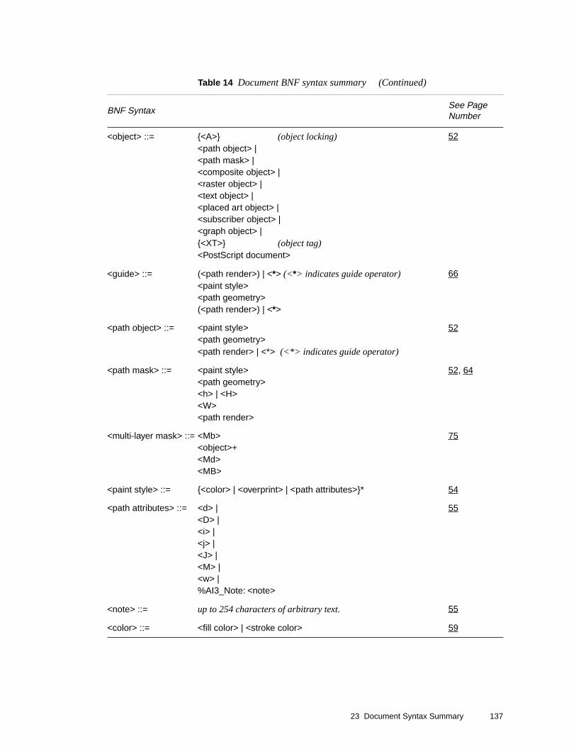
23 Document Syntax Summary 137
<object> ::= {<A>} (object locking)<path object> |<path mask> |<composite object> |<raster object> |<text object> |<placed art object> |<subscriber object> |<graph object> |{<XT>} (object tag)<PostScript document>
52
<guide> ::= (<path render>) | <*> (<*> indicates guide operator)<paint style><path geometry>(<path render>) | <*>
66
<path object> ::= <paint style><path geometry><path render> | <*> (<*> indicates guide operator)
52
<path mask> ::= <paint style><path geometry><h> | <H><W><path render>
52, 64
<multi-layer mask> ::= <Mb><object>+<Md><MB>
75
<paint style> ::= {<color> | <overprint> | <path attributes>}* 54
<path attributes> ::= <d> |<D> |<i> |<j> |<J> |<M> |<w> |%AI3_Note: <note>
55
<note> ::= up to 254 characters of arbitrary text. 55
<color> ::= <fill color> | <stroke color> 59
Table 14 Document BNF syntax summary (Continued)
BNF SyntaxSee Page Number

138 Adobe Illustrator File Format Specification 23 February 1998
<fill color> ::= <g> | (fill black ink only, or)<k> | (fill process ink, or)<x> | (fill custom ink, or)<Xa> | (fill RGB color, or)<Xx>| (fill generic custom color, or)<p> (fill pattern)
59
<stroke color> ::= <G> | (stroke black ink only, or)<K> | (stroke process ink, or)<X> | (stroke custom ink, or)<XA> | (stroke RGB color, or)<XX>| (stroke generic custom color, or)<P> (stroke pattern)
60
<ramp data> ::= [ <%_Br>+
31, 39
<color stops> ::= [ <%_Bs>+
31, 39
<overprint> ::= <O> | (fill overprint, or)<R> (stroke overprint)
62
<path geometry> ::= <m>{<path operator>}*
54
<path operator> ::= <l> | <L> | <c> | <C> | <v> | <V> | <y> | <Y> 54
<path render> ::= <N> | (closepath, no fill, no stroke; or)<n> | (neither fill nor stroke; or)<gradient instance>| (fill with gradient instance)<F> | (fill; or)<f> | (closepath, fill; or)<S> | (stroke; or)<s> | (closepath, stroke; or)<B> | (fill and stroke; or)<b> (closepath, fill and stroke)
54
<gradient instance> ::=<Bb>
<Bh> |<Bg> |{<Xm>} |<Bm> |<Bc> |<f> |<BB>
44
Table 14 Document BNF syntax summary (Continued)
BNF SyntaxSee Page Number

23 Document Syntax Summary 139
<composite object> ::=<group object> |<group with a mask> |<compound path> |<compound path mask> |<wraparound group>
52
<group object> ::= <u><object>+<U>
63
<raster object> ::= <XI> |<XG><XF>
68
<group with a mask> ::=<q>{<object>}*{<masked object>}*<Q>
63
<masked object> ::= <mask> | <object> 64
<mask> ::= <path mask> | <compound path mask> | <multi-layer mask> 64
<compound path> ::= <*u><compound path element>+<*U>
59
<compound path element> ::= <path object> | <compound group>
59
<compound group> ::=<u><compound path element>+<U>
59
<compound path mask> ::=<*u><compound path mask element>+<*U>
64
<compound path mask element> ::= <path mask> | <compound mask group>
64
<compound mask group> ::=<compound mask bottom group> |<compound mask non-bottom group>
64
Table 14 Document BNF syntax summary (Continued)
BNF SyntaxSee Page Number

140 Adobe Illustrator File Format Specification 23 February 1998
<compound mask bottom group> ::={<A>}<q><path mask>+<Q>
64
<compound mask non-bottom group> ::={<A>}<u><compound mask group>+<U>
64
<wraparound group> ::=<*w>{<object>}*{<wraparound objects>}*<*W>
93
<wraparound objects> ::=<text object> | <object>
93
<text object> ::= <To><text at a point> |<text area> |<text along a path><TO>
94
<text at a point> ::= <Tp><TP><text run>+
104
<text area> ::= <text area element>+{<overflow text>}
106
<text area element> ::=<Tp><path object><TP><text run>+
106
<text along a path> ::=<Tp><path object><TP><text run>+{<overflow text>}*
105
Table 14 Document BNF syntax summary (Continued)
BNF SyntaxSee Page Number

23 Document Syntax Summary 141
<text run> ::= {<text style> |<paint style> |<text positions> |<Tk>}*<text body>
96
<text style> ::= <Tr> | (render mode)<Tf> | (font & size)<Ts> | (rise and fall)<Tz> | (text scaling)<Tt> | (tracking)<TA> | (automatic kerning)<TC> | (intercharacter spacing)<TW> | (interword spacing)<Ti> | (indents)<Ta> | (alignment)<Tq> | (hanging quotations)<Tl> (leading)<TV> (horizontal or vertical writing)<Tv> (rotate characters 90°)<Ty> | (Kumi orientation)<TY> | (Kumi orientation, informational only)<TG> | (line break)<Tg> | (binding punctuation)<Xu> (Japanese layout rules)
97, 98, 99, 100, 102
<text position> ::= (printing only)<Tc> | (computed intercharacter spacing)<Tw> | (computed interword spacing)<Tm> | (text matrix)<Td> | (translate)<T*> | (translate down)<TR> (reset matrix; found only in pattern
prototypes)
98
<text body> ::= <Tx> | <Tj> | <T+> | <T–> 101
<overflow text> ::= {<text style> | <paint style> | <TK>}*<TX> | <T+>
96, 101
<font type> ::= AdobeType | TrueType 32
<placed art object> ::=<’><art reference><~>
107
<art reference> ::= <file reference> | <file inline> 107
Table 14 Document BNF syntax summary (Continued)
BNF SyntaxSee Page Number

142 Adobe Illustrator File Format Specification 23 February 1998
<file reference> ::= %%IncludeFile: <filename> 107
<file inline> ::= %%BeginDocument:<filename>… included file contents …%%EndDocument
107
<filename> ::= platform-specific path name of file 107
<subscriber object> ::=%AI3_Subscriber:<subscriber ID><placed art object>
107
<subscriber ID> ::= resource number of SECT resource in file 107
<graph object> ::= <Gs><graph functional spec>{<graph customizations>}<graph group object><GS>
109
<graph functional spec> ::=<graph size and dialog values>{<graph subscriptions>}<graph axis><graph axis><graph axis><graph table specs>
110
<graph size and dialog values> ::=<Gb><Gy><Gd>
110
<graph axis> ::= <Ga><GA>
110
<graph table specs> ::={<Gw>}*<Gz><Gc>+<GC>
110
<graph customizations> ::=<Gt>{<graph customization>}*<GT>
110
Table 14 Document BNF syntax summary (Continued)
BNF SyntaxSee Page Number

23 Document Syntax Summary 143
<graph customization> ::={<graph customization operator>}*<GX> | <Gg>{<Gv>}
110
<graph customization operator> ::={<Gm>}{<Gf>}{<Gy>}{<GD>}{<Ge>}{<G1>} (gee-one){<Gi>}{<Gl>} (gee-ell){<Gp>}{<Gx>}{Gr>}{<G+>}{<Gg>}{<A>}{<paint style>}*{<text style>}
110
<graph subscriptions> ::=<Gj>
110
<graph group object> ::=<u>{<graph rendered object>}*<U>
111
<graph rendered object> ::=<object> | <graph group object>{<Go>}
111
Table 14 Document BNF syntax summary (Continued)
BNF SyntaxSee Page Number

144 Adobe Illustrator File Format Specification 23 February 1998

145
Appendix A
Graph Functional Specification
The graph functional specification acts as an internal header. It contains information about the bounds of the graph, its style, its axes, and the data that make it up. From the functional spec, Adobe Illustrator can reconstruct the graph (Adobe Illustrator does not automatically recalculate the graph on reading in a file); in fact, Adobe Illustrator can reconstruct a graph from no more than the functional spec and does not require graph objects at all.
Statements in the functional spec take the form of comments, and begin with the characters %_. This allows an Adobe Illustrator file with a graph in it to be used as an EPS file, in which comments are not executed. The following example shows a simple functional spec.
%_Gs
%_548 122 301 440 Gb
%_5 0 0 14 1 1 0 0 3 44 Gy
%_7 2 1 0 90 80 0 Gd
%_1 () Ga 0 14 0 1 0.2 0 1 () GA
%_2 () Ga 0 14 0 5 1 0 0 () GA
%_4 () Ga 0 14 0 5 1 0 0 () GA
%_4 4 1 1 Gz
%_() Gc (FIRSTCOL) Gc (SECONDCOL) Gc (THIRDCOL) Gc (GLOVES) Gc 1
3 1 (BALLS) Gc 2 2 5 (BATS) Gc 3 4 2 Gc GC
The %_Gs operator opens the graph section. The next operator, Gb, defines the bounds of the graph and determines where Adobe Illustrator draws the graph’s axes. Gy and Gd apply some of the values from Illustrator’s Graph Style dialog box. The three GA operators control how values appear on the axes. The Gz operator works with the GA operator to specify the graph axis.
The Gc operator reads in cell values, one by one, and puts them in the cell data table—rows and columns like a spreadsheet—from which Adobe Illustrator constructs its graphs. Operators in Adobe Illustrator are limited to one string parameter and a maximum of 16 parameters overall; consequently, there is usually more than one Gc operator to a line. The cells in the series read from left to right in a row; then the next row down is read in. String

146 Adobe Illustrator File Format Specification 23 February 1998
values appear within parentheses. If a cell holds no value, the file holds its place with a pair of empty parentheses. In the example
%_() Gc (FIRSTCOL) Gc (SECONDCOL) Gc (THIRDCOL) Gc (GLOVES) Gc 1
3 1 (BALLS) Gc 2 2 5 (BATS) Gc 3 4 2 Gc GC
the contents of row1 column1 is an empty string. Because it must be allowed to hold a string, the Gc operator follows it (one string allowed per operator). The contents of row1 column2 is the string FIRSTCOL. Again, because it is a string, the Gc operator must immediately follow it. The Gc parameter doesn’t “care” about the coordinates of the parameters it sets, only their number. For example, if there were 40 numerical data points to place in the table, the first Gc can place 16, the second Gc can place 16, and the third Gc can place eight—with no regard to where those 40 data points fall on the table. It is the order in which they occur within the file that determines their row and column coordinates.
If you are preparing a file to be used with Adobe Illustrator, label and data point order is critical to creating an accurate graph.
The final GC ends the data table.
Note Adobe Illustrator notes any edits you make to the graph after you build it initially; it specifies those edits as a series of changes following the functional spec. These customizations are covered in section A.3, “Graph Customizations.”
A.1 Operators in the Functional Spec
Gs This operator signals the beginning the graph object. Must be the first operator in this graph object. It takes no parameters.
GS This operator signals the end the graph object. It takes no parameters.
left top right bottom Gb The Gb operator shows the bounds of the graph. The parameters are decimal numbers, in the same coordinate system as other objects. This rectangular area defines where Adobe Illustrator draws the axes’ lines. The axis labels, category labels, legend boxes, and legend labels are all slightly outside this rectangle. The axis lines are drawn exactly on the edges of this rectangle. This is a pre-customization rectangle. See page 154 for more information.
graphType shadow dataPaintOrder pieLegendStyle drawMarks drawLines drawLinesAsShapes drawLegendsAcrossTop lineShapeWidth whichAxis [piePercentage piePctDigits] Gy
This operator defines values for the Graph Style dialog box, just as does Gd; however, these values can be applied to individual series in a graph, overriding, for that series, the default graph style.

147
graphType This is the style of graph, for the whole graph (which may be overridden in any number of series), or for one series. The values for graphType are:
5—grouped column graph6—stacked column graph7—line graph8—pie chart9—scatter graph10—area graph
Note The values for scatter and area are in the opposite order from the dialog box and tools.
shadow This controls whether to create an object showing a shadow when creating the graphical objects. 1 means draw the shadow. Values: 0 or 1. Default: 0.
dataPointOrder When individual items in a data series overlap graphically, the items corresponding to the upper rows in the cell table are covered by the graphical objects corresponding to the lower rows in the cell table. A value of 1 does the opposite. See the seriesPaintOrder parameter in the Gd operator for more information.
pieLegendStyle Legends in pie charts can be numerous types; they can be the same as for bar and line graphs (boxes along the right or top edge, with labels next to them), a label within each wedge, or none at all. The values are:
14 same as bar/line graphs15 legends in wedges16 no legends
drawMarks When creating line and scatter graphs, Adobe Illustrator can place small marks at the data points or have lines go through them without special marks. This parameter controls the existence of the marks. 1 means draw marks. Values: 1 or 0. Default: 0.
drawLines When creating line and scatter graphs, Adobe Illustrator can draw lines that connect the data points, or not. This parameter controls the existence of the lines. 1 means draw them. Note that if this and the above value are both zero, Adobe Illustrator draws nothing within the data area. Values: 1 or 0. Default 1.
drawLinesAsShapes When creating line and scatter graphs, Adobe Illustrator can use simple lines to represent the data, or use shapes that represent thick lines. 1 means draw the shapes. Values: 1 or 0. Default: 0.
Note that if drawLines is 0, this parameter is ignored (but still must be supplied).
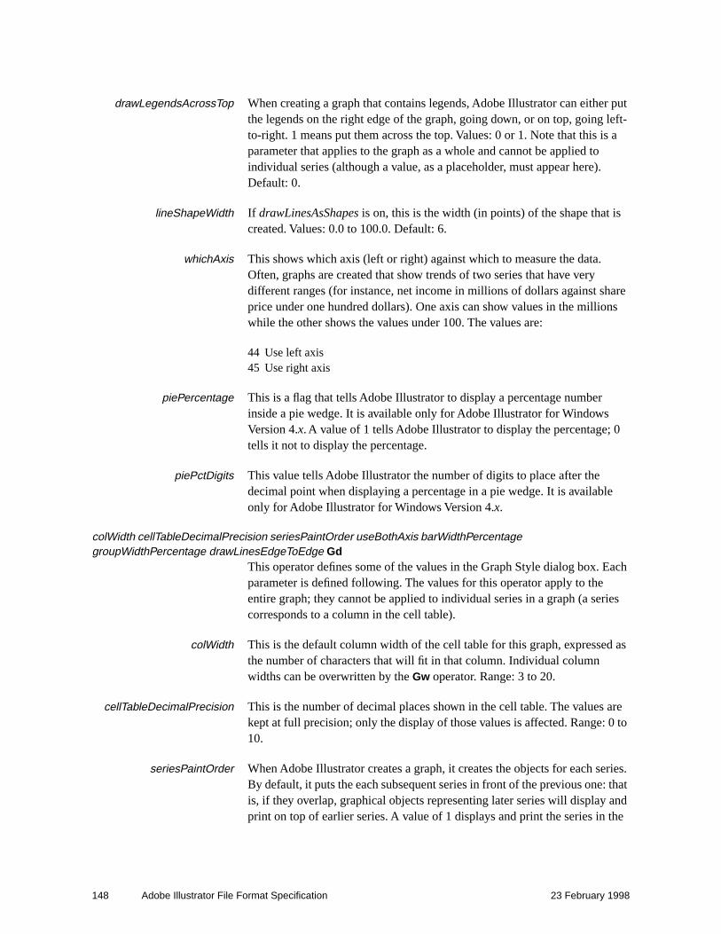
148 Adobe Illustrator File Format Specification 23 February 1998
drawLegendsAcrossTop When creating a graph that contains legends, Adobe Illustrator can either put the legends on the right edge of the graph, going down, or on top, going left-to-right. 1 means put them across the top. Values: 0 or 1. Note that this is a parameter that applies to the graph as a whole and cannot be applied to individual series (although a value, as a placeholder, must appear here). Default: 0.
lineShapeWidth If drawLinesAsShapes is on, this is the width (in points) of the shape that is created. Values: 0.0 to 100.0. Default: 6.
whichAxis This shows which axis (left or right) against which to measure the data. Often, graphs are created that show trends of two series that have very different ranges (for instance, net income in millions of dollars against share price under one hundred dollars). One axis can show values in the millions while the other shows the values under 100. The values are:
44 Use left axis45 Use right axis
piePercentage This is a flag that tells Adobe Illustrator to display a percentage number inside a pie wedge. It is available only for Adobe Illustrator for Windows Version 4.x. A value of 1 tells Adobe Illustrator to display the percentage; 0 tells it not to display the percentage.
piePctDigits This value tells Adobe Illustrator the number of digits to place after the decimal point when displaying a percentage in a pie wedge. It is available only for Adobe Illustrator for Windows Version 4.x.
colWidth cellTableDecimalPrecision seriesPaintOrder useBothAxis barWidthPercentage groupWidthPercentage drawLinesEdgeToEdge Gd
This operator defines some of the values in the Graph Style dialog box. Each parameter is defined following. The values for this operator apply to the entire graph; they cannot be applied to individual series in a graph (a series corresponds to a column in the cell table).
colWidth This is the default column width of the cell table for this graph, expressed as the number of characters that will fit in that column. Individual column widths can be overwritten by the Gw operator. Range: 3 to 20.
cellTableDecimalPrecision This is the number of decimal places shown in the cell table. The values are kept at full precision; only the display of those values is affected. Range: 0 to 10.
seriesPaintOrder When Adobe Illustrator creates a graph, it creates the objects for each series. By default, it puts the each subsequent series in front of the previous one: that is, if they overlap, graphical objects representing later series will display and print on top of earlier series. A value of 1 displays and print the series in the

149
opposite order; that is, the first series will be frontmost in the graph and will paint over other series if they overlap. Note that this does not change the position of the series; only the painting order. Values: 0 or 1; default value 0.
useBothAxis The user can choose either left, right, or both axes to display, and independently set the axis numbers and tick placement for each axis. A parameter value of 1 “copies” the values from one axis to the other. Which axis is copied depends on which axis has been chosen as the default for all series (both may have been chosen, in which case Adobe Illustrator ignores this parameter). If one axis has been chosen, the other axis is copied. Values: 0 or 1. Default: 0.
barWidthPercentage This is the percentage of the width available for a bar that will be used for that bar. (In the Adobe Illustrator manual, vertical-bar graphs are called “column graphs.” Use of the term “bar” distinguishes the graphic rectangle that represents one piece of data in the cell table from a column of cells in the table). Adobe Illustrator divides the available width of a graph into portions depending on how many series there are and how many individual bars there are per series. For example, if this parameter value is 100, for grouped-column graphs there would be no space at all between individual bars in a group. The lower the percentage, the more space between individual bars. The higher, the less—values over 100, which are legal, causes bars to overlap. See the dataPaintOrder parameter of Gy for how to influence the paint order of individual overlapping bars. For stacked-column graphs, individual bars are all in the same stack—the barWidthPercentage and groupWidthPercentage are multiplied to obtain the real percentage to use for each stack. If both are 100, no space shows between stacks. One value of 64 and the other of 100, versus both values of 80, shows the same graph for stacked-column graphs but shows different group and bar spacing for grouped-column graphs. Range: 1.0 to 1000.0 (that is, one-hundredth of the available width to ten times the available width).
groupWidthPercentage This is the percentage of the width available for a group (in grouped-column graphs) or a single stack (in stacked-column graphs) that will be used for that group or stack. See barWidthPercentage, above, for a fuller description. Range: 1.0 to 1000.0 (that is, one-hundredth of the available width to ten times the available width).
drawLinesEdgeToEdge In line graphs, the user can decide whether to leave a little space between the left and right axes and the beginning and end of the data lines. Usually this is done to leave room for labels at the bottom of the graphs. This parameter defines whether or not to draw the lines right to the edges. Note that this widens the area available for each label along the bottom, because the same number of labels now have a slightly wider area to draw. 1 means draw all the way to the edge. Values: 0 or 1. Default: 0.

150 Adobe Illustrator File Format Specification 23 February 1998
leftColumn topRow rightColumn rightRow sectionID GjThis operator concerns the Macintosh publish and subscribe facility available in System 7. It reads in an edition which has been published as text. The bounds (0 is the first column) show how big the section is, although that is ignored: if the read-in section is larger or smaller than the bounds, they’re re-set by Adobe Illustrator. The sectionID shows the resource ID of the section (in a sect resource), as stored in the file. See Inside Macintosh Volume VI for more information on publish and subscribe. If you need to use this, you will need to store the sectionHandle in the sect resource with the given ID, the bounds in a bnds resource of the given ID (whose format is a rectangle of Fixed values: left, top, right, bottom), and the section options in a psop resource of the given id (whose format is a two-byte integer, value 0).
whichAxis beforeString Ga This is the beginning of the specification of a graph axis. It continues and ends with the GA operator.
whichAxis This tells which axis to set to this specification. The values are:
1 Bottom axis2 Left axis4 Right axis
beforeString This string is appended to the label next to each axis tick mark; a value of (units) shows as “100 units” rather than as just 100. These labels show the numerical representation of the tick, which can include a currency symbol or some other representation before the value. If the value of beforeString is $, the axis label becomes $100 instead of 100. Length: up to 9 characters. Note that any characters other than standard ASCII must be entered as an octal number with a slash (this is a PostScript standard), so £ and ¥ must be decoded into their ASCII values.

151
useManualValues tickMarkType minimumValue maximumValue betweenValue smallTicksPerValue drawMarksBetweenLabels afterString GA
useManualValues The user can choose to have Adobe Illustrator decide which axis values are appropriate given the range of the cell data, or the user can specify his own values (for the current axis, specified by the Ga operator). 1 means use manual values. Values: 0 or 1. Default: 0.
tickMarkType The user can specify short tick marks, tick marks that stretch to the other edge of the graph, or none. The values are:
13—no tick marks14—short tick marks15—long tick marks
minimumValue If the user has specified manual values for the axis, this parameter supplies the lower of the two values. Depending on the betweenValue, minimumValue may correspond to the topmost or bottommost tick mark. Range: any decimal number.
maximumValue If the user has specified manual values for the axis, this parameter supplies the higher of the two values. Depending on the betweenValue, maximumValue may correspond to the topmost or bottommost tick mark. Range: any decimal number.
betweenValue If the user has specified manual values for the axis, this parameter supplies the numerical difference between subsequent tick marks. If this number is positive, then minimumValue shows up on the bottom of the y-axis (on the left in the case of the x-axis). If this number is negative, then maximumValue shows up on the bottom of the y-axis (on the left in the case of the x-axis). Range: any decimal number.
smallTicksPerValue The user may want a graph with tick marks every 10, but labels every 20. Adobe Illustrator uses smallTicksPerValue to divide betweenValue into smaller segments and display extra tick marks without displaying labels.

152 Adobe Illustrator File Format Specification 23 February 1998
Adobe Illustrator divides the betweenValue by this number, and zero is a valid result meaning none. This means that 0 and 1 do the same thing: produce no small ticks. Range: integers between 0 and 1000. Default: 0.
drawMarksBetweenLabels This applies only to the category axis. Sometimes the user wants tick marks on the category axis to line up exactly with the labels (usually in the case of line and area graphs), and sometimes the user wants ticks between the labels (usually in the case of stacked-column and grouped-column graphs). If 1, the category axis draws tick marks between the labels. Values: 0 or 1. Default: 0.
afterString As with beforeString in the Ga operator, this string is appended to the label next to each axis tick mark; a value of (units) shows as “100 units” rather than as just 100. Length: up to 9 characters. See beforeString for character value limitations.
rows columns firstDataRow firstDataColumn GzThis shows the size of the cellTable in rows and columns (1 means 1 row or column). It also shows the row index and column index of the first row/column containing data (0 means first row). Only 1 row/column of labels is allowed, so firstDataRow and firstDataColumn can be only 0 or 1. The other parameters can be anything from 1 to whatever will fit in memory. There must be at least one row and one column in the table. This operator must be followed by however many Gc operators it takes to fill the table with data.
cellValue1 cellValue2 cellValue3 … cellValueX GcThis operator reads in cell values, one by one, and puts them in the table. Every cell in the table must be enumerated, even if it’s empty. Use as many invocations of Gc as necessary until the table is full or until all subsequent cells are empty. The first cell value goes to the top-left cell, subsequent cells along the top row are filled until the number of columns (as specified in the Gz operator) has been reached. Then the next row is filled from left to right.
The number of parameters to Gc doesn’t necessarily match the number of columns in the table; it is constrained by the following rules: only one parameter can be a string and there cannot be more than 15 parameters. This means that if the top row contains any labels, there will probably be many Gc invocations, each with one parameter; then for the data rows there will be fewer invocations, each with a greater number of parameters. String parameters can be any length up to 255 characters (the maximum line length for Adobe Illustrator is 128 characters), and numerical values can be anything. Empty cells are denoted by a set of empty parentheses.
For example, the following table and Gc operator and its operands are equivalent:

153
FIRSTCOL SECONDCOL THIRDCOLGLOVES 1 3 1BALLS 2 2 5BATS 3 4 2
%_() Gc (FIRSTCOL) Gc (SECONDCOL) Gc (THIRDCOL) Gc (GLOVES) Gc 1
3 1 (BALLS) Gc 2 2 5 (BATS) Gc 3 4 2 Gc GC
col width1 width2 width3 … widthX numParams GwThis overrides the default column width (expressed as a number of characters that fit in the table) given in the Gy operator. The first parameter is the column for which to start setting widths (0 is the first column); the next parameters (there must be at least one, and can be up to 14) set the width of that column and the next n (<14). To set the width for more than 14 columns, use multiple invocations of Gw. If –1 is the column width, it is considered a placeholder default column width. The operand numParams is the number of parameters to the operator, including the col parameter.
GC The cell table is finished. This is an indication to Adobe Illustrator that the temporary state and data structures it has set up to read in the cell table can be disposed.
A.2 End of the Functional Specification
This ends the functional specification of the graph. All the operators shown so far should be written out with every line beginning with the PostScript comment characters %_ (<percent> <underbar>).
A.3 Graph Customizations
After Adobe Illustrator has created the functional specification (and before it writes any of the graph objects), it tracks any edits that the user may have made to the graph in the form of changes to that functional spec. Such changes are called customizations.
Much like Paint Style parameters, Adobe Illustrator maintains a “running” customization—only the changes to the customization appear in the file. The Gt and GT operators bracket the customizations.
Adobe Illustrator writes out the GX operator to add the customization to the list for the graph.
If a GX operator appears before another operator with that parameter has appeared—anywhere within the entire set of customizations—Adobe Illustrator assumes that the parameter holds the initial value. For some parameters, the initial value is not one of the legal values. This means that the operator which contains this parameter must always appear somewhere in the

154 Adobe Illustrator File Format Specification 23 February 1998
list of customizations before the GX for a customization for which this parameter is necessary.
For example, if Gx appears in a customization that has been defined to apply to a column, but the Gr operator has not appeared, it is assumed that the target column is 0 (zero) since that is the initial value. That is, there is an implicit 0 Gl (zero gee-ell) at the beginning of the list of customizations. This applies to all operators. Note that some, like Gi, have a default value that is illegal. This means that before the GX operator appears on a customization that applies to an axis, there must be a Gi operator.
As another example, the bar design type parameter’s initial value is 0, but that’s not one of the legal values. Thus, before the GX appears for a bar-design customization, the operator containing the bar design type—GD—must appear). For each graph in a file, the value is reset to its initial state; that is, the “running” customization is not carried from graph to graph.
Note that some operators take parameters that do not have a meaning in the particular context; in this case, the parameters are used to set structure fields in the customizations, but they are ignored.
Some fields necessarily do not take a value; there is a special construct for this: –– (two adjacent hyphens). This construct is used when a customization sets, for instance, the paint style of a group but the user did not fill in the color of the group. In the case where the group contains objects of various strokes—and the user changes the Paint Style without wanting to change the objects’ strokes—Adobe Illustrator must create a Paint Style that does not change the stroke style but does change whatever the user wants changed.The –– parameter and the w operator are used as part of the construction of a “Set Paint Style” customization, to make sure that this customization will not reset the stroke width of a target that has previously had its width set by another “Set Paint Style” customization.
A.3.1 Customization Operators
version Gt This marks the beginning of users’ customizations to the graph.The current version is 2.
GT This marks the end of the list of customizations.

155
target graphCustomization Gx This sets up the main part of the customization, itemizing the target of the customization and the basic customization type. The parameters are:
target is an index into all possible pieces of a graph. This is the object to which the customization is applied. For each type of target, other parameters to other operators will have to be filled in. For instance, if the target is one entire axis (9), the Gi operator should precede the GX operator, denoting which axis is the target. Initial value: 0. Possible targets are:
0 entire graph1 all series, including legends2 one series, including legends3 one series but not its legend4 one data bar/line/wedge5 all data marks6 one series’ and its legend’s marks7 one series’ marks, but not legend’s8 one data line segment’s mark9 one axis, including text, ticks, line10 category axis’ main line11 one axis’ set of major tick marks12 one axis’ single major tick mark13 one axis’ set of tick labels14 one axis’ single tick label15 all legends’ text16 one legend’s text17 one numerical axis’ main line18 one legend’s box or line, not mark19 one legend’s mark20 all labels along category axis21 one label of category axis22 entire “shadow” object23 every tick of one axis24 all minor (small) ticks of one axis25 one minor (small) tick of one axis
graphCustomization This parameter enumerates the type of customization. If this is an Adobe Illustrator Customization, it indicates the illustratorCustomization (see the Gp operator). Initial value: 0. The values are:
0 Illustrator Customization1 Set Series’ Graph Style2 Set Column (Bar) Design3 Set Mark Design

156 Adobe Illustrator File Format Specification 23 February 1998
illustratorCustomization Gp For customizations that involve general illustrator operators (see list just below), this operator enumerates the type of customization. This is ignored if the graphCustomization parameter to the Gx operator indicates that this customization is a graph-specific customization. Initial value: 0. Values (for illustratorCustomization) are:
0 Move/Shear/Rotate/Scale1 Set Paint Style9 Send To Front/Back10 Set Character Style11 Set Layout Style
changeMethod G+ Customizations usually reset properties of objects regardless of the previous value of the property. A few, however, involve adding or subtracting something from the previous property. There is an Adobe Illustrator operator to add two points to the type size; to mimic this customization, the G+ operator indicates that the customization’s values are to be added to the current values, rather than replacing the values. Initial value: 0. Values (for changeMethod) are:
0 Reset to new value1 Add new value to previous value
Note Adding or subtracting values doesn’t apply to the values in the customization itself. It affects how those values will apply to objects when Adobe Illustrator recalculates the graph.
sendToFront G1 (gee-one) For the Send-to-Front and Send-to-Back customizations, the parameter denotes front or back (since the illustratorCustomization parameter of the Gp operator is the same for both operators). Initial value: 0. Values are:
0 Send to back1 Send to front
doFill doStroke fillColorStyle strokeColorStyle isAMask GfFor the Set Paint Style customization, these parameter denote the settings of the fill and stroke radio buttons that are not covered by the standard Paint Style operators. For those path objects not in graphs, the operator that finishes the path object denotes the values. Since this operator does not create a path object, but merely denotes its properties, there needs to be operators specifically for these values. The parameters are:
doFill Used to denote that a non-empty fill style has been selected. 1 means that the customization creates a fill (of style fillStyle, below). Initial value: 0. Values: 0 or 1.

157
doStroke Same as doFill, except it applies to the stroking. Initial value: 0.
fillStyle Denotes the style of filling for this customization. Initial value: 0. The values are:
0 black (or white)1 process2 pattern3 custom color4 blend (applies only to Adobe Illustrator for Windows Version 4.0)
strokeStyle Denotes the style of stroking for this customization. The values are the same as for fillStyle. Initial value: 0.
isAMask This object has had the Mask box checked in the Paint Style dialog. 1 means the object is a mask. Initial value: 0. Values: 0 or 1.
column Gl (gee-ell) For targets that are a series or a data point within a series, this is the column index in the table that corresponds to the series. Note that 0 (zero) means the first column that contains graphable numeric data; that is, if the first column consists of labels, then the second column is considered zero. Initial value: 0.
row Gr For targets that are a series or a data point within a series, this is the row index in the table that corresponds to the index within the series indicated by the Gl (gee-ell) operator. Note that 0 (zero) means the first row that contains graphable numeric data; that is, if the first row is labels, then the second row is considered zero. Initial value: 0.
whichAxis Gi For a customization that applies to an object inside an axis, this operator tells Adobe Illustrator which axis the object is inside.
whichAxis For targets that are part of an axis, this parameter denotes the axis (left, right, bottom or top). Initial value: 0.
The values are:
1 Bottom axis2 Left axis4 Right axis8 Top axis (Adobe Illustrator Japanese Edition only)
a b c d h v generalGraphType reserved1 reserved2 GmFor customizations that use matrices (the graphCustomization parameter in the Gx operator is Adobe Illustrator Customization, and the illustratorCustomization parameter in the Gp operator is Move/Shear/Rotate/Scale). The parameters are:

158 Adobe Illustrator File Format Specification 23 February 1998
a, b, c, d, h, v These are the values for the matrix. They (the h and v) are in artwork-coordinates, and all are decimal values. Initial values: 0, 0, 0, 0, 0, 0.
generalGraphType Some customizations only look good for certain general types of graphs; that is, shearing of the bars in stacked-column graphs would not look good if applied to the data in pie charts, yet when applied to grouped-column graphs it achieves a good effect. This denotes the general type of graph to which the customization should be applied. This parameter will have meaning in the case where the user reads this file into Adobe Illustrator, then changes the graph type. Initial value: 0. The values are:
1 Grouped- and Stacked-column2 Scatter and line graphs3 Pie charts4 Area graphs5 All graphs
reserved1 Set to 0.
reserved2 Set to 0.
designName designType repeatPartialType rotateLegend GDThis operator sets up the parameters for bar design customizations (see the Gp operator).
designName This is the name of the design. The design was set up, just like a pattern, in the prolog. Initial value: zero-length string.
designType This denotes the type of the design. Initial value: 0. The values are:
6 Vertically-scaled design7 Uniformly-scaled design8 Repeating design9 Sliding design
repeatPartialType For repeating bar design customizations, this denotes whether to chop the design representing any partial values, or to scale it. Initial value: 0. The values are:
16 Chop partial values17 Scale partial values
rotateLegend When using bar designs, the user can have Adobe Illustrator automatically rotate the design in the legend box. This denotes whether to do it. 1 means rotate the design in the legend box. Initial value: 0. Values: 0 or 1.

159
repeatEachValue Ge For customizations that set the bar design (see Gp operator), and for which the design type is a repeat design (see GD operator), this operator denotes the value for each repetition of the design. Initial value: 0.0. Values: any decimal number but zero.
tickValue Gv For targets that are either one tick mark or one tick label, this is the numeric value corresponding to that tick mark. That is, if the user changes to red the tick line next to the 100 on the tick axis, this number tells Adobe Illustrator that any tick line on that axis that corresponds to the value 100 (no matter how many tick lines there are or what their values), is to be red. Initial value: 0.0. Values: any decimal number.
Note This is the only customization operator that appears after the Gx operator within one customization.
GX This finalizes the customization, which has been described by any of the previous values.
target column row whichAxis illustratorCustomization graphCustomization ignored changeMethod Gg
Note This operator is not written by Adobe Illustrator; all the parameters are redundant with parameters of other, more efficient, operators. While Adobe Illustrator does currently read this in, and some files written by beta versions of Adobe Illustrator 3.x may have this operator in it, it is highly recommended that the other operators be used instead. Future versions may not read this operator.
This sets up the main part of the customization, itemizing the target of the customization and the basic customization type. The parameters are:
target See Gx operator.column See Gl operator.row See Gr operator.whichAxis See Gi operator.illustratorCustomization See Gp operator.graphCustomization See Gx operator.ignored Unused. Set to 0 (zero).changeMethod See G+ operator.

160 Adobe Illustrator File Format Specification 23 February 1998

161
Appendix B
Changes Since Earlier Versions
Changes since June 1997version
• Included features from Adobe Illustrator version7.
Changes since October 1992 version
• Included features from Adobe Illustrator versions 5 and 6.
• Substantial document reorganization.
Changes since May 4, 1991 version
• Updated entire document to include information on the Adobe Illustrator 3.x and 4.x file formats—DRAFT specification only.
• Reformatted in the new document format.
Changes since July 18, 1990 version
• The description for the operator q was changed from “except that the first object in the group specifies” to “except that some objects in the group specify.”
• The cover addresses were updated.
Changes since December 29, 1989 version
• The descriptions for the operators o and a in section 5.7 have been corrected. (They were reversed.)

162 Adobe Illustrator File Format Specification 23 February 1998

163
Index
Symbols
%_Br operator 42%_Bs operator 41& operator 35' operator 107* operator 66@ operator 35_ (underbar) operator 35~ operator 108
A
A operator 54AI3_BeginEncoding comment 32AI3_ColorUsage comment 22AI3_DocumentPreview comment 21AI3_PaperRect comment 22AI3_TemplateBox comment 21AI3_TemplateFile comment 21AI3_TileBox comment 21AI5_ArtFlags comment 19AI5_ArtSize comment 18AI5_Begin_NonPrinting comment
84AI5_BeginGradient comment 40AI5_BeginLayer comment 71AI5_BeginPalette comment 78AI5_End_NonPrinting comment 84AI5_EndLayer comment 71AI5_EndPalette comment 78AI5_FileFormat comment 18AI5_NumLayers comment 20AI5_OpenToView comment 20AI5_OpenViewLayers comment 20AI5_TargetResolution comment 20AI6_ColorSeparationSet comment
23AI7_ImageSettings comment 22
alignment 101art, placed 107artboard 30attribute, of object 81
B
B operator 58b operator 58Backus-Naur form 11BB operator 45Bb operator 45Bc operator 49BD operator 44Bd operator 40, 41BeginProlog comment 14Bg operator 45Bh operator 48bitmapped image 68blends 38Bm operator 49Bn operator 40BNF 11bounding box 16, 21BoundingBox comment 16
C
C operator 57c operator 57character attribute 93CMYKCustomColor comment 17color 59
operators 60color palette 78color separation sets 23comments 9
pseudo 10structural 10

164 Index 23 February 1998
containers 63CreationDate comment 16Creator comment 15custom colors 16Custom comment 29
D
D operator 55d operator 55dash pattern 55document files 17document fonts 17document structure 8Document Structuring Conventions 8document types 116DocumentCustomColors comment
16DocumentFiles comment 17DocumentFonts comment 17DocumentNeededFonts comment 17DocumentNeededResources
comment 18DocumentProcessColors comment
16document-supplied resources 18DocumentSuppliedFonts comment
17DocumentSuppliedResources
comment 18
E
E operator 35EndComments comment 14EndProlog comment 14EPS format 13EPSF 14
F
F operator 58f operator 58filling rules 58final form 13flatness 55font encoding 32fonts 32For comment 16
G
G operator 60g operator 60G+ operator 156G1 operator 156GA operator 151Ga operator 150Gb operator 146GC operator 153Gc operator 152GD operator 158Gd operator 148Ge operator 159Gi operator 157Gj operator 150Gl operator 157global objects 51Gm operator 157Go operator 112Gp operator 156Gr operator 157gradient instance 44gradient palette 38gradients 38
imaging 49graphs 109
customizations 153grid 118groups 63GS operator 112, 146Gs operator 146GT operator 154Gt operator 154guides 66Gv operator 159Gw operator 153GX operator 159Gx operator 155Gy operator 146Gz operator 152
H
H operator 64h operator 64Halftone comment 27header 14high-resolution 16HiResBoundingBox comment 16hyphen 100
hyphenation dictionaries 83
I
i operator 55image, bitmapped 68implementation 121implementation issues 121IncludeFont comment 32IncludeResource comment 21
J
J operator 56j operator 55justification 101
K
K operator 60k operator 60Kanji fonts 103kerning 96
L
L operator 57l operator 57layer 71
pattern 35leading 99line cap 56line join 55line width 56lineto operator 37locked objects 54
M
M operator 56m operator 56Macintosh computer 115mask
clipping 63multi-layer 75text as 65
miter limit 56moveto operator 36, 56
N
N operator 58

Index 165
n operator 58name collisions 51NeXT 118nonprinting elements 84
O
O operator 63object
attribute 81raster 68
Options comment 24overprint 62
P
P operator 62p operator 62PAGE resource 116PageSize comment 29paint style 54palette cell 78path 54
compound 59construction operators 56filling rules 58painting operators 58resolution 81
pattern 34pattern definition 36pattern layer 35placed art 107PPD comment 25PREC resource 116preview image 21
PICT 115procedure sets 8process colors 16Process comment 28procsets 18prolog 8, 14
header 14pseudo comments 10
Q
Q operator 64q operator 64
R
R operator 63
radial gradients 47raster object 68resolution 81resource
initialization 32revisable form 13RGBCustomColor comment 21ruler origin 30
S
S operator 58s operator 58save options 116script 8
body 52setup 31
script trailer 114separations, color 23setcmykcolor operator 60setdash operato 55setlinecap operator 56setlinejoin operato 55setlinewidth operator 56setmiterlimit operator 56setrgbcolor operator 60setup 8StringAdd comment 26StringSplit comment 26structural comments 10subscript 100superscript 100
T
T- operator 101T– operator 91, 101T* operator 88T+ operator 91, 100, 101TA operator 90, 97Ta operator 89, 102TC operator 89, 99Tc operator 89, 99Td operator 88TE operator 32TEMP resource 115template 21template file 115
text 85alignment 101area 85, 106attributes 93final-form 85justification 101kerning 96leading 99object 93on a path 85, 104operators summary 87point 85rendering 95revisable 85spacing 97subscript 100superscript 100wraparound 93
text container 94text path 94Tf operator 32, 89TG operator 92Tg operator 91Ti operator 90, 102Title comment 16Tj operator 90, 96TK operator 90, 97Tk operator 90, 97Tl operator 89, 100Tm operator 88TO operator 88, 94To operator 87, 94TP operator 88, 95Tp operator 88, 95Tq operator 90TR operator 88Tr operator 88trailer 8Ts operator 89, 100Tt operator 89, 97Tu operator
See Xu operatorTV operator 91Tv operator 91TW operator 89, 99Tw operator 89, 99TX operator 90Tx operator 90TY operator 92Ty operator 92TZ operator 32, 33

166 Index 23 February 1998
Tz operator 103
U
U operator 63u operator 63
V
V operator 57v operator 57
W
W operator 65w operator 56winding orde 55Windows 120
X
X operator 61x operator 60XF operator 69XG operator 69Xm operator 47XT operator 67Xu operator 92
Y
Y operator 57y operator 57