Agreement - UNECE Homepage€¦ · 3 Regulation No. 112 Uniform provisions concerning the approval...
72
GE.10- Agreement Concerning the Adoption of Uniform Technical Prescriptions for Wheeled Vehicles, Equipment and Parts which can be Fitted and/or be Used on Wheeled Vehicles and the Conditions for Reciprocal Recognition of Approvals Granted on the Basis of these Prescriptions * (Revision 2, including the amendments which entered into force on 16 October 1995) _________ Addendum 111: Regulation No. 112 Revision 2 Incorporating all valid text up to: Supplement 6 to the original version of the Regulation - Date of entry into force: 10 October 2006 Supplement 7 to the original version of the Regulation - Date of entry into force: 2 February 2007 Supplement 8 to the original version of the Regulation - Date of entry into force: 11 July 2008 Corrigendum 1 to Supplement 8, subject of Depositary Notification C.N.258.2008.TREATIES-1 dated 9 April 2008 Supplement 9 to the original version of the Regulation - Date of entry into force: 15 October 2008 Corrigendum 1 to Supplement 5, subject of Depositary Notification C.N.257.2008.TREATIES-1 dated 9 April 2008 Supplement 10 to the original version of the Regulation - Date of entry into force: 22 July 2009 Corrigendum 2 to Supplement 8, subject of Depositary Notification C.N.258.2009.TREATIES-3 dated 30 April 2009 Supplement 11 to the original version of the Regulation - Date of entry into force: 24 October 2010 Corrigendum 3 to Supplement 8, subject of Depositary Notification C.N.293.2010.TREATIES-2 dated 16 June 2010 Supplement 12 to the original version of the Regulation - Date of entry into force: 19 August 2010 Uniform provisions concerning the approval of motor vehicle headlamps emitting an asymmetrical passing beam or a driving beam or both and equipped with filament lamps and/or light-emitting diode (LED) modules _________ UNITED NATIONS * Former title of the Agreement: Agreement Concerning the Adoption of Uniform Conditions of Approval and Reciprocal Recognition of Approval for Motor Vehicle Equipment and Parts, done at Geneva on 20 March 1958. E/ECE/324/Rev.2/Add.111/Rev.2-E/ECE/TRANS/505/Rev.2/Add.111/Rev.2 20 September 2010
Transcript of Agreement - UNECE Homepage€¦ · 3 Regulation No. 112 Uniform provisions concerning the approval...
GE.10-
Agreement Concerning the Adoption of Uniform Technical Prescriptions for
Wheeled Vehicles, Equipment and Parts which can be Fitted and/or be Used on Wheeled Vehicles and the Conditions for Reciprocal Recognition of Approvals Granted on the Basis of these Prescriptions*
(Revision 2, including the amendments which entered into force on 16 October 1995) _________
Addendum 111: Regulation No. 112 Revision 2
Incorporating all valid text up to: Supplement 6 to the original version of the Regulation - Date of entry into force: 10 October 2006 Supplement 7 to the original version of the Regulation - Date of entry into force: 2 February 2007 Supplement 8 to the original version of the Regulation - Date of entry into force: 11 July 2008 Corrigendum 1 to Supplement 8, subject of Depositary Notification C.N.258.2008.TREATIES-1 dated 9 April 2008 Supplement 9 to the original version of the Regulation - Date of entry into force: 15 October 2008 Corrigendum 1 to Supplement 5, subject of Depositary Notification C.N.257.2008.TREATIES-1 dated 9 April 2008 Supplement 10 to the original version of the Regulation - Date of entry into force: 22 July 2009 Corrigendum 2 to Supplement 8, subject of Depositary Notification C.N.258.2009.TREATIES-3 dated 30 April 2009 Supplement 11 to the original version of the Regulation - Date of entry into force: 24 October 2010 Corrigendum 3 to Supplement 8, subject of Depositary Notification C.N.293.2010.TREATIES-2 dated 16 June 2010 Supplement 12 to the original version of the Regulation - Date of entry into force: 19 August 2010
Uniform provisions concerning the approval of motor vehicle headlamps emitting an asymmetrical passing beam or a driving beam or both and equipped with filament lamps and/or light-emitting diode (LED) modules
_________
UNITED NATIONS
* Former title of the Agreement: Agreement Concerning the Adoption of Uniform Conditions of Approval and Reciprocal Recognition of Approval for Motor Vehicle Equipment and Parts, done at Geneva on 20 March 1958.
E/ECE/324/Rev.2/Add.111/Rev.2−E/ECE/TRANS/505/Rev.2/Add.111/Rev.2
20 September 2010

3
Regulation No. 112
Uniform provisions concerning the approval of motor vehicle headlamps emitting an asymmetrical passing beam or a driving beam or both and equipped with filament lamps and/or light-emitting diode (LED) modules
Contents Page
A. Administrative provisions
0. Scope ................................................................................................................................... 5
1. Definitions ........................................................................................................................... 5
2. Application for approval of a headlamp .............................................................................. 6
3. Markings .............................................................................................................................. 7
4. Approval .............................................................................................................................. 8
B. Technical requirements for headlamps
5. General specifications .......................................................................................................... 11
6. Illumination ......................................................................................................................... 14
7. Colour .................................................................................................................................. 20
8. Gauging of discomfort ......................................................................................................... 20
C. Further administrative provisions
9. Modification of the headlamp type and extension of approval ............................................ 20
10. Conformity of production .................................................................................................... 20
11. Penalties for non-conformity of production ......................................................................... 21
12. Production definitely discontinued ...................................................................................... 21
13. Names and addresses of Technical Services responsible for conducting approval tests, and of Administrative Departments ............................................................. 21
14. Transitional Provisions ........................................................................................................ 21
Annexes
1 Communication concerning the approval or extension or refusal or withdrawal of approval or production definitively discontinued of a type of headlamp pursuant to Regulation No. 112............................................................................................................... 23
2 Examples of arrangement of approval marks ....................................................................... 25
3 Measuring screen .................................................................................................................. 32
4 Tests for stability of photometric performance of headlamps in operation........................... 35
Appendix 1 - Overview of operational periods concerning test for stability of photometric performance...................................................................................................... 41
E/ECE/324/Rev.2/Add.111/Rev.2 E/ECE/TRANS/505/Rev.2/Add.111/Rev.2
4
5 Minimum requirements for conformity of production control procedures ........................... 42
6 Requirements for lamps incorporating lenses of plastic material - testing of lens or material samples and of complete lamps .............................................................................. 45
Appendix 1 - Chronological order of approval tests............................................................. 51
Appendix 2 - Method of measurement of the diffusion and transmission of light................ 53
Appendix 3 - Spray testing method ...................................................................................... 55
Appendix 4 - Adhesive tape adherence test .......................................................................... 56
7 Minimum requirements for sampling by an inspector .......................................................... 57
8 Overview of operational periods concerning tests for stability of photometric Performance.......................................................................................................................... 62
9 Instrumental verification of the “cut-off” for passing beam headlamps ............................... 64
10 Requirement for LED modules and headlamps including LED modules ............................. 68
11 A general illustration for principal passing beam and beam contributors and correlated light source options .............................................................................................. 72
E/ECE/324/Rev.2/Add.111/Rev.2 E/ECE/TRANS/505/Rev.2/Add.111/Rev.2
5
A. Administrative provisions
0. Scope1
This Regulation applies to headlamps for vehicles of categories L, M, N and T2.
1. Definitions
For the purpose of this Regulation,
1.1. “Lens” means the outermost component of the headlamp (unit) which transmits light through the illuminating surface;
1.2. “Coating” means any product or products applied in one or more layers to the outer face of a lens;
1.3. Headlamps of different “types” mean headlamps which differ in such essential respects as:
1.3.1. The trade name or mark;
1.3.2. The characteristics of the optical system;
1.3.3. The inclusion or elimination of components capable of altering the optical effects by reflection, refraction, absorption and/or deformation during operation;
1.3.4. Suitability for right-hand or left-hand traffic or for both traffic systems;
1.3.5. The kind of beam produced (passing beam, driving beam or both);
1.3.6. The materials constituting the lenses and coating, if any;
1.3.7. The category of filament lamp used and/or the LED module specific identification code(s).
1.3.8. However, a device intended for the installation on the left side of the vehicle and the corresponding device intended for the installation on the right side of the vehicle shall be considered to be of the same type.
1.4. Headlamps of different “Classes” (A or B) mean headlamps identified by particular photometric provisions.
1.5. The definitions given in Regulation No. 48 and its series of amendments in force at the time of application for type approval shall apply to this Regulation.
1.6. References made in this Regulation to standard (étalon) filament lamp(s) and to Regulation No. 37 shall refer to Regulation No. 37 and its series of amendments in force at the time of application for type approval.
1 Nothing in this Regulation shall prevent a Party to the Agreement applying this Regulation from prohibiting the combination of a headlamp incorporating a lens of plastic material approved under this Regulation with a mechanical headlamp-cleaning device (with wipers).
2 As defined in Annex 7 to the Consolidated Resolution on the Construction of Vehicles (R.E.3), (document TRANS/WP.29/78/Rev.1/Amend.2 as last amended by Amendment 4).
E/ECE/324/Rev.2/Add.111/Rev.2 E/ECE/TRANS/505/Rev.2/Add.111/Rev.2
6
2. Application for approval of a headlamp
2.1. The application for approval shall be submitted by the owner of the trade name or mark or by his duly accredited representative. It shall specify:
2.1.1. Whether the headlamp is intended to provide both a passing beam and a driving beam or only one of these beams;
2.1.2. Whether, if the headlamp is intended to provide a passing beam, it is designed for both left-hand and right-hand traffic or for either left-hand or right-hand traffic only;
2.1.3. If the headlamp is equipped with an adjustable reflector, the mounting position(s) of the headlamp in relation to the ground and the longitudinal median plane of the vehicle;
2.1.4. Whether it concerns a Class A or B headlamp;
2.1.5. The category of the filament lamp(s) used, as listed in Regulation No. 37 and its series of amendments in force at the time of application for type approval, and/or the light source module specific identification code(s) for LED modules, if available.
2.2. Every application for approval shall be accompanied by:
2.2.1. Drawings in triplicate in sufficient detail to permit identification of the type and representing a frontal view of the headlamp, with details of lens ribbing if any, and the cross section. The drawings shall indicate the space(s) reserved for the approval mark and in case of LED module(s) also the space reserved for the specific identification code(s) of the module(s);
2.2.1.1. If the headlamp is equipped with an adjustable reflector, an indication of the mounting position(s) of the headlamp in relation to the ground and the longitudinal median plane of the vehicle, if the headlamp is for use in that (those) position(s) only;
2.2.2. A brief technical description including, in the case where headlamps are used to produce bend lighting, the extreme positions according to paragraph 6.2.8. below. In the case of LED module(s) this shall include:
(a) A brief technical specification of the LED module(s);
(b) A drawing with dimensions and the basic electrical and photometric values and the objective luminous flux;
(c) In case of electronic light source control gear, information on the electrical interface necessary for approval testing;
2.2.3. Two samples of each type of headlamp, one sample intended for the installation on the left side of the vehicle and one sample intended for the installation of the right side of the vehicle.
2.2.4. For the test of plastic material of which the lenses are made:
2.2.4.1. Fourteen lenses;
2.2.4.1.1. Ten of these lenses may be replaced by ten samples of material at least 60 x 80 mm in size, having a flat or convex outer surface and a substantially flat area (radius of curvature not less than 300 mm) in the middle measuring at least 15 x 15 mm;
E/ECE/324/Rev.2/Add.111/Rev.2 E/ECE/TRANS/505/Rev.2/Add.111/Rev.2
7
2.2.4.1.2. Every such lens or sample of material shall be produced by the method to be used in mass production;
2.2.4.2. A reflector to which the lenses can be fitted in accordance with the manufacturer's instructions.
2.2.5. For testing the ultraviolet (UV)-resistance of light transmitting components made of plastic material against UV radiation of LED modules inside the headlamp:
2.2.5.1. One sample of each of the relevant material as being used in the headlamp or one headlamp sample containing these. Each material sample shall have the same appearance and surface treatment, if any, as intended for use in the headlamp to be approved;
2.2.5.2. The UV-resistance testing of internal materials to light source radiation is not necessary if no LED modules other than low-UV-types as specified in Annex 10 of this Regulation are being applied or if provisions are taken, to shield the relevant headlamp components from UV radiation, e.g. by glass filters.
2.2.6. One electronic light source control gear, if applicable.
2.3. The materials making up the lenses and coatings, if any, shall be accompanied by the test report of the characteristics of these materials and coatings if they have already been tested.
3. Markings
3.1. Headlamps submitted for approval shall bear the trade name or mark of the applicant.
3.2. They shall comprise, on the lens and on the main body3, spaces of sufficient size for the approval mark and the additional symbols referred to in paragraph 4; these spaces shall be indicated on the drawings referred to in paragraph 2.2.1. above.
3.3. Headlamps equipped with passing beam designed to satisfy the requirements both of right-hand and of left-hand traffic shall bear markings indicating the two settings of the optical unit or LED module on the vehicle or of the filament lamp on the reflector; these markings shall consist of the letters “R/D” for the position for right-hand traffic and the letters “L/G” for the position for left-hand traffic.
3.4. In the case of lamps with LED module(s), the lamp shall bear the marking of the rated voltage and rated wattage and the light source module specific identification code.
3.5. LED module(s) submitted along with the approval of the lamp:
3.5.1. Shall bear the trade name or mark of the applicant. This marking shall be clearly legible and indelible;
3.5.2. Shall bear the specific identification code of the module. This marking shall be clearly legible and indelible.
3 If the lens cannot be detached from the main body of the headlamp, a unique marking as per paragraph 4.2.5. shall be sufficient.
E/ECE/324/Rev.2/Add.111/Rev.2 E/ECE/TRANS/505/Rev.2/Add.111/Rev.2
8
This specific identification code shall comprise the starting letters “MD” for “MODULE” followed by the approval marking without the circle as prescribed in paragraph 4.2.1. below and in the case several non identical light source modules are used, followed by additional symbols or characters. This specific identification code shall be shown in the drawings mentioned in paragraph 2.2.1. above. The approval marking does not have to be the same as the one on the lamp in which the module is used, but both markings shall be from the same applicant.
3.6. If an electronic light source control gear which is not part of a LED module is used to operate a LED module(s), it shall be marked with its specific identification code(s), the rated input voltage and wattage.
4. Approval
4.1. General
4.1.1. If all the samples of a type of headlamp submitted pursuant to paragraph 2 above satisfy the provisions of this Regulation, approval shall be granted.
4.1.2. Where grouped, combined or reciprocally incorporated lamps satisfy the requirements of more than one Regulation, a single international approval mark may be affixed provided that each of the grouped, combined or reciprocally incorporated lamps satisfies the provisions applicable to it.
4.1.3. An approval number shall be assigned to each type approved. Its first two digits (at present 00) shall indicate the series of amendments incorporating the most recent major technical amendments made to the Regulation at the time of issue of the approval. The same Contracting Party may not assign the same number to another type of headlamp covered by this Regulation.
4.1.4. Notice of approval or of extension or refusal or withdrawal of approval or production definitely discontinued of a type of headlamp pursuant to this Regulation shall be communicated to the Parties to the 1958 Agreement applying this Regulation, by means of a form conforming to the model in Annex 1 to this Regulation, with the indications according to paragraph 2.2.1.1.
4.1.4.1. If the headlamp is equipped with an adjustable reflector and if this headlamp is to be used only in mounting positions according to the indications in paragraph 2.2.1.1. the applicant shall be obliged by the Approval Authority to inform the user in a proper way about the correct mounting position(s).
4.1.5. In addition to the mark prescribed in paragraph 3.1., an approval mark as described in paragraphs 4.2. and 4.3. below shall be affixed in the spaces referred to in paragraph 3.2. above to every headlamp conforming to a type approved under this Regulation.
4.2. Composition of the approval mark
The approval mark shall consist of:
4.2.1. An international approval mark, comprising:

E/ECE/324/Rev.2/Add.111/Rev.2 E/ECE/TRANS/505/Rev.2/Add.111/Rev.2
9
4.2.1.1. A circle surrounding the letter “E” followed by the distinguishing number of the country which has granted approval4;
4.2.1.2. The approval number prescribed in paragraph 4.1.3. above;
4.2.2. The following additional symbol (or symbols):
4.2.2.1. On headlamps meeting left-hand traffic requirements only, a horizontal arrow pointing to the right of an observer facing the headlamp, i.e. to the side of the road on which the traffic moves;
4.2.2.2. On headlamps designed to meet the requirements of both traffic systems by means of an appropriate adjustment of the setting of the optical unit or the filament lamp or LED module(s), a horizontal arrow with a head on each end, the heads pointing respectively to the left and to the right;
4.2.2.3. On headlamps meeting the requirements of this Regulation in respect of the passing beam only, the letters “C” for Class A headlamp or “HC” for Class B headlamp;
4.2.2.4. On headlamps meeting the requirements of this Regulation in respect of the driving beam only, the letters “R” for Class A headlamp or “HR” for Class B headlamp;
4.2.2.5. On headlamps meeting the requirements of this Regulation in respect of both the passing beam and the driving beam, the letters “CR” for Class A headlamp or “HCR” for Class B headlamp;
4.2.2.6. On headlamps incorporating a lens of plastic material, the group of letters “PL” to be affixed near the symbols prescribed in paragraphs 4.2.2.3. to 4.2.2.5. above;
4.2.2.7. On headlamps meeting the requirements of this Regulation in respect of the driving beam, an indication of the maximum luminous intensity expressed by a reference mark, as defined in paragraph 6.3.3.1.2. below, placed near the circle surrounding the letter “E”;
In the case of grouped or reciprocally incorporated driving beam headlamps, indication of the maximum luminous intensity of the driving beams as a whole shall be expressed as above.
4 1 for Germany, 2 for France, 3 for Italy, 4 for the Netherlands, 5 for Sweden, 6 for Belgium, 7 for Hungary, 8 for the Czech Republic, 9 for Spain, 10 for Serbia, 11 for the United Kingdom, 12 for Austria, 13 for Luxembourg, 14 for Switzerland, 15 (vacant), 16 for Norway, 17 for Finland, 18 for Denmark, 19 for Romania, 20 for Poland, 21 for Portugal, 22 for the Russian Federation, 23 for Greece, 24 for Ireland, 25 for Croatia, 26 for Slovenia, 27 for Slovakia, 28 for Belarus, 29 for Estonia, 30 (vacant), 31 for Bosnia and Herzegovina, 32 for Latvia, 33 (vacant), 34 for Bulgaria, 35 (vacant), 36 for Lithuania, 37 for Turkey, 38 (vacant), 39 for Azerbaijan, 40 for The former Yugoslav Republic of Macedonia, 41 (vacant), 42 for the European Union (Approvals are granted by its Member States using their respective ECE symbol), 43 for Japan, 44 (vacant), 45 for Australia, 46 for Ukraine, 47 for South Africa, 48 for New Zealand, 49 for Cyprus, 50 for Malta, 51 for the Republic of Korea, 52 for Malaysia, 53 for Thailand. 54 and 55 (vacant) and 56 for Montenegro. Subsequent numbers shall be assigned to other countries in the chronological order in which they ratify or accede to the Agreement Concerning the Adoption of Uniform Technical Prescriptions for Wheeled Vehicles, Equipment and Parts which can be Fitted and/or be Used on Wheeled Vehicles and the Conditions for Reciprocal Recognition of Approvals Granted on the Basis of these Prescriptions, and the numbers thus assigned shall be communicated by the Secretary-General of the United Nations to the Contracting Parties to the Agreement.

E/ECE/324/Rev.2/Add.111/Rev.2 E/ECE/TRANS/505/Rev.2/Add.111/Rev.2
10
4.2.3. In every case the relevant operating mode used during the test procedure according to paragraph 1.1.1.1. of Annex 4 and the permitted voltage(s) according to paragraph 1.1.1.2. of Annex 4 shall be stipulated on the approval forms and on the communication forms transmitted to the countries which are Contracting Parties to the Agreement and which apply this Regulation.
In the corresponding cases the device shall be marked as follows:
4.2.3.1. On headlamps meeting the requirements of this Regulation which are so designed that the filament or LED module(s) producing the principal passing beam shall not be lit simultaneously with that of any other lighting function with which it may be reciprocally incorporated: an oblique stroke (/) shall be placed behind the passing lamp symbol in the approval mark.
4.2.3.2. On headlamps equipped with filament lamps and meeting the requirements of Annex 4 to this Regulation only when supplied with a voltage of 6 V or 12 V, a symbol consisting of the number 24 crossed out by an oblique cross (x), shall be placed near the filament lamp holder.
4.2.4. The two digits of the approval number (at present 00) which indicate the series of amendments incorporating the most recent major technical amendments made to the Regulation at the time of issue of the approval and, if necessary, the required arrow may be marked close to the above additional symbols.
4.2.5. The marks and symbols referred to in paragraphs 4.2.1. to 4.2.3. above shall be clearly legible and be indelible. They may be placed on an inner or outer part (transparent or not) of the headlamp, which cannot be separated from the transparent part of the headlamp emitting the light. In any case they shall be visible when the headlamp is fitted on the vehicle or when a movable part such as the hood is opened.
4.3. Arrangement of the approval mark
4.3.1. Independent lamps
Figures 1 to 10 of Annex 2 to this Regulation give examples of arrangements of the approval mark with the above-mentioned additional symbols.
4.3.2. Grouped, combined or reciprocally incorporated lamps
4.3.2.1. Where grouped, combined or reciprocally incorporated lamps have been found to comply with the requirements of several Regulations, a single international approval mark may be affixed, consisting of a circle surrounding the letter “E” followed by the distinguishing number of the country which has granted the approval, and an approval number. This approval mark may be located anywhere on the grouped, combined or reciprocally incorporated lamps, provided that:
4.3.2.1.1. It is visible as per paragraph 4.2.5.;
4.3.2.1.2. No part of the grouped, combined or reciprocally incorporated lamps that transmits light can be removed without at the same time removing the approval mark.
4.3.2.2. The identification symbol for each lamp appropriate to each Regulation under which approval has been granted, together with the corresponding series of amendments incorporating the most recent major technical amendments to the Regulation at the time of issue of the approval, and if necessary, the required arrow shall be marked:
E/ECE/324/Rev.2/Add.111/Rev.2 E/ECE/TRANS/505/Rev.2/Add.111/Rev.2
11
4.3.2.2.1. Either on the appropriate light-emitting surface,
4.3.2.2.2. Or in a group, in such a way that each of the grouped, combined or reciprocally incorporated lamps may be clearly identified (see four possible examples in Annex 2).
4.3.2.3. The size of the components of a single approval mark shall not be less than the minimum size required for the smallest of the individual marks by the Regulation under which approval has been granted.
4.3.2.4. An approval number shall be assigned to each type approved. The same Contracting Party may not assign the same number to another type of grouped, combined or reciprocally incorporated lamps covered by this Regulation.
4.3.2.5. Figure 11 of Annex 2 to this Regulation gives examples of arrangements of approval marks for grouped, combined or reciprocally incorporated lamps with all the above-mentioned additional symbols.
4.3.3. Lamps, the lens of which are used for different types of headlamps and which may be reciprocally incorporated or grouped with other lamps
The provisions laid down in paragraph 4.3.2. above are applicable.
4.3.3.1. In addition, where the same lens is used, the latter may bear the different approval marks relating to the different types of headlamps or units of lamps, provided that the main body of the headlamp, even if it cannot be separated from the lens, also comprises the space described in paragraph 3.2. above and bears the approval marks of the actual functions.
If different types of headlamps comprise the same main body, the latter may bear the different approval marks.
4.3.3.2. Figure 12 of Annex 2 to this Regulation gives examples of arrangements of approval marks relating to the above case.
B. Technical requirements for headlamps5
5. General specifications
5.1. Each sample shall conform to the specifications set forth in paragraphs 6 to 8 below.
5.2. Headlamps shall be so made as to retain their prescribed photometric characteristics and to remain in good working order when in normal use, in spite of the vibrations to which they may be subjected.
5.2.1. Headlamps shall be fitted with a device enabling them to be so adjusted on the vehicles as to comply with the rules applicable to them. Such a device need not be fitted on units in which the reflector and the diffusing lens cannot be separated, provided the use of such units is confined to vehicles on which the headlamp setting can be adjusted by other means.
Where a headlamp providing a principal passing beam and a headlamp providing a driving beam, each equipped with its own filament lamp or LED
5 Technical requirements for filament lamps: see Regulation No. 37.

E/ECE/324/Rev.2/Add.111/Rev.2 E/ECE/TRANS/505/Rev.2/Add.111/Rev.2
12
module(s), the adjusting device shall enable the principal passing beam and the driving beam to be adjusted individually.
5.2.2. However, these provisions shall not apply to headlamp assemblies whose reflectors are indivisible. For this type of assembly the requirements of paragraph 6.3. of this Regulation apply.
5.3. The headlamp shall be equipped with:
5.3.1. Filament lamp(s) approved according to Regulation No. 37. Any filament lamp covered by Regulation No. 37 may be used, provided that no restriction on the use is made in Regulation No. 37 and its series of amendments in force at the time of application for type approval.
5.3.1.1. The design of the device shall be such that the filament lamp can be fixed in no other position but the correct one6;
5.3.1.2. The filament lamp holder shall conform to the characteristics given in IEC Publication 60061. The holder data sheet relevant to the category of filament lamp used, applies.
5.3.2. and/or LED module(s):
5.3.2.1. Electronic light source control gear(s), if applicable, shall be considered to be part of the headlamp; they may be part of the LED module(s);
5.3.2.2. The headlamp, if equipped with LED modules, and the LED module(s) themselves shall comply with the relevant requirements specified in Annex 10 of this Regulation. The compliance with the requirements shall be tested.
5.3.2.3. The total objective luminous flux of all LED modules producing the principal passing beam and measured as described in paragraph 5. of Annex 10 shall be equal or greater than 1,000 lumens.
5.4. Headlamps designed to satisfy the requirements both of right hand and of left hand traffic may be adapted for traffic on a given side of the road either by an appropriate initial setting when fitted on the vehicle or by selective setting by the user. Such initial or selective setting may consist, for example, of fixing either the optical unit at a given angle on the vehicle or the filament lamp or LED module(s) producing the principal passing beam at a given angle/position in relation to the optical unit. In all cases, only two different and clearly distinct settings, one for right hand and one for left-hand traffic, shall be possible, and the design shall preclude inadvertent shifting from one setting to the other or setting in an intermediate position. Where two different setting positions are provided for the filament lamp or LED module(s) producing the principal passing beam, the components for attaching the filament lamp or LED module(s) producing the principal passing beam to the reflector must be so designed and made that, in each of its two settings, this filament lamp or LED module(s) will be held in position with the precision required for headlamps designed for traffic on only one side of the road. Conformity with the requirements of this paragraph shall be verified by visual inspection and, where necessary, by a test fitting.
6 A headlamp is regarded as satisfying the requirements of this paragraph if the filament lamp can be easily fitted into the headlamp and the positioning lugs can be correctly fitted into their slots even in darkness.

E/ECE/324/Rev.2/Add.111/Rev.2 E/ECE/TRANS/505/Rev.2/Add.111/Rev.2
13
5.5. Complementary tests shall be done according to the requirements of Annex 4 to ensure that in use there is no excessive change in photometric performance.
5.6. Light transmitting components made of plastic material shall be tested according to the requirements of Annex 6.
5.7. On headlamps designed to provide alternately a driving beam and a passing beam, or a passing beam and/or a driving beam designed to become bend lighting, any mechanical, electromechanical or other device incorporated in the headlamp for these purposes shall be so constructed that:
5.7.1. The device is robust enough to withstand 50,000 operations under normal conditions of use. In order to verify compliance with this requirement, the Technical Service responsible for approval tests may:
(a) Require the applicant to supply the equipment necessary to perform the test;
(b) Forego the test if the headlamp presented by the applicant is accompanied by a test report, issued by a Technical Service responsible for approval tests for headlamps of the same construction (assembly), confirming compliance with this requirement.
5.7.2. In the case of failure, the illumination above the line H-H shall not exceed the values of a passing beam according to paragraph 6.2.4.; in addition, on headlamps designed to provide a passing and/or a driving beam to become a bend lighting, a minimum illumination of at least 3 lux shall be fulfilled in test point 25 V (VV line, D 75 cm).
When performing the tests to verify compliance with these requirements, the Technical Service responsible for approval tests shall refer to the instructions supplied by the applicant.
5.7.3. Either the principal passing beam or the driving beam shall always be obtained without any possibility of the mechanism stopping in between two positions;
5.7.4. The user cannot, with ordinary tools, change the shape or position of the moving parts.
5.8. Illumination configuration for different traffic conditions
5.8.1. In the case of headlamps designed to meet the requirements of traffic moving on one side of the road (either right or left) only, appropriate measures shall be taken to prevent discomfort to road-users in a country where traffic moves on the side of the road opposite to that of the country for which the headlamp was designed7. Such measures may be:
(a) Occulting a part of the outer headlamp lens area;
(b) Downward movement of the beam. Horizontal movement is allowed;
(c) Any other measure to remove or reduce the asymmetrical part of the beam.
7 Instructions on the installation of lamps fitted with the measures are given in Regulation No. 48.
E/ECE/324/Rev.2/Add.111/Rev.2 E/ECE/TRANS/505/Rev.2/Add.111/Rev.2
14
5.8.2. Following the application of this (these) measure(s) the following requirements regarding illumination shall be met with the adjustment left unchanged compared to that for the original traffic direction:
5.8.2.1. Passing beam designed for right-hand traffic and adapted to left-hand traffic:
at 0.86D-1.72L at least 3 lux
at 0.57U-3.43R not more than 1.0 lux
5.8.2.2. Passing beam designed for left-hand traffic and adapted to right-hand traffic:
at 0.86D-1.72R at least 3 lux
at 0.57U-3.43L not more than 1.0 lux
5.9. In case of a passing beam headlamp incorporating a light source or LED module(s) producing the principal passing beam and having a total objective luminous flux which exceeds 2,000 lumen a reference shall be made in item 9. of the communication form in Annex 1. The objective luminous flux of LED modules shall be measured as described in paragraph 5. of Annex 10.
6. Illumination
6.1. General provisions
6.1.1. Headlamps shall be so made that they give adequate illumination without dazzle when emitting the passing beam, and good illumination when emitting the driving beam. Bend lighting may be produced by activating one additional filament light source or one or more LED module(s) being part of the passing beam headlamp.
6.1.2. The illumination produced by the headlamp shall be determined by means of a flat vertical screen set up 25 m forward of the headlamp, at right angles to its axes as shown in Annex 3 to this Regulation; the test screen shall be sufficiently wide to allow examination and adjustment of the “cut-off” of the passing beam over at least 5° on either side of the V-V line.
6.1.3. Apart from LED module(s), the headlamps shall be checked by means of an uncoloured standard (étalon) filament lamp designed for a rated voltage of 12 V. During the checking of the headlamp, the voltage at the terminals of the filament lamp shall be regulated so as to obtain the reference luminous flux as indicated for each filament lamp at the relevant data sheet of Regulation No. 37. The headlamp shall be considered acceptable if it meets the requirements of paragraph 6. with at least one standard (étalon) filament lamp, which may be submitted with the headlamp.
6.1.4. LED module(s) shall be measured at 6.3 V, 13.2 V or 28.0 V respectively, if not otherwise specified within this Regulation. LED module(s) operated by an electronic light source control gear, shall be measured as specified by the applicant.
The values obtained by the LED module(s) shall be multiplied by a factor of 0.7 prior to check for compliance.
6.1.5. In the case of headlamps equipped with LED module(s) and filament lamps, the part of the headlamp with filament lamp(s) shall be tested according to paragraph 6.1.3. and the part of the headlamp with LED module(s) shall be
E/ECE/324/Rev.2/Add.111/Rev.2 E/ECE/TRANS/505/Rev.2/Add.111/Rev.2
15
evaluated according to the provisions of paragraph 6.1.4. and then added to the previous result obtained from the filament lamp(s) tested.
6.2. Provisions concerning passing beams
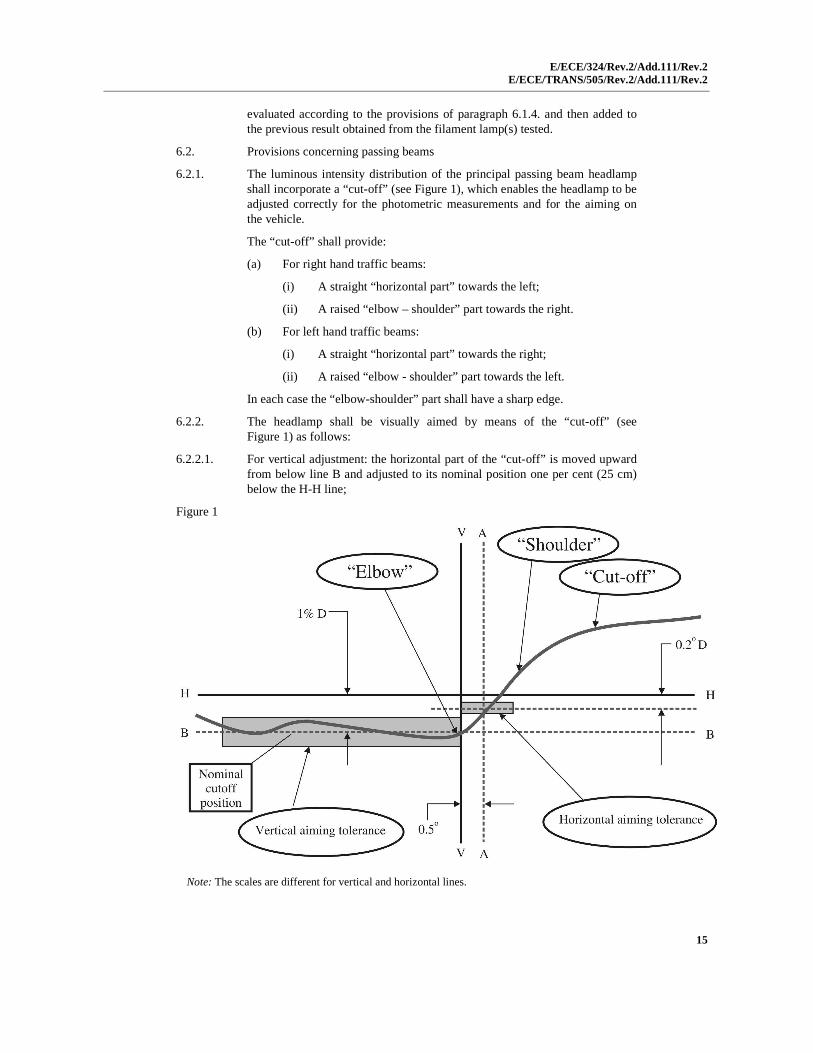
6.2.1. The luminous intensity distribution of the principal passing beam headlamp shall incorporate a “cut-off” (see Figure 1), which enables the headlamp to be adjusted correctly for the photometric measurements and for the aiming on the vehicle.
The “cut-off” shall provide:
(a) For right hand traffic beams:
(i) A straight “horizontal part” towards the left;
(ii) A raised “elbow – shoulder” part towards the right.
(b) For left hand traffic beams:
(i) A straight “horizontal part” towards the right;
(ii) A raised “elbow - shoulder” part towards the left.
In each case the “elbow-shoulder” part shall have a sharp edge.
6.2.2. The headlamp shall be visually aimed by means of the “cut-off” (see Figure 1) as follows:
6.2.2.1. For vertical adjustment: the horizontal part of the “cut-off” is moved upward from below line B and adjusted to its nominal position one per cent (25 cm) below the H-H line;
Figure 1
Note: The scales are different for vertical and horizontal lines.
E/ECE/324/Rev.2/Add.111/Rev.2 E/ECE/TRANS/505/Rev.2/Add.111/Rev.2
16
6.2.2.2. For horizontal adjustment: the “elbow – shoulder” part of the “cut-off” shall be moved:
For right hand traffic from right to left and shall be horizontally positioned after its movement so that:
(a) Above the line 0.2° D its “shoulder” shall not exceed the line A to the left;
(b) The line 0.2° D or below its “shoulder” should cross the line A; and
(c) The kink of the “elbow” should be primarily on the V-V line;
or
For left hand traffic from left to right and shall be horizontally positioned after its movement so that:
(a) Above the line 0.2 D its “shoulder” shall not exceed the line A to the right;
(b) On the line 0.2° or below its “shoulder” cross the line A; and
(c) The kink of the “elbow” should be primarily on the V-V line;
6.2.2.3. Where a headlamp so aimed does not meet the requirements set out in paragraphs 6.2.4. to 6.2.6. and 6.3., its alignment may be changed, provided that the axis of the beam is not displaced:
Horizontally from line A by more than:
(a) 0.5° to the left or 0.75° to the right, for right hand traffic; or
(b) 0.5° to the right or 0.75° to the left, for left hand traffic; and
Vertically not more than 0.25° up or down from line B.
6.2.2.4. If, however, vertical adjustment cannot be performed repeatedly to the required position within the tolerances described in paragraph 6.2.2.3. above, the instrumental method of Annex 9, paragraphs 2. and 3. shall be applied to test compliance with the required minimum quality of the “cut-off” and to perform the vertical and horizontal adjustment of the beam.
6.2.3. When so aimed, the headlamp, if its approval is sought solely for provision of a passing beam8, need comply only with the requirements set out in paragraphs 6.2.4. to 6.2.6. below; if it is intended to provide both a passing beam and a driving beam, it shall comply with the requirements set out in paragraphs 6.2.4. to 6.2.6. and 6.3.
8 Such a special “passing beam” headlamp may incorporate a driving beam not subject to requirements.
E/ECE/324/Rev.2/Add.111/Rev.2 E/ECE/TRANS/505/Rev.2/Add.111/Rev.2
17
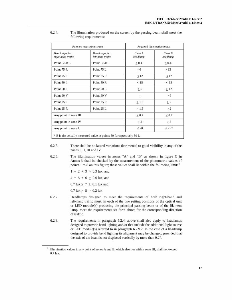
6.2.4. The illumination produced on the screen by the passing beam shall meet the following requirements:
6.2.5. There shall be no lateral variations detrimental to good visibility in any of the zones I, II, III and IV.
6.2.6. The illumination values in zones “A” and “B” as shown in figure C in Annex 3 shall be checked by the measurement of the photometric values of points 1 to 8 on this figure; these values shall lie within the following limits9:
1 + 2 + 3 > 0.3 lux, and
4 + 5 + 6 > 0.6 lux, and
0.7 lux > 7 > 0.1 lux and
0.7 lux > 8 > 0.2 lux
6.2.7. Headlamps designed to meet the requirements of both right-hand and left-hand traffic must, in each of the two setting positions of the optical unit or LED module(s) producing the principal passing beam or of the filament lamp, meet the requirements set forth above for the corresponding direction of traffic.
6.2.8. The requirements in paragraph 6.2.4. above shall also apply to headlamps designed to provide bend lighting and/or that include the additional light source or LED module(s) referred to in paragraph 6.2.9.2. In the case of a headlamp designed to provide bend lighting its alignment may be changed, provided that the axis of the beam is not displaced vertically by more than 0.2°.
9 Illumination values in any point of zones A and B, which also lies within zone III, shall not exceed 0.7 lux.
Point on measuring screen Required illumination in lux
Headlamps for right-hand traffic
Headlamps for left-hand traffic
Class A headlamp
Class B headlamp
Point B 50 L Point B 50 R < 0.4 < 0.4
Point 75 R Point 75 L > 6 > 12
Point 75 L Point 75 R < 12 < 12
Point 50 L Point 50 R < 15 < 15
Point 50 R Point 50 L > 6 > 12
Point 50 V Point 50 V - > 6
Point 25 L Point 25 R > 1.5 > 2
Point 25 R Point 25 L > 1.5 > 2
Any point in zone III < 0.7 < 0.7
Any point in zone IV > 2 > 3
Any point in zone I < 20 < 2E*
* E is the actually measured value in points 50 R respectively 50 L
E/ECE/324/Rev.2/Add.111/Rev.2 E/ECE/TRANS/505/Rev.2/Add.111/Rev.2
18
6.2.8.1. If bend lighting is obtained by:
6.2.8.1.1. Swivelling the passing beam or moving horizontally the kink of the elbow of the cut-off, the measurements shall be carried out after the complete headlamp assembly has been reaimed horizontally, e.g. by means of a goniometer;
6.2.8.1.2. Moving one or more optical parts of the headlamp without moving horizontally the kink of the elbow of the cut-off, measurements shall be carried out with these parts being in their extreme operating position;
6.2.8.1.3. Means of one additional filament light source or one or more LED module(s) without moving horizontally the kink of the elbow of the cut-off, measurements shall be carried out with this light source or LED module(s) activated.
6.2.9. Only one filament light source or one or more LED module(s) are permitted for the principal passing beam. Additional light sources or LED modules are permitted only as follows (see Annex 10):
6.2.9.1. One additional light source according to Regulation No. 37 or one or more additional LED module(s) may be used inside the passing beam headlamp to contribute to bend lighting;
6.2.9.2. One additional light source according to Regulation No. 37 and/or one or more LED module(s), inside the passing beam headlamp, may be used for the purposes of generating infrared radiation. It/they shall only be activated at the same time as the principal light source or LED module(s). In the event that the principal light source or (one of) the principal LED module(s) fails, this additional light source and/or LED module(s) shall be automatically switched off;
6.2.9.3. In the event of failure of an additional filament light source or one or more additional LED module(s), the headlamp shall continue to fulfil the requirements of the passing beam.
6.3. Provisions concerning driving beams
6.3.1. In the case of a headlamp designed to provide a driving beam and a passing beam, measurements of the illumination produced on the screen by the driving beam shall be taken with the same headlamp alignment as for measurements under paragraphs 6.2.4. to 6.2.6. above; in the case of a headlamp providing a driving beam only, it shall be so adjusted that the area of maximum illumination is centred on the point of intersection of lines H-H and V-V; such a headlamp need meet only the requirements referred to in paragraph 6.3. Where more than one light source is used to provide the driving beam, the combined functions shall be used to determine the maximum value of the illumination (EM).
6.3.2. Irrespective of the type of light source (LED module(s) or filament light source(s)) used to produce the principal passing beam, several light sources:
(a) Either filament light sources listed in Regulation No. 37; or
(b) LED module(s) may be used for each individual driving beam.
6.3.3. The illumination produced on the screen by the driving beam shall meet the following requirements.
E/ECE/324/Rev.2/Add.111/Rev.2 E/ECE/TRANS/505/Rev.2/Add.111/Rev.2
19
6.3.3.1. The point of intersection (HV) of lines hh and vv shall be situated within the isolux 80 per cent of maximum illumination. This maximum value (EM) shall not be less than 32 lux for Class A headlamps and 48 lux for Class B headlamps. The maximum value shall in no circumstances exceed 240 lux; in addition, in the case of a combined passing and driving headlamp, this maximum value shall not be more than 16 times the illumination measured for the passing beam at point 75 R (or 75 L).
6.3.3.1.1. The maximum intensity (IM) of the driving beam expressed in thousands of candelas shall be calculated by the formula:
IM = 0.625 EM
6.3.3.1.2. The reference mark (I'M) of this maximum intensity, referred to in paragraph 4.2.2.7. above, shall be obtained by the ratio:
MM
M E208,03
I'I ==
This value shall be rounded off to the value 7.5 - 10 - 12.5 - 17.5 - 20 - 25 - 27.5 - 30 - 37.5 - 40 - 45 - 50.
6.3.3.2. Starting from point HV, horizontally to the right and left, the illumination shall be not less than 16 lux for Class A headlamp and 24 lux for Class B headlamp up to a distance of 1.125 m and not less than 4 lux for Class A headlamp and 6 lux for Class B headlamp up to a distance of 2.25 m.
6.4. In the case of headlamps with adjustable reflector the requirements of paragraphs 6.2. and 6.3. are applicable for each mounting position indicated according to paragraph 2.1.3. For verification the following procedure shall be used:
6.4.1. Each applied position is realized on the test goniometer with respect to a line joining the centre of the light source and point HV on a aiming screen. The adjustable reflector is then moved into such a position that the light pattern on the screen corresponds to the aiming prescriptions of paragraphs 6.2.1. to 6.2.2.3. and/or 6.3.1.;
6.4.2. With the reflector initially fixed according to paragraph 6.4.1., the headlamp must meet the relevant photometric requirements of paragraphs 6.2. and 6.3.;
6.4.3. Additional tests are made after the reflector has been moved vertically +2° or at least into the maximum position, if less than 2°, from its initial position by means of the headlamps adjusting device. Having re-aimed the headlamp as a whole (by means of the goniometer for example) in the corresponding opposite direction the light output in the following directions shall be controlled and lie within the required limits:
Principal passing beam: points HV and 75 R (75 L respectively);
Driving beam: EM and point HV (percentage of EM).
6.4.4. If the applicant has not indicated more than one mounting position, the procedure of paragraphs 6.4.1. to 6.4.3. shall be repeated for all other positions;
6.4.5. If the applicant has not asked for special mounting positions, the headlamp shall be aimed for measurements of paragraphs 6.2. and 6.3. with the headlamps adjusting device in its mean position. The additional test of
E/ECE/324/Rev.2/Add.111/Rev.2 E/ECE/TRANS/505/Rev.2/Add.111/Rev.2
20
paragraph 6.4.3. shall be made with the reflector moved into its extreme positions (instead of +2°) by means of the headlamps adjusting device.
6.5. The screen illumination values mentioned in paragraphs 6.2.4. to 6.2.6. and 6.3. above shall be measured by means of a photo receptor, the effective area of which shall be contained within a square of 65 mm side.
7. Colour
7.1. The colour of the light emitted shall be white.
8. Gauging of discomfort
The discomfort caused by the passing beam of headlamps shall be gauged10.
C. Further administrative provisions
9. Modification of the headlamp type and extension of approval
9.1. Every modification of the headlamp type shall be notified to the Administrative Department which approved the headlamp type. The said department may then either:
9.1.1. Consider that the modifications made are unlikely to have appreciable adverse effects and that in any event the headlamp still complies with the requirements; or
9.1.2. Require a further test report from the Technical Service responsible for conducting the tests.
9.2. Confirmation or refusal of approval, specifying the alterations, shall be communicated by the procedure specified in paragraph 4.1.4. above to the Parties to the Agreement which apply this Regulation.
9.3. The Competent Authority issuing the extension of approval shall assign a series number to each communication form drawn up for such an extension and inform thereof the other Parties to the 1958 Agreement applying this Regulation by means of a communication form conforming to the model in Annex 1 to this Regulation.
10. Conformity of production
The conformity of production procedures shall comply with those set out in the Agreement, Appendix 2 (E/ECE/324-E/ECE/TRANS/505/Rev.2) with the following requirements:
10.1. Headlamps approved under this Regulation shall be so manufactured as to conform to the type approved by meeting the requirements set forth in paragraphs 6 and 7.
10 This requirement will be the subject of a recommendation to administrations.
E/ECE/324/Rev.2/Add.111/Rev.2 E/ECE/TRANS/505/Rev.2/Add.111/Rev.2
21
10.2. The minimum requirements for conformity of production control procedures set fourth in Annex 5 to this Regulation shall be complied with.
10.3. The minimum requirements for sampling by an inspector set forth in Annex 7 to this Regulation shall be complied with.
10.4. The authority which has granted type approval may at any time verify the conformity control methods applied in each production facility. The normal frequency of these verifications shall be once every two years.
10.5. Headlamps with apparent defects are disregarded.
10.6. The reference mark is disregarded.
11. Penalties for non-conformity of production
11.1. The approval granted in respect of a type of headlamp pursuant to this Regulation may be withdrawn if the requirements are not complied with or if a headlamp bearing the approval mark does not conform to the type approved.
11.2. If a Contracting Party to the Agreement applying this Regulation withdraws an approval it has previously granted, it shall forthwith so notify the other Contracting Parties applying this Regulation by means of a communication form conforming to the model in Annex 1 to this Regulation.
12. Production definitively discontinued
If the holder of the approval completely ceases to manufacture a type of headlamp approved in accordance with this Regulation, he shall so inform the authority which granted the approval. Upon receiving the relevant communication, that authority shall inform thereof the other Parties to the 1958 Agreement applying this Regulation by means of a communication form conforming to the model in Annex 1 to this Regulation.
13. Names and addresses of technical services responsible for conducting approval tests, and of administrative departments
The Parties to the 1958 Agreement applying this Regulation shall communicate to the United Nations Secretariat the names and addresses of the Technical Services responsible for conducting approval tests and of the Administrative Departments which grant approval and to which forms certifying approval or extension or refusal or withdrawal of approval, or production definitively discontinued, issued in other countries, are to be sent.
14. Transitional provisions
14.1. As from the official date of entry into force of Supplement 8, no Contracting Party applying this Regulation shall refuse to grant approvals under this Regulation as amended by Supplement 8 to the original version of the Regulation.

E/ECE/324/Rev.2/Add.111/Rev.2 E/ECE/TRANS/505/Rev.2/Add.111/Rev.2
22
14.2. As from 24 months from the entry into force of Supplement 8, Contracting Parties applying this Regulation shall grant approvals only if the headlamp type to be approved meets the requirements of this Regulation as amended by Supplement 8 to the original version of the Regulation.
14.3. Approvals granted under the preceding supplements to this Regulation shall remain valid.
14.4. Contracting Parties applying this Regulation shall continue to grant approvals on the basis of the preceding supplements to this Regulation, provided that the headlamps are intended as replacements for fitting to vehicles in use.
14.5. Contracting Parties applying this Regulation shall not refuse to grant extensions of approvals to the preceding supplements to this Regulation.
E/ECE/324/Rev.2/Add.111/Rev.2 E/ECE/TRANS/505/Rev.2/Add.111/Rev.2
Annex 1
23
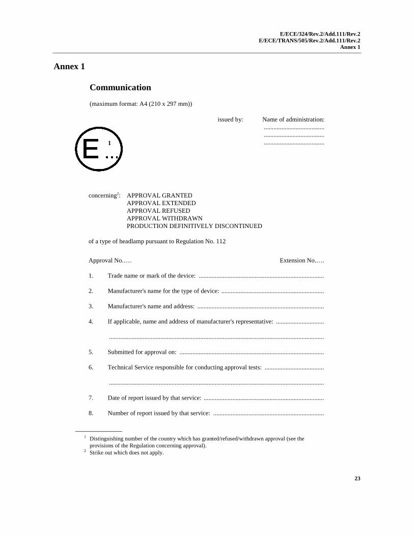
Annex 1
Communication
(maximum format: A4 (210 x 297 mm))
1
concerning2: APPROVAL GRANTED APPROVAL EXTENDED APPROVAL REFUSED APPROVAL WITHDRAWN PRODUCTION DEFINITIVELY DISCONTINUED
of a type of headlamp pursuant to Regulation No. 112
Approval No.…. Extension No.….
1. Trade name or mark of the device: ..............................................................................
2. Manufacturer's name for the type of device: ................................................................
3. Manufacturer's name and address: ...............................................................................
4. If applicable, name and address of manufacturer's representative: ..............................
......................................................................................................................................
5. Submitted for approval on: ..........................................................................................
6. Technical Service responsible for conducting approval tests: .....................................
......................................................................................................................................
7. Date of report issued by that service: ...........................................................................
8. Number of report issued by that service: .....................................................................
1 Distinguishing number of the country which has granted/refused/withdrawn approval (see the provisions of the Regulation concerning approval).
2 Strike out which does not apply.
issued by: Name of administration: ...................................... ...................................... ......................................
1 1

E/ECE/324/Rev.2/Add.111/Rev.2 E/ECE/TRANS/505/Rev.2/Add.111/Rev.2 Annex 1
24
9. Brief description:
Category as described by the relevant marking3: .........................................................
......................................................................................................................................
......................................................................................................................................
Number and category(s) of filament lamp(s): ..............................................................
......................................................................................................................................
......................................................................................................................................
Measures according to paragraph 5.8. of this Regulation: ...........................................
Number and specific identification code(s) of LED module(s) ...................................
Number and specific identification code(s) of electronic light source control gear(s)
Total objective luminous flux as described in paragraph 5.9. exceeds 2,000 lumen: yes/no/does not apply2
The adjustment of the cut-off has been determined at: 10 m/25 m/does not apply2
The determination of the minimum sharpness of the “cut-off” has been carried out at: 10 m/25 m/does not apply2.
10. Approval mark position: ..............................................................................................
11. Reason(s) for extension of approval: ...........................................................................
12. Approval granted/extended/refused//withdrawn2..........................................................
13. Place: ............................................................................................................................
14. Date: .............................................................................................................................
15. Signature: .....................................................................................................................
16. The list of documents deposited with the Administrative Service which has granted approval is annexed to this communication and may be obtained on request.
_________________
3 Indicate the appropriate marking selected from the list below:
C, C, C , R, R PL, CR, CR, CR , C/R, C/R, C/R , C/ , C/ , C/ ,
C, PL, C PL, C PL, CR PL, CR PL, CR PL, C/R PL, C/R PL, C/R PL,
C/PL, C/PL, C/PL
HC, HC, HC , HR, HR PL, HCR, HCR, HCR, HC/R, HC/R, HC/R, HC/, HC/, HC/,
HC PL, HC PL, HC PL, HCR PL, HCR PL, HCR PL, HC/R PL, HC/R PL, HC/R PL,
HC/PL, HC/PL, HC/PL
E/ECE/324/Rev.2/Add.111/Rev.2 E/ECE/TRANS/505/Rev.2/Add.111/Rev.2
Annex 2
25
Annex 2
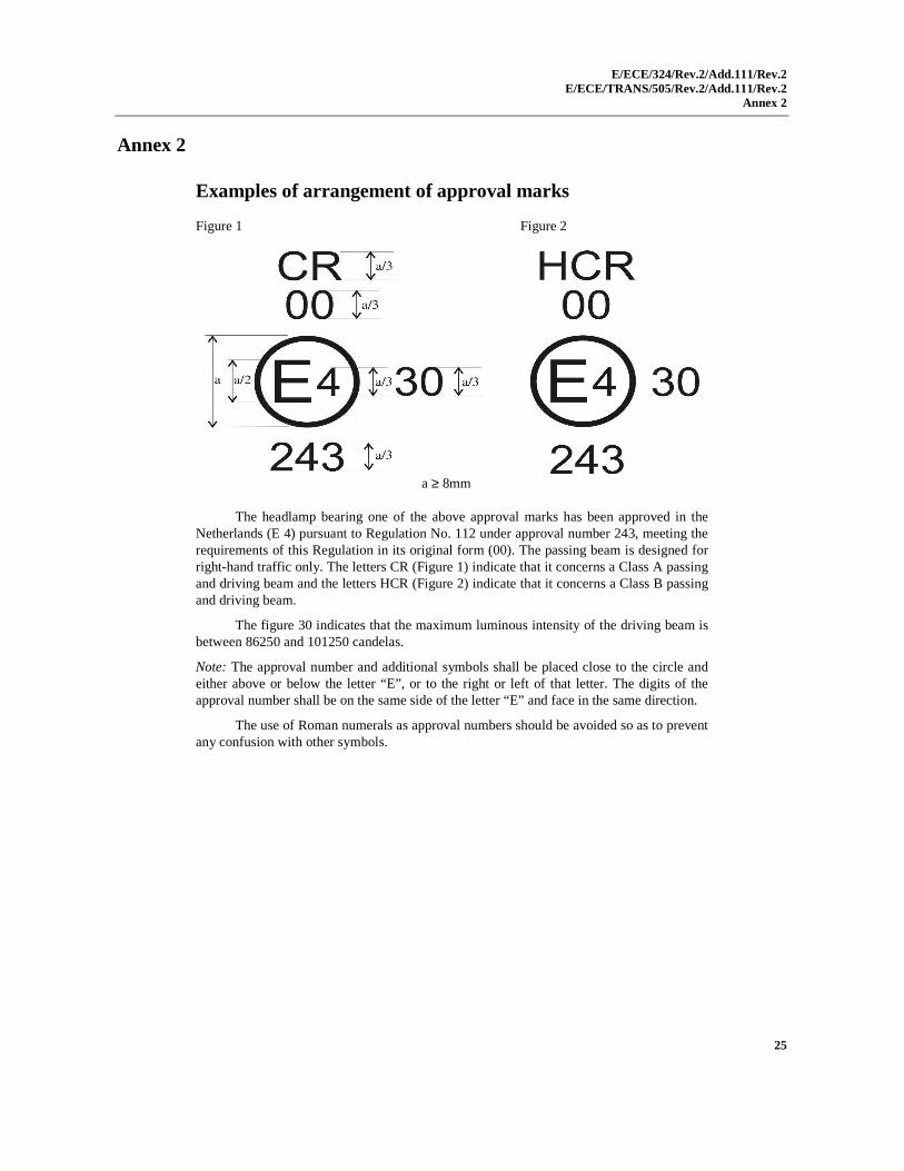
Examples of arrangement of approval marks
Figure 1 Figure 2
a ≥ 8mm
The headlamp bearing one of the above approval marks has been approved in the Netherlands (E 4) pursuant to Regulation No. 112 under approval number 243, meeting the requirements of this Regulation in its original form (00). The passing beam is designed for right-hand traffic only. The letters CR (Figure 1) indicate that it concerns a Class A passing and driving beam and the letters HCR (Figure 2) indicate that it concerns a Class B passing and driving beam.
The figure 30 indicates that the maximum luminous intensity of the driving beam is between 86250 and 101250 candelas.
Note: The approval number and additional symbols shall be placed close to the circle and either above or below the letter “E”, or to the right or left of that letter. The digits of the approval number shall be on the same side of the letter “E” and face in the same direction.
The use of Roman numerals as approval numbers should be avoided so as to prevent any confusion with other symbols.

E/ECE/324/Rev.2/Add.111/Rev.2 E/ECE/TRANS/505/Rev.2/Add.111/Rev.2 Annex 2
26
Figure 3 Figure 4a
Figure 4b
The headlamp bearing the above approval mark meets the requirements of this Regulation in respect of both the passing beam and the driving beam and is designed:
Figure 3: Class A for left hand traffic only.
Figures 4a and 4b: Class B for both traffic systems by means of an appropriate adjustment of the setting of the optical unit or the filament lamp on the vehicle.

E/ECE/324/Rev.2/Add.111/Rev.2 E/ECE/TRANS/505/Rev.2/Add.111/Rev.2
Annex 2
27
Figure 5 Figure 6
The headlamp bearing the above approval mark is a headlamp incorporating a lens of plastic material meeting the requirements of this Regulation in respect of the passing beam only and is designed:
Figure 5: Class A for both traffic systems.
Figure 6: Class B for right-hand traffic only.
Figure 7 Figure 8
The headlamp bearing the above approval mark is a headlamp meeting the requirements of this Regulation:
Figure 7: Class B in respect of the passing beam only and is designed for left-hand traffic only.
Figure 8: Class A in respect of the driving beam only.
E/ECE/324/Rev.2/Add.111/Rev.2 E/ECE/TRANS/505/Rev.2/Add.111/Rev.2 Annex 2
28
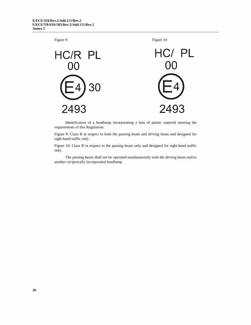
Figure 9 Figure 10
Identification of a headlamp incorporating a lens of plastic material meeting the requirements of this Regulation:
Figure 9: Class B in respect to both the passing beam and driving beam and designed for right-hand traffic only.
Figure 10: Class B in respect to the passing beam only and designed for right-hand traffic only.
The passing beam shall not be operated simultaneously with the driving beam and/or another reciprocally incorporated headlamp.
E/ECE/324/Rev.2/Add.111/Rev.2 E/ECE/TRANS/505/Rev.2/Add.111/Rev.2
Annex 2
29
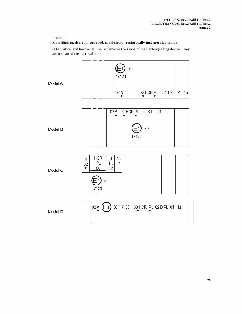
Figure 11 Simplified marking for grouped, combined or reciprocally incorporated lamps
(The vertical and horizontal lines schematize the shape of the light-signalling device. They are not part of the approval mark).
E/ECE/324/Rev.2/Add.111/Rev.2 E/ECE/TRANS/505/Rev.2/Add.111/Rev.2 Annex 2
30
Note: The four examples above correspond to a lighting device bearing an approval mark comprising:
A front position lamp approved in accordance with the 02 series of amendments to Regulation No. 7,
A headlamp, Class B, with a passing beam designed for right- and left-hand traffic and a driving beam with a maximum intensity comprised between 86 250 and 101 250 candelas (as indicated by the number 30), approved in accordance with the requirements of this Regulation in its original form (00) and incorporating a lens of plastic material,
A front fog lamp approved in accordance with the 02 series of amendments to Regulation No. 19 and incorporating a lens of plastic material,
A front direction indicator lamp of category 1a approved in accordance with the 01 series of amendments to Regulation No. 6.
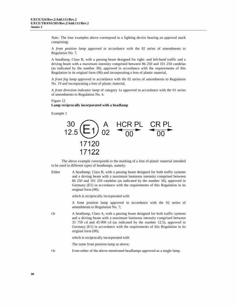
Figure 12 Lamp reciprocally incorporated with a headlamp Example 1
The above example corresponds to the marking of a lens of plastic material intended to be used in different types of headlamps, namely:
Either A headlamp, Class B, with a passing beam designed for both traffic systems and a driving beam with a maximum luminous intensity comprised between 86 250 and 101 250 candelas (as indicated by the number 30), approved in Germany (E1) in accordance with the requirements of this Regulation in its original form (00),
which is reciprocally incorporated with
A front position lamp approved in accordance with the 02 series of amendments to Regulation No. 7;
Or A headlamp, Class A, with a passing beam designed for both traffic systems and a driving beam with a maximum luminous intensity comprised between 33 750 cd and 45 000 cd (as indicated by the number 12.5), approved in Germany (E1) in accordance with the requirements of this Regulation in its original form (00),
which is reciprocally incorporated with
The same front position lamp as above;
Or Even either of the above-mentioned-headlamps approved as a single lamp.

E/ECE/324/Rev.2/Add.111/Rev.2 E/ECE/TRANS/505/Rev.2/Add.111/Rev.2
Annex 2
31
The main body of the headlamp shall bear the only valid approval number, for instance:
Example 2
The above example corresponds to the marking of a lens of plastic material used in a unit of two headlamps approved in France (E2) under approval number 81151, consisting of:
A headlamp, Class B, emitting a passing beam and a driving beam with a maximum luminous intensity between x and y candelas, meeting the requirements of this Regulation, and
A headlamp, Class B, emitting a driving beam designed for both traffic systems with a maximum luminous intensity between w and z candelas, meeting the requirements of this Regulation, the maximum luminous intensities of the driving beams as a whole being comprised between 86 250 and 101 250 candelas.
Figure 13
LED modules
MD E3 17325 The LED module bearing the light source module identification code shown above
has been approved together with a headlamp initially approved in Italy (E3) under approval number 17325.
E/ECE/324/Rev.2/Add.111/Rev.2 E/ECE/TRANS/505/Rev.2/Add.111/Rev.2 Annex 3
32
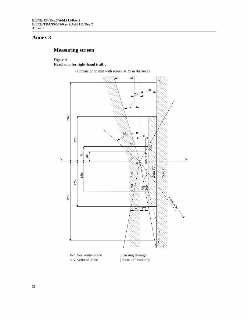
Annex 3
Measuring screen
Figure A Headlamp for right-hand traffic
(Dimension in mm with screen at 25 m distance)
h-h: horizontal plane ) passing through v-v: vertical plane ) focus of headlamp
E/ECE/324/Rev.2/Add.111/Rev.2 E/ECE/TRANS/505/Rev.2/Add.111/Rev.2
Annex 3
33
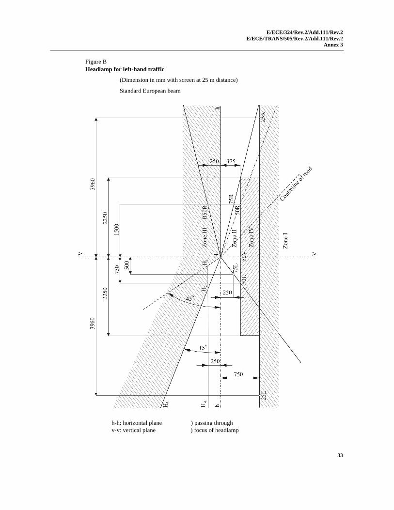
Figure B Headlamp for left-hand traffic
(Dimension in mm with screen at 25 m distance)
Standard European beam
h-h: horizontal plane ) passing through v-v: vertical plane ) focus of headlamp
E/ECE/324/Rev.2/Add.111/Rev.2 E/ECE/TRANS/505/Rev.2/Add.111/Rev.2 Annex 3
34
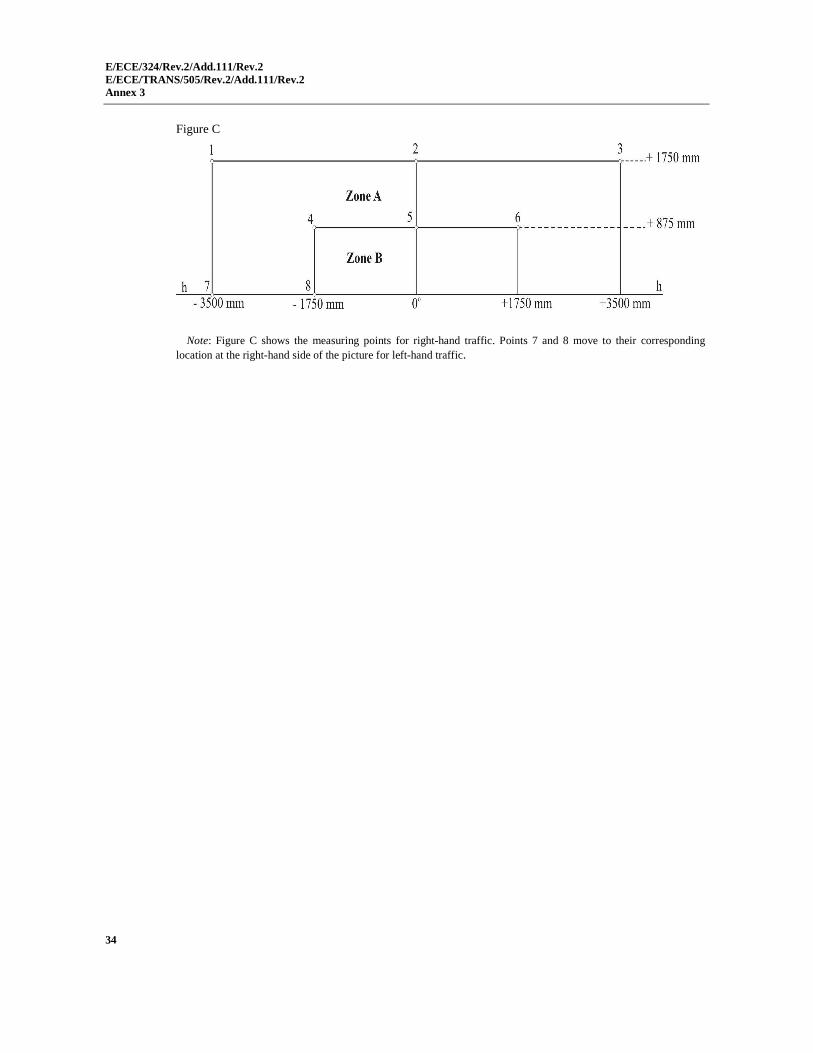
Figure C
Note: Figure C shows the measuring points for right-hand traffic. Points 7 and 8 move to their corresponding location at the right-hand side of the picture for left-hand traffic.
E/ECE/324/Rev.2/Add.111/Rev.2 E/ECE/TRANS/505/Rev.2/Add.111/Rev.2
Annex 4
35
Annex 4
Tests for stability of photometric performance of headlamps in operation
Tests on complete headlamps
Once the photometric values have been measured according to the prescriptions of this Regulation, in the point for Emax for driving beam and in points HV, 50 R, B 50 L for passing beam (or HV, 50 L, B 50 R for headlamps designed for left-hand traffic) a complete headlamp sample shall be tested for stability of photometric performance in operation. “Complete headlamp” shall be understood to mean the complete lamp itself including those surrounding body parts and lamps which could influence its thermal dissipation.
The tests shall be carried out:
(a) In a dry and still atmosphere at an ambient temperature of 23 °C +5 °C, the test sample being mounted on a base representing the correct installation on the vehicle;
(b) In case of replaceable light sources: using mass production filament light sources, which have been aged for at least one hour, or mass production gas-discharge light sources, which have been aged for at least 15 hours or mass production LED modules which have been aged for at least 48 hours and cooled down to ambient temperature before starting the tests as specified in this Regulation. The LED modules supplied by the applicant shall be used.
The measuring equipment shall be equivalent to that used during headlamp type approval tests.
The test sample shall be operated without being dismounted from or readjusted in relation to its test fixture. The light source used shall be a light source of the category specified for that headlamp.
1. Test for stability of photometric performance
1.1. Clean headlamp
The headlamp shall be operated for 12 hours as described in paragraph 1.1.1. and checked as prescribed in paragraph 1.1.2.
1.1.1. Test procedure1
The headlamp shall be operated for a period according to the specified time, so that:
1 For the test schedule see Annex 8 to this Regulation.
E/ECE/324/Rev.2/Add.111/Rev.2 E/ECE/TRANS/505/Rev.2/Add.111/Rev.2 Annex 4
36
1.1.1.1. (a) In the case where only one lighting function (driving or passing beam or front fog lamp) is to be approved, the corresponding filament and/or LED module(s) is (are) lit for the prescribed time2,
(b) In the case of a headlamp with a passing beam and one or more driving beams or in the case of a headlamp with a passing beam and a front fog lamp:
(i) The headlamp shall be subjected to the following cycle until the time specified is reached:
15 minutes, principal passing-beam filament or principal passing beam LED module(s) lit;
5 minutes, all filaments and/or LED module(s) lit.
(ii) If the applicant declares that the headlamp is to be used with only the passing beam lit or only the driving beam(s) lit3 at a time, the test shall be carried out in accordance with this condition, activating2 successively the passing beam half of the time and the driving beam(s) (simultaneously) for half the time specified in paragraph 1.1. above.
(c) In the case of a headlamp with a front fog lamp and one or more driving beams:
(i) The headlamp shall be subjected to the following cycle until the time specified is reached:
15 minutes, front fog lamp lit;
5 minutes, all filaments and/or all LED modules lit.
(ii) If the applicant declares that the headlamp is to be used with only the front fog lamp lit or only the driving beam(s) lit3 at a time, the test shall be carried out in accordance with this condition, activating2 successively the front fog lamp half of the time and the driving beam(s) (simultaneously) for half the time specified in paragraph 1.1. above.
(d) In the case of a headlamp with a passing beam, one or more driving beams and a front fog lamp:
(i) The headlamp shall be subjected to the following cycle until the time specified is reached:
15 minutes, principal passing-beam filament or principal passing beam LED module(s) lit;
5 minutes, all filaments and/or all LED modules lit.
2 When the tested headlamp includes signalling lamps, the latter shall be lit for the duration of the test, except for a daytime running lamp. In the case of a direction indicator lamp, it shall be lit in flashing mode with an on/ off time of approximately one to one.
3 Should two or more lamp filaments and/or LED module(s) be simultaneously lit when headlamp flashing is used, this shall not be considered as being normal use of the filaments and/or LED module(s).
E/ECE/324/Rev.2/Add.111/Rev.2 E/ECE/TRANS/505/Rev.2/Add.111/Rev.2
Annex 4
37
(ii) If the applicant declares that the headlamp is to be used with only the passing beam lit or only the driving beam(s)3 lit at a time, the test shall be carried out in accordance with this condition, activating2 successively the principal passing beam half of the time and the driving beam(s) for half the time specified in paragraph 1.1. above, while the front fog lamp is subjected to a cycle of 15 minutes off and 5 minutes lit for half of the time and during the operation of the driving beam;
(iii) If the applicant declares that the headlamp is to be used with only the passing beam lit or only the front fog lamp3 lit at a time, the test shall be carried out in accordance with this condition, activating2 successively the principal passing beam half of the time and the front fog lamp for half of the time specified in paragraph 1.1. above, while the driving beam(s) is(are) subjected to a cycle of 15 minutes off and 5 minutes lit for half of the time and during the operation of the principal passing beam;
(iv) If the applicant declares that the headlamp is to be used with only the passing beam lit or only the driving beam(s)3 lit or only the front fog lamp3 lit at a time, the test shall be carried out in accordance with this condition, activating2 successively the principal passing beam one third of the time, the driving beam(s) one third of the time and the front fog lamp for one third of the time specified in paragraph 1.1. above.
(e) In the case of a passing beam designed to provide bend lighting with the addition of a filament light source and/or one or more LED module(s), this light source and/or LED module(s) shall be switched on for one minute, and switched off for nine minutes during the activation of the passing beam only (see Annex 4 – Appendix 1).
1.1.1.2. Test voltage
The voltage shall be applied to the terminals of the test sample as follows:
(a) In case of replaceable filament light source(s) operated directly under vehicle voltage system conditions:
The test shall be performed at 6.3 V, 13.2 V or 28.0 V as applicable except if the applicant specifies that the test sample may be used at a different voltage. In this case, the test shall be carried out with the filament light source operated at the highest voltage that can be used.
(b) In case of replaceable gas discharge light source(s): The test voltage for the electronic light source control-gear is 13.2 +0.1 volts for 12 V vehicle voltage system, or otherwise specified in the application for approval.
(c) In the case of non-replaceable light source operated directly under vehicle voltage system conditions: All measurements on lighting units equipped with non-replaceable light sources (filament light sources and/ or others) shall be made at 6.3 V, 13.2 V or 28.0 V or at other voltages according to the vehicle voltage system as specified by the applicant respectively.
E/ECE/324/Rev.2/Add.111/Rev.2 E/ECE/TRANS/505/Rev.2/Add.111/Rev.2 Annex 4
38
(d) In the case of light sources, replaceable or non-replaceable, being operated independently from vehicle supply voltage and fully controlled by the system, or, in the case of light sources supplied by a supply and operating device, the test voltages as specified above shall be applied to the input terminals of that device. The test laboratory may require from the manufacturer the supply and operating device or a special power supply needed to supply the light source(s).
(e) LED module(s) shall be measured at 6.75 V, 13.2 V or 28.0 V respectively, if not otherwise specified within this Regulation. LED module(s) operated by an electronic light source control gear, shall be measured as specified by the applicant.
(f) Where signalling lamps are grouped, combined or reciprocally incorporated into the test sample and operating at voltages other than the nominal rated voltages of 6 V, 12 V or 24 V respectively, the voltage shall be adjusted as declared by the manufacturer for the correct photometric functioning of that lamp.
1.1.2. Test results
1.1.2.1. Visual inspection
Once the headlamp has been stabilized to the ambient temperature, the headlamp lens and the external lens, if any, shall be cleaned with a clean, damp cotton cloth. It shall then be inspected visually; no distortion, deformation, cracking or change in colour of either the headlamp lens or the external lens, if any, shall be noticeable.
1.1.2.2. Photometric test
To comply with the requirements of this Regulation, the photometric values shall be verified in the following points:
Passing beam:
50 R - B 50 L - HV for headlamps designed for right-hand traffic,
50 L - B 50 R - HV for headlamps designed for left-hand traffic.
Driving beam:
Point of Emax
Another aiming may be carried out to allow for any deformation of the headlamp base due to heat (the change of the position of the cut-off line is covered in paragraph 2 of this annex).
A 10 per cent discrepancy between the photometric characteristics and the values measured prior to the test is permissible including the tolerances of the photometric procedure.
1.2. Dirty headlamp
After being tested as specified in paragraph 1.1. above, the headlamp shall be operated for one hour as described in paragraph 1.1.1., after being prepared as prescribed in paragraph 1.2.1., and checked as prescribed in paragraph 1.1.2.

E/ECE/324/Rev.2/Add.111/Rev.2 E/ECE/TRANS/505/Rev.2/Add.111/Rev.2
Annex 4
39
1.2.1. Preparations of the headlamp
1.2.1.1. Test mixture
1.2.1.1.1. For headlamp with the outside lens in glass:
The mixture of water and a polluting agent to be applied to the headlamp shall be composed of:
9 parts by weight of silica sand with a particle size of 0-100 µm,
1 part by weight of vegetal carbon dust (beechwood) with a particle size of 0-100 µm,
0.2 parts by weight of NaCMC4, and
An appropriate quantity of distilled water, with a conductivity of ≤ 1 mS/m.
The mixture must not be more than 14 days old.
1.2.1.1.2. For headlamp with outside lens in plastic material:
The mixture of water and polluting agent to be applied to the headlamp shall be composed of:
9 parts by weight of silica sand with a particle size of 0-100 µm,
1 part by weight of vegetal carbon dust (beechwood) with a particle size of 0-100 µm,
0.2 part by weight of NaCMC4,
13 parts by weight of distilled water with a conductivity of ≤ 1 mS/m, and
2 +1 parts by weight of surface-actant5
The mixture must not be more than 14 days old.
1.2.1.2. Application of the test mixture to the headlamp
The test mixture shall be uniformly applied to the entire light-emitting surface of the headlamp and then left to dry. This procedure shall be repeated until the illumination value has dropped to 15-20 per cent of the values measured for each following point under the conditions described in this annex:
Point of Emax in passing beam/driving beam and in driving beam only,
50 R and 50 V6 for a passing lamp only, designed for right-hand traffic,
50 L and 50 V6 for a passing lamp only, designed for left-hand traffic.
4 NaCMC represents the sodium salt of carboxymethylcellulose, customarily referred to as CMC. The NaCMC used in the dirt mixture shall have a degree of substitution (DS) of 0.6-0.7 and a viscosity of 200-300 cP for a 2 per cent solution at 20° C.
5 The tolerance on quantity is due to the necessity of obtaining a dirt that correctly spreads out on all the plastic lens.
6 Point 50 V is situated 375 mm below HV on the vertical line v-v on the screen at 25 m distance.
E/ECE/324/Rev.2/Add.111/Rev.2 E/ECE/TRANS/505/Rev.2/Add.111/Rev.2 Annex 4
40
2. Test for change in vertical position of the cut-off line under the influence of heat
This test consists of verifying that the vertical drift of the cut-off line under the influence of heat does not exceed a specified value for an operating passing lamp.
The headlamp tested in accordance with paragraph 1., shall be subjected to the test described in paragraph 2.1., without being removed from or readjusted in relation to its test fixture.
2.1. Test
The test shall be carried out in a dry and still atmosphere at an ambient temperature of 23 °C +5 °C.
Using a mass production filament lamp or the LED module(s) as submitted with the headlamp, which has (have) been aged for at least one hour, the headlamp shall be operated on the principal passing beam without being dismounted from or readjusted in relation to its test fixture. (For the purpose of this test, the voltage shall be adjusted as specified in paragraph 1.1.1.2.). The position of the cut-off line in its horizontal part (between vv and the vertical line passing through point B 50 L for right-hand traffic or B 50 R for left-hand traffic) shall be verified 3 minutes (r3) and 60 minutes (r60) respectively after operation.
The measurement of the variation in the cut-off line position as described above shall be carried out by any method giving acceptable accuracy and reproducible results.
2.2. Test results
2.2.1. The result in milliradians (mrad) shall be considered as acceptable for a passing lamp, only when the absolute value ∆rI = | r3 - r60 | recorded on the headlamp is not more than 1.0 mrad (∆rI < 1.0 mrad).
2.2.2. However, if this value is more than 1.0 mrad but not more than 1.5 mrad (1.0 mrad < ∆rI < 1.5 mrad) a second headlamp shall be tested as described in paragraph 2.1. after being subjected three consecutive times to the cycle as described below, in order to stabilize the position of mechanical parts of the headlamp on a base representative of the correct installation on the vehicle:
Operation of the passing beam for one hour, (the voltage shall be adjusted as specified in paragraph 1.1.1.2.),
Period of rest for one hour.
The headlamp type shall be considered as acceptable if the mean value of the absolute values ∆rI measured on the first sample and ∆rII measured on the second sample is not more than 1.0 mrad.
≤∆+∆mrad1
2
rr III
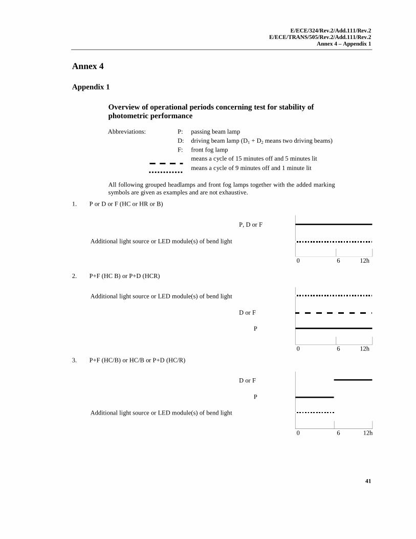
E/ECE/324/Rev.2/Add.111/Rev.2 E/ECE/TRANS/505/Rev.2/Add.111/Rev.2
Annex 4 – Appendix 1
41
Annex 4
Appendix 1
Overview of operational periods concerning test for stability of photometric performance
Abbreviations: P: passing beam lamp
D: driving beam lamp (D1 + D2 means two driving beams)
F: front fog lamp means a cycle of 15 minutes off and 5 minutes lit
means a cycle of 9 minutes off and 1 minute lit
All following grouped headlamps and front fog lamps together with the added marking symbols are given as examples and are not exhaustive.
1. P or D or F (HC or HR or B)
P, D or F
Additional light source or LED module(s) of bend light
0 6 12h
2. P+F (HC B) or P+D (HCR)
Additional light source or LED module(s) of bend light
D or F
P
0 6 12h
3. P+F (HC/B) or HC/B or P+D (HC/R)
D or F
P
Additional light source or LED module(s) of bend light
0 6 12h
E/ECE/324/Rev.2/Add.111/Rev.2 E/ECE/TRANS/505/Rev.2/Add.111/Rev.2 Annex 5
42
Annex 5
Minimum requirements for conformity of production control procedures
1. General
1.1. The conformity requirements shall be considered satisfied from a mechanical and a geometrical standpoint, if the differences do not exceed inevitable manufacturing deviations within the requirements of this Regulation. This condition also applies to colour.
1.2. With respect to photometric performances, the conformity of mass-produced headlamps shall not be contested if, when testing photometric performances of any headlamp chosen at random and equipped with a standard (étalon) filament lamp and/or LED module(s), as present in the lamp:
1.2.1. No measured value deviates unfavourably by more than 20 per cent from the value prescribed in this Regulation. For values B 50 L (or R) and zone III, the maximum unfavourable deviation may be respectively:
B 50 L (or R): 0.2 lx equivalent 20 per cent
0.3 lx equivalent 30 per cent
Zone III 0.3 lx equivalent 20 per cent
0.45 lx equivalent 30 per cent
1.2.2. Or if
1.2.2.1. For the passing beam, the values prescribed in this Regulation are met at HV (with a tolerance of + 0.2 lx) and related to that aiming at least one point of each area delimited on the measuring screen (at 25 m) by a circle 15 cm in radius around points B 50 L (or R)1 (with a tolerance of + 0.1 lx), 75 R (or L), 50 V, 25 R, 25 L, and in the entire area of zone IV which is not more than 22.5 cm above line 25 R and 25 L;
1.2.2.2. And if, for the driving beam, HV being situated within the isolux 0.75 Emax, a tolerance of + 20 per cent for maximum values and -20 per cent for minimum values is observed for the photometric values at any measuring point specified in paragraph 6.3.2. of this Regulation.
1.2.3. If the results of the test described above do not meet the requirements, the alignment of the headlamp may be changed, provided that the axis of the beam is not displaced laterally by more than 1° to the right or left.
1.2.4. If in the case of a lamp equipped with a replaceable filament light source the results of the tests described above do not meet the requirements, tests shall be repeated using another standard (étalon) filament lamp.
1.3. With respect to the verification of the change in vertical position of the cut-off line under the influence of heat, the following procedure shall be applied:
1 Letters in brackets refer to headlamps intended for left-hand traffic.

E/ECE/324/Rev.2/Add.111/Rev.2 E/ECE/TRANS/505/Rev.2/Add.111/Rev.2
Annex 5
43
One of the sampled headlamps shall be tested according to the procedure described in paragraph 2.1. of Annex 4 after being subjected three consecutive times to the cycle described in paragraph 2.2.2. of Annex 4.
The headlamp shall be considered as acceptable if ∆r does not exceed 1.5 mrad.
If this value exceeds 1.5 mrad but is not more than 2.0 mrad, a second sample shall be subjected to the test after which the mean of the absolute values recorded on both samples shall not exceed 1.5 mrad.
1.4. If, however, vertical adjustment cannot be performed repeatedly to the required position within the tolerances described in paragraph 6.2.2.3. of this Regulation, one sample shall be tested according to the procedure described in paragraphs 2. and 3. of Annex 9.
2. Minimum requirements for verification of conformity by the manufacturer
For each type of headlamp the holder of the approval mark shall carry out at least the following tests, at appropriate intervals. The tests shall be carried out in accordance with the provision of this Regulation.
If any sampling shows non-conformity with regard to the type of test concerned, further samples shall be taken and tested. The manufacturer shall take steps to ensure the conformity of the production concerned.
2.1. Nature of tests
Tests of conformity in this Regulation shall cover the photometric characteristics and the verification of the change in vertical position of the cut-off line under the influence of heat.
2.2. Methods used in tests
2.2.1. Tests shall generally be carried out in accordance with the methods set out in this Regulation.
2.2.2. In any test of conformity carried out by the manufacturer, equivalent methods may be used with the consent of the Competent Authority responsible for approval tests. The manufacturer is responsible for proving that the applied methods are equivalent to those laid down in this Regulation.
2.2.3. The application of paragraphs 2.2.1. and 2.2.2. requires regular calibration of test apparatus and its correlation with measurement made by a Competent Authority.
2.2.4. In all cases the reference methods shall be those of this Regulation, particular for the purpose of administrative verification and sampling.
2.3. Nature of sampling
Samples of headlamps shall be selected at random from the production of a uniform batch. A uniform batch means a set of headlamps of the same type, defined according to the production methods of the manufacturer.
The assessment shall, in general, cover series production from individual factories. However, a manufacturer may group together records concerning the same type from several factories provided these operate under the same quality system and quality management.

E/ECE/324/Rev.2/Add.111/Rev.2 E/ECE/TRANS/505/Rev.2/Add.111/Rev.2 Annex 5
44
2.4. Measured and recorded photometric characteristics
The sampled headlamps shall be subjected to photometric measurements at the points provided for in the Regulation, the reading being limited at the points Emax, HV2, HL, HR3 in the case of a driving beam, and to points B 50 L (or R), HV, 50 V, 75 R (or L) and 25 L (or R) in the case of the passing beam (see figure in Annex 3).
2.5. Criteria governing acceptability
The manufacturer is responsible for carrying out a statistical study of the test results and for defining, in agreement with the Competent Authority, criteria governing acceptability of his products in order to meet the specification laid down for verification of conformity of products in paragraph 10.1. of this Regulation.
The criteria governing acceptability shall be such that, with a confidence level of 95 per cent, the minimum probability of passing a spot check in accordance with Annex 7 (first sampling) would be 0.95.
2 When the driving beam is reciprocally incorporated with the passing beam, HV in the case of the driving beam shall be the same measuring point as in the case of the passing beam.
3 HL and HR: points “hh” located at 1.125 m to the left and to the right of point HV respectively.

E/ECE/324/Rev.2/Add.111/Rev.2 E/ECE/TRANS/505/Rev.2/Add.111/Rev.2
Annex 6
45
Annex 6
Requirements for lamps incorporating lenses of plastic material – Testing of lens or material samples and of complete lamps
1. General specifications
1.1. The samples supplied pursuant to paragraph 2.2.4. of this Regulation shall satisfy the specifications indicated in paragraphs 2.1. to 2.5. below.
1.2. The two samples of complete lamps supplied pursuant to paragraph 2.2.3. of this Regulation and incorporating lenses of plastic material shall, with regard to the lens material, satisfy the specifications indicated in paragraph 2.6. below.
1.3. The samples of lenses of plastic material or samples of material shall be subjected, with the reflector to which they are intended to be fitted (where applicable), to approval tests in the chronological order indicated in table A reproduced in Appendix 1 to this annex.
1.4. However, if the lamp manufacturer can prove that the product has already passed the tests prescribed in paragraphs 2.1. to 2.5. below, or the equivalent tests pursuant to another regulation, those tests need not be repeated; only the tests prescribed in Appendix 1, table B, shall be mandatory.
2. Tests
2.1. Resistance to temperature changes
2.1.1. Tests
Three new samples (lenses) shall be subjected to five cycles of temperature and humidity (RH = relative humidity) change in accordance with the following programme:
3 hours at 40 °C +2 °C and 85-95 per cent RH;
1 hour at 23 °C +5 °C and 60-75 per cent RH;
15 hours at -30 °C +2 °C;
1 hour at 23 °C +5 °C and 60-75 per cent RH;
3 hours at 80 °C +2 °C;
1 hour at 23 °C +5°C and 60-75 per cent RH;
Before this test, the samples shall be kept at 23 °C +5 °C and 60-75 per cent RH for at least four hours.
Note: The periods of one hour at 23 °C +5 °C shall include the periods of transition from one temperature to another which are needed in order to avoid thermal shock effects.
E/ECE/324/Rev.2/Add.111/Rev.2 E/ECE/TRANS/505/Rev.2/Add.111/Rev.2 Annex 6
46
2.1.2. Photometric measurements
2.1.2.1. Method
Photometric measurements shall be carried out on the samples before and after the test.
These measurements shall be made using a standard (étalon) lamp and/or LED module(s), as present in the headlamp, at the following points:
B 50 L and 50 R for the passing beam of a passing lamp or a passing/driving lamp (B 50 R and 50 L in the case of headlamps intended for left-hand traffic);
Emax route for the driving beam of a driving lamp or a passing/driving lamp.
2.1.2.2. Results
The variation between the photometric values measured on each sample before and after the test shall not exceed 10 per cent including the tolerances of the photometric procedure.
2.2. Resistance to atmospheric and chemical agents
2.2.1. Resistance to atmospheric agents
Three new samples (lenses or samples of material) shall be exposed to radiation from a source having a spectral energy distribution similar to that of a black body at a temperature between 5,500 K and 6,000 K. Appropriate filters shall be placed between the source and the samples so as to reduce as far as possible radiations with wave lengths smaller than 295 nm and greater than 2,500 nm. The samples shall be exposed to an energetic illumination of 1,200 W/m2 +200 W/m2 for a period such that the luminous energy that they receive is equal to 4,500 MJ/m2 +200 MJ/m2. Within the enclosure, the temperature measured on the black panel placed on a level with the samples shall be 50 °C +5 °C. In order to ensure a regular exposure, the samples shall revolve around the source of radiation at a speed between 1 and 5 1/min.
The samples shall be sprayed with distilled water of conductivity lower than 1 mS/m at a temperature of 23 °C +5 °C, in accordance with the following cycle:
spraying: 5 minutes; drying: 25 minutes.
2.2.2. Resistance to chemical agents
After the test described in paragraph 2.2.1. above and the measurement described in paragraph 2.2.3.1. below have been carried out, the outer face of the said three samples shall be treated as described in paragraph 2.2.2.2. with the mixture defined in paragraph 2.2.2.1. below.
2.2.2.1. Test mixture
The test mixture shall be composed of 61.5 per cent n-heptane, 12.5 per cent toluene, 7.5 per cent ethyl tetrachloride, 12.5 per cent trichloroethylene and 6 per cent xylene (volume per cent).

E/ECE/324/Rev.2/Add.111/Rev.2 E/ECE/TRANS/505/Rev.2/Add.111/Rev.2
Annex 6
47
2.2.2.2. Application of the test mixture
Soak a piece of cotton cloth (as per ISO 105) until saturation with the mixture defined in paragraph 2.2.2.1. above and, within 10 seconds, apply it for 10 minutes to the outer face of the sample at a pressure of 50 N/cm2, corresponding to an effort of 100 N applied on a test surface of 14 x 14 mm.
During this 10-minute period, the cloth pad shall be soaked again with the mixture so that the composition of the liquid applied is continuously identical with that of the test mixture prescribed.
During the period of application, it is permissible to compensate the pressure applied to the sample in order to prevent it from causing cracks.
2.2.2.3. Cleaning
At the end of the application of the test mixture, the samples shall be dried in the open air and then washed with the solution described in paragraph 2.3.1. (Resistance to detergents)
23 °C +5 °C.
Afterwards the samples shall be carefully rinsed with distilled water containing not more than 0.2 per cent impurities at 23 °C +5 °C and then wiped off with a soft cloth.
2.2.3. Results
2.2.3.1. After the test of resistance to atmospheric agents, the outer face of the samples shall be free from cracks, scratches, chipping and deformation, and
the mean variation in transmission ∆t = 2
32
T
TT −, measured on the three
samples according to the procedure described in Appendix 2 to this annex shall not exceed 0.020 (∆tm < 0.020).
2.2.3.2. After the test of resistance to chemical agents, the samples shall not bear any traces of chemical staining likely to cause a variation of flux diffusion, whose
mean variation ∆d = 2
45
T
TT −, measured on the three samples according to
the procedure described in Appendix 2 to this annex shall not exceed 0.020 (∆dm < 0.020).
2.2.4. Resistance to light source radiations
The following test shall be done:
Flat samples of each light transmitting plastic component of the headlamp are exposed to the light of the LED module(s). The parameters such as angles and distances of these samples shall be the same as in the headlamp. These samples shall have the same colour and surface treatment, if any, as the parts of the headlamp.
After 1,500 hours of continuous operation, the colorimetric specifications of the transmitted light must be met, and the surfaces of the samples shall be free of cracks, scratches, scalings or deformation.
E/ECE/324/Rev.2/Add.111/Rev.2 E/ECE/TRANS/505/Rev.2/Add.111/Rev.2 Annex 6
48
2.3. Resistance to detergents and hydrocarbons
2.3.1. Resistance to detergents
The outer face of three samples (lenses or samples of material) shall be heated to 50 °C +5 °C and then immersed for five minutes in a mixture maintained at 23 °C +5 °C and composed of 99 parts distilled water containing not more than 0.02 per cent impurities and one part alkylaryl sulphonate.
At the end of the test, the samples shall be dried at 50 °C +5 °C. The surface of the samples shall be cleaned with a moist cloth.
2.3.2. Resistance to hydrocarbons
The outer face of these three samples shall then be lightly rubbed for one minute with a cotton cloth soaked in a mixture composed of 70 per cent n-heptane and 30 per cent toluene (volume per cent), and shall then be dried in the open air.
2.3.3. Results
After the above two tests have been performed successively, the mean value
of the variation in transmission ∆t = 2
32
T
TT −, measured on the three
samples according to
The procedure described in Appendix 2 to this annex shall not exceed 0.010 (∆tm < 0.010).
2.4. Resistance to mechanical deterioration
2.4.1. Mechanical deterioration method
The outer face of the three new samples (lenses) shall be subjected to the uniform mechanical deterioration test by the method described in Appendix 3 to this annex.
2.4.2. Results
After this test, the variations:
in transmission: ∆t = 2
32
T
TT −,
and in diffusion: ∆t = 2
45
T
TT −,
shall be measured according to the procedure described in Appendix 2 in the area specified in paragraph 2.2.4.1.1. of this Regulation. The mean value of the three samples shall be such that:
∆tm < 0.100;
∆dm < 0.050.

E/ECE/324/Rev.2/Add.111/Rev.2 E/ECE/TRANS/505/Rev.2/Add.111/Rev.2
Annex 6
49
2.5. Test of adherence of coatings, if any
2.5.1. Preparation of the sample
A surface of 20 mm x 20 mm in area of the coating of a lens shall be cut with a razor blade or a needle into a grid of squares approximately 2 mm x 2 mm. The pressure on the blade or needle shall be sufficient to cut at least the coating.
2.5.2. Description of the test
Use an adhesive tape with a force adhesion of 2 N/(cm of width) ±20 per cent measured under the standardized conditions specified in Appendix 4 to this annex. This adhesive tape, which shall be at least 25 mm wide, shall be pressed for at least five minutes to the surface prepared as prescribed in paragraph 2.5.1.
Then the end of the adhesive tape shall be loaded in such a way that the force of adhesion to the surface considered is balanced by a force perpendicular to that surface. At this stage, the tape shall be torn off at a constant speed of 1.5 m/s +0.2 m/s.
2.5.3. Results
There shall be no appreciable impairment of the gridded area. Impairments at the intersections between squares or at the edges of the cuts shall be permitted, provided that the impaired area does not exceed 15 per cent of the gridded surface.
2.6. Tests of the complete headlamp incorporating a lens of plastic material
2.6.1. Resistance to mechanical deterioration of the lens surface
2.6.1.1. Tests
The lens of lamp sample No. 1 shall be subjected to the test described in paragraph 2.4.1. above.
2.6.1.2. Results
After the test, the results of photometric measurements carried out on the headlamp in accordance with this Regulation shall not exceed by more than 30 per cent the maximum values prescribed at points B 50 L and HV and not be more than 10 per cent below the minimum values prescribed at point 75 R (in the case of headlamps intended for left-hand traffic, the points to be considered are B 50 R, HV and 75 L).
2.6.2. Test of adherence of coatings, if any
The lens of lamp sample No. 2 shall be subjected to the test described in paragraph 2.5. above.
3. Verification of the conformity of production
3.1. With regard to the materials used for the manufacture of lenses, the lamps of a series shall be recognized as complying with this Regulation if:
3.1.1. After the test for resistance to chemical agents and the test for resistance to detergents and hydrocarbons, the outer face of the samples exhibits no cracks, chipping or deformation visible to the naked eye (see paras. 2.2.2., 2.3.1. and 2.3.2.);
E/ECE/324/Rev.2/Add.111/Rev.2 E/ECE/TRANS/505/Rev.2/Add.111/Rev.2 Annex 6
50
3.1.2. After the test described in paragraph 2.6.1.1., the photometric values at the points of measurement considered in paragraph 2.6.1.2. are within the limits prescribed for conformity of production by this Regulation.
3.2. If the test results fail to satisfy the requirements, the tests shall be repeated on another sample of headlamps selected at random.

E/ECE/324/Rev.2/Add.111/Rev.2 E/ECE/TRANS/505/Rev.2/Add.111/Rev.2
Annex 6 – Appendix 1
51
Annex 6
Appendix 1
Chronological order of approval tests
A. Tests on plastic materials (lenses or samples of material supplied pursuant to paragraph 2.2.4. of this Regulation).
Samples Lenses or samples of material Lenses
Tests 1 2 3 4 5 6 7 8 9 10 11 12 13 14
1.1. Limited photometry (A.6, para. 2.1.2.) X X X
1.1.1. Temperature change (A.6, para. 2.1.1.) X X X
1.2. Limited photometry (A.6, para. 2.1.2.) X X X
1.2.1. Transmission measurement X X X X X X X X X
1.2.2. Diffusion measurement X X X X X X
1.3. Atmospheric agents (A.6, para. 2.2.1.) X X X
1.3.1. Transmission measurement X X X
1.4. Chemical agents (A.6, para.2.2.2.) X X X
1.4.1. Diffusion measurements X X X
1.5. Detergents (A.6, para. 2.3.1.) X X X
1.6. Hydrocarbons (A.6, para. 2.3.2.) X X X
1.6.1. Transmission measurement X X X
1.7. Deterioration (A.6, para. 2.4.1.) X X X
1.7.1. Transmission measurement X X X
1.7.2. Diffusion measurement X X X
1.8. Adherence (A.6, para. 2.5.) X
1.9 Resistance to light source radiations (A.6, para. 2.2.4.)
X
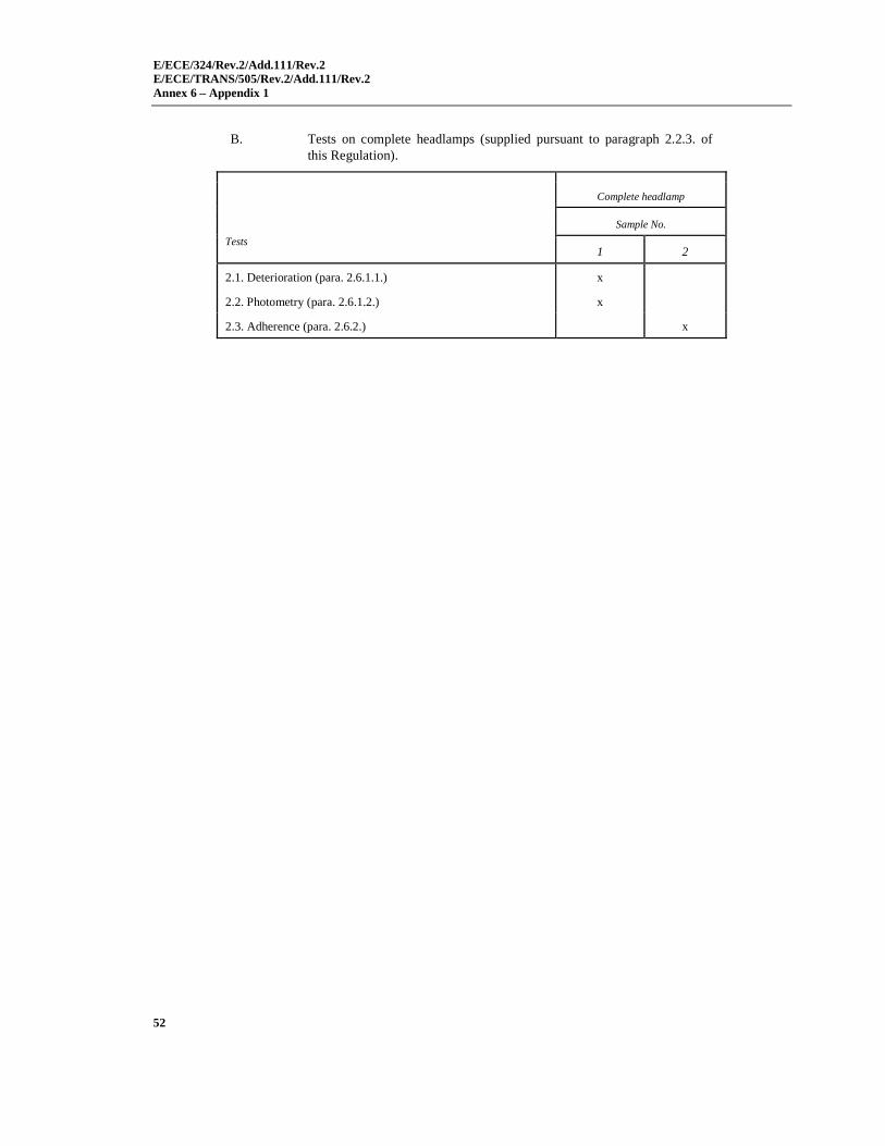
E/ECE/324/Rev.2/Add.111/Rev.2 E/ECE/TRANS/505/Rev.2/Add.111/Rev.2 Annex 6 – Appendix 1
52
B. Tests on complete headlamps (supplied pursuant to paragraph 2.2.3. of this Regulation).
Complete headlamp
Sample No.
Tests 1 2
2.1. Deterioration (para. 2.6.1.1.) x
2.2. Photometry (para. 2.6.1.2.) x
2.3. Adherence (para. 2.6.2.) x
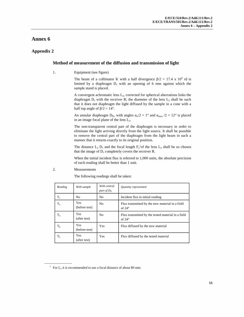
E/ECE/324/Rev.2/Add.111/Rev.2 E/ECE/TRANS/505/Rev.2/Add.111/Rev.2
Annex 6 – Appendix 2
53
Annex 6
Appendix 2
Method of measurement of the diffusion and transmission of light
1. Equipment (see figure)
The beam of a collimator K with a half divergence β/2 = 17.4 x 10⁴ rd is limited by a diaphragm Dτ with an opening of 6 mm against which the sample stand is placed.
A convergent achromatic lens L2, corrected for spherical aberrations links the diaphragm Dτ with the receiver R; the diameter of the lens L2 shall be such that it does not diaphragm the light diffused by the sample in a cone with a half top angle of β/2 = 14°.
An annular diaphragm DD, with angles αo/2 = 1° and αmax /2 = 12° is placed in an image focal plane of the lens L2.
The non-transparent central part of the diaphragm is necessary in order to eliminate the light arriving directly from the light source. It shall be possible to remove the central part of the diaphragm from the light beam in such a manner that it returns exactly to its original position.
The distance L2 Dτ and the focal length F21of the lens L2 shall be so chosen
that the image of Dτ completely covers the receiver R.
When the initial incident flux is referred to 1,000 units, the absolute precision of each reading shall be better than 1 unit.
2. Measurements
The following readings shall be taken:
Reading With sample With central
part of DD Quantity represented
T1 No No Incident flux in initial reading
T2 Yes (before test)
No Flux transmitted by the new material in a field of 24°
T3 Yes (after test)
No Flux transmitted by the tested material in a field of 24°
T4 Yes (before test)
Yes Flux diffused by the new material
T5 Yes (after test)
Yes Flux diffused by the tested material
1 For L2 it is recommended to use a focal distance of about 80 mm.
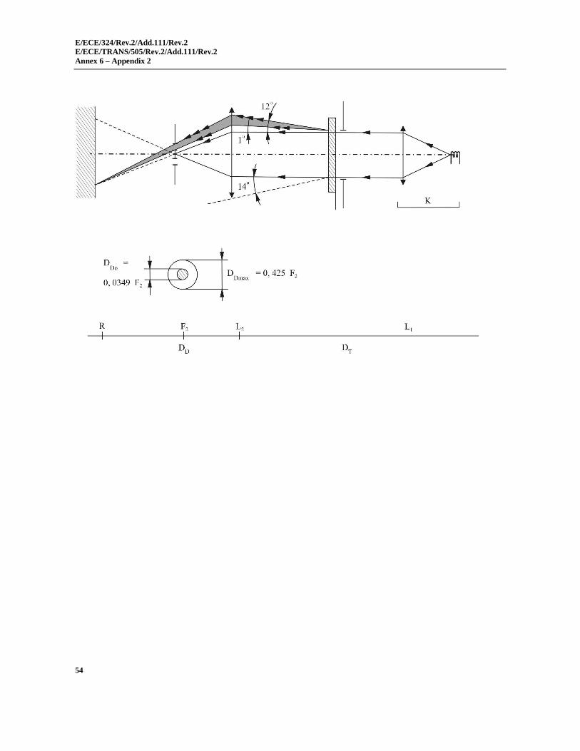
E/ECE/324/Rev.2/Add.111/Rev.2 E/ECE/TRANS/505/Rev.2/Add.111/Rev.2 Annex 6 – Appendix 2
54

E/ECE/324/Rev.2/Add.111/Rev.2 E/ECE/TRANS/505/Rev.2/Add.111/Rev.2
Annex 6 – Appendix 3
55
Annex 6
Appendix 3
Spray testing method
1. Test equipment
1.1. Spray gun
The spray gun used shall be equipped with a nozzle 1.3 mm in diameter allowing a liquid flow rate of 0.24 +0.02 l/minute at an operating pressure of 6.0 bars -0/+0.5 bar.
Under these operation conditions the fan pattern obtained shall be 170 mm 50 mm in diameter on the surface exposed to deterioration, at a distance of 380 mm 10 mm from the nozzle.
1.2. Test mixture
The test mixture shall be composed of:
(a) Silica sand of hardness 7 on the Mohr scale, with a grain size between 0 and 0.2 mm and an almost normal distribution, with an angular factor of 1.8 to 2;
(b) Water of hardness not exceeding 205 g/m3 for a mixture comprising 25 g of sand per litre of water.
2. Test
The outer surface of the lamp lenses shall be subjected once or more than once to the action of the sand jet produced as described above. The jet shall be sprayed almost perpendicular to the surface to be tested.
The deterioration shall be checked by means of one or more samples of glass placed as a reference near the lenses to be tested. The mixture shall be sprayed until the variation in the diffusion of light on the sample or samples measured by the method described in Appendix 2, is such that:
0025.00250.0T
TTd
2
45 ±=−=∆
Several reference samples may be used to check that the whole surface to be tested has deteriorated homogeneously.

E/ECE/324/Rev.2/Add.111/Rev.2 E/ECE/TRANS/505/Rev.2/Add.111/Rev.2 Annex 6 – Appendix 4
56
Annex 6
Appendix 4
Adhesive tape adherence test
1. Purpose
This method allows to determine under standard conditions the linear force of adhesion of an adhesive tape to a glass plate.
2. Principle
Measurement of the force necessary to unstick an adhesive tape from a glass plate at an angle of 90°.
3. Specified atmospheric conditions
The ambient conditions shall be at 23 °C +5 °C and 65 +15 per cent RH.
4. Test pieces
Before the test, the sample roll of adhesive tape shall be conditioned for 24 hours in the specified atmosphere (see para. 3 above).
Five test pieces each 400 mm long shall be tested from each roll. These test pieces shall be taken from the roll after the first three turns were discarded.
5. Procedure
The test shall be under the ambient conditions specified in paragraph 3.
Take the five test pieces while unrolling the tape radially at a speed of approximately 300 mm/s, then apply them within 15 seconds in the following manner:
Apply the tape to the glass plate progressively with a slight length-wise rubbing movement of the finger, without excessive pressure, in such a manner as to leave no air bubble between the tape and the glass plate.
Leave the assembly in the specified atmospheric conditions for 10 minutes.
Unstick about 25 mm of the test piece from the plate in a plane perpendicular to the axis of the test piece.
Fix the plate and fold back the free end of the tape at 90°. Apply force in such a manner that the separation line between the tape and the plate is perpendicular to this force and perpendicular to the plate.
Pull to unstick at a speed of 300 mm/s +30 mm/s and record the force required.
6. Results
The five values obtained shall be arranged in order and the median value taken as a result of the measurement. This value shall be expressed in Newtons per centimetre of width of the tape.

E/ECE/324/Rev.2/Add.111/Rev.2 E/ECE/TRANS/505/Rev.2/Add.111/Rev.2
Annex 7
57
Annex 7
Minimum requirements for sampling by an inspector
1. General
1.1. The conformity requirements shall be considered satisfied from a mechanical and a geometrical standpoint in accordance with the requirements of this Regulation, if any, if the differences do not exceed inevitable manufacturing deviations. This condition also applies to colour.
1.2. With respect to photometric performances, the conformity of mass-produced headlamps shall not be contested if, when testing photometric performances of any headlamp chosen at random and equipped with a standard filament lamp and/or LED module(s) present in the headlamp:
1.2.1. No measured value deviates unfavourably by more than 20 per cent from the value prescribed in this Regulation. For values B 50 L (or R) and zone III, the maximum unfavourable deviation may be respectively:
B 50 L (or R): 0.2 lx equivalent 20 per cent
0.3 lx equivalent 30 per cent
Zone III 0.3 lx equivalent 20 per cent
0.45 lx equivalent 30 per cent
1.2.2. Or if
1.2.2.1. For the passing beam, the values prescribed in this Regulation are met at HV (with a tolerance of 0.2 lx) and related to that aiming at least one point of each area delimited on the measuring screen (at 25 m) by a circle 15 cm in radius around points B 50 L (or R) (with a tolerance of 0.1 lx), 75 R (or L), 50 V, 25 R, 25 L, and in the entire area of zone IV which is not more than 22.5 cm above line 25 R and 25 L;
1.2.2.2. And if, for the driving beam, HV being situated within the isolux 0.75 Emax, a tolerance of + 20 per cent for maximum values and – 20 per cent for minimum values is observed for the photometric values at any measuring point specified in paragraph 6.3.2. of this Regulation. The reference mark is disregarded.
1.2.3. If the results of the test described above do not meet the requirements, the alignment of the headlamp may be changed, provided that the axis of the beam is not displaced laterally by more than 1° to the right or left.
1.2.4. If the results of the tests described above do not meet the requirements, tests shall be repeated using another standard filament lamp and/or LED module(s) present in the headlamp.
1.2.5. Headlamps with apparent defects are disregarded.
1.2.6. The reference mark is disregarded.

E/ECE/324/Rev.2/Add.111/Rev.2 E/ECE/TRANS/505/Rev.2/Add.111/Rev.2 Annex 7
58
1.3. If, however, vertical adjustment cannot be performed repeatedly to the required position within the tolerances described in paragraph 6.2.2.3. of this Regulation, one sample shall be tested according to the procedure described in paragraphs 2. and 3. of Annex 9.
2. First sampling
In the first sampling four headlamps are selected at random. The first sample of two is marked A, the second sample of two is marked B.
2.1. The conformity is not contested
2.1.1. Following the sampling procedure shown in Figure 1 of this annex the conformity of mass-produced headlamps shall not be contested if the deviations of the measured values of the headlamps in the unfavourable directions are:
2.1.1.1. Sample A
A1: one headlamp 0 per cent one headlamp not more than 20 per cent
A2: both headlamps more than 0 per cent but not more than 20 per cent go to sample B
2.1.1.2. Sample B
B1: both headlamps 0 per cent
2.1.2. Or if the conditions of paragraph 1.2.2. for sample A are fulfilled.
2.2. The conformity is contested
2.2.1. Following the sampling procedure shown in Figure 1 of this annex the conformity of mass-produced headlamps shall be contested and the manufacturer requested to make his production meet the requirements (alignment) if the deviations of the measured values of the headlamps are:
2.2.1.1. Sample A
A3: one headlamp not more than 20 per cent one headlamp more than 20 per cent but not more than 30 per cent
2.2.1.2. Sample B
B2: in the case of A2
one headlamp more than 0 per cent but not more than 20 per cent one headlamp not more than 20 per cent
B3: in the case of A2
one headlamp 0 per cent one headlamp more than 20 per cent but not more than 30 per cent
2.2.2. Or if the conditions of paragraph 1.2.2. for sample A are not fulfilled.
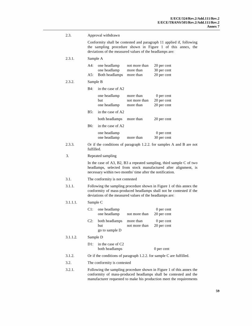
E/ECE/324/Rev.2/Add.111/Rev.2 E/ECE/TRANS/505/Rev.2/Add.111/Rev.2
Annex 7
59
2.3. Approval withdrawn
Conformity shall be contested and paragraph 11 applied if, following the sampling procedure shown in Figure 1 of this annex, the deviations of the measured values of the headlamps are:
2.3.1. Sample A
A4: one headlamp not more than 20 per cent one headlamp more than 30 per cent A5: Both headlamps more than 20 per cent
2.3.2. Sample B
B4: in the case of A2
one headlamp more than 0 per cent but not more than 20 per cent one headlamp more than 20 per cent
B5: in the case of A2
both headlamps more than 20 per cent
B6: in the case of A2
one headlamp 0 per cent one headlamp more than 30 per cent
2.3.3. Or if the conditions of paragraph 1.2.2. for samples A and B are not fulfilled.
3. Repeated sampling
In the case of A3, B2, B3 a repeated sampling, third sample C of two headlamps, selected from stock manufactured after alignment, is necessary within two months' time after the notification.
3.1. The conformity is not contested
3.1.1. Following the sampling procedure shown in Figure 1 of this annex the conformity of mass-produced headlamps shall not be contested if the deviations of the measured values of the headlamps are:
3.1.1.1. Sample C
C1: one headlamp 0 per cent one headlamp not more than 20 per cent
C2: both headlamps more than 0 per cent but not more than 20 per cent go to sample D
3.1.1.2. Sample D
D1: in the case of C2 both headlamps 0 per cent
3.1.2. Or if the conditions of paragraph 1.2.2. for sample C are fulfilled.
3.2. The conformity is contested
3.2.1. Following the sampling procedure shown in Figure 1 of this annex the conformity of mass-produced headlamps shall be contested and the manufacturer requested to make his production meet the requirements

E/ECE/324/Rev.2/Add.111/Rev.2 E/ECE/TRANS/505/Rev.2/Add.111/Rev.2 Annex 7
60
(alignment) if the deviations of the measured values of the headlamps are:
3.2.1.1. Sample D
D2: in the case of C2
one headlamp more than 0 per cent but not more than 20 per cent one headlamp not more than 20 per cent
3.2.1.2. Or if the conditions of paragraph 1.2.2. for sample C are not fulfilled.
3.3. Approval withdrawn
Conformity shall be contested and paragraph 11 applied if, following the sampling procedure shown in Figure 1 of this annex, the deviations of the measured values of the headlamps are:
3.3.1. Sample C
C3: one headlamp not more than 20 per cent one headlamp more than 20 per cent
C4: both headlamps more than 20 per cent
3.3.2. Sample D
D3: in the case of C2
one headlamp 0 or more than 0 per cent one headlamp more than 20 per cent
3.3.3. Or if the conditions of paragraph 1.2.2. for samples C and D are not fulfilled.
4. Change of the vertical position of the cut-off line
With respect to the verification of the change in vertical position of the cut-off line under the influence of heat, the following procedure shall be applied:
One of the headlamps of sample A after sampling procedure in Figure 1 of this annex shall be tested according to the procedure described in paragraph 2.1. of Annex 4 after being subjected three consecutive times to the cycle described in paragraph 2.2.2. of Annex 4.
The headlamp shall be considered as acceptable if ∆r does not exceed 1.5 mrad.
If this value exceeds 1.5 mrad but is not more than 2.0 mrad, the second headlamp of sample A shall be subjected to the test after which the mean of the absolute values recorded on both samples shall not exceed 1.5 mrad.
However, if this value of 1.5 mrad on sample A is not complied with, the two headlamps of sample B shall be subjected to the same procedure and the value of ∆r for each of them shall not exceed 1.5 mrad.
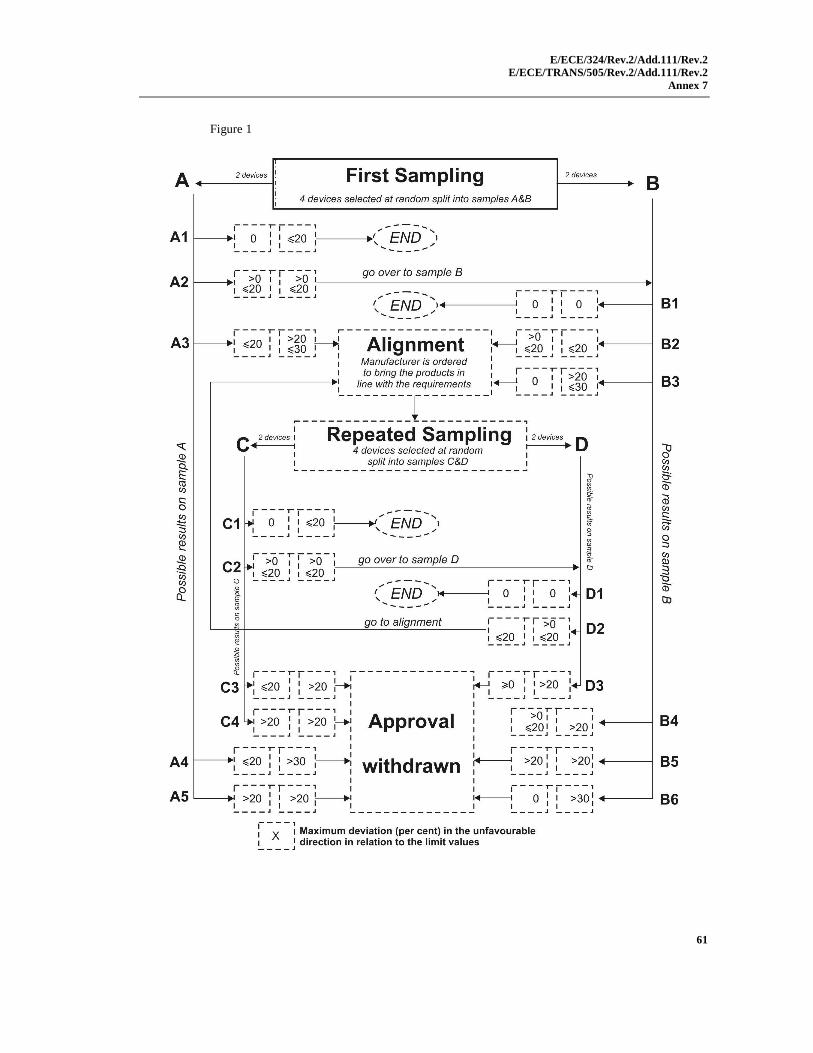
E/ECE/324/Rev.2/Add.111/Rev.2 E/ECE/TRANS/505/Rev.2/Add.111/Rev.2
Annex 7
61
Figure 1

E/ECE/324/Rev.2/Add.111/Rev.2 E/ECE/TRANS/505/Rev.2/Add.111/Rev.2 Annex 8
62
Annex 8
Overview of operational periods concerning tests for stability of photometric performance
Abbreviations: P: passing beam lamp
D: driving beam lamp (D1 + D2 means two driving beams)
F: front fog lamp
− − − − − −: means a cycle of 15 minutes off and 5 minutes lit.
All following grouped headlamps and front fog lamps together with the added class B marking symbols are given as examples and are not exhaustive.
P, D or F 1. P or D or F (HC or HR or B)
0 6 12 h
D P
2. P+D (HCR) or P+D1+D2 (HCR HR) 00 6 12 h
D P
3. P+D (HC/R) or P+D1+D2 (HC/R HR) 0 6 12 h
F P
4. P+F (HC B) 0 6 12 h
F P
5. P+F (HC B/) or HC/B 0 6 12 h
D F
6. D+F (HR B) or D1+D2+F (HR HR B) 0 6 12 h
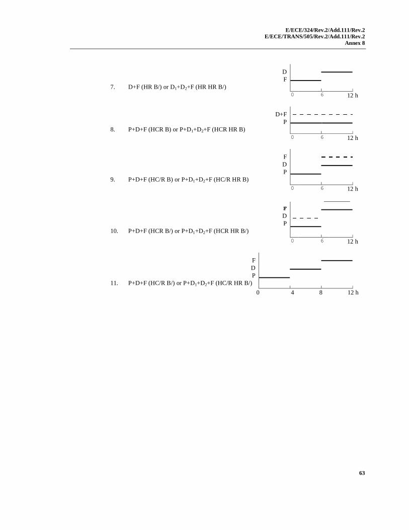
E/ECE/324/Rev.2/Add.111/Rev.2 E/ECE/TRANS/505/Rev.2/Add.111/Rev.2
Annex 8
63
D F
7. D+F (HR B/) or D1+D2+F (HR HR B/) 0 6 12 h
D+F P
8. P+D+F (HCR B) or P+D1+D2+F (HCR HR B) 0 6 12 h
F D P
9. P+D+F (HC/R B) or P+D1+D2+F (HC/R HR B) 0 6 12 h
F
D P
10. P+D+F (HCR B/) or P+D1+D2+F (HCR HR B/) 0 6 12 h
F D P
11. P+D+F (HC/R B/) or P+D1+D2+F (HC/R HR B/) 0 4 8 12 h
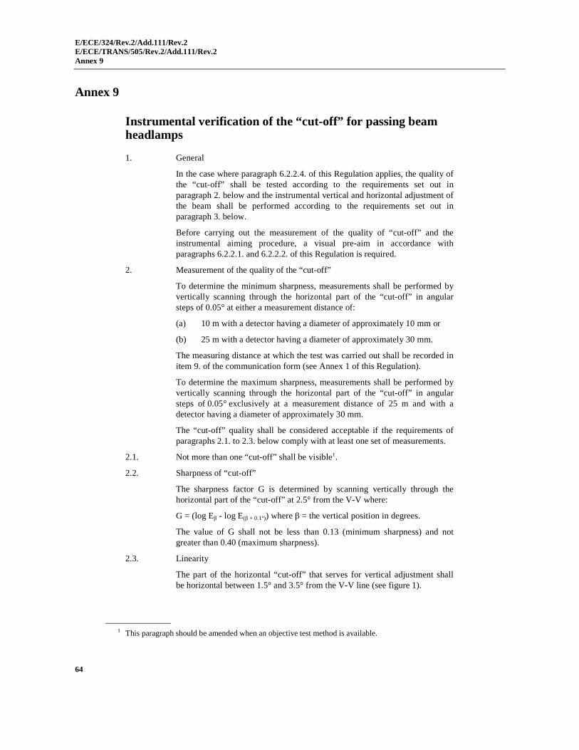
E/ECE/324/Rev.2/Add.111/Rev.2 E/ECE/TRANS/505/Rev.2/Add.111/Rev.2 Annex 9
64
Annex 9
Instrumental verification of the “cut-off” for pa ssing beam headlamps
1. General
In the case where paragraph 6.2.2.4. of this Regulation applies, the quality of the “cut-off” shall be tested according to the requirements set out in paragraph 2. below and the instrumental vertical and horizontal adjustment of the beam shall be performed according to the requirements set out in paragraph 3. below.
Before carrying out the measurement of the quality of “cut-off” and the instrumental aiming procedure, a visual pre-aim in accordance with paragraphs 6.2.2.1. and 6.2.2.2. of this Regulation is required.
2. Measurement of the quality of the “cut-off”
To determine the minimum sharpness, measurements shall be performed by vertically scanning through the horizontal part of the “cut-off” in angular steps of 0.05° at either a measurement distance of:
(a) 10 m with a detector having a diameter of approximately 10 mm or
(b) 25 m with a detector having a diameter of approximately 30 mm.
The measuring distance at which the test was carried out shall be recorded in item 9. of the communication form (see Annex 1 of this Regulation).
To determine the maximum sharpness, measurements shall be performed by vertically scanning through the horizontal part of the “cut-off” in angular steps of 0.05° exclusively at a measurement distance of 25 m and with a detector having a diameter of approximately 30 mm.
The “cut-off” quality shall be considered acceptable if the requirements of paragraphs 2.1. to 2.3. below comply with at least one set of measurements.
2.1. Not more than one “cut-off” shall be visible1.
2.2. Sharpness of “cut-off”
The sharpness factor G is determined by scanning vertically through the horizontal part of the “cut-off” at 2.5° from the V-V where:
G = (log Eβ - log E(β + 0.1°)) where β = the vertical position in degrees.
The value of G shall not be less than 0.13 (minimum sharpness) and not greater than 0.40 (maximum sharpness).
2.3. Linearity
The part of the horizontal “cut-off” that serves for vertical adjustment shall be horizontal between 1.5° and 3.5° from the V-V line (see figure 1).
1 This paragraph should be amended when an objective test method is available.

E/ECE/324/Rev.2/Add.111/Rev.2 E/ECE/TRANS/505/Rev.2/Add.111/Rev.2
Annex 9
65
The inflection points of the “cut-off” gradient at the vertical lines at 1.5°, 2.5° and 3.5° shall be determined by the equation:
The maximum vertical distance between the inflection points determined shall not exceed 0.2°.
(d2 (log E) / dβ2 = 0).
3. Vertical and horizontal adjustment
If the “cut-off” complies with the quality requirements of paragraph 2. of this annex, the beam adjustment may be performed instrumentally.
Figure 1 Measurement of “cut-off” quality
Note: The scales are different for vertical and horizontal lines.
3.1. Vertical adjustment
Moving upward from below the line B (see figure 2 below), a vertical scan is carried out through the horizontal part of the “cut-off” at 2.5° from V-V. The inflection point (where d2 (log E) / dv2 = 0) is determined and positioned on the line B situated one per cent below H-H.
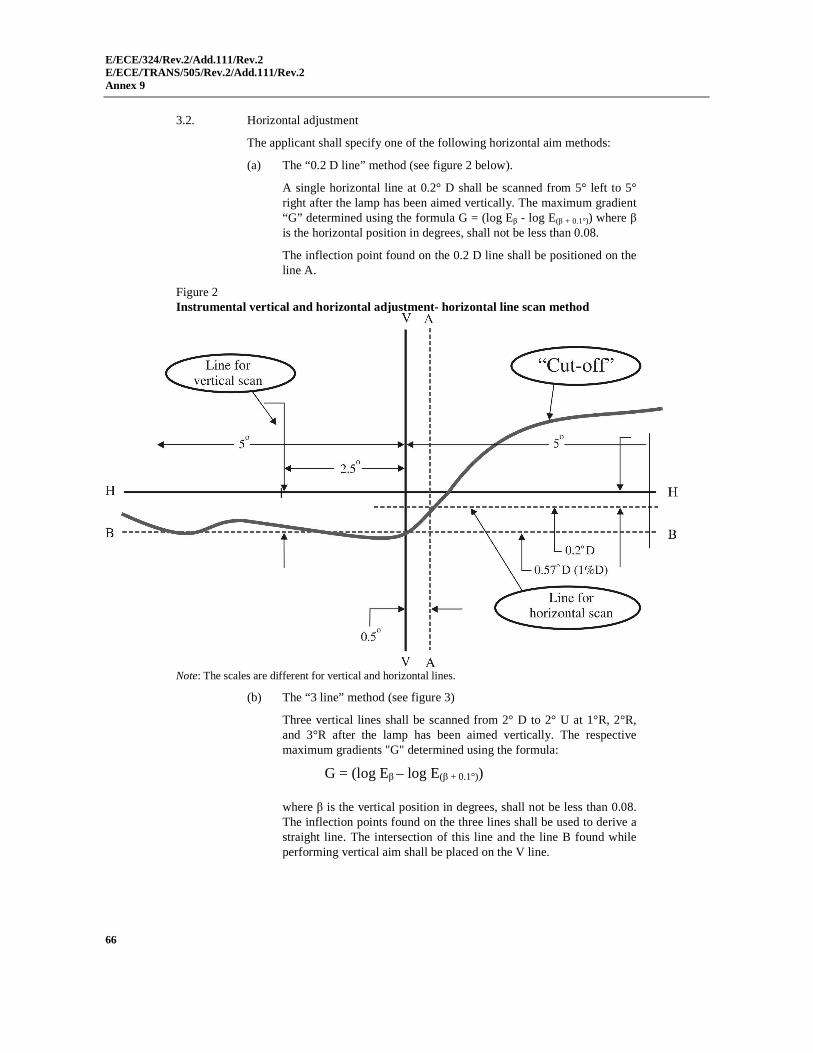
E/ECE/324/Rev.2/Add.111/Rev.2 E/ECE/TRANS/505/Rev.2/Add.111/Rev.2 Annex 9
66
3.2. Horizontal adjustment
The applicant shall specify one of the following horizontal aim methods:
(a) The “0.2 D line” method (see figure 2 below).
A single horizontal line at 0.2° D shall be scanned from 5° left to 5° right after the lamp has been aimed vertically. The maximum gradient “G” determined using the formula G = (log Eβ - log E(β + 0.1°)) where β is the horizontal position in degrees, shall not be less than 0.08.
The inflection point found on the 0.2 D line shall be positioned on the line A.
Figure 2 Instrumental vertical and horizontal adjustment- horizontal line scan method
Note: The scales are different for vertical and horizontal lines.
(b) The “3 line” method (see figure 3)
Three vertical lines shall be scanned from 2° D to 2° U at 1°R, 2°R, and 3°R after the lamp has been aimed vertically. The respective maximum gradients "G" determined using the formula:
G = (log Eβ – log E(β + 0.1°))
where β is the vertical position in degrees, shall not be less than 0.08. The inflection points found on the three lines shall be used to derive a straight line. The intersection of this line and the line B found while performing vertical aim shall be placed on the V line.
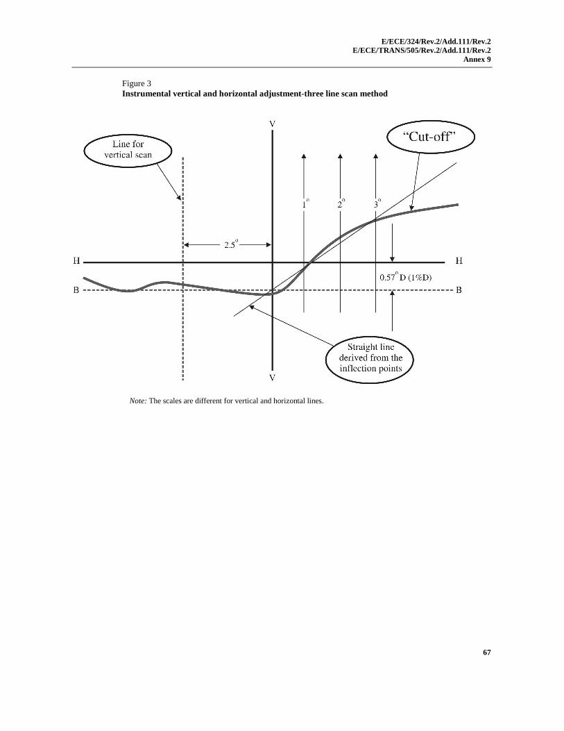
E/ECE/324/Rev.2/Add.111/Rev.2 E/ECE/TRANS/505/Rev.2/Add.111/Rev.2
Annex 9
67
Figure 3 Instrumental vertical and horizontal adjustment-thr ee line scan method
Note: The scales are different for vertical and horizontal lines.

E/ECE/324/Rev.2/Add.111/Rev.2 E/ECE/TRANS/505/Rev.2/Add.111/Rev.2 Annex 10
68
Annex 10
Requirements for LED modules and headlamps including LED modules
1. General specifications
1.1. Each LED module sample submitted shall conform to the relevant specifications of this Regulation when tested with the supplied electronic light source control-gear(s), if any.
1.2. LED module(s) shall be so designed as to be and to remain in good working order when in normal use. They shall moreover exhibit no fault in design or manufacture. A LED module shall be considered to have failed if any one of its LEDs has failed.
1.3. LED module(s) shall be tamperproof.
1.4. The design of removable LED module(s) shall be such that:
1.4.1. When the LED module is removed and replaced by another module provided by the applicant and bearing the same light source module identification code, the photometric specifications of the headlamp shall be met;
1.4.2. LED modules with different light source module identification codes within the same lamp housing, shall not be interchangeable.
2. Manufacture
2.1. The LED(s) on the LED module shall be equipped with suitable fixation elements.
2.2. The fixation elements shall be strong and firmly secured to the LED(s) and the LED module.
3. Test conditions
3.1. Application
3.1.1. All samples shall be tested as specified in paragraph 4. below.
3.1.2. The kind of light sources on a LED module shall be light-emitting diodes (LED) as defined in Regulation No. 48 paragraph 2.7.1. in particular with regard to the element of visible radiation. Other kinds of light sources are not permitted.
3.2. Operating conditions
3.2.1. LED module operating conditions
All samples shall be tested under the conditions as specified in paragraphs 6.1.4. and 6.1.5. of this Regulation. If not specified differently in this annex LED modules shall be tested inside the headlamp as submitted by the manufacturer.
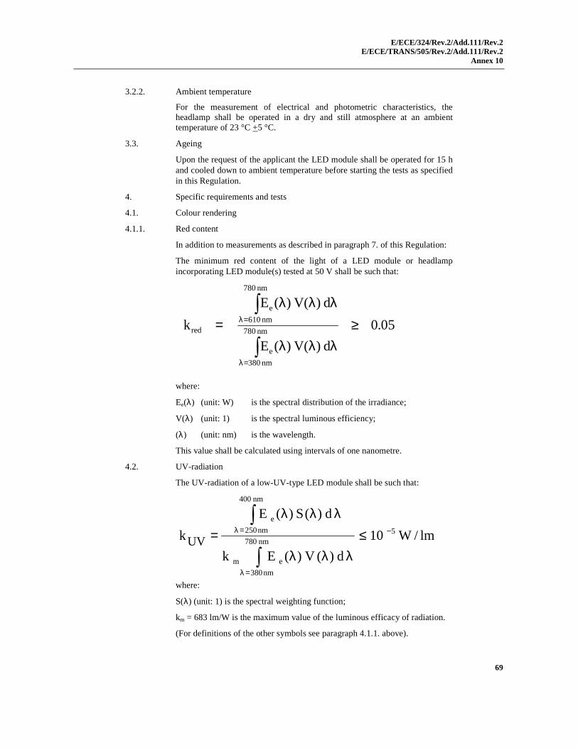
E/ECE/324/Rev.2/Add.111/Rev.2 E/ECE/TRANS/505/Rev.2/Add.111/Rev.2
Annex 10
69
3.2.2. Ambient temperature
For the measurement of electrical and photometric characteristics, the headlamp shall be operated in a dry and still atmosphere at an ambient temperature of 23 °C +5 °C.
3.3. Ageing
Upon the request of the applicant the LED module shall be operated for 15 h and cooled down to ambient temperature before starting the tests as specified in this Regulation.
4. Specific requirements and tests
4.1. Colour rendering
4.1.1. Red content
In addition to measurements as described in paragraph 7. of this Regulation:
The minimum red content of the light of a LED module or headlamp incorporating LED module(s) tested at 50 V shall be such that:
05.0
d)(V)(E
d)(V)(E
k nm780
nm380
e
nm780
nm610
e
red ≥λλλ
λλλ=
∫
∫
=λ
=λ
where:
Ee(λ) (unit: W) is the spectral distribution of the irradiance;
V(λ) (unit: 1) is the spectral luminous efficiency;
(λ) (unit: nm) is the wavelength.
This value shall be calculated using intervals of one nanometre.
4.2. UV-radiation
The UV-radiation of a low-UV-type LED module shall be such that:
lm/W10
d)(V)(Ek
d)(S)(E
k 5nm780
nm380
em
nm400
nm250
e
UV−
=λ
=λ ≤λλλ
λλλ=
∫
∫
where:
S(λ) (unit: 1) is the spectral weighting function;
km = 683 lm/W is the maximum value of the luminous efficacy of radiation.
(For definitions of the other symbols see paragraph 4.1.1. above).

E/ECE/324/Rev.2/Add.111/Rev.2 E/ECE/TRANS/505/Rev.2/Add.111/Rev.2 Annex 10
70
This value shall be calculated using intervals of one nanometer. The UV-radiation shall be weighted according to the values as indicated in the Table UV below:
Table UV Values according to “IRPA/INIRC Guidelines on limits of exposure to ultraviolet radiation”. Wavelengths (in nanometres) chosen are representative; other values should be interpolated.
λ S(λ) λ S(λ) λ S(λ)
250 0.430 305 0.060 355 0.000 16
255 0.520 310 0.015 360 0.000 13
260 0.650 315 0.003 365 0.000 11
265 0.810 320 0.001 370 0.000 09
270 1.000 325 0.000 50 375 0.000 077
275 0.960 330 0.000 41 380 0.000 064
280 0.880 335 0.000 34 385 0.000 530
285 0.770 340 0.000 28 390 0.000 044
290 0.640 345 0.000 24 395 0.000 036
295 0.540 350 0.000 20 400 0.000 030
300 0.300
4.3. Temperature stability
4.3.1. Illuminance
4.3.1.1. A photometric measurement of the headlamp shall be made after 1 minute of operation for the specific function at the test point specified below. For these measurements, the aim can be approximate but must be maintained for before and after ratio measurements.
Test points to be measured:
Passing beam 50 V
Driving beam H – V
4.3.1.2. The lamp shall continue operation until photometric stability has occurred. The moment at which the photometry is stable is defined as the point in time at which the variation of the photometric value is less than 3 per cent within any 15 minutes period. After stability has occurred, aim for complete photometry shall be performed in accordance with the requirements of the specific device. Photometer the lamp at all test points required for the specific device.
4.3.1.3. Calculate the ratio between the photometric test point value determined in paragraph 4.3.1.1. and the point value determined in paragraph 4.3.1.2.
4.3.1.4. Once stability of photometry has been achieved, apply the ratio calculated above to each of the remainder of the test points to create a new photometric table that describes the complete photometry based on one minute of operation.
E/ECE/324/Rev.2/Add.111/Rev.2 E/ECE/TRANS/505/Rev.2/Add.111/Rev.2
Annex 10
71
4.3.1.5. The illuminance values, measured after one minute and after photometric stability has occurred, shall comply with the minimum and maximum requirements.
4.3.2. Colour
The colour of the light emitted measured after one minute and measured after photometric stability has been obtained, as described in paragraph 4.3.1.2. of this annex, shall both be within the required colour boundaries.
5. The measurement of the objective luminous flux of LED module(s) producing the principal passing beam shall be carried out as follows:
5.1. The LED module(s) shall be in the configuration as described in the technical specification as defined in paragraph 2.2.2. of this Regulation. Optical elements (secondary optics) shall be removed by the Technical Service at the request of the applicant by the use of tools. This procedure and the conditions during the measurements as described below shall be described in the test report.
5.2. Three LED modules of each type shall be submitted by the applicant with the light source control gear, if applicable, and sufficient instructions.
Suitable thermal management (e.g. heat sink) may be provided, to simulate similar thermal conditions as in the corresponding headlamp application.
Before the test each LED module shall be aged at least for seventy-two hours under the same conditions as in the corresponding headlamp application.
In the case of use of an integrating sphere, the sphere shall have a minimum diameter of one meter, and at least ten times the maximum dimension of the LED module, whichever is the largest. The flux measurements can also be performed by integration using a goniophotometer. The prescriptions in CIE - Publication 84 - 1989, regarding the room temperature, positioning, etc., shall be taken into consideration.
The LED module shall be burned in for approximately one hour in the closed sphere or goniophotometer.
The flux shall be measured after stability has occurred, as explained in paragraph 4.3.1.2. of Annex 10 to this Regulation.
The average of the measurements of the three samples of each type of LED module shall be deemed to be its objective luminous flux.
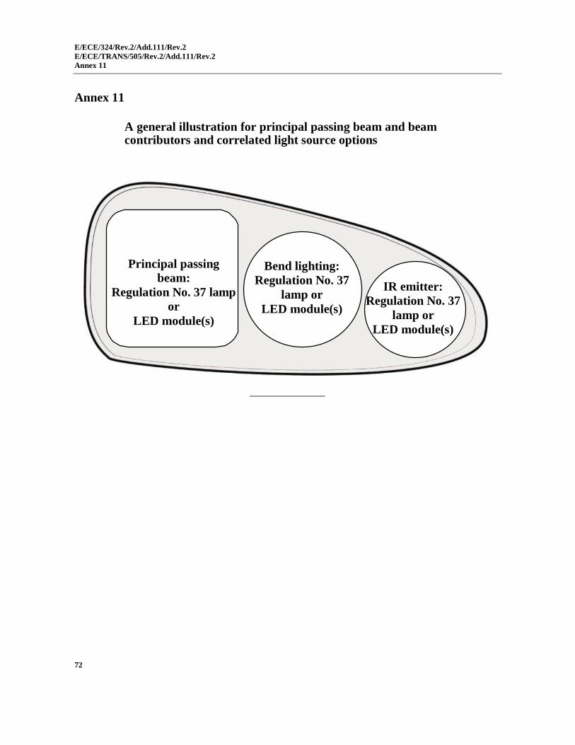
E/ECE/324/Rev.2/Add.111/Rev.2 E/ECE/TRANS/505/Rev.2/Add.111/Rev.2 Annex 11
72
Annex 11
A general illustration for principal passing beam and beam contributors and correlated light source options
Principal passing beam:
Regulation No. 37 lamp or
LED module(s)
Bend lighting: Regulation No. 37
lamp or LED module(s)
IR emitter: Regulation No. 37
lamp or LED module(s)