
Agilent Technologies System DC Power Supply - RITridl.cfd.rit.edu/products/manuals/Agilent/power...
131
A A A A Agilent Technologies System DC Power Supply Series N5700 User’s Guide
Transcript of Agilent Technologies System DC Power Supply - RITridl.cfd.rit.edu/products/manuals/Agilent/power...
A A A A
Agilent Technologies System DC Power Supply Series N5700
User’s Guide

2 Series N5700 User’s Guide
Legal Notices © Agilent Technologies, Inc. 2004, 2005 No part of this document may be photocopied, reproduced, or translated to another language without the prior agreement and written consent of Agilent Technologies, Inc. as governed by United States and international copyright laws.
Warranty The material contained in this document is provided “as is,” and is subject to being changed, without notice, in future editions. Further, to the maximum extent permitted by applicable law, Agilent disclaims all warranties, either express or implied, with regard to this manual and any information contained herein, including but not limited to the implied warranties of merchantability and fitness for a particular purpose. Agilent shall not be liable for errors or for incidental or consequential damages in connection with the furnishing, use, or performance of this document or of any information contained herein. Should Agilent and the user have a separate written agreement with warranty terms covering the material in this document that conflict with these terms, the warranty terms in the separate agreement shall control.
Manual Editions Manual Part Number: 5969-2917 Edition 3, January, 2005 Printed in Malaysia. Reprints of this manual containing minor corrections and updates may have the same printing date. Revised editions are identified by a new printing date.
Certification Agilent Technologies certifies that this product met its published specifications at time of shipment from the factory. Agilent Technologies further certifies that its calibration measurements are traceable to the United States National Institute of Standards and Technology, to the extent allowed by the Institute's calibration facility, and to the calibration facilities of other International Standards Organization members.
Exclusive Remedies THE REMEDIES PROVIDED HEREIN ARE THE CUSTOMER'S SOLE AND EXCLUSIVE REMEDIES. AGILENT TECHNOLOGIES SHALL NOT BE LIABLE FOR ANY DIRECT, INDIRECT, SPECIAL, INCIDENTAL, OR CONSEQUENTIAL DAMAGES, WHETHER BASED ON CONTRACT, TORT, OR ANY OTHER LEGAL THEORY.
Assistance This product comes with the standard product warranty. Warranty options, extended support contacts, product maintenance agreements and customer assistance agreements are also available. Contact your nearest Agilent Technologies Sales and Service office for further information on Agilent Technologies' full line of Support Programs.
Technologies Licenses The hardware and or software described in this document are furnished under a license and may be used or copied only in accordance with the terms of such license.
Restricted Rights Legend Software and technical data rights granted to the federal government include only those rights customarily provided to end user customers. Agilent provides this customary commercial license in Software and technical data pursuant to FAR 12.211 (Technical Data) and 12.212 (Computer Software) and, for the Department of Defense, DFARS 252.227-7015 (Technical Data – Commercial Items) and DFARS 227.7202-3 (Rights in Commercial Computer Software or Computer Software Documentation).
Trademarks Microsoft and Windows are U.S. registered trademarks of Microsoft Corporation.
Series N5700 User’s Guide 3
Safety Notices The following general safety precautions must be observed during all phases of operation of this instrument. Failure to comply with these precautions or with specific warnings or instructions elsewhere in this manual violates safety standards of design, manufacture, and intended use of the instrument. Agilent Technologies assumes no liability for the customer's failure to comply with these requirements.
General Do not use this product in any manner not specified by the manufacturer. The protective features of this product may be impaired if it is used in a manner not specified in the operation instructions.
Before Applying Power Verify that all safety precautions are taken. Make all connections to the unit before applying power. Note the instrument's external markings described under "Safety Symbols"
Ground the Instrument This product is a Safety Class 1 instrument (provided with a protective earth terminal). To minimize shock hazard, the instrument chassis and cover must be connected to an electrical ground. The instrument must be connected to the ac power mains through a grounded power cable, with the ground wire firmly connected to an electrical ground (safety ground) at the power outlet. Any interruption of the protective (grounding) conductor or disconnection of the protective earth terminal will cause a potential shock hazard that could result in personal injury.
Fuses The instrument contains an internal fuse, which is not customer accessible.
Do Not Operate in an Explosive Atmosphere Do not operate the instrument in the presence of flammable gases or fumes.
Do Not Remove the Instrument Cover Only qualified, service-trained personnel who are aware of the hazards involved should remove instrument covers. Always disconnect the power cable and any external circuits before removing the instrument cover.
Do Not Modify the Instrument Do not install substitute parts or perform any unauthorized modification to the product. Return the product to an Agilent Sales and Service Office for service and repair to ensure that safety features are maintained.
In Case of Damage Instruments that appear damaged or defective should be made inoperative and secured against unintended operation until they can be repaired by qualified service personnel
A CAUTION notice denotes a hazard. It calls attention to an operating procedure, practice, or the like that, if not correctly performed or adhered to, could result in damage to the product or loss of important data. Do not proceed beyond a CAUTION notice until the indicated conditions are fully understood and met.
A WARNING notice denotes a hazard. It calls attention to an operating procedure, practice, or the like that, if not correctly performed or adhered to, could result in personal injury or death. Do not proceed beyond a WARNING notice until the indicated conditions are fully understood and met.
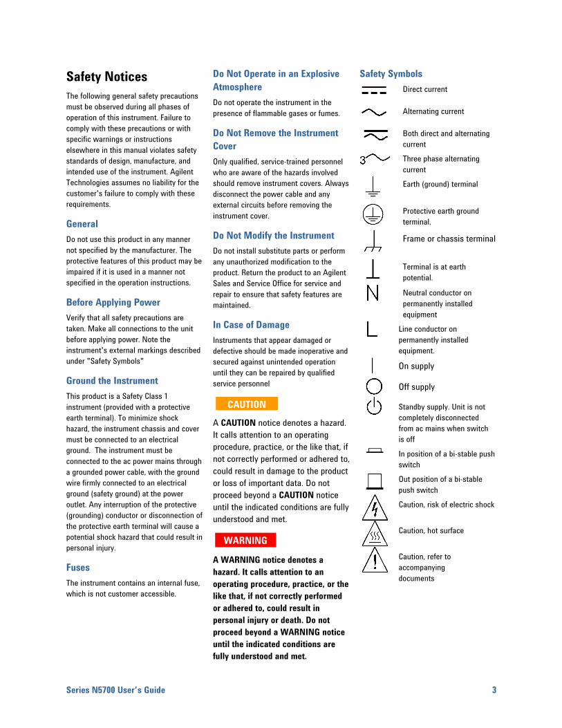
Safety Symbols
Direct current
Alternating current
Both direct and alternating current
Three phase alternating current
Earth (ground) terminal
Protective earth ground terminal.
Frame or chassis terminal
Terminal is at earth potential.
Neutral conductor on permanently installed equipment
Line conductor on permanently installed equipment.
On supply
Off supply
Standby supply. Unit is not completely disconnected from ac mains when switch is off In position of a bi-stable push switch Out position of a bi-stable push switch
Caution, risk of electric shock
Caution, hot surface
Caution, refer to accompanying documents
CAUTION
WARNING
4 Series N5700 User’s Guide
In this Book This User’s Manual contains the operating instructions, installation instructions, and specifications of the Agilent Technologies Series N5700 750W and 1500W System DC Power Supplies. Specific chapters in this manual contain the following information:
Quick Reference – Chapter 1 is a quick reference section that helps you quickly become familiar with your Agilent N5700 power supply.
Installation – Chapter 2 describes how to install your power supply. It describes how to connect various loads to the output. It discusses remote sensing as well as parallel and series operation.
Operating the Power Supply Locally – Chapter 3 describes how to operate the power supply from the front panel and from the analog connector on the rear panel. It also includes a turn-on check-out procedure to verify the unit is operating properly.
Operating the Power Supply Remotely – Chapter 4 describes how to configure the remote interfaces. It also gives a brief overview of the SCPI command structure and basic programming concepts.
Language Reference – Chapter 5 describes all of the SCPI programming commands.
Programming Examples – Chapter 6 provides Visual BASIC example programs that illustrate some common applications.
Specifications – Appendix A describes specifications and supplemental characteristics.
Verification and Calibration Procedures – Appendix B explains the verification and calibration procedures.
Service – Appendix C describes what to do if your unit requires service.
Compatibility – Appendix D documents the compatibility commands of the Agilent 603xA power supplies that are supported by the Agilent N5700 power supplies.
NOTE You can contact Agilent Technologies at one of the following telephone numbers for warranty, service, or technical support information. In the United States: (800) 829-4444 In Europe: 31 20 547 2111 In Japan: 0120-421-345 Or use our Web link for information on contacting Agilent in your country or specific location: www.agilent.com/find/assist Or contact your Agilent Technologies Representative.
The web contains the most up to date version of the manual. Go to http://www.agilent.com/find/N5700 to get the latest version of the manual.

Series N5700 User’s Guide
Contents
1 Quick Reference The Agilent N5700 DC Power Supplies – At a Glance ................................. 8 The Front Panel - At a Glance......................................................................... 10 The Rear Panel – At a Glance......................................................................... 12
2 Installation General Information.......................................................................................... 16 Inspecting the Unit ........................................................................................... 17 Installing the Unit.............................................................................................. 17 Connecting the Line Cord ................................................................................ 19 Connecting the Load......................................................................................... 21 Output Voltage Sensing ................................................................................... 24 Load Considerations ......................................................................................... 26 Parallel Connections......................................................................................... 28 Series Connections........................................................................................... 30 J1 Connector Connections .............................................................................. 32
3 Operating the Power Supply Locally Turn-On Check-Out ........................................................................................... 34 Normal Operation.............................................................................................. 36 Protection Functions ........................................................................................ 37 Output On/Off Controls.................................................................................... 40 Analog Programming of Output Voltage and Current................................. 42
4 Operating the Power Supply Remotely Connecting to the Interfaces .......................................................................... 48 SCPI Commands – an Introduction................................................................ 58
5 Language Reference SCPI Command Summary................................................................................ 64 Calibration Commands ..................................................................................... 66 Measure Commands......................................................................................... 67 Output Commands ............................................................................................ 68 Source Commands............................................................................................ 69 Status Commands............................................................................................. 71 System Commands ........................................................................................... 77
5
Trigger Commands............................................................................................ 79

6 Series N5700 User’s Guide
6 Programming Examples Output Programming Example ........................................................................ 82 Trigger Programming Example........................................................................ 84
Appendix A Specifications Performance Specifications ............................................................................ 88 Supplemental Characteristics ......................................................................... 89 Outline Diagram................................................................................................. 91
Appendix B Verification and Calibration Verification ......................................................................................................... 94 Calibration ........................................................................................................113
Appendix C Service Types of Service Available.............................................................................116 Repackaging for Shipment.............................................................................116 Operating Checklist.........................................................................................116 Error Messages ...............................................................................................118
Appendix D Compatibility Differences – In General ................................................................................124 Compatibility Command Summary ...............................................................125
Index ...........................................................................................................................................................127
Series N5700 User’s Guide 7
1 Quick Reference The Agilent N5700 DC Power Supplies – At a Glance ................................. 8 The Front Panel - At a Glance......................................................................... 10 The Rear Panel – At a Glance......................................................................... 12
This chapter concisely describes the Agilent Technologies Series N5700 Power Supplies.
This chapter is not meant to describe every operating feature in detail. It is simply a quick reference guide to quickly become familiar with the essential components of the power supply. It can also be used as a memory jogger for experienced users to quickly find a front/rear panel function.
A quick reference programming command chart is included in the beginning of chapter 5.
1 Quick Reference
8 Series N5700 User’s Guide
The Agilent N5700 DC Power Supplies – At a Glance The Agilent Technologies Series N5700 System DC Power Supplies are general-purpose, 1U (rack unit) high, switching power supplies that are available with a wide variety of output voltage and current ratings.
These power supplies are power-factor corrected and operate from a worldwide AC voltage range. Output voltage and current are continuously displayed and LED indicators show the complete operating status of the power supply.
The front panel controls allow the user to set the output parameters, over-voltage, under-voltage, and over-current protection levels, and preview the settings.
The rear panel includes the necessary connectors to control and monitor the power supply operation by analog signals or by the built-in remote communication interfaces.
Output Features • Constant voltage/constant current with automatic crossover.
• High-resolution voltage and current front panel controls.
• Accurate voltage and current readback.
• Independent edge-triggered external shut-off, and level-triggered external enable/disable.
• Parallel master/slave operation with active current sharing.
• Remote sensing to compensate for voltage drop in load leads.
• Analog output programming and monitoring.
System Features • Built-in GBIB/LAN/USB interface.
• A built-in Web server that lets you control the instrument directly from an internet browser on your computer.
• Zero-gap stacking - no ventilation holes at the top and bottom surface of the power supply.
• Universal input voltage with active power factor correction.
• Fan speed control for low noise and extended fan life.
Quick Reference 1
Series N5700 User’s Guide 9
Programmable Functions • Output voltage and current setting.
• Output voltage and current measurement.
• Output voltage and current trigger setting.
• Output On/Off control.
• Over-current protection setting.
• Over-voltage protection setting and readback.
• Under-voltage limit setting and readback.
• Start-up mode (either last setting or reset mode)
• Status register setting and readback.
• Bus trigger
• Calibration
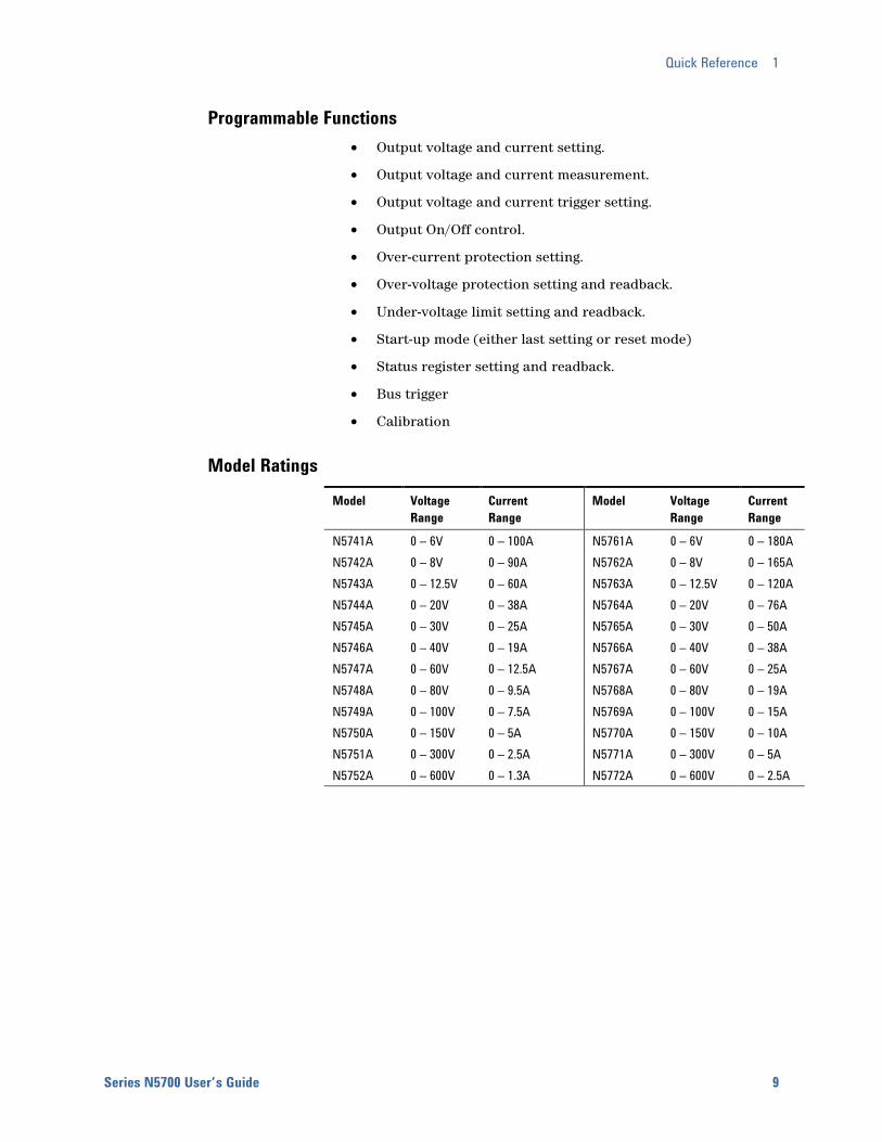
Model Ratings Model Voltage
Range Current Range
Model Voltage Range
Current Range
N5741A 0 – 6V 0 – 100A N5761A 0 – 6V 0 – 180A N5742A 0 – 8V 0 – 90A N5762A 0 – 8V 0 – 165A N5743A 0 – 12.5V 0 – 60A N5763A 0 – 12.5V 0 – 120A N5744A 0 – 20V 0 – 38A N5764A 0 – 20V 0 – 76A N5745A 0 – 30V 0 – 25A N5765A 0 – 30V 0 – 50A N5746A 0 – 40V 0 – 19A N5766A 0 – 40V 0 – 38A N5747A 0 – 60V 0 – 12.5A N5767A 0 – 60V 0 – 25A N5748A 0 – 80V 0 – 9.5A N5768A 0 – 80V 0 – 19A N5749A 0 – 100V 0 – 7.5A N5769A 0 – 100V 0 – 15A N5750A 0 – 150V 0 – 5A N5770A 0 – 150V 0 – 10A N5751A 0 – 300V 0 – 2.5A N5771A 0 – 300V 0 – 5A N5752A 0 – 600V 0 – 1.3A N5772A 0 – 600V 0 – 2.5A
1 Quick Reference
10 Series N5700 User’s Guide
The Front Panel - At a Glance
VOLTAGE
PROT FINE LIMIT/OVPUVL OCP REM OUT ON
DC AMPS CURRENTDC VOLTS
POWER
1
14
1718
19
2
15
16
3
13
10
4
11
5
12
9
6
7
8
CV CC
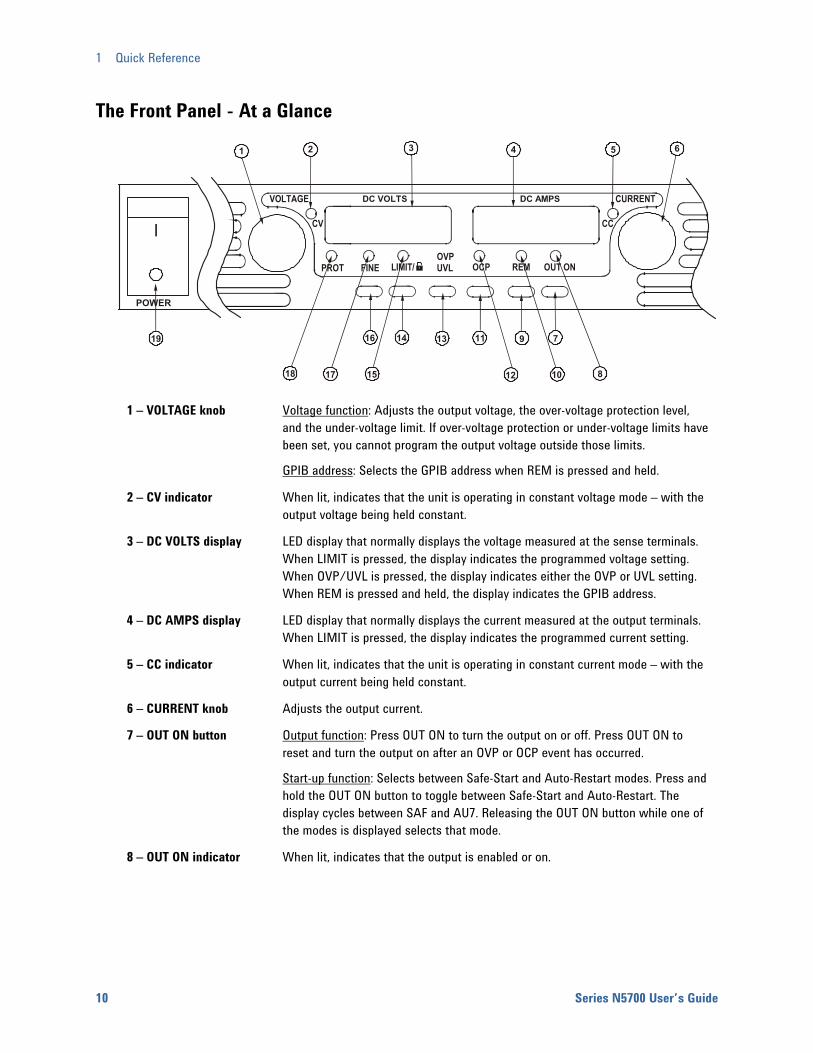
1 – VOLTAGE knob Voltage function: Adjusts the output voltage, the over-voltage protection level, and the under-voltage limit. If over-voltage protection or under-voltage limits have been set, you cannot program the output voltage outside those limits.
GPIB address: Selects the GPIB address when REM is pressed and held.
2 – CV indicator When lit, indicates that the unit is operating in constant voltage mode – with the output voltage being held constant.
3 – DC VOLTS display LED display that normally displays the voltage measured at the sense terminals. When LIMIT is pressed, the display indicates the programmed voltage setting. When OVP/UVL is pressed, the display indicates either the OVP or UVL setting. When REM is pressed and held, the display indicates the GPIB address.
4 – DC AMPS display LED display that normally displays the current measured at the output terminals. When LIMIT is pressed, the display indicates the programmed current setting.
5 – CC indicator When lit, indicates that the unit is operating in constant current mode – with the output current being held constant.
6 – CURRENT knob Adjusts the output current.
7 – OUT ON button Output function: Press OUT ON to turn the output on or off. Press OUT ON to reset and turn the output on after an OVP or OCP event has occurred.
Start-up function: Selects between Safe-Start and Auto-Restart modes. Press and hold the OUT ON button to toggle between Safe-Start and Auto-Restart. The display cycles between SAF and AU7. Releasing the OUT ON button while one of the modes is displayed selects that mode.
8 – OUT ON indicator When lit, indicates that the output is enabled or on.
Quick Reference 1
Series N5700 User’s Guide 11
9 – REM button Mode function: Press REM to put the unit into local mode. (This button can be disabled with a Local Lockout command).
Address function: Selects the GPIB address. Press and hold the REM button for three seconds to set the address with the Voltage knob.
10 – REM indicator When lit, indicates that the unit is in Remote mode.
11 – OCP button Enable function: Press OCP to turn over-current protection on. Press OCP again to turn over-current protection off.
Reset OCP: When an over-current protection event occurs, press the OUT ON button to enable the output and re-arm over-current protection.
12 – OCP indicator When lit, indicates that over-current protection is enabled or on.
13 – OVP/UVL button OVP function: Press OVP/UVL once to set the over-voltage protection level with the Voltage knob (the display shows OUP). You cannot set the over-voltage protection lower than about 5% above the present output voltage setting.
UVL function: Press OVP/UVL twice to set the under-voltage programming limit with the Voltage knob (the display shows UUL). You cannot set the under-voltage protection higher than about 5% below the present output voltage setting.
14 – LIMIT button Limit function: Press LIMIT to display the output voltage and current limit. For five seconds the display shows the settings and then it returns to show the actual output voltage and current.
Lock function: Press and hold the LIMIT button to toggle between Locked front panel and Unlocked front panel. The display will cycle between LFP and UFP. Releasing the LIMIT button while one of the modes is displayed selects that mode.
15 – LIMIT indicator When lit, indicates that the LIMIT button is pressed.
16 – FINE button Selects Fine or Coarse adjustment control. In Fine mode, the Voltage and Current knobs operate with high resolution; in Coarse mode, with lower resolution (approximately six turns).
17 – FINE indicator When lit, indicates that the unit is in Fine adjustment mode.
18 – PROT indicator When blinking, indicates that a fault has occurred. OVP, OCP, OTP, Enable fail, and AC fail detection will cause the PROT indicator to blink. The PROT indicator may blink and the display indicate AC for a few seconds after the unit is turned off because of residual energy inside the unit.
19 – POWER switch Turns the power supply on or off.
1 Quick Reference
12 Series N5700 User’s Guide
The Rear Panel – At a Glance 9
57 3
8
4612
750W
1500W6V - 60V
80V - 600VAC INPUT
ON
OFF
+V -V
NOT ACTIVE
J2 SW1GPIB
ANALOG PROGRAMMING+S+LS NC -LC-S 1 2 3 4 5 6 7 8 9
10/100 EthernetLINK TX
J1
! !
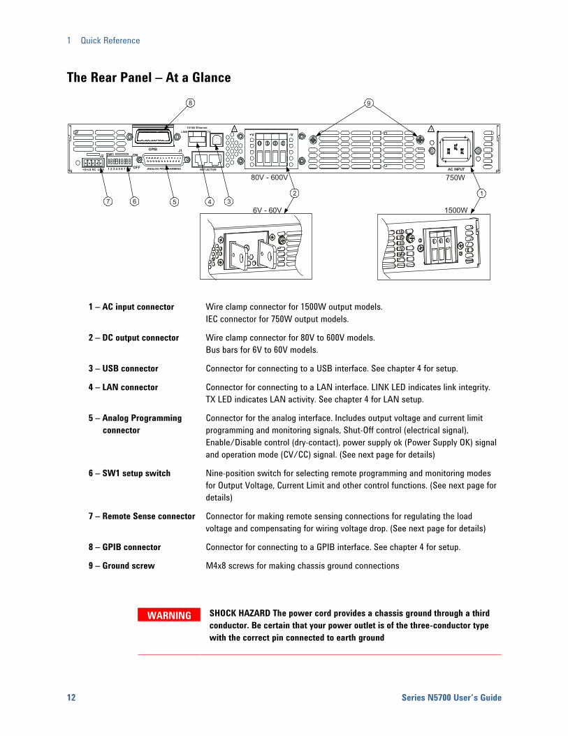
1 – AC input connector Wire clamp connector for 1500W output models.
IEC connector for 750W output models.
2 – DC output connector Wire clamp connector for 80V to 600V models. Bus bars for 6V to 60V models.
3 – USB connector Connector for connecting to a USB interface. See chapter 4 for setup.
4 – LAN connector Connector for connecting to a LAN interface. LINK LED indicates link integrity. TX LED indicates LAN activity. See chapter 4 for LAN setup.
5 – Analog Programming connector
Connector for the analog interface. Includes output voltage and current limit programming and monitoring signals, Shut-Off control (electrical signal), Enable/Disable control (dry-contact), power supply ok (Power Supply OK) signal and operation mode (CV/CC) signal. (See next page for details)
6 – SW1 setup switch Nine-position switch for selecting remote programming and monitoring modes for Output Voltage, Current Limit and other control functions. (See next page for details)
7 – Remote Sense connector Connector for making remote sensing connections for regulating the load voltage and compensating for wiring voltage drop. (See next page for details)
8 – GPIB connector Connector for connecting to a GPIB interface. See chapter 4 for setup.
9 – Ground screw M4x8 screws for making chassis ground connections
WARNING SHOCK HAZARD The power cord provides a chassis ground through a third conductor. Be certain that your power outlet is of the three-conductor type with the correct pin connected to earth ground

Quick Reference 1
Series N5700 User’s Guide 13
J2 Sense Connector 1 – Remote sense (+) 2 – Local sense (+) 3 – Not used 4 – Local sense (–) 5 – Remote sense (–)
The factory-shipped configuration is shown in the figure.
SW1 Setup Switch
The factory-shipped setting is Down for all switches.
1 – Output voltage, voltage programming
Down: The output voltage is programmed by the front panel. Up: The output voltage is programmed by the external voltage signal.
2 – Output current, voltage programming
Down: The output current is programmed by the front panel. Up: The output current is programmed by the external voltage signal.
3 – Programming range (voltage/resistance)
Down: The remote programming range is: 0 – 5V / 0 – 5KΩ. Up: The remote programming range is: 0 – 10V / 0 – 10KΩ.
4 – Voltage and Current monitoring range
Down: The remote monitoring range is: 0 – 5V. Up: The remote programming range is: 0 – 10V.
5 – Shut-Off Logic Select Down: OUT OFF = Low (0 – 0.6V) or short; OUT ON = High (2V – 15V) or open. Up: OUT OFF = High (2V – 15V) or open; OUT ON = Low (0 – 0.6V) or short.
6 – Not Used
7 – Output voltage, resistive programming
Down: The output voltage is programmed by the front panel. Up: The output voltage is programmed by the external resistor.
8 – Output current, resistive programming
Down: The output current is programmed by the front panel. Up: The output current is programmed by the external resistor.
9 – Enable/Disable control Down: The J1 Enable+/Enable– pins are not active. Up: The J1 Enable+/Enable– pins are active.
1 2 3 4 5 6 78 9
1 Quick Reference
14 Series N5700 User’s Guide
J1 Analog Programming Connector
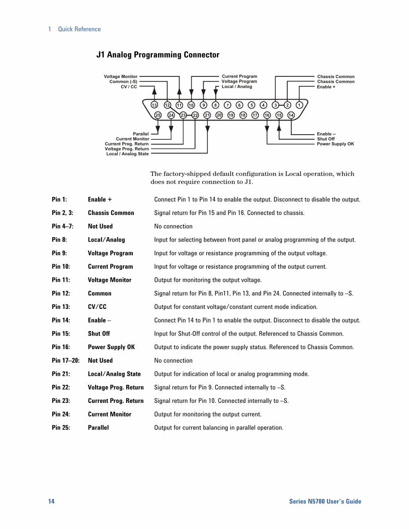
The factory-shipped default configuration is Local operation, which does not require connection to J1.
Pin 1: Enable + Connect Pin 1 to Pin 14 to enable the output. Disconnect to disable the output.
Pin 2, 3: Chassis Common Signal return for Pin 15 and Pin 16. Connected to chassis.
Pin 4–7: Not Used No connection
Pin 8: Local/Analog Input for selecting between front panel or analog programming of the output.
Pin 9: Voltage Program Input for voltage or resistance programming of the output voltage.
Pin 10: Current Program Input for voltage or resistance programming of the output current.
Pin 11: Voltage Monitor Output for monitoring the output voltage.
Pin 12: Common Signal return for Pin 8, Pin11, Pin 13, and Pin 24. Connected internally to –S.
Pin 13: CV/CC Output for constant voltage/constant current mode indication.
Pin 14: Enable – Connect Pin 14 to Pin 1 to enable the output. Disconnect to disable the output.
Pin 15: Shut Off Input for Shut-Off control of the output. Referenced to Chassis Common.
Pin 16: Power Supply OK Output to indicate the power supply status. Referenced to Chassis Common.
Pin 17–20: Not Used No connection
Pin 21: Local/Analog State Output for indication of local or analog programming mode.
Pin 22: Voltage Prog. Return Signal return for Pin 9. Connected internally to –S.
Pin 23: Current Prog. Return Signal return for Pin 10. Connected internally to –S.
Pin 24: Current Monitor Output for monitoring the output current.
Pin 25: Parallel Output for current balancing in parallel operation.
141516171819202122232425
1234567810111213 9
Current MonitorCurrent Prog. ReturnVoltage Prog. ReturnLocal / Analog State
Chassis Common
Enable +
Voltage MonitorCommon (-S)
CV / CC
Current ProgramVoltage ProgramLocal / Analog
Parallel Enable --Shut OffPower Supply OK
Chassis Common
Series N5700 User’s Guide
2 Installation General Information.......................................................................................... 16 Inspecting the Unit ........................................................................................... 17 Installing the Unit.............................................................................................. 17 Connecting the Line Cord ................................................................................ 19 Connecting the Load......................................................................................... 21 Output Voltage Sensing ................................................................................... 24 Load Considerations ......................................................................................... 26 Parallel Connections......................................................................................... 28 Series Connections........................................................................................... 30 J1 Connector Connections .............................................................................. 32
This chapter describes how to install your power supply. It discusses installation, rack mounting, and line cord connections.
This chapter also discusses how to connect your load to the output terminals. It discusses what you need to know about wire sizes and how to compensate for voltage drops in the load leads. It also discusses various loads configurations and how to connect units in series and parallel.
Before getting started, check the list under “Items Supplied” and verify that you have received these items with your instrument. If anything is missing, please contact your nearest Agilent Sales and Service Office.
15
2 Installation
16 Series N5700 User’s Guide
General Information
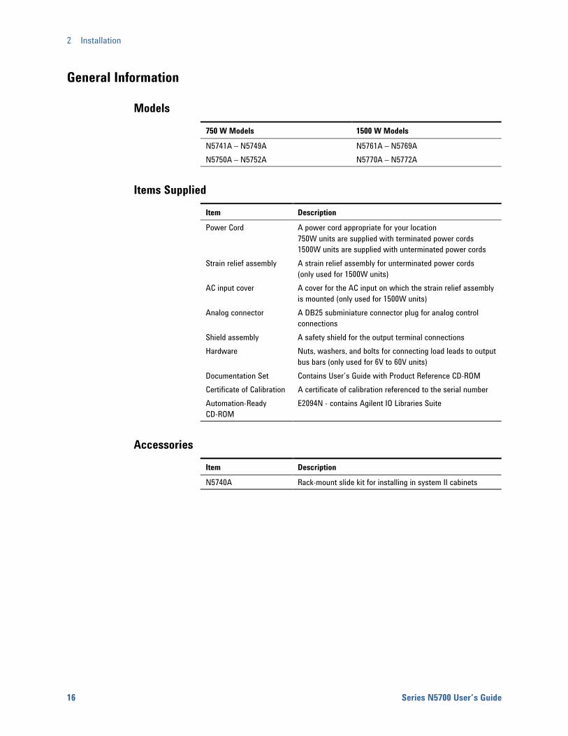
Models 750 W Models 1500 W Models
N5741A – N5749A N5761A – N5769A N5750A – N5752A N5770A – N5772A
Items Supplied Item Description
Power Cord A power cord appropriate for your location 750W units are supplied with terminated power cords 1500W units are supplied with unterminated power cords
Strain relief assembly A strain relief assembly for unterminated power cords (only used for 1500W units)
AC input cover A cover for the AC input on which the strain relief assembly is mounted (only used for 1500W units)
Analog connector A DB25 subminiature connector plug for analog control connections
Shield assembly A safety shield for the output terminal connections Hardware Nuts, washers, and bolts for connecting load leads to output
bus bars (only used for 6V to 60V units) Documentation Set Contains User’s Guide with Product Reference CD-ROM Certificate of Calibration A certificate of calibration referenced to the serial number Automation-Ready CD-ROM
E2094N - contains Agilent IO Libraries Suite
Accessories Item Description
N5740A Rack-mount slide kit for installing in system II cabinets
Installation 2
Series N5700 User’s Guide 17
Inspecting the Unit When you receive your power supply, inspect it for any obvious damage that may have occurred during shipment. If there is damage, notify the shipping carrier and nearest Agilent Sales and Service Office immediately. Refer to Appendix C for more information.
Until you have checked out the power supply, save the shipping carton and packing materials in case the unit has to be returned.
Installing the Unit
Safety Considerations This power supply is a Safety Class 1 instrument, which means it has a protective earth terminal. That terminal must be connected to earth ground through power source equipped with a ground receptacle. Refer to the Safety Summary page at the beginning of this guide for general safety information. Before installation or operation, check the power supply and review this guide for safety warnings and instructions. Safety warnings for specific procedures are located at appropriate places throughout this Guide.
Environment
WARNING Do not operate the instrument in the presence of flammable gasses or fumes
The environmental conditions, dimensions of the instrument, as well as an outline diagram are given in Appendix A. Basically, the instrument should only be operated indoors in a controlled environment. Do not operate the power supply in an area where the ambient temperature exceeds 40° C.
NOTE Agilent N5700 power supplies generate magnetic fields, which may affect the operation of other instruments. If your equipment is susceptible to magnetic fields, do not position it adjacent to the power supply.
Airflow Fans cool the power supply by drawing air through the front and exhausting it out the back. The instrument must be installed in a location that allows sufficient space of at least 10 cm (4 in) at the front and back of the unit for adequate air circulation.
2 Installation
18 Series N5700 User’s Guide
Rack Installation
CAUTION Ensure that the screws used to attach the rack slide kit do not penetrate more than 6 mm into the sides of the unit.
Do not block the air intake at the front, or the exhaust at the rear of the unit.
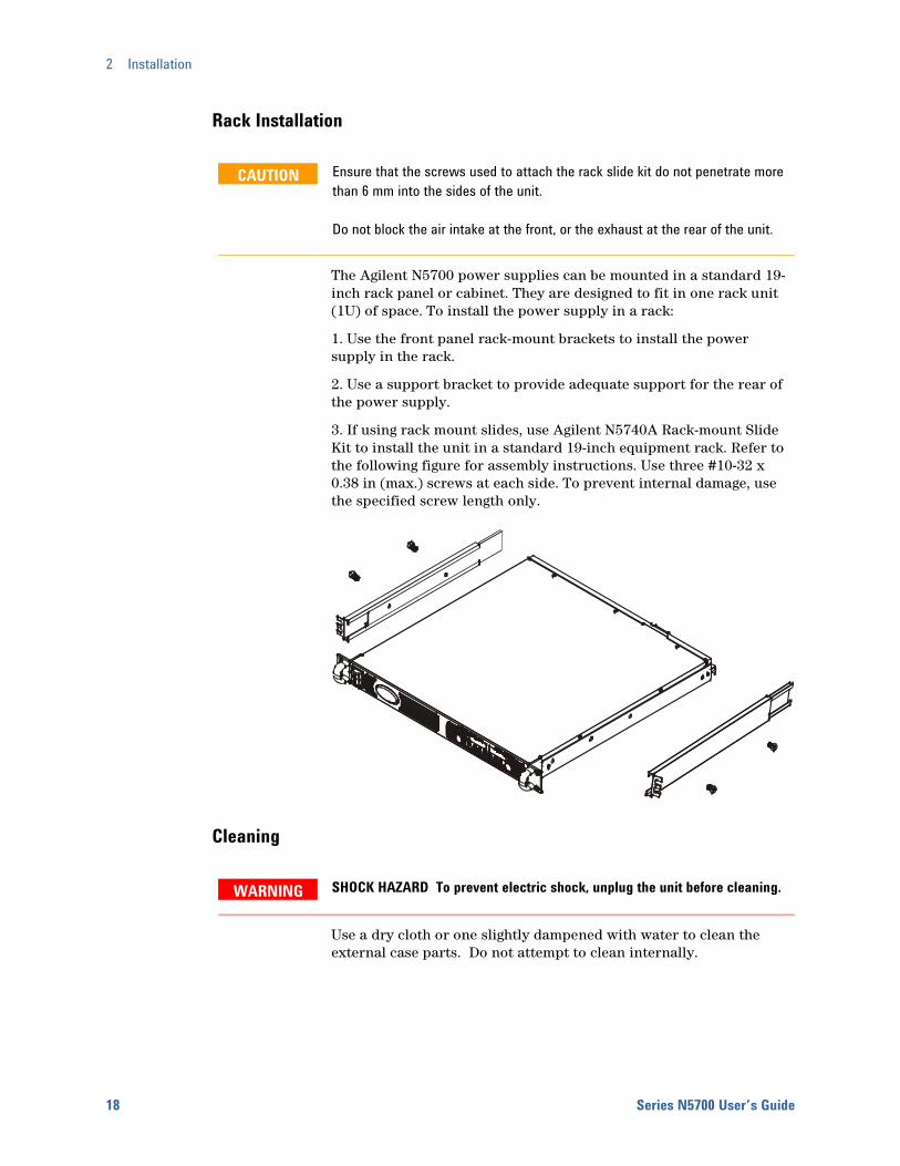
The Agilent N5700 power supplies can be mounted in a standard 19-inch rack panel or cabinet. They are designed to fit in one rack unit (1U) of space. To install the power supply in a rack:
1. Use the front panel rack-mount brackets to install the power supply in the rack.
2. Use a support bracket to provide adequate support for the rear of the power supply.
3. If using rack mount slides, use Agilent N5740A Rack-mount Slide Kit to install the unit in a standard 19-inch equipment rack. Refer to the following figure for assembly instructions. Use three #10-32 x 0.38 in (max.) screws at each side. To prevent internal damage, use the specified screw length only.
Cleaning
WARNING SHOCK HAZARD To prevent electric shock, unplug the unit before cleaning.
Use a dry cloth or one slightly dampened with water to clean the external case parts. Do not attempt to clean internally.

Installation 2
Series N5700 User’s Guide 19
Connecting the Line Cord
WARNING SHOCK HAZARD The power cord provides a chassis ground through a third conductor. Be certain that your power outlet is of the three-conductor type with the correct pin connected to earth ground.
FIRE HAZARD Use only the power cord that was supplied with your instrument. Using other types of power cords may cause overheating of the power cord, resulting in fire.
NOTE The detachable power cord may be used as an emergency disconnecting device. Removing the power cord will disconnect ac input power to the unit.
The AC input on the back of your unit is a universal AC input. It accepts line voltages in the range of 85 VAC to 265 VAC. The frequency range is 47 Hz to 63 Hz.
The input current requirement of 750W units is 10.5A @ 100 VAC nominal and 5A @ 200 VAC nominal. The current requirement of 1500W units is 21A @ 100 VAC nominal and 11A @ 200 VAC nominal.
Input Connections for 750W units Connect the power cord to the IEC 320 connector on the rear of the unit. The IEC connector provides the safety ground connection when the AC cord is plugged into a grounded AC receptacle.
If the wrong power cord was shipped with your unit, contact your nearest Agilent Sales and Service Office.
Input Connections for 1500W units
CAUTION Connection of this power supply to an AC power source should be made by a qualified electrician or other qualified personnel.
The AC input connector is a 3-terminal wire clamp located on the rear panel. Use suitable wires and tightening torque as follows:
• Wire diameter: 12 AWG or 10 AWG
• Tightening torque: 6.5 - 7.0 in-lb
Connect the cable to the AC input connector as follows:
• Strip the outside insulation of the AC cable approximately 10 cm (4 in). Trim the wires so that the ground wire is 10 mm (0.4 in) longer than the other wires. Strip 14 mm (0.55 in) at the end of each of the wires.
2 Installation
20 Series N5700 User’s Guide
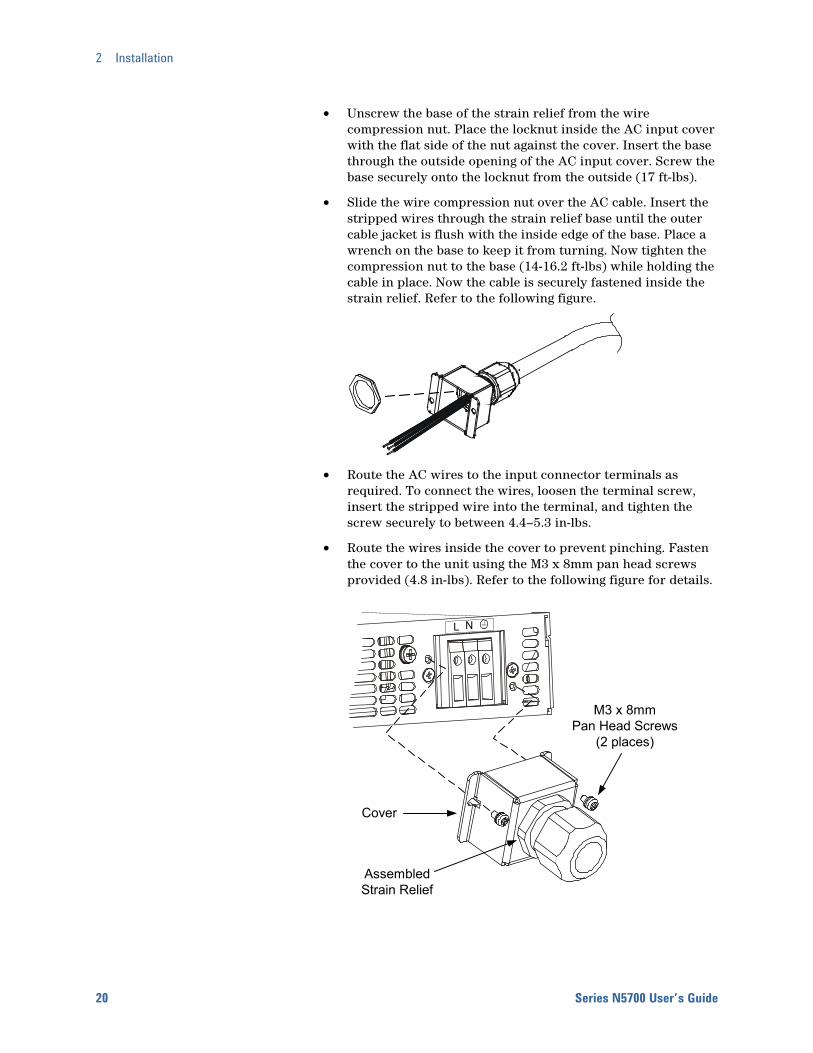
• Unscrew the base of the strain relief from the wire compression nut. Place the locknut inside the AC input cover with the flat side of the nut against the cover. Insert the base through the outside opening of the AC input cover. Screw the base securely onto the locknut from the outside (17 ft-lbs).
• Slide the wire compression nut over the AC cable. Insert the stripped wires through the strain relief base until the outer cable jacket is flush with the inside edge of the base. Place a wrench on the base to keep it from turning. Now tighten the compression nut to the base (14-16.2 ft-lbs) while holding the cable in place. Now the cable is securely fastened inside the strain relief. Refer to the following figure.
• Route the AC wires to the input connector terminals as required. To connect the wires, loosen the terminal screw, insert the stripped wire into the terminal, and tighten the screw securely to between 4.4–5.3 in-lbs.
• Route the wires inside the cover to prevent pinching. Fasten the cover to the unit using the M3 x 8mm pan head screws provided (4.8 in-lbs). Refer to the following figure for details.
L N
Cover
AssembledStrain Relief
M3 x 8mmPan Head Screws
(2 places)
Installation 2
Series N5700 User’s Guide 21
Connecting the Load
WARNING SHOCK HAZARD Turn off AC power before making rear panel connections. All wires and straps must be properly connected with screws securely tightened.
As further explained in this section, the following factors should be considered when selecting wiring to connect the load to the power supply:
• Current carrying capacity of the wire
• Insulation rating of the wire should be at least equivalent to the maximum output voltage of the power supply
• Maximum wire length and voltage drop
• Noise and impedance effects of the load wiring
Wire Size
WARNING FIRE HAZARD To satisfy safety requirements, select a wire size heavy enough not to overheat while carrying the power supply load current at the rated load, or the current that would flow in the event the load wires were shorted, whichever is greater.
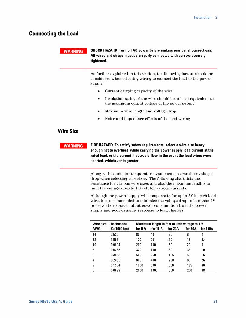
Along with conductor temperature, you must also consider voltage drop when selecting wire sizes. The following chart lists the resistance for various wire sizes and also the maximum lengths to limit the voltage drop to 1.0 volt for various currents.
Although the power supply will compensate for up to 5V in each load wire, it is recommended to minimize the voltage drop to less than 1V to prevent excessive output power consumption from the power supply and poor dynamic response to load changes.
Wire sizeAWG
Resistance ΩΩΩΩ/1000 foot
Maximum length in feet to limit voltage to 1 V for 5 A for 10 A for 20A for 50A for 150A
14 2.526 80 40 20 8 2 12 1.589 120 60 30 12 3.4 10 0.9994 200 100 50 20 6 8 0.6285 320 160 80 32 10 6 0.3953 500 250 125 50 16 4 0.2486 800 400 200 80 26 2 0.1564 1200 600 300 125 40 0 0.0983 2000 1000 500 200 68
2 Installation
22 Series N5700 User’s Guide
Cross section (mm2)
Resistance ΩΩΩΩ/kilometer
Maximum length in meters to limit voltage to 1 V for 5 A for 10 A for 20A for 50A for 150A
2.5 8.21 24.0 12.0 6.0 2.4 0.8 4 5.09 39.2 18.6 9.8 4.0 1.4 6 3.39 59.0 29.4 14.8 5.8 2.0 10 1.95 102 51.2 25.6 10.2 3.4 16 1.24 160 80.0 40.0 16.0 5.4 25 0.795 250 125 62.0 25.2 8.4 35 0.565 354 177 88.0 35.4 11.8
Load Connections for 6V to 60V Models
WARNING SHOCK HAZARD Hazardous voltages may exist at the outputs and the load connections when using a power supply with a rated output greater than 40V. To protect personnel against accidental contact with hazardous voltages, ensure that the load and its connections have no accessible live parts. Ensure that the load wiring insulation rating is greater than or equal to the maximum output voltage of the power supply.
CAUTION Ensure that the load wiring mounting hardware does not short the output terminals. Heavy connecting cables must have some form of strain relief to prevent loosening the connections or bending the bus-bars.
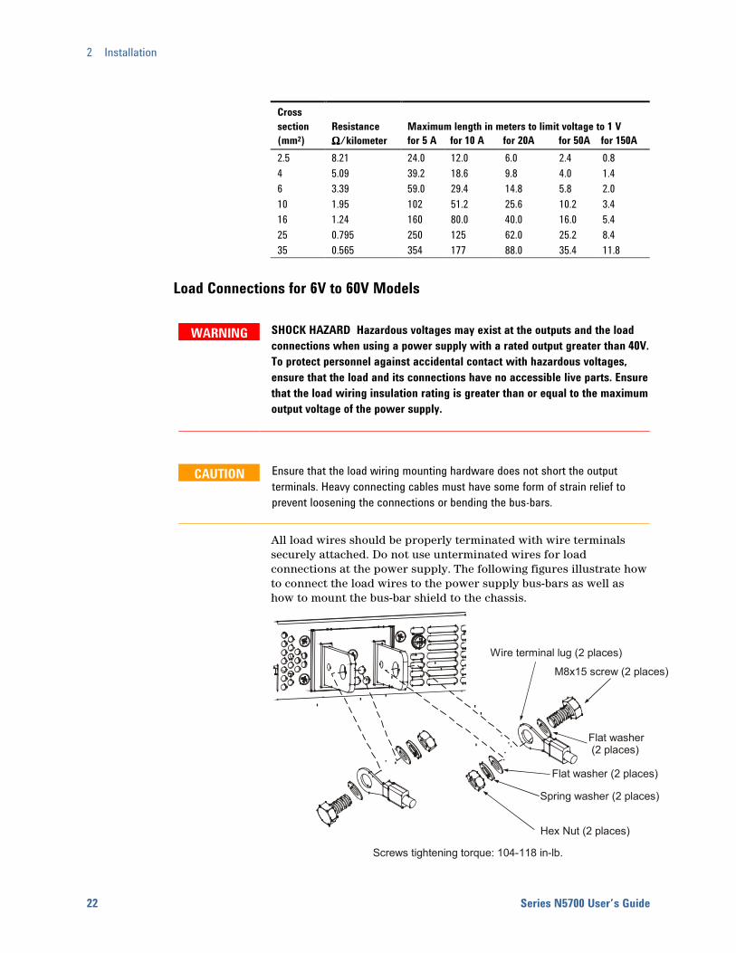
All load wires should be properly terminated with wire terminals securely attached. Do not use unterminated wires for load connections at the power supply. The following figures illustrate how to connect the load wires to the power supply bus-bars as well as how to mount the bus-bar shield to the chassis.
M8x15 screw (2 places)
Hex Nut (2 places)
Flat washer (2 places)
Spring washer (2 places)
Wire terminal lug (2 places)
Flat washer (2 places)
Screws tightening torque: 104-118 in-lb.
Installation 2
Series N5700 User’s Guide 23
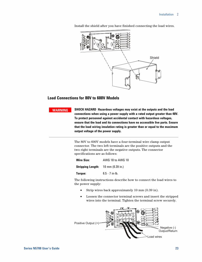
Install the shield after you have finished connecting the load wires.
Load Connections for 80V to 600V Models
WARNING SHOCK HAZARD Hazardous voltages may exist at the outputs and the load connections when using a power supply with a rated output greater than 40V. To protect personnel against accidental contact with hazardous voltages, ensure that the load and its connections have no accessible live parts. Ensure that the load wiring insulation rating is greater than or equal to the maximum output voltage of the power supply.
The 80V to 600V models have a four-terminal wire clamp output connector. The two left terminals are the positive outputs and the two right terminals are the negative outputs. The connector specifications are as follows:
Wire Size: AWG 18 to AWG 10
Stripping Length: 10 mm (0.39 in.)
Torque: 6.5 - 7 in-lb.
The following instructions describe how to connect the load wires to the power supply:
• Strip wires back approximately 10 mm (0.39 in).
• Loosen the connector terminal screws and insert the stripped wires into the terminal. Tighten the terminal screw securely.
Shield
Load wires
Negative (-) Output/Return
Positive Output (+)
+V -V
2 Installation
24 Series N5700 User’s Guide
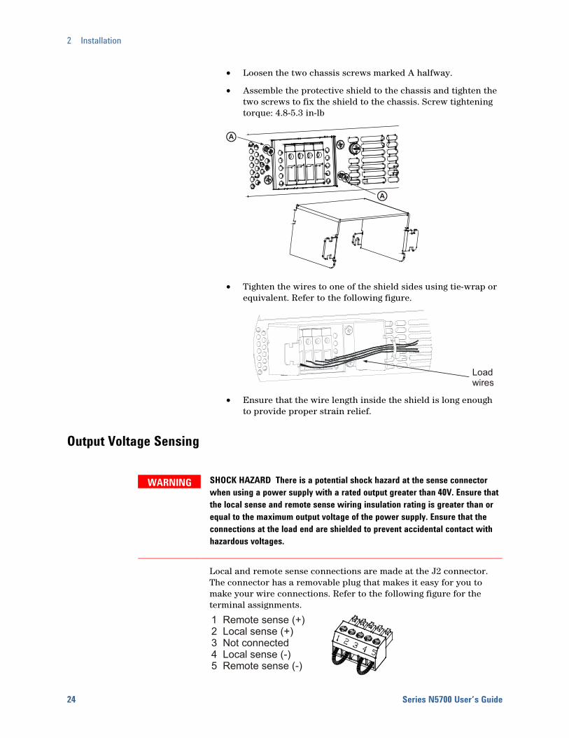
• Loosen the two chassis screws marked A halfway.
• Assemble the protective shield to the chassis and tighten the two screws to fix the shield to the chassis. Screw tightening torque: 4.8-5.3 in-lb
• Tighten the wires to one of the shield sides using tie-wrap or equivalent. Refer to the following figure.
• Ensure that the wire length inside the shield is long enough to provide proper strain relief.
Output Voltage Sensing
WARNING SHOCK HAZARD There is a potential shock hazard at the sense connector when using a power supply with a rated output greater than 40V. Ensure that the local sense and remote sense wiring insulation rating is greater than or equal to the maximum output voltage of the power supply. Ensure that the connections at the load end are shielded to prevent accidental contact with hazardous voltages.
Local and remote sense connections are made at the J2 connector. The connector has a removable plug that makes it easy for you to make your wire connections. Refer to the following figure for the terminal assignments.
A
A
Loadwires
1 Remote sense (+)2 Local sense (+)3 Not connected4 Local sense (-)5 Remote sense (-)
Installation 2
Series N5700 User’s Guide 25
The J2 connector plug specifications are as follows:
Plug Type: MC 1.5/5-ST-3.81, Phoenix
Wire Size: AWG 28 to AWG 16
Stripping Length: 7 mm (0.28 in.)
Torque: 0.22 – 0.25 Nm (1.95 – 2.21 in-lb.)
NOTE If the power supply is operated without the remote sense lines connected or without local sense jumpers, it will continue to work, but the output voltage regulation will be degraded. Also, the OVP circuit may activate and shut down the power supply.
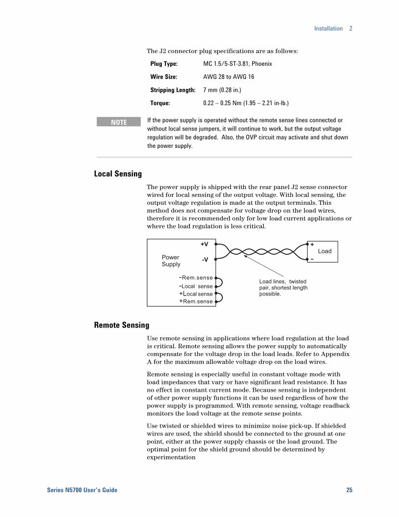
Local Sensing The power supply is shipped with the rear panel J2 sense connector wired for local sensing of the output voltage. With local sensing, the output voltage regulation is made at the output terminals. This method does not compensate for voltage drop on the load wires, therefore it is recommended only for low load current applications or where the load regulation is less critical.
Remote Sensing Use remote sensing in applications where load regulation at the load is critical. Remote sensing allows the power supply to automatically compensate for the voltage drop in the load leads. Refer to Appendix A for the maximum allowable voltage drop on the load wires.
Remote sensing is especially useful in constant voltage mode with load impedances that vary or have significant lead resistance. It has no effect in constant current mode. Because sensing is independent of other power supply functions it can be used regardless of how the power supply is programmed. With remote sensing, voltage readback monitors the load voltage at the remote sense points.
Use twisted or shielded wires to minimize noise pick-up. If shielded wires are used, the shield should be connected to the ground at one point, either at the power supply chassis or the load ground. The optimal point for the shield ground should be determined by experimentation
--Rem.senseLocal sense
ocal senseRem.sense
+L+
Load lines, twisted pair, shortest length possible.
+V
-VLoad
+
Power Supply
2 Installation
26 Series N5700 User’s Guide
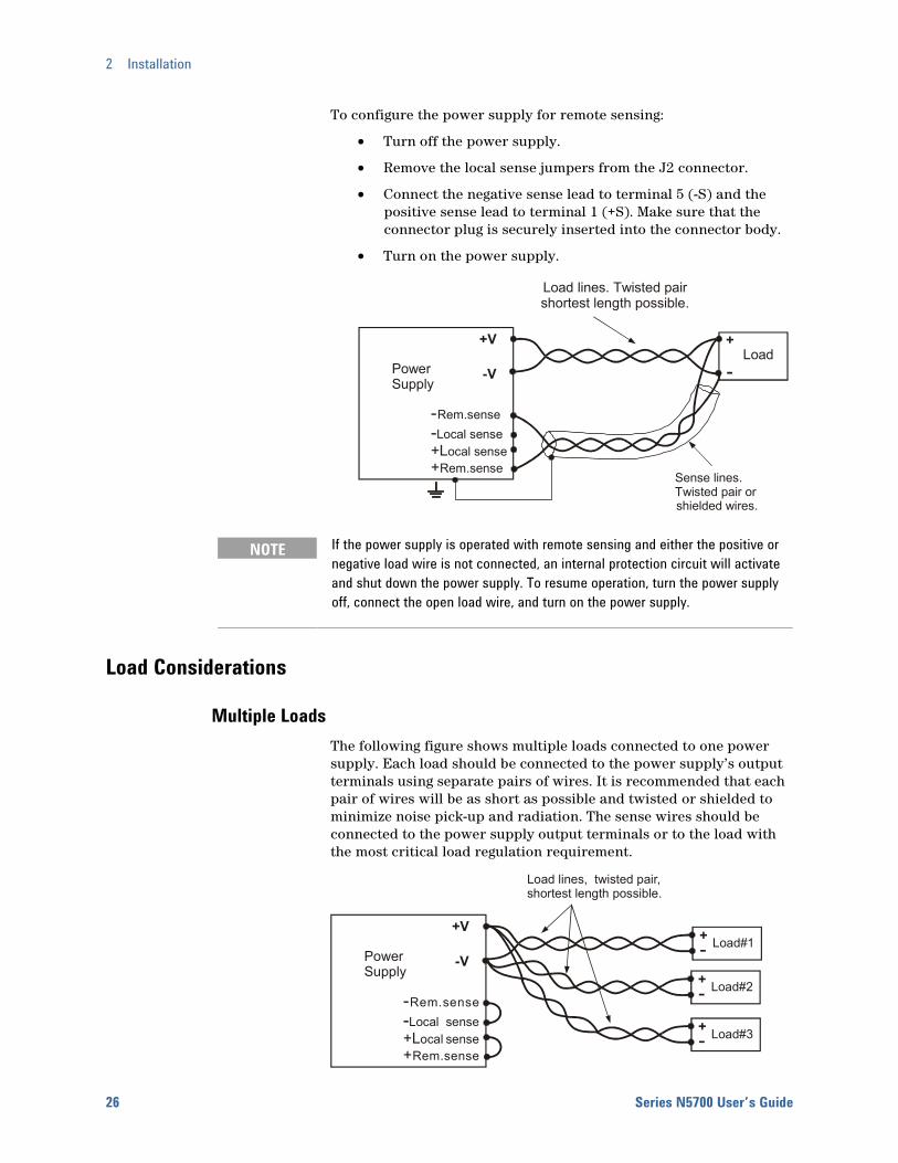
To configure the power supply for remote sensing:
• Turn off the power supply.
• Remove the local sense jumpers from the J2 connector.
• Connect the negative sense lead to terminal 5 (-S) and the positive sense lead to terminal 1 (+S). Make sure that the connector plug is securely inserted into the connector body.
• Turn on the power supply.
NOTE If the power supply is operated with remote sensing and either the positive or negative load wire is not connected, an internal protection circuit will activate and shut down the power supply. To resume operation, turn the power supply off, connect the open load wire, and turn on the power supply.
Load Considerations
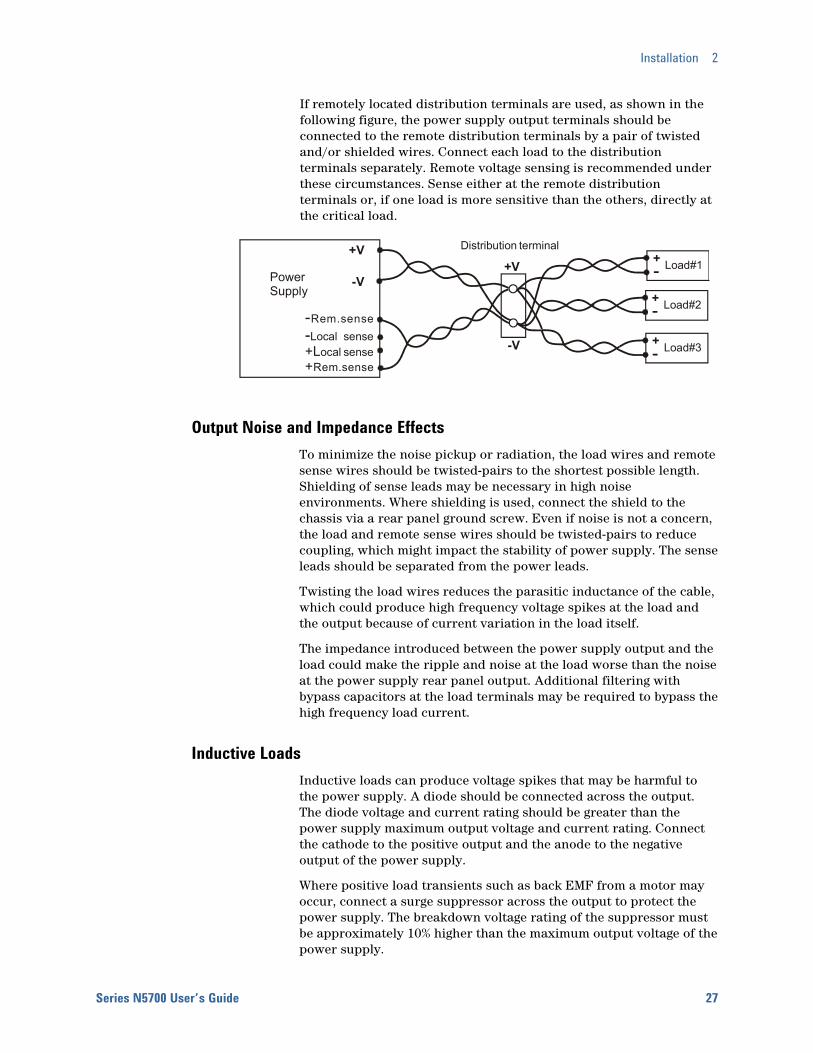
Multiple Loads The following figure shows multiple loads connected to one power supply. Each load should be connected to the power supply’s output terminals using separate pairs of wires. It is recommended that each pair of wires will be as short as possible and twisted or shielded to minimize noise pick-up and radiation. The sense wires should be connected to the power supply output terminals or to the load with the most critical load regulation requirement.
--Rem.senseLocal sense
ocal senseRem.sense
+L+
Load lines, twisted pair, shortest length possible.
+V
-VLoad#1+
Load#3+
Load#2+Power Supply
--Rem.senseLocal sense
ocal senseRem.sense
+L+
Sense lines.Twisted pair or
+V
-VLoad
+
PowerSupply
Load lines. Twisted pairshortest length possible.
shielded wires.
Installation 2
Series N5700 User’s Guide 27
If remotely located distribution terminals are used, as shown in the following figure, the power supply output terminals should be connected to the remote distribution terminals by a pair of twisted and/or shielded wires. Connect each load to the distribution terminals separately. Remote voltage sensing is recommended under these circumstances. Sense either at the remote distribution terminals or, if one load is more sensitive than the others, directly at the critical load.
Output Noise and Impedance Effects To minimize the noise pickup or radiation, the load wires and remote sense wires should be twisted-pairs to the shortest possible length. Shielding of sense leads may be necessary in high noise environments. Where shielding is used, connect the shield to the chassis via a rear panel ground screw. Even if noise is not a concern, the load and remote sense wires should be twisted-pairs to reduce coupling, which might impact the stability of power supply. The sense leads should be separated from the power leads.
Twisting the load wires reduces the parasitic inductance of the cable, which could produce high frequency voltage spikes at the load and the output because of current variation in the load itself.
The impedance introduced between the power supply output and the load could make the ripple and noise at the load worse than the noise at the power supply rear panel output. Additional filtering with bypass capacitors at the load terminals may be required to bypass the high frequency load current.
Inductive Loads Inductive loads can produce voltage spikes that may be harmful to the power supply. A diode should be connected across the output. The diode voltage and current rating should be greater than the power supply maximum output voltage and current rating. Connect the cathode to the positive output and the anode to the negative output of the power supply.
Where positive load transients such as back EMF from a motor may occur, connect a surge suppressor across the output to protect the power supply. The breakdown voltage rating of the suppressor must be approximately 10% higher than the maximum output voltage of the power supply.
--Rem.senseLocal sense
ocal senseRem.sense
+L+
Distribution terminal+V+V
-V
-V
Load#1+
Load#3+
Load#2+Power Supply

2 Installation
28 Series N5700 User’s Guide
Grounding the Output The output of the power supply is isolated from earth ground. Either positive or negative voltages can be obtained from the output by grounding (or "commoning") one of the output terminals. Always use two wires to connect the load to the output regardless of where or how the system is grounded.
To avoid noise problems caused by common-mode current flowing from the load to ground, it is recommended to ground the output terminal as close as possible to the power supply chassis ground.
WARNING SHOCK HAZARD For models up to 60VDC rated output, no point shall be more than +/-60VDC above/below chassis ground. For models > 60VDC rated output, no point shall be more than +/-600VDC above/below chassis ground.
There is also a potential shock hazard at the IEEE/LAN/USB ports when using power supplies with rated or combined voltages > 400VDC with the positive output of the power supplies grounded. Do not connect the positive output to ground when using the IEEE/LAN/USB under the above conditions.
Parallel Connections
CAUTION Only power supplies that have identical voltage and current ratings can be connected in parallel.
Up to four units of the same voltage and current rating can be connected in parallel to provide up to four times the output current capability. Refer to the following figures for typical connections of parallel power supplies using either local or remote sensing. The figures show two units, however, the same connection method applies for up to four units.
Local Sensing
+V
-V
+V
-V
+S+LS-S -LS
+S+LS-S -LS
MASTERPOWER SUPPLY
SLAVEPOWER SUPPLY
LOADJ1-25
J1-10
ParallelCurrent Program
As short as possible
Twisted pair
J1-8 J1-12
Installation 2
Series N5700 User’s Guide 29
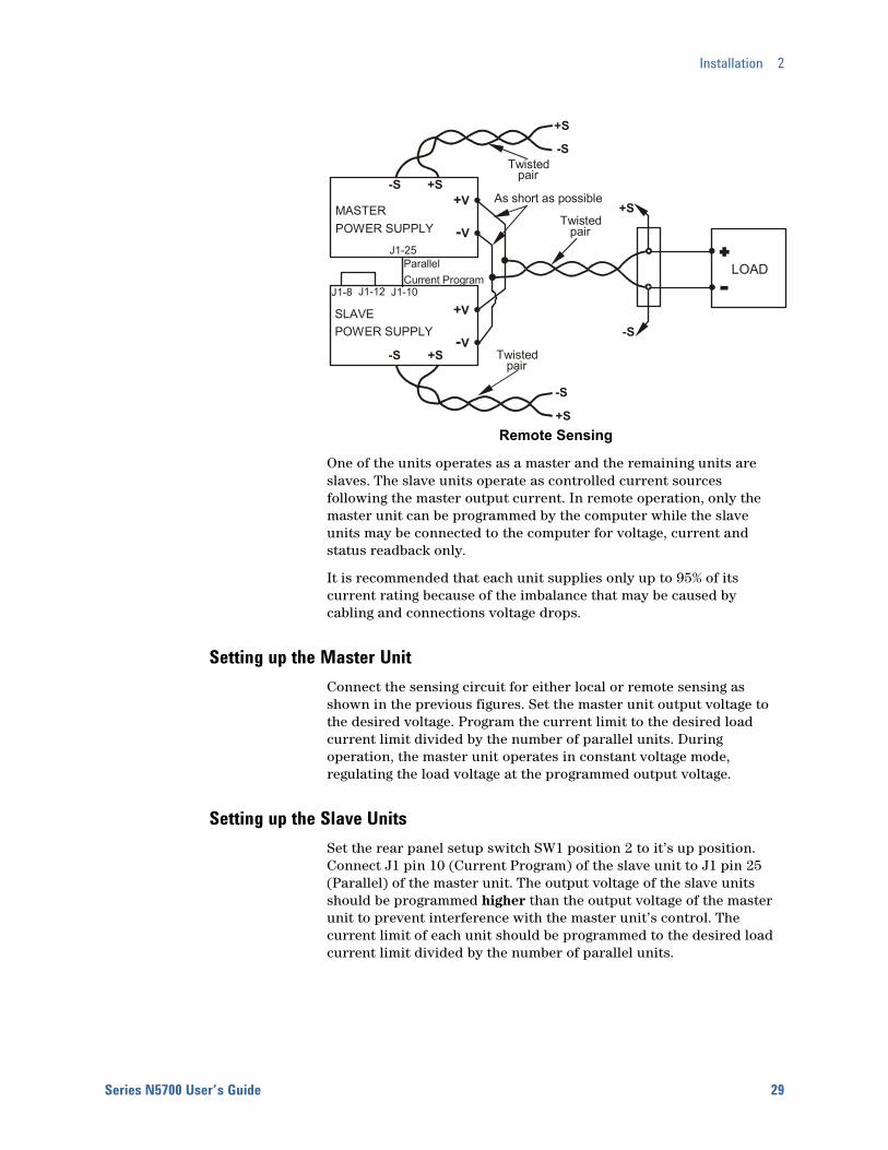
Remote Sensing
One of the units operates as a master and the remaining units are slaves. The slave units operate as controlled current sources following the master output current. In remote operation, only the master unit can be programmed by the computer while the slave units may be connected to the computer for voltage, current and status readback only.
It is recommended that each unit supplies only up to 95% of its current rating because of the imbalance that may be caused by cabling and connections voltage drops.
Setting up the Master Unit Connect the sensing circuit for either local or remote sensing as shown in the previous figures. Set the master unit output voltage to the desired voltage. Program the current limit to the desired load current limit divided by the number of parallel units. During operation, the master unit operates in constant voltage mode, regulating the load voltage at the programmed output voltage.
Setting up the Slave Units Set the rear panel setup switch SW1 position 2 to it’s up position. Connect J1 pin 10 (Current Program) of the slave unit to J1 pin 25 (Parallel) of the master unit. The output voltage of the slave units should be programmed higher than the output voltage of the master unit to prevent interference with the master unit’s control. The current limit of each unit should be programmed to the desired load current limit divided by the number of parallel units.
+V
-V
+V
-V
+S-S
+S-S
MASTERPOWER SUPPLY
SLAVEPOWER SUPPLY
+S
-S
+S
+S
-S
-S
LOADJ1-25
J1-10
ParallelCurrent Program
As short as possible
Twisted pair
Twisted pair
Twisted pair
J1-8 J1-12
2 Installation
30 Series N5700 User’s Guide
Setting the Over-Voltage Protection The master unit OVP should be programmed to the desired OVP level. The OVP of the slave units should be programmed to a higher value than the master. When the master unit shuts down, it programs the slave unit to zero output voltage. If a slave unit shuts down when its OVP is set lower than the master output voltage, only that unit shuts down and the remaining slave units will supply all the load current.
Setting the Over-Current Protection Over-current protection, if desired, may only be used with the master unit. When the master unit shuts down, it programs the slave units to zero output voltage.
Series Connections
WARNING SHOCK HAZARD For models up to 60VDC rated output, no point shall be more than +/-60VDC above/below chassis ground. For models > 60VDC rated output, no point shall be more than +/-600VDC above/below chassis ground.
There is also a potential shock hazard at the IEEE/LAN/USB ports when using power supplies with rated or combined voltages > 400VDC with the positive output of the power supplies grounded. Do not connect the positive output to ground when using the IEEE/LAN/USB under the above conditions.
CAUTION Only power supplies that have identical voltage and current ratings can be connected in series.
Two units of the same voltage and current rating can be connected in series to provide up to two times the output voltage capability. Because the current is the same through each element in a series circuit, outputs connected in series must have equivalent current ratings. Otherwise, the higher rated output could potentially damage the lower rated output by forcing excessive current through it under certain load conditions. Refer to the following figures for typical series connections using either local or remote sensing.
It is recommended that diodes be connected in parallel with each output to prevent reverse voltage during start up sequence or in case one unit shuts down. Each diode should be rated to at least the rated output voltage and output current of the power supply.
Installation 2
Series N5700 User’s Guide 31
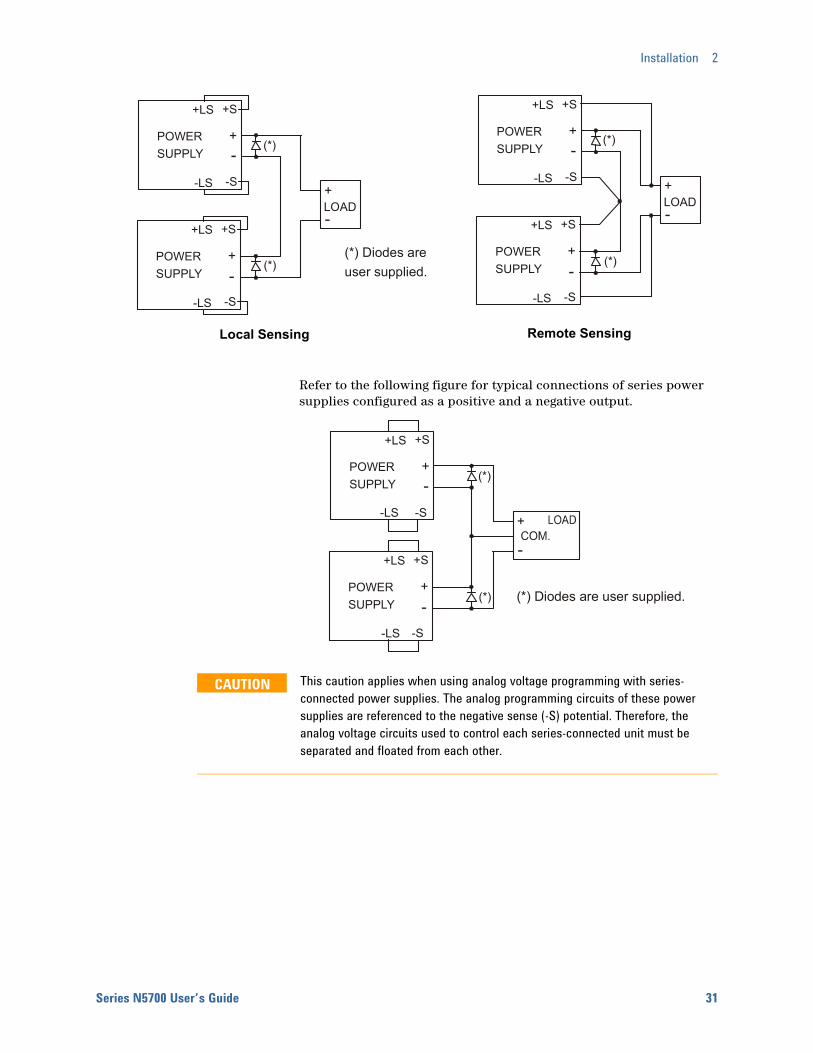
Local Sensing Remote Sensing
Refer to the following figure for typical connections of series power supplies configured as a positive and a negative output.
CAUTION This caution applies when using analog voltage programming with series-connected power supplies. The analog programming circuits of these power supplies are referenced to the negative sense (-S) potential. Therefore, the analog voltage circuits used to control each series-connected unit must be separated and floated from each other.
+S
+-
-S-LS
+LS
POWERSUPPLY
+S
+
+
-
-
-S-LS
+LS
POWERSUPPLY
LOAD
(*)
(*)
+S
+-
-S-LS
+LS
POWERSUPPLY
+S
+
+
-
-
-S-LS
+LS
POWERSUPPLY
LOAD
(*)
(*)
(*) Diodes areuser supplied.
+S
+-
-S-LS
+LS
POWERSUPPLY
+S
+
+
-
-
-S-LS
+LS
POWERSUPPLY (*)
(*)
(*) Diodes are user supplied.

2 Installation
32 Series N5700 User’s Guide
J1 Connector Connections
WARNING SHOCK HAZARD There is a potential shock hazard at the J1 connector when using a power supply with a rated output greater than 40V. Ensure that the load wiring insulation rating is greater than or equal to the maximum output voltage of the power supply.
External programming and monitoring signal are located on the J1 connector. The power supply is shipped with a mating plug that makes it easy for you to make your wire connections. It is essential to use this plastic-body plug to conform to safety agency requirements. If a shield is required for the J1 wires, connect the shield to the ground screw located on the power supply chassis.
Refer to the following figure for the pin assignments. A description of the pins is given in chapter 1.
The mating plug specifications for the J1 connector are as follows:
Mating Plug: AMP part number 745211-2
Wire Size: AWG 26 to AWG 22
Extraction tool: AMP part number 91232-1 or equivalent
Manual pistol grip tool: Handle: AMP p/n 58074-1 Head: AMP p/n 58063-1
CAUTION Pins 12, 22 and 23 of J1 are connected internally to the negative sense (-S) potential of the power supply. Do not attempt to bias any of these pins relative to the negative output terminal. Use an isolated, ungrounded, programming source to prevent ground loops and to maintain the isolation of the power supply when programming from J1.
Chapter 3 describes how to configure the J1 connector when using it to program the output voltage and current.
141516171819202122232425
1234567810111213 9
Current MonitorCurrent Prog. ReturnVoltage Prog. ReturnLocal / Analog State
Chassis Common
Enable +
Voltage MonitorCommon (-S)
CV / CC
Current ProgramVoltage ProgramLocal / Analog
Parallel Enable --Shut OffPower Supply OK
Chassis Common
Pins on this side are isolatedfrom output terminals and arereferenced to chassis ground.
Pins on this side arereferenced to the negativesense (-S) terminal.
Series N5700 User’s Guide 33
3 Operating the Power Supply Locally Turn-On Check-Out ........................................................................................... 34 Normal Operation.............................................................................................. 36 Protection Functions ........................................................................................ 37 Output On/Off Controls.................................................................................... 40 Analog Programming of Output Voltage and Current................................. 42
This chapter contains examples on how to operate your power supply from the front panel. A check-out procedure is included to let you verify that the power supply is operating properly. Additionally, information about programming the power supply using the J1 analog programming connector is also provided.
The simple examples discussed in this chapter show you how to program:
output voltage and current functions
protection functions
output on/off functions
safe-start and auto-restart
analog programming of voltage and current
front panel locking
Refer to chapters 4 and 5 for information on programming your power supply using SCPI commands.
3 Operating the Power Supply Locally
34 Series N5700 User’s Guide
Turn-On Check-Out
Before Check-Out Ensure that the power supply is configured as follows:
• The unit is connected to an appropriate AC source as described in chapter 2.
• The POWER switch is in the off position.
• Sense connector pins 1 and 2 are jumpered; sense connector pins 4 and 5 are jumpered.
• All switches on Connector J2 are in the down position.
WARNING SHOCK HAZARD Be aware that hazardous voltages can be present on the output terminals. Do not set the output voltage above 40 VDC during the turn-on check-out procedure.
Constant Voltage Check • Turn the POWER switch on.
• Turn the output on by pressing the OUT ON button. The green OUT ON indicator should be illuminated.
• The green CV indicator should also be illuminated. If the CC indicator is illuminated, rotate the current knob until the CV indicator becomes illuminated.
• Rotate the voltage knob while observing the DC VOLTS display. The output voltage should vary while the knob is turned. The voltage range is from zero to the maximum rated output for the power supply model.
OVP Check • Rotate the voltage knob and set the output voltage of the unit
to 50% of its full-scale rating or 30 volts, whichever is lower.
• Press the OVP/UVL button once so that the DC AMPS display indicates OUP. The DC VOLTS display shows the OVP level.
• Use the voltage knob and set the OVP level of the unit to 75% of its full-scale voltage rating or 40 volts, whichever is lower.
• Wait a few seconds until the DC VOLTS display returns to show the output voltage.
• Use the voltage knob and raise the output voltage of the unit until it approaches the OVP setting. Check to make sure that the output voltage cannot be set higher than the OVP setting.
• Press the OVP/UVL button again. Rotate the voltage knob and reset the OVP level of the unit to its maximum setting.
Operating the Power Supply Locally 3
Series N5700 User’s Guide 35
UVL Check • Press the OVP/UVL button twice so that the DC AMPS display
indicates UUL. The DC VOLTS display shows the UVL level.
• Use the voltage knob and set the UVL level of the unit to 50% of its full-scale voltage rating or 30 volts, whichever is lower.
• Wait a few seconds until the DC VOLTS display returns to show the output voltage.
• Use the voltage knob and lower the output voltage of the unit until it approaches the UVL setting. Check to make sure that the output voltage cannot be set lower than the UVL setting.
• Press the OVP/UVL button twice. Rotate the voltage knob and reset the UVL level of the unit to its minimum setting.
Constant Current Check • Turn the POWER switch off. Wait a few seconds until the AC
indicator on the front panel goes out.
• Use a heavy wire and short the +V and –V output terminals together.
• Turn the POWER switch on.
• Turn the output on by pressing the OUT ON button. The green OUT ON indicator should be illuminated. The green CC indicator should be also illuminated.
• Rotate the current knob while observing the DC AMPS display. The output current should vary while the knob is turned. The current range is from zero to the maximum rated output for the power supply model.
OCP Check • Rotate the current knob and set the current limit of the unit
to about 10% of its full-scale current rating.
• Press the OCP button. This should trip the OCP protection. The OCP indicator should be illuminated, the DC VOLTS display should indicate OCP, and the Alarm indicator should be blinking.
• Press the OCP button again to cancel OCP protection. The DC VOLTS display should indicate OFF because the OCP protection is latched.
• Press the OUT ON button to reset the OCP protection. The output should return to its previous setting.
• Turn the POWER switch off.
• Remove the short from the +V and –V output terminals.
3 Operating the Power Supply Locally
36 Series N5700 User’s Guide
Normal Operation The power supply has two basic operating modes: constant voltage and constant current mode. In constant voltage mode, the power supply regulates the output voltage at the selected value, while the load current varies as required by the load. In constant current mode, the power supply regulates the output current at the selected value, while the voltage varies as required by the load. The mode in which the power supply operates at any given time depends on the voltage setting, current limit setting, and the load resistance.
Constant Voltage Mode When the power supply is operating in constant voltage mode, the CV indicator on the front panel illuminates.
Adjustment of the output voltage can be made when the output is enabled (On) or disabled (Off). When the output is enabled, simply rotate the voltage knob to program the output voltage.
When the output is disabled, press the LIMIT button and then rotate the voltage knob. The DC VOLTS display will show the programmed voltage for 5 seconds after the adjustment has been completed and then indicate OFF.
The voltage knob can be set to coarse or fine resolution. Press the FINE button to select finer resolution. The FINE indicator turns on.
NOTE If you cannot adjust the voltage to the value that you desire, the power supply may be operating at its current limit. Check the load condition and the current limit setting. Also, the voltage cannot be programmed lower than about 5% above the UVL setting, or higher than about 5% below the OVP setting.
Constant Current Mode When the power supply is operating in constant current mode, the CC indicator on the front panel illuminates.
Adjustment of the output current limit can be made when the output is enabled (On) or disabled (Off). When the output is enabled and in constant current mode, simply rotate the current knob to program the current limit. If the output is in constant voltage mode, press the LIMIT button and then rotate the current knob. The DC AMPS display will show the programmed current for 5 seconds after the adjustment has been completed and then indicate the actual output current.
When the output is disabled, press the LIMIT button and then rotate the current knob. The DC AMPS display will show the programmed current for 5 seconds after the adjustment has been completed and then go blank because the output is off.
The current knob can be set to coarse or fine resolution. Press the FINE button to select finer resolution. The FINE indicator turns on.
Operating the Power Supply Locally 3
Series N5700 User’s Guide 37
CV/CC Mode Crossover If the power supply is in constant voltage mode and the load current increases above the current limit setting, the power supply switches to constant current mode. If the load decreases below the current limit setting, the power supply switches to constant voltage mode.
CV/CC Signal
CAUTION Do not connect the CV/CC signal to a voltage source higher than 30VDC. Always connect the CV/CC signal to the voltage source with a series resistor to limit the sink current to less than 10mA.
The CV/CC signal available on the J1 connector indicates the operating mode of the power supply. The CV/CC signal is an open collector output with a 30V parallel zener at J1 pin 13, referenced to common at J1 pin 12. J1 pin 12 is connected internally to the –S terminal. When the power supply operates in constant voltage mode, CV/CC output is open. When the power supply operates in constant current mode, CV/CC signal output is low (0 - 0.6V), with maximum 10mA sink current.
Protection Functions
Over-Voltage Protection The over-voltage protection protects against over-voltage conditions on the output. If the output voltage attempts to exceed the programmed limit in response to an analog programming signal or in the event of a power supply failure, the over-voltage protection circuit will protect the load by disabling the output. The voltage is monitored at the sense terminals, thus providing the protection level directly at the load. Upon detection of an over-voltage condition, the output is disabled, the display shows OVP, the PROT indicator blinks, and OV is set in the Questionable Condition status register.
Adjustment of the over-voltage setting can be made when the output is enabled (On) or disabled (Off). To set the OVP level, press the OVP/UVL button so that the display indicates OUP. The display will show the OVP setting. Rotate the voltage knob to adjust the OVP level. The display will show OVP and the setting value for another five seconds and then return to its previous state.
The OVP settings are limited at the minimum level to approximately 5% above the output voltage setting. Attempting to adjust the OVP below this limit will result in no response to the adjustment attempt. Refer to Appendix A for the maximum OVP settings.
Use one of the following methods to reset the OVP circuit after it activates. If the condition that caused the over-voltage shutdown is still present, the OVP circuit will turn the output off again.
3 Operating the Power Supply Locally
38 Series N5700 User’s Guide
• Press the OUT ON button to turn the output on.
• Turn the AC power off, wait a few seconds, and turn it on.
• Turn the output off, then on again using the Shut Off pin on the J1 connector. This only applies in Auto-Restart mode.
• If the OVP continues to trip, try lowering the output voltage below the OVP setting, or raising the OVP setting.
Under-Voltage Limit The under-voltage limit prevents adjustment of the output voltage below a certain limit. The combination of UVL and OVP functions let you create a protection window for sensitive load circuitry.
Setting the UVL can be made when the output is enabled (On) or disabled (Off). To set the UVL level, press the OVP/UVL button twice, so that the display shows UUL. The display will show the UVL setting. Rotate the voltage knob to adjust the UVL level. The display will show UUL and the setting value for another five seconds and then return to its previous state.
The UVL settings are limited at the maximum level to approximately 5% below the output voltage setting. Attempting to adjust the UVL above this limit will result in no response to the adjustment attempt. The minimum UVL setting is zero.
Over-Current Protection Over-current protection will shut down the power supply output if the load current exceeds the current limit setting. This protection is useful when the load is sensitive to an over-current condition.
To arm the over-current protection, press the OCP button so that the OCP indicator illuminates. When armed, a transition from constant voltage to constant current mode will activate the over-current protection. When an over-current protection event occurs, the output is disabled, the display shows OCP, the PROT indicator blinks, and OC is set in the Questionable Condition status register.
Use one of the following methods to reset over-current protection after it activates. If the load current is still higher than the current limit setting, the over-current protection will be activated again.
• Press the OUT ON button to turn the output on.
• Turn the AC power off, wait a few seconds, and turn it on.
• Turn the output off, then on again using the Shut Off pin on the J1 connector. This only applies in Auto-Restart mode.
• Press the OCP button to cancel the over-current protection. The display will show OFF because OCP protection is latched. Press the OUT ON button to reset OCP. With this method, the over-current protection is disabled. If the load current is still higher than the current limit setting, the power supply will only attempt to limit the current at the current limit setting.

Operating the Power Supply Locally 3
Series N5700 User’s Guide 39
Over-Temperature Protection The over-temperature protection circuit shuts down the power supply before the internal components can exceed their safe internal operating temperature. This can occur if there is a cooling fan failure. When an OTP condition occurs, the output is disabled, the display shows O7P, the PROT indicator blinks, and the OT status bit is set in the Questionable Condition status register. Resetting the OTP circuit can be automatic (non-latched) or manual (latched) depending on the Safe-Start or Auto-Restart mode.
In Safe-Start mode, the OTP circuit is latched. The display continues to show O7P and the PROT indicator continues to blink. To reset the OTP circuit, press the OUT ON button.
In Auto-Restart mode, the OTP circuit is non-latched. The power supply returns to its last setting automatically when the over-temperature condition is removed.
Power-Fail Protection If the AC power stops briefly, but returns before the power supply has reset, the power-fail protection circuit trips and the PF status bit is set in the Questionable Condition status register. Resetting the power-fail protection can be automatic (non-latched) or manual (latched), depending on the Safe-Start or Auto-Restart mode.
In Safe-Start mode, the output of the power supply is Off, as specified by the reset state when AC power returns. In Auto-Restart mode, the power supply recovers its last settings when AC power returns.
Front Panel Lock-Out The front panel controls can be locked to protect from accidental power supply parameter change. Press and hold the LIMIT button to toggle between Locked front panel and Unlocked front panel. The display will cycle between LFP and UFP. Releasing the LIMIT button while one of the modes is displayed, selects that mode.
In Unlocked front panel mode, the front panel controls are enabled to program and monitor the power supply parameters.
In Locked front panel mode, the VOLTAGE and CURRENT knobs, the OCP button, and the OUT ON button are disabled
The power supply will not respond to attempts to use these controls. The display will show LFP to indicate that the front panel is locked. The OVP/UVL button remains active to preview the OVP and UVL setting. The LIMIT button also remains active to preview the output voltage and current setting or to unlock the front panel.
NOTE This function operates independently of the SCPI SYST:COMM:RLST command. If the front panel has been locked from the front panel, it cannot be unlocked by SYST:COMM:RLST. Conversely, if the front panel has been locked by SYST:COMM:RLST, it cannot be unlocked from the front panel.
3 Operating the Power Supply Locally
40 Series N5700 User’s Guide
Output On/Off Controls The Output On/Off controls turn the power supply output on or off. This can be done with the front panel OUT ON button or from the rear panel J1 connector. With the output off, adjustments can be made to the power supply or the load without shutting off AC power.
OUT ON button The OUT ON button can be pressed at any time to enable or disable the power supply output. When the output is disabled, the output voltage and current go to zero and the display shows OFF.
Safe-Start and Auto-Restart The power supply can be programmed to have either the last operating settings (Auto-Restart) or the reset settings (Safe-Start) apply at turn-on. Press and hold the OUT ON button to select between Safe-Start and Auto-Restart modes. The display continuously cycles between SAF and AUT every three seconds. Releasing the OUT ON button while one of the modes is displayed, selects that mode.
In Safe-Start mode, the power supply turns on with the reset settings (see chapter 5 under “*RST”). The output is disabled and the output voltage and current are zero. This is the factory default.
In Auto-Restart mode, the power supply restores the operating settings that were saved when it was last turned off (see below). The output is either enabled or disabled according to its last setting.
Output On/Off state UVL level
Output voltage setting OCP setting
Output current setting Locked/Unlocked front panel
OVP level Start-up mode
Output Shut-Off Terminals Output Shut-Off (SO) terminals are available on the J1 connector to enable or disable the power supply output. This function is edge-triggered. J1 pin 15 is the Shut-Off input, and pins 2 and 3, which are connected internally, are the signal common. All pins are optically isolated from the power supply output. The Shut-Off input accepts a 2.5V-to-15V signal or an open/short contact to enable or disable the output. The Shut-Off control logic is selected by SW1 setup switch 5.
When an on-to-off transition is detected at the Shut-Off input, the Shut-Off function enables or disables the output according to the signal level or the open/short applied to J1 pin 15. When the output has been disabled by the Shut-Off function, the display shows SO to indicate the output is disabled.
Operating the Power Supply Locally 3
Series N5700 User’s Guide 41
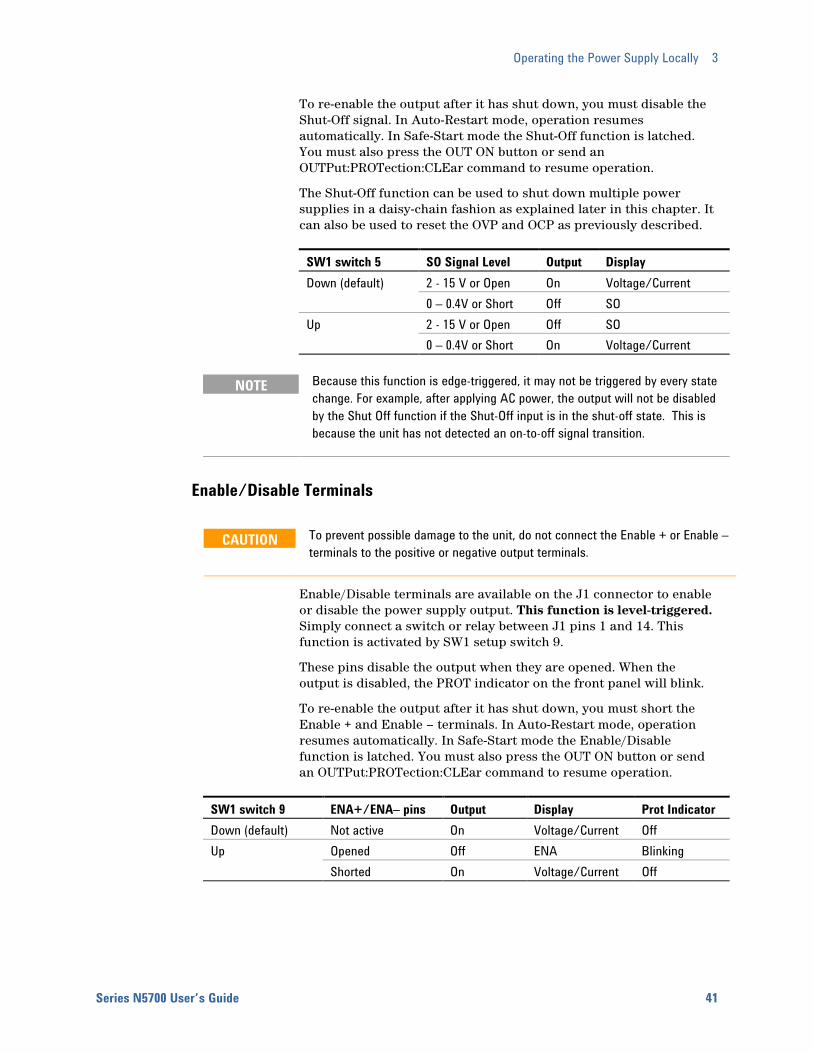
To re-enable the output after it has shut down, you must disable the Shut-Off signal. In Auto-Restart mode, operation resumes automatically. In Safe-Start mode the Shut-Off function is latched. You must also press the OUT ON button or send an OUTPut:PROTection:CLEar command to resume operation.
The Shut-Off function can be used to shut down multiple power supplies in a daisy-chain fashion as explained later in this chapter. It can also be used to reset the OVP and OCP as previously described.
SW1 switch 5 SO Signal Level Output Display Down (default) 2 - 15 V or Open On Voltage/Current 0 – 0.4V or Short Off SO Up 2 - 15 V or Open Off SO 0 – 0.4V or Short On Voltage/Current
NOTE Because this function is edge-triggered, it may not be triggered by every state change. For example, after applying AC power, the output will not be disabled by the Shut Off function if the Shut-Off input is in the shut-off state. This is because the unit has not detected an on-to-off signal transition.
Enable/Disable Terminals
CAUTION To prevent possible damage to the unit, do not connect the Enable + or Enable – terminals to the positive or negative output terminals.
Enable/Disable terminals are available on the J1 connector to enable or disable the power supply output. This function is level-triggered. Simply connect a switch or relay between J1 pins 1 and 14. This function is activated by SW1 setup switch 9.
These pins disable the output when they are opened. When the output is disabled, the PROT indicator on the front panel will blink.
To re-enable the output after it has shut down, you must short the Enable + and Enable – terminals. In Auto-Restart mode, operation resumes automatically. In Safe-Start mode the Enable/Disable function is latched. You must also press the OUT ON button or send an OUTPut:PROTection:CLEar command to resume operation.
SW1 switch 9 ENA+/ENA– pins Output Display Prot Indicator Down (default) Not active On Voltage/Current Off Up Opened Off ENA Blinking Shorted On Voltage/Current Off

3 Operating the Power Supply Locally
42 Series N5700 User’s Guide
Power Supply OK Signal The Power Supply OK signal on the J1 connector indicates a fault condition in the power supply. J1 pin 16 is a TTL output signal. Pins 2 and 3, which are connected internally, are the signal common. All pins are optically isolated from the power supply output. With no fault, Power Supply OK is high, with a maximum source current of 2mA. When a fault occurs, Power Supply OK is low, with a maximum sink current of 1mA. The following faults set this signal low:
Over-voltage protection Enable/Disable signal true
Over-current protection Shut Off signal true
Over-temperature protection Remote interface failure
AC line failure Output turned off
Daisy-Chained Output Shut-down It is possible to configure a multiple power supply system to shut down all the units when a fault condition occurs in one of the units. SW1 setup switch 5 must be in the Down position to enable the daisy-chain operation. Other switches are unaffected by this setting.
If a fault occurs in one unit, its Power Supply OK signal is set low and its display will indicate the fault. The other units shut off with their displays indicating SO. When the fault condition is cleared, all units will recover according to their Safe-Start or Auto-Restart settings.
The following figure shows three units daisy-chained - the same connection method can be used with additional units. The Shut Off and Power Supply OK signals are referenced to Chassis Common (J1 pins 2 and 3).
Analog Programming of Output Voltage and Current
CAUTION J1 pin 12, pin 22, and pin 23 are internally connected to the negative sense terminal. Do not reference these pins to any terminal other than the negative sense terminal, as it may damage the unit.
In Local mode, the output voltage and current is programmed with the front panel VOLTAGE and CURRENT knobs or over the remote interface. In Analog mode, the output voltage and current can be programmed either by an analog voltage or by resistors connected to the rear panel J1 connector.
POWER SUPPLY
#1J1-2,3 J1-16 J1-16J1-16J1-15
Supply OK
POWER SUPPLY
#2J1-2,3 J1-15
POWER SUPPLY#3
J1-2,3 J1-15
Shut OffCom Shut OffSupply OKCom Com Supply OK Shut Off
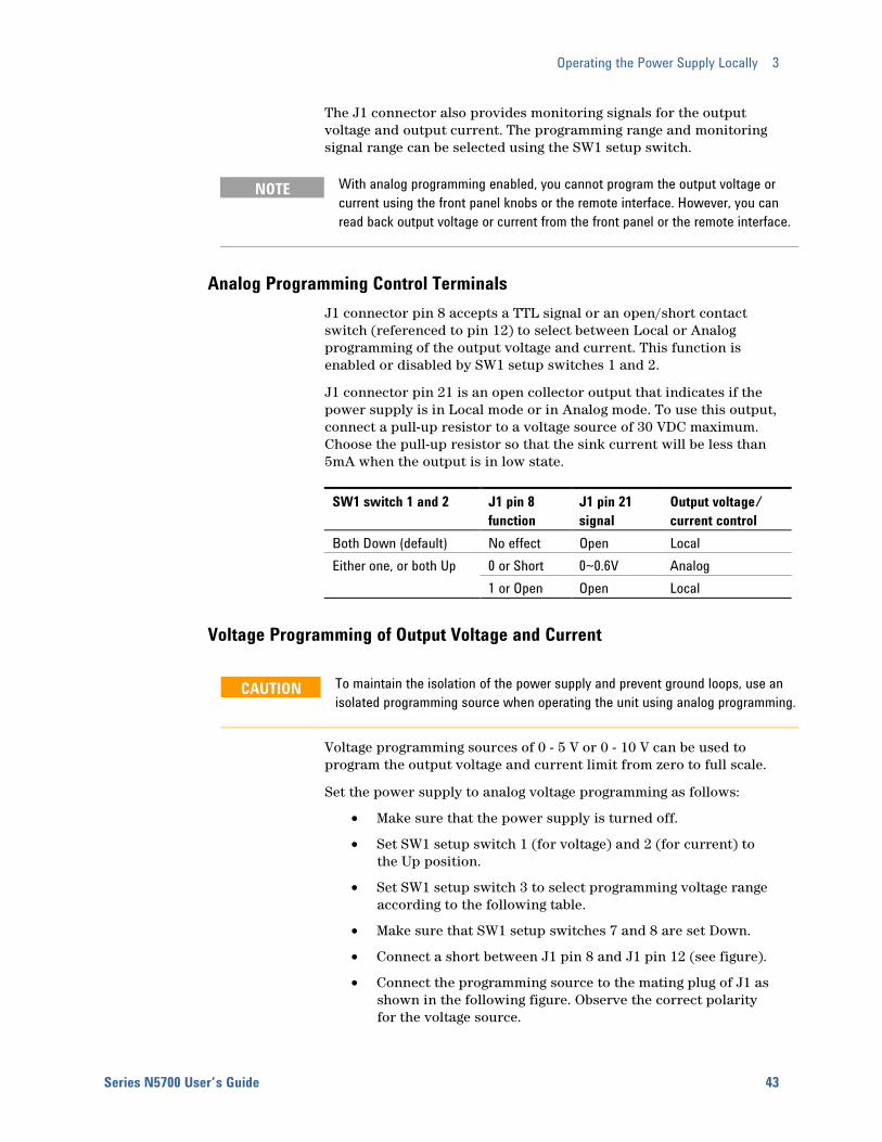
Operating the Power Supply Locally 3
Series N5700 User’s Guide 43
The J1 connector also provides monitoring signals for the output voltage and output current. The programming range and monitoring signal range can be selected using the SW1 setup switch.
NOTE With analog programming enabled, you cannot program the output voltage or current using the front panel knobs or the remote interface. However, you can read back output voltage or current from the front panel or the remote interface.
Analog Programming Control Terminals J1 connector pin 8 accepts a TTL signal or an open/short contact switch (referenced to pin 12) to select between Local or Analog programming of the output voltage and current. This function is enabled or disabled by SW1 setup switches 1 and 2.
J1 connector pin 21 is an open collector output that indicates if the power supply is in Local mode or in Analog mode. To use this output, connect a pull-up resistor to a voltage source of 30 VDC maximum. Choose the pull-up resistor so that the sink current will be less than 5mA when the output is in low state.
SW1 switch 1 and 2 J1 pin 8 function
J1 pin 21 signal
Output voltage/ current control
Both Down (default) No effect Open Local Either one, or both Up 0 or Short 0~0.6V Analog 1 or Open Open Local
Voltage Programming of Output Voltage and Current
CAUTION To maintain the isolation of the power supply and prevent ground loops, use an isolated programming source when operating the unit using analog programming.
Voltage programming sources of 0 - 5 V or 0 - 10 V can be used to program the output voltage and current limit from zero to full scale.
Set the power supply to analog voltage programming as follows:
• Make sure that the power supply is turned off.
• Set SW1 setup switch 1 (for voltage) and 2 (for current) to the Up position.
• Set SW1 setup switch 3 to select programming voltage range according to the following table.
• Make sure that SW1 setup switches 7 and 8 are set Down.
• Connect a short between J1 pin 8 and J1 pin 12 (see figure).
• Connect the programming source to the mating plug of J1 as shown in the following figure. Observe the correct polarity for the voltage source.
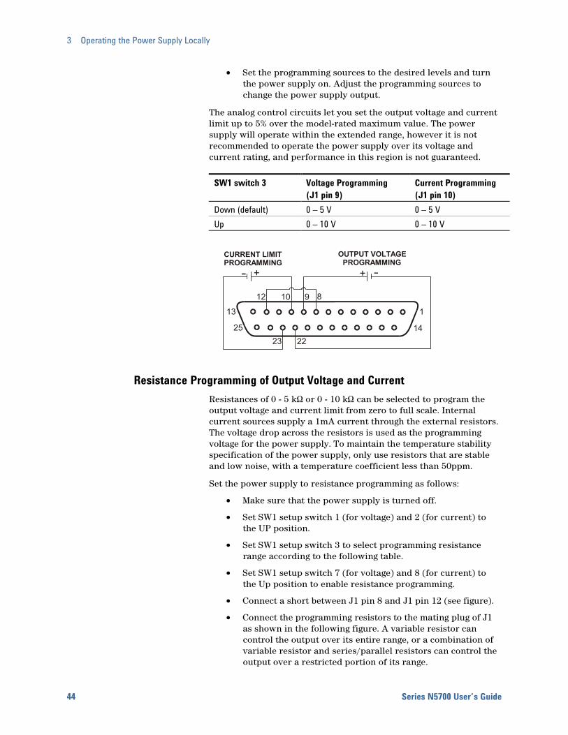
3 Operating the Power Supply Locally
44 Series N5700 User’s Guide
• Set the programming sources to the desired levels and turn the power supply on. Adjust the programming sources to change the power supply output.
The analog control circuits let you set the output voltage and current limit up to 5% over the model-rated maximum value. The power supply will operate within the extended range, however it is not recommended to operate the power supply over its voltage and current rating, and performance in this region is not guaranteed.
SW1 switch 3 Voltage Programming (J1 pin 9)
Current Programming (J1 pin 10)
Down (default) 0 – 5 V 0 – 5 V Up 0 – 10 V 0 – 10 V
Resistance Programming of Output Voltage and Current Resistances of 0 - 5 kΩ or 0 - 10 kΩ can be selected to program the output voltage and current limit from zero to full scale. Internal current sources supply a 1mA current through the external resistors. The voltage drop across the resistors is used as the programming voltage for the power supply. To maintain the temperature stability specification of the power supply, only use resistors that are stable and low noise, with a temperature coefficient less than 50ppm.
Set the power supply to resistance programming as follows:
• Make sure that the power supply is turned off.
• Set SW1 setup switch 1 (for voltage) and 2 (for current) to the UP position.
• Set SW1 setup switch 3 to select programming resistance range according to the following table.
• Set SW1 setup switch 7 (for voltage) and 8 (for current) to the Up position to enable resistance programming.
• Connect a short between J1 pin 8 and J1 pin 12 (see figure).
• Connect the programming resistors to the mating plug of J1 as shown in the following figure. A variable resistor can control the output over its entire range, or a combination of variable resistor and series/parallel resistors can control the output over a restricted portion of its range.
1
14
13
25
1012 89
23 22
+ +
CURRENT LIMITPROGRAMMING
OUTPUT VOLTAGEPROGRAMMING
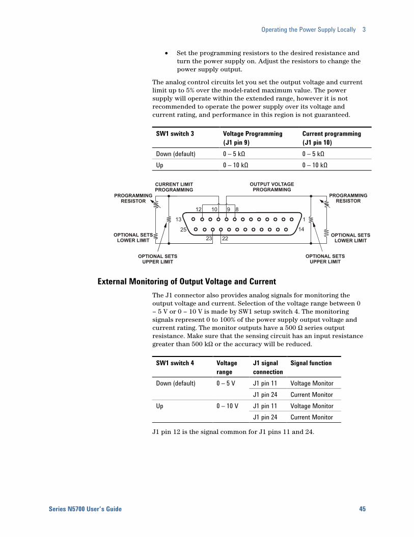
Operating the Power Supply Locally 3
Series N5700 User’s Guide 45
• Set the programming resistors to the desired resistance and turn the power supply on. Adjust the resistors to change the power supply output.
The analog control circuits let you set the output voltage and current limit up to 5% over the model-rated maximum value. The power supply will operate within the extended range, however it is not recommended to operate the power supply over its voltage and current rating, and performance in this region is not guaranteed.
SW1 switch 3 Voltage Programming (J1 pin 9)
Current programming (J1 pin 10)
Down (default) 0 – 5 kΩ 0 – 5 kΩ Up 0 – 10 kΩ 0 – 10 kΩ
External Monitoring of Output Voltage and Current The J1 connector also provides analog signals for monitoring the output voltage and current. Selection of the voltage range between 0 – 5 V or 0 – 10 V is made by SW1 setup switch 4. The monitoring signals represent 0 to 100% of the power supply output voltage and current rating. The monitor outputs have a 500 Ω series output resistance. Make sure that the sensing circuit has an input resistance greater than 500 kΩ or the accuracy will be reduced.
SW1 switch 4 Voltage range
J1 signal connection
Signal function
Down (default) 0 – 5 V J1 pin 11 Voltage Monitor J1 pin 24 Current Monitor Up 0 – 10 V J1 pin 11 Voltage Monitor J1 pin 24 Current Monitor
J1 pin 12 is the signal common for J1 pins 11 and 24.
1
14
13
25
10 9
23 22
CURRENT LIMITPROGRAMMING
OUTPUT VOLTAGEPROGRAMMING
PROGRAMMING RESISTOR
PROGRAMMING RESISTOR
OPTIONAL SETSLOWER LIMIT
OPTIONAL SETSLOWER LIMIT
OPTIONAL SETSUPPER LIMIT
OPTIONAL SETSUPPER LIMIT
12 8


Series N5700 User’s Guide 47
4 Operating the Power Supply Remotely Connecting to the Interfaces .......................................................................... 48 SCPI Commands – an Introduction................................................................ 58
This chapter contains information on how to configure the three remote interfaces that are provided on the back of the instrument. In most cases you can connect your power supply to any one of these interfaces and be up and running with a minimum amount of configuration.
NOTE Detailed information on configuring the remote interfaces is included in the USB/LAN/GPIB Interfaces Connectivity Guide document located on the Automation-Ready CD-ROM included with this product.
This chapter also contains a brief introduction to the SCPI Programming language. SCPI (Standard Commands for Programmable Instruments) is a programming language for controlling instrument functions over the GPIB. SCPI is layered on top of the hardware-portion of IEEE 488.2. The same SCPI commands and parameters control the same functions in different classes of instruments.
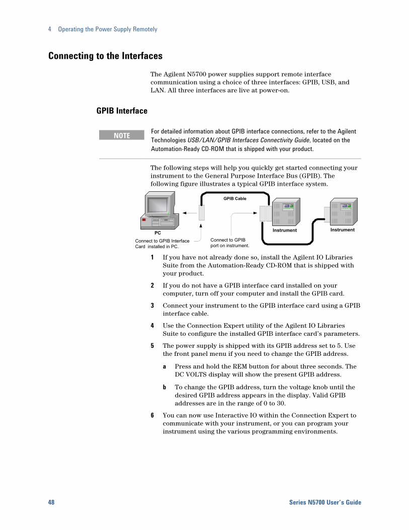
4 Operating the Power Supply Remotely
48 Series N5700 User’s Guide
Connecting to the Interfaces The Agilent N5700 power supplies support remote interface communication using a choice of three interfaces: GPIB, USB, and LAN. All three interfaces are live at power-on.
GPIB Interface
NOTE For detailed information about GPIB interface connections, refer to the Agilent Technologies USB/LAN/GPIB Interfaces Connectivity Guide, located on the Automation-Ready CD-ROM that is shipped with your product.
The following steps will help you quickly get started connecting your instrument to the General Purpose Interface Bus (GPIB). The following figure illustrates a typical GPIB interface system.
1 If you have not already done so, install the Agilent IO Libraries Suite from the Automation-Ready CD-ROM that is shipped with your product.
2 If you do not have a GPIB interface card installed on your computer, turn off your computer and install the GPIB card.
3 Connect your instrument to the GPIB interface card using a GPIB interface cable.
4 Use the Connection Expert utility of the Agilent IO Libraries Suite to configure the installed GPIB interface card’s parameters.
5 The power supply is shipped with its GPIB address set to 5. Use the front panel menu if you need to change the GPIB address.
a Press and hold the REM button for about three seconds. The DC VOLTS display will show the present GPIB address.
b To change the GPIB address, turn the voltage knob until the desired GPIB address appears in the display. Valid GPIB addresses are in the range of 0 to 30.
6 You can now use Interactive IO within the Connection Expert to communicate with your instrument, or you can program your instrument using the various programming environments.
PC Instrument
GPIB Cable
Connect to GPIB InterfaceCard installed in PC.
Instrument
Connect to GPIBport on instrument.

Operating the Power Supply Remotely 4
Series N5700 User’s Guide 49
USB Interface
NOTE For detailed information about USB interface connections, refer to the Agilent Technologies USB/LAN/GPIB Interfaces Connectivity Guide, located on the Automation-Ready CD-ROM that is shipped with your product.
The following steps will help you quickly get started connecting your USB-enabled instrument to the Universal Serial Bus (USB). The following figure illustrates a typical USB interface system.
1 If you have not already done so, install the Agilent IO Libraries Suite from the Automation-Ready CD-ROM that is shipped with your product.
2 Connect your instrument to the USB port on your computer.
3 With the Connection Expert utility of the Agilent IO Libraries Suite running, the computer will automatically recognize the instrument. This may take several seconds. When the instrument is recognized, your computer will display the VISA alias, IDN string, and VISA address. This information is located in the USB folder.
NOTE The VISA address is: USB0::2391::2055::serialnumber::0:INSTR where 2391 is the Agilent code, 2055 is the N5700 code, and serialnumber is the 10-character serial number located on the label on the side of the unit.
4 You can now use Interactive IO within the Connection Expert to communicate with your instrument, or you can program your instrument using the various programming environments.
LAN Interface
NOTE For detailed information about LAN interface connections, refer to the Agilent Technologies USB/LAN/GPIB Interfaces Connectivity Guide, located on the Automation-Ready CD-ROM that is shipped with your product.
The following steps will help you quickly get started connecting and configuring your instrument on a local area network (LAN). The two types of local area networks connections that are discussed in this section are site networks and private networks.
PC Instrument
USB Cable
Connect to USBport on PC.
Connect toUSB port oninstrument.
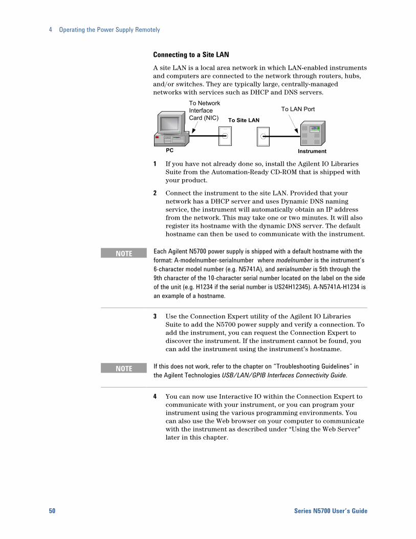
4 Operating the Power Supply Remotely
50 Series N5700 User’s Guide
Connecting to a Site LAN A site LAN is a local area network in which LAN-enabled instruments and computers are connected to the network through routers, hubs, and/or switches. They are typically large, centrally-managed networks with services such as DHCP and DNS servers.
1 If you have not already done so, install the Agilent IO Libraries Suite from the Automation-Ready CD-ROM that is shipped with your product.
2 Connect the instrument to the site LAN. Provided that your network has a DHCP server and uses Dynamic DNS naming service, the instrument will automatically obtain an IP address from the network. This may take one or two minutes. It will also register its hostname with the dynamic DNS server. The default hostname can then be used to communicate with the instrument.
NOTE Each Agilent N5700 power supply is shipped with a default hostname with the format: A-modelnumber-serialnumber where modelnumber is the instrument’s 6-character model number (e.g. N5741A), and serialnumber is 5th through the 9th character of the 10-character serial number located on the label on the side of the unit (e.g. H1234 if the serial number is US24H12345). A-N5741A-H1234 is an example of a hostname.
3 Use the Connection Expert utility of the Agilent IO Libraries Suite to add the N5700 power supply and verify a connection. To add the instrument, you can request the Connection Expert to discover the instrument. If the instrument cannot be found, you can add the instrument using the instrument’s hostname.
NOTE If this does not work, refer to the chapter on “Troubleshooting Guidelines” in the Agilent Technologies USB/LAN/GPIB Interfaces Connectivity Guide.
4 You can now use Interactive IO within the Connection Expert to communicate with your instrument, or you can program your instrument using the various programming environments. You can also use the Web browser on your computer to communicate with the instrument as described under “Using the Web Server” later in this chapter.
PC Instrument
To Site LAN
To NetworkInterfaceCard (NIC)
To LAN Port
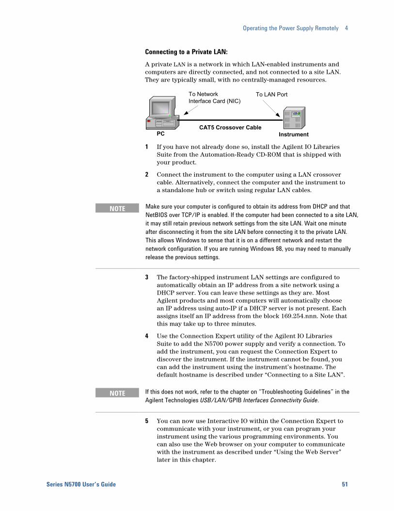
Operating the Power Supply Remotely 4
Series N5700 User’s Guide 51
Connecting to a Private LAN: A private LAN is a network in which LAN-enabled instruments and computers are directly connected, and not connected to a site LAN. They are typically small, with no centrally-managed resources.
1 If you have not already done so, install the Agilent IO Libraries Suite from the Automation-Ready CD-ROM that is shipped with your product.
2 Connect the instrument to the computer using a LAN crossover cable. Alternatively, connect the computer and the instrument to a standalone hub or switch using regular LAN cables.
NOTE Make sure your computer is configured to obtain its address from DHCP and that NetBIOS over TCP/IP is enabled. If the computer had been connected to a site LAN, it may still retain previous network settings from the site LAN. Wait one minute after disconnecting it from the site LAN before connecting it to the private LAN. This allows Windows to sense that it is on a different network and restart the network configuration. If you are running Windows 98, you may need to manually release the previous settings.
3 The factory-shipped instrument LAN settings are configured to automatically obtain an IP address from a site network using a DHCP server. You can leave these settings as they are. Most Agilent products and most computers will automatically choose an IP address using auto-IP if a DHCP server is not present. Each assigns itself an IP address from the block 169.254.nnn. Note that this may take up to three minutes.
4 Use the Connection Expert utility of the Agilent IO Libraries Suite to add the N5700 power supply and verify a connection. To add the instrument, you can request the Connection Expert to discover the instrument. If the instrument cannot be found, you can add the instrument using the instrument’s hostname. The default hostname is described under “Connecting to a Site LAN”.
NOTE If this does not work, refer to the chapter on “Troubleshooting Guidelines” in the Agilent Technologies USB/LAN/GPIB Interfaces Connectivity Guide.
5 You can now use Interactive IO within the Connection Expert to communicate with your instrument, or you can program your instrument using the various programming environments. You can also use the Web browser on your computer to communicate with the instrument as described under “Using the Web Server” later in this chapter.
CAT5 Crossover CablePC Instrument
To NetworkInterface Card (NIC)
To LAN Port
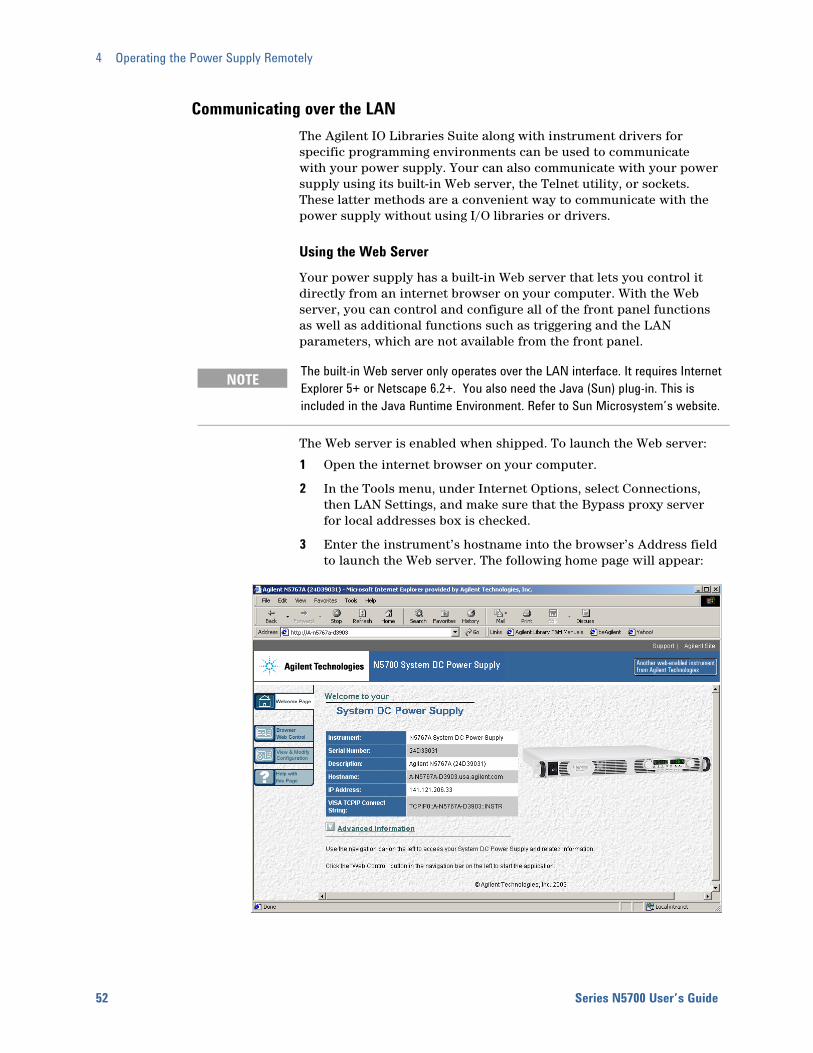
4 Operating the Power Supply Remotely
52 Series N5700 User’s Guide
Communicating over the LAN The Agilent IO Libraries Suite along with instrument drivers for specific programming environments can be used to communicate with your power supply. Your can also communicate with your power supply using its built-in Web server, the Telnet utility, or sockets. These latter methods are a convenient way to communicate with the power supply without using I/O libraries or drivers.
Using the Web Server Your power supply has a built-in Web server that lets you control it directly from an internet browser on your computer. With the Web server, you can control and configure all of the front panel functions as well as additional functions such as triggering and the LAN parameters, which are not available from the front panel.
NOTE The built-in Web server only operates over the LAN interface. It requires Internet Explorer 5+ or Netscape 6.2+. You also need the Java (Sun) plug-in. This is included in the Java Runtime Environment. Refer to Sun Microsystem’s website.
The Web server is enabled when shipped. To launch the Web server:
1 Open the internet browser on your computer.
2 In the Tools menu, under Internet Options, select Connections, then LAN Settings, and make sure that the Bypass proxy server for local addresses box is checked.
3 Enter the instrument’s hostname into the browser’s Address field to launch the Web server. The following home page will appear:

Operating the Power Supply Remotely 4
Series N5700 User’s Guide 53
4 Click on the Browser Web Control button in the navigation bar on the left to begin controlling your instrument.
5 For additional help about any of the pages, click on the Help with this Page button.
Using Telnet In an MS-DOS Command Prompt box type: telnet hostname 5024 where hostname is the N5700 hostname or IP address, and 5024 is the instrument’s telnet port.
You should get a Telnet session box with a title indicating that you are connected to the power supply. Type the SCPI commands at the prompt.
Using Sockets Agilent instruments have standardized on using port 5025 for SCPI socket services. A data socket on this port can be used to send and receive ASCII/SCPI commands, queries, and query responses. All commands must be terminated with a newline for the message to be parsed. All query responses will also be terminated with a newline. The power supply allows any combination of up to three simultaneous data socket and telnet connections to be made.
The socket programming interface also allows a control socket connection. The control socket can be used by a client to send device clear and to receive service requests. Unlike the data socket, which uses a fixed port number, the port number for a control socket varies and must be obtained by sending the following SCPI query to the data socket: SYSTem:COMMunicate:TCPip:CONTrol?
After the control port number is obtained, a control socket connection can be opened. As with the data socket, all commands to the control socket must be terminated with a newline, and all query responses returned on the control socket will be terminated with a newline.
To send a device clear, send the string “DCL” to the control socket. When the power supply has finished performing the device clear it echoes the string “DCL” back to the control socket.
Service requests are enabled for control sockets using the Service Request Enable register. Once service requests have been enabled, the client program listens on the control connection. When SRQ goes true the instrument will send the string “SRQ +nn” to the client. The “nn” is the status byte value, which the client can use to determine the source of the service request.
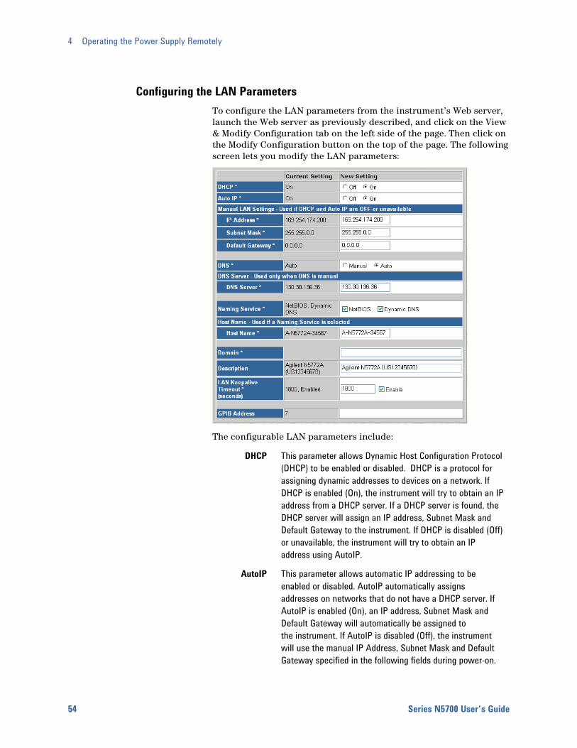
4 Operating the Power Supply Remotely
54 Series N5700 User’s Guide
Configuring the LAN Parameters To configure the LAN parameters from the instrument’s Web server, launch the Web server as previously described, and click on the View & Modify Configuration tab on the left side of the page. Then click on the Modify Configuration button on the top of the page. The following screen lets you modify the LAN parameters:
The configurable LAN parameters include:
DHCP This parameter allows Dynamic Host Configuration Protocol (DHCP) to be enabled or disabled. DHCP is a protocol for assigning dynamic addresses to devices on a network. If DHCP is enabled (On), the instrument will try to obtain an IP address from a DHCP server. If a DHCP server is found, the DHCP server will assign an IP address, Subnet Mask and Default Gateway to the instrument. If DHCP is disabled (Off) or unavailable, the instrument will try to obtain an IP address using AutoIP.
AutoIP This parameter allows automatic IP addressing to be enabled or disabled. AutoIP automatically assigns addresses on networks that do not have a DHCP server. If AutoIP is enabled (On), an IP address, Subnet Mask and Default Gateway will automatically be assigned to the instrument. If AutoIP is disabled (Off), the instrument will use the manual IP Address, Subnet Mask and Default Gateway specified in the following fields during power-on.
Operating the Power Supply Remotely 4
Series N5700 User’s Guide 55
IP Address This value is the Internet Protocol (IP) address of the instrument. An IP address is required for all IP and TCP/IP communications with the instrument. An IP Address consists of 4 decimal numbers separated by periods. Each decimal number ranges from 0 through 255. If the IP Address is changed, the instrument must be rebooted for this change to be effective. Factory setting = 169.254.57.0
Subnet Mask
This value is used to enable the instrument to determine if a client IP address is on the same local subnet. When a client IP address is on a different subnet, all packets must be sent to the Default Gateway. If the Subnet Mask is changed, the instrument must be rebooted for this change to be effective. Factory setting = 255.255.255.0
Default Gateway
This value is the IP Address of the default gateway that allows the instrument to communicate with systems that are not on the local subnet, as determined by the subnet mask setting. If the Default Gateway is changed, the instrument must be rebooted for this change to be effective. Factory setting = 0.0.0.0, which indicates that no default gateway is defined.
DNS DNS is an internet service that translates domain names into IP addresses. This parameter indicates whether the IP address of the Domain Name System (DNS) server is obtained automatically or manually. If the parameter is set to Auto, the DNS server address is obtained from DHCP. If the parameter is set to Manual, the DNS server in the following field is used.
DNS Server This value is the address of the Domain Name System (DNS) server. If DHCP is disabled, the DNS server parameter is needed for the instrument to be able to find and display its hostname.
Naming service
This parameter specifies the Naming service, if any, to be used to register the instrument. NetBIOS indicates the instrument will be registered using the RFC NetBIOS naming protocol. Dynamic DNS indicates the instrument will be registered using the Dynamic DNS naming system.
Hostname This field registers the supplied name with the selected naming service. If the field is left blank, then no name is registered. A hostname may contain upper and lower case letters, numbers and dashes(-). The maximum length is 15 characters. The factory default is A-modelnumber-serialnumber. Modelnumber is the instrument’s 6-character model number, and serialnumber is 5th through the 9th character of the 10-character serial number located on the label on the side of the unit.

4 Operating the Power Supply Remotely
56 Series N5700 User’s Guide
Domain This field registers the Internet domain for the instrument. The Domain must start with a letter and may contain upper and lower case letters, numbers, dashes(-) and dots(.).
Description This field lets you assign a user-friendly name to the instrument. This name is used as the title of the instrument home page.
LAN Keepalive
Timeout
This value sets the LAN keepalive in seconds. The instrument uses the TCP keepalive timer to determine if a client is still reachable. If after the specified amount of time, there has been no activity on the connection, the instrument will send keepalive probes to the client to determine if it is still alive. If not, the connection will be marked as down or "dropped." The instrument will release any resources that were allocated to that client. When this parameter is set, it is recommended that the largest value be used that still meets the application's need for unreachable client detection. Smaller keepalive timeout values will generate more keepalive probes (network traffic), using more of the available network bandwidth. Check the Enable box to enable the Lan Keepalive function. Allowed values: 720 - 99999 seconds.
Using the Setup Utility A Setup Utility that lets you configure the LAN settings of your instrument is provided on the Product Reference CD-ROM included with this manual. Install and run this Setup Utility if you cannot configure the LAN interface as previously described in this section.
1 Connect your power supply to your computer using either a USB a GPIB interface as previously described.
2 Install the Setup utility from the CD-ROM onto your computer. Run the Setup utility be clicking on its icon.
3 Select the interface you are using. Click on the Connections tab and select either USB or GPIB.
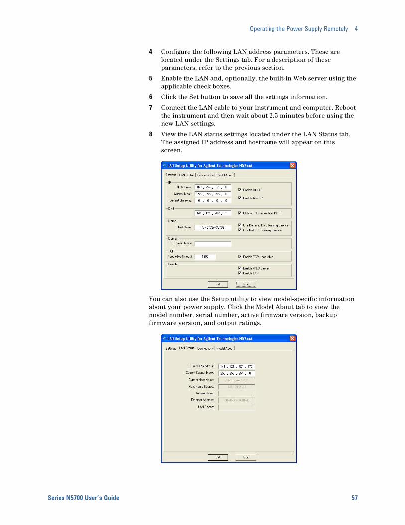
Operating the Power Supply Remotely 4
Series N5700 User’s Guide 57
4 Configure the following LAN address parameters. These are located under the Settings tab. For a description of these parameters, refer to the previous section.
5 Enable the LAN and, optionally, the built-in Web server using the applicable check boxes.
6 Click the Set button to save all the settings information.
7 Connect the LAN cable to your instrument and computer. Reboot the instrument and then wait about 2.5 minutes before using the new LAN settings.
8 View the LAN status settings located under the LAN Status tab. The assigned IP address and hostname will appear on this screen.
You can also use the Setup utility to view model-specific information about your power supply. Click the Model About tab to view the model number, serial number, active firmware version, backup firmware version, and output ratings.
4 Operating the Power Supply Remotely
58 Series N5700 User’s Guide
SCPI Commands – an Introduction SCPI (Standard Commands for Programmable Instruments) is an ASCII-based instrument command language designed for test and measurement instruments. SCPI commands are based on a hierarchical structure, also known as a tree system. In this system, associated commands are grouped together under a common node or root, thus forming subsystems. Subsystem commands perform specific power supply functions. A portion of the SOURce subsystem is shown below to illustrate the tree system.
[SOURce:] CURRent [:LEVel] [:IMMediate] <NRf+> :TRIGgered <NRf+> :PROTection :STATe <Bool>
SOURce is the root keyword of the command, CURRent is a second-level keyword, LEVel and PROTection are third-level keywords, and IMMediate, TRIGgered and STATe are fourth-level keywords. Colons (:) separate higher-level from lower-level keywords.
Syntax The following command syntax is used in this manual:
Square Brackets [ ] Items within square brackets are optional. The representation [SOURce:]VOLTage means that SOURce: may be omitted.
Angle brackets < > Items within angle brackets are parameter descriptions. For example, <NR1> indicates a specific form of numerical data.
Vertical bar | Vertical bars separate alternative parameters. For example, VOLT | CURR indicates that either "VOLT" or "CURR" can be used as a parameter.
The syntax characters cannot be included in the command string.
Multiple Commands in a Message Multiple SCPI commands can be combined and sent as a single message with one message terminator. There are two important considerations when sending several commands within a single message:
Use a semicolon (;) to separate commands within a message.
There is an implied path that affects how commands are interpreted by the power supply.
The command path can be thought of as a string that gets inserted before each keyword within a message. For the first command in a message, the path is a null string. For each subsequent command the path is defined as the characters that make up the keywords of the
Operating the Power Supply Remotely 4
Series N5700 User’s Guide 59
previous command in the message up to and including the last colon separator. An example of a message with two commands is:
OUTPut:STATe ON;PROTection:CLEar
which shows the use of the semicolon separating the two commands, and also illustrates the command path concept. Note that with the second command, the leading keyword OUTPut was omitted because after the OUTPut:STATe ON command, the path became defined as OUTPut, and thus the second command was interpreted as:
OUTPut:PROTection:CLEar
In fact, it would have been incorrect to include the OUTPut keyword in the second command, because the result after combining it with the command path would be:
OUTPut:OUTPut:PROTection:CLEar
which would result in a syntax error.
Commands from Different Subsystems In order to combine commands from different subsystems, you need to be able to reset the command path to a null string within a message. Beginning the command with a colon (:), discards the previous path. For example, you could clear the output protection and check the status of the Operation Condition register in one message by using a root specifier as follows:
OUTPut:PROTection:CLEar;:STATus:OPERation:CONDition?
The following message shows how to combine commands from different subsystems as well as within the same subsystem.
VOLTage:LEVel 7.5;PROTection 10;:CURRent:LEVel 0.25
Note the use of the optional keyword LEVel to maintain the correct path within the subsystems, and the use of the root specifier (:) to move between subsystems.
Message Unit The simplest SCPI command is a single message unit consisting of a keyword followed by a message terminator such as newline. The message unit may include a parameter after the keyword. The parameter can be numeric or a string.
ABORt<NL>
VOLTage 20<NL>
VOLTage:TRIGgered MINimum<NL>
Colons (:) separate higher-level keywords from lower-level keywords. Use a blank space to separate parameters from keywords. If a command requires more than one parameter, use commas to separate adjacent parameters.

4 Operating the Power Supply Remotely
60 Series N5700 User’s Guide
In the previous examples, the upper-case letters indicate the abbreviated spelling for the keyword. For shorter program lines, you can send the abbreviated form. For better program readability, you can send the long form. For example, VOLT and VOLTage are both acceptable forms. You can use upper- or lower-case letters. Therefore, VOLTAGE, Volt, and volt are all acceptable. Other forms, such as VOL and VOLTAG, generate an error.
Queries You can query the current value of most commands by adding a question mark to the command (VOLTage?, VOLTage:TRIGgered?). If a query contains a parameter, place the query indicator at the end of the last keyword. Observe the following precautions with queries:
Add a blank space between the query indicator (?) and any subsequent parameter. (VOLTage:TRIGgered? MAX)
Set up the proper number of variables for the returned data.
Read back all the results of a query before sending another command to the power supply. Otherwise a Query Interrupted error will occur and the unreturned data will be lost.
Common Commands Common commands generally control overall power supply functions, such as reset, status, and synchronization. All common commands consist of a three-letter mnemonic preceded by an asterisk: *RST *IDN? *SRE 8
You can combine common commands with subsystem commands in the same message. Use semicolons to separate the common command from the subsystem commands. Common commands do not affect the command path; you may insert them anywhere in the message.
VOLTage:TRIGgered 10;:INITiate;*TRG
OUTPut OFF;*RCL 2;OUTPut ON
Command Terminators A terminator informs SCPI that it has reached the end of a command. Three permitted command terminators are:
newline (<NL>), which is ASCII decimal 10 or hex 0A.
end or identify (<END>)
both of the above (<NL><END>).
In the examples of this guide, the message terminator is assumed.
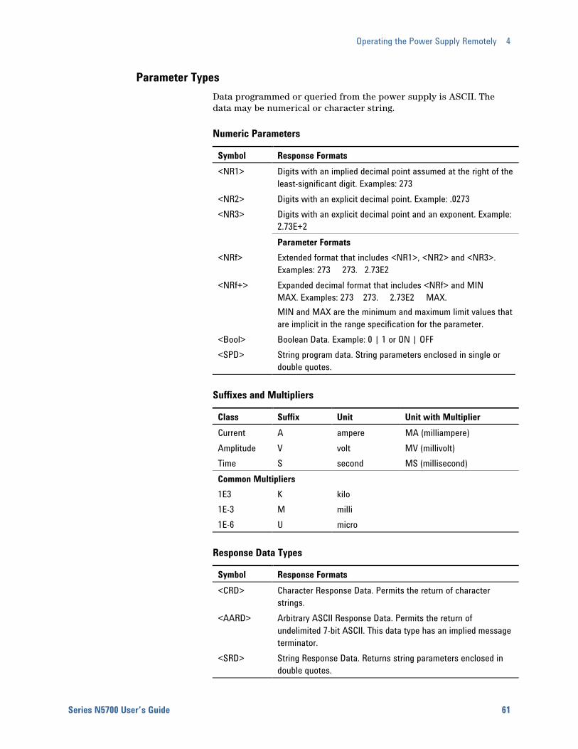
Operating the Power Supply Remotely 4
Series N5700 User’s Guide 61
Parameter Types Data programmed or queried from the power supply is ASCII. The data may be numerical or character string.
Numeric Parameters
Symbol Response Formats <NR1> Digits with an implied decimal point assumed at the right of the
least-significant digit. Examples: 273 <NR2> Digits with an explicit decimal point. Example: .0273 <NR3> Digits with an explicit decimal point and an exponent. Example:
2.73E+2 Parameter Formats <NRf> Extended format that includes <NR1>, <NR2> and <NR3>.
Examples: 273 273. 2.73E2 <NRf+> Expanded decimal format that includes <NRf> and MIN
MAX. Examples: 273 273. 2.73E2 MAX. MIN and MAX are the minimum and maximum limit values that are implicit in the range specification for the parameter.
<Bool> Boolean Data. Example: 0 | 1 or ON | OFF <SPD> String program data. String parameters enclosed in single or
double quotes.
Suffixes and Multipliers
Class Suffix Unit Unit with Multiplier Current A ampere MA (milliampere) Amplitude V volt MV (millivolt) Time S second MS (millisecond) Common Multipliers 1E3 K kilo 1E-3 M milli 1E-6 U micro
Response Data Types
Symbol Response Formats <CRD> Character Response Data. Permits the return of character
strings. <AARD> Arbitrary ASCII Response Data. Permits the return of
undelimited 7-bit ASCII. This data type has an implied message terminator.
<SRD> String Response Data. Returns string parameters enclosed in double quotes.
4 Operating the Power Supply Remotely
62 Series N5700 User’s Guide
SCPI Command Completion SCPI commands sent to the power system are processed either sequentially or in parallel. Sequential commands finish execution before a subsequent command begins. Parallel commands allow other commands to begin executing while the parallel command is still executing.
The following is a list of parallel commands. You should use some form of command synchronization as discussed in this section before assuming that these commands have completed. OUTPut:STATe INITiate VOLTage OUTPut:PROTection:CLEar CURRent
The *WAI, *OPC, and *OPC? common commands provide different ways of indicating when all transmitted commands, including any parallel ones, have completed their operations. Some practical considerations for using these commands are as follows:
*WAI This command prevents the power system from processing subsequent commands until all pending operations are completed. For example, the *WAI command can be used to make a current measurement after an output on command has completed:
OUTPut ON;*WAI;:MEASure:CURRent?
*OPC? This command places a 1 in the Output Queue when all pending operations have completed. Because it requires your program to read the returned value before executing the next program statement, *OPC? can be used to cause the controller to wait for commands to complete before proceeding with its program.
*OPC This command sets the OPC status bit when all pending operations have completed. Since your program can read this status bit on an interrupt basis, *OPC allows subsequent commands to be executed.
NOTE The trigger subsystem must be in the Idle state for the status OPC bit to be true. As far as triggers are concerned, OPC is false whenever the trigger subsystem is in the Initiated state.
Device Clear You can send a Device Clear at any time to abort a SCPI command that may be hanging up the GPIB interface. Device Clear clears the input and output buffers of the power supply. The status registers, error queue, and all configuration states are left unchanged by Device Clear. Device Clear also prepares the power supply to accept a new command string. The following statement shows how to send a device clear over the GPIB interface using Agilent BASIC:
CLEAR 705 IEEE-488 Device Clear
Series N5700 User’s Guide 63
5 Language Reference SCPI Command Summary................................................................................ 64 Calibration Commands ..................................................................................... 66 Measure Commands......................................................................................... 67 Output Commands ............................................................................................ 68 Source Commands............................................................................................ 69 Status Commands............................................................................................. 71 System Commands ........................................................................................... 77 Trigger Commands............................................................................................ 79
This section gives the syntax and parameters for all the IEEE 488.2 SCPI Subsystem commands and Common commands used by the power supply. It is assumed that you are familiar with the material in chapter 4, which explains the terms, symbols, and syntactical structures used here and gives an introduction to programming. You should also be familiar with chapter 3, in order to understand how the power supply functions.
Subsystem commands are specific to functions. They can be a single command or a group of commands. The groups are comprised of commands that extend one or more levels below the root. The subsystem commands are arranged alphabetically according to the function they perform.
Common commands begin with an * and consist of three letters (command) or three letters and a ? (query). They are defined by the IEEE 488.2 standard to perform common interface functions. Common commands are grouped along with the subsystem commands according to the function they perform.
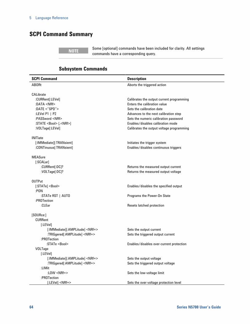
5 Language Reference
64 Series N5700 User’s Guide
SCPI Command Summary
NOTE Some [optional] commands have been included for clarity. All settings commands have a corresponding query.
Subsystem Commands
SCPI Command Description ABORt Aborts the triggered action CALibrate :CURRent[:LEVel] Calibrates the output current programming :DATA <NRf> Enters the calibration value :DATE <”SPD”> Sets the calibration date :LEVel P1 | P2 Advances to the next calibration step :PASSword <NRf> Sets the numeric calibration password :STATE <Bool> [,<NRf>] Enables/disables calibration mode :VOLTage[:LEVel] Calibrates the output voltage programming INITiate [:IMMediate][:TRANsient] Initiates the trigger system :CONTinuous[:TRANsient] Enables/disables continuous triggers MEASure [:SCALar] :CURRent[:DC]? Returns the measured output current :VOLTage[:DC]? Returns the measured output voltage OUTPut [:STATe] <Bool> Enables/disables the specified output :PON :STATe RST | AUTO Programs the Power-On State :PROTection :CLEar Resets latched protection [SOURce:] CURRent [:LEVel] [:IMMediate][:AMPLitude] <NRf+> Sets the output current :TRIGgered[:AMPLitude] <NRf+> Sets the triggered output current :PROTection :STATe <Bool> Enables/disables over-current protection VOLTage [:LEVel] [:IMMediate][:AMPLitude] <NRf+> Sets the output voltage :TRIGgered[:AMPLitude] <NRf+> Sets the triggered output voltage :LIMit :LOW <NRf+> Sets the low-voltage limit :PROTection [:LEVel] <NRf+> Sets the over-voltage protection level

Language Reference 5
Series N5700 User’s Guide 65
SCPI Command Description STATus :OPERation [:EVENt]? Returns the value of the operation event register :CONDition? Returns the value of the operation condition register :ENABle <NRf> Enables specific bits in the Event register :NTRansition<NRf> Sets the Negative transition filter :PTRansition<NRf> Sets the Positive transition filter :PRESet Presets all enable and transition registers to power-on :QUEStionable [:EVENt]? Returns the value of the questionable event register :CONDition? Returns the value of the questionable condition register :ENABle <NRf> Enables specific bits in the Event register :NTRansition<NRf> Sets the Negative transition filter :PTRansition<NRf> Sets the Positive transition filter SYSTem :COMMunicate :RLSTate LOCal | REMote | RWLock Specifies the Remote/Local state of the instrument :ERRor? Returns the error number and error string :VERSion? Returns the SCPI version number TRIGger :SOURce BUS Sets the measurement trigger source [:TRANsient][:IMMediate] Generates a transient trigger
Common Commands
Command Description *CLS Clear status *ESE <NRf> Standard event status enable *ESE? Return standard event status enable *ESR? Return event status register *IDN? Return instrument identification *OPC Enable "operation complete" bit in ESR *OPC? Return a "1" when operation complete *OPT? Return option number *RCL <NRf> Recalls a saved instrument state *RST Reset *SAV <NRf> Saves an instrument state *SRE <NRf> Set service request enable register *SRE? Return service request enable register *STB? Return status byte *TRG Trigger *TST Performs self-test, then returns result *WAI Holds off bus until all device commands done
5 Language Reference
66 Series N5700 User’s Guide
Calibration Commands Calibration commands let you enable and disable the calibration mode, change the calibration password, calibrate current and voltage programming, and store new calibration constants in nonvolatile memory.
NOTE If calibration mode has not been enabled with CALibrate:STATe, the calibration commands will generate an error.
CALibrate:CURRent[:LEVel] <value>
This command initiates the calibration of the output current. The value that you enter selects the range that is being calibrated.
CALibrate:DATA <value>
This command enters a calibration value that you obtain by reading an external meter. You must first select a calibration level (with CALibrate:LEVel) for the value being entered. Data values are entered in either volts or amperes, depending on which function is being calibrated.
CALibrate:DATE <“date”> CALibrate:DATE?
This command stores the date the unit was last calibrated. The data must be of the numeric format “yyyy/mm/dd” where yyyy indicates the year, mm indicates the month, and dd indicates the day. The query returns the date.
CALibrate:LEVel P1|P2
This command selects the next point in the calibration sequence. P1 is the first calibration point, P2 is the second calibration point.
CALibrate:PASSword <password>
This command lets you change the calibration password. A new password is automatically stored in nonvolatile memory. If the password is set to 0, password protection is removed and the ability to enter calibration mode is unrestricted. The default password is 0 (zero).
Language Reference 5
Series N5700 User’s Guide 67
CALibrate:STATe ON|OFF [,<password>] CALibrate:STATe?
This command enables/disables calibration mode. Calibration mode must be enabled for the power supply to accept any other calibration commands. The first parameter specifies the enabled or disabled state On (1) or Off (0). The second parameter is the password.
A password is required if calibration mode is being enabled and the existing password is not 0. If the password is not entered or is incorrect, an error is generated and the calibration mode remains disabled. The query returns only the state, not the password.
The *RST value = Off.
CALibrate:VOLTage[:LEVel] <value>
This command initiates the calibration of the output voltage. The value that you enter selects the range that is being calibrated.
Measure Commands Measure commands measure the output voltage or current. MEASure commands acquire new data before returning the reading. Measurement overflows return a reading of 9.91E+37.
MEASure[:SCALar]:CURRent[:DC]? MEASure[:SCALar]:VOLTage[:DC]?
These queries perform a measurement and return the DC output current in amperes or DC output voltage in volts.
5 Language Reference
68 Series N5700 User’s Guide
Output Commands Output commands enable the output, power-on, and protection functions.
OUTPut[:STATe] ON|OFF OUTPut[:STATe]?
This command enables or disables the specified output(s). The enabled state is On (1); the disabled state is Off (0). The state of a disabled output is a condition of zero output voltage and a zero source current (see *RST). The query returns 0 if the output is off, and 1 if the output is on. The *RST value = Off.
OUTPut:PON:STATe RST|AUTO OUTPut:PON:STATe?
This command determines if the power-on state will be determined by the reset state, or the settings the unit had when it was turned off. RST programs the unit to the reset state; AUTO programs the unit to the settings it had when it was turned off. The power-on state information is saved on non-volatile memory.
Refer to *RST and *RCL under System Commands for details.
OUTPut:PROTection:CLEar
This command clears the latched signals that have disabled the output. The over-voltage and over-current conditions are always latching. The over-temperature condition, AC-fail condition, Enable pins, and SO pins are latching if OUTPut:PON:STATe is RST, and non-latching if OUTPut:PON:STATe is AUTO.
All conditions that generate the fault must be removed before the latch can be cleared. The output is then restored to the state it was in before the fault condition occurred.
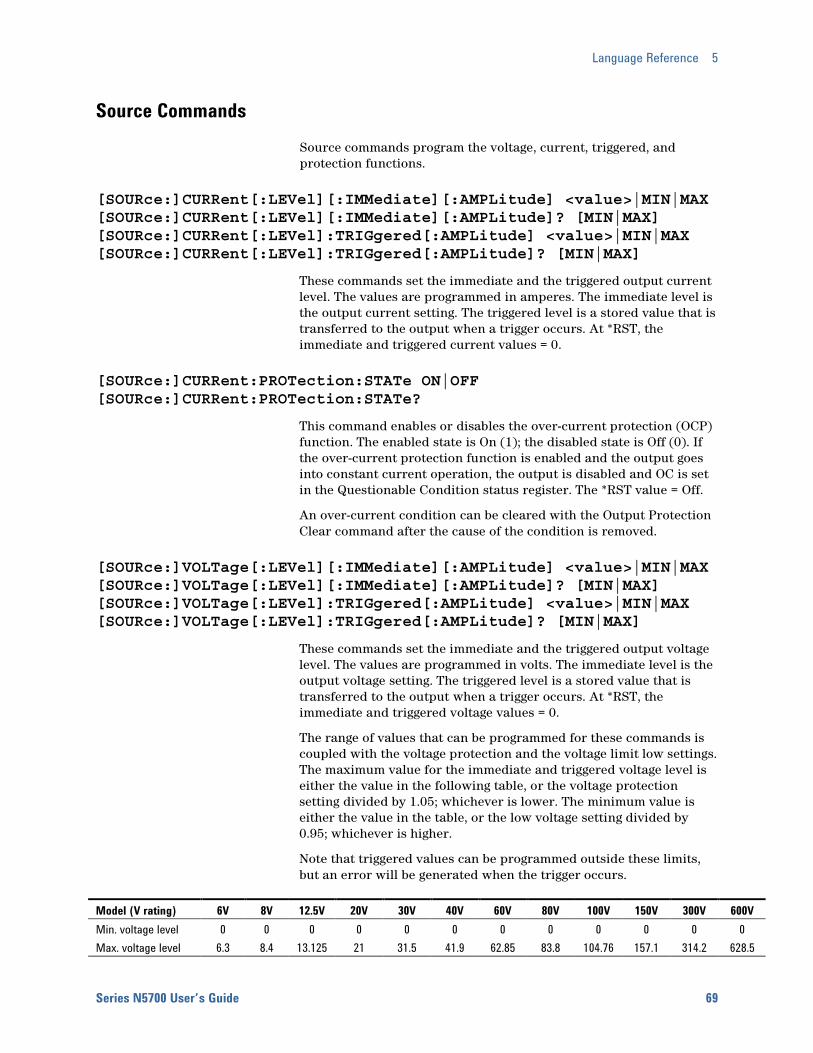
Language Reference 5
Series N5700 User’s Guide 69
Source Commands Source commands program the voltage, current, triggered, and protection functions.
[SOURce:]CURRent[:LEVel][:IMMediate][:AMPLitude] <value>|MIN|MAX [SOURce:]CURRent[:LEVel][:IMMediate][:AMPLitude]? [MIN|MAX] [SOURce:]CURRent[:LEVel]:TRIGgered[:AMPLitude] <value>|MIN|MAX [SOURce:]CURRent[:LEVel]:TRIGgered[:AMPLitude]? [MIN|MAX]
These commands set the immediate and the triggered output current level. The values are programmed in amperes. The immediate level is the output current setting. The triggered level is a stored value that is transferred to the output when a trigger occurs. At *RST, the immediate and triggered current values = 0.
[SOURce:]CURRent:PROTection:STATe ON|OFF [SOURce:]CURRent:PROTection:STATe?
This command enables or disables the over-current protection (OCP) function. The enabled state is On (1); the disabled state is Off (0). If the over-current protection function is enabled and the output goes into constant current operation, the output is disabled and OC is set in the Questionable Condition status register. The *RST value = Off.
An over-current condition can be cleared with the Output Protection Clear command after the cause of the condition is removed.
[SOURce:]VOLTage[:LEVel][:IMMediate][:AMPLitude] <value>|MIN|MAX [SOURce:]VOLTage[:LEVel][:IMMediate][:AMPLitude]? [MIN|MAX] [SOURce:]VOLTage[:LEVel]:TRIGgered[:AMPLitude] <value>|MIN|MAX [SOURce:]VOLTage[:LEVel]:TRIGgered[:AMPLitude]? [MIN|MAX]
These commands set the immediate and the triggered output voltage level. The values are programmed in volts. The immediate level is the output voltage setting. The triggered level is a stored value that is transferred to the output when a trigger occurs. At *RST, the immediate and triggered voltage values = 0.
The range of values that can be programmed for these commands is coupled with the voltage protection and the voltage limit low settings. The maximum value for the immediate and triggered voltage level is either the value in the following table, or the voltage protection setting divided by 1.05; whichever is lower. The minimum value is either the value in the table, or the low voltage setting divided by 0.95; whichever is higher.
Note that triggered values can be programmed outside these limits, but an error will be generated when the trigger occurs.
Model (V rating) 6V 8V 12.5V 20V 30V 40V 60V 80V 100V 150V 300V 600V Min. voltage level 0 0 0 0 0 0 0 0 0 0 0 0 Max. voltage level 6.3 8.4 13.125 21 31.5 41.9 62.85 83.8 104.76 157.1 314.2 628.5

5 Language Reference
70 Series N5700 User’s Guide
[SOURce:]VOLTage:LIMit:LOW <value>|MIN|MAX [SOURce:]VOLTage:LIMit:LOW? [MIN|MAX]
This command sets the low voltage limit of the output. When a low voltage limit has been set, the instrument will ignore any programming commands that attempt to set the output voltage below the low voltage limit. The*RST value = Max.
The range of values that can be programmed for this command is coupled with the immediate voltage level setting. The maximum value for the low voltage limit is either the value in the following table, or the immediate voltage setting multiplied by 0.95; whichever is lower. The minimum setting is the value in the table.
Model (V rating) 6V 8V 12.5V 20V 30V 40V 60V 80V 100V 150V 300V 600V Min. low limit 0 0 0 0 0 0 0 0 0 0 0 0 Max. low limit 5.7 7.6 11.9 19 28.5 38 57 76 95 142 285 570
[SOURce:]VOLTage:PROTection:LEVel <value>|MIN|MAX [SOURce:]VOLTage:PROTection:LEVel? [MIN|MAX]
This command sets the over-voltage protection (OVP) level of the output. The values are programmed in volts. If the output voltage exceeds the OVP level, the output is disabled and OV is set in the Questionable Condition status register. The*RST value = Max.
The range of values that can be programmed for this command is coupled with the immediate voltage level setting. The minimum value for the voltage protection level is either the value in the following table, or the immediate voltage setting multiplied by 1.05; whichever is higher. The maximum setting is the value in the table.
An over-voltage condition can be cleared with the Output Protection Clear command after the condition that caused the OVP trip is removed.
Model (V rating) 6V 8V 12.5V 20V 30V 40V 60V 80V 100V 150V 300V 600V Min. protection limit 0.5 0.5 1.0 1.0 2.0 2.0 5.0 5.0 5.0 5.0 5.0 5.0 Max. protection limit 7.5 10 15 24 36 44 66 88 110 165 330 660

Language Reference 5
Series N5700 User’s Guide 71
Status Commands Status commands program the power supply’s status registers. As shown in the following figure, the power supply has three groups of status registers; Operation, Questionable, and Standard Event. The Operation and Questionable status groups each consist of the Condition, Enable, and Event registers and NTR and PTR filters.
LOGICALOR
LOGICALOR
PON
CME
EXE
DDE
QYE
OPC 0
2
3
4
5
7
1
4
8
16
32
128
1
4
8
16
32
128
EVENT ENABLE
STANDARD EVENTSTATUS
STATUS BYTE
SERVICEREQUESTENABLE
LOGICALOR
SERVICEREQUEST
GENERATION
8
16
32
128
8
16
32
128
RQS
OPER
MSS
ESB
MAV
QUES
4
5
6
7
UNR
OT
OV 0
4
QUESTIONABLE STATUS
10
CONDITION
LOGICALOR
EVENT ENABLEPTR/NTR
1
16
1024
1
16
1024
1
16
1024
1
16
1024
3
CONDITION
5
8
PTR/NTR EVENT ENABLE
CV
CC
32
256
OC 1
WTG
OPERATION STATUS
PF 2 4 4
2
4 42 2 2
INH 9 512 512512512
64
10 1024
256
1024
256
1024
256
1024
OUTPUT BUFFER
QUEUENOT
EMPTY
Data
Data
Data
*STB? *SRE<n>*SRE?
*ESR?
STAT:QUES:COND?
*ESE<n>*ESE?
STAT:QUES:PTR |:NTR <n>STAT:QUES:PTR |:NTR ?
STAT:QUES:EVEN?
STAT:QUES:ENAB <n>STAT:QUES:ENAB
STAT:OPER:COND?
STAT:OPER:EVEN?
STAT:OPER:ENAB <n>STAT:OPER:ENABSTAT:OPER:PTR |:NTR <n>
STAT:OPER:PTR |:NTR ?
32 32 32
ERROR QUEUE
QUEUENOT
EMPTY
Err
Err
Err
442
ERROR

5 Language Reference
72 Series N5700 User’s Guide
The Standard Event group is programmed with Common commands as described later in this section. Common commands also control additional status functions such as the Service Request Enable and the Status Byte registers.
STATus:PRESet
This command sets all defined bits in the Operation and Questionable PTR registers. The command clears all defined bits in the Operation and Questionable NTR and Enable registers.
STATus:OPERation[:EVENt]?
This query returns the value of the Operation Event register. The Event register is a read-only register, which stores (latches) all events that are passed by the Operation NTR and/or PTR filter. Reading the Operation Event register clears it. The bit configuration of the Operation status registers is as follows:
Bit Position 15-11 10 9 8 7-6 5 4-0 Bit Value − 1024 − 256 − 32 − Bit Name − CC − CV − WTG −
CC = The output is in constant current CV = The output is in constant voltage WTG = The unit is waiting for a transient trigger
STATus:OPERation:CONDition?
This query returns the value of the Operation Condition register. That is a read-only register, which holds the live (unlatched) operational status of the power supply.
STATus:OPERation:ENABle <value> STATus:OPERation:ENABle?
This command and its query set and read the value of the Operational Enable register. This register is a mask for enabling specific bits from the Operation Event register to set the operation summary bit (OPER) of the Status Byte register. This bit (bit 7) is the logical OR of all the Operational Event register bits that are enabled by the Status Operation Enable register. The Preset value = 0.

Language Reference 5
Series N5700 User’s Guide 73
STATus:OPERation:NTR <value> STATus:OPERation:PTR <value> STATus:OPERation:NTR? STATus:OPERation:PTR?
These commands set or read the value of the Operation NTR (Negative-Transition) and PTR (Positive-Transition) registers. These registers serve as polarity filters between the Operation Condition and Operation Event registers to cause the following actions:
When a bit in the Operation NTR register is set to 1, then a 1-to-0 transition of the corresponding bit in the Operation Condition register causes that bit in the Operation Event register to be set.
When a bit of the Operation PTR register is set to 1, then a 0-to-1 transition of the corresponding bit in the Operation Condition register causes that bit in the Operation Event register to be set.
If the same bits in both NTR and PTR registers are set to 1, then any transition of that bit at the Operation Condition register sets the corresponding bit in the Operation Event register.
If the same bits in both NTR and PTR registers are set to 0, then no transition of that bit at the Operation Condition register can set the corresponding bit in the Operation Event register.
The Preset value are: NTR = 0; PTR = 32767
STATus:QUEStionable[:EVENt]?
This query returns the value of the Questionable Event register. The Event register is a read-only register, which stores (latches) all events that are passed by the Questionable NTR and/or PTR filter. Reading the Questionable Event register clears it. The bit configuration of the Questionable status registers is as follows:
Bit Position 15-11 10 9 8-5 4 3 2 1 0 Bit Value − 1024 512 − 16 − 4 2 1 Bit Name − UNR INH − OT − PF OC OV UNR = The output is unregulated INH = The output is turned off by one of the external J1 inhibit signals OT = The output is disabled by the over-temperature protection PF = The output is disabled because AC power has failed OC = The output is disabled by the over-current protection OV = The output is disabled by the over-voltage protection
STATus:QUEStionable:CONDition?
This query returns the value of the Questionable Condition register. That is a read-only register, which holds the real-time (unlatched) questionable status of the power supply.

5 Language Reference
74 Series N5700 User’s Guide
STATus:QUEStionable:ENABle <value> STATus:QUEStionable:ENABle?
This command and its query set and read the value of the Questionable Enable register. This register is a mask for enabling specific bits from the Questionable Event register to set the questionable summary bit (QUES) of the Status Byte register. This bit (bit 3) is the logical OR of all the Questionable Event register bits that are enabled by the Questionable Status Enable register. The Preset value = 0.
STATus:QUEStionable:NTR <value> STATus:QUEStionable:PTR <value> STATus:QUEStionable:NTR? STATus:QUEStionable:PTR?
These commands set or read the value of the Questionable NTR (Negative-Transition) and PTR (Positive-Transition) registers. These registers serve as polarity filters between the Questionable Condition and Questionable Event registers to cause the following actions:
When a bit of the Questionable NTR register is set to 1, then a 1-to-0 transition of the corresponding bit of the Questionable Condition register causes that bit in the Questionable Event register to be set.
When a bit of the Questionable PTR register is set to 1, then a 0-to-1 transition of the corresponding bit in the Questionable Condition register causes that bit in the Questionable Event register to be set.
If the same bits in both NTR and PTR registers are set to 1, then any transition of that bit at the Questionable Condition register sets the corresponding bit in the Questionable Event register.
If the same bits in both NTR and PTR registers are set to 0, then no transition of that bit at the Questionable Condition register can set the corresponding bit in the Questionable Event register.
The Preset values are: NTR = 0; PTR = 32767
*CLS
This command causes the following actions on the status system:
Clears the Standard Event Status, Operation Status Event, and Questionable Status Event registers
Clears the Status Byte and the Error Queue
If *CLS immediately follows a program message terminator (<NL>), then the output queue and the MAV bit are also cleared.
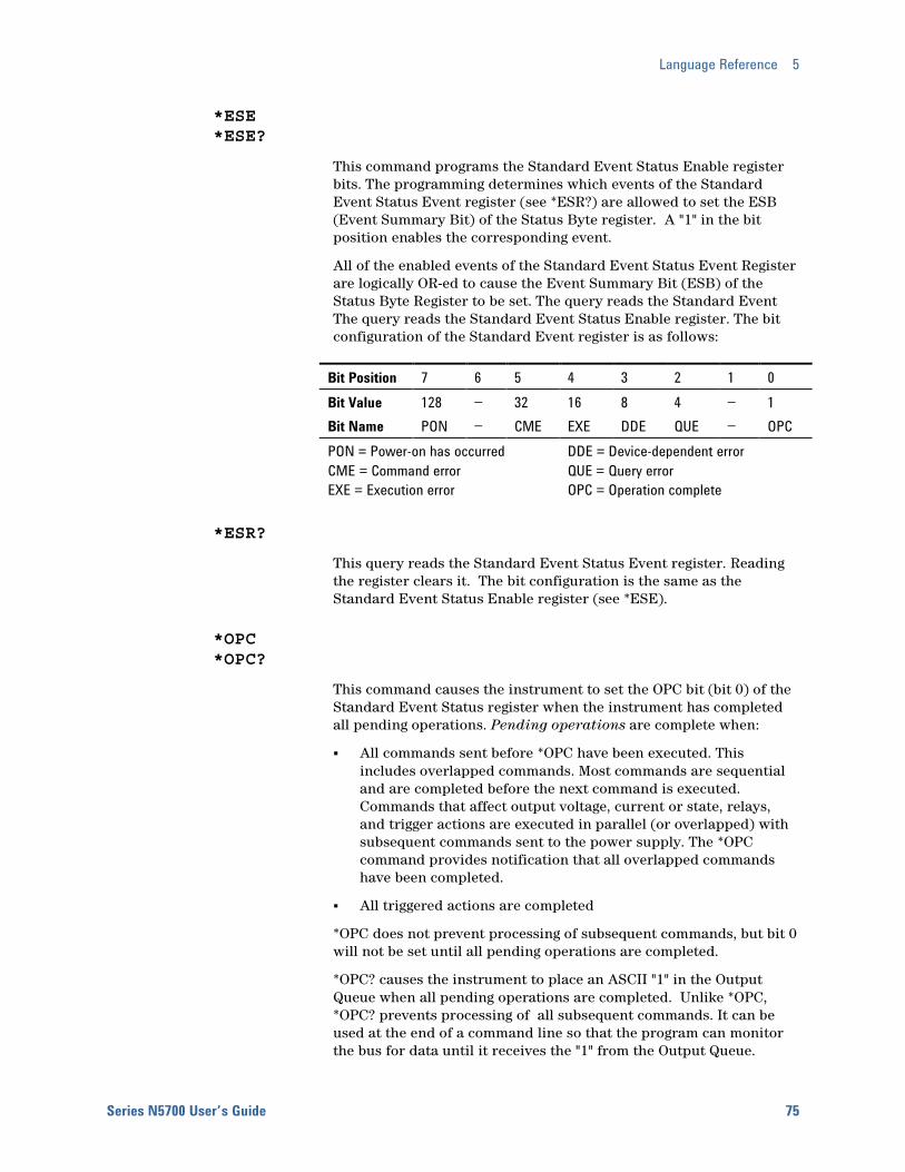
Language Reference 5
Series N5700 User’s Guide 75
*ESE *ESE?
This command programs the Standard Event Status Enable register bits. The programming determines which events of the Standard Event Status Event register (see *ESR?) are allowed to set the ESB (Event Summary Bit) of the Status Byte register. A "1" in the bit position enables the corresponding event.
All of the enabled events of the Standard Event Status Event Register are logically OR-ed to cause the Event Summary Bit (ESB) of the Status Byte Register to be set. The query reads the Standard Event The query reads the Standard Event Status Enable register. The bit configuration of the Standard Event register is as follows:
Bit Position 7 6 5 4 3 2 1 0 Bit Value 128 − 32 16 8 4 − 1 Bit Name PON − CME EXE DDE QUE − OPC PON = Power-on has occurred CME = Command error EXE = Execution error
DDE = Device-dependent error QUE = Query error OPC = Operation complete
*ESR?
This query reads the Standard Event Status Event register. Reading the register clears it. The bit configuration is the same as the Standard Event Status Enable register (see *ESE).
*OPC *OPC?
This command causes the instrument to set the OPC bit (bit 0) of the Standard Event Status register when the instrument has completed all pending operations. Pending operations are complete when:
All commands sent before *OPC have been executed. This includes overlapped commands. Most commands are sequential and are completed before the next command is executed. Commands that affect output voltage, current or state, relays, and trigger actions are executed in parallel (or overlapped) with subsequent commands sent to the power supply. The *OPC command provides notification that all overlapped commands have been completed.
All triggered actions are completed
*OPC does not prevent processing of subsequent commands, but bit 0 will not be set until all pending operations are completed.
*OPC? causes the instrument to place an ASCII "1" in the Output Queue when all pending operations are completed. Unlike *OPC, *OPC? prevents processing of all subsequent commands. It can be used at the end of a command line so that the program can monitor the bus for data until it receives the "1" from the Output Queue.

5 Language Reference
76 Series N5700 User’s Guide
*SRE *SRE?
This command sets the condition of the Service Request Enable Register. This register determines which bits from the Status Byte Register are allowed to set the Master Status Summary (MSS) bit and the Request for Service (RQS) summary bit. A 1 in any Service Request Enable Register bit position enables the corresponding Status Byte Register bit and all such enabled bits then are logically OR-ed to cause Bit 6 of the Status Byte Register to be set.
When the controller conducts a serial poll in response to SRQ, the RQS bit is cleared, but the MSS bit is not. When *SRE is cleared (by programming it with 0), the power supply cannot generate an SRQ to the controller. The query returns the current state of *SRE.
*STB?
This query reads the Status Byte register, which contains the status summary bits and the Output Queue MAV bit. Reading the Status Byte register does not clear it. The input summary bits are cleared when the appropriate event registers are read. The MAV bit is cleared at power-on, by *CLS' or when there is no more response data available.
A serial poll also returns the value of the Status Byte register, except that bit 6 returns Request for Service (RQS) instead of Master Status Summary (MSS). A serial poll clears RQS, but not MSS. When MSS is set, it indicates that the power supply has one or more reasons for requesting service.
Bit Position 7 6 5 4 3 2 1 − 0 Bit Value 128 64 32 16 8 4 − Bit Name OPER MSS
(RQS) ESB MAV QUES ERR −
OPER = Operation status summary MSS = Master status summary (RQS) = Request for service ESB = Event status byte summary
MAV = Message available QUES = Questionable status summaryERR = Error queue not empty
*WAI
This command instructs the power supply not to process any further commands until all pending operations are completed. Pending operations are as defined under the *OPC command. *WAI can be aborted only by sending the power supply a Device Clear command.
Language Reference 5
Series N5700 User’s Guide 77
System Commands System commands control system functions that are not directly related to output control, measurement, or status functions. Common commands are also used to control system functions.
SYSTem:COMMunicate:RLSTate LOCal|REMote|RWLock SYSTem:COMMunicate:RLSTate?
This command configures the remote/local state of the instrument according to the following settings.
LOCal The instrument is set to front panel control (front panel keys are active).
REMote The instrument is set to remote interface control (front panel keys are active).
RWLock The front panel keys are disabled (the instrument can only be controlled via the remote interface).
The remote/local state can also be set by interface commands over the GPIB and some other I/O interfaces. When multiple remote programming interfaces are active, the interface with the most recently changed remote/local state determines the instrument’s remote/local state.
The remote/local state is unaffected by *RST or any SCPI commands other than SYSTem:COMMunicate:RLState. At power-on however, the communications setting always returns to LOCal.
SYSTem:COMMunicate:TCPip:CONTrol?
This query returns the control connection port number. This is used to open a control socket connection to the instrument. Refer to chapter 4 under “Using Sockets” for more information.
SYSTem:ERRor?
This query returns the next error number and its corresponding message string from the error queue. The queue is a FIFO (first-in, first-out) buffer that stores errors as they occur. As it is read, each error is removed from the queue. When all errors have been read, the query returns 0, NO ERROR. If more errors are accumulated than the queue can hold, the last error in the queue will be -350, TOO MANY ERRORS (see Appendix C for error codes).
SYSTem:VERSion?
This query returns the SCPI version number to which the instrument complies. The returned value is of the form YYYY.V, where YYYY represents the year and V is the revision number for that year.
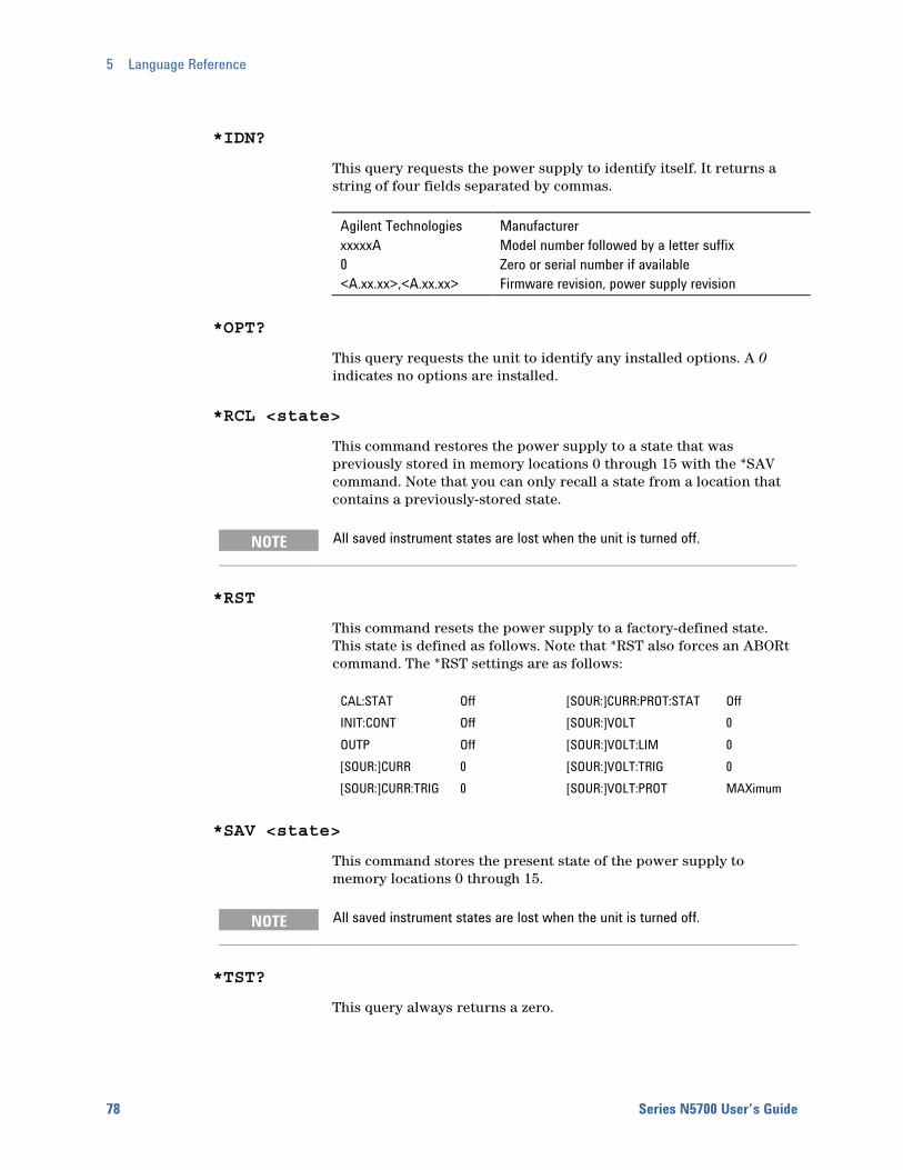
5 Language Reference
78 Series N5700 User’s Guide
*IDN?
This query requests the power supply to identify itself. It returns a string of four fields separated by commas.
Agilent Technologies xxxxxA 0 <A.xx.xx>,<A.xx.xx>
Manufacturer Model number followed by a letter suffix Zero or serial number if available Firmware revision, power supply revision
*OPT?
This query requests the unit to identify any installed options. A 0 indicates no options are installed.
*RCL <state>
This command restores the power supply to a state that was previously stored in memory locations 0 through 15 with the *SAV command. Note that you can only recall a state from a location that contains a previously-stored state.
NOTE All saved instrument states are lost when the unit is turned off.
*RST
This command resets the power supply to a factory-defined state. This state is defined as follows. Note that *RST also forces an ABORt command. The *RST settings are as follows:
CAL:STAT Off [SOUR:]CURR:PROT:STAT Off INIT:CONT Off [SOUR:]VOLT 0 OUTP Off [SOUR:]VOLT:LIM 0 [SOUR:]CURR 0 [SOUR:]VOLT:TRIG 0 [SOUR:]CURR:TRIG 0 [SOUR:]VOLT:PROT MAXimum
*SAV <state>
This command stores the present state of the power supply to memory locations 0 through 15.
NOTE All saved instrument states are lost when the unit is turned off.
*TST?
This query always returns a zero.
Language Reference 5
Series N5700 User’s Guide 79
Trigger Commands Trigger commands consist of the Abort, Trigger, and Initiate commands. Initiate commands initialize the trigger system. Trigger commands control the triggering of the power supply.
ABORt
This command cancels any trigger actions in progress and returns the trigger system to the IDLE state, unless INIT:CONT is enabled. It also resets the WTG bit in the Status Operation Condition register. ABORt is executed at power-on and upon execution of *RST.
INITiate[:IMMediate][:TRANsient]
This command controls the enabling of output triggers. When a trigger is enabled, a trigger causes the specified triggering action to occur. If the trigger system is not enabled, all triggers are ignored.
INITiate:CONTinuous[:TRANsient] ON|OFF INITiate:CONTinuous[:TRANsient]?
This command continuously initiates output triggers. The enabled state is On (1); the disabled state is Off (0). When disabled, the trigger system must be initiated for each trigger with the INITiate command.
TRIGger[:TRANsient][:IMMediate]
If the trigger system has been initiated, this command generates an immediate output trigger. When sent, the output trigger will:
Initiate an output change as specified by the CURR:TRIG or VOLT:TRIG settings.
Clear the WTG bits in the Status Operation Condition register after the trigger action has completed.
TRIGger:SOURce BUS TRIGger:SOURce?
This command selects the trigger source for the output trigger system. Only BUS can be selected as the trigger source.
*TRG
This command generates a trigger when the trigger source is set to BUS. The command has the same affect as the Group Execute Trigger (<GET>) command.


Series N5700 User’s Guide 81
6 Programming Examples Output Programming Example ........................................................................ 82 Trigger Programming Example........................................................................ 84
This chapter contains several example programs to help you develop programs for your own application. The example programs are for illustration only, and are provided with the assumption that you are familiar with the programming language being demonstrated and the tools used to create and debug procedures. See Chapter 5, “Language Dictionary” for the SCPI command syntax.
You have a royalty-free right to use, modify, reproduce and distribute the example programs (and/or any modified version) in any way you find useful, provided you agree that Agilent Technologies has no warranty, obligations, or liability for any example programs.
The example programs are written in Microsoft Visual Basic 6.0 using the VISA COM IO library. The VISA COM library must be downloaded from the Automation-Ready CD-ROM to use these programs. For information about using VISA COM in another Visual Basic project, refer to “Programming Your Instruments” in the USB/LAN/GPIB Interfaces Connectivity Guide, also included on the Automation-Ready CD-ROM.
NOTE Example programs for the following programming environments are also included on the Product-Reference CD-ROM located at the back of this guide: Microsoft Visual Basic 6.0 Microsoft Visual C++ 6.0 Microsoft Excel The CD also contains IVI-COM and LabVIEW drivers for your power supply.

6 Programming Examples
82 Series N5700 User’s Guide
Output Programming Example
This program sets the voltage, current, over-voltage, and the over-current protection. It turns the output on and takes a voltage measurement. When done, the program checks for instrument errors and gives a message if there is an error.
Sub main_EZ() Dim IDN As String Dim IOaddress As String Dim ErrString As String ' This variable controls the voltage Dim VoltSetting As Double ' This variable measures the voltage Dim measVolt As Double ' This variable controls the current Dim CurrSetting As Double ' These variables control the over voltage protection settings Dim overVoltSetting As Double ' These variables control the over current protection Dim overCurrOn As Long 'These variable are neccessary to initialize the VISA COM. Dim ioMgr As AgilentRMLib.SRMCls Dim Instrument As VisaComLib.FormattedIO488 ' The following command line provides the program with the VISA name of the ' interface that it will communicate with. It is currently set to use GPIB. IOaddress = "GPIB0::5::INSTR" ' Use the following line for LAN communication ' IOaddress="TCPIP0::141.25.36.214" ' Use the following line instead for USB communication ' IOaddress = "USB0::2391::1799::US00000002" ' Initialize the VISA COM communication Set ioMgr = New AgilentRMLib.SRMCls Set Instrument = New VisaComLib.FormattedIO488 Set Instrument.IO = ioMgr.Open(IOaddress) VoltSetting = 3 CurrSetting = 1.5 ' amps overVoltSetting = 10 overCurrOn = 1 '1 for on, 0 for off With Instrument ' Send a power reset to the instrument .WriteString "*RST" ' Query the instrument for the IDN string .WriteString "*IDN?" IDN = .ReadString ' Set the voltage .WriteString "VOLT" & Str$(VoltSetting)
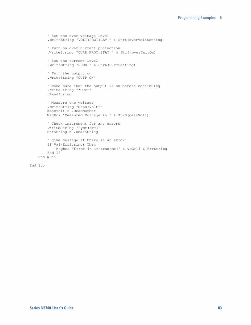
Programming Examples 6
Series N5700 User’s Guide 83
' Set the over voltage level .WriteString "VOLT:PROT:LEV " & Str$(overVoltSetting) ' Turn on over current protection .WriteString "CURR:PROT:STAT " & Str$(overCurrOn) ' Set the current level .WriteString "CURR " & Str$(CurrSetting) ' Turn the output on .WriteString "OUTP ON" ' Make sure that the output is on before continuing .WriteString "*OPC?" .ReadString ' Measure the voltage .WriteString "Meas:Volt?" measVolt = .ReadNumber MsgBox "Measured Voltage is " & Str$(measVolt) ' Check instrument for any errors .WriteString "Syst:err?" ErrString = .ReadString ' give message if there is an error If Val(ErrString) Then MsgBox "Error in instrument!" & vbCrLf & ErrString End If End With End Sub
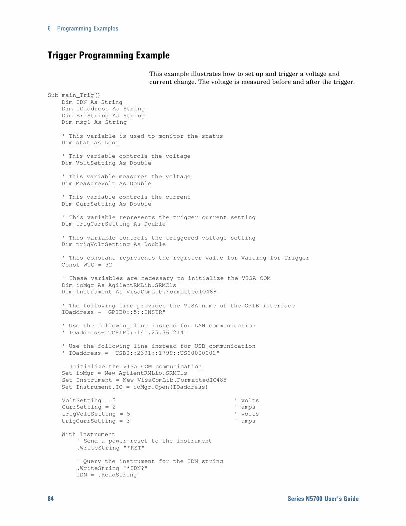
6 Programming Examples
84 Series N5700 User’s Guide
Trigger Programming Example
This example illustrates how to set up and trigger a voltage and current change. The voltage is measured before and after the trigger.
Sub main_Trig() Dim IDN As String Dim IOaddress As String Dim ErrString As String Dim msg1 As String ' This variable is used to monitor the status Dim stat As Long ' This variable controls the voltage Dim VoltSetting As Double ' This variable measures the voltage Dim MeasureVolt As Double ' This variable controls the current Dim CurrSetting As Double ' This variable represents the trigger current setting Dim trigCurrSetting As Double ' This variable controls the triggered voltage setting Dim trigVoltSetting As Double ' This constant represents the register value for Waiting for Trigger Const WTG = 32 ' These variables are necessary to initialize the VISA COM Dim ioMgr As AgilentRMLib.SRMCls Dim Instrument As VisaComLib.FormattedIO488 ' The following line provides the VISA name of the GPIB interface IOaddress = "GPIB0::5::INSTR" ' Use the following line instead for LAN communication ' IOaddress="TCPIP0::141.25.36.214" ' Use the following line instead for USB communication ' IOaddress = "USB0::2391::1799::US00000002" ' Initialize the VISA COM communication Set ioMgr = New AgilentRMLib.SRMCls Set Instrument = New VisaComLib.FormattedIO488 Set Instrument.IO = ioMgr.Open(IOaddress) VoltSetting = 3 ' volts CurrSetting = 2 ' amps trigVoltSetting = 5 ' volts trigCurrSetting = 3 ' amps With Instrument ' Send a power reset to the instrument .WriteString "*RST" ' Query the instrument for the IDN string .WriteString "*IDN?" IDN = .ReadString
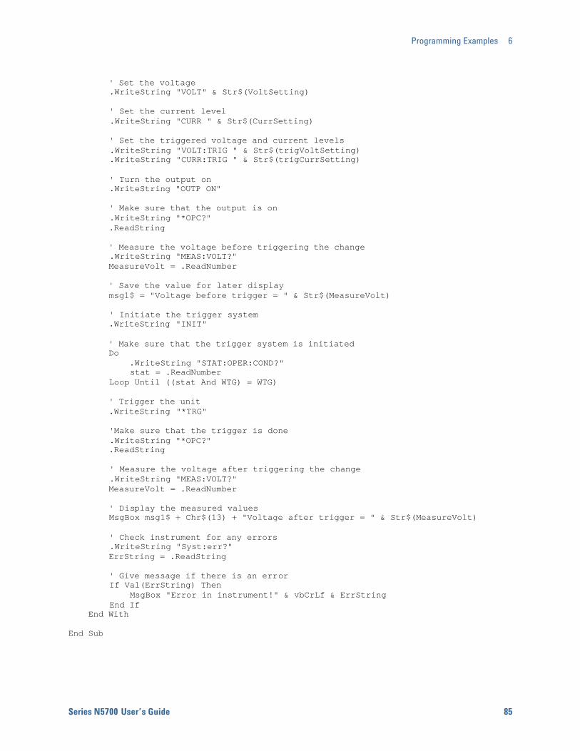
Programming Examples 6
Series N5700 User’s Guide 85
' Set the voltage .WriteString "VOLT" & Str$(VoltSetting) ' Set the current level .WriteString "CURR " & Str$(CurrSetting) ' Set the triggered voltage and current levels .WriteString "VOLT:TRIG " & Str$(trigVoltSetting) .WriteString "CURR:TRIG " & Str$(trigCurrSetting) ' Turn the output on .WriteString "OUTP ON" ' Make sure that the output is on .WriteString "*OPC?" .ReadString ' Measure the voltage before triggering the change .WriteString "MEAS:VOLT?" MeasureVolt = .ReadNumber ' Save the value for later display msg1$ = "Voltage before trigger = " & Str$(MeasureVolt) ' Initiate the trigger system .WriteString "INIT" ' Make sure that the trigger system is initiated Do .WriteString "STAT:OPER:COND?" stat = .ReadNumber Loop Until ((stat And WTG) = WTG) ' Trigger the unit .WriteString "*TRG" 'Make sure that the trigger is done .WriteString "*OPC?" .ReadString ' Measure the voltage after triggering the change .WriteString "MEAS:VOLT?" MeasureVolt = .ReadNumber ' Display the measured values MsgBox msg1$ + Chr$(13) + "Voltage after trigger = " & Str$(MeasureVolt) ' Check instrument for any errors .WriteString "Syst:err?" ErrString = .ReadString ' Give message if there is an error If Val(ErrString) Then MsgBox "Error in instrument!" & vbCrLf & ErrString End If End With End Sub


Series N5700 User’s Guide 87
Appendix A Specifications Performance Specifications ............................................................................ 88 Supplemental Characteristics ......................................................................... 89 Outline Diagram................................................................................................. 91
This chapter lists the specifications and supplemental characteristics of the Agilent N5700 power supplies. A dimensional line drawing of the unit is included at the end of the chapter.
Unless otherwise noted, specifications are warranted over the ambient temperature range of 0 to 40°C. Sensing is at the rear terminals of the power supply after a 30-minute warm-up period. Sense terminals are externally jumpered to their respective output terminals.
Supplemental characteristics are not warranted but are descriptions of typical performance determined either by design or type testing.
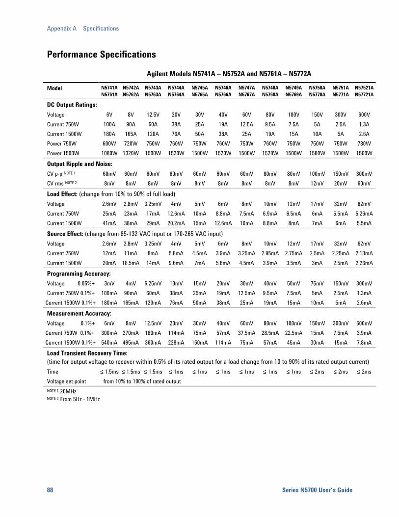
Appendix A Specifications
88 Series N5700 User’s Guide
Performance Specifications
Agilent Models N5741A – N5752A and N5761A – N5772A
Model N5741A N5761A
N5742A N5762A
N5743AN5763A
N5744AN5764A
N5745AN5765A
N5746AN5766A
N5747AN5767A
N5748AN5768A
N5749A N5769A
N5750AN5770A
N5751AN5771A
N57521AN57721A
DC Output Ratings: Voltage 6V 8V 12.5V 20V 30V 40V 60V 80V 100V 150V 300V 600V Current 750W 100A 90A 60A 38A 25A 19A 12.5A 9.5A 7.5A 5A 2.5A 1.3A Current 1500W 180A 165A 120A 76A 50A 38A 25A 19A 15A 10A 5A 2.6A Power 750W 600W 720W 750W 760W 750W 760W 750W 760W 750W 750W 750W 780W Power 1500W 1080W 1320W 1500W 1520W 1500W 1520W 1500W 1520W 1500W 1500W 1500W 1560W
Output Ripple and Noise: CV p-p NOTE 1 60mV 60mV 60mV 60mV 60mV 60mV 60mV 80mV 80mV 100mV 150mV 300mV CV rms NOTE 2 8mV 8mV 8mV 8mV 8mV 8mV 8mV 8mV 8mV 12mV 20mV 60mV
Load Effect: (change from 10% to 90% of full load) Voltage 2.6mV 2.8mV 3.25mV 4mV 5mV 6mV 8mV 10mV 12mV 17mV 32mV 62mV Current 750W 25mA 23mA 17mA 12.6mA 10mA 8.8mA 7.5mA 6.9mA 6.5mA 6mA 5.5mA 5.26mACurrent 1500W 41mA 38mA 29mA 20.2mA 15mA 12.6mA 10mA 8.8mA 8mA 7mA 6mA 5.5mA
Source Effect: (change from 85-132 VAC input or 170-265 VAC input) Voltage 2.6mV 2.8mV 3.25mV 4mV 5mV 6mV 8mV 10mV 12mV 17mV 32mV 62mV Current 750W 12mA 11mA 8mA 5.8mA 4.5mA 3.9mA 3.25mA 2.95mA 2.75mA 2.5mA 2.25mA 2.13mACurrent 1500W 20mA 18.5mA 14mA 9.6mA 7mA 5.8mA 4.5mA 3.9mA 3.5mA 3mA 2.5mA 2.26mA
Programming Accuracy: Voltage 0.05%+ 3mV 4mV 6.25mV 10mV 15mV 20mV 30mV 40mV 50mV 75mV 150mV 300mV Current 750W 0.1%+ 100mA 90mA 60mA 38mA 25mA 19mA 12.5mA 9.5mA 7.5mA 5mA 2.5mA 1.3mA
Current 1500W 0.1%+ 180mA 165mA 120mA 76mA 50mA 38mA 25mA 19mA 15mA 10mA 5mA 2.6mA
Measurement Accuracy: Voltage 0.1%+ 6mV 8mV 12.5mV 20mV 30mV 40mV 60mV 80mV 100mV 150mV 300mV 600mV
Current 750W 0.1%+ 300mA 270mA 180mA 114mA 75mA 57mA 37.5mA 28.5mA 22.5mA 15mA 7.5mA 3.9mA Current 1500W 0.1%+ 540mA 495mA 360mA 228mA 150mA 114mA 75mA 57mA 45mA 30mA 15mA 7.8mA
Load Transient Recovery Time: (time for output voltage to recover within 0.5% of its rated output for a load change from 10 to 90% of its rated output current) Time ≤ 1.5ms ≤ 1.5ms ≤ 1.5ms ≤ 1ms ≤ 1ms ≤ 1ms ≤ 1ms ≤ 1ms ≤ 1ms ≤ 2ms ≤ 2ms ≤ 2ms Voltage set point from 10% to 100% of rated output NOTE 1 20MHz NOTE 2 From 5Hz - 1MHz
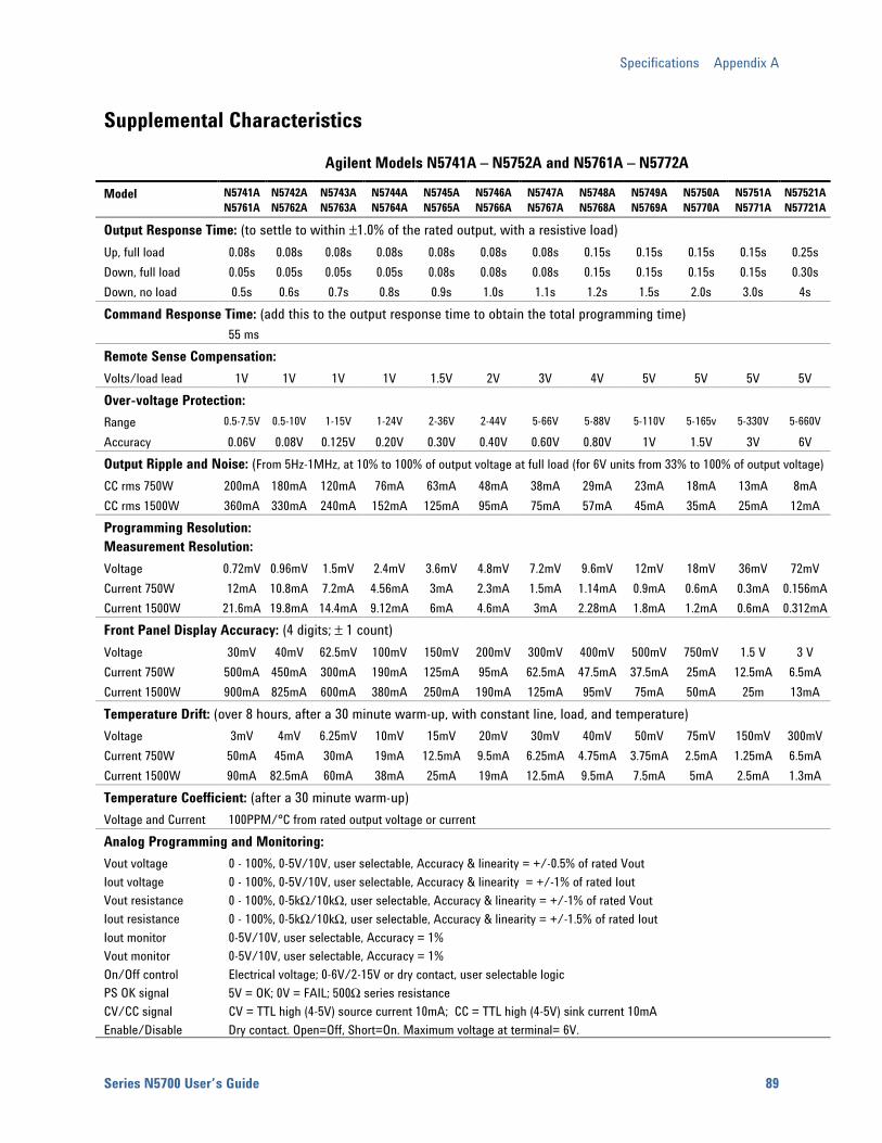
Specifications Appendix A
Series N5700 User’s Guide 89
Supplemental Characteristics
Agilent Models N5741A – N5752A and N5761A – N5772A
Model N5741A N5761A
N5742A N5762A
N5743AN5763A
N5744AN5764A
N5745AN5765A
N5746AN5766A
N5747AN5767A
N5748AN5768A
N5749A N5769A
N5750AN5770A
N5751AN5771A
N57521AN57721A
Output Response Time: (to settle to within ±1.0% of the rated output, with a resistive load) Up, full load 0.08s 0.08s 0.08s 0.08s 0.08s 0.08s 0.08s 0.15s 0.15s 0.15s 0.15s 0.25s Down, full load 0.05s 0.05s 0.05s 0.05s 0.08s 0.08s 0.08s 0.15s 0.15s 0.15s 0.15s 0.30s Down, no load 0.5s 0.6s 0.7s 0.8s 0.9s 1.0s 1.1s 1.2s 1.5s 2.0s 3.0s 4s Command Response Time: (add this to the output response time to obtain the total programming time) 55 ms Remote Sense Compensation: Volts/load lead 1V 1V 1V 1V 1.5V 2V 3V 4V 5V 5V 5V 5V Over-voltage Protection: Range 0.5-7.5V 0.5-10V 1-15V 1-24V 2-36V 2-44V 5-66V 5-88V 5-110V 5-165v 5-330V 5-660V
Accuracy 0.06V 0.08V 0.125V 0.20V 0.30V 0.40V 0.60V 0.80V 1V 1.5V 3V 6V Output Ripple and Noise: (From 5Hz-1MHz, at 10% to 100% of output voltage at full load (for 6V units from 33% to 100% of output voltage)CC rms 750W 200mA 180mA 120mA 76mA 63mA 48mA 38mA 29mA 23mA 18mA 13mA 8mA CC rms 1500W 360mA 330mA 240mA 152mA 125mA 95mA 75mA 57mA 45mA 35mA 25mA 12mA Programming Resolution: Measurement Resolution: Voltage 0.72mV 0.96mV 1.5mV 2.4mV 3.6mV 4.8mV 7.2mV 9.6mV 12mV 18mV 36mV 72mV Current 750W 12mA 10.8mA 7.2mA 4.56mA 3mA 2.3mA 1.5mA 1.14mA 0.9mA 0.6mA 0.3mA 0.156mACurrent 1500W 21.6mA 19.8mA 14.4mA 9.12mA 6mA 4.6mA 3mA 2.28mA 1.8mA 1.2mA 0.6mA 0.312mAFront Panel Display Accuracy: (4 digits; ± 1 count) Voltage 30mV 40mV 62.5mV 100mV 150mV 200mV 300mV 400mV 500mV 750mV 1.5 V 3 V Current 750W 500mA 450mA 300mA 190mA 125mA 95mA 62.5mA 47.5mA 37.5mA 25mA 12.5mA 6.5mA Current 1500W 900mA 825mA 600mA 380mA 250mA 190mA 125mA 95mV 75mA 50mA 25m 13mA Temperature Drift: (over 8 hours, after a 30 minute warm-up, with constant line, load, and temperature) Voltage 3mV 4mV 6.25mV 10mV 15mV 20mV 30mV 40mV 50mV 75mV 150mV 300mV Current 750W 50mA 45mA 30mA 19mA 12.5mA 9.5mA 6.25mA 4.75mA 3.75mA 2.5mA 1.25mA 6.5mA Current 1500W 90mA 82.5mA 60mA 38mA 25mA 19mA 12.5mA 9.5mA 7.5mA 5mA 2.5mA 1.3mA Temperature Coefficient: (after a 30 minute warm-up) Voltage and Current 100PPM/°C from rated output voltage or current Analog Programming and Monitoring: Vout voltage 0 - 100%, 0-5V/10V, user selectable, Accuracy & linearity = +/-0.5% of rated Vout Iout voltage 0 - 100%, 0-5V/10V, user selectable, Accuracy & linearity = +/-1% of rated Iout Vout resistance 0 - 100%, 0-5kΩ/10kΩ, user selectable, Accuracy & linearity = +/-1% of rated Vout Iout resistance 0 - 100%, 0-5kΩ/10kΩ, user selectable, Accuracy & linearity = +/-1.5% of rated Iout Iout monitor 0-5V/10V, user selectable, Accuracy = 1% Vout monitor 0-5V/10V, user selectable, Accuracy = 1% On/Off control Electrical voltage; 0-6V/2-15V or dry contact, user selectable logic PS OK signal 5V = OK; 0V = FAIL; 500Ω series resistance CV/CC signal CV = TTL high (4-5V) source current 10mA; CC = TTL high (4-5V) sink current 10mA Enable/Disable Dry contact. Open=Off, Short=On. Maximum voltage at terminal= 6V.
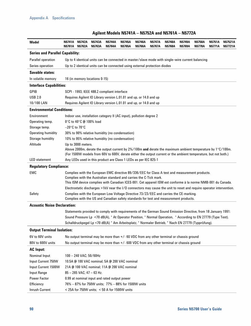
Appendix A Specifications
90 Series N5700 User’s Guide
Agilent Models N5741A – N5752A and N5761A – N5772A
Model N5741A N5761A
N5742A N5762A
N5743AN5763A
N5744AN5764A
N5745AN5765A
N5746AN5766A
N5747AN5767A
N5748AN5768A
N5749A N5769A
N5750AN5770A
N5751AN5771A
N57521AN57721A
Series and Parallel Capability: Parallel operation Up to 4 identical units can be connected in master/slave mode with single–wire current balancing Series operation Up to 2 identical units can be connected using external protection diodes
Savable states: In volatile memory 16 (in memory locations 0-15)
Interface Capabilities: GPIB USB 2.0 10/100 LAN
SCPI - 1993, IEEE 488.2 compliant interface Requires Agilent IO Library version L.01.01 and up, or 14.0 and up Requires Agilent IO Library version L.01.01 and up, or 14.0 and up
Environmental Conditions: Environment Operating temp. Storage temp. Operating humidity Storage humidity Altitude LED statement
Indoor use, installation category II (AC input), pollution degree 2 0°C to 40°C @ 100% load –20°C to 70°C 30% to 90% relative humidity (no condensation) 10% to 95% relative humidity (no condensation) Up to 3000 meters. Above 2000m, derate the output current by 2%/100m and derate the maximum ambient temperature by 1°C/100m. (For 1500W models from 60V to 600V, derate either the output current or the ambient temperature, but not both.) Any LEDs used in this product are Class 1 LEDs as per IEC 825-1
Regulatory Compliance: EMC Safety
Complies with the European EMC directive 89/336/EEC for Class A test and measurement products. Complies with the Australian standard and carries the C-Tick mark. This ISM device complies with Canadian ICES-001. Cet appareil ISM est conforme à la norme NMB-001 du Canada. Electrostatic discharges >1kV near the I/O connectors may cause the unit to reset and require operator intervention. Complies with the European Low Voltage Directive 73/23/EEC and carries the CE-marking. Complies with the US and Canadian safety standards for test and measurement products.
Acoustic Noise Declaration: Statements provided to comply with requirements of the German Sound Emission Directive, from 18 January 1991:
Sound Pressure Lp <70 dB(A), * At Operator Position, * Normal Operation, * According to EN 27779 (Type Test). Schalldruckpegel Lp <70 dB(A) * Am Arbeitsplatz, * Normaler Betrieb, * Nach EN 27779 (Typprüfung).
Output Terminal Isolation: 6V to 60V units No output terminal may be more than +/- 60 VDC from any other terminal or chassis ground 80V to 600V units No output terminal may be more than +/- 600 VDC from any other terminal or chassis ground
AC Input: Nominal Input Input Current 750W Input Current 1500W Input Range Power Factor Efficiency Inrush Current
100 – 240 VAC; 50/60Hz 10.5A @ 100 VAC nominal; 5A @ 200 VAC nominal 21A @ 100 VAC nominal; 11A @ 200 VAC nominal 85 – 265 VAC; 47 – 63 Hz. 0.99 at nominal input and rated output power 76% – 87% for 750W units; 77% – 88% for 1500W units < 25A for 750W units; < 50 A for 1500W units
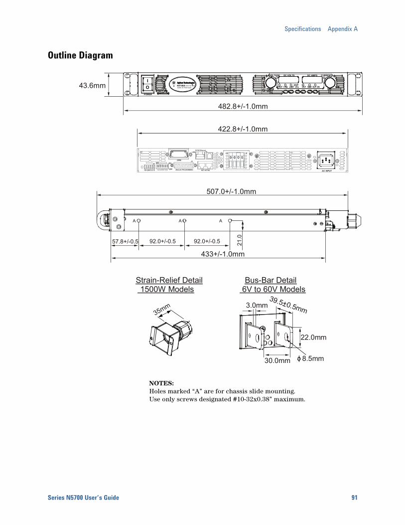
Specifications Appendix A
Series N5700 User’s Guide 91
Outline Diagram
NOTES: Holes marked “A” are for chassis slide mounting. Use only screws designated #10-32x0.38” maximum.
482.8+/-1.0mm
43.6mmVOLTAGE DC VOLTS DC AMPS CURRENT
PROT FINE LIMIT UVL OCP REM OUT ONOVP
POWER
IO
AAAAN5749A 100V/7.5A 750WSystem DC Power Supply
A A A
57.8+/-0.5 92.0+/-0.5 92.0+/-0.5 21.0
433+/-1.0mm
507.0+/-1.0mm
39.5+0.5mm
22.0mm
3.0mm
30.0mm
Bus-Bar Detail 6V to 60V Models
8.5mm
Strain-Relief Detail 1500W Models
35mm
AC INPUT
ON
OFF
422.8+/-1.0mm
+V -V
NOT ACTIVE
J2 SW1GPIB
ANALOG PROGRAMMING+S+LSNC-LC-S 1 2 3 4 5 6 7 8 9
10/100 EthernetLINK TX
J1

Series N5700 User’s Guide 93
Appendix B Verification and Calibration Verification ......................................................................................................... 94 Calibration ........................................................................................................113
The verification procedures described in this appendix verify that the power supply is operating normally and is within published specifications.
This appendix also includes calibration procedures for the Agilent N5700 power supplies. Instructions are given for performing the procedures from a controller over the GPIB.
NOTE Perform the verification tests before calibrating your power supply. If the power supply passes the verification tests, the unit is operating within its calibration limits and does not need to be re-calibrated.
The recommended calibration interval for Agilent N5700 power supplies is one year.
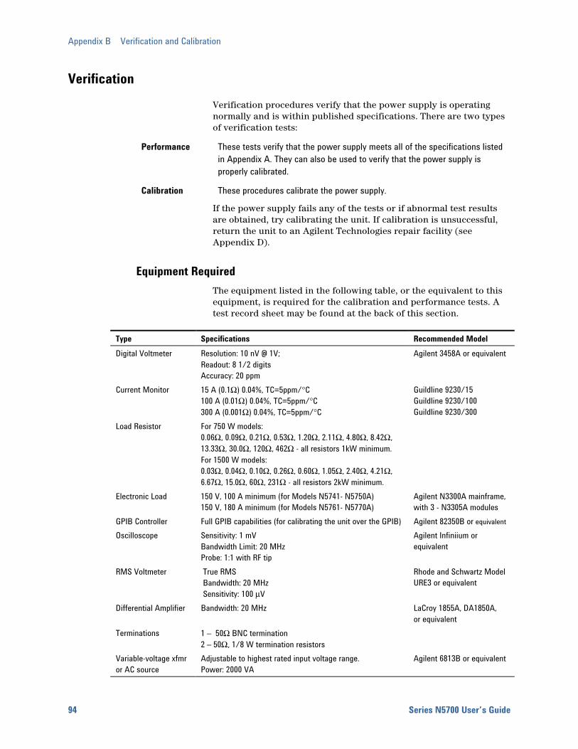
Appendix B Verification and Calibration
94 Series N5700 User’s Guide
Verification Verification procedures verify that the power supply is operating normally and is within published specifications. There are two types of verification tests:
Performance These tests verify that the power supply meets all of the specifications listed in Appendix A. They can also be used to verify that the power supply is properly calibrated.
Calibration These procedures calibrate the power supply.
If the power supply fails any of the tests or if abnormal test results are obtained, try calibrating the unit. If calibration is unsuccessful, return the unit to an Agilent Technologies repair facility (see Appendix D).
Equipment Required The equipment listed in the following table, or the equivalent to this equipment, is required for the calibration and performance tests. A test record sheet may be found at the back of this section.
Type Specifications Recommended Model Digital Voltmeter Resolution: 10 nV @ 1V;
Readout: 8 1/2 digits Accuracy: 20 ppm
Agilent 3458A or equivalent
Current Monitor 15 A (0.1Ω) 0.04%, TC=5ppm/°C 100 A (0.01Ω) 0.04%, TC=5ppm/°C 300 A (0.001Ω) 0.04%, TC=5ppm/°C
Guildline 9230/15 Guildline 9230/100 Guildline 9230/300
Load Resistor For 750 W models: 0.06Ω, 0.09Ω, 0.21Ω, 0.53Ω, 1.20Ω, 2.11Ω, 4.80Ω, 8.42Ω, 13.33Ω, 30.0Ω, 120Ω, 462Ω - all resistors 1kW minimum. For 1500 W models: 0.03Ω, 0.04Ω, 0.10Ω, 0.26Ω, 0.60Ω, 1.05Ω, 2.40Ω, 4.21Ω, 6.67Ω, 15.0Ω, 60Ω, 231Ω - all resistors 2kW minimum.
Electronic Load 150 V, 100 A minimum (for Models N5741- N5750A) 150 V, 180 A minimum (for Models N5761- N5770A)
Agilent N3300A mainframe, with 3 - N3305A modules
GPIB Controller Full GPIB capabilities (for calibrating the unit over the GPIB) Agilent 82350B or equivalent Oscilloscope Sensitivity: 1 mV
Bandwidth Limit: 20 MHz Probe: 1:1 with RF tip
Agilent Infiniium or equivalent
RMS Voltmeter True RMS Bandwidth: 20 MHz Sensitivity: 100 µV
Rhode and Schwartz Model URE3 or equivalent
Differential Amplifier Bandwidth: 20 MHz LaCroy 1855A, DA1850A, or equivalent
Terminations 1 – 50Ω BNC termination 2 – 50Ω, 1/8 W termination resistors
Variable-voltage xfmr or AC source
Adjustable to highest rated input voltage range. Power: 2000 VA
Agilent 6813B or equivalent

Verification and Calibration Appendix B
Series N5700 User’s Guide 95
Measurement Techniques
Electronic Load Many of the test procedures require the use of a variable load capable of dissipating the required power. If a variable resistor is used, switches should be used to either; connect, disconnect, or short the load resistor. For most tests, an electronic load can be used. The electronic load is considerably easier to use than load resistors, but it may not be fast enough to test transient recovery time and may be too noisy for the noise (PARD) tests.
Fixed load resistors may be used in place of a variable load, with minor changes to the test procedures. Also, if computer controlled test setups are used, the relatively slow (compared to computers and system voltmeters) settling times and slew rates of the power supply may have to be taken into account. "Wait" statements can be used in the test program if the test system is faster than the power supply.
Current-Monitoring Resistor The 4-terminal current shunt is used to eliminate output current measurement error caused by voltage drops in the load leads and connections. It has special current-monitoring terminals inside the load connection terminals. Connect the voltmeter directly to these current-monitoring terminals.
Test Set-up The following figure illustrates the test set-up used for the verification procedures.
A. Electronic loador resistor
DC voltmeter,scope, or
rms voltmeter
LoadResistor+
++
B.
Differentialamplifier
C.Scope or
rms voltmeter
Currentshunt
+DC voltmeter,
scope, orrms voltmeter
+Electronic load
or resistor
50 50
output
50 ohmtermination
input
BNC
BNC BNC
+V -VPower Supply
+S +LS -LS -S +V -VPower Supply
+S +LS -LS -S +V -VPower Supply
+S +LS -LS -S
Appendix B Verification and Calibration
96 Series N5700 User’s Guide
Constant Voltage Tests
NOTE Refer to the appropriate test record form for the instrument settings of the model you are checking.
Voltage Programming and Readback Accuracy Test category = performance, calibration
This test verifies that the voltage programming and measurement functions are within specifications.
1 Turn off the power supply and connect a DVM directly across the +S and -S terminals as shown in figure A. Do not connect a load.
2 Turn on the power supply and program the output voltage to zero and the output current to its maximum programmable value (Imax) with the load off. The CV annunciator should be on and the output current reading should be approximately zero.
3 Record the output voltage readings on the digital voltmeter (DVM) and the front panel display. The readings should be within the limits specified in the test record card for the appropriate model under Voltage Programming and Readback @ 0 V.
4 Program the output voltage to its full-scale rating.
5 Record the output voltage readings on the DVM and the front panel display. The readings should be within the limits specified in the test record card for the appropriate model under Voltage Programming and Readback @ Full Scale.
CV Load Effect Test category = performance
This test measures the change in output voltage resulting from a change in output current from full load to no load.
1 Turn off the power supply and connect a DVM and an electronic load as shown in figure A.
2 Turn on the power supply and program the output current to its maximum programmable value (Imax) and the output voltage to its full-scale value.
3 Set the electronic load for the output’s full-scale current. The CV annunciator on the front panel must be on. If it is not, adjust the load so that the output current drops slightly.
4 Record the output voltage reading from the DVM.
5 Open the load and record the voltage reading from the DVM again. The difference between the DVM readings in steps 4 and 5 is the load effect, which should not exceed the value listed in the test record card for the appropriate model under CV Load Effect.
Verification and Calibration Appendix B
Series N5700 User’s Guide 97
CV Source Effect Test category = performance
This test measures the change in output voltage that results from a change in AC line voltage from the minimum to maximum value within the line voltage specifications.
1 Turn off the power supply and connect the ac power line through a variable voltage transformer.
2 Connect a DVM and an electronic load as shown in figure A. Set the variable voltage transformer to nominal line voltage.
3 Turn on the power supply and program the output current to its maximum programmable value (Imax) and the output voltage to its full-scale value.
4 Set the electronic load for the output’s full-scale current. The CV annunciator on the front panel must be on. If it is not, adjust the load so that the output current drops slightly.
5 Adjust the transformer to the low-line voltage (85 VAC for 100/120 nominal line; 170 VAC for 200/240 nominal line).
6 Record the output voltage reading from the DVM.
7 Adjust the transformer to the high-line voltage (132 VAC for 100/120 nominal line; 265 VAC for 200/240 nominal line).
8 Record the output voltage reading on the DVM. The difference between the DVM reading in steps 6 and 8 is the source effect, which should not exceed the value listed in the test record card for the appropriate model under CV Source Effect.
CV Noise Test category = performance
Periodic and random deviations in the output combine to produce a residual AC voltage superimposed on the DC output voltage. This residual voltage is specified as the rms or peak-to-peak output voltage in the frequency range specified in Appendix A.
1 Turn off the power supply and connect the load resistor, differential amplifier, and an oscilloscope (ac coupled) to the output as shown in figure C. Use the xx Ω load for 750 W outputs; use the xx Ω load for 1500 W outputs.
2 As shown in the diagram, use two BNC cables to connect the differential amplifier to the + and − output terminals. Each cable should be terminated by a 50 Ω resistor. The shields of the two BNC cables should be connected together. Connect the output of the differential amplifier to the oscilloscope with a 50 Ω termination at the input of the oscilloscope.
3 Set the differential amplifier to multiply by ten, divide by one, and 1 Megohm input resistance. The positive and negative inputs of the differential amplifier should be set to AC coupling. Set the oscilloscope’s time base to 5 ms/div, and the vertical scale to 10 mV/div. Turn the bandwidth limit on (usually 20 or 30 MHz), and set the sampling mode to peak detect.
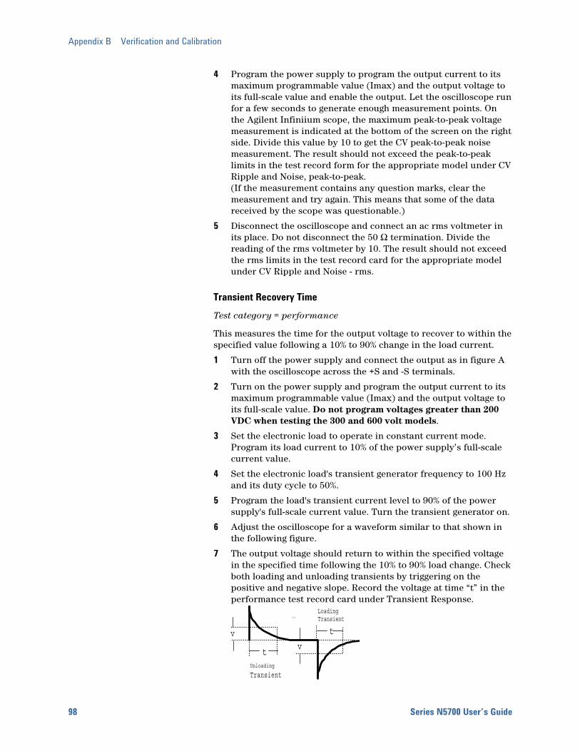
Appendix B Verification and Calibration
98 Series N5700 User’s Guide
4 Program the power supply to program the output current to its maximum programmable value (Imax) and the output voltage to its full-scale value and enable the output. Let the oscilloscope run for a few seconds to generate enough measurement points. On the Agilent Infiniium scope, the maximum peak-to-peak voltage measurement is indicated at the bottom of the screen on the right side. Divide this value by 10 to get the CV peak-to-peak noise measurement. The result should not exceed the peak-to-peak limits in the test record form for the appropriate model under CV Ripple and Noise, peak-to-peak. (If the measurement contains any question marks, clear the measurement and try again. This means that some of the data received by the scope was questionable.)
5 Disconnect the oscilloscope and connect an ac rms voltmeter in its place. Do not disconnect the 50 Ω termination. Divide the reading of the rms voltmeter by 10. The result should not exceed the rms limits in the test record card for the appropriate model under CV Ripple and Noise - rms.
Transient Recovery Time Test category = performance
This measures the time for the output voltage to recover to within the specified value following a 10% to 90% change in the load current.
1 Turn off the power supply and connect the output as in figure A with the oscilloscope across the +S and -S terminals.
2 Turn on the power supply and program the output current to its maximum programmable value (Imax) and the output voltage to its full-scale value. Do not program voltages greater than 200 VDC when testing the 300 and 600 volt models.
3 Set the electronic load to operate in constant current mode. Program its load current to 10% of the power supply’s full-scale current value.
4 Set the electronic load's transient generator frequency to 100 Hz and its duty cycle to 50%.
5 Program the load's transient current level to 90% of the power supply's full-scale current value. Turn the transient generator on.
6 Adjust the oscilloscope for a waveform similar to that shown in the following figure.
7 The output voltage should return to within the specified voltage in the specified time following the 10% to 90% load change. Check both loading and unloading transients by triggering on the positive and negative slope. Record the voltage at time “t” in the performance test record card under Transient Response.
tttt
t
v
LoadingTransient
Unloading
Transient
v
t

Verification and Calibration Appendix B
Series N5700 User’s Guide 99
Constant Current Tests
NOTE Refer to the appropriate test record form for the instrument settings of the model you are checking.
Current Programming and Readback Accuracy Test category = performance, calibration
This test verifies that the current programming and measurement functions are within specifications.
1 Turn off the power supply and connect the current shunt directly across the output. Connect the DVM across the current shunt.
2 Turn on the power supply and program the output voltage to its full-scale value and the output current to zero. The CC annunciator should be on and the output voltage reading should be approximately zero.
3 Divide the voltage drop (DVM reading) across the current shunt by its resistance to convert to amps and record this value (Iout). Also record the current reading on the front panel display. The readings should be within the limits specified in the test record card for the appropriate model under Current Programming and Readback @ 0 A.
4 Program the output current to its full-scale rating.
5 Divide the voltage drop (DVM reading) across the current shunt by its resistance to convert to amps and record this value (Iout). Also record the current reading on the front panel display. The readings should be within the limits specified in the test record card for the appropriate model under Current Programming and Readback @ Full Scale.
CC Load Effect Test category = performance
This test measures the change in output current resulting from a change in output voltage from full scale to short circuit.
1 Turn off the power supply and connect the current shunt, DVM, and electronic load as shown in figure B. Connect the DVM directly across the current shunt.
2 To ensure that the values read during this test are not the instantaneous measurement of the AC peaks of the output current ripple, several DC measurements should be made and averaged. If you are using an Agilent 3458A, you can set up the voltmeter to do this automatically. From the instrument’s front panel, program 100 power line cycles per measurement. Press NPLC 100 ENTER.
3 Turn on the power supply and program the output current to its full-scale value and the output voltage to its maximum programmable value (Vmax).
Appendix B Verification and Calibration
100 Series N5700 User’s Guide
4 With the electronic load in CV mode, set it for the output’s full-scale voltage. The CC annunciator on the front panel must be on. If it is not, adjust the load so that the voltage drops slightly.
5 Divide the voltage drop (DVM reading) across the current monitoring resistor by its resistance to convert to amps and record this value (Iout).
6 Short the electronic load. Divide the voltage drop (DVM reading) across the current shunt by its resistance to convert to amps and record this value (Iout). The difference in the current readings in steps 4 and 5 is the load effect, which should not exceed the value listed in the test record card for the appropriate model under CC Load Effect.
CC Source Effect Test category = performance
This test measures the change in output current that results from a change in AC line voltage from the minimum to maximum value within the line voltage specifications.
1 Turn off the power supply and connect the ac power line through a variable voltage transformer or AC source.
2 Connect the current shunt, DVM, and electronic load as shown in figure B. Connect the DVM directly across the current shunt. Set the variable voltage transformer to nominal line voltage.
3 To ensure that the values read during this test are not the instantaneous measurement of the AC peaks of the output current ripple, several DC measurements should be made and averaged. If you are using an Agilent 3458A, you can set up the voltmeter to do this automatically. From the instrument’s front panel, program 100 power line cycles per measurement. Press NPLC 100 ENTER.
4 Turn on the power supply and program the output current to its full-scale value and the output voltage to its maximum programmable value (Vmax).
5 With the electronic load in CV mode, set it for the output’s full-scale voltage. The CC annunciator on the front panel must be on. If it is not, adjust the load so that the voltage drops slightly.
6 Adjust the transformer to the lowest rated line voltage (85 VAC for 100/120 nominal line; 170 VAC for 200/240 nominal line).
7 Divide the voltage drop (DVM reading) across the current monitoring resistor by its resistance to convert to amps and record this value (Iout).
8 Adjust the transformer to the highest rated line voltage (132 VAC for 100/120 nominal line; 265 VAC for 200/240 nominal line).
9 Divide the voltage drop (DVM reading) across the current shunt by its resistance to convert to amps and record this value (Iout). The difference between the DVM reading in steps 6 and 8 is the source effect, which should not exceed the value listed in the test record card for the appropriate model under CC Source Effect.

Verification and Calibration Appendix B
Series N5700 User’s Guide 101
Test Record Form – Agilent N5741A and N5761A
Agilent N5741A and N5761A Report No _______________ Date __________________ Model Minimum Specs. Results Maximum Specs.Voltage Programming & Readback Minimum Voltage Vout Front Panel Display Readback High Voltage Vout Front Panel Display Readback
Both Both Both Both
− 3 mV
Vout − 6 mV 5.994 V
Vout − 12 mV
__________ __________ __________ __________
+ 3 mV
Vout + 6 mV 6.006 V
Vout + 12 mV CV Load Effect Both − 2.6 mV __________ + 2.6 mV CV Source Effect Both − 2.6 mV __________ + 2.6 mV CV Ripple and Noise peak-to-peak rms
Both Both
N/A N/A
__________ __________
60 mV 8 mV
Transient Response Voltage @ 1.5ms
Both
− 30 mV
__________
+ 30 mV
Current Programming & Readback Minimum Current Iout Front Panel Display Readback High Current Iout Front Panel Display Readback
N5741A N5761A N5741A N5761A N5741A N5761A N5741A N5761A
− 100 mA − 180 mA
Iout − 300 mA Iout − 540 mA
99.8 A 179.64 A
Iout − 400 mA Iout − 720 mA
__________ __________ __________ __________ __________ __________ __________ __________
+ 100 mA + 180 mA
Iout + 300 mA Iout + 540 mA
100.2 A 180.3 A
Iout + 400 mA Iout + 720 mA
CC Load Effect
N5741A N5761A
− 25 mA − 41 mA
__________ __________
+ 25 mA + 41 mA
CC Source Effect
N5741A N5761A
− 12 mA − 20 mA
__________ __________
+ 12 mA + 20 mA
Test Description N5741A Settings N5761A Settings Voltage Programming & Readback, Min Voltage 0 V, 0 A 0 V, 0 A Voltage Programming & Readback, High Voltage 6 V, 0 A 6 V, 0 A CV Load Effect, Source Effect, Ripple and Noise 6 V, 100 A 6 V, 180 A Transient Response 6 V, from 10 A to 90A 6 V, from 18 A to 172A Current Programming & Readback, Min Current 0 A, 6 V 0 A, 6 V Current Programming & Readback, High Current 100 A, 6 V 180 A, 6 V CC Load Effect, Source Effect 100 A, 6 V 180 A, 6 V
Load Requirements N5741A N5761A Current shunt 0.01Ω 100 A 0.001Ω 300 A Agilent N3300 Electronic load modules 2 – N3305A 3 – N3305A Fixed Resistor for CV Ripple and Noise 0.06Ω 1kW 0.03Ω 2kW

Appendix B Verification and Calibration
102 Series N5700 User’s Guide
Test Record Form – Agilent N5742A and N5762A
Agilent N5742A and N5762A Report No _______________ Date __________________ Description Model Minimum Specs. Results Maximum Specs.Voltage Programming & Readback Minimum Voltage Vout Front Panel Display Readback High Voltage Vout Front Panel Display Readback
Both Both Both Both
− 4 mV
Vout − 8 mV 7.992 V
Vout − 16 mV
__________ __________ __________ __________
+ 4 mV
Vout + 8 mV 8.008 V
Vout + 16 mV CV Load Effect Both − 2.8 mV __________ + 2.8 mV CV Source Effect Both − 2.8 mV __________ + 2.8 mV CV Ripple and Noise peak-to-peak rms
Both Both
N/A N/A
__________ __________
60 mV 8 mV
Transient Response Voltage @ 1.5ms
Both
− 40 mV
__________
+ 40 mV
Current Programming & Readback Minimum Current Iout Front Panel Display Readback High Current Iout Front Panel Display Readback
N5742A N5762A N5742A N5762A N5742A N5762A N5742A N5762A
− 90 mA − 165 mA
Iout − 270 mA Iout − 495 mA
89.82 A 164.67 A
Iout − 360 mA Iout − 660 mA
__________ __________ __________ __________ __________ __________ __________ __________
+ 90 mA
+ 165 mA Iout + 270 mA Iout + 495 mA
90.18 A 165.33 A
Iout + 360 mA Iout + 660 mA
CC Load Effect
N5742A N5762A
− 23 mA − 38 mA
__________ __________
+ 23 mA + 38 mA
CC Source Effect
N5742A N5762A
− 11 mA − 18.5 mA
__________ __________
+ 11 mA + 18.5 mA
Test Description N5742A Settings N5762A Settings Voltage Programming & Readback, Min Voltage 0 V, 0 A 0 V, 0 A Voltage Programming & Readback, High Voltage 8 V, 0 A 8 V, 0 A CV Load Effect, Source Effect, Ripple and Noise 8 V, 90 A 8 V, 165 A Transient Response 8 V, from 9 A to 81A 8 V, from 16.5 A to 148.5ACurrent Programming & Readback, Min Current 0 A, 8 V 0 A, 8 V Current Programming & Readback, High Current 90 A, 8 V 165 A, 8 V CC Load Effect, Source Effect 90 A, 8 V 165 A, 8 V
Load Requirements N5742A N5762A Current shunt 0.01Ω 100 A 0.001Ω 300 A Agilent N3300 Electronic load modules 2 – N3305A 3 – N3305A Fixed Resistor for CV Ripple and Noise 0.09Ω 1kW 0.04Ω 2kW
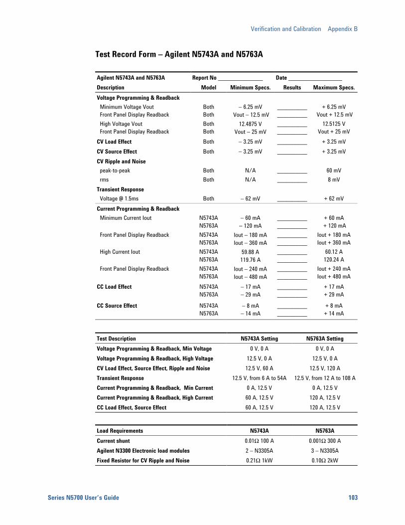
Verification and Calibration Appendix B
Series N5700 User’s Guide 103
Test Record Form – Agilent N5743A and N5763A
Agilent N5743A and N5763A Report No _______________ Date __________________ Description Model Minimum Specs. Results Maximum Specs.Voltage Programming & Readback Minimum Voltage Vout Front Panel Display Readback High Voltage Vout Front Panel Display Readback
Both Both Both Both
− 6.25 mV
Vout − 12.5 mV 12.4875 V
Vout − 25 mV
__________ __________ __________ __________
+ 6.25 mV
Vout + 12.5 mV 12.5125 V
Vout + 25 mV CV Load Effect Both − 3.25 mV __________ + 3.25 mV CV Source Effect Both − 3.25 mV __________ + 3.25 mV CV Ripple and Noise peak-to-peak rms
Both Both
N/A N/A
__________ __________
60 mV 8 mV
Transient Response Voltage @ 1.5ms
Both
− 62 mV
__________
+ 62 mV
Current Programming & Readback Minimum Current Iout Front Panel Display Readback High Current Iout Front Panel Display Readback
N5743A N5763A N5743A N5763A N5743A N5763A N5743A N5763A
− 60 mA − 120 mA
Iout − 180 mA Iout − 360 mA
59.88 A 119.76 A
Iout − 240 mA Iout − 480 mA
__________ __________ __________ __________ __________ __________ __________ __________
+ 60 mA
+ 120 mA Iout + 180 mA Iout + 360 mA
60.12 A 120.24 A
Iout + 240 mA Iout + 480 mA
CC Load Effect
N5743A N5763A
− 17 mA − 29 mA
__________ __________
+ 17 mA + 29 mA
CC Source Effect
N5743A N5763A
− 8 mA − 14 mA
__________ __________
+ 8 mA + 14 mA
Test Description N5743A Setting N5763A Setting Voltage Programming & Readback, Min Voltage 0 V, 0 A 0 V, 0 A Voltage Programming & Readback, High Voltage 12.5 V, 0 A 12.5 V, 0 A CV Load Effect, Source Effect, Ripple and Noise 12.5 V, 60 A 12.5 V, 120 A Transient Response 12.5 V, from 6 A to 54A 12.5 V, from 12 A to 108 ACurrent Programming & Readback, Min Current 0 A, 12.5 V 0 A, 12.5 V Current Programming & Readback, High Current 60 A, 12.5 V 120 A, 12.5 V CC Load Effect, Source Effect 60 A, 12.5 V 120 A, 12.5 V
Load Requirements N5743A N5763A Current shunt 0.01Ω 100 A 0.001Ω 300 A Agilent N3300 Electronic load modules 2 – N3305A 3 – N3305A Fixed Resistor for CV Ripple and Noise 0.21Ω 1kW 0.10Ω 2kW
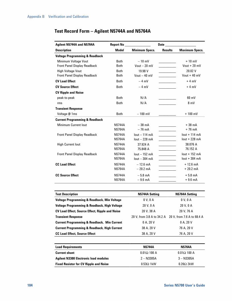
Appendix B Verification and Calibration
104 Series N5700 User’s Guide
Test Record Form – Agilent N5744A and N5764A
Agilent N5744A and N5764A Report No _______________ Date __________________ Description Model Minimum Specs. Results Maximum Specs.Voltage Programming & Readback Minimum Voltage Vout Front Panel Display Readback High Voltage Vout Front Panel Display Readback
Both Both Both Both
− 10 mV
Vout − 20 mV 19.98 V
Vout − 40 mV
__________ __________ __________ __________
+ 10 mV
Vout + 20 mV 20.02 V
Vout + 40 mV CV Load Effect Both − 4 mV __________ + 4 mV CV Source Effect Both − 4 mV __________ + 4 mV CV Ripple and Noise peak-to-peak rms
Both Both
N/A N/A
__________ __________
60 mV 8 mV
Transient Response Voltage @ 1ms
Both
− 100 mV
__________
+ 100 mV
Current Programming & Readback Minimum Current Iout Front Panel Display Readback High Current Iout Front Panel Display Readback
N5744A N5764A N5744A N5764A N5744A N5764A N5744A N5764A
− 38 mA − 76 mA
Iout − 114 mA Iout − 228 mA
37.924 A 75.848 A
Iout − 152 mA Iout − 304 mA
__________ __________ __________ __________ __________ __________ __________ __________
+ 38 mA + 76 mA
Iout + 114 mA Iout + 228 mA
38.076 A 76.152 A
Iout + 152 mA Iout + 304 mA
CC Load Effect
N5744A N5764A
− 12.6 mA − 20.2 mA
__________ __________
+ 12.6 mA + 20.2 mA
CC Source Effect
N5744A N5764A
− 5.8 mA − 9.6 mA
__________ __________
+ 5.8 mA + 9.6 mA
Test Description N5744A Setting N5764A Setting Voltage Programming & Readback, Min Voltage 0 V, 0 A 0 V, 0 A Voltage Programming & Readback, High Voltage 20 V, 0 A 20 V, 0 A CV Load Effect, Source Effect, Ripple and Noise 20 V, 38 A 20 V, 76 A Transient Response 20 V, from 3.8 A to 34.2 A 20 V, from 7.6 A to 68.4 ACurrent Programming & Readback, Min Current 0 A, 20 V 0 A, 20 V Current Programming & Readback, High Current 38 A, 20 V 76 A, 20 V CC Load Effect, Source Effect 38 A, 20 V 76 A, 20 V
Load Requirements N5744A N5764A Current shunt 0.01Ω 100 A 0.01Ω 100 A Agilent N3300 Electronic load modules 2 – N3305A 3 – N3305A Fixed Resistor for CV Ripple and Noise 0.53Ω 1kW 0.26Ω 2kW

Verification and Calibration Appendix B
Series N5700 User’s Guide 105
Test Record Form – Agilent N5745A and N5765A
Agilent N5745A and N5765A Report No _______________ Date __________________ Description Model Minimum Specs. Results Maximum Specs.Voltage Programming & Readback Minimum Voltage Vout Front Panel Display Readback High Voltage Vout Front Panel Display Readback
Both Both Both Both
− 15 mV
Vout − 30 mV 29.97 V
Vout − 60 mV
__________ __________ __________ __________
+ 15 mV
Vout + 30 mV 30.03 V
Vout + 60 mV CV Load Effect Both − 5 mV __________ + 5 mV CV Source Effect Both − 5 mV __________ + 5 mV CV Ripple and Noise peak-to-peak rms
Both Both
N/A N/A
__________ __________
60 mV 8 mV
Transient Response Voltage @ 1ms
Both
− 150 mV
__________
+ 150 mV
Current Programming & Readback Minimum Current Iout Front Panel Display Readback High Current Iout Front Panel Display Readback
N5745A N5765A N5745A N5765A N5745A N5765A N5745A N5765A
− 25 mA − 50 mA
Iout − 75 mA Iout − 150 mA
24.95 A 49.9 A
Iout − 100 mA Iout − 200 mA
__________ __________ __________ __________ __________ __________ __________ __________
+ 25 mA + 50 mA
Iout + 75 mA Iout + 150 mA
25.05 A 50.1 A
Iout + 100 mA Iout + 200 mA
CC Load Effect
N5745A N5765A
− 10 mA − 15 mA
__________ __________
+ 10 mA + 15 mA
CC Source Effect
N5745A N5765A
− 4.5 mA − 7 mA
__________ __________
+ 4.5 mA + 7 mA
Test Description N5745A Setting N5765A Setting Voltage Programming & Readback, Min Voltage 0 V, 0 A 0 V, 0 A Voltage Programming & Readback, High Voltage 30 V, 0 A 30 V, 0 A CV Load Effect, Source Effect, Ripple and Noise 30 V, 25 A 30 V, 50 A Transient Response 30 V, from 2.5 A to 22.5 A 30 V, from 5 A to 45 A Current Programming & Readback, Min Current 0 A, 30 V 0 A, 30 V Current Programming & Readback, High Current 25 A, 30 V 50 A, 30 V CC Load Effect, Source Effect 25 A, 30 V 50 A, 30 V
Load Requirements N5745A N5765A Current shunt 0.01Ω 100 A 0.01Ω 100 A Agilent N3300 Electronic load modules 2 – N3305A 3 – N3305A Fixed Resistor for CV Ripple and Noise 1.20Ω 1kW 0.60Ω 2kW
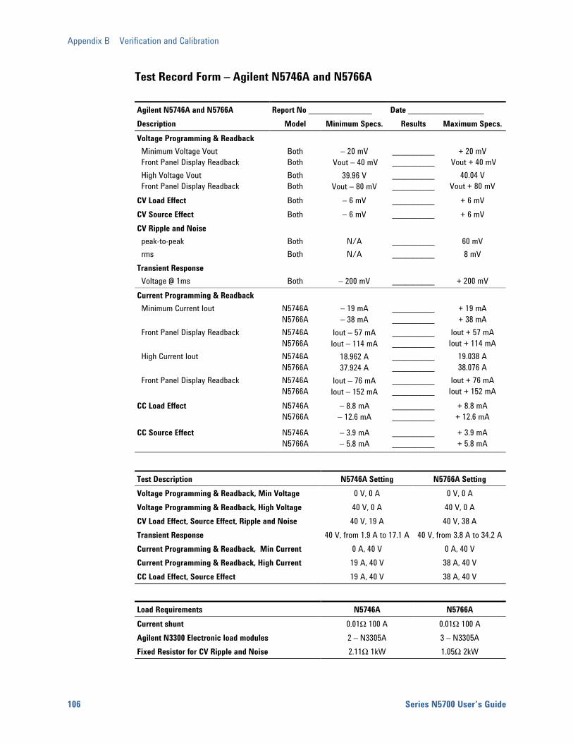
Appendix B Verification and Calibration
106 Series N5700 User’s Guide
Test Record Form – Agilent N5746A and N5766A
Agilent N5746A and N5766A Report No _______________ Date __________________ Description Model Minimum Specs. Results Maximum Specs.Voltage Programming & Readback Minimum Voltage Vout Front Panel Display Readback High Voltage Vout Front Panel Display Readback
Both Both Both Both
− 20 mV
Vout − 40 mV 39.96 V
Vout − 80 mV
__________ __________ __________ __________
+ 20 mV
Vout + 40 mV 40.04 V
Vout + 80 mV CV Load Effect Both − 6 mV __________ + 6 mV CV Source Effect Both − 6 mV __________ + 6 mV CV Ripple and Noise peak-to-peak rms
Both Both
N/A N/A
__________ __________
60 mV 8 mV
Transient Response Voltage @ 1ms
Both
− 200 mV
__________
+ 200 mV
Current Programming & Readback Minimum Current Iout Front Panel Display Readback High Current Iout Front Panel Display Readback
N5746A N5766A N5746A N5766A N5746A N5766A N5746A N5766A
− 19 mA − 38 mA
Iout − 57 mA Iout − 114 mA
18.962 A 37.924 A
Iout − 76 mA Iout − 152 mA
__________ __________ __________ __________ __________ __________ __________ __________
+ 19 mA + 38 mA
Iout + 57 mA Iout + 114 mA
19.038 A 38.076 A
Iout + 76 mA Iout + 152 mA
CC Load Effect
N5746A N5766A
− 8.8 mA − 12.6 mA
__________ __________
+ 8.8 mA + 12.6 mA
CC Source Effect
N5746A N5766A
− 3.9 mA − 5.8 mA
__________ __________
+ 3.9 mA + 5.8 mA
Test Description N5746A Setting N5766A Setting Voltage Programming & Readback, Min Voltage 0 V, 0 A 0 V, 0 A Voltage Programming & Readback, High Voltage 40 V, 0 A 40 V, 0 A CV Load Effect, Source Effect, Ripple and Noise 40 V, 19 A 40 V, 38 A Transient Response 40 V, from 1.9 A to 17.1 A 40 V, from 3.8 A to 34.2 ACurrent Programming & Readback, Min Current 0 A, 40 V 0 A, 40 V Current Programming & Readback, High Current 19 A, 40 V 38 A, 40 V CC Load Effect, Source Effect 19 A, 40 V 38 A, 40 V
Load Requirements N5746A N5766A Current shunt 0.01Ω 100 A 0.01Ω 100 A Agilent N3300 Electronic load modules 2 – N3305A 3 – N3305A Fixed Resistor for CV Ripple and Noise 2.11Ω 1kW 1.05Ω 2kW
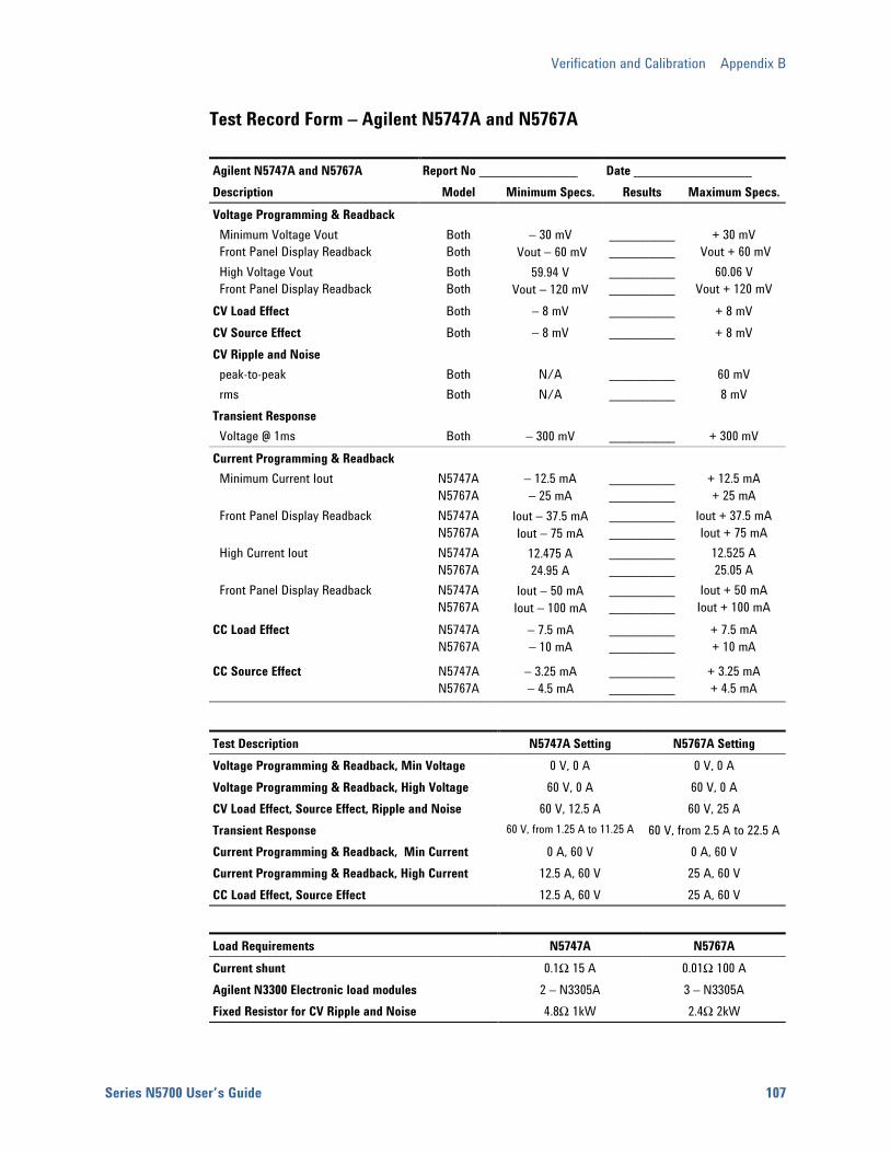
Verification and Calibration Appendix B
Series N5700 User’s Guide 107
Test Record Form – Agilent N5747A and N5767A
Agilent N5747A and N5767A Report No _______________ Date __________________ Description Model Minimum Specs. Results Maximum Specs.Voltage Programming & Readback Minimum Voltage Vout Front Panel Display Readback High Voltage Vout Front Panel Display Readback
Both Both Both Both
− 30 mV
Vout − 60 mV 59.94 V
Vout − 120 mV
__________ __________ __________ __________
+ 30 mV
Vout + 60 mV 60.06 V
Vout + 120 mV CV Load Effect Both − 8 mV __________ + 8 mV CV Source Effect Both − 8 mV __________ + 8 mV CV Ripple and Noise peak-to-peak rms
Both Both
N/A N/A
__________ __________
60 mV 8 mV
Transient Response Voltage @ 1ms
Both
− 300 mV
__________
+ 300 mV
Current Programming & Readback Minimum Current Iout Front Panel Display Readback High Current Iout Front Panel Display Readback
N5747A N5767A N5747A N5767A N5747A N5767A N5747A N5767A
− 12.5 mA − 25 mA
Iout − 37.5 mA Iout − 75 mA
12.475 A 24.95 A
Iout − 50 mA Iout − 100 mA
__________ __________ __________ __________ __________ __________ __________ __________
+ 12.5 mA + 25 mA
Iout + 37.5 mA Iout + 75 mA
12.525 A 25.05 A
Iout + 50 mA Iout + 100 mA
CC Load Effect
N5747A N5767A
− 7.5 mA − 10 mA
__________ __________
+ 7.5 mA + 10 mA
CC Source Effect
N5747A N5767A
− 3.25 mA − 4.5 mA
__________ __________
+ 3.25 mA + 4.5 mA
Test Description N5747A Setting N5767A Setting Voltage Programming & Readback, Min Voltage 0 V, 0 A 0 V, 0 A Voltage Programming & Readback, High Voltage 60 V, 0 A 60 V, 0 A CV Load Effect, Source Effect, Ripple and Noise 60 V, 12.5 A 60 V, 25 A Transient Response 60 V, from 1.25 A to 11.25 A 60 V, from 2.5 A to 22.5 ACurrent Programming & Readback, Min Current 0 A, 60 V 0 A, 60 V Current Programming & Readback, High Current 12.5 A, 60 V 25 A, 60 V CC Load Effect, Source Effect 12.5 A, 60 V 25 A, 60 V
Load Requirements N5747A N5767A Current shunt 0.1Ω 15 A 0.01Ω 100 A Agilent N3300 Electronic load modules 2 – N3305A 3 – N3305A Fixed Resistor for CV Ripple and Noise 4.8Ω 1kW 2.4Ω 2kW

Appendix B Verification and Calibration
108 Series N5700 User’s Guide
Test Record Form – Agilent N5748A and N5768A
Agilent N5748A and N5768A Report No _______________ Date __________________ Description Model Minimum Specs. Results Maximum Specs.Voltage Programming & Readback Minimum Voltage Vout Front Panel Display Readback High Voltage Vout Front Panel Display Readback
Both Both Both Both
− 40 mV
Vout − 80 mV 79.92 V
Vout − 160 mV
__________ __________ __________ __________
+ 40 mV
Vout + 80 mV 80.08 V
Vout + 160 mV CV Load Effect Both − 10 mV __________ + 10 mV CV Source Effect Both − 10 mV __________ + 10 mV CV Ripple and Noise peak-to-peak rms
Both Both
N/A N/A
__________ __________
80 mV 8 mV
Transient Response Voltage @ 1ms
Both
− 400 mV
__________
+ 400 mV
Current Programming & Readback Minimum Current Iout Front Panel Display Readback High Current Iout Front Panel Display Readback
N5748A N5768A N5748A N5768A N5748A N5768A N5748A N5768A
− 9.5 mA − 19 mA
Iout − 28.5 mA Iout − 57 mA
9.481 A 18.962 A
Iout − 38 mA Iout − 76 mA
__________ __________ __________ __________ __________ __________ __________ __________
+ 9.5 mA + 19 mA
Iout + 28.5 mA Iout + 57 mA
9.519 A 19.038 A
Iout + 38 mA Iout + 76 mA
CC Load Effect
N5748A N5768A
− 6.9 mA − 8.8 mA
__________ __________
+ 6.9 mA + 8.8 mA
CC Source Effect
N5748A N5768A
− 2.95 mA − 3.9 mA
__________ __________
+ 2.95 mA + 3.9 mA
Test Description N5748A Setting N5768A Setting Voltage Programming & Readback, Min Voltage 0 V, 0 A 0 V, 0 A Voltage Programming & Readback, High Voltage 80 V, 0 A 80 V, 0 A CV Load Effect, Source Effect, Ripple and Noise 80 V, 9.5 A 80 V, 19 A Transient Response 80 V, from 0.95 A to 8.55 A 80 V, from 1.9 A to 17.1 ACurrent Programming & Readback, Min Current 0 A, 80 V 0 A, 80 V Current Programming & Readback, High Current 9.5 A, 80 V 19 A, 80 V CC Load Effect, Source Effect 9.5 A, 80 V 19 A, 80 V
Load Requirements N5748A N5768A Current shunt 0.1Ω 15 A 0.01Ω 100 A Agilent N3300 Electronic load modules 2 – N3305A 3 – N3305A Fixed Resistor for CV Ripple and Noise 8.42Ω 1kW 4.21Ω 2kW

Verification and Calibration Appendix B
Series N5700 User’s Guide 109
Test Record Form – Agilent N5749A and N5769A
Agilent N5749A and N5769A Report No _______________ Date __________________ Description Model Minimum Specs. Results Maximum Specs.Voltage Programming & Readback Minimum Voltage Vout Front Panel Display Readback High Voltage Vout Front Panel Display Readback
Both Both Both Both
− 50 mV
Vout − 100 mV 99.9 V
Vout − 200 mV
__________ __________ __________ __________
+ 50 mV
Vout + 100 mV 100.1 V
Vout + 200 mV CV Load Effect Both − 12 mV __________ + 12 mV CV Source Effect Both − 12 mV __________ + 12 mV CV Ripple and Noise peak-to-peak rms
Both Both
N/A N/A
__________ __________
80 mV 8 mV
Transient Response Voltage @ 1ms
Both
− 500 mV
__________
+ 500 mV
Current Programming & Readback Minimum Current Iout Front Panel Display Readback High Current Iout Front Panel Display Readback
N5749A N5769A N5749A N5769A N5749A N5769A N5749A N5769A
− 7.5 mA − 15 mA
Iout − 22.5 mA Iout − 45 mA
7.485 A 14.97 A
Iout − 30 mA Iout − 60 mA
__________ __________ __________ __________ __________ __________ __________ __________
+ 7.5 mA + 15 mA
Iout + 22.5 mA Iout + 45 mA
7.515 A 15.03 A
Iout + 30 mA Iout + 60 mA
CC Load Effect
N5749A N5769A
− 6.5 mA − 8 mA
__________ __________
+ 6.5 mA + 8 mA
CC Source Effect
N5749A N5769A
− 2.75 mA − 3.5 mA
__________ __________
+ 2.75 mA + 3.5 mA
Test Description N5749A Setting N5769A Setting Voltage Programming & Readback, Min Voltage 0 V, 0 A 0 V, 0 A Voltage Programming & Readback, High Voltage 100 V, 0 A 100 V, 0 A CV Load Effect, Source Effect, Ripple and Noise 100 V, 7.5 A 100 V, 15 A Transient Response 100 V, from 0.75 A to 6.75 A 100 V, from 1.5 A to 13.5 ACurrent Programming & Readback, Min Current 0 A, 100 V 0 A, 100 V Current Programming & Readback, High Current 7.5 A, 100 V 15 A, 100 V CC Load Effect, Source Effect 7.5 A, 100 V 15 A, 100 V
Load Requirements N5749A N5769A Current shunt 0.1Ω 15 A 0.1Ω 15 A Agilent N3300 Electronic load modules 2 – N3305A 3 – N3305A Fixed Resistor for CV Ripple and Noise 13.33Ω 1kW 6.67Ω 2kW

Appendix B Verification and Calibration
110 Series N5700 User’s Guide
Test Record Form – Agilent N5750A and N5770A
Agilent N5750A and N5770A Report No _______________ Date __________________ Description Model Minimum Specs. Results Maximum Specs.Voltage Programming & Readback Minimum Voltage Vout Front Panel Display Readback High Voltage Vout Front Panel Display Readback
Both Both Both Both
− 75 mV
Vout − 150 mV 149.85 V
Vout − 300 mV
__________ __________ __________ __________
+ 75 mV
Vout + 150 mV 150.15 V
Vout + 300 mV CV Load Effect Both − 17 mV __________ + 17 mV CV Source Effect Both − 17 mV __________ + 17 mV CV Ripple and Noise peak-to-peak rms
Both Both
N/A N/A
__________ __________
100 mV 12 mV
Transient Response Voltage @ 2ms
Both
− 750 mV
__________
+ 750 mV
Current Programming & Readback Minimum Current Iout Front Panel Display Readback High Current Iout Front Panel Display Readback
N5750A N5770A N5750A N5770A N5750A N5770A N5750A N5770A
− 5 mA − 10 mA
Iout − 15 mA Iout − 30 mA
4.99 A 9.98 A
Iout − 20 mA Iout − 40 mA
__________ __________ __________ __________ __________ __________ __________ __________
+ 5 mA + 10 mA
Iout + 15 mA Iout + 30 mA
5.01 A 10.02 A
Iout + 20 mA Iout + 40 mA
CC Load Effect
N5750A N5770A
− 6 mA − 7 mA
__________ __________
+ 6 mA + 7 mA
CC Source Effect
N5750A N5770A
− 2.5 mA − 3 mA
__________ __________
+ 2.5 mA + 3 mA
Test Description N5750A Setting N5770A Setting Voltage Programming & Readback, Min Voltage 0 V, 0 A 0 V, 0 A Voltage Programming & Readback, High Voltage 150 V, 0 A 150 V, 0 A CV Load Effect, Source Effect, Ripple and Noise 150 V, 5 A 150 V, 10 A Transient Response 150 V, from 0.5 A to 4.5 A 150 V, from 1 A to 9 A Current Programming & Readback, Min Current 0 A, 150 V 0 A, 150 V Current Programming & Readback, High Current 5 A, 150 V 10 A, 150 V CC Load Effect, Source Effect 5 A, 150 V 10 A, 150 V
Load Requirements N5750A N5770A Current shunt 0.1Ω 15 A 0.1Ω 15 A Agilent N3300 Electronic load modules 2 – N3305A 3 – N3305A Fixed Resistor for CV Ripple and Noise 30.0Ω 1kW 15.0Ω 2kW

Verification and Calibration Appendix B
Series N5700 User’s Guide 111
Test Record Form – Agilent N5751A and N5771A
Agilent N5751A and N5771A Report No _______________ Date __________________ Description Model Minimum Specs. Results Maximum Specs.Voltage Programming & Readback Minimum Voltage Vout Front Panel Display Readback High Voltage Vout Front Panel Display Readback
Both Both Both Both
− 150 mV
Vout − 300 mV 299.7 V
Vout − 600 mV
__________ __________ __________ __________
+ 150 mV
Vout + 300 mV 300.3 V
Vout + 600 mV CV Load Effect Both − 32 mV __________ + 32 mV CV Source Effect Both − 32 mV __________ + 32 mV CV Ripple and Noise peak-to-peak rms
Both Both
N/A N/A
__________ __________
150 mV 20 mV
Transient Response Voltage @ 2ms
Both
− 1 V
__________
+ 1 V
Current Programming & Readback Minimum Current Iout Front Panel Display Readback High Current Iout Front Panel Display Readback
N5751A N5771A N5751A N5771A N5751A N5771A N5751A N5771A
− 2.5 mA − 5 mA
Iout − 7.5 mA Iout − 15 mA
2.495 A 4.99 A
Iout − 10 mA Iout − 20 mA
__________ __________ __________ __________ __________ __________ __________ __________
+ 2.5 mA + 5 mA
Iout + 7.5 mA Iout + 15 mA
2.505 A 5.01 A
Iout + 10 mA Iout + 20 mA
CC Load Effect
N5751A N5771A
− 5.5 mA − 6 mA
__________ __________
+ 5.5 mA + 6 mA
CC Source Effect
N5751A N5771A
− 2.25 mA − 2.5 mA
__________ __________
+ 2.25 mA + 2.5 mA
Test Description N5751A Setting N5771A Setting Voltage Programming & Readback, Min Voltage 0 V, 0 A 0 V, 0 A Voltage Programming & Readback, High Voltage 300 V, 0 A 300 V, 0 A CV Load Effect, Source Effect, Ripple and Noise 300 V, 2.5 A 300 V, 5 A Transient Response 200 V, from 0.25 A to 2.25 A 200 V, from 0.5 A to 4.5 ACurrent Programming & Readback, Min Current 0 A, 300 V 0 A, 300 V Current Programming & Readback, High Current 2.5 A, 300 V 5 A, 300 V CC Load Effect, Source Effect 2.5 A, 300 V 5 A, 300 V
Load Requirements N5751A N5771A Current shunt 0.1Ω 15 A 0.1Ω 15 A Use fixed resistor instead of load modules 120Ω 1kW 60Ω 2kW Fixed Resistor for CV Ripple and Noise 120Ω 1kW 60Ω 2kW

Appendix B Verification and Calibration
112 Series N5700 User’s Guide
Test Record Form – Agilent N5752A and N5772A
Agilent N5752A and N5772A Report No _______________ Date __________________ Description Model Minimum Specs. Results Maximum Specs.Voltage Programming & Readback Minimum Voltage Vout Front Panel Display Readback High Voltage Vout Front Panel Display Readback
Both Both Both Both
− 300 mV
Vout − 600 mV 599.4 V
Vout − 1.2 V
__________ __________ __________ __________
+ 300 mV
Vout + 600 mV 600.6 V
Vout + 1.2 V CV Load Effect Both − 62 mV __________ + 62 mV CV Source Effect Both − 62 mV __________ + 62 mV CV Ripple and Noise peak-to-peak rms
Both Both
N/A N/A
__________ __________
300 mV 60 mV
Transient Response Voltage @ 2ms
Both
− 1 V
__________
+ 1 V
Current Programming & Readback Minimum Current Iout Front Panel Display Readback High Current Iout Front Panel Display Readback
N5752A N5772A N5752A N5772A N5752A N5772A N5752A N5772A
− 1.3 mA − 2.6 mA
Iout − 3.9 mA Iout − 7.8 mA
1.2974 A 2.5948 A
Iout − 5.2 mA Iout − 10.4 mA
__________ __________ __________ __________ __________ __________ __________ __________
+ 1.3 mA + 2.6 mA
Iout + 3.9 mA Iout + 7.8 mA
1.3026 A 2.6052 A
Iout + 5.2 mA Iout + 10.4 mA
CC Load Effect
N5752A N5772A
− 5.26 mA − 5.5 mA
__________ __________
+ 5.26 mA + 5.5 mA
CC Source Effect
N5752A N5772A
− 2.13 mA − 2.26 mA
__________ __________
+ 2.13 mA + 2.26 mA
Test Description N5752A Setting N5772A Setting Voltage Programming & Readback, Min Voltage 0 V, 0 A 0 V, 0 A Voltage Programming & Readback, High Voltage 600 V, 0 A 600 V, 0 A CV Load Effect, Source Effect, Ripple and Noise 600 V, 1.3 A 600 V, 2.6 A Transient Response 200 V, from 0.13 A to 1.17 A 200 V, from 0.26 A to 2.34 A
Current Programming & Readback, Min Current 0 A, 600 V 0 A, 600 V Current Programming & Readback, High Current 1.3 A, 600 V 2.6 A, 600 V CC Load Effect, Source Effect 1.3 A, 600 V 2.6 A, 600 V
Load Requirements N5752A N5772A Current shunt 0.1Ω 15 A 0.1Ω 15 A Use fixed resistor instead of load modules 462Ω 1kW 231Ω 2kW Fixed Resistor for CV Ripple and Noise 462Ω 1kW 231Ω 2kW
Verification and Calibration Appendix B
Series N5700 User’s Guide 113
Calibration Refer to the “Equipment Required” section in this appendix for a list of the equipment required for calibration. A general outline of the procedure is as follows:
Enter the calibration mode by providing the correct password. The password is set at the factory to the model number. Once calibration has been entered, the password can be changed by the user. lf the password is incorrect, an error occurs.
You do not have to do a complete calibration. If appropriate, you may calibrate only the voltage or current functions and then save the calibration constants.
As each calibration sequence is completed, the instrument saves the calibration constants and begins using them.
Exit the calibration mode. Note that a Reset command also sets the calibration state to OFF.
Calibration Procedure Unless instructed otherwise, connect the +sense terminal to the +output, and the -sense terminal to the -output.
When calibrating the unit using SCPI commands, most calibration steps involve sending an *OPC? query to synchronize with the power supply’s command completion before proceeding. The response from the instrument must be read each time *OPC? is given.
NOTE The CAL:LEV and CAL:DATA commands may take several seconds to complete. If a timeout occurs in your VISA application, you may need to change the VI_ATTR_TMO_VALUE in the ViSetAttribute function.
Enable Calibration mode *RST
OUTP ON
CAL:STAT ON, <password>
Voltage Programming and Measurement Calibration Step 1. Connect the Agilent 3458A voltage input to an output.
Step 2. Select the full-scale voltage programming range. The value to program a range must be the maximum voltage of the range.
CAL:VOLT <voltage>
Step 3. Select the first voltage calibration point.
CAL:LEV P1

Appendix B Verification and Calibration
114 Series N5700 User’s Guide
*OPC?
Step 4. Measure the output voltage with the Agilent 3458A and enter the data.
CAL:DATA <data>
Step 5. Select the second voltage calibration point.
CAL:LEV P2
*OPC?
Step 6. Measure the output voltage with the Agilent 3458A and enter the data.
CAL:DATA <data>
Current Programming and Measurement Calibration Step 1. Connect a precision shunt resistor to an output. Connect the Agilent
3458A to measure the voltage across the shunt. The shunt resistor should be suitable for measuring at least 120% of the power supply’s rated full-scale current.
Step 2. Select the full-scale current programming range. The value to program a range must be the maximum current of the range.
CAL:CURR <current>
Step 3. Select the first current calibration point.
CAL:LEV P1
*OPC?
Step 4. Calculate the shunt current (I=V/R) and enter the data.
CAL:DATA <data>
Step 5. Select the second current calibration point.
CAL:LEV P2
*OPC?
Step 6. Calculate the shunt current (I=V/R) and enter the data.
CAL:DATA <data>
Exit Calibration mode CAL:STAT OFF
Series N5700 User’s Guide 115
Appendix C Service Types of Service Available.............................................................................116 Repackaging for Shipment.............................................................................116 Operating Checklist.........................................................................................116 Error Messages ...............................................................................................118
This chapter discusses the procedures involved for returning a failed instrument to Agilent Technologies for service or repair. A procedure is included for diagnosing specific symptoms. Actual repair is done through unit exchange.

Appendix C Service
116 Series N5700 User’s Guide
Types of Service Available If your instrument fails during the warranty period, Agilent Technologies will replace or repair it free of charge. After your warranty expires, Agilent Technologies will replace or repair it at a competitive price. The standard repair process is “whole unit exchange”. The replacement units are fully refurbished and are shipped with new calibration certificates.
Contact your nearest Agilent Technologies Service Center. They will arrange to have your instrument repaired or replaced.
Repackaging for Shipment If the unit is to be shipped to Agilent Technologies for service or repair, be sure to:
Attach a tag to the unit identifying the owner and indicating the required service or repair. Include the model number and full serial number.
Place the unit in its original container with appropriate packaging material for shipping.
Secure the container with strong tape or metal bands.
If the original shipping container is not available, place your unit in a container that will ensure at least 4 inches of compressible packaging material around all sides for the instrument. Use static-free packaging materials to avoid additional damage to your unit.
Agilent Technologies suggests that you always insure shipments.
Operating Checklist If the power supply appears to be operating improperly, use the following procedures to determine whether the power supply, load, or external circuits are the cause.
Turn-on check out procedure Turn off the unit and remove all external connections to the instrument. Follow the turn-on checkout procedure in chapter 2.
Trouble-shooting guide If you have encountered problems during the checkout procedure, use the following guide to diagnose a specific symptom. If the action does not remedy the problem, return the unit for service.
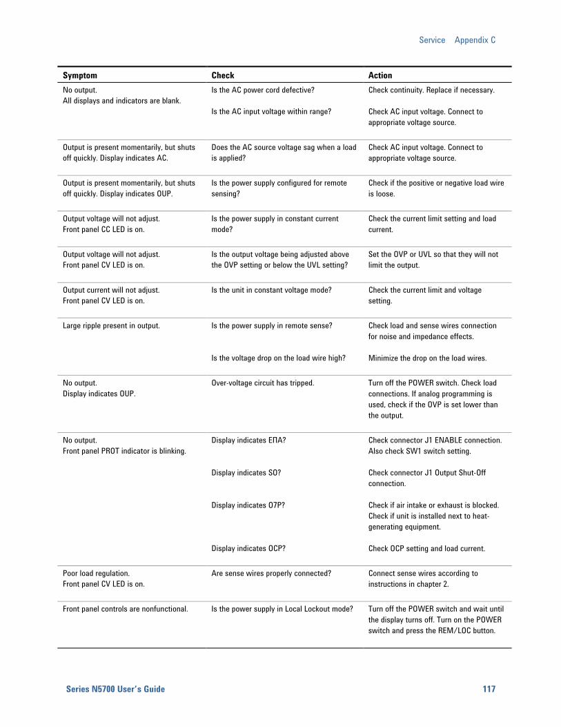
Service Appendix C
Series N5700 User’s Guide 117
Symptom Check Action No output. All displays and indicators are blank.
Is the AC power cord defective? Is the AC input voltage within range?
Check continuity. Replace if necessary. Check AC input voltage. Connect to appropriate voltage source.
Output is present momentarily, but shuts off quickly. Display indicates AC.
Does the AC source voltage sag when a load is applied?
Check AC input voltage. Connect to appropriate voltage source.
Output is present momentarily, but shuts off quickly. Display indicates OUP.
Is the power supply configured for remote sensing?
Check if the positive or negative load wire is loose.
Output voltage will not adjust. Front panel CC LED is on.
Is the power supply in constant current mode?
Check the current limit setting and load current.
Output voltage will not adjust. Front panel CV LED is on.
Is the output voltage being adjusted above the OVP setting or below the UVL setting?
Set the OVP or UVL so that they will not limit the output.
Output current will not adjust. Front panel CV LED is on.
Is the unit in constant voltage mode? Check the current limit and voltage setting.
Large ripple present in output. Is the power supply in remote sense? Is the voltage drop on the load wire high?
Check load and sense wires connection for noise and impedance effects. Minimize the drop on the load wires.
No output. Display indicates OUP.
Over-voltage circuit has tripped. Turn off the POWER switch. Check load connections. If analog programming is used, check if the OVP is set lower than the output.
No output. Front panel PROT indicator is blinking.
Display indicates EΠA? Display indicates SO? Display indicates O7P? Display indicates OCP?
Check connector J1 ENABLE connection. Also check SW1 switch setting. Check connector J1 Output Shut-Off connection. Check if air intake or exhaust is blocked. Check if unit is installed next to heat-generating equipment. Check OCP setting and load current.
Poor load regulation. Front panel CV LED is on.
Are sense wires properly connected? Connect sense wires according to instructions in chapter 2.
Front panel controls are nonfunctional. Is the power supply in Local Lockout mode? Turn off the POWER switch and wait until the display turns off. Turn on the POWER switch and press the REM/LOC button.
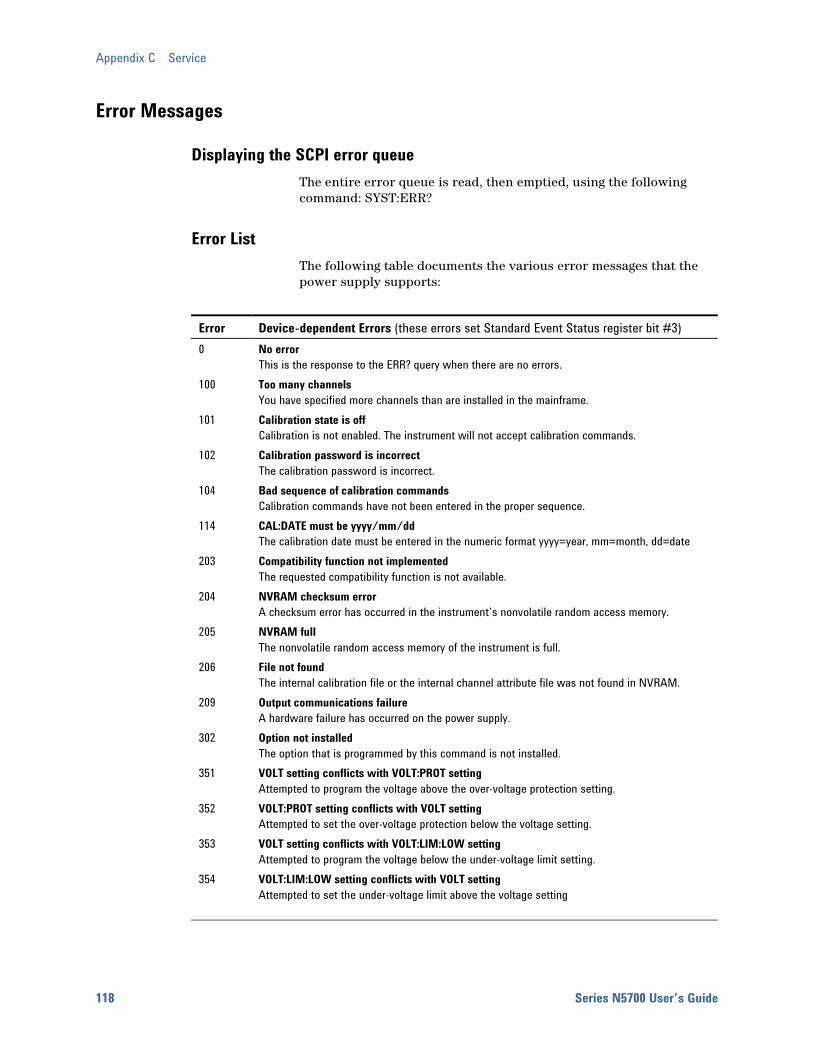
Appendix C Service
118 Series N5700 User’s Guide
Error Messages
Displaying the SCPI error queue The entire error queue is read, then emptied, using the following command: SYST:ERR?
Error List The following table documents the various error messages that the power supply supports:
Error Device-dependent Errors (these errors set Standard Event Status register bit #3) 0 No error
This is the response to the ERR? query when there are no errors. 100 Too many channels
You have specified more channels than are installed in the mainframe. 101 Calibration state is off
Calibration is not enabled. The instrument will not accept calibration commands. 102 Calibration password is incorrect
The calibration password is incorrect. 104 Bad sequence of calibration commands
Calibration commands have not been entered in the proper sequence. 114 CAL:DATE must be yyyy/mm/dd
The calibration date must be entered in the numeric format yyyy=year, mm=month, dd=date 203 Compatibility function not implemented
The requested compatibility function is not available. 204 NVRAM checksum error
A checksum error has occurred in the instrument’s nonvolatile random access memory. 205 NVRAM full
The nonvolatile random access memory of the instrument is full. 206 File not found
The internal calibration file or the internal channel attribute file was not found in NVRAM. 209 Output communications failure
A hardware failure has occurred on the power supply. 302 Option not installed
The option that is programmed by this command is not installed. 351 VOLT setting conflicts with VOLT:PROT setting
Attempted to program the voltage above the over-voltage protection setting. 352 VOLT:PROT setting conflicts with VOLT setting
Attempted to set the over-voltage protection below the voltage setting. 353 VOLT setting conflicts with VOLT:LIM:LOW setting
Attempted to program the voltage below the under-voltage limit setting. 354 VOLT:LIM:LOW setting conflicts with VOLT setting
Attempted to set the under-voltage limit above the voltage setting
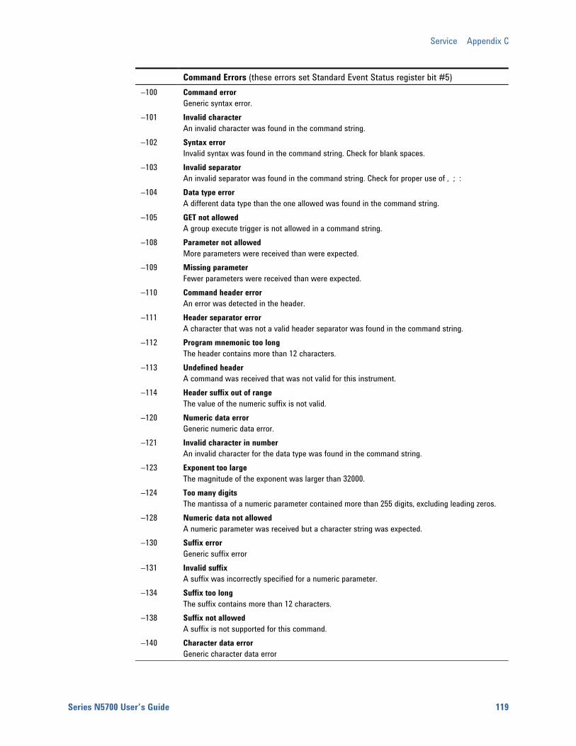
Service Appendix C
Series N5700 User’s Guide 119
Command Errors (these errors set Standard Event Status register bit #5) −100 Command error
Generic syntax error. −101 Invalid character
An invalid character was found in the command string. −102 Syntax error
Invalid syntax was found in the command string. Check for blank spaces. −103 Invalid separator
An invalid separator was found in the command string. Check for proper use of , ; : −104 Data type error
A different data type than the one allowed was found in the command string. −105 GET not allowed
A group execute trigger is not allowed in a command string. −108 Parameter not allowed
More parameters were received than were expected. −109 Missing parameter
Fewer parameters were received than were expected. −110 Command header error
An error was detected in the header. −111 Header separator error
A character that was not a valid header separator was found in the command string. −112 Program mnemonic too long
The header contains more than 12 characters. −113 Undefined header
A command was received that was not valid for this instrument. −114 Header suffix out of range
The value of the numeric suffix is not valid. −120 Numeric data error
Generic numeric data error. −121 Invalid character in number
An invalid character for the data type was found in the command string. −123 Exponent too large
The magnitude of the exponent was larger than 32000. −124 Too many digits
The mantissa of a numeric parameter contained more than 255 digits, excluding leading zeros. −128 Numeric data not allowed
A numeric parameter was received but a character string was expected. −130 Suffix error
Generic suffix error −131 Invalid suffix
A suffix was incorrectly specified for a numeric parameter. −134 Suffix too long
The suffix contains more than 12 characters. −138 Suffix not allowed
A suffix is not supported for this command. −140 Character data error
Generic character data error
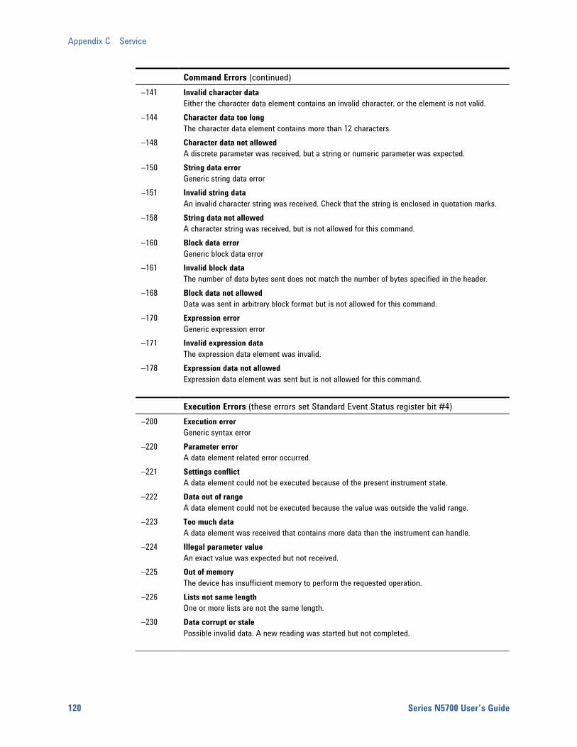
Appendix C Service
120 Series N5700 User’s Guide
Command Errors (continued) −141 Invalid character data
Either the character data element contains an invalid character, or the element is not valid. −144 Character data too long
The character data element contains more than 12 characters. −148 Character data not allowed
A discrete parameter was received, but a string or numeric parameter was expected. −150 String data error
Generic string data error −151 Invalid string data
An invalid character string was received. Check that the string is enclosed in quotation marks. −158 String data not allowed
A character string was received, but is not allowed for this command. −160 Block data error
Generic block data error −161 Invalid block data
The number of data bytes sent does not match the number of bytes specified in the header. −168 Block data not allowed
Data was sent in arbitrary block format but is not allowed for this command. −170 Expression error
Generic expression error −171 Invalid expression data
The expression data element was invalid. −178 Expression data not allowed
Expression data element was sent but is not allowed for this command.
Execution Errors (these errors set Standard Event Status register bit #4) −200 Execution error
Generic syntax error −220 Parameter error
A data element related error occurred. −221 Settings conflict
A data element could not be executed because of the present instrument state. −222 Data out of range
A data element could not be executed because the value was outside the valid range. −223 Too much data
A data element was received that contains more data than the instrument can handle. −224 Illegal parameter value
An exact value was expected but not received. −225 Out of memory
The device has insufficient memory to perform the requested operation. −226 Lists not same length
One or more lists are not the same length. −230 Data corrupt or stale
Possible invalid data. A new reading was started but not completed.
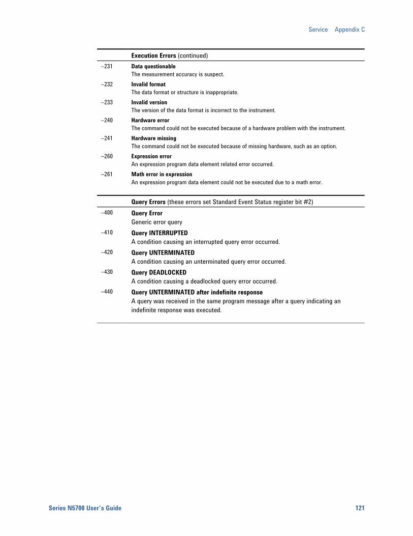
Service Appendix C
Series N5700 User’s Guide 121
Execution Errors (continued) −231 Data questionable
The measurement accuracy is suspect. −232 Invalid format
The data format or structure is inappropriate. −233 Invalid version
The version of the data format is incorrect to the instrument. −240 Hardware error
The command could not be executed because of a hardware problem with the instrument. −241 Hardware missing
The command could not be executed because of missing hardware, such as an option. −260 Expression error
An expression program data element related error occurred. −261 Math error in expression
An expression program data element could not be executed due to a math error.
Query Errors (these errors set Standard Event Status register bit #2) −400 Query Error
Generic error query −410 Query INTERRUPTED
A condition causing an interrupted query error occurred. −420 Query UNTERMINATED
A condition causing an unterminated query error occurred. −430 Query DEADLOCKED
A condition causing a deadlocked query error occurred. −440 Query UNTERMINATED after indefinite response
A query was received in the same program message after a query indicating an indefinite response was executed.

Series N5700 User’s Guide 123
Appendix D Compatibility Differences – In General ................................................................................124 Compatibility Command Summary ...............................................................125
The Agilent N5700 power supplies are programmatically compatible with the Agilent 603xA power supplies. This means that you can remotely program the Agilent N5700 power supplies using the same commands that are used to program the 603xA power supplies.
CAUTION Do not mix Compatibility with SCPI commands in the same program. This will result in unpredictable instrument behavior.
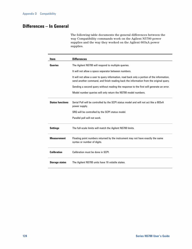
Appendix D Compatibility
124 Series N5700 User’s Guide
Differences – In General The following table documents the general differences between the way Compatibility commands work on the Agilent N5700 power supplies and the way they worked on the Agilent 603xA power supplies.
Item Differences
Queries The Agilent N5700 will respond to multiple queries.
It will not allow a space separator between numbers.
It will not allow a user to query information, read back only a portion of the information, send another command, and finish reading back the information from the original query.
Sending a second query without reading the response to the first will generate an error.
Model number queries will only return the N5700 model numbers.
Status functions Serial Poll will be controlled by the SCPI status model and will not act like a 603xA power supply.
SRQ will be controlled by the SCPI status model.
Parallel poll will not work.
Settings The full-scale limits will match the Agilent N5700 limits.
Measurement Floating point numbers returned by the instrument may not have exactly the same syntax or number of digits.
Calibration Calibration must be done in SCPI.
Storage states The Agilent N5700 units have 16 volatile states.
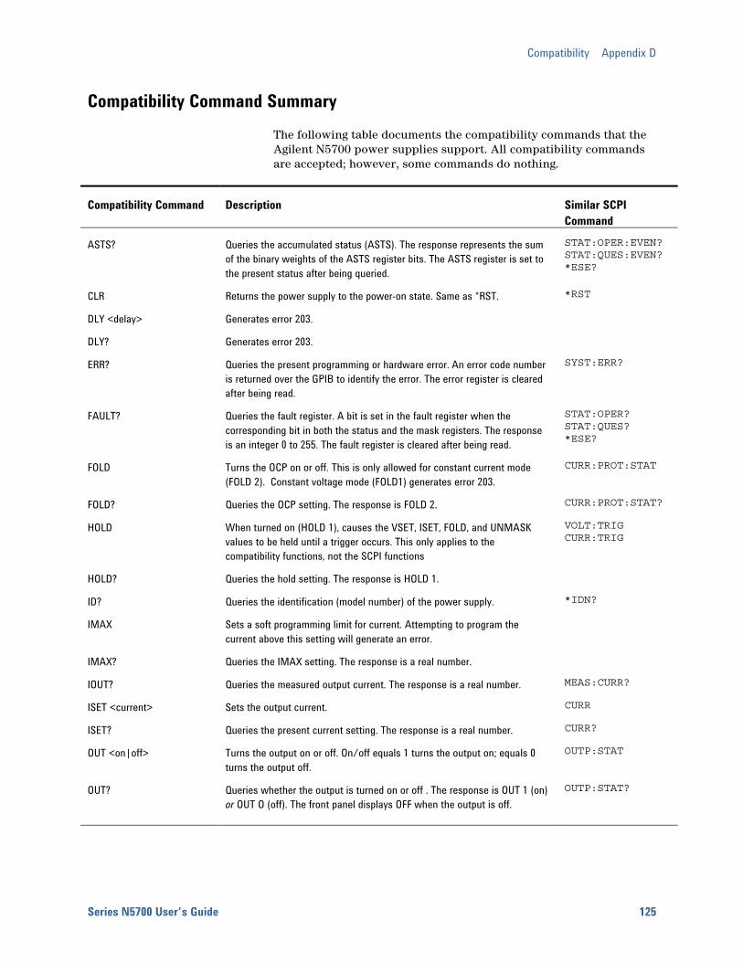
Compatibility Appendix D
Series N5700 User’s Guide 125
Compatibility Command Summary The following table documents the compatibility commands that the Agilent N5700 power supplies support. All compatibility commands are accepted; however, some commands do nothing.
Compatibility Command Description Similar SCPI Command
ASTS? Queries the accumulated status (ASTS). The response represents the sum of the binary weights of the ASTS register bits. The ASTS register is set to the present status after being queried.
STAT:OPER:EVEN? STAT:QUES:EVEN? *ESE?
CLR Returns the power supply to the power-on state. Same as *RST. *RST
DLY <delay> Generates error 203.
DLY? Generates error 203.
ERR? Queries the present programming or hardware error. An error code number is returned over the GPIB to identify the error. The error register is cleared after being read.
SYST:ERR?
FAULT? Queries the fault register. A bit is set in the fault register when the corresponding bit in both the status and the mask registers. The response is an integer 0 to 255. The fault register is cleared after being read.
STAT:OPER? STAT:QUES? *ESE?
FOLD Turns the OCP on or off. This is only allowed for constant current mode (FOLD 2). Constant voltage mode (FOLD1) generates error 203.
CURR:PROT:STAT
FOLD? Queries the OCP setting. The response is FOLD 2. CURR:PROT:STAT?
HOLD When turned on (HOLD 1), causes the VSET, ISET, FOLD, and UNMASK values to be held until a trigger occurs. This only applies to the compatibility functions, not the SCPI functions
VOLT:TRIG CURR:TRIG
HOLD? Queries the hold setting. The response is HOLD 1.
ID? Queries the identification (model number) of the power supply. *IDN?
IMAX Sets a soft programming limit for current. Attempting to program the current above this setting will generate an error.
IMAX? Queries the IMAX setting. The response is a real number.
IOUT? Queries the measured output current. The response is a real number. MEAS:CURR?
ISET <current> Sets the output current. CURR
ISET? Queries the present current setting. The response is a real number. CURR?
OUT <on|off> Turns the output on or off. On/off equals 1 turns the output on; equals 0 turns the output off.
OUTP:STAT
OUT? Queries whether the output is turned on or off . The response is OUT 1 (on) or OUT O (off). The front panel displays OFF when the output is off.
OUTP:STAT?

Appendix D Compatibility
126 Series N5700 User’s Guide
Compatibility Command Description Similar SCPI Command
OVP Sets the over-voltage trip point. VOLT:PROT:LEV
OVP? Queries the present over-voltage setting. The response is a real number. VOLT:PROT:LEV?
RCL <reg> Recalls the saved settings. There are up to 16 store/recall states. Saved settings must have been previously stored using the STO command.
*RCL
ROM? Queries the revision date of the power supply's firmware. *IDN?
RST Resets any tripped protection. OUTP:PROT:CLE
SRQ <setting> Generates error 203. The service request capability of the power supply is only supported using the SCPI commands
*SRQ
SRQ? Always returns 0. *SRQ?
STO <reg> Stores the present power supply settings in the specified register. There are up to 16 store/recall states.
*SAV
STS? Queries the present status. The response represents the sum of the binary weights of the status register bits. The response is STS <n>
STAT:OPER:COND? STAT:QUES:COND?
TEST? Always returns 0. *TST?
TRG Causes the settings held with HOLD 1 to be executed.
UNMASK <setting> Sets the bits in the mask register to the setting. The setting is an integer that represents the sum of the binary weights of the bits. The mask register operates in conjunction with the status and fault registers.
STAT:OPER:NTR STAT:OPER:PTR STAT:QUES:NTR STAT:QUES:PTR
UNMASK? Queries the present setting of the mask register. The response is UNMASK <n>.
STAT:OPER:NTR? STAT:OPER:PTR? STAT:QUES:NTR? STAT:QUES:PTR?
VMAX Sets the soft programming limit for voltage. Attempting to program the voltage above this setting will generate an error.
VMAX? Queries the VMAX setting. The response is VMAX <n>.
VOUT? Queries the measured output voltage. The response is a real number. MEAS:VOLT?
VSET <voltage> Sets the output voltage. VOLT
VSET? Queries the present voltage setting. The response is a real number.
VOLT?
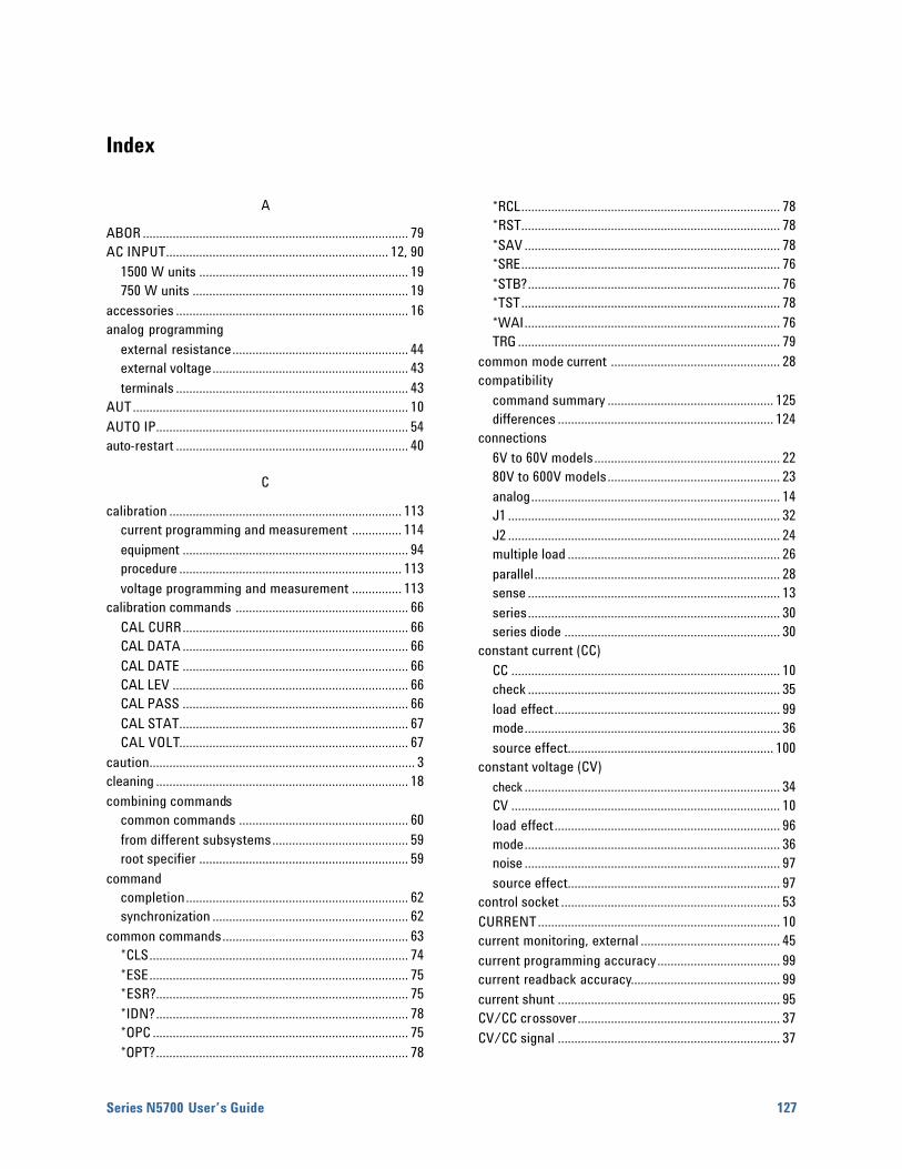
Series N5700 User’s Guide 127
Index
A
ABOR ................................................................................ 79 AC INPUT................................................................... 12, 90
1500 W units ............................................................... 19 750 W units ................................................................. 19
accessories ...................................................................... 16 analog programming
external resistance..................................................... 44 external voltage........................................................... 43 terminals ...................................................................... 43
AUT................................................................................... 10 AUTO IP............................................................................ 54 auto-restart ...................................................................... 40
C
calibration ...................................................................... 113 current programming and measurement ............... 114 equipment .................................................................... 94 procedure ................................................................... 113 voltage programming and measurement ............... 113
calibration commands .................................................... 66 CAL CURR.................................................................... 66 CAL DATA .................................................................... 66 CAL DATE .................................................................... 66 CAL LEV ....................................................................... 66 CAL PASS .................................................................... 66 CAL STAT..................................................................... 67 CAL VOLT..................................................................... 67
caution................................................................................ 3 cleaning ............................................................................ 18 combining commands
common commands ................................................... 60 from different subsystems......................................... 59 root specifier ............................................................... 59
command completion................................................................... 62 synchronization ........................................................... 62
common commands........................................................ 63 *CLS.............................................................................. 74 *ESE.............................................................................. 75 *ESR?............................................................................ 75 *IDN?............................................................................ 78 *OPC ............................................................................. 75 *OPT?............................................................................ 78
*RCL.............................................................................. 78 *RST.............................................................................. 78 *SAV ............................................................................. 78 *SRE.............................................................................. 76 *STB?............................................................................ 76 *TST.............................................................................. 78 *WAI............................................................................. 76 TRG ............................................................................... 79
common mode current ................................................... 28 compatibility
command summary .................................................. 125 differences ................................................................. 124
connections 6V to 60V models........................................................ 22 80V to 600V models.................................................... 23 analog........................................................................... 14 J1 .................................................................................. 32 J2 .................................................................................. 24 multiple load ................................................................ 26 parallel.......................................................................... 28 sense ............................................................................ 13 series............................................................................ 30 series diode ................................................................. 30
constant current (CC) CC ................................................................................. 10 check ............................................................................ 35 load effect.................................................................... 99 mode............................................................................. 36 source effect.............................................................. 100
constant voltage (CV) check ............................................................................. 34 CV ................................................................................. 10 load effect.................................................................... 96 mode............................................................................. 36 noise ............................................................................. 97 source effect................................................................ 97
control socket .................................................................. 53 CURRENT......................................................................... 10 current monitoring, external .......................................... 45 current programming accuracy..................................... 99 current readback accuracy............................................. 99 current shunt ................................................................... 95 CV/CC crossover............................................................. 37 CV/CC signal ................................................................... 37

Index
128 Series N5700 User’s Guide
D
daisy-chain shut down ................................................... 42 damage ............................................................................. 17 data socket....................................................................... 53 DC AMPS ......................................................................... 10 DC VOLTS ......................................................................... 10 Default Gateway.............................................................. 55 device clear ...................................................................... 62 DHCP ................................................................................ 54 DNS................................................................................... 55 Domain ............................................................................. 56
E
electronic load ................................................................. 95 enable/disable terminals ............................................... 41 environmental conditions ......................................... 17, 90 ERR.................................................................................... 76 error messages.............................................................. 118 ESB ................................................................................... 76
F
features .............................................................................. 8 FINE .................................................................................. 11 front panel locking .......................................................... 39 functions ............................................................................ 9
G
GPIB address ................................................................... 48 GPIB interface ................................................................. 48 grounding ................................................................... 17, 28
H
history.................................................................................. 2 Hostname......................................................................... 55
I
impedance effects........................................................... 27 inductive loads ................................................................ 27 initiate commands
INIT ............................................................................... 79 INIT CONT................................................................... 79
inspection......................................................................... 17 IO ...................................................................................... 48 IP Address........................................................................ 55 items supplied ................................................................. 16
J
J1 connector .................................................................... 12 J2 connector .................................................................... 12
K
Keepalive.......................................................................... 56 keywords .......................................................................... 59
L
LAN interface .................................................................. 49 setup utility.................................................................. 56 sockets......................................................................... 53 Telnet ........................................................................... 53
LAN, private ..................................................................... 51 LAN, site........................................................................... 50 last setting memory........................................................ 40 LFP .................................................................................... 11 LIMIT ................................................................................ 11 load wiring ....................................................................... 21 local voltage sensing...................................................... 25 lock front panel................................................................ 39
M
magnetic fields ................................................................ 17 master unit ....................................................................... 29 MAV.................................................................................. 76 measure commands........................................................ 67
MEAS CURR?............................................................... 67 MEAS VOLT?............................................................... 67
message terminator ........................................................ 60 end or identify ............................................................. 60 newline......................................................................... 60
model numbers................................................................ 16 model ratings ..................................................................... 9 MSS .................................................................................. 76 multiple load connections .............................................. 26 multipliers ........................................................................ 61
N
numerical data formats .................................................. 61
O
OCP ................................................................................... 11 OPER ................................................................................. 76 operating checklist........................................................ 116 optional commands......................................................... 58 OUP................................................................................... 11

Index
Series N5700 User’s Guide 129
OUT ON ............................................................................... 10 outline diagram.................................................................. 17 output commands ............................................................. 68
OUTP ............................................................................... 68 OUTP PON STAT........................................................... 68 OUTP PROT CLE............................................................ 68
output grounding ............................................................... 28 output noise ....................................................................... 27 output on/off control........................................................ 40 output programming example......................................... 82 over-current check ............................................................ 35 over-current protection ..............................................30, 38 over-temperature protection ........................................... 39 over-voltage check ............................................................ 34 over-voltage protection ..............................................30, 37 OVP ...................................................................................... 11
P
POWER................................................................................ 11 power cord, connecting.................................................... 19 power receptacle............................................................... 17 power supply OK signal.................................................... 42 power-fail protection ........................................................ 39 print date................................................................................. 2 PROT .................................................................................... 11 protection functions.......................................................... 37
Q
queries................................................................................. 60 QUES .................................................................................... 76
R
rack mounting .................................................................... 18 REM...................................................................................... 11 remote voltage sensing.................................................... 25 repackaging ...................................................................... 116 repacking............................................................................. 17 response data types.......................................................... 61 RQS ...................................................................................... 76
S
SAF....................................................................................... 10 safe-start............................................................................. 40 safety ...............................................................................3, 17 SCPI
command completion................................................... 62 command path............................................................... 58 commands...................................................................... 64
device clear ....................................................................62 message unit..................................................................59 multiple commands ......................................................58 syntax ..............................................................................58
shut off terminals ..............................................................40 slave unit .............................................................................29 sockets.................................................................................53 source commands .............................................................69
[SOUR] CURR [IMM].....................................................69 [SOUR] CURR PROT STAT...........................................69 [SOUR] CURR TRIG .......................................................69 [SOUR] VOLT [IMM] .....................................................69 [SOUR] VOLT LIM LOW ...............................................70 [SOUR] VOLT PROT LEV ..............................................70 [SOUR] VOLT TRIG........................................................69
specifications characteristics ...............................................................89 performance ...................................................................88
status commands ..............................................................71 STAT OPER COND?.......................................................72 STAT OPER ENAB.........................................................72 STAT OPER NTR............................................................73 STAT OPER PTR ............................................................73 STAT OPER?...................................................................72 STAT PRES .....................................................................72 STAT QUES COND? ......................................................73 STAT QUES ENAB ........................................................74 STAT QUES NTR............................................................74 STAT QUES PTR ............................................................74 STAT QUES?...................................................................73
Subnet Mask.......................................................................55 subsystem commands ......................................................63 suffixes ................................................................................61 support rails ........................................................................18 SW1 switch.................................................................. 12, 13 system commands.............................................................77
SYST COMM RLST........................................................77 SYST COMM TCP CONT ..............................................77 SYST ERR? ......................................................................77 SYST VERS?....................................................................77
T
Telnet ...................................................................................53 transient recovery time.....................................................98 trigger commands..............................................................79
TRIG .................................................................................79 TRIG SOUR .....................................................................79
trigger programming example .........................................84 turn-on check out ..............................................................34
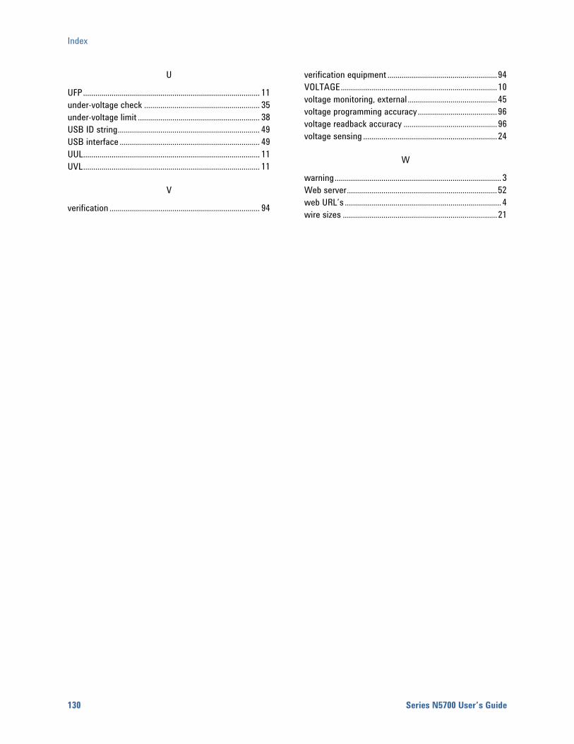
Index
130 Series N5700 User’s Guide
U
UFP....................................................................................... 11 under-voltage check ......................................................... 35 under-voltage limit ............................................................ 38 USB ID string...................................................................... 49 USB interface ..................................................................... 49 UUL....................................................................................... 11 UVL....................................................................................... 11
V
verification .......................................................................... 94
verification equipment ......................................................94 VOLTAGE.............................................................................10 voltage monitoring, external ............................................45 voltage programming accuracy.......................................96 voltage readback accuracy ..............................................96 voltage sensing ..................................................................24
W
warning.................................................................................. 3 Web server..........................................................................52 web URL’s ............................................................................. 4 wire sizes ............................................................................21
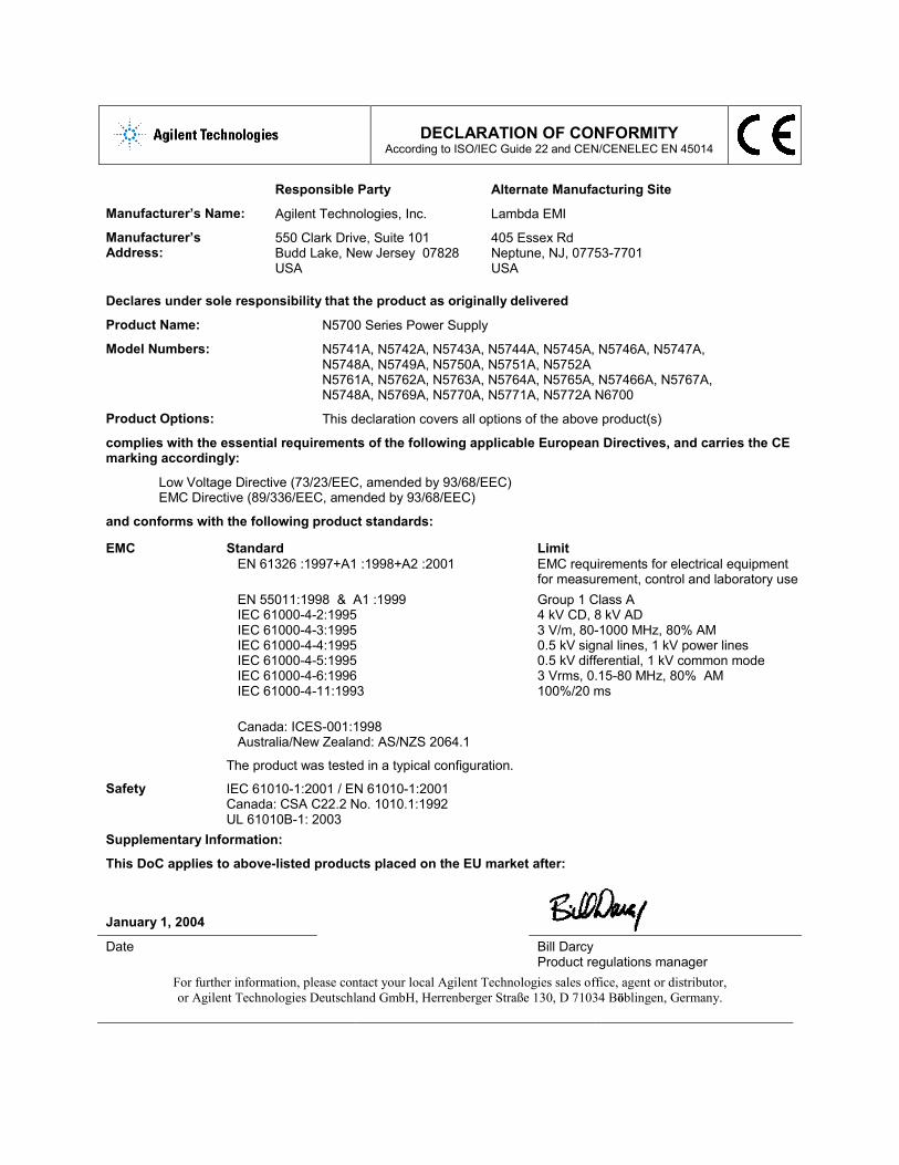
DECLARATION OF CONFORMITY
According to ISO/IEC Guide 22 and CEN/CENELEC EN 45014
Responsible Party Alternate Manufacturing Site
Manufacturer’s Name: Agilent Technologies, Inc. Lambda EMI
Manufacturer’s Address:
550 Clark Drive, Suite 101 Budd Lake, New Jersey 07828 USA
405 Essex Rd Neptune, NJ, 07753-7701 USA
Declares under sole responsibility that the product as originally delivered
Product Name: N5700 Series Power Supply
Model Numbers: N5741A, N5742A, N5743A, N5744A, N5745A, N5746A, N5747A, N5748A, N5749A, N5750A, N5751A, N5752A N5761A, N5762A, N5763A, N5764A, N5765A, N57466A, N5767A, N5748A, N5769A, N5770A, N5771A, N5772A N6700
Product Options: This declaration covers all options of the above product(s)
complies with the essential requirements of the following applicable European Directives, and carries the CE marking accordingly:
Low Voltage Directive (73/23/EEC, amended by 93/68/EEC) EMC Directive (89/336/EEC, amended by 93/68/EEC)
and conforms with the following product standards:
EMC Standard EN 61326 :1997+A1 :1998+A2 :2001 EN 55011:1998 & A1 :1999 IEC 61000-4-2:1995 IEC 61000-4-3:1995 IEC 61000-4-4:1995 IEC 61000-4-5:1995 IEC 61000-4-6:1996 IEC 61000-4-11:1993 Canada: ICES-001:1998 Australia/New Zealand: AS/NZS 2064.1
Limit EMC requirements for electrical equipment for measurement, control and laboratory use Group 1 Class A 4 kV CD, 8 kV AD 3 V/m, 80-1000 MHz, 80% AM 0.5 kV signal lines, 1 kV power lines 0.5 kV differential, 1 kV common mode 3 Vrms, 0.15-80 MHz, 80% AM 100%/20 ms
The product was tested in a typical configuration.
Safety IEC 61010-1:2001 / EN 61010-1:2001 Canada: CSA C22.2 No. 1010.1:1992 UL 61010B-1: 2003
Supplementary Information:
This DoC applies to above-listed products placed on the EU market after:
January 1, 2004
Date Bill Darcy
Product regulations manager For further information, please contact your local Agilent Technologies sales office, agent or distributor, or Agilent Technologies Deutschland GmbH, Herrenberger Straße 130, D 71034 Böblingen, Germany.