Agilent U1452A, U1452AT, and U1451A Manual · 2019. 6. 7. · Agilent Technologies Agilent U1452A,...
119
Agilent Technologies Agilent U1452A, U1452AT, and U1451A Insulation Tester User’s Guide Test Equipment Depot - 800.517.8431 - 99 Washington Street Melrose, MA 02176 - TestEquipmentDepot.com
Transcript of Agilent U1452A, U1452AT, and U1451A Manual · 2019. 6. 7. · Agilent Technologies Agilent U1452A,...
Test Equipment Depot - 800.517.8431 - 99 Washington Street Melrose, MA 02176 - TestEquipmentDepot.com
Agilent U1452A, U1452AT, and U1451A Insulation Tester
User’s Guide
Agilent Technologies

II U1452A/U1452AT/U1451A User’s Guide
Notices© Agilent Technologies, Inc. 2014
No part of this manual may be reproduced in any form or by any means (including elec-tronic storage and retrieval or translation into a foreign language) without prior agree-ment and written consent from Agilent Technologies, Inc. as governed by United States and international copyright laws.
Manual Part NumberU1451-90003
EditionFirst Edition, January 13, 2014
Agilent Technologies, Inc. 5301 Stevens Creek Blvd. Santa Clara, CA 95051 USA
WarrantyThe material contained in this docu-ment is provided “as is,” and is sub-ject to being changed, without notice, in future editions. Further, to the max-imum extent permitted by applicable law, Agilent disclaims all warranties, either express or implied, with regard to this manual and any information contained herein, including but not limited to the implied warranties of merchantability and fitness for a par-ticular purpose. Agilent shall not be liable for errors or for incidental or consequential damages in connec-tion with the furnishing, use, or per-formance of this document or of any information contained herein. Should Agilent and the user have a separate written agreement with warranty terms covering the material in this document that conflict with these terms, the warranty terms in the sep-arate agreement shall control.
Technology Licenses The hardware and or software described in this document are furnished under a license and may be used or copied only in accor-dance with the terms of such license.
Restricted Rights LegendU.S. Government Restricted Rights. Soft-ware and technical data rights granted to the federal government include only those rights customarily provided to end user cus-tomers. Agilent provides this customary commercial license in Software and techni-cal data pursuant to FAR 12.211 (Technical Data) and 12.212 (Computer Software) and, for the Department of Defense, DFARS 252.227-7015 (Technical Data - Commercial Items) and DFARS 227.7202-3 (Rights in Commercial Computer Software or Com-puter Software Documentation).
Safety Notices
CAUTION
A CAUTION notice denotes a haz-ard. It calls attention to an operat-ing procedure, practice, or the like that, if not correctly performed or adhered to, could result in damage to the product or loss of important data. Do not proceed beyond a CAUTION notice until the indicated conditions are fully understood and met.
WARNING
A WARNING notice denotes a hazard. It calls attention to an operating procedure, practice, or the like that, if not correctly per-formed or adhered to, could result in personal injury or death. Do not proceed beyond a WARNING notice until the indicated condi-tions are fully understood and met.

Safety Symbols
The following symbols on the instrument and in the documentation indicate precautions which must be taken to maintain safe operation of the instrument.
Direct current (DC) Caution, risk of electric shock
Alternating current (AC)Caution, risk of danger (refer to this manual for specific Warning or Caution information)
Both direct and alternating current
Category III 1000 V overvoltage protection
Earth (ground) terminalCategory IV 600 V overvoltage protection
Equipment protected throughout by double insulation or reinforcedinsulation
Do not use in distribution systems with voltages higher than 600 V
CAT III1000 V
CAT IV600 V
U1452A/U1452AT/U1451A User’s Guide III
Safety Considerations
Read the information below before using this tester. Model U1452A appears in all illustrations.
WARNING • Do not use the tester if it is damaged. Before you use the tester, inspect the case. Look for cracks or missing plastic. Pay particular attention to the insulation surrounding the connectors.
• Inspect the test leads for damaged insulation or exposed metal. Check the test leads for continuity. Replace damaged test leads before you use the tester.
• Do not operate the tester around explosive gas, vapor, or wet environments.
• Do not apply more than the rated voltage (as marked on the tester) between terminals, or between terminal and earth ground.
• Before use, verify the tester's operation by measuring a known voltage.
• When servicing the tester, use only the specified replacement parts.
• Use caution when working above 60 VDC, 30 VAC RMS, or 42.4 V peak. Such voltages pose a shock hazard.
• When using the probes, keep your fingers behind the finger guards on the probes.
• Connect the common test lead before you connect the live test lead. When you disconnect the leads, disconnect the live test lead first.
• Remove the test leads from the tester before you open the battery cover.
• Do not operate the tester with the battery cover or portions of the cover removed or loosened.
• To avoid false readings, which may lead to possible electric shock or personal injury, replace the battery as soon as the low battery indicator appears and flashes.
• Ensure that you do not perform insulation resistance tests in distribution systems with voltages higher than 600 V.
• For insulation resistance tests, ensure that you select a suitable test voltage for the equipment to be tested.
IV U1452A/U1452AT/U1451A User’s Guide

CAUTION • Disconnect circuit power and discharge all high-voltage capacitors before testing resistance, continuity, or capacitance.
• Use the proper terminals, function, and range for your measurements.
• This device is for use at altitudes of up to 2,000 m.
• Always use the specified battery type. The power for the tester is supplied with four 1.5 V AA batteries. Observe the correct polarity markings before you insert the batteries to ensure proper insertion of the batteries in the tester.
U1452A/U1452AT/U1451A User’s Guide V
Environmental Conditions
This instrument is designed for indoor use and in an area with low condensation. The table below shows the general environmental requirements for this instrument.
Environmental condition Requirement
Temperature
• Operating condition• –20 °C to 55 °C, 0% to 80% RH (using Alkaline batteries),
20 minutes operating time• Storage condition
• –40 °C to 70 °C, 0% to 80% RH (without batteries)
HumidityFull accuracy up to 80% RH for temperatures up to 30 °C, decreasing linearly to 50% RH at 55 °C
Altitude Up to 2,000 meters
Pollution degree Pollution degree II
NOTEThe U1452A/U1452AT/U1451A Insulation Tester complies with the following safety and EMC requirements:• Safety compliance
• Designed in compliance to IEC/EN 61010-1:2010 for Category III 1000 V and Category IV 600 V• Designed in compliance to IEC/EN 61557-1, IEC/EN 61557-2, and IEC/EN 61557-4
• EMC compliance• Commercial limits compliance with IEC 61326-1:2005/EN 61326-1:2006
VI U1452A/U1452AT/U1451A User’s Guide

Regulatory Markings
The CE mark is a registered trademarkof the European Community. This CEmark shows that the product complieswith all the relevant European LegalDirectives.
The C-tick mark is a registered trademark of the Spectrum Management Agency of Australia. This signifies compliance withthe Australia EMC Frameworkregulations under the terms of the Radio Communication Act of 1992.
ICES/NMB-001 indicates that this ISM device complies with the Canadian ICES-001.Cet appareil ISM est confomre a la norme NMB-001 du Canada.
This instrument complies with the WEEE Directive (2002/96/EC) marking requirement. This affixed product label indicates that you must not discard this electrical or electronic product in domestic household waste.
The CSA mark is a registered trademark of the Canadian Standards Association.
This symbol indicates the time period during which no hazardous or toxic substance elements are expected to leak or deteriorate during normal use. Forty years is the expected useful life of the product.
U1452A/U1452AT/U1451A User’s Guide VII

Waste Electrical and Electronic Equipment (WEEE) Directive 2002/96/EC
This instrument complies with the WEEE Directive (2002/96/EC) marking requirement. This affixed product label indicates that you must not discard this electrical or electronic product in domestic household waste.
Product Category:
With reference to the equipment types in the WEEE directive Annex 1, this instrument is classified as a “Monitoring and Control Instrument” product.
The affixed product label is as shown below.
Do not dispose in domestic household waste.
VIII U1452A/U1452AT/U1451A User’s Guide
Declaration of Conformity (DoC)
The Declaration of Conformity (DoC) for this instrument is available on the Agilent website. You can search the DoC by its product model or description at:
http://regulations.corporate.agilent.com/DoC/search.htm
NOTE If you are unable to search for the respective DoC, please contact your local Agilent representative.
U1452A/U1452AT/U1451A User’s Guide IX

THIS PAGE HAS BEEN INTENTIONALLY LEFT BLANK.
X U1452A/U1452AT/U1451A User’s Guide
Table of Contents
1 Introduction
About This Manual 2
Documentation map 2Safety notes 2
Preparing Your Tester 3
Check the shipment 3Install or change the batteries 3Turn on your tester 6Select the range 6Adjust the tilt stand 7Connect to the Handheld Meter Logger Software 8Connect the Bluetooth adapter 9
Your Tester in Brief 10
Dimensions 10Overview 12Rotary switch 14Keypad 16Display screen 20Input terminals 24
Cleaning Your Tester 25
Additional Features 26
Automatic power-off 26Hazardous voltage indication 26Power-on options 26
2 Making Measurements
Insulation Resistance Test 30
Using the Remote Switch Probe 32
U1452A/U1452AT/U1451A User’s Guide XI

Locking the test 33Timed insulation resistance/earth-bond resistance test 34Measuring the Dielectric Absorption Ratio (DAR) 35Measuring the Polarization Index (PI) 36Viewing the leakage current 37
Earth-Bond Resistance Test 38
Measuring AC or DC Voltage 41
Auto AC or DC signal identification 43
Measuring Frequency 44
Measuring Resistance 46
Continuity Test 48
Measuring Capacitance 50
3 Tester Features
Making Relative Measurements (Null) 54
Freezing the Display (TrigHold and AutoHold) 55
Performing Limit Comparisons (Limit) 57
Recording Measurement Data (Log) 59
Performing manual logs (HAND) 60Performing interval logs (AUTO) 60Performing event logs (TRIG) 61
Reviewing Previously Recorded Data (View) 63
4 Setup Options
Using the Setup Menu 66
Editing numerical values 67
Setup Menu Summary 68
Setup Menu Items 71
XII U1452A/U1452AT/U1451A User’s Guide
Changing the variation count 71Enabling smooth mode 71Changing the beep frequency 72Changing the auto power-off (APO) timer 73Changing the LCD backlight timeout 73Changing the continuity alert 74Disabling the power-on melody 75Changing the battery type 75Resetting the tester’s Setup options 76Changing the display count 76Changing the cable length unit 77Changing the cable length scale 78Changing the alert indicators 78Changing the sample interval duration 79Changing the recording option 80Changing the IR and EBR test period 80Changing the maximum inhibit voltage for IR tests 81Disabling the lock once feature 82Changing the button operation on the remote switch probe 82Changing the Dielectric Absorption Ratio (DAR) for IR
tests 83
5 Characteristics and Specifications
Product Characteristics 86
Specification Considerations 88
Measurement Category 88
Electrical Specifications 89
DC specifications 89AC specifications 91Capacitance specifications 92Frequency specifications 93Sensitivity for voltage measurements 94
U1452A/U1452AT/U1451A User’s Guide XIII

Insulation resistance specifications 95Earth-bond resistance specifications 97EN61557 specifications 97Display update rate (approximate) 99
XIV U1452A/U1452AT/U1451A User’s Guide
List of Figures
Figure 1-1 Agilent Handheld Meter Logger Software 8Figure 1-2 Bluetooth adapter connection 9Figure 1-3 Width dimension 10Figure 1-4 Height and depth dimensions 11Figure 1-5 Display screen allocation example 20Figure 1-6 Connecting the remote switch probe 24Figure 2-1 Insulation resistance test example 31Figure 2-2 T/Time operation 34Figure 2-3 DAR operation 35Figure 2-4 PI operation 36Figure 2-5 Earth-bond resistance test example 39Figure 2-6 AC or DC voltage measurement example 42Figure 2-7 Definition of frequency 45Figure 2-8 Resistance measurement example 47Figure 2-9 Continuity test example 49Figure 2-10 Capacitance measurement example 51
U1452A/U1452AT/U1451A User’s Guide XV

THIS PAGE HAS BEEN INTENTIONALLY LEFT BLANK.
XVI U1452A/U1452AT/U1451A User’s Guide
List of Tables
Table 1-1 Front panel part descriptions 12Table 1-2 Rear panel parts 13Table 1-3 U1452A/U1452AT/U1451A rotary switch functions 14Table 1-4 U1452A/U1452AT/U1451A keypad functions 16Table 1-5 General annunciators 20Table 1-6 Measurement units display 22Table 1-7 Analog bar graph display 23Table 1-8 Terminal connections for different measuring
functions 24Table 1-9 Power-on options 26Table 2-1 Rotary switch position for insulation resistance
tests 30Table 2-2 Earth-bond resistance test position 38Table 2-3 AC and DC voltage measurement positions 41Table 2-4 Resistance measurement position 46Table 2-5 Continuity test position 48Table 2-6 Capacitance measurement position 50Table 3-1 Limit settling default values 57Table 3-2 Log maximum capacity 59Table 3-3 Event log trigger conditions 61Table 4-1 Setup menu key functions 66Table 4-2 Setup menu item descriptions 68Table 5-1 DC voltage specifications with accuracy of ± (% of
reading + no. of least significant digit) 89Table 5-2 Resistance specifications with accuracy of ± (% of
reading + no. of least significant digit) 90Table 5-3 AC voltage specifications with accuracy of ± (% of
reading + no. of least significant digit) 91Table 5-4 Capacitance specifications with accuracy of ± (% of
reading + no. of least significant digit)[1][2][3] 92Table 5-5 Frequency specifications with accuracy of ± (% of
reading + no. of least significant digit)[1][2] 93Table 5-6 Sensitivity for voltage measurements 94Table 5-7 Insulation resistance specifications with accuracy of ±
(% of reading + no. of least significant digit) 95
U1452A/U1452AT/U1451A User’s Guide XVII

Table 5-8 Earth-bond resistance specifications with accuracy of ± (% of reading + no. of least significant digit)[1][2] 97
Table 5-9 Display update rate (approximate) 99
XVIII U1452A/U1452AT/U1451A User’s Guide
U1452A/U1452AT/U1451A Insulation TesterUser’s Guide
1Introduction
About This Manual 2Documentation map 2Safety notes 2
Preparing Your Tester 3Check the shipment 3Install or change the batteries 3Turn on your tester 6Select the range 6Adjust the tilt stand 7Connect to the Handheld Meter Logger Software 8Connect the Bluetooth adapter 9
Your Tester in Brief 10Dimensions 10Overview 12Rotary switch 14Keypad 16Display screen 20Input terminals 24
Cleaning Your Tester 25
Additional Features 26Automatic power-off 26Hazardous voltage indication 26Power-on options 26
This chapter teaches you how to set up your tester for the first time. An introduction to all the features of the tester is also given.
1Agilent Technologies
1 IntroductionAbout This Manual
About This Manual
Safety notes
The following safety notes are used throughout this manual. More pertinent safety notes for using this product are located under the “Safety Symbols” section.
CAUTION Caution denotes a hazard. It calls attention to a procedure that, if not correctly performed or adhered to, could result in damage to or destruction of the product. Do not proceed beyond a caution notice until the indicated conditions are fully understood and met.
WARNING Warning denotes a hazard. It calls attention to a procedure which, if not correctlyperformed or adhered to, could result in injury or loss of life. Do not proceed beyond a warning note until the indicated conditions are fully understood and met.
2 U1452A/U1452AT/U1451A User’s Guide
Introduction 1 Preparing Your Tester
Preparing Your Tester
Check the shipment
When you receive your tester, check the shipment according to the following procedure.
1 Inspect the shipping container for damage. Signs of damage may include a dented or torn shipping container or cushioning material that indicates signs of unusual stress or compacting. Save the packaging material in case the tester needs to be returned.
2 Carefully remove the contents from the shipping container, and verify that the standard accessories and your ordered options are included in the shipment according to the standard shipped items list found in the printed copy of the U1452A/U1452AT/U1451A Quick Start Guide.
3 For any question or problems, refer to the Agilent contact numbers on the back of this manual.
Install or change the batteries
Your tester is powered by four 1.5 V AA alkaline batteries (included in the shipment). When you receive your tester, the batteries are not installed.
Use the following procedure to install or change the batteries.
CAUTION Before you proceed with the batteries installation, remove all cable connections to the terminals and ensure that the rotary switch is at the position. Use only the battery type specified in the “Product Characteristics” on page 86.
U1452A/U1452AT/U1451A User’s Guide 3

1 Introduction Preparing Your Tester
1 Remove the orange rubber holster. Pull from a top corner and stretch the orange rubber holster off the tester.
2 Loosen and remove the two screws with a suitable Phillips screwdriver as shown on the right.
3 Lift up and remove the battery cover as shown on the left.
4 Lift the inner rubber cover to access the battery compartment.
5 Observe the proper batteries polarity. The terminal ends of each battery are indicated inside the battery compartment. Insert four 1.5 V AA batteries.
6 Ensure that the inner rubber cover is positioned properly.
7 Replace the battery cover back in its original position and tighten the screws.
8 Finally fit the orange rubber holster back on the tester.
4 U1452A/U1452AT/U1451A User’s Guide
Introduction 1 Preparing Your Tester
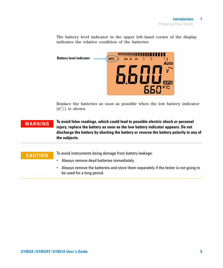
The battery level indicator in the upper left- hand corner of the display indicates the relative condition of the batteries.
Replace the batteries as soon as possible when the low battery indicator ( ) is shown.
Battery level indicator
WARNING To avoid false readings, which could lead to possible electric shock or personal injury, replace the battery as soon as the low battery indicator appears. Do not discharge the battery by shorting the battery or reverse the battery polarity in any of the subjects.
CAUTION To avoid instruments being damage from battery leakage:
• Always remove dead batteries immediately.
• Always remove the batteries and store them separately if the tester is not going to be used for a long period.
U1452A/U1452AT/U1451A User’s Guide 5

1 Introduction Preparing Your Tester
Turn on your tester
To power ON your tester, turn the rotary switch from the position to any other position.
Select the range
The tester’s selected range is always displayed on the right- hand end of the bar graph.
Selected range Autoranging indicator
6 U1452A/U1452AT/U1451A User’s Guide
Introduction 1 Preparing Your Tester
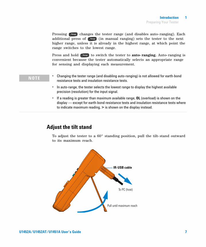
Pressing changes the tester range (and disables auto- ranging). Each additional press of (in manual ranging) sets the tester to the next higher range, unless it is already in the highest range, at which point the range switches to the lowest range.
Press and hold to switch the tester to auto- ranging. Auto- ranging is convenient because the tester automatically selects an appropriate range for sensing and displaying each measurement.
Adjust the tilt stand
To adjust the tester to a 60° standing position, pull the tilt- stand outward to its maximum reach.
NOTE • Changing the tester range (and disabling auto-ranging) is not allowed for earth-bond resistance tests and insulation resistance tests.
• In auto-range, the tester selects the lowest range to display the highest available precision (resolution) for the input signal.
• If a reading is greater than maximum available range, OL (overload) is shown on the display — except for earth-bond resistance tests and insulation resistance tests where to indicate maximum reading, > is shown on the display instead.
To PC (host)
IR-USB cable
Pull until maximum reach
U1452A/U1452AT/U1451A User’s Guide 7
1 IntroductionPreparing Your Tester
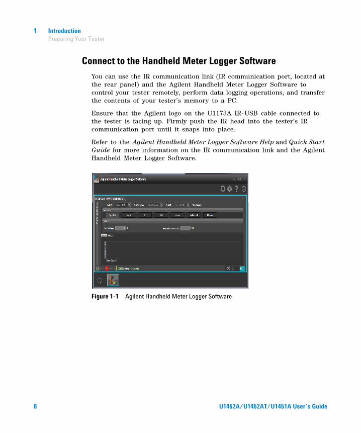
Connect to the Handheld Meter Logger Software
You can use the IR communication link (IR communication port, located at the rear panel) and the Agilent Handheld Meter Logger Software to control your tester remotely, perform data logging operations, and transfer the contents of your tester’s memory to a PC.
Ensure that the Agilent logo on the U1173A IR- USB cable connected to the tester is facing up. Firmly push the IR head into the tester’s IR communication port until it snaps into place.
Refer to the Agilent Handheld Meter Logger Software Help and Quick Start Guide for more information on the IR communication link and the Agilent Handheld Meter Logger Software.
Figure 1-1 Agilent Handheld Meter Logger Software
8 U1452A/U1452AT/U1451A User’s Guide

Introduction 1 Preparing Your Tester
Connect the Bluetooth adapter
The U1117A Infrared (IR)- to- Bluetooth® adapter allows you to connect the tester wirelessly to any Windows PC, Android device, or iOS device.
The U1117A is compatible with the following application or software:
• Agilent Handheld Meter Logger (for Windows PC)
• Agilent Mobile Meter (for Android or iOS devices)
• Agilent Mobile Logger (for Android or iOS devices)
Snap the optic side of the U1117A to the tester’s IR communication port (see Figure 1- 2).
Figure 1-2 Bluetooth adapter connection
Bluetooth adapter
U1452A/U1452AT/U1451A User’s Guide 9
1 Introduction Your Tester in Brief
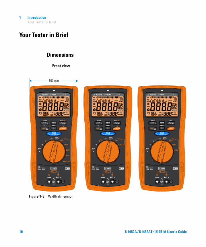
Your Tester in Brief
Dimensions
Front view
Figure 1-3 Width dimension
100 mm
10 U1452A/U1452AT/U1451A User’s Guide
Introduction 1 Your Tester in Brief
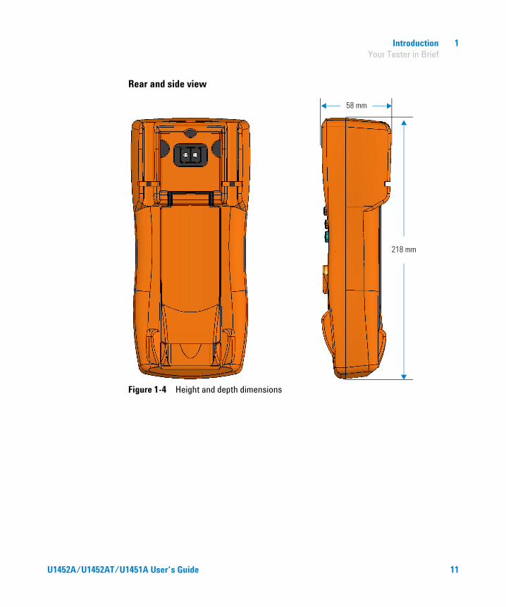
Rear and side view
Figure 1-4 Height and depth dimensions
218 mm
58 mm
U1452A/U1452AT/U1451A User’s Guide 11

1 Introduction Your Tester in Brief
Overview
Front panel
The front panel parts of your tester are described in this section.
Table 1-1 Front panel part descriptions
Legend Description Learn more on:
1 Red LED indicator page 54
2 Display screen page 20
3 Keypad page 16
4 Rotary switch page 14
5 Input terminals page 24
2
1
3
4
5
12 U1452A/U1452AT/U1451A User’s Guide
Introduction 1 Your Tester in Brief
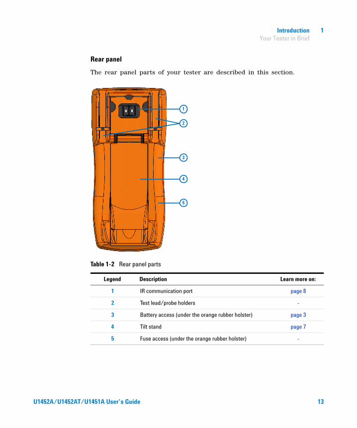
Rear panel
The rear panel parts of your tester are described in this section.
Table 1-2 Rear panel parts
Legend Description Learn more on:
1 IR communication port page 8
2 Test lead/probe holders -
3 Battery access (under the orange rubber holster) page 3
4 Tilt stand page 7
5 Fuse access (under the orange rubber holster) -
1
2
3
4
5
U1452A/U1452AT/U1451A User’s Guide 13
1 Introduction Your Tester in Brief
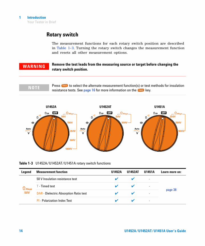
Rotary switch
The measurement functions for each rotary switch position are described in Table 1- 3. Turning the rotary switch changes the measurement function and resets all other measurement options.
WARNING Remove the test leads from the measuring source or target before changing the rotary switch position.
NOTE Press to select the alternate measurement function(s) or test methods for insulation resistance tests. See page 16 for more information on the key.
U1452A U1452AT U1451A
Table 1-3 U1452A/U1452AT/U1451A rotary switch functions
Legend Measurement function U1452A U1452AT U1451A Learn more on:
50 V Insulation resistance test ✔ ✔ -
page 38T - Timed test ✔ ✔ -
DAR - Dielectric Absorption Ratio test ✔ ✔ -
PI - Polarization Index Test ✔ ✔ -
14 U1452A/U1452AT/U1451A User’s Guide
Introduction 1 Your Tester in Brief
100 V Insulation resistance test ✔ ✔ -
page 38T - Timed test ✔ ✔ -
DAR - Dielectric Absorption Ratio test ✔ ✔ -
PI - Polarization Index Test ✔ ✔ -
250 V Insulation resistance test ✔ - ✔
page 38T - Timed test ✔ - ✔
DAR - Dielectric Absorption Ratio test ✔ - -
PI - Polarization Index Test ✔ - -
500 V Insulation resistance test ✔ - ✔
page 38T - Timed test ✔ - ✔
DAR - Dielectric Absorption Ratio test ✔ - -
PI - Polarization Index Test ✔ - -
1000 V Insulation resistance test ✔ - ✔
page 38T - Timed test ✔ - ✔
DAR - Dielectric Absorption Ratio test ✔ - -
PI - Polarization Index Test ✔ - -
Earth-bond resistance test ✔ ✔ ✔page 38
T - Timed test ✔ ✔ ✔
Resistance measurement ✔ ✔ ✔ page 46
Continuity test ✔ ✔ ✔ page 48
Capacitance measurement ✔ ✔ ✔ page 50
Auto voltage measurement ✔ ✔ ✔
page 30DC voltage measurement ✔ ✔ ✔
AC voltage measurement ✔ ✔ ✔
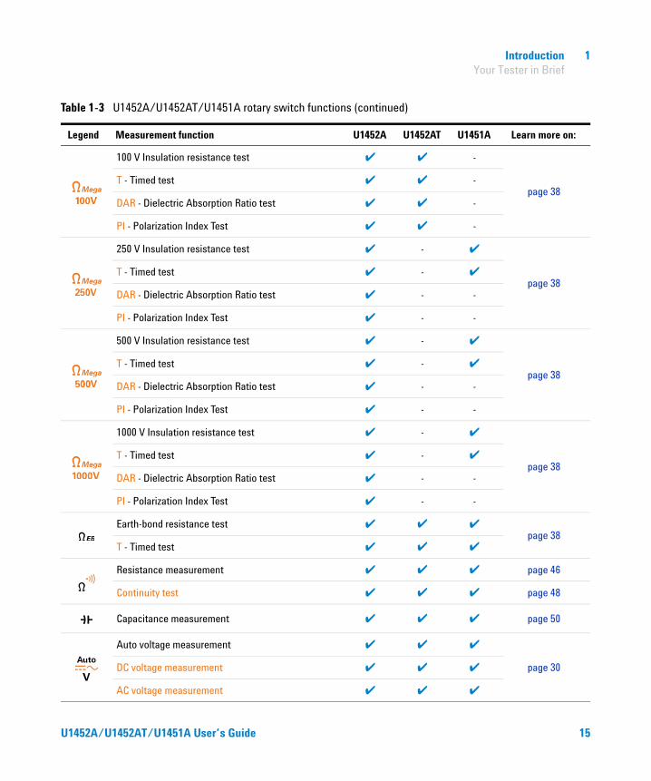
Table 1-3 U1452A/U1452AT/U1451A rotary switch functions (continued)
Legend Measurement function U1452A U1452AT U1451A Learn more on:
U1452A/U1452AT/U1451A User’s Guide 15
1 Introduction Your Tester in Brief
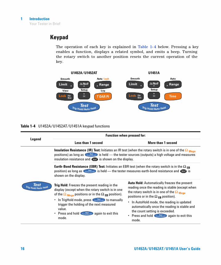
Keypad
The operation of each key is explained in Table 1- 4 below. Pressing a key enables a function, displays a related symbol, and emits a beep. Turning the rotary switch to another position resets the current operation of the key.
U1452A/U1452AT U1451A
Table 1-4 U1452A/U1452AT/U1451A keypad functions
LegendFunction when pressed for:
Less than 1 second More than 1 second
Insulation Resistance (IR) Test: Initiates an IR test (when the rotary switch is in one of the Ω Mega positions) as long as is held — the tester sources (outputs) a high voltage and measures insulation resistance and is shown on the display.
Earth-Bond Resistance (EBR) Test: Initiates an EBR test (when the rotary switch is in the Ω EB position) as long as is held — the tester measures earth-bond resistance and is shown on the display.
Trig Hold: Freezes the present reading in the display (except when the rotary switch is in one of the Ω Mega positions or in the Ω EB position).
• In TrigHold mode, press to manually trigger the holding of the next measured value.
• Press and hold again to exit this mode.
Auto Hold: Automatically freezes the present reading once the reading is stable (except when the rotary switch is in one of the Ω Mega positions or in the Ω EB position).
• In AutoHold mode, the reading is updated automatically once the reading is stable and the count setting is exceeded.
• Press and hold again to exit this mode.
16 U1452A/U1452AT/U1451A User’s Guide

Introduction 1 Your Tester in Brief
Lock: Press to lock the insulation test or earth-bond resistance test (when the rotary switch is in the appropriate position).
Press > to initiate an IR or EBR test. The test will remain active until you press
or again to release the lock.
View: Press and hold to enter the Log Review menu.
• Press to cycle through the previously recorded manual (VIEW H), interval (VIEW A), or event (VIEW E) logging data.
• Press or to view first or last logged data respectively.
• Press or to scroll through the logged data.
• Press to delete the last logged data.• Press and hold to clear all the logged
data for the selected logging mode.• Press and hold again to exit this mode.
Hz: Press to display the frequency for voltage or current measurements.
Press again to disable the frequency display.
Esc: Press in the Setup menu to discard your changes.
Press to switch or cycle between the default and alternate measurement function(s).
Log: The recording option (HAND, AUTO, or TRIG) must first be selected in the Setup menu (see page 80).
• HAND (manual data logging) — Press and hold to log the present reading into the memory. The display will return to normal after a short while (≈ 1 second). To manually log another reading, press and hold again.
• AUTO (automatic data logging) — Press and hold to enable the automatic data logging mode, where data is logged at the interval defined in the Setup menu (see page 79). Press and hold again to exit this mode.
• TRIG (event data logging) — Press and hold to enable the event data logging mode,
where data is logged each time a triggering condition is satisfied (see page 62). Press and hold again to exit this mode.
T: Configures the tester for a timed test (when the rotary switch is in one of the Ω Mega positions or the Ω EB position).
The test will start when you press .
DAR: Configures the tester for a dielectric absorption ratio test (when the rotary switch is in one of the Ω Mega positions).
The test will start when you press .
PI: Configures the tester for a polarization index test (when the rotary switch is in one of the Ω Mega positions).
The test will start when you press .
Table 1-4 U1452A/U1452AT/U1451A keypad functions (continued)
LegendFunction when pressed for:
Less than 1 second More than 1 second
U1452A/U1452AT
U1451A
U1452A/U1452AT
U1451A
U1452A/U1452AT/U1451A User’s Guide 17

1 Introduction Your Tester in Brief
Limit: Press to enable the comparison for limit mode.
• Press again to set the comparison value. Use the arrow keys to change the value shown and press to save your changes.
• Press and hold to exit this mode.
Smooth: Press and hold to smoothen the refresh rate of the readings.
Press and hold again to exit this mode.
Range: Press to set a manual range and disable auto-ranging.
Press again to cycle through each available measurement range.
Auto: Press and hold to enable auto-ranging.
Leak: Press to display the leakage current.
Null: Press to enable the relative function.
• The displayed value is saved as a reference to be subtracted from subsequent measurements.
• Press again to view the stored reference value that has been saved. The display will return to normal after a brief period of time (approx. 3 seconds).
• Pressing while the stored reference value is being displayed will cancel the relative function.
-
Table 1-4 U1452A/U1452AT/U1451A keypad functions (continued)
LegendFunction when pressed for:
Less than 1 second More than 1 second
U1452A/U1452AT
U1451A
18 U1452A/U1452AT/U1451A User’s Guide

Introduction 1 Your Tester in Brief
: Press to enable or disable the LCD backlight.
Setup: Press and hold to enter the Setup menu.
• In the Setup menu, press or to navigate through the menu pages. Press or at each menu page to move the cursor to a specific menu item.
• Press to change the value of the selected menu item. Use the arrow keys to change the value shown.
• Press again to save your changes, or press to discard your changes.
• Press and hold again to exit the Setup menu.
Table 1-4 U1452A/U1452AT/U1451A keypad functions (continued)
LegendFunction when pressed for:
Less than 1 second More than 1 second
U1452A/U1452AT/U1451A User’s Guide 19

1 Introduction Your Tester in Brief
Display screen
The display annunciators of your tester are described in this section. See also “Measurement units” on page 22 for a list of available measurement signs and notations and “Analog bar graph” on page 23 for a tutorial on the analog bar graph located at the bottom of your display screen.
Display annunciators
The display annunciators of your tester are described in the Table 1- 5.
Figure 1-5 Display screen allocation example
Table 1-5 General annunciators
Legend Description
Remote control enabled
Battery capacity indication
Analog bar graph
Test indication for insulation resistance and earth-bond resistance tests
Hazardous voltage sign for measuring voltage ≥30 V or OL (overload)
20 U1452A/U1452AT/U1451A User’s Guide

Introduction 1 Your Tester in Brief
Auto hold/Trigger hold enabled
Polarization Index test enabled
Dielectric Absorption Ratio test enabled
Timed test enabled
Relative (Null) enabled
Smooth mode enabled
Auto-ranging enabled or Auto signal indicator enabled
Greater than range (for insulation resistance and earth-bond resistance tests)
Test and Test Lock indication for insulation resistance and earth-bond resistance tests
Primary display
AC or DC indication
Measuring units for primary display
Test time indication for earth-bond resistance and insulation resistance tests
APO (Auto Power-Off) enabled
Limit comparison enabled
Data logging in progress
Table 1-5 General annunciators (continued)
Legend Description
U1452A/U1452AT/U1451A User’s Guide 21

1 Introduction Your Tester in Brief
Measurement units
The available signs and notations for each measurement function in your tester are described in Table 1- 6. The units listed below are applicable to the primary display and secondary display measurements of your tester.
View mode for reviewing previously logged data
Audible continuity test selected
Secondary display
Measuring units and AC+DC indication for secondary display
Tertiary display
Measuring units for tertiary display
Table 1-6 Measurement units display
Sign/Notation Description
G Giga 1E+09 (1000000000)
M Mega 1E+06 (1000000)
k kilo 1E+03 (1000)
n nano 1E–09 (0.000000001)
μ micro 1E–06 (0.000001)
m milli 1E–03 (0.001)
mV, V Voltage, units for voltage measurement
nF, μF, mF Farad, units for capacitance measurement
Table 1-5 General annunciators (continued)
Legend Description
22 U1452A/U1452AT/U1451A User’s Guide
Introduction 1 Your Tester in Brief
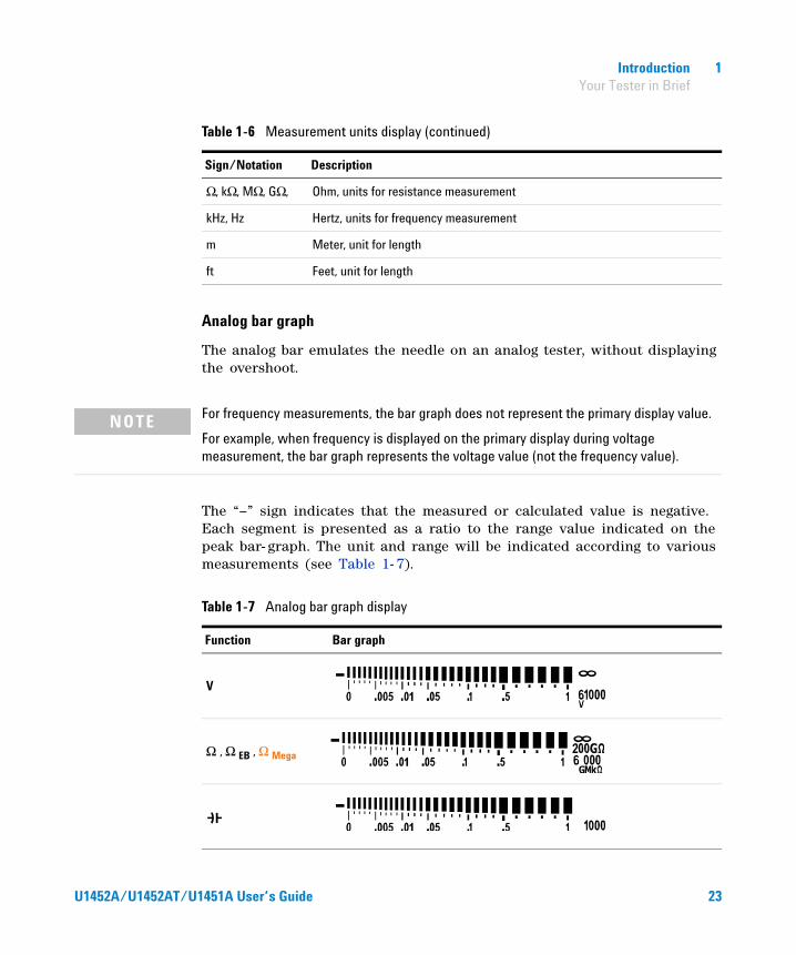
Analog bar graph
The analog bar emulates the needle on an analog tester, without displaying the overshoot.
The “–” sign indicates that the measured or calculated value is negative. Each segment is presented as a ratio to the range value indicated on the peak bar- graph. The unit and range will be indicated according to various measurements (see Table 1- 7).
Ω, kΩ, MΩ, GΩ, Ohm, units for resistance measurement
kHz, Hz Hertz, units for frequency measurement
m Meter, unit for length
ft Feet, unit for length
Table 1-6 Measurement units display (continued)
Sign/Notation Description
NOTE For frequency measurements, the bar graph does not represent the primary display value.
For example, when frequency is displayed on the primary display during voltage measurement, the bar graph represents the voltage value (not the frequency value).
Table 1-7 Analog bar graph display
Function Bar graph
V
Ω , Ω EB , Ω Mega
U1452A/U1452AT/U1451A User’s Guide 23

1 Introduction Your Tester in Brief
Input terminals
The terminal connections for the different measurement functions of your tester are described in the table below.
WARNING To avoid damaging this device, do not exceed the input limit.
Table 1-8 Terminal connections for different measuring functions
Rotary switch position Input terminals Overload protection
1000 Vrms
1000 Vrms for short circuit <0.3 A
440 mA/1000 V, 30 kA fast-acting fuse
Figure 1-6 Connecting the remote switch probe
The remote switch probe is used for insulation resistance (IR) and earth-bond resistance (EBR) tests.
Remote switch probe terminal for IR and EBR tests
24 U1452A/U1452AT/U1451A User’s Guide
Introduction 1 Cleaning Your Tester
Cleaning Your Tester
Dirt or moisture in the terminals can distort readings. Follow the steps below to clean your tester.
1 Turn the tester off, and remove the test leads.
2 Turn the tester over, and shake out any dirt that may have accumulated in the terminals.
Wipe the case with a damp cloth and mild detergent — do not use abrasives or solvents. Wipe the contacts in each terminal with a clean swab dipped in alcohol.
WARNING To avoid electrical shock or damage to the tester, ensure that the insides of the casing stay dry at all times.
U1452A/U1452AT/U1451A User’s Guide 25
1 Introduction Additional Features
Additional Features
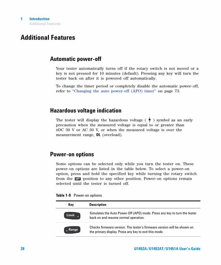
Automatic power-off
Your tester automatically turns off if the rotary switch is not moved or a key is not pressed for 10 minutes (default). Pressing any key will turn the tester back on after it is powered off automatically.
To change the timer period or completely disable the automatic power- off, refer to “Changing the auto power- off (APO) timer” on page 73.
Hazardous voltage indication
The tester will display the hazardous voltage ( ) symbol as an early precaution when the measured voltage is equal to or greater than ±DC 30 V or AC 30 V, or when the measured voltage is over the measurement range, OL (overload).
Power-on options
Some options can be selected only while you turn the tester on. These power- on options are listed in the table below. To select a power- on option, press and hold the specified key while turning the rotary switch from the position to any other position. Power- on options remain selected until the tester is turned off.
Table 1-9 Power-on options
Key Description
Simulates the Auto Power-Off (APO) mode. Press any key to turn the tester back on and resume normal operation.
Checks firmware version. The tester’s firmware version will be shown on the primary display. Press any key to exit this mode.
26 U1452A/U1452AT/U1451A User’s Guide
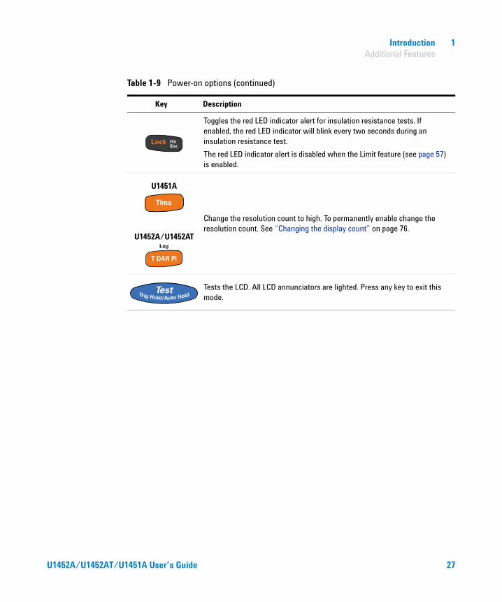
Introduction 1 Additional Features
Toggles the red LED indicator alert for insulation resistance tests. If enabled, the red LED indicator will blink every two seconds during an insulation resistance test.
The red LED indicator alert is disabled when the Limit feature (see page 57) is enabled.
‘
Change the resolution count to high. To permanently enable change the resolution count. See “Changing the display count” on page 76.
Tests the LCD. All LCD annunciators are lighted. Press any key to exit this mode.
Table 1-9 Power-on options (continued)
Key Description
U1452A/U1452AT
U1451A
U1452A/U1452AT/U1451A User’s Guide 27

1 Introduction Additional Features
THIS PAGE HAS BEEN INTENTIONALLY LEFT BLANK.
28 U1452A/U1452AT/U1451A User’s Guide
U1452A/U1452AT/U1451A Insulation TesterUser’s Guide
2Making Measurements
Insulation Resistance Test 30Using the Remote Switch Probe 32Locking the test 33Timed insulation resistance/earth-bond resistance test 34Measuring the Dielectric Absorption Ratio (DAR) 35Measuring the Polarization Index (PI) 36Viewing the leakage current 37
Earth-Bond Resistance Test 38
Measuring AC or DC Voltage 41Auto AC or DC signal identification 43
Measuring Frequency 44
Measuring Resistance 46
Continuity Test 48
Measuring Capacitance 50
The following sections describe how to take measurements with your tester.
29Agilent Technologies

2 Making Measurements Insulation Resistance Test
Insulation Resistance Test
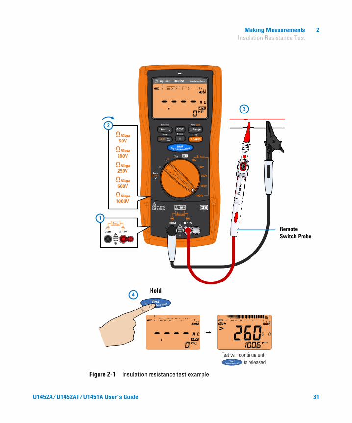
Set up your tester as shown in Figure 2- 1. Set the rotary switch to a test voltage value that does not exceed the maximum voltage limitation of the circuit under test. Ensure that the device- under- test (DUT) is de- energized before performing any resistance measurement.
Table 2-1 Rotary switch position for insulation resistance tests
Legend Default function Function when is pressed
Rotary switch position
Primary display Secondary display
Primary display Secondary display
50 V insulation resistance test
AC+DC V
or
DC V (during test)
1 Timed (T) test2 Dielectric
Absorption Ratio (DAR) test
3 Polarization Index (PI) test
AC+DC V
or
DC V (during test)
100 V insulation resistance test
250 V insulation resistance test
500 V insulation resistance test
1000 V insulation resistance test
CAUTION • DO NOT perform insulation resistance test in distribution systems with voltages higher than 600 V.
• The tester automatically detects if the circuit is energized. If the external voltage is detected to be greater than 30 V (or 50 V or 75 V; depending on selected option in Setup), the test is inhibited. The symbol is shown on the display when either the external voltage or the test voltage is greater than 30 V. Disconnect the tester and remove the power of the circuit before proceeding.
30 U1452A/U1452AT/U1451A User’s Guide
Making Measurements 2 Insulation Resistance Test
Figure 2-1 Insulation resistance test example
3
2
1
4
Remote Switch Probe
Hold
Test will continue until is released.
U1452A/U1452AT/U1451A User’s Guide 31
2 Making Measurements Insulation Resistance Test
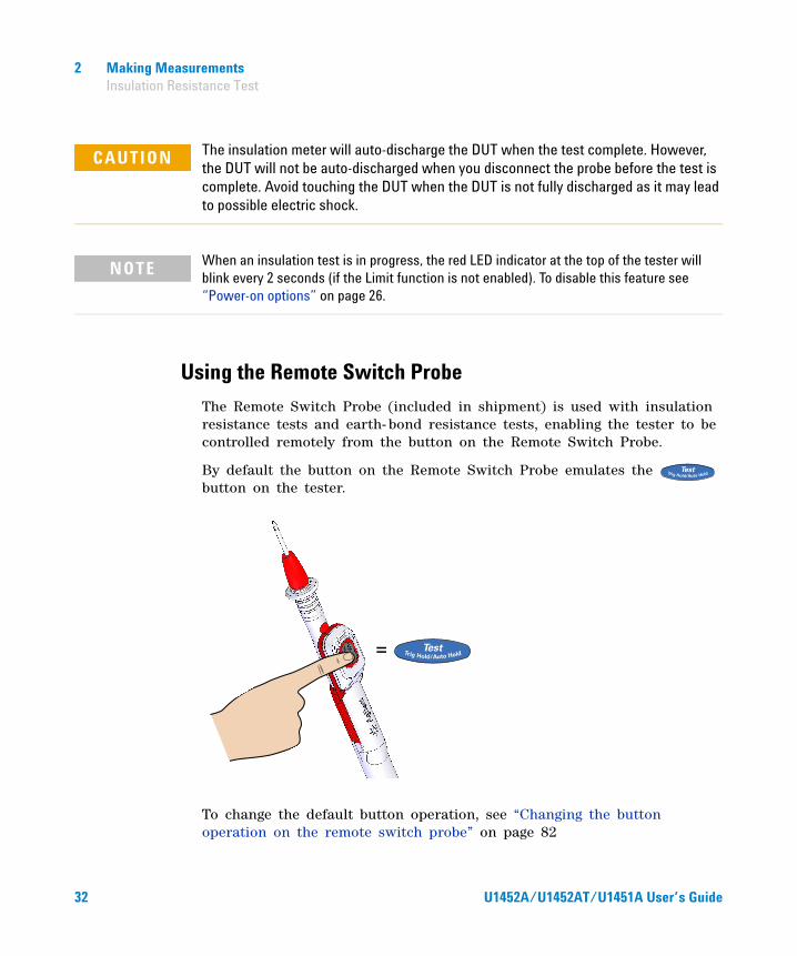
Using the Remote Switch Probe
The Remote Switch Probe (included in shipment) is used with insulation resistance tests and earth- bond resistance tests, enabling the tester to be controlled remotely from the button on the Remote Switch Probe.
By default the button on the Remote Switch Probe emulates the button on the tester.
To change the default button operation, see “Changing the button operation on the remote switch probe” on page 82
CAUTION The insulation meter will auto-discharge the DUT when the test complete. However, the DUT will not be auto-discharged when you disconnect the probe before the test is complete. Avoid touching the DUT when the DUT is not fully discharged as it may lead to possible electric shock.
NOTE When an insulation test is in progress, the red LED indicator at the top of the tester will blink every 2 seconds (if the Limit function is not enabled). To disable this feature see “Power-on options” on page 26.
=
32 U1452A/U1452AT/U1451A User’s Guide
Making Measurements 2 Insulation Resistance Test
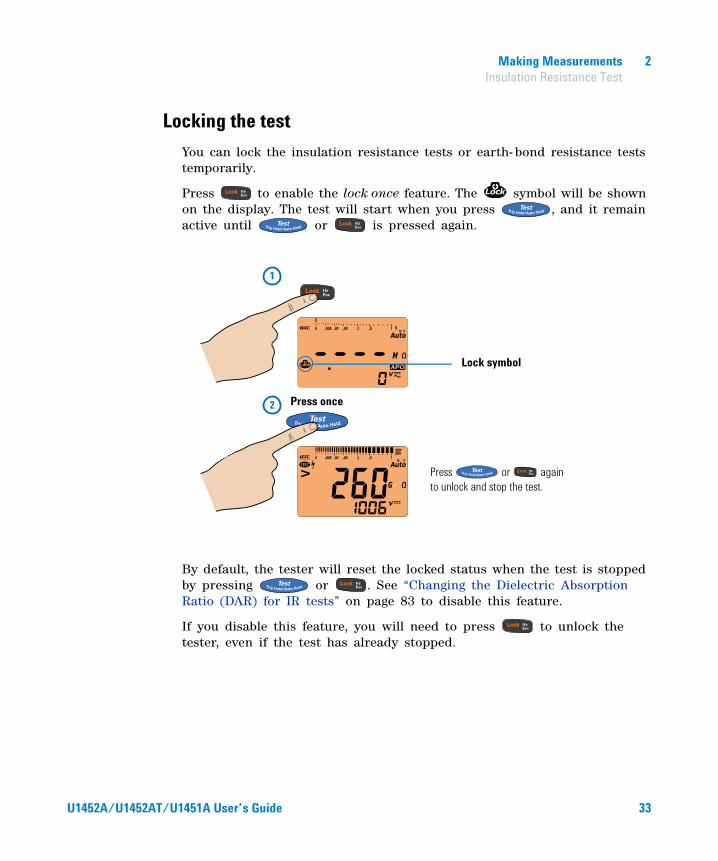
Locking the test
You can lock the insulation resistance tests or earth- bond resistance tests temporarily.
Press to enable the lock once feature. The symbol will be shown on the display. The test will start when you press , and it remain active until or is pressed again.
By default, the tester will reset the locked status when the test is stopped by pressing or . See “Changing the Dielectric Absorption Ratio (DAR) for IR tests” on page 83 to disable this feature.
If you disable this feature, you will need to press to unlock the tester, even if the test has already stopped.
2
1
Press once
Press or again to unlock and stop the test.
Lock symbol
U1452A/U1452AT/U1451A User’s Guide 33

2 Making Measurements Insulation Resistance Test
Timed insulation resistance/earth-bond resistance test
Use the timed test to obtain measurement results with consistent test times — for later comparisons. Set up your tester as shown in Figure 2- 1, and follow the steps shown below.
Figure 2-2 T/Time operation
Press / and select the timed test.
After 30 seconds.
After 1 minute, time up.
Press to view the resistance value.
Press to view the timer.
Press again to stop the test.
Press to start the test.
34 U1452A/U1452AT/U1451A User’s Guide
Making Measurements 2 Insulation Resistance Test
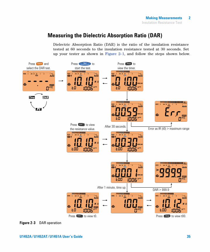
Measuring the Dielectric Absorption Ratio (DAR)
Dielectric Absorption Ratio (DAR) is the ratio of the insulation resistance tested at 60 seconds to the insulation resistance tested at 30 seconds. Set up your tester as shown in Figure 2- 1, and follow the steps shown below.
Figure 2-3 DAR operation
Press and select the DAR test.
Press to start the test.
After 30 seconds.
After 1 minute, time up.
Press to view t0. Press to view t00.
DAR > 999.9
Error as IR (t0) > maximum range
Press to view the timer.
Press to view the resistance value.
U1452A/U1452AT/U1451A User’s Guide 35

2 Making Measurements Insulation Resistance Test
Measuring the Polarization Index (PI)
Polarization Index (PI) is the ratio of the insulation resistance tested at 10 minutes to the insulation resistance tested at 1 minute. Set up your tester as shown in Figure 2- 1, and follow the steps shown below.
Figure 2-4 PI operation
Press and select the PI test.
Press to start the test.
After 1 minute.
After 10 minutes, time up.
Press to view t0. Press to view t00.
PI > 999.9
Press to view the timer.
Press to view the resistance value. Error as IR (t0) > maximum range
36 U1452A/U1452AT/U1451A User’s Guide

Making Measurements 2 Insulation Resistance Test
Viewing the leakage current
Press to view the leakage current display. The leakage current display is related to the insulation resistance. The higher the resistance tested, the lower the current is to be measured.
NOTE • Because of the time required to perform the T, PI, and DAR tests, the use of alligator test clips is recommended.
• For timed (page 34) tests, The length of the timer is 1 minute by default. To change this value, see “Changing the IR and EBR test period” on page 80 for more information.
• For DAR (page 35) tests, you can change the DAR from 60:30 to 60:15 in the Setup. See “Changing the Dielectric Absorption Ratio (DAR) for IR tests” on page 83 for more information.
• For DAR (page 35) and PI (page 36) tests, Err is shown on the display if the IR is greater than the maximum range or less than 0.001 MΩ; if the test is interrupted by the user; or if the tester’s battery is low.
U1452A/U1452AT/U1451A User’s Guide 37

2 Making Measurements Earth-Bond Resistance Test
Earth-Bond Resistance Test
Set up your tester to perform earth- bond resistance tests as shown in Figure 2- 5.
Table 2-2 Earth-bond resistance test position
Legend Default function Function when is pressed
Rotary switch position
Primary displaySecondary display
Primary displaySecondary display
Earth-bond resistance test
AC+DC V
or
DC V (during test)
Timed (T) test
AC+DC V
or
DC V (during test)
CAUTION • To avoid possible damage to your tester or to the equipment under test, disconnect the circuit power and discharge all high-voltage capacitors before measuring resistance.
• The tester automatically detects if the circuit is energized. If the external voltage is detected to be greater than 2 V, the test will not start. Disconnect the tester and remove power before proceeding.
NOTE • The earth-bond resistance function is used to measure the resistance between earth conductors, protective earth conductors, and conductors for equipotential bonding; including their connections and terminals; with an indication of the measured value or indication of limits.
• The voltage source is <6.8 V, and the current is >200 mA when the resistance of ≤2 Ω is to be measured. When the source voltage is <4.7 V, the tester will inhibit the test automatically. The secondary display indicates the voltage (with auto-ranging enabled).
• The APO (auto power-off) function is disabled during the test.
• See also “Timed insulation resistance/earth-bond resistance test” on page 34.
38 U1452A/U1452AT/U1451A User’s Guide

Making Measurements 2 Earth-Bond Resistance Test
Figure 2-5 Earth-bond resistance test example
3
2
1
4>
Remote Switch Probe
Hold
Test will continue until is released.
OR
U1452A/U1452AT/U1451A User’s Guide 39
2 Making Measurements Earth-Bond Resistance Test
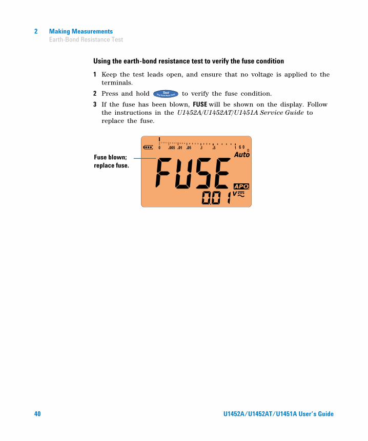
Using the earth-bond resistance test to verify the fuse condition
1 Keep the test leads open, and ensure that no voltage is applied to the terminals.
2 Press and hold to verify the fuse condition.
3 If the fuse has been blown, FUSE will be shown on the display. Follow the instructions in the U1452A/U1452AT/U1451A Service Guide to replace the fuse.
Fuse blown; replace fuse.
40 U1452A/U1452AT/U1451A User’s Guide
Making Measurements 2 Measuring AC or DC Voltage
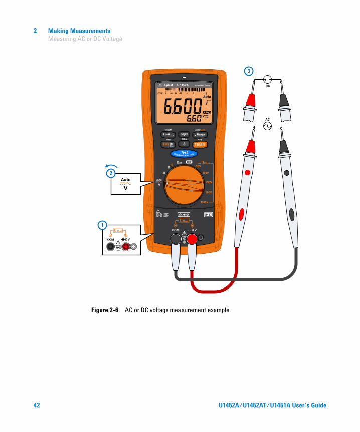
Measuring AC or DC Voltage
Set up your tester to measure AC or DC voltage as shown in Figure 2- 6.
Table 2-3 AC and DC voltage measurement positions
Legend Default function Function when is pressed
Rotary switch position
Primary displaySecondary display
Primary displaySecondary display
Auto (V) AC+DC V
Cycles between
1 DC V2 AC V3 Auto (V)
1 AC+DC V2 AC+DC V3 AC+DC V
NOTE • This tester displays DC voltage values as well as their polarity. Negative DC voltages will return a negative sign on the left of the display.
• Press to measure the frequency of the voltage source. See “Measuring Frequency” on page 44 to learn more.
U1452A/U1452AT/U1451A User’s Guide 41
2 Making Measurements Measuring AC or DC Voltage
Figure 2-6 AC or DC voltage measurement example
AC
3
DC
2
1
42 U1452A/U1452AT/U1451A User’s Guide
Making Measurements 2 Measuring AC or DC Voltage
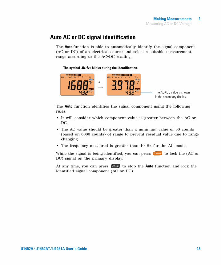
Auto AC or DC signal identification
The Auto function is able to automatically identify the signal component (AC or DC) of an electrical source and select a suitable measurement range according to the AC+DC reading.
The Auto function identifies the signal component using the following rules:
• It will consider which component value is greater between the AC or DC.
• The AC value should be greater than a minimum value of 50 counts (based on 6000 counts) of range to prevent residual value due to range changing.
• The frequency measured is greater than 10 Hz for the AC mode.
While the signal is being identified, you can press to lock the (AC or DC) signal on the primary display.
At any time, you can press to stop the Auto function and lock the identified signal component (AC or DC).
The symbol blinks during the identification.
The AC+DC value is shown in the secondary display.
U1452A/U1452AT/U1451A User’s Guide 43
2 Making Measurements Measuring Frequency
Measuring Frequency
Your tester allows simultaneous monitoring of real- time voltage with frequency measurements. To measure frequency, rotate the switch to measure voltage (see Figure 2- 6) and set up the tester accordingly.
Press . Probe the test points, and read the display.
Frequency measurement techniques
• Measuring the frequency of a signal helps detect the presence of harmonic currents in neutral conductors and determines whether these neutral currents are the result of unbalanced phases or non- linear loads.
• Frequency is the number of cycles a signal completes each second. Frequency is defined as 1/Period. Period is defined as the time between the middle threshold crossings of two consecutive, like- polarity edges, as shown in Figure 2- 7.
• The tester measures the frequency of a voltage signal by counting the number of times the signal crosses a threshold level within a specified period of time.
• If a reading shows as 0 Hz or is unstable, the input signal may be below or near the trigger level. You can usually correct these problems by manually selecting a lower input range, which increases the sensitivity of the tester.
WARNING Never measure the frequency where the voltage level exceeds the specified range. Manually set the voltage range if you want to measure frequencies below 20 Hz.
NOTE • Pressing controls the input range of the voltage function and not the frequency range.
• To obtain the best measuring results for frequency measurements, please use the AC measuring path.
44 U1452A/U1452AT/U1451A User’s Guide

Making Measurements 2 Measuring Frequency
• If a reading seems to be a multiple of what you expect, the input signal may be distorted. Distortion can cause multiple triggerings of the frequency counter. Selecting a higher voltage range might solve this problem by decreasing the sensitivity of the tester. In general, the lowest frequency displayed is the correct one.
• The frequency of the input signal is shown in the primary display. The voltage value of the signal is shown in the secondary display. The bar graph does not indicate frequency but indicates the voltage value of the input signal.
Figure 2-7 Definition of frequency
Rise Time Fall Time
+ Width – Width
Period
90%
50%
10%
U1452A/U1452AT/U1451A User’s Guide 45
2 Making Measurements Measuring Resistance
Measuring Resistance
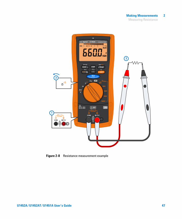
Set up your tester to measure resistance as shown in Figure 2- 8.
Table 2-4 Resistance measurement position
Legend Default function Function when is pressed
Rotary switch position
Primary displaySecondary display
Primary displaySecondary display
Resistance - Continuity -
CAUTION To avoid possible damage to your tester or to the equipment under test, disconnect the circuit power and discharge all high-voltage capacitors before measuring resistance.
NOTE Resistance (opposition to the current flow) is measured by sending a small current out through the test leads to the circuit under test. Because this current flows through all possible paths between the leads, the resistance reading represents the total resistance of all paths between the leads. Resistance is measured in ohms (Ω).
Keep the following in mind when measuring resistance.
• The test leads can add 0.1 Ω to 0.2 Ω of error to resistance measurements. To test the leads, touch the probe tips together and read the resistance of the leads. To remove lead resistance from the measurement, hold the test lead tips together and press . Now the resistance at the probe tips will be subtracted from all future display readings.
• Because the tester’s test current flows through all possible paths between the probe tips, the measured value of a resistor in a circuit is often different from the resistor’s rated value.
46 U1452A/U1452AT/U1451A User’s Guide
Making Measurements 2 Measuring Resistance
Figure 2-8 Resistance measurement example
3
2
1
U1452A/U1452AT/U1451A User’s Guide 47
2 Making Measurements Continuity Test
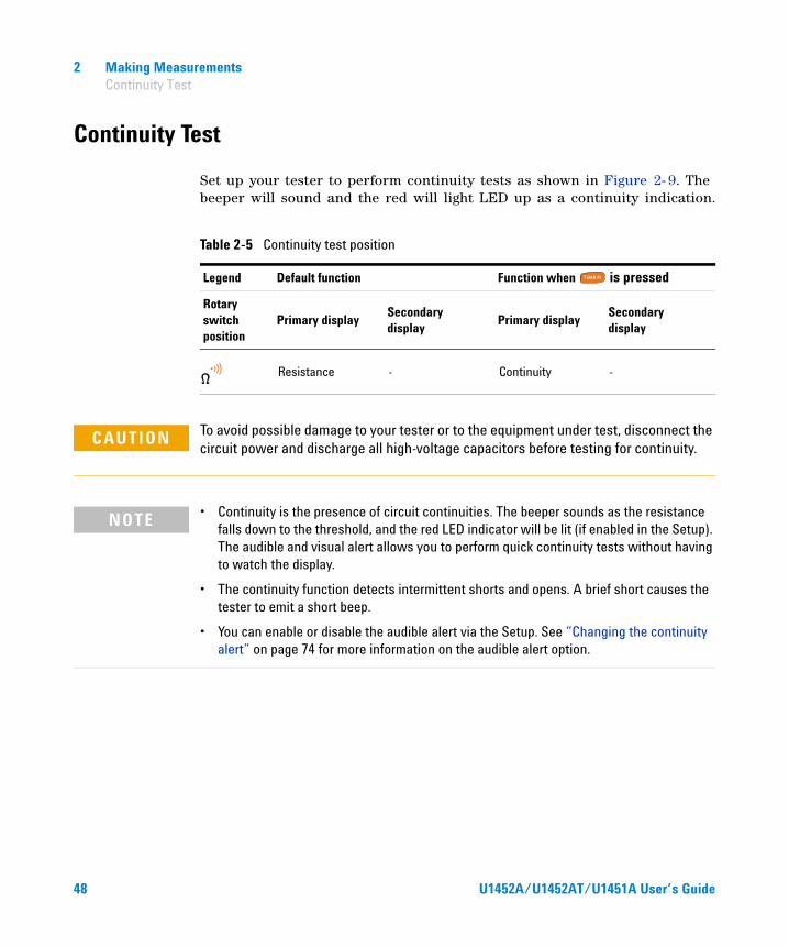
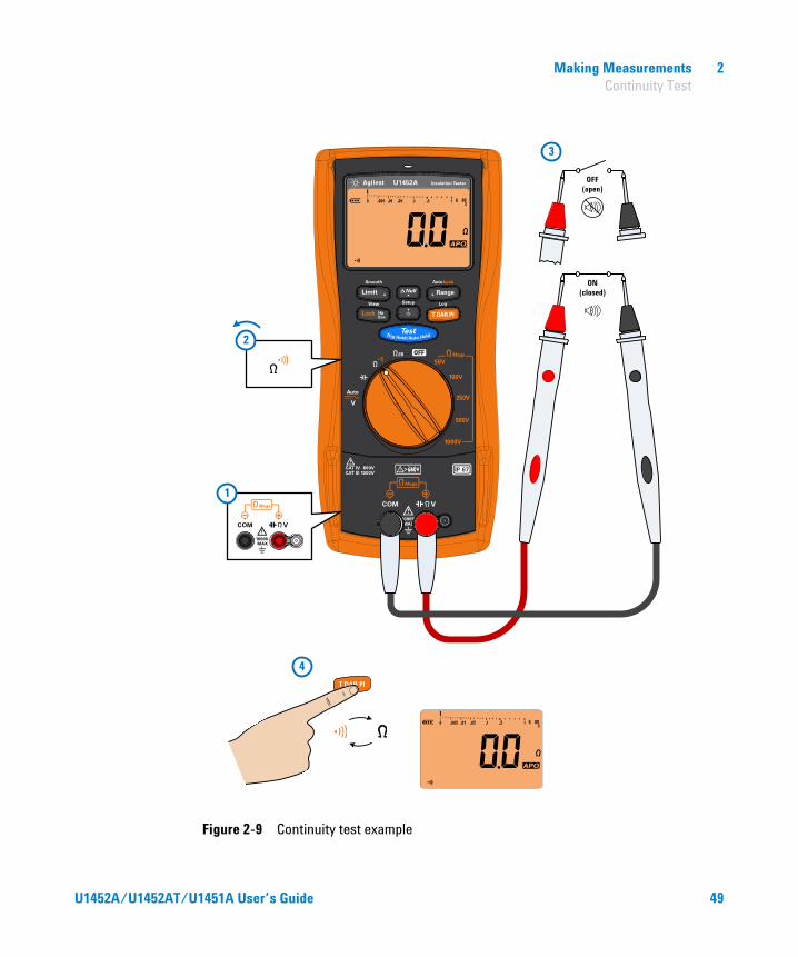
Continuity Test
Set up your tester to perform continuity tests as shown in Figure 2- 9. The beeper will sound and the red will light LED up as a continuity indication.
Table 2-5 Continuity test position
Legend Default function Function when is pressed
Rotary switch position
Primary displaySecondary display
Primary displaySecondary display
Resistance - Continuity -
CAUTION To avoid possible damage to your tester or to the equipment under test, disconnect the circuit power and discharge all high-voltage capacitors before testing for continuity.
NOTE • Continuity is the presence of circuit continuities. The beeper sounds as the resistance falls down to the threshold, and the red LED indicator will be lit (if enabled in the Setup). The audible and visual alert allows you to perform quick continuity tests without having to watch the display.
• The continuity function detects intermittent shorts and opens. A brief short causes the tester to emit a short beep.
• You can enable or disable the audible alert via the Setup. See “Changing the continuity alert” on page 74 for more information on the audible alert option.
48 U1452A/U1452AT/U1451A User’s Guide
Making Measurements 2 Continuity Test
Figure 2-9 Continuity test example
2
1
3
ON (closed)
OFF (open)
4
U1452A/U1452AT/U1451A User’s Guide 49

2 Making Measurements Measuring Capacitance
Measuring Capacitance
Set up your tester to measure capacitance as shown in Figure 2- 10. The cable length of the circuit under test in shown in the secondary display.
• The default cable length scale is 1 km per 40 nF (km/C). To change this value, see “Changing the cable length scale” on page 78.
• You can also change the cable length unit (Meter or Feet). To change this value, see “Changing the cable length unit” on page 77.
Table 2-6 Capacitance measurement position
Legend Default function Function when is pressed
Rotary switch position
Primary displaySecondary display
Primary displaySecondary display
Capacitance Cable length - -
CAUTION To avoid possible damage to the tester or to the equipment under test, disconnect circuit power and discharge all high-voltage capacitors before measuring capacitance. Use the DC voltage function to confirm that the capacitor is fully discharged.
NOTE • The tester measures capacitance by using an AC sine wave.
• The resistance of the test leads will impact the accuracy of the measurement. It is recommended to use short leads to measure capacitance.
• The test frequency is 54.5 Hz.
50 U1452A/U1452AT/U1451A User’s Guide

Making Measurements 2 Measuring Capacitance
Figure 2-10 Capacitance measurement example
1
3
+ –
2
U1452A/U1452AT/U1451A User’s Guide 51

2 Making Measurements Measuring Capacitance
THIS PAGE HAS BEEN INTENTIONALLY LEFT BLANK.
52 U1452A/U1452AT/U1451A User’s Guide
U1452A/U1452AT/U1451A Insulation TesterUser’s Guide
3Tester Features
Making Relative Measurements (Null) 54
Freezing the Display (TrigHold and AutoHold) 55
Performing Limit Comparisons (Limit) 57
Recording Measurement Data (Log) 59Performing manual logs (HAND) 60Performing interval logs (AUTO) 60Performing event logs (TRIG) 61
Reviewing Previously Recorded Data (View) 63
The following sections describe the additional features available in your tester.
53Agilent Technologies
3 Tester Features Making Relative Measurements (Null)
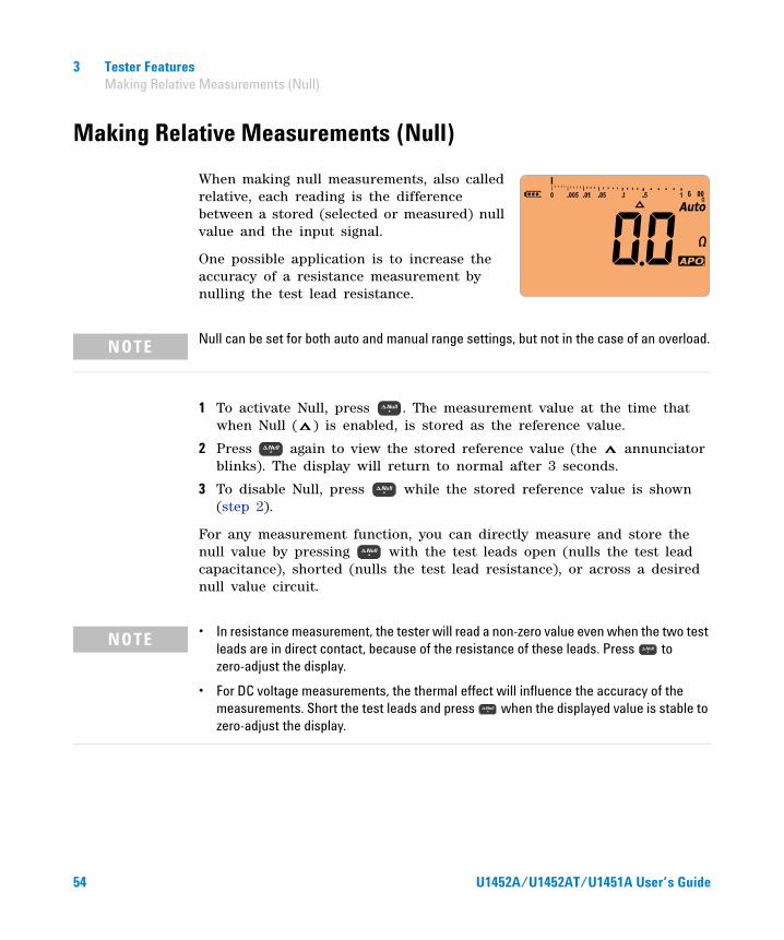
Making Relative Measurements (Null)
When making null measurements, also called relative, each reading is the difference between a stored (selected or measured) null value and the input signal.
One possible application is to increase the accuracy of a resistance measurement by nulling the test lead resistance.
1 To activate Null, press . The measurement value at the time that when Null ( ) is enabled, is stored as the reference value.
2 Press again to view the stored reference value (the annunciator blinks). The display will return to normal after 3 seconds.
3 To disable Null, press while the stored reference value is shown (step 2).
For any measurement function, you can directly measure and store the null value by pressing with the test leads open (nulls the test lead capacitance), shorted (nulls the test lead resistance), or across a desired null value circuit.
NOTE Null can be set for both auto and manual range settings, but not in the case of an overload.
NOTE • In resistance measurement, the tester will read a non-zero value even when the two test leads are in direct contact, because of the resistance of these leads. Press to zero-adjust the display.
• For DC voltage measurements, the thermal effect will influence the accuracy of the measurements. Short the test leads and press when the displayed value is stable to zero-adjust the display.
54 U1452A/U1452AT/U1451A User’s Guide
Tester Features 3 Freezing the Display (TrigHold and AutoHold)
Freezing the Display (TrigHold and AutoHold)
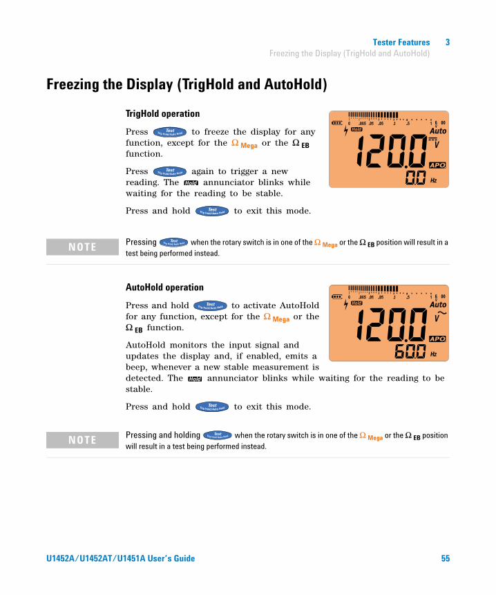
TrigHold operation
Press to freeze the display for any function, except for the Ω Mega or the Ω EB function.
Press again to trigger a new reading. The annunciator blinks while waiting for the reading to be stable.
Press and hold to exit this mode.
AutoHold operation
Press and hold to activate AutoHold for any function, except for the Ω Mega or the Ω EB function.
AutoHold monitors the input signal and updates the display and, if enabled, emits a beep, whenever a new stable measurement is detected. The annunciator blinks while waiting for the reading to be stable.
Press and hold to exit this mode.
NOTE Pressing when the rotary switch is in one of the Ω Mega or the Ω EB position will result in a test being performed instead.
NOTE Pressing and holding when the rotary switch is in one of the Ω Mega or the Ω EB position will result in a test being performed instead.
U1452A/U1452AT/U1451A User’s Guide 55

3 Tester Features Freezing the Display (TrigHold and AutoHold)
A trigger point is one that varies more than a selected adjustable (AutoHold threshold) variation count (default 500 counts). The following conditions are not included in the update.
To change the default AutoHold threshold count see “Changing the variation count” on page 71 for more information.
Function None updated counts
Voltage 50
Resistance OL or Open
Capacitance 50
NOTE If the reading value is unable to reach a stable state, the reading value will not be updated.
56 U1452A/U1452AT/U1451A User’s Guide
Tester Features 3 Performing Limit Comparisons (Limit)
Performing Limit Comparisons (Limit)
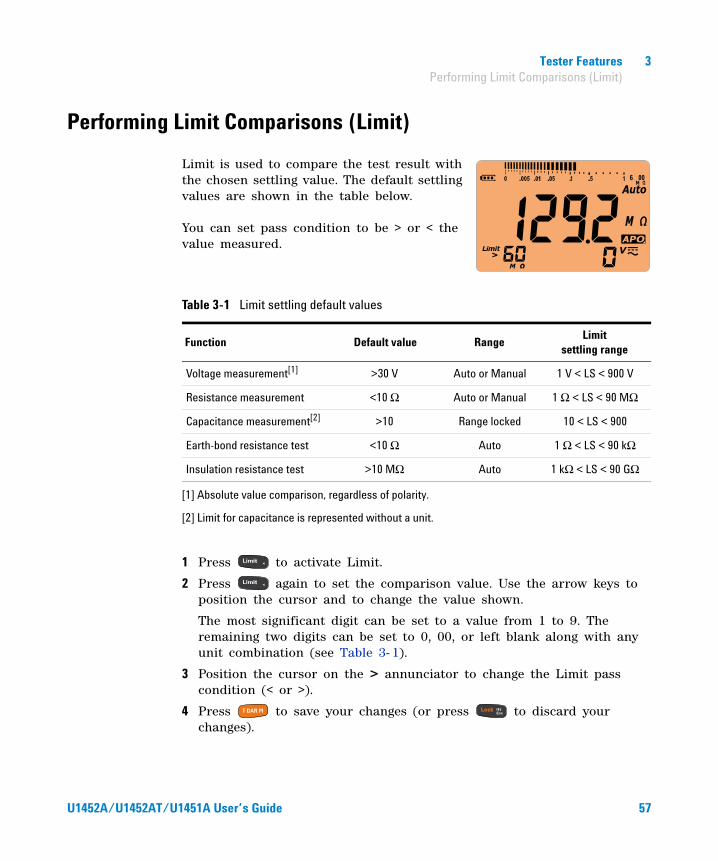
Limit is used to compare the test result with the chosen settling value. The default settling values are shown in the table below. You can set pass condition to be > or < the value measured.
1 Press to activate Limit.
2 Press again to set the comparison value. Use the arrow keys to position the cursor and to change the value shown.
The most significant digit can be set to a value from 1 to 9. The remaining two digits can be set to 0, 00, or left blank along with any unit combination (see Table 3- 1).
3 Position the cursor on the > annunciator to change the Limit pass condition (< or >).
4 Press to save your changes (or press to discard your changes).
Table 3-1 Limit settling default values
Function Default value RangeLimit
settling range
Voltage measurement[1]
[1] Absolute value comparison, regardless of polarity.
>30 V Auto or Manual 1 V < LS < 900 V
Resistance measurement <10 Ω Auto or Manual 1 Ω < LS < 90 MΩ
Capacitance measurement[2]
[2] Limit for capacitance is represented without a unit.
>10 Range locked 10 < LS < 900
Earth-bond resistance test <10 Ω Auto 1 Ω < LS < 90 kΩ
Insulation resistance test >10 MΩ Auto 1 kΩ < LS < 90 GΩ
U1452A/U1452AT/U1451A User’s Guide 57
3 Tester Features Performing Limit Comparisons (Limit)
5 If the new value is passed:
• is shown
• A short beep tone is heard
• The red LED blinks once
6 If the new value is failed:
• is shown
• Three short beep tones are heard
• The red LED blinks thrice
NOTE When the Limit feature is enabled for insulation resistance tests, the red LED indicator lights up accordingly to the changes in the limit values instead of blinking every 2 seconds.
58 U1452A/U1452AT/U1451A User’s Guide

Tester Features 3 Recording Measurement Data (Log)
Recording Measurement Data (Log)
Log provides you with the convenience of recording test data for future review or analysis. Since data is stored in the nonvolatile memory, the data remains saved even when the tester is turned OFF or if the battery is replaced.
Log collects measurement information over a user- specified duration. There are three Log options that can be used to capture measurement data: manual (HAND), interval (AUTO), or event (TRIG).
• A manual log stores an instance of the measured signal each time you press and hold (see page 60).
• An interval log stores a record of the measured signal at a user- specified interval (see page 60).
• An event log stores a record of the measured signal each time a trigger condition is satisfied (see page 61).
Before starting a recording session, set up the tester for the measurements to be recorded.
To change the Log option see “Changing the recording option” on page 80 for more information.
See “Reviewing Previously Recorded Data (View)” on page 63 to review or erase the recorded entries.
Table 3-2 Log maximum capacity
Log option Maximum capacity for saving
Manual (HAND) H00 to H99 (100 entries)
Interval (AUTO) A00 to A99 (100 entries)
Event (TRIG) E00 to E99 (100 entries)
NOTE Each recorded index includes two parameters: the primary display and the secondary display. Examples include IR-V or V-Hz.
U1452A/U1452AT/U1451A User’s Guide 59
3 Tester Features Recording Measurement Data (Log)
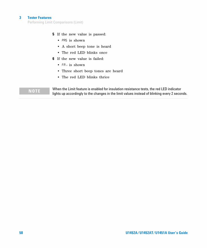
Performing manual logs (HAND)
Ensure that is selected as the Log option in the Setup.
1 Press and hold to store the present input signal value.
and the log entry number are displayed. The display will return to normal after a short while (around 1 second).
2 Repeat step 1 again to save the next input signal value.
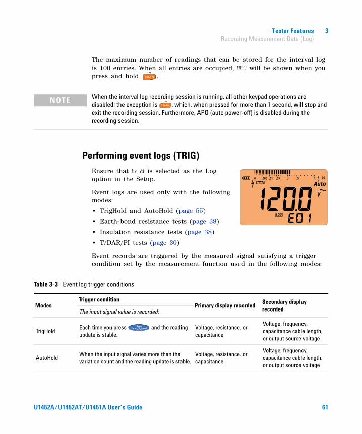
The maximum number of readings that can be stored for the manual log is 100 entries. When all entries are occupied, will be shown when you press and hold .
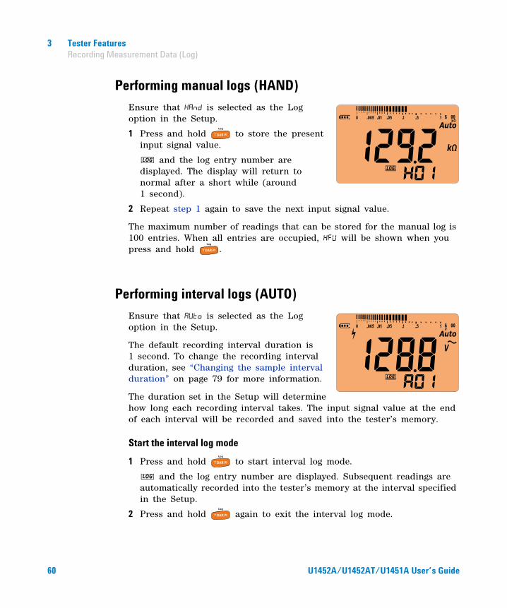
Performing interval logs (AUTO)
Ensure that is selected as the Log option in the Setup.
The default recording interval duration is 1 second. To change the recording interval duration, see “Changing the sample interval duration” on page 79 for more information.
The duration set in the Setup will determine how long each recording interval takes. The input signal value at the end of each interval will be recorded and saved into the tester’s memory.
Start the interval log mode
1 Press and hold to start interval log mode.
and the log entry number are displayed. Subsequent readings are automatically recorded into the tester’s memory at the interval specified in the Setup.
2 Press and hold again to exit the interval log mode.
60 U1452A/U1452AT/U1451A User’s Guide
Tester Features 3 Recording Measurement Data (Log)
The maximum number of readings that can be stored for the interval log is 100 entries. When all entries are occupied, will be shown when you press and hold .
Performing event logs (TRIG)
Ensure that is selected as the Log option in the Setup.
Event logs are used only with the following modes:
• TrigHold and AutoHold (page 55)
• Earth- bond resistance tests (page 38)
• Insulation resistance tests (page 38)
• T/DAR/PI tests (page 30)
Event records are triggered by the measured signal satisfying a trigger condition set by the measurement function used in the following modes:
NOTE When the interval log recording session is running, all other keypad operations are disabled; the exception is , which, when pressed for more than 1 second, will stop and exit the recording session. Furthermore, APO (auto power-off) is disabled during the recording session.
Table 3-3 Event log trigger conditions
ModesTrigger condition
Primary display recordedSecondary display recordedThe input signal value is recorded:
TrigHoldEach time you press and the reading update is stable.
Voltage, resistance, or capacitance
Voltage, frequency, capacitance cable length, or output source voltage
AutoHoldWhen the input signal varies more than the variation count and the reading update is stable.
Voltage, resistance, or capacitance
Voltage, frequency, capacitance cable length, or output source voltage
U1452A/U1452AT/U1451A User’s Guide 61

3 Tester Features Recording Measurement Data (Log)
Start the event log mode
1 Select one of the modes listed in Table 3- 3.
2 Press and hold to start event log mode.
and the log entry number are displayed. The primary display and secondary display readings will be recorded into the memory. Subsequent readings are automatically recorded into the tester’s memory every time the trigger condition specified in Table 3- 3 is satisfied.
3 Press and hold again to exit the event log mode.
The maximum number of readings that can be stored for the event log is 100 entries. When all entries are occupied, will be shown when you press and hold .
Earth-bond resistance test Each time you press to stop the test
output source.Resistance or leak current value
Test output source voltageInsulation resistance test
T/TimeWhen the time is up (Timer = 00:00), the final value is recorded before the test output source is stopped.
Resistance or leak current value
Test output source voltage
NOTE The values of DAR t30 (or DAR t15), DAR t60, PI t1, and PI t10 will be recorded in every IR rotary switch location. For more information on DAR and PI tests, see page 35 and page 36 respectively.
Table 3-3 Event log trigger conditions (continued)
ModesTrigger condition
Primary display recordedSecondary display recordedThe input signal value is recorded:
NOTE APO (auto power-off) is disabled during the recording session.
62 U1452A/U1452AT/U1451A User’s Guide

Tester Features 3 Reviewing Previously Recorded Data (View)
Reviewing Previously Recorded Data (View)
Viewing data stored in the tester’s memory is performed through the key.
1 Press and hold to View the previously recorded data. Press again to cycle through the manual (), interval (), or event () records.
If nothing has been recorded, , , or will be displayed instead.
2 Select the desired recording category to view its entries.
i Press to jump to the first stored entry. Press to jump to the last stored entry.
ii Press to view the next stored entry. The index number increases by one. Press to view the previous stored entry. The index number decreases by one.
iii Press to clear the last stored entry for the selected log type. Press and hold to clear all entries for the selected log type.
3 Press and hold again to exit the View mode.
Sanitizing the Log Memories
You have the option to sanitize the log memories of your tester. This operation erases the log memories of your tester thoroughly. The data stored in the tester’s memory will not be able to be reconstructed in any way after the data sanitization operation.
Prior to sanitizing the log memories, ensure that all manual (), interval (), or event () records have been cleared (see step iii). When all entries are cleared (, , and ), press and hold to sanitize the log memories.
CAUTION The data sanitization operation may take up to 30 seconds to complete. Do not press any keys or turn the rotary switch until the data sanitization operation is completed.
U1452A/U1452AT/U1451A User’s Guide 63

3 Tester Features Reviewing Previously Recorded Data (View)
THIS PAGE HAS BEEN INTENTIONALLY LEFT BLANK.
64 U1452A/U1452AT/U1451A User’s Guide
U1452A/U1452AT/U1451A Insulation TesterUser’s Guide
4Setup Options
Using the Setup Menu 66Editing numerical values 67
Setup Menu Summary 68
Setup Menu Items 71Editing numerical values 67Changing the variation count 71Enabling smooth mode 71Changing the beep frequency 72Changing the auto power-off (APO) timer 73Changing the LCD backlight timeout 73Changing the continuity alert 74Disabling the power-on melody 75Changing the battery type 75Resetting the tester’s Setup options 76Changing the display count 76Changing the cable length unit 77Changing the cable length scale 78Changing the alert indicators 78Changing the sample interval duration 79Changing the recording option 80Changing the IR and EBR test period 80Changing the maximum inhibit voltage for IR tests 81Disabling the lock once feature 82Changing the button operation on the remote switch probe 82Changing the Dielectric Absorption Ratio (DAR) for IR tests 83
The following sections describe how to change the preset features of your tester.
65Agilent Technologies
4 Setup Options Using the Setup Menu
Using the Setup Menu
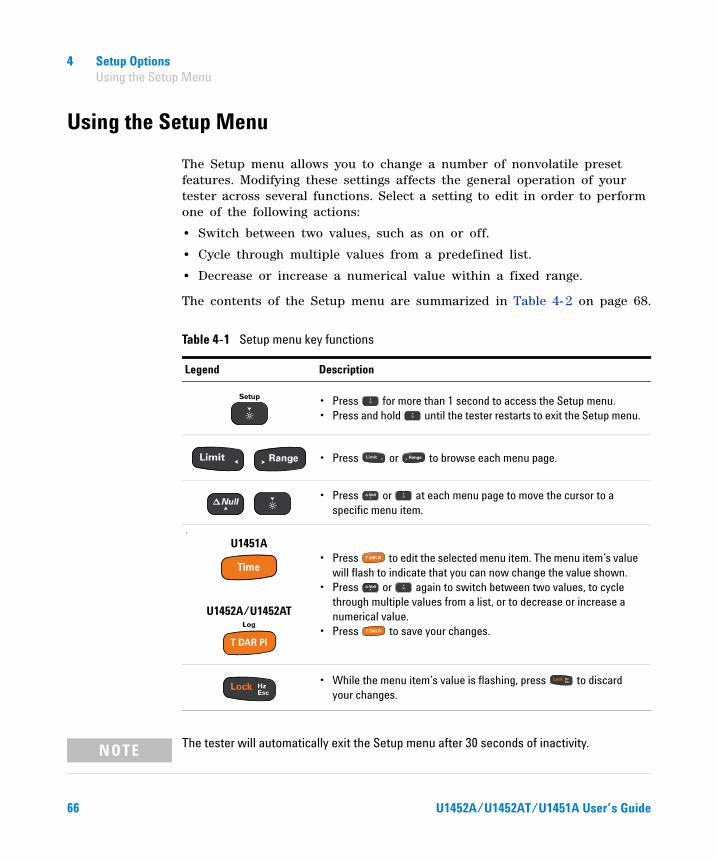
The Setup menu allows you to change a number of nonvolatile preset features. Modifying these settings affects the general operation of your tester across several functions. Select a setting to edit in order to perform one of the following actions:
• Switch between two values, such as on or off.
• Cycle through multiple values from a predefined list.
• Decrease or increase a numerical value within a fixed range.
The contents of the Setup menu are summarized in Table 4- 2 on page 68.
Table 4-1 Setup menu key functions
Legend Description
• Press for more than 1 second to access the Setup menu. • Press and hold until the tester restarts to exit the Setup menu.
• Press or to browse each menu page.
• Press or at each menu page to move the cursor to a specific menu item.
l‘
• Press to edit the selected menu item. The menu item’s value will flash to indicate that you can now change the value shown.
• Press or again to switch between two values, to cycle through multiple values from a list, or to decrease or increase a numerical value.
• Press to save your changes.
• While the menu item’s value is flashing, press to discard your changes.
U1451A
U1452A/U1452AT
NOTE The tester will automatically exit the Setup menu after 30 seconds of inactivity.
66 U1452A/U1452AT/U1451A User’s Guide

Setup Options 4 Using the Setup Menu
Editing numerical values
When editing numerical values, use the and to position the cursor on a numerical digit.
• Press to move the cursor to the left, and
• Press to move the cursor to the right.
When the cursor is positioned over a digit, use the and keys to change the numerical digit.
• Press to increment the digit, and
• Press to decrement the digit.
When you have completed your changes, save the new numerical value by pressing . (Or alternatively, if you wish to discard the changes you made, press .)
Press and hold for more than 1 second to enter the Setup menu.
Press to edit the selected menu item’s value.
Press or to move the cursor left or right.
Press or to increment or decrement the selected digit.
Press again to save the changes made.
U1452A/U1452AT/U1451A User’s Guide 67
4 Setup Options Setup Menu Summary
Setup Menu Summary
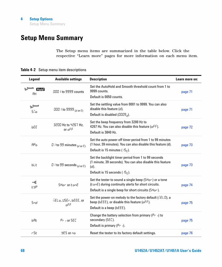
The Setup menu items are summarized in the table below. Click the respective “Learn more” pages for more information on each menu item.
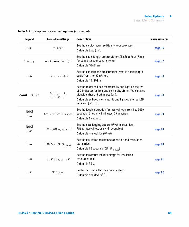
Table 4-2 Setup menu item descriptions
Legend Available settings Description Learn more on:
to counts
Set the AutoHold and Smooth threshold count from 1 to 9999 counts.
Default is 0050 counts.
page 71
to ( or )
Set the settling value from 0001 to 9999. You can also disable this feature ().
Default is disabled ().
page 71
Hz to Hz,
or
Set the beep frequency from 3200 Hz to 4267 Hz. You can also disable this feature ().
Default is 3840 Hz.
page 72
to minutes ( or )
Set the auto power-off timer period from 1 to 99 minutes (1 hour, 39 minutes). You can also disable this feature (d).
Default is 15 minutes ().
page 73
to seconds ( or )
Set the backlight timer period from 1 to 99 seconds (1 minute, 39 seconds). You can also disable this feature ().
Default is 15 seconds ().
page 73
or
Set the tester to sound a single beep () or a tone () during continuity alerts for short circuits.
Default is a single beep for short circuits ().
page 74
, , , or
Set the power-on melody to the factory default (), a beep (), or disable this feature ().
Default is a beep ().
page 75
or
Change the battery selection from primary () to secondary ().
Default is primary ().
page 75
or Reset the tester to its factory default settings. page 76
68 U1452A/U1452AT/U1451A User’s Guide
Setup Options 4 Setup Menu Summary
or Set the display count to High () or Low ().
Default is Low ().page 76
(m) or (ft)
Set the cable length unit to Meter () or Foot () for capacitance measurements.
Default is (m).
page 77
to nF/km
Set the capacitance measurement versus cable length scale from 1 to 99 nF/km.
Default is 40 nF/km.
page 78
., .,., or .
Set the tester to beep momentarily and light up the red LED indicator for limit and continuity alerts. You can also disable either or both alerts (off).
Default is to beep momentarily and light up the red LED indicator (.).
page 78
to seconds
Set the logging duration for interval logs from 1 to 9999 seconds (2 hours, 46 minutes, 39 seconds).
Default is 1 second.
page 79
, , or
Set the data logging option (: manual log, : interval log, or : event log).
Default is manual log ().
page 80
. to . mm:ss
Set the insulation resistance or earth-bond resistance test period.
Default is 10 seconds (. mm:ss)
page 80
V, V, or V
Set the maximum inhibit voltage for insulation resistance test.
Default is 30 V.
page 81
or Enable or disable the lock once feature.
Default is enabled ().page 82
Table 4-2 Setup menu item descriptions (continued)
Legend Available settings Description Learn more on:
U1452A/U1452AT/U1451A User’s Guide 69
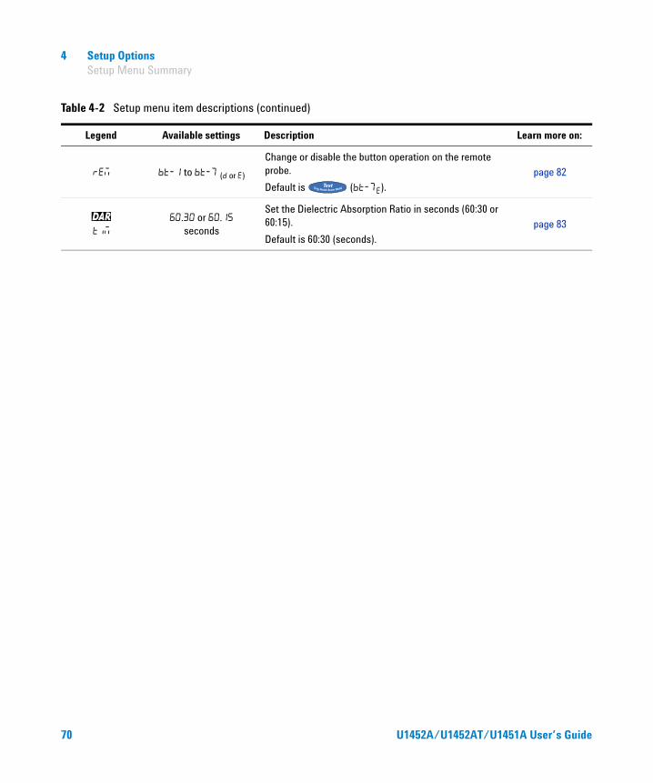
4 Setup Options Setup Menu Summary
to ( or )
Change or disable the button operation on the remote probe.
Default is ().
page 82
. or . seconds
Set the Dielectric Absorption Ratio in seconds (60:30 or 60:15).
Default is 60:30 (seconds).
page 83
Table 4-2 Setup menu item descriptions (continued)
Legend Available settings Description Learn more on:
70 U1452A/U1452AT/U1451A User’s Guide

Setup Options 4 Setup Menu Items
Setup Menu Items
Changing the variation count
This setting is used with the AutoHold feature (see page 55). When the variation of the measured value exceeds the value of the variation count, the AutoHold feature will be ready to trigger.
To change the variation count:
1 Press for more than 1 second to enter the Setup menu.
2 Browse to ( and are shown on the display), and press to edit the value.
3 Use the arrow keys to change the variation count.
4 Press to save your changes (or press to discard your changes).
5 Press and hold until the tester restarts to return to normal operation.
Enabling smooth mode
Smooth is used to smoothen the refresh rate of the readings in order to reduce the impact of unexpected noise and to help you achieve a stable reading.
The smooth refresh rate can be set from 0001 to 9999. The smooth time is defined as the set value +1. Smooth will be restarted when the variation count is exceeded, when the range is changed, or after a tester function or feature is enabled. The variation count is set to the value used for the AutoHold feature (see “Changing the variation count” on page 71).
Legend Range Default setting
( to ) counts
U1452A/U1452AT/U1451A User’s Guide 71

4 Setup Options Setup Menu Items
To change the smooth refresh rate:
1 Press for more than 1 second to enter the Setup menu.
2 Browse to ( is shown on the display), and press to edit the value.
3 Use the arrow keys to change the smooth refresh rate. Select to enable the Smooth feature.
4 Press to save your changes (or press to discard your changes).
5 Press and hold until the tester restarts to return to normal operation.
Changing the beep frequency
The beeper alerts users to the presence of circuit continuities and newly sensed values for Max Min recordings.
To change the beep frequency:
1 Press for more than 1 second to enter the Setup menu.
2 Browse to , and press to edit the value.
3 Use the arrow keys to change the beep frequency. Select to disable the beeper.
4 Press to save your changes (or press to discard your changes).
Legend Range Default setting
• to • (isabled) or (nabled)
Legend Range Default setting
(, , , , , , , , , , , , ) Hz, or
72 U1452A/U1452AT/U1451A User’s Guide
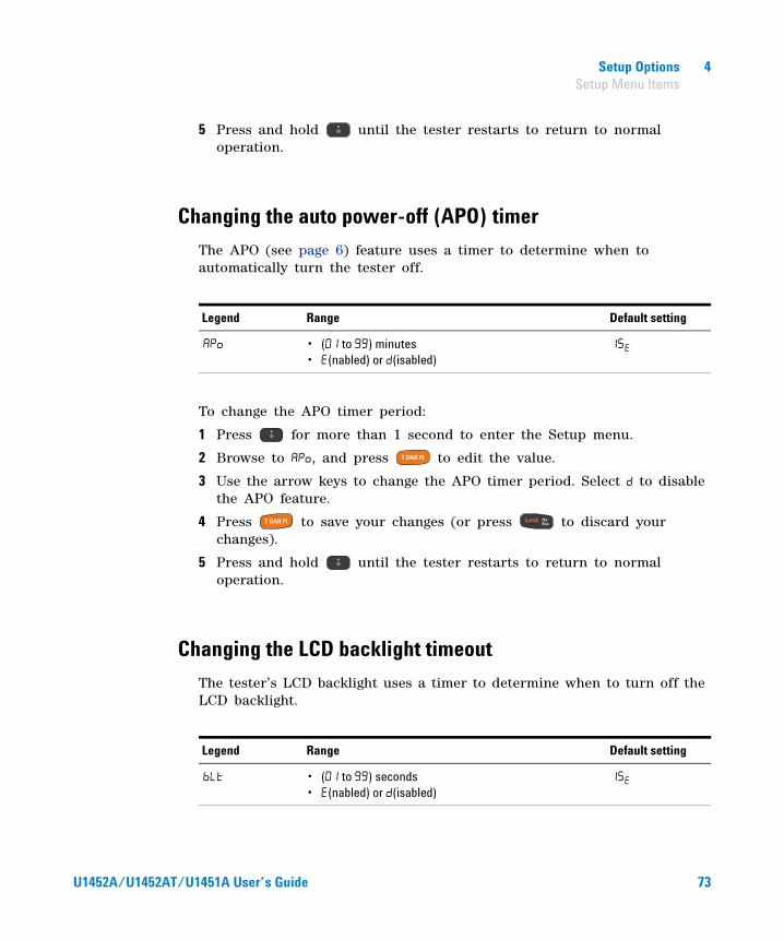
Setup Options 4 Setup Menu Items
5 Press and hold until the tester restarts to return to normal operation.
Changing the auto power-off (APO) timer
The APO (see page 6) feature uses a timer to determine when to automatically turn the tester off.
To change the APO timer period:
1 Press for more than 1 second to enter the Setup menu.
2 Browse to , and press to edit the value.
3 Use the arrow keys to change the APO timer period. Select to disable the APO feature.
4 Press to save your changes (or press to discard your changes).
5 Press and hold until the tester restarts to return to normal operation.
Changing the LCD backlight timeout
The tester’s LCD backlight uses a timer to determine when to turn off the LCD backlight.
Legend Range Default setting
• ( to ) minutes• (nabled) or (isabled)
Legend Range Default setting
• ( to ) seconds• (nabled) or (isabled)
U1452A/U1452AT/U1451A User’s Guide 73

4 Setup Options Setup Menu Items
To change the LCD backlight timer period:
1 Press for more than 1 second to enter the Setup menu.
2 Browse to , and press to edit the value.
3 Use the arrow keys to change the backlight timer period. Select to disable the backlight timer.
4 Press to save your changes (or press to discard your changes).
5 Press and hold until the tester restarts to return to normal operation.
Changing the continuity alert
This setting is used with continuity tests (see page 48). The tester will beep to alert users to the presence of circuit continuities for short circuits. If tone is selected, the tester will sound different tones according to the bar graph display.
To change the continuity alert:
1 Press for more than 1 second to enter the Setup menu.
2 Browse to ( is shown on the display), and press to edit the value.
3 Use the arrow keys to change the continuity alert.
4 Press to save your changes (or press to discard your changes).
5 Press and hold until the tester restarts to return to normal operation.
Legend Range Default setting
(t) or
74 U1452A/U1452AT/U1451A User’s Guide

Setup Options 4 Setup Menu Items
Disabling the power-on melody
The tester plays a melody or a beep when it is powered on.
To disable the power- on melody:
1 Press for more than 1 second to enter the Setup menu.
2 Browse to , and press to edit the value.
3 Use the arrow keys to change the power- on melody. Select to disable the power- on melody.
4 Press to save your changes (or press to discard your changes).
5 Press and hold until the tester restarts to return to normal operation.
Changing the battery type
If you are using rechargeable batteries to power your tester, change the battery type from to for the tester to accurately reflect the battery capacity indication.
Legend Range Default setting
(dy), , , or
NOTE The option is for Agilent internal use.
Legend Range Default setting
(mary) or (ondary)
U1452A/U1452AT/U1451A User’s Guide 75

4 Setup Options Setup Menu Items
To change the battery type:
1 Press for more than 1 second to enter the Setup menu.
2 Browse to , and press to edit the value.
3 Use the arrow keys to change the battery type.
4 Press to save your changes (or press to discard your changes).
5 Press and hold until the tester restarts to return to normal operation.
Resetting the tester’s Setup options
The tester’s Setup options can be reset to its default values through the Setup menu.
1 Press for more than 1 second to enter the Setup menu.
2 Browse to , and press to edit the value.
3 Use the arrow keys to select .
4 Press and hold for more than 1 second to perform the reset. The tester will beep once and return to the first Setup menu page. Or, alternatively press to discard your changes.
Changing the display count
Use these settings to change the display count for the following measurements/tests. The low resolution count is a tenth of the original display count. As an example, if the original display count is 6000 counts, then the low resolution display count is 600 counts.
Legend Range Default setting
or
76 U1452A/U1452AT/U1451A User’s Guide

Setup Options 4 Setup Menu Items
To change the display count:
1 Press for more than 1 second to enter the Setup menu.
2 Browse to , and press to edit the value.
3 Use the arrow keys to change the display count.
4 Press to save your changes (or press to discard your changes).
5 Press and hold until the tester restarts to return to normal operation.
Changing the cable length unit
This setting is used with capacitance measurements (see page 50). Change the unit (Meter or Feet) of the cable length display.
To change the cable length unit:
1 Press for more than 1 second to enter the Setup menu.
2 Browse to , and press to edit the value.
3 Use the arrow keys to change the cable length unit.
Legend Range Default setting
(gh) or (w)
NOTE • Voltage and capacitance measurements are fixed at 6000 counts.
• DAR and PI tests are fixed at 9999 counts.
Legend Range Default setting
(r) or
U1452A/U1452AT/U1451A User’s Guide 77

4 Setup Options Setup Menu Items
4 Press to save your changes (or press to discard your changes).
5 Press and hold until the tester restarts to return to normal operation.
Changing the cable length scale
This setting is used with capacitance measurements (see page 50). Change the scale from 1 nF to 99 nF per kilometer for capacitance transfers to cable length.
To change the cable length scale:
1 Press for more than 1 second to enter the Setup menu.
2 Browse to , and press to edit the value.
3 Use the arrow keys to change the cable length scale.
4 Press to save your changes (or press to discard your changes).
5 Press and hold until the tester restarts to return to normal operation.
Changing the alert indicators
The tester’s audible and visual alerts users to the presence of circuit continuities (see page 48) and values exceeding the Limit values set (see page 48).
Legend Range Default setting
( to ) nF
Legend Range Default setting
., ., ., or . .
78 U1452A/U1452AT/U1451A User’s Guide
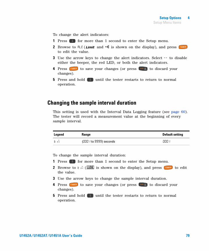
Setup Options 4 Setup Menu Items
To change the alert indicators:
1 Press for more than 1 second to enter the Setup menu.
2 Browse to ( and is shown on the display), and press to edit the value.
3 Use the arrow keys to change the alert indicators. Select to disable either the beeper, the red LED, or both the alert indicators.
4 Press to save your changes (or press to discard your changes).
5 Press and hold until the tester restarts to return to normal operation.
Changing the sample interval duration
This setting is used with the Interval Data Logging feature (see page 60). The tester will record a measurement value at the beginning of every sample interval.
To change the sample interval duration:
1 Press for more than 1 second to enter the Setup menu.
2 Browse to ( is shown on the display), and press to edit the value.
3 Use the arrow keys to change the sample interval duration.
4 Press to save your changes (or press to discard your changes).
5 Press and hold until the tester restarts to return to normal operation.
Legend Range Default setting
( to ) seconds
U1452A/U1452AT/U1451A User’s Guide 79

4 Setup Options Setup Menu Items
Changing the recording option
This setting is used with the Data Logging feature (see page 59). There are three available recording options for the Data Logging feature.
• : Manual log
• : Interval log
• : Event log
To change the recording option:
1 Press for more than 1 second to enter the Setup menu.
2 Browse to ( is shown on the display), and press to edit the value.
3 Use the arrow keys to change the recording option.
4 Press to save your changes (or press to discard your changes).
5 Press and hold until the tester restarts to return to normal operation.
Changing the IR and EBR test period
This setting is used with insulation resistance tests (see page 38) or earth- bond resistance measurements (see page 38). The tester performs the test over the timed period defined in this setting.
Legend Range Default setting
, , or
Legend Range Default setting
(. to .) mm:ss .
80 U1452A/U1452AT/U1451A User’s Guide
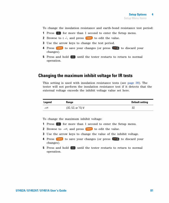
Setup Options 4 Setup Menu Items
To change the insulation resistance and earth- bond resistance test period:
1 Press for more than 1 second to enter the Setup menu.
2 Browse to , and press to edit the value.
3 Use the arrow keys to change the test period.
4 Press to save your changes (or press to discard your changes).
5 Press and hold until the tester restarts to return to normal operation.
Changing the maximum inhibit voltage for IR tests
This setting is used with insulation resistance tests (see page 38). The tester will not perform the insulation resistance test if it detects that the external voltage exceeds the inhibit voltage value set here.
To change the maximum inhibit voltage:
1 Press for more than 1 second to enter the Setup menu.
2 Browse to , and press to edit the value.
3 Use the arrow keys to change the value of the inhibit voltage.
4 Press to save your changes (or press to discard your changes).
5 Press and hold until the tester restarts to return to normal operation.
Legend Range Default setting
(, , or ) V
U1452A/U1452AT/U1451A User’s Guide 81
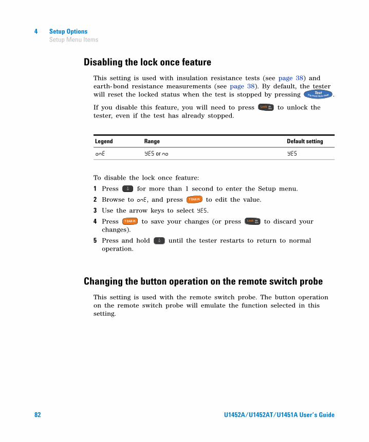
4 Setup Options Setup Menu Items
Disabling the lock once feature
This setting is used with insulation resistance tests (see page 38) and earth- bond resistance measurements (see page 38). By default, the tester will reset the locked status when the test is stopped by pressing .
If you disable this feature, you will need to press to unlock the tester, even if the test has already stopped.
To disable the lock once feature:
1 Press for more than 1 second to enter the Setup menu.
2 Browse to , and press to edit the value.
3 Use the arrow keys to select .
4 Press to save your changes (or press to discard your changes).
5 Press and hold until the tester restarts to return to normal operation.
Changing the button operation on the remote switch probe
This setting is used with the remote switch probe. The button operation on the remote switch probe will emulate the function selected in this setting.
Legend Range Default setting
or
82 U1452A/U1452AT/U1451A User’s Guide

Setup Options 4 Setup Menu Items
To change the button operation on the remote switch probe:
1 Press for more than 1 second to enter the Setup menu.
2 Browse to , and press to edit the value.
3 Use the arrow keys to change the function of the remote switch probe button. Select to disable the remote switch probe button.
4 Press to save your changes (or press to discard your changes).
5 Press and hold until the tester restarts to return to normal operation.
Changing the Dielectric Absorption Ratio (DAR) for IR tests
This setting is used with insulation resistance tests (see page 38). The tester perform the DAR test using the ratio set here.
To change the DAR ratio:
1 Press for more than 1 second to enter the Setup menu.
2 Browse to ( is shown on the display), and press to edit the value.
Legend Range Default setting
• - • - • - • - • - • - • - • (isable) or (nable)
Legend Range Default setting
(. or .) seconds .
U1452A/U1452AT/U1451A User’s Guide 83
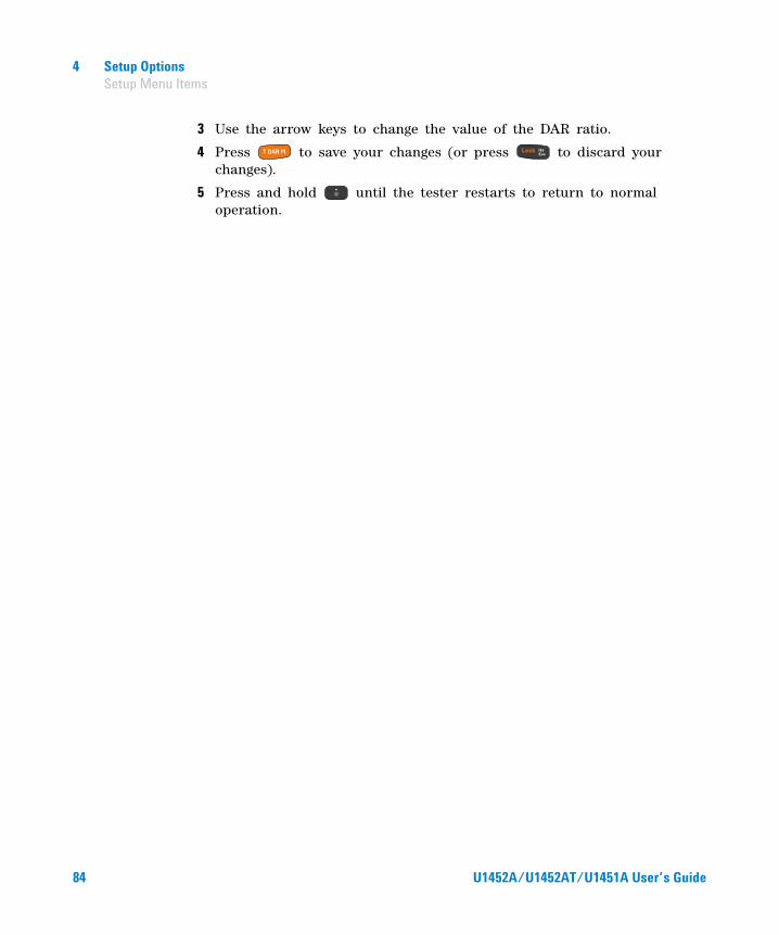
4 Setup Options Setup Menu Items
3 Use the arrow keys to change the value of the DAR ratio.
4 Press to save your changes (or press to discard your changes).
5 Press and hold until the tester restarts to return to normal operation.
84 U1452A/U1452AT/U1451A User’s Guide

U1452A/U1452AT/U1451A Insulation TesterUser’s Guide
5Characteristics and Specifications
Product Characteristics 86
Specification Considerations 88
Measurement Category 88
Electrical Specifications 89DC specifications 89AC specifications 91Capacitance specifications 92Frequency specifications 93Sensitivity for voltage measurements 94Insulation resistance specifications 95Earth-bond resistance specifications 97EN61557 specifications 97Display update rate (approximate) 99
This chapter lists the characteristics, considerations, and specifications of the U1452A/U1452AT/U1451A tester.
85Agilent Technologies

5 Characteristics and Specifications Product Characteristics
Product Characteristics
POWER SUPPLY
Battery type:
• 4 × 1.5 V AA Alkaline batteries (ANSI/NEDA 15A or IEC LR6)• 4 × 1.5 V AA Zinc Chloride batteries (ANSI/NEDA 15D or IEC R6)Battery life:
• 270 hours typical, based on new alkaline batteries for DC voltage measurement at room temperature.
• Insulation Resistance (IR) test: 1000 times of standard test with new alkaline batteries at room temperature. The standard test is 1000 V into 1 MΩ with a cycling of 5 seconds ON and 25 or 55 seconds OFF without backlight.
• Earth-Bond Resistance (EBR) test: 2800 or 2500 times of standard test with new alkaline batteries at room temperature. The standard test is 1 Ω with a cycling of 5 seconds ON and 25 or 55 seconds OFF without backlight.
• Low battery indicator will flash when the battery voltage drops below • For normal operation: 3.4 V (approximately)• For IR and EBR operation: 4.7 V (approximately)
POWER CONSUMPTION
2.7 VA maximum (with backlight)
FUSE
10 × 35 mm 30 kA fast-acting fuse
DISPLAY
Liquid Crystal Display (LCD), 4 digits with maximum reading of 6600 counts
OPERATING ENVIRONMENT
Refer to “Environmental Conditions” on page VI
STORAGE COMPLIANCE
Refer to “Environmental Conditions” on page VI
SAFETY AND EMC COMPLIANCE
Refer to “Environmental Conditions” on page VI
SURGE PROTECTION
8 kV peak per IEC1010.1-92 (IEC1010-1)
MEASUREMENT CATEGORY
CAT III 1000 V/CAT IV 600 V
86 U1452A/U1452AT/U1451A User’s Guide
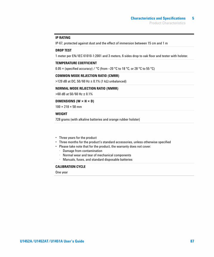
Characteristics and Specifications 5 Product Characteristics
IP RATING
IP-67, protected against dust and the effect of immersion between 15 cm and 1 m
DROP TEST
1 meter per EN/IEC 61010-1:2001 and 3 meters, 6 sides drop to oak floor and tester with holster.
TEMPERATURE COEFFICIENT
0.05 × (specified accuracy) / °C (from –20 °C to 18 °C, or 28 °C to 55 °C)
COMMON MODE REJECTION RATIO (CMRR)
>120 dB at DC, 50/60 Hz ± 0.1% (1 kΩ unbalanced)
NORMAL MODE REJECTION RATIO (NMRR)
>60 dB at 50/60 Hz ± 0.1%
DIMENSIONS (W × H × D)
100 × 218 × 58 mm
WEIGHT
728 grams (with alkaline batteries and orange rubber holster)
• Three years for the product• Three months for the product’s standard accessories, unless otherwise specified• Please take note that for the product, the warranty does not cover:
• Damage from contamination• Normal wear and tear of mechanical components• Manuals, fuses, and standard disposable batteries
CALIBRATION CYCLE
One year
U1452A/U1452AT/U1451A User’s Guide 87

5 Characteristics and Specifications Specification Considerations
Specification Considerations
• Accuracy is given as ± (% of reading + counts of least significant digit) at 23 °C ± 5 °C, with relative humidity less than 80% RH.
• The AC measurement is calibrated for sine waves only.
Measurement Category
The Agilent U1452A/U1452AT/U1451A tester has a safety rating of CAT III, 1000 V and CAT IV, 600 V.
Measurement CAT I are for measurements performed on circuits not directly connected to the AC mains. Examples are measurements on circuits not derived from the AC mains and specially protected (internal) mains-derived circuits.
Measurement CAT II are measurements performed on circuits directly connected to a low-voltage installation. Examples are measurements on household appliances, portable tools, and similar equipment.
Measurement CAT III are measurements performed in the building installation. Examples are measurements on distribution boards, circuit- breakers, wiring, including cables, bus-bars, junction boxes, switches, socket outlets in the fixed installation, and equipment for industrial use, and some other equipment including stationary motors with permanent connection to the fixed installation.
Measurement CAT IV are measurements performed at the source of the low-voltage installation. Examples are electricity meters and measurements on primary over current protection devices and ripple control units.
88 U1452A/U1452AT/U1451A User’s Guide
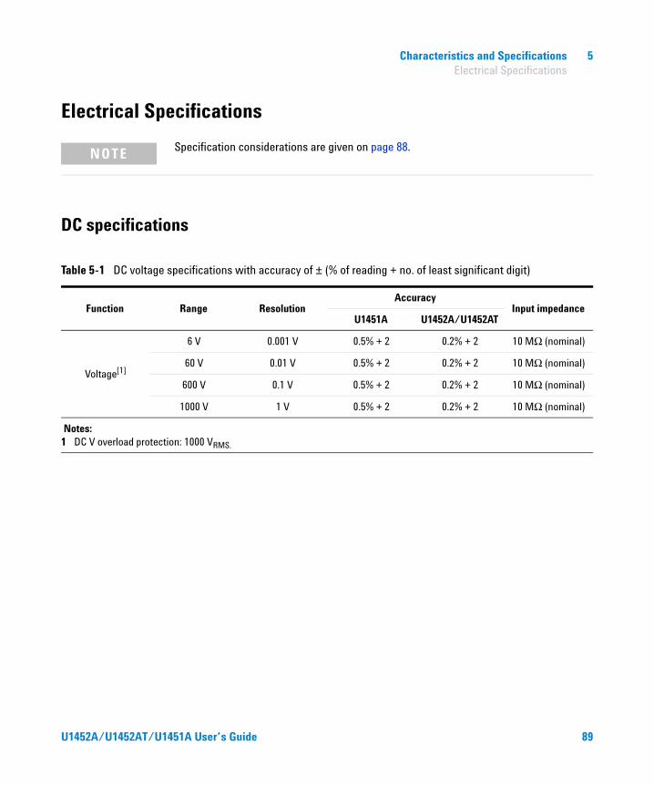
Characteristics and Specifications 5 Electrical Specifications
Electrical Specifications
DC specifications
NOTE Specification considerations are given on page 88.
Table 5-1 DC voltage specifications with accuracy of ± (% of reading + no. of least significant digit)
Function Range ResolutionAccuracy
Input impedanceU1451A U1452A/U1452AT
Voltage[1]
6 V 0.001 V 0.5% + 2 0.2% + 2 10 MΩ (nominal)
60 V 0.01 V 0.5% + 2 0.2% + 2 10 MΩ (nominal)
600 V 0.1 V 0.5% + 2 0.2% + 2 10 MΩ (nominal)
1000 V 1 V 0.5% + 2 0.2% + 2 10 MΩ (nominal)
Notes:1 DC V overload protection: 1000 VRMS.
U1452A/U1452AT/U1451A User’s Guide 89
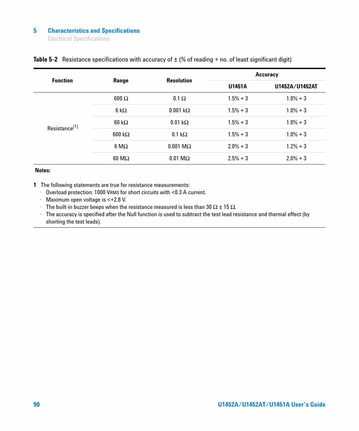
5 Characteristics and Specifications Electrical Specifications
Table 5-2 Resistance specifications with accuracy of ± (% of reading + no. of least significant digit)
Function Range ResolutionAccuracy
U1451A U1452A/U1452AT
Resistance[1]
600 Ω 0.1 Ω 1.5% + 3 1.0% + 3
6 kΩ 0.001 kΩ 1.5% + 3 1.0% + 3
60 kΩ 0.01 kΩ 1.5% + 3 1.0% + 3
600 kΩ 0.1 kΩ 1.5% + 3 1.0% + 3
6 MΩ 0.001 MΩ 2.0% + 3 1.2% + 3
60 MΩ 0.01 MΩ 2.5% + 3 2.0% + 3
Notes:
1 The following statements are true for resistance measurements:• Overload protection: 1000 VRMS for short circuits with <0.3 A current.• Maximum open voltage is <+2.8 V.• The built-in buzzer beeps when the resistance measured is less than 30 Ω ± 15 Ω.• The accuracy is specified after the Null function is used to subtract the test lead resistance and thermal effect (by
shorting the test leads).
90 U1452A/U1452AT/U1451A User’s Guide

Characteristics and Specifications 5 Electrical Specifications
AC specifications
Table 5-3 AC voltage specifications with accuracy of ± (% of reading + no. of least significant digit)
Function Range ResolutionAccuracy
45 Hz to 400 Hz
Voltage[1]
6 V 0.001 V 2.0% + 3
60 V 0.01 V 2.0% + 3
600 V 0.1 V 2.0% + 3
1000 V 1 V 2.0% + 3
Notes:
1 The following statements are true for resistance measurements:• AC V overload protection: 1000 VRMS.• AC V input impedance: 10 MΩ in parallel with <100 pF (nominal).• The input signal is lower than the product of 1,000,000 V×Hz.
U1452A/U1452AT/U1451A User’s Guide 91
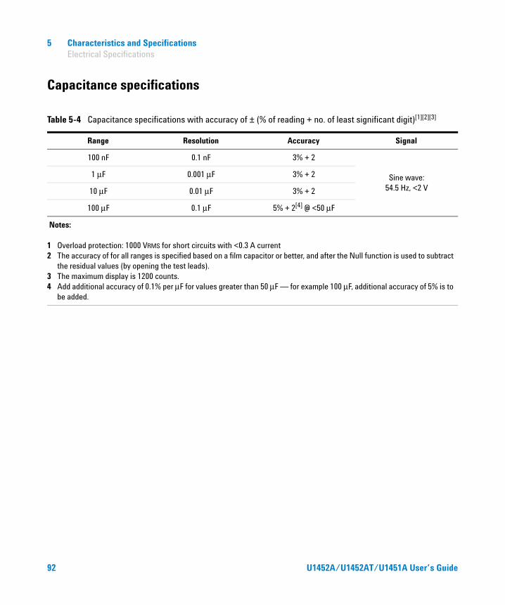
5 Characteristics and Specifications Electrical Specifications
Capacitance specifications
Table 5-4 Capacitance specifications with accuracy of ± (% of reading + no. of least significant digit)[1][2][3]
Range Resolution Accuracy Signal
100 nF 0.1 nF 3% + 2
Sine wave: 54.5 Hz, <2 V
1 μF 0.001 μF 3% + 2
10 μF 0.01 μF 3% + 2
100 μF 0.1 μF 5% + 2[4] @ <50 μF
Notes:
1 Overload protection: 1000 VRMS for short circuits with <0.3 A current2 The accuracy of for all ranges is specified based on a film capacitor or better, and after the Null function is used to subtract
the residual values (by opening the test leads).3 The maximum display is 1200 counts.4 Add additional accuracy of 0.1% per μF for values greater than 50 μF — for example 100 μF, additional accuracy of 5% is to
be added.
92 U1452A/U1452AT/U1451A User’s Guide
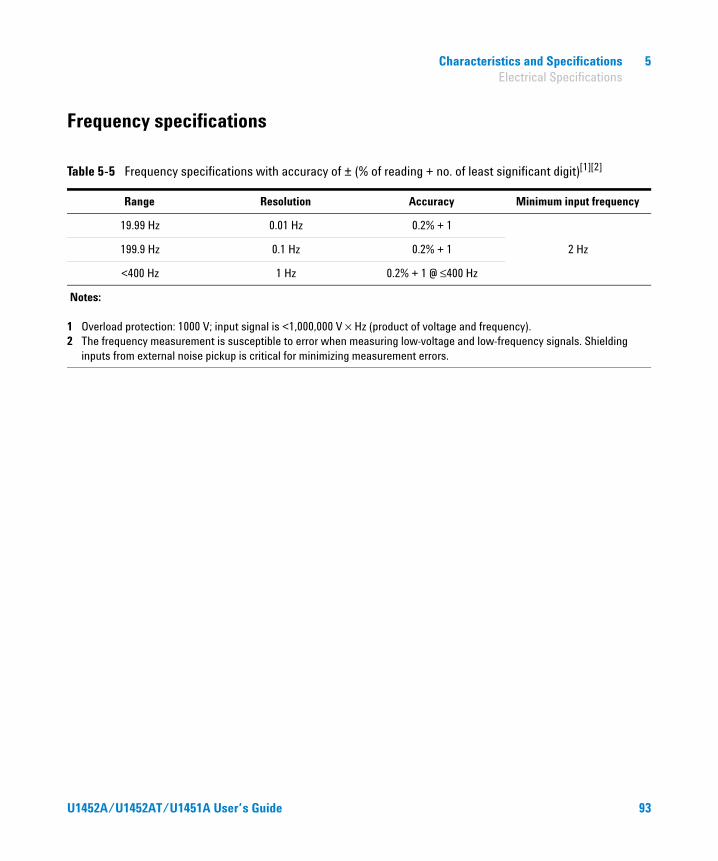
Characteristics and Specifications 5 Electrical Specifications
Frequency specifications
Table 5-5 Frequency specifications with accuracy of ± (% of reading + no. of least significant digit)[1][2]
Range Resolution Accuracy Minimum input frequency
19.99 Hz 0.01 Hz 0.2% + 1
2 Hz199.9 Hz 0.1 Hz 0.2% + 1
<400 Hz 1 Hz 0.2% + 1 @ ≤400 Hz
Notes:
1 Overload protection: 1000 V; input signal is <1,000,000 V × Hz (product of voltage and frequency).2 The frequency measurement is susceptible to error when measuring low-voltage and low-frequency signals. Shielding
inputs from external noise pickup is critical for minimizing measurement errors.
U1452A/U1452AT/U1451A User’s Guide 93
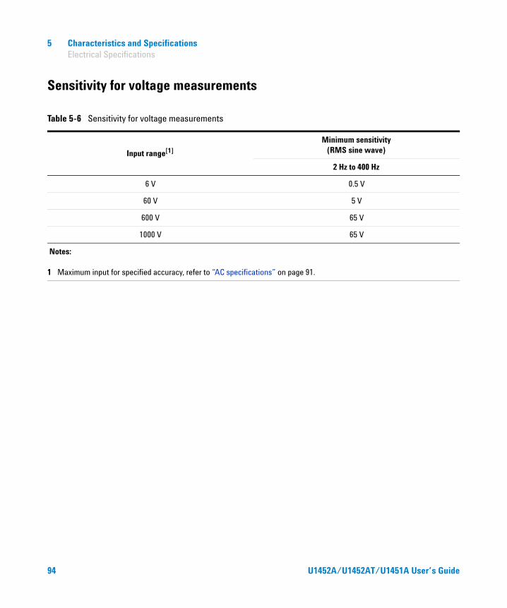
5 Characteristics and Specifications Electrical Specifications
Sensitivity for voltage measurements
Table 5-6 Sensitivity for voltage measurements
Input range[1]
Minimum sensitivity (RMS sine wave)
2 Hz to 400 Hz
6 V 0.5 V
60 V 5 V
600 V 65 V
1000 V 65 V
Notes:
1 Maximum input for specified accuracy, refer to “AC specifications” on page 91.
94 U1452A/U1452AT/U1451A User’s Guide
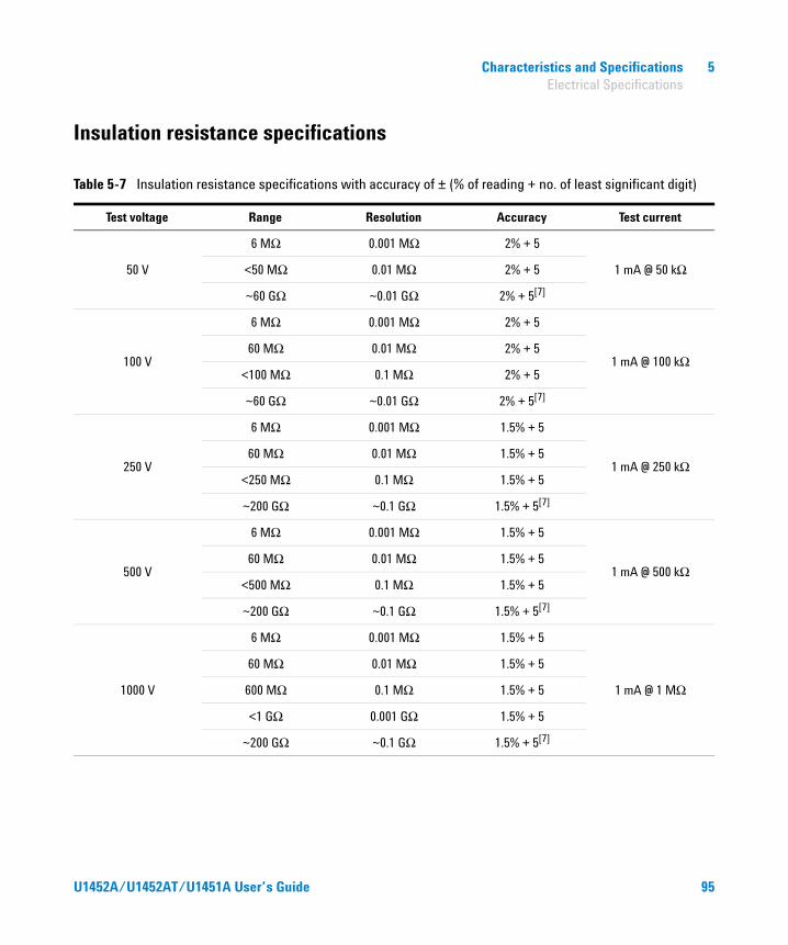
Characteristics and Specifications 5 Electrical Specifications
Insulation resistance specifications
Table 5-7 Insulation resistance specifications with accuracy of ± (% of reading + no. of least significant digit)
Test voltage Range Resolution Accuracy Test current
50 V
6 MΩ 0.001 MΩ 2% + 5
1 mA @ 50 kΩ<50 MΩ 0.01 MΩ 2% + 5
~60 GΩ ~0.01 GΩ 2% + 5[7]
100 V
6 MΩ 0.001 MΩ 2% + 5
1 mA @ 100 kΩ60 MΩ 0.01 MΩ 2% + 5
<100 MΩ 0.1 MΩ 2% + 5
~60 GΩ ~0.01 GΩ 2% + 5[7]
250 V
6 MΩ 0.001 MΩ 1.5% + 5
1 mA @ 250 kΩ60 MΩ 0.01 MΩ 1.5% + 5
<250 MΩ 0.1 MΩ 1.5% + 5
~200 GΩ ~0.1 GΩ 1.5% + 5[7]
500 V
6 MΩ 0.001 MΩ 1.5% + 5
1 mA @ 500 kΩ60 MΩ 0.01 MΩ 1.5% + 5
<500 MΩ 0.1 MΩ 1.5% + 5
~200 GΩ ~0.1 GΩ 1.5% + 5[7]
1000 V
6 MΩ 0.001 MΩ 1.5% + 5
1 mA @ 1 MΩ
60 MΩ 0.01 MΩ 1.5% + 5
600 MΩ 0.1 MΩ 1.5% + 5
<1 GΩ 0.001 GΩ 1.5% + 5
~200 GΩ ~0.1 GΩ 1.5% + 5[7]
U1452A/U1452AT/U1451A User’s Guide 95
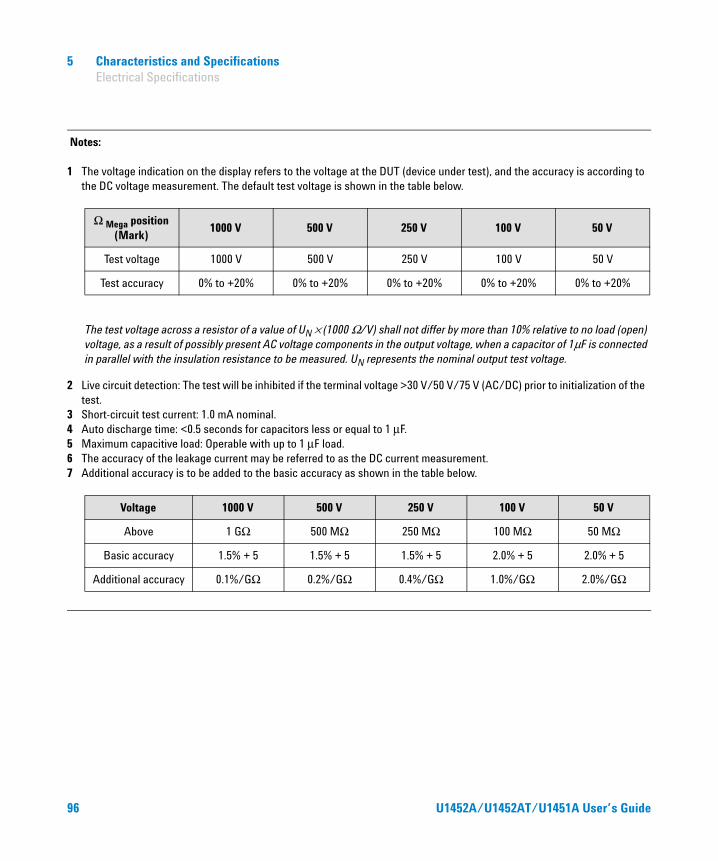
5 Characteristics and Specifications Electrical Specifications
Notes:
1 The voltage indication on the display refers to the voltage at the DUT (device under test), and the accuracy is according to the DC voltage measurement. The default test voltage is shown in the table below.
2 Live circuit detection: The test will be inhibited if the terminal voltage >30 V/50 V/75 V (AC/DC) prior to initialization of the test.
3 Short-circuit test current: 1.0 mA nominal.4 Auto discharge time: <0.5 seconds for capacitors less or equal to 1 μF.5 Maximum capacitive load: Operable with up to 1 μF load.6 The accuracy of the leakage current may be referred to as the DC current measurement.7 Additional accuracy is to be added to the basic accuracy as shown in the table below.
The test voltage across a resistor of a value of UN × (1000 Ω/V) shall not differ by more than 10% relative to no load (open) voltage, as a result of possibly present AC voltage components in the output voltage, when a capacitor of 1μF is connected in parallel with the insulation resistance to be measured. UN represents the nominal output test voltage.
Ω Mega position (Mark)
1000 V 500 V 250 V 100 V 50 V
Test voltage 1000 V 500 V 250 V 100 V 50 V
Test accuracy 0% to +20% 0% to +20% 0% to +20% 0% to +20% 0% to +20%
Voltage 1000 V 500 V 250 V 100 V 50 V
Above 1 GΩ 500 MΩ 250 MΩ 100 MΩ 50 MΩ
Basic accuracy 1.5% + 5 1.5% + 5 1.5% + 5 2.0% + 5 2.0% + 5
Additional accuracy 0.1%/GΩ 0.2%/GΩ 0.4%/GΩ 1.0%/GΩ 2.0%/GΩ
96 U1452A/U1452AT/U1451A User’s Guide

Characteristics and Specifications 5 Electrical Specifications
Earth-bond resistance specifications
EN61557 specifications
The following specifications are a requirement for European labeling.
Table 5-8 Earth-bond resistance specifications with accuracy of ± (% of reading + no. of least significant
digit)[1][2]
Range ResolutionAccuracy
Open circuit voltageU1451A U1452A/U1452AT
60 Ω 0.01 Ω 1.5% + 3 1.0% + 3
>4 V and <7 V600 Ω 0.1 Ω 1.5% + 3 1.0% + 3
6 kΩ 0.001 kΩ 1.5% + 3 1.0% + 3
60 kΩ 0.01 kΩ 1.5% + 3 1.0% + 3
Notes:
1 The following statements are true for earth-bond resistance tests:• Overload protection: <2 V and 0.44 A/1000 V; 10 × 35 mm 30 kA fast-acting fuse• Short circuit current: >200.0 mA as resistance < or = 2 Ω
2 The accuracy is specified after the Null function is used to subtract the test lead resistance and thermal effect (by shorting the test leads).
MeasurementIntrinsic uncertainty
Operating uncertainty[1]
U1451A U1452A/U1452AT
Voltage ± (0.5% + 2) ± (0.2% + 2) 30%
Notes:
1 The maximum resistance to meet the standard of EN61557-1, 5.2.4, which indicates the maximum amount allowed as less than 30%.
U1452A/U1452AT/U1451A User’s Guide 97
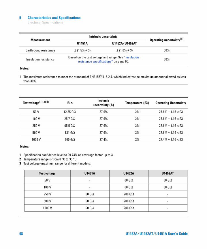
5 Characteristics and Specifications Electrical Specifications
Earth-bond resistance ± (1.5% + 3) ± (1.0% + 3) 30%
Insulation resistanceBased on the test voltage and range. See “Insulation
resistance specifications” on page 95.30%
MeasurementIntrinsic uncertainty
Operating uncertainty[1]
U1451A U1452A/U1452AT
Notes:
1 The maximum resistance to meet the standard of EN61557-1, 5.2.4, which indicates the maximum amount allowed as less than 30%.
Test voltage[1][2][3] IR <Intrinsic
uncertainty (A)Temperature (E3) Operating Uncertainty
50 V 12.85 GΩ 27.6% 2% 27.6% + 1.15 × E3
100 V 25.7 GΩ 27.6% 2% 27.6% + 1.15 × E3
250 V 65.5 GΩ 27.6% 2% 27.6% + 1.15 × E3
500 V 131 GΩ 27.6% 2% 27.6% + 1.15 × E3
1000 V 260 GΩ 27.4% 2% 27.4% + 1.15 × E3
Notes:
1 Specification confidence level to 99.73% as coverage factor up to 3.2 Temperature range is from 0 °C to 35 °C.3 Test voltage/maximum range for different models:
Test voltage U1451A U1452A U1452AT
50 V - 60 GΩ 60 GΩ
100 V - 60 GΩ 60 GΩ
250 V 60 GΩ 200 GΩ -
500 V 60 GΩ 200 GΩ -
1000 V 60 GΩ 200 GΩ -
98 U1452A/U1452AT/U1451A User’s Guide

Characteristics and Specifications 5 Electrical Specifications
Display update rate (approximate)
Table 5-9 Display update rate (approximate)
Function Times/Second
AC V 5
DC V 5
Ω 5
Capacitance 5
EBR 5
IR 5
Frequency 1 (>10 Hz)
U1452A/U1452AT/U1451A User’s Guide 99
5 Characteristics and Specifications Electrical Specifications
THIS PAGE HAS BEEN INTENTIONALLY LEFT BLANK.
100 U1452A/U1452AT/U1451A User’s Guide

Agilent Technologies