Agilent N7600A Signal Studio for 3GPP W-CDMA with...
12
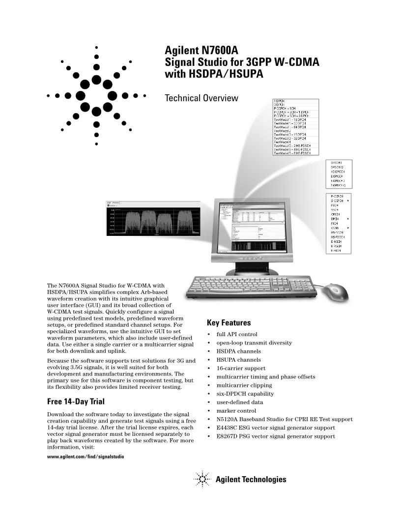
Agilent N7600A Signal Studio for 3GPP W-CDMA with HSDPA/HSUPA Technical Overview The N7600A Signal Studio for W-CDMA with HSDPA/HSUPA simplifies complex Arb-based waveform creation with its intuitive graphical user interface (GUI) and its broad collection of W-CDMA test signals. Quickly configure a signal using predefined test models, predefined waveform setups, or predefined standard channel setups. For specialized waveforms, use the intuitive GUI to set waveform parameters, which also include user-defined data. Use either a single carrier or a multicarrier signal for both downlink and uplink. Because the software supports test solutions for 3G and evolving 3.5G signals, it is well suited for both development and manufacturing environments. The primary use for this software is component testing, but its flexibility also provides limited receiver testing. Free 14-Day Trial Download the software today to investigate the signal creation capability and generate test signals using a free 14-day trial license. After the trial license expires, each vector signal generator must be licensed separately to play back waveforms created by the software. For more information, visit: www.agilent.com/find/signalstudio Key Features • full API control • open-loop transmit diversity • HSDPA channels • HSUPA channels • 16-carrier support • multicarrier timing and phase offsets • multicarrier clipping • six-DPDCH capability • user-defined data • marker control • N5120A Baseband Studio for CPRI RE Test support • E4438C ESG vector signal generator support • E8267D PSG vector signal generator support
Transcript of Agilent N7600A Signal Studio for 3GPP W-CDMA with...
Agilent N7600ASignal Studio for 3GPP W-CDMA with HSDPA/HSUPA
Technical Overview
The N7600A Signal Studio for W-CDMA with HSDPA/HSUPA simplifies complex Arb-based waveform creation with its intuitive graphical user interface (GUI) and its broad collection of W-CDMA test signals. Quickly configure a signal using predefined test models, predefined waveform setups, or predefined standard channel setups. For specialized waveforms, use the intuitive GUI to set waveform parameters, which also include user-defined data. Use either a single carrier or a multicarrier signal for both downlink and uplink.
Because the software supports test solutions for 3G and evolving 3.5G signals, it is well suited for both development and manufacturing environments. The primary use for this software is component testing, but its flexibility also provides limited receiver testing.
Free 14-Day Trial
Download the software today to investigate the signal creation capability and generate test signals using a free 14-day trial license. After the trial license expires, each vector signal generator must be licensed separately to play back waveforms created by the software. For more information, visit:
www.agilent.com/find/signalstudio
Key Features• full API control• open-loop transmit diversity• HSDPA channels
• HSUPA channels• 16-carrier support• multicarrier timing and phase offsets
• multicarrier clipping• six-DPDCH capability• user-defined data
• marker control• N5120A Baseband Studio for CPRI RE Test support• E4438C ESG vector signal generator support
• E8267D PSG vector signal generator support

Introduction
Configure multicarrier downlink and uplink 3GPP W-CDMA test signals with the proper stress level to exercise components, including combiners, filters, and amplifiers. Use these signals for base station and mobile tests ranging from the component level to the system level; however, they are primarily intended for the component test industry. To simplify signal setup, the software provides preconfigured channel setups.
Feature DescriptionSupported method Frequency Division Duplex [FDD] 3GPP
W-CDMA, HSDPA, and HSUPA
Supported version 3GPP Release 6, version 9-2005
Transmit diversity Open loop antenna 1 and 2
Coding level Supports physical layer coding (spreading and scrambling)
Waveform length 10 ms continuously repeated
Filters Standards-based
Baseband clipping Pre- and Post-FIR
Data types PN9, random, paging indicator, user-defined
Standards-based setups Test models 1 through 5
Number of carriers 16
Number of channels per carrier
512
Downlink channels CPICH, PSCH, SSCH,P-CCPCH, S-CCPCH,PICH,DPCH, OCNS, HS-SCCH,HS-PDSCH, E-AGCH, E-RGCH, E-HICH
Uplink channels DPCCH, DPDCH, HS-DPCCH, E-DPCCH, E-DPDCH
Downlink Uplink
Figure 1 Downlink and uplink preconfigured channel setups.
2
Waveform File Exporting
The software lets you export encrypted waveform files to your PC. After exporting the file, you can download the file to any signal generator licensed for the N7600A software.
CPRI testing
Build waveforms for CPRI RE test solutions. When properly licensed, the N5120A Baseband Studio for CPRI RE Test uses theN7600A’s exported waveform file to create signals. To use the file with the N5120A software, simply create an association between the N5120A software and the exported N7600A waveform file.

Waveform Playback
The N7600A software takes advantage of the ESG and PSG baseband generators’ 80-MHz I/Q bandwidth by allowing for carrier offsets of ±37.5 MHz. This offset limit fully accommodates 16 carriers.
ESGs and PSGs configured with Option 602 (baseband generator with 64 megasamples of RAM) accommodate large waveform files for playback.
The software downloads the waveform into the signal generator’s volatile memory. After downloading, the signal generator sends the waveform samples through a reconstruction filter and then an I/Q modulator.
Because these signals are primarily intended for component test, the software does not implement full channel coding. Instead, when the signal generator plays the waveform, it produces partially coded signals that are statistically equivalent to fully coded signals. This means that the signal stresses amplifiers and other components exactly the same as if using a fully coded signal.
Figure 2 This graphic shows a ten-carrier setup that uses the signal generator’s 80 MHz I/Q bandwidth (±37.5 MHz frequency offset range).
3

Feature Summary
Multicarrier capability
Stress active components. Configure up to 16 carriers, with each carrier having the same or a unique channel configuration, frequency offset, and power offset.
To ensure that a device under test experiences actual operating conditions, the Signal Studio for 3GPP W-CDMA with HSDPA/HSUPA provides settings for generating uncorrelated signals, which are important for creating realistic crest factors. Make relative carrier adjustments using the following settings:
• timing offset• starting phase• scramble code• clipping level
Channel editing
Easily modify channel configurations.
• Modify the W-CDMA downlink by changing parameters such as data rate, data pattern, orthogonal variable spreading factor [OVSF] code, power, timing offset, TFCI bits, TFCI power, TPC bits, TPC power, pilot bits, pilot power, scramble code, scramble type, scramble offset, and the E-RGCH and E-HICH signature sequence patterns.
• Modify the W-CDMA uplink by changing parameters such as data rate, data pattern, OVSF code, power, TFCI bits, TPC bits, FBI bits, ACK/NACK, and CQI.
4
Preconfigured channel setups
Quickly generate 3GPP standard signals. Test models 1 through 5 are predefined for testing transmitter components.
• test model 1 – ACLR, spurious emissions and intermodulation
• test model 2 – output power dynamics
• test model 3 – peak code domain power• test model 4 – EVM measurements• test model 5 – EVM measurements for base stations
supporting HS-PDSCH
Also access other predefined configurations or save and recall custom channel configurations.
Selectable filtering options
Quickly select and configure commonly used filters. Choose a root Nyquist, Nyquist, Gaussian, or rectangular filter. Configure the filter response using the alpha and BbT values.
Flexible baseband clipping
Reduce signal stress on power amplifiers. Clip the peak-to-average power of signals before or after baseband FIR filtering. Clip the signal before filtering to smooth any discontinuities in the resulting signal that can generate distortion. Clip the signal after FIR filtering to simulate a base station that operates in this mode.
Code Domain power, CCDF curve, and waveform graphs
Quickly check signal statistics.
Save time by using the provided graphs to check a waveform prior to downloading into a signal generator or exporting the waveform file to your PC.
• Use the code domain power graph to visually check the channel configuration and the relative channel power.
• Use the CCDF curve to view the peak-to-average ratio or the power statistics of the waveform as compared to a Gaussian reference, or a previous signal’s plot.
• Use the waveform graph to check the composite waveform’s spectrum, power, and I/Q signal.

Feature Summary (Cont’d)
Transmit diversity
Evaluate receiver performance with open loop transmit diversity. Transmit diversity is a technique used to counter the effects of fading by transmitting an altered version of the W-CDMA signal through a second antenna. The multicarrier feature of the software enables you to configure both antennas on one waveform (2 carriers), or any combination of antennas (one and two) using up to 16 carriers in a single waveform. The primary and secondary synchronization channels employ transmit switched time diversity (TSTD); most of the other channels use space time transmit diversity (STTD).
HSDPA and HSUPA
Test components to 3.5G standards. Set the signal for higher data rates along with HARQ and CQI features. The provided E-HICH and E-RGCH incorporate signature sequence selections that determine the supported signature hopping patterns. Use the E-DPDCH and E-DPCCH to simulate data and feedback information to base station components.
API control
Remotely set all software parameters. Included with the software is a full API. Use the API to set parameters either programmatically or by using an API graphical user interface.
System configuration wizard
Choose the interface connection for your equipment. When you run the software, the system configuration wizard provides simple choices to quickly configure the hardware you wish to use. You also have the choice of selecting simulated hardware, which enables you to configure the software without actually connecting hardware to your PC.
You can change hardware configurations at any time, and as often as you wish. You can also save hardware setups for future use, and recall previously saved setups.
Downlink and Uplink FeaturesMulticarrier
Number of carriers
Frequency offset [per carrier]Offset resolutionCarrier power [per carrier]Clipping
Primary scramble code
Timing offset
Initial phase
Up to 16 within an 80 MHz bandwidth [user defined, individually configurable]Up to ± 37.5 MHz
1 Hz−40 dB to 0 dB-Clip each carrier before or after FIR filtering0 to 511 [applied to each channel in the carrier]0 to 149 in increments of 512 chips [applied to each channel in the carrier]0 to 359 degrees [set the phase for each carrier]
Number of channels Up to 512 per carrier
Coding level Supports physical layer coding
Frame duration 10 ms
Filters
NoneNyquist, root NyquistGaussianRectangle
a = 0 to 1BbT = 0 to 1
I/Q mapping Normal, Invert
Clipping
Clip locationClipping typeClipping range
Pre- or post-FIR filter|I+jQ|10% to 100% [Clip the modulation level to a percentage of full scale. A level of 100% equates to no clipping.]
Markers 4 preconfigured or user definable markers
5

Downlink FeaturesTransmit diversity Open loop
Modulation QPSK and 16QAMa
a16QAM is supported for the HS-PDSCH.
Primary scramble code 0 to 511
Pre-defined channel configurations
Test model 1 with 16, 32, or 64 DPCHTest model 2Test model 3 with 16 or 32 DPCHTest model 4
Test model 5 with 2, 4, or 8 HS-PDSCHa
1 DPCH3 DPCHPCCPCH + SCHPCCPCH + SCH + 1 DPCHPCCPCH + SCH + 3 DPCH
Common Pilot Channel [CPICH]
PowerSpreading codeSymbol rateScramble codeScramble typeScramble offset
−60 dB to 0 dB0 to 255Fixed to 15 ksps0 to 511Standard, left alternate, and right alternate0 to 15
Primary Synchronization Channel [PSCH]
PowerSymbol rate
−60 dB to 0 dBFixed to 15 ksps
Secondary Synchronization Channel [SSCH]
PowerSymbol rateScramble codeScramble typeScramble offset
−60 dB to 0 dBFixed to 15 ksps0 to 511Standard, left alternate, and right alternate0 to 15
6
Primary Common Control Physical Channel [P-CCPCH]
PowerSpreading codeSymbol rateData patternScramble codeScramble typeScramble offset
−60 dB to 0 dB0 to 255Fixed to 15 kspsPN9, random, and user defined0 to 511Standard, left alternate, and right alternate0 to 15
Secondary Common Control Physical Channel [S-CCPCH]
PowerSpreading codeSymbol rateTiming offsetTFCITFCI powerNumber of pilot bitsData patternScramble codeScramble typeScramble offset
−60 dB to 0 dB0 to 25515, 30, 60, 120, 240, 480, 960 ksps0 to 149 [in increments of 256 chips]0 to 1023, or disable TFCI bits in the carrier−20 to 20 dB relative to channel0, 8, or 16PN9, random, and user defined0 to 511Standard, left alternate, and right alternate0 to 15
Page Indication Channel [PICH]
PowerSpreading codeSymbol rateTiming offsetData pattern
Scramble codeScramble typeScramble offset
−60 dB to 0 dB0 to 255Fixed to 15 ksps0 to 149 [increments of 256 chips]Paging indicator [18 bit paging pattern], PN9, random, and user defined0 to 511Standard, left alternate, and right alternate0 to 15
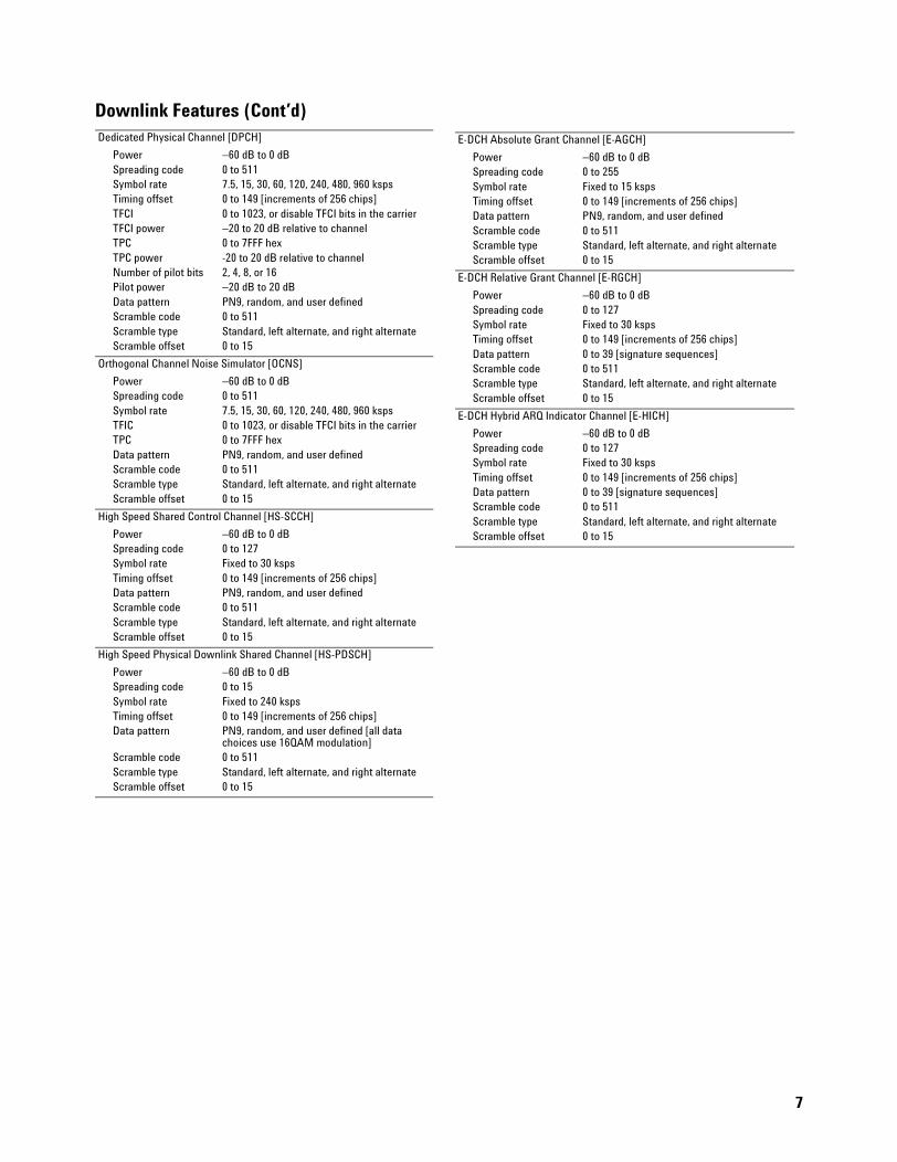
Downlink Features (Cont’d)Dedicated Physical Channel [DPCH]
PowerSpreading codeSymbol rateTiming offsetTFCITFCI powerTPCTPC powerNumber of pilot bitsPilot powerData patternScramble codeScramble typeScramble offset
−60 dB to 0 dB0 to 5117.5, 15, 30, 60, 120, 240, 480, 960 ksps0 to 149 [increments of 256 chips]0 to 1023, or disable TFCI bits in the carrier−20 to 20 dB relative to channel0 to 7FFF hex-20 to 20 dB relative to channel2, 4, 8, or 16−20 dB to 20 dBPN9, random, and user defined0 to 511Standard, left alternate, and right alternate0 to 15
Orthogonal Channel Noise Simulator [OCNS]
PowerSpreading codeSymbol rateTFICTPCData patternScramble codeScramble typeScramble offset
−60 dB to 0 dB0 to 5117.5, 15, 30, 60, 120, 240, 480, 960 ksps0 to 1023, or disable TFCI bits in the carrier0 to 7FFF hexPN9, random, and user defined0 to 511Standard, left alternate, and right alternate0 to 15
High Speed Shared Control Channel [HS-SCCH]
PowerSpreading codeSymbol rateTiming offsetData patternScramble codeScramble typeScramble offset
−60 dB to 0 dB0 to 127Fixed to 30 ksps0 to 149 [increments of 256 chips]PN9, random, and user defined0 to 511Standard, left alternate, and right alternate0 to 15
High Speed Physical Downlink Shared Channel [HS-PDSCH]
PowerSpreading codeSymbol rateTiming offsetData pattern
Scramble codeScramble typeScramble offset
−60 dB to 0 dB0 to 15Fixed to 240 ksps0 to 149 [increments of 256 chips]PN9, random, and user defined [all data choices use 16QAM modulation]0 to 511Standard, left alternate, and right alternate0 to 15
E-DCH Absolute Grant Channel [E-AGCH]
PowerSpreading codeSymbol rateTiming offsetData patternScramble codeScramble typeScramble offset
−60 dB to 0 dB0 to 255Fixed to 15 ksps0 to 149 [increments of 256 chips]PN9, random, and user defined0 to 511Standard, left alternate, and right alternate0 to 15
E-DCH Relative Grant Channel [E-RGCH]
PowerSpreading codeSymbol rateTiming offsetData patternScramble codeScramble typeScramble offset
−60 dB to 0 dB0 to 127Fixed to 30 ksps0 to 149 [increments of 256 chips]0 to 39 [signature sequences]0 to 511Standard, left alternate, and right alternate0 to 15
E-DCH Hybrid ARQ Indicator Channel [E-HICH]
PowerSpreading codeSymbol rateTiming offsetData patternScramble codeScramble typeScramble offset
−60 dB to 0 dB0 to 127Fixed to 30 ksps0 to 149 [increments of 256 chips]0 to 39 [signature sequences]0 to 511Standard, left alternate, and right alternate0 to 15
7
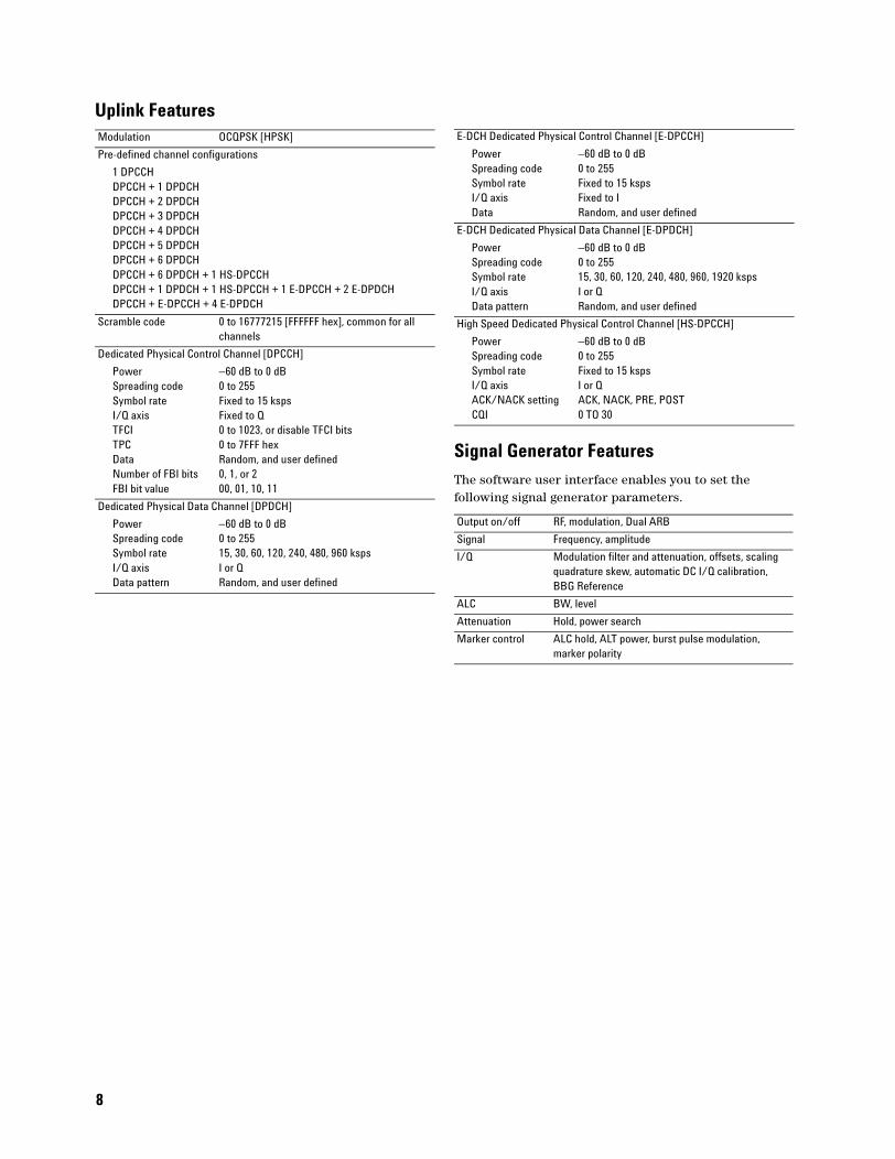
Uplink FeaturesModulation OCQPSK [HPSK]
Pre-defined channel configurations
1 DPCCHDPCCH + 1 DPDCHDPCCH + 2 DPDCH DPCCH + 3 DPDCHDPCCH + 4 DPDCHDPCCH + 5 DPDCHDPCCH + 6 DPDCHDPCCH + 6 DPDCH + 1 HS-DPCCHDPCCH + 1 DPDCH + 1 HS-DPCCH + 1 E-DPCCH + 2 E-DPDCHDPCCH + E-DPCCH + 4 E-DPDCH
Scramble code 0 to 16777215 [FFFFFF hex], common for all channels
Dedicated Physical Control Channel [DPCCH]
PowerSpreading codeSymbol rateI/Q axisTFCITPCDataNumber of FBI bitsFBI bit value
−60 dB to 0 dB0 to 255Fixed to 15 kspsFixed to Q0 to 1023, or disable TFCI bits0 to 7FFF hexRandom, and user defined0, 1, or 200, 01, 10, 11
Dedicated Physical Data Channel [DPDCH]
Power Spreading codeSymbol rateI/Q axisData pattern
−60 dB to 0 dB0 to 25515, 30, 60, 120, 240, 480, 960 kspsI or QRandom, and user defined
8
Signal Generator Features
The software user interface enables you to set the following signal generator parameters.
E-DCH Dedicated Physical Control Channel [E-DPCCH]
PowerSpreading codeSymbol rateI/Q axisData
−60 dB to 0 dB0 to 255Fixed to 15 kspsFixed to IRandom, and user defined
E-DCH Dedicated Physical Data Channel [E-DPDCH]
Power Spreading codeSymbol rateI/Q axisData pattern
−60 dB to 0 dB0 to 25515, 30, 60, 120, 240, 480, 960, 1920 kspsI or QRandom, and user defined
High Speed Dedicated Physical Control Channel [HS-DPCCH]
PowerSpreading codeSymbol rateI/Q axisACK/NACK settingCQI
−60 dB to 0 dB0 to 255Fixed to 15 kspsI or QACK, NACK, PRE, POST0 TO 30
Output on/off RF, modulation, Dual ARB
Signal Frequency, amplitude
I/Q Modulation filter and attenuation, offsets, scaling quadrature skew, automatic DC I/Q calibration, BBG Reference
ALC BW, level
Attenuation Hold, power search
Marker control ALC hold, ALT power, burst pulse modulation, marker polarity

Recommended Configurations for Signal Studio for 3GPP W-CDMA with HSDPA/HSUPA
RF waveform downloads Model/option Description
N7600A-203 Signal Studio for W-CDMA
N7600A-101a
aThe signal generator requires Option 001, 002, 601, or 602.
License E4438C ESG
E4438Cb
bE4438C requires firmware revision C.04.10 or later. Download firmware updates from www.agilent.com/find/esg.
ESG vector signal generator
E4438C-005 6 GB internal hard drive
E4438C-1E5 High-stability time base
E4438C-403 Calibrated noise (AWGN)
E4438C-503 250 kHz to 3 GHz frequency range
E4438C-602c
cEarlier baseband Options 001 and 002 are also supported
Internal baseband generator (64 MSa memory)
Microwave waveform downloads
Other signal generator configurations are available. For details regarding the E4438C ESG and the E8267D PSG option structure, refer to the Configuration Guide listed in the “Related Literature” section.
Model/option Description
N7600A-203 Signal Studio for W-CDMA
N7600A-102a
aThe signal generator requires Option 601 or 602.
License E8267D PSG
E8267Db
bE8267D requires firmware revision C.04.11 or later. Download firmware updates from www.agilent.com/find/psg.
PSG vector signal generator
E8267D-005 6 GB internal hard drive
E8267D-403 Calibrated noise (AWGN)
E8267D-520 250 kHz to 20 GHz frequency range
E8267D-602 Internal baseband generator (64 MSa memory)
9

PC RequirementsItem Description
PC class 2 GHz Pentium ® 4 processor
Memory 256 MB (1.0 GB recommended)
Hard drive space 200 MB
Display 1024 x 768 (1280 x 1024 recommended)
Operating system Windows ® 2000 (SP4 or later) or Windows XP (SP1 or later)
Required Software Microsoft ® .NET Framework 1.1 SP1Microsoft Internet Explorer 5.01 or later
Agilent IO libraries version M.01.01.04 or latera
aIf you have a National Instrument (NI) GPIB interface card, you must install the NI GPIB library. The Agilent IO library works with the NI GPIB library.
10
Connectivity Information and Software Options
The N7600A software supports signal generator connections using GPIB or LAN and requires the Agilent I/O libraries. You can download the libraries from the Agilent web site www.agilent.com.
The software uses connectivity options to enable waveform downloads to a signal generator. The following table shows the option structure for this product:
Option Description
N7600A-203 Basic W-CDMA FDD with HSDPA and HSUPAa
aRequired option.
N7600A-101 License E4438C ESG
N7600A-102 License E8267D PSG

Related Literature
Product information
Agilent E4438C Vector Signal Generator, Brochure, Literature number 5988-3935EN
Agilent E4438C Vector Signal Generator, Data Sheet, Literature number 5988-4039EN
Agilent E4438C Vector Signal Generator, Configuration Guide, Literature number 5988-4085EN
Agilent E8267D Vector Signal Generator, Brochure, Literature number 5989-1324EN
Agilent E8267D Vector Signal Generator, Data Sheet, Literature number 5989-0697EN
Agilent E8267D Vector Signal Generator, Configuration Guide, Literature number 5989-1326EN
Application notes
Digital Modulation in Communication Systems-An Introduction, Literature number 5965-7160E
Testing and Troubleshooting Digital RF Communications Transmitter Designs, Literature number 5968-3578E
Testing and Troubleshooting Digital RF Communications and Receiver Designs, Literature number 5968-3579E
Designing and Testing W-CDMA User Equipment, Literature number 5980-1238E
Designing and Testing W-CDMA Base Stations, Literature number 5980-1239E
Characterizing Digitally Modulated Signals with CCDF Curves, Literature number 5968-6875E
11

www.agilent.com/find/emailupdatesGet the latest information on the products and applications you select.
Agilent Technologies’ Tests and Measurement Support, Services, and AssistanceAgilent Technologies aims to maximize the value you receive, while minimizing your risk and problems. We strive to ensure that you get the test and measurement capabilities you paid for and obtain the support you need. Our extensive support resources and services can help you choose the right Agilent products for your applications and apply them successfully. Every instrument and system we sell has a global warranty. Support is available for at least five years beyond the production life of the product. Two concepts underlie Agilent’s overall support policy: “Our Promise” and “Your Advantage.”
Our PromiseOur Promise means your Agilent test and measurement equipment will meet its advertised performance and functionality. When you are choosing new equipment, we will help you with product information, including realistic performance specifications and practical recommendations from experienced test engineers. When you receive your new Agilent equipment, we can help verify that it works properly and help with initial product operation.
Your AdvantageYour Advantage means that Agilent offers a wide range of additional expert test and measurement services, which you can purchase according to your unique technical and business needs. Solve problems efficiently and gain a competitive edge by contracting with us for calibration, extra-cost upgrades, out-of-warranty repairs, and onsite education and training, as well as design, system integration, project management, and other professional engineering services. Experienced Agilent engineers and technicians worldwide can help you maximize your productivity, optimize the return on investment of your Agilent instruments and systems, and obtain dependable measurement accuracy for the life of those products.
Agilent T&M software and ConnectivityAgilent’s Test and Measurement software and connectivity products, solutions and developer network allows you to take time out of connecting your instruments to your computer with tools based on PC standards, so you can focus on your tasks, not on your connections. For more information, visit
www.agilent.com/find/connectivity
Contacting AgilentFor more information on Agilent Technologies’ products, applications or services, please contact your local Agilent office. The complete list is available at:
www.agilent.com/find/contactus
Phone or Fax
United States:(tel) 800 829 4444(fax) 800 829 4433
Canada:(tel) 877 894 4414(fax) 800 746 4866
China:(tel) 800 810 0189(fax) 800 820 2816
Europe:(tel) 31 20 547 2111
Japan:(tel) (81) 426 56 7832(fax) (81) 426 56 7840
Korea:(tel) (080) 769 0800(fax) (080) 769 0900
Latin America:(tel) (305) 269 7500
Taiwan:(tel) 0800 047 866(fax) 0800 286 331
Other Asia Pacific Countries:(tel) (65) 6375 8100(fax) (65) 6755 0042Email: [email protected]
Contacts revised: 4/25/05
Product specifications and descriptions in this document are subject to change without notice.© Agilent Technologies, Inc. 2006Printed in USA, January 19, 20065989-3802EN
Additional Product Information
For more information about Signal Studio software and Baseband Studio products including release notes, user interface descriptions, tutorials, and installation information, read the online documentation at the following websites:
Web Resources
For more information, visit:
www.agilent.comwww.agilent.com/find/esgwww.agilent.com/find/psgwww.agilent.com/find/3g
Windows is a U.S. registered trademark of the Microsoft Corporation.
Microsoft is a U.S. registered trademark of the Microsoft Corporation.
Pentium is a U.S. registered trademark of Intel Corporation.
Signal Studio Software
www.agilent.com/find/signalstudio
Baseband Studio Products
www.agilent.com/find/basebandstudio