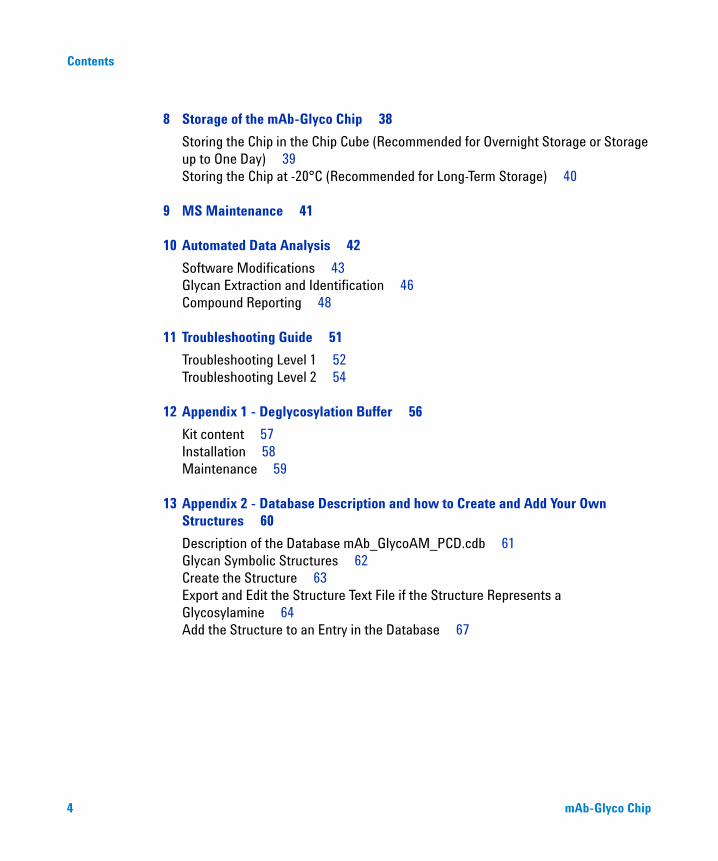
Agilent mAb-Glyco Chip · 2016-08-30 · mAb-Glyco Chip 3 Contents Contents 1 Agilent mAb-Glyco...
68
Agilent Technologies Agilent mAb-Glyco Chip User's Guide
Transcript of Agilent mAb-Glyco Chip · 2016-08-30 · mAb-Glyco Chip 3 Contents Contents 1 Agilent mAb-Glyco...

Agilent Technologies
Agilent mAb-Glyco Chip
User's Guide

Notices© Agilent Technologies, Inc. 2011
No part of this manual may be reproduced in any form or by any means (including elec-tronic storage and retrieval or translation into a foreign language) without prior agree-ment and written consent from Agilent Technologies, Inc. as governed by United States and international copyright laws.
Manual Part NumberG4240-90022
Edition08/2011
Printed in Germany
Agilent TechnologiesHewlett-Packard-Strasse 8 76337 Waldbronn
This product may be used as a com-ponent of an in vitro diagnostic sys-tem if the system is registered with the appropriate authorities and com-plies with the relevant regulations. Otherwise, it is intended only for gen-eral laboratory use.
Warranty
The material contained in this docu-ment is provided “as is,” and is sub-ject to being changed, without notice, in future editions. Further, to the max-imum extent permitted by applicable law, Agilent disclaims all warranties, either express or implied, with regard to this manual and any information contained herein, including but not limited to the implied warranties of merchantability and fitness for a par-ticular purpose. Agilent shall not be liable for errors or for incidental or consequential damages in connection with the furnishing, use, or perfor-mance of this document or of any information contained herein. Should Agilent and the user have a separate written agreement with warranty terms covering the material in this document that conflict with these terms, the warranty terms in the sep-arate agreement shall control.
Technology Licenses The hardware and/or software described in this document are furnished under a license and may be used or copied only in accor-dance with the terms of such license.
Restricted Rights LegendIf software is for use in the performance of a U.S. Government prime contract or subcon-tract, Software is delivered and licensed as “Commercial computer software” as defined in DFAR 252.227-7014 (June 1995), or as a “commercial item” as defined in FAR 2.101(a) or as “Restricted computer soft-ware” as defined in FAR 52.227-19 (June 1987) or any equivalent agency regulation or contract clause. Use, duplication or dis-closure of Software is subject to Agilent Technologies’ standard commercial license terms, and non-DOD Departments and Agencies of the U.S. Government will
receive no greater than Restricted Rights as defined in FAR 52.227-19(c)(1-2) (June 1987). U.S. Government users will receive no greater than Limited Rights as defined in FAR 52.227-14 (June 1987) or DFAR 252.227-7015 (b)(2) (November 1995), as applicable in any technical data.
Safety Notices
CAUTION
A CAUTION notice denotes a hazard. It calls attention to an operating procedure, practice, or the like that, if not correctly per-formed or adhered to, could result in damage to the product or loss of important data. Do not proceed beyond a CAUTION notice until the indicated condi-tions are fully understood and met.
WARNING
A WARNING notice denotes a hazard. It calls attention to an operating procedure, practice, or the like that, if not correctly performed or adhered to, could result in personal injury or death. Do not proceed beyond a WARNING notice until the indi-cated conditions are fully under-stood and met.
mAb-Glyco Chip

Contents
Contents
1 Agilent mAb-Glyco Chip 5
Intended Use 5Kit Contents 6
2 System Preparation 7
Hardware Modifications 7Software Modifications 10
3 Reagent Preparation and Storage 11
Deglycosylation Buffer (store at 4°C) 12System Conditioning Reagent (store at -20°C) 13Glycan Standards (store at -20°C) 13Antibody Sample (store at 4°C) 14
4 Mass Hunter Methods Shipped with mAb-Glyco Chip 15
Acquisition Methods 16Data Analysis Method 17
5 Glycan Nomenclature Used in the mAb-Glyco Chip Database 18
6 Conditioning of the HPLC-Chip/MS System 20
Preparation of the System Conditioning Reagent 21System Conditioning Procedure 21Checking the Conditioning of the HPLC System 22
7 Operating the mAb-Glyco Chip 23
Getting Started – Chromatographic Checkout 24Layout of the mAb-Glyco Chip 26Description of the mAb-Glyco Chip Workflow 27Functional Checkout – On-Chip Deglycosylation 33Before Injecting your Samples - Checklist 37
mAb-Glyco Chip 3
Contents
8 Storage of the mAb-Glyco Chip 38
Storing the Chip in the Chip Cube (Recommended for Overnight Storage or Storage up to One Day) 39Storing the Chip at -20°C (Recommended for Long-Term Storage) 40
9 MS Maintenance 41
10 Automated Data Analysis 42
Software Modifications 43Glycan Extraction and Identification 46Compound Reporting 48
11 Troubleshooting Guide 51
Troubleshooting Level 1 52Troubleshooting Level 2 54
12 Appendix 1 - Deglycosylation Buffer 56
Kit content 57Installation 58Maintenance 59
13 Appendix 2 - Database Description and how to Create and Add Your Own Structures 60
Description of the Database mAb_GlycoAM_PCD.cdb 61Glycan Symbolic Structures 62Create the Structure 63Export and Edit the Structure Text File if the Structure Represents a Glycosylamine 64Add the Structure to an Entry in the Database 67
4 mAb-Glyco Chip

mAb-Glyco Chip
Agilent mAb-Glyco Chip 1
Intended Use 5
Kit Contents 6
Intended Use
The Agilent mAb-Glyco Chip is designed for on-chip deglycosylation of monoclonal antibodies (mAbs) as well as subsequent on-chip enrichment, separation and MS based detection of cleaved N-glycans with an Agilent HPLC-Chip/MS system. Deglycosylation is based on an integrated immobilized PNGase F enzyme reactor column.
5Agilent Technologies

1 Agilent mAb-Glyco ChipKit Contents
Kit Contents
Kit Components
Reagent Kit(part of kit
components)
mAb-Glyco ChipEnablement Kit
Components (hasto be ordered
seperately)
p/n Description
mAb-Glyco Chip (not orderable)
G4240-64022 Reagent Kit
mAb-Glyco Chip Content Disk (not orderable)
G4240-90023 Quick Start Guide
G4290-90226 Data Sheet
p/n Description
G4240-64023 Deglycosylation Buffer (user must add 3 % ACN)
System Conditioning Reagent, lyophilized (not orderable)
Glycan Standards, lyophilized (not orderable)
Antibody Standard, ready to use (not orderable)
p/n Description
G4240-64025 mAb-Glyco Chip Enablement Kit
5043-0223 Safety Cap
5043-0272 PTFE Adapter
5062-2483 Solvent tubing, 3.1 mm OD, 5 m
5063-6598 Tefzel ferrules and SSL lock rings, 1/8 inch, 10/pck
5063-6599 PPS nuts, 1/8 inch, 10/pck
01018-60025 Solvent inlet filter, stainless steel
8710-1930 Plastic tubing cutter
5067-1582 Inline Micro Filter kit, 0.5 µm, PEEK
G4240-90022 mAb-Glyco Chip User’s Guide
6 mAb-Glyco Chip

mAb-Glyco Chip
System Preparation 2
Hardware Modifications 7
Software Modifications 10
Hardware Modifications
Implement the following hardware modifications for proper operation of the mAb-Glyco Chip and to assure maximum chip lifetime.
1 Chip Cube configuration – Capillary Connections
The mAb-Glyco Chip is designed such that for functional operation (deglycosylation and glycan separation) the Chip Cube has to be configured in backflush mode. If the Chip Cube is configured in forward flush mode, no cleaved glycans will be transferred onto the PGC enrichment column, and thus no sample will be detected. Refer to Table 1 on page 8 and Figure 1 on page 8 for the correct plumbing of the HPLC-Chip/MS system.
CAUTION Significant decrease in chip lifetime
Operating the chip without installed enablement kit can lead to significant decrease in chip lifetime.
➔ Install the mAb-Glyco Chip Enablement Kit prior to using the mAb-Glyco Chip.
7Agilent Technologies

2 System PreparationHardware Modifications
Figure 1 Solvent connection to the Chip Cube for operation of the mAb-Glyco Chip (backflush)
Table 1 Plumbing of the HPLC-Chip/MS system
Port Capillary Comment
1 n/a Not used
2 Orange capillary (Fused silica/PEEK capillary, 15 µm, 90 cm (p/n G4240-87300))
Nanoflow pump to Chip Cube
3 Blue capillary (Fused silica/PEEK capillary 75 µm, 100 cm (p/n G4240-87303))
(for calibrant delivery via optional syringe pump)
4 n/a Not used
5 Yellow capillary (Fused silica/PEEK capillary 25 µm, 105 cm (p/n G4240-87301))
Sampler to Chip Cube via Inline Micro Filter
6 Black capillary (Fused silica/PEEK capillary 100 µm, 100 cm (p/n G4240-87302))
Chip Cube loading path to waste
8 mAb-Glyco Chip

System Preparation 2Hardware Modifications
2 Injection loop
The 8 µL injection loop (Loop capillary (p/n G1375-87315)) has to be installed in the micro autosampler in order to guarantee proper operation of the mAb-Glyco Chip. Due to the use of a time-based sample loading procedure, an incorrect injection loop volume may lead to an undefined loading procedure and thus to the absence of sample or reduced sample signals.
3 Transfer capillary between micro wellplate sampler and Chip Cube
A 105 cm long, 25 µm ID PEEK coated fused silica capillary (Fused silica/PEEK capillary 25 µm, 105 cm (p/n G4240-87301)) has to be installed between the Autosampler and the Chip Cube. Due to the use of a time-based sample loading procedure, changes in the length and diameter of the transfer capillary leads to an undefined sample loading process and thus to the absence of sample or reduced sample signals.
4 The mAb-Glyco Chip Enablement Kit
Install the mAb-Glyco Chip Enablement Kit (p/n G4240-64025) before operating the mAb-Glyco Chip. Please refer to the Appendix 1 for a detailed installation guide of Safety Bottle Cap for the Deglycosylation Buffer bottle. Please refer to the Installation Guide (p/n G4240-90120) for a detailed description of the Inline Micro Filter Kit.
5 Deglycosylation Buffer on Capillary Pump channel A1
Prior to operating the mAb-Glyco Chip, the Deglycosylation Buffer, provided in the mAb-Glyco Chip Kit, has to be installed on channel A1 of the Capillary Pump. Install the adapter from the mAb-Glyco Chip Enablement Kit onto the bottle containing the Deglycosylation Buffer. Insert the solvent filter and tubing from Capillary Pump channel A1 directly into this bottle and attach the bottle cap. Make sure to properly purge the system including the autosampler and transfer capillary to the Chip Cube before operating the mAb-Glyco Chip. The use of the Calib Chip (II) (p/n G4240-61010) or MS Calibration and Diagnostic Chip (p/n G4240-61001) is recommended for that purpose. Exposure of the enzyme reactor to organic solvents or solvents with inappropriate pH can irreversibly decrease the enzyme activity.
mAb-Glyco Chip 9
2 System PreparationSoftware Modifications
Software Modifications
Before operating the mAb-Glyco Chip, perform the following software modifications:
1 Run the Chip.ini Updater program from the provided mAb-Glyco Chip Content Disk. If the chip.ini file is not updated the mAb-Glyco Chip is not recognized by the Chip Cube hardware and thus cannot be operated.
2 Install the Firmware Update software from the provided mAb-Glyco Content Disk.
3 Run the Firmware Update program in order to update the firmware of the Autosampler, the Capillary Pump, the Nanoflow Pump and the Chip Cube. Refer to the “Help File Documentation” of the program for details on the Firmware update procedure. If the Chip Cube firmware is not updated, the mAb-Glyco Chip is not recognized by the Chip Cube. Operation is possible, but wrong positions are used for the outer valve rotor. This will result in a blockage of the loading flow path for both outer valve positions. As the Carry-Over Reduction (COR) functionality (see Mass Hunter acquisition software help for details) irreversibly harms the chip, the new firmware automatically ignores COR if a mAb-Glyco Chip is loaded.
4 Copy all Acquisition Methods (SystemConditioning.m, GlycanStandard.m, Antibody_100µmSeatCapillary.m, Antibody_75µmSeatCapillary.m, Antibody_50µmSeatCapillary.m) from the provided mAb-Glyco Chip Content Disk into the Mass Hunter method directory \MassHunter\Methods. The Mass Hunter folder can typically be found on drive D:. A detailed description of the mAb-Glyco Chip methods can be found in chapter Mass Hunter methods shipped with mAb-Glyco Chip.
5 Different Acquisition Methods for the mAb-Glyco Chip require the setting of different injection flush volumes (IFV). See Application Note 5981-5222EN for a detailed description of the IFV functionality. Make sure to set the right IFV when changing the method. A detailed description of the mAb-Glyco Chip methods, including their associated IFV settings, can be found in chapter Mass Hunter methods shipped with mAb-Glyco Chip.
10 mAb-Glyco Chip

mAb-Glyco Chip
Reagent Preparation and Storage 3
Deglycosylation Buffer (store at 4°C) 12
System Conditioning Reagent (store at -20°C) 13
Glycan Standards (store at -20°C) 13
Antibody Sample (store at 4°C) 14
The mAb-Gylco Chip Reagent Pack is designed specifically for use with the mAb-Glyco Chip. This accompanying reagent pack includes ready-to-use solutions and standards required for chip operation, diagnostics as well as maintenance. Upon receipt, store components at the recommended temperatures shown below and on individual component labels.
WARNING Toxic, flammable and hazardous solvents, samples and reagents
The handling of solvents, samples and reagents can hold health and safety risks.
➔ When working with these substances observe appropriate safety procedures (for example by wearing goggles, safety gloves and protective clothing) as described in the material handling and safety data sheet supplied by the vendor, and follow good laboratory practice.
➔ The volume of substances should be reduced to the minimum required for the analysis.
➔ Do not operate the instrument in an explosive atmosphere.
NOTE Carefully read and understand the following preparation, handling, and storage information. Inappropriate handling can lead to loss in the analytical performance of the system and a significant decrease in the chip lifetime.
11Agilent Technologies
3 Reagent Preparation and StorageDeglycosylation Buffer (store at 4°C)
Deglycosylation Buffer (store at 4°C)
The Deglycosylation Buffer is provided as a sterile solution with 0.02 % sodium azide (NaN3) as a preservative. It has an appropriate pH to keep the on-chip PNGase F enzyme reactor fully active and to preserve its functionality. Do not purge the mAb-Glyco Chip enzyme reactor with solvents other than the Deglycosylation Buffer from the mAb-Glyco Chip Reagent Kit.
• Add 3 % (v/v) acetonitrile (ACN) before first use.
• Bring the Deglycosylation Buffer to room temperature before use.
• Do not mix aliquots of the Deglycosylation Buffer from different bottles in order to minimize the risk of contamination.
• Connect the sterile Deglycosylation Buffer bottle directly to channel A1 of the Capillary Pump with the adapter and the bottle head from the enablement kit. Do not refill Deglycosylation Buffer into other HPLC bottles.
• Carefully purge the Capillary Pump and the Autosampler flow path when changing the Deglycosylation Buffer and before operating the mAb-Glyco Chip. Make sure that the Autosampler is in Mainpass mode during the purge process.
CAUTION Clogging, pressure instabilities and decrease in chip lifetime
Using inappropriately stored or handled Deglycosylation Buffer leads to chip clogging, pressure instabilities, and significant decrease in chip lifetime.
➔ Store the Deglycosylation Buffer at 4 °C while not in use, exchange it on a regular basis.
NOTE Discard the Deglycosylation Buffer three months after addition of 3 % ACN.
12 mAb-Glyco Chip

Reagent Preparation and Storage 3System Conditioning Reagent (store at -20°C)
System Conditioning Reagent (store at -20°C)
Refer to “Conditioning of the HPLC-Chip/MS System” on page 20 for a detailed description of the preparation and storage of the System Conditioning Reagent as well as for the system conditioning procedure and the conditioning state check.
Glycan Standards (store at -20°C)
The Glycan Standards is a dried mixture of five N-glycans commonly found on IgG antibodies (see “Getting Started – Chromatographic Checkout” on page 24 for details). This standard is intended for use as a chromatographic standard, for diagnosis of chromatographic changes of the chip, for analytical method development, and for adjustment of glycan ionization efficiency fluctuations.
1 Dissolve the lyophilized Glycan Standards in 200 µL Deglycosylation Buffer (3 % ACN added) in order to obtain a 0.25 pmol/µL working solution.
2 Vortex well to mix and briefly centrifuge to pellet any residual droplets.
3 To avoid repeated freeze/thaw cycles, prepare 20 µL aliquots and store at -20 °C until use.
4 Prior to use, transfer an aliquot into an appropriate HPLC vial, preferably into a 2 mL screw cap vial (Screw cap vial, 2 mL (p/n 5182-0556)), using PP micro inserts (PP micro inserts (p/n 5182-0549)) which are recommended for handling small sample volumes.
NOTE Do not use the System Conditioning Reagent for longer than three months after reconstitution.
NOTE Discard the Glycan Standards three months after reconstitution.
mAb-Glyco Chip 13

3 Reagent Preparation and StorageAntibody Sample (store at 4°C)
Antibody Sample (store at 4°C)
The Antibody Standard is a well characterized monoclonal IgG antibody spiked with an internal reference N-glycan. This standard is included for testing the mAb-Glyco Chip on functionality, for diagnostics and troubleshooting. The internal reference glycan is 2000 0A 0G with a mass of
1317.4938 ([M+H]+).
• The Antibody Standard is ready-to-use.
• Prior to use, transfer an aliquot into an appropriate HPLC vial, preferably into a 2 mL screw cap vial (Screw cap vial, 2 mL (p/n 5182-0556)), using a PP micro insert (PP micro inserts (p/n 5182-0549)) recommended for handling small sample volumes.
14 mAb-Glyco Chip

mAb-Glyco Chip
Mass Hunter Methods Shipped with mAb-Glyco Chip 4
Acquisition Methods 16
Data Analysis Method 17
15Agilent Technologies

4 Mass Hunter Methods Shipped with mAb-Glyco ChipAcquisition Methods
Acquisition Methods
The mAb-Glyco Chip is provided with a set of Mass Hunter acquisition methods that serve as default methods for all possible system configurations.
SystemConditioning.m (set Injection Flush Volume to 1 µL)
This method is used for system conditioning prior to using the mAb-Glyco Chip. Use this method in combination with a Calib Chip (II) (p/n G4240-61010) or MS Calibration and Diagnostic Chip (p/n G4240-61001) only. See “System Conditioning Procedure” on page 21 for a detailed description of the system conditioning procedure.
GlycanStandard.m (set Injection Flush Volume to 5 µL)
This method is used when on-chip deglycosylation is not required (e.g. injection of the Glycan Standards for chromatographic checkout or checkout of the MS performance; see section “Getting Started – Chromatographic Checkout” on page 24 for details). It keeps the enzyme reactor in the Bypass mode during both, sample loading and analysis, which allows for employing the volume-based IFV functionality for sample loading.
CAUTION Methods failure
The wrong length or inner diameter of the transfer capillary as well as removing the Micro Inline Filter causes the mAb-Glyco Chip methods to fail, as changes in the loading path volume change the time required for sample injection.
➔ Make sure that an Inline Micro Filter (Inline Micro Filter kit, 0.5 µm, PEEK (p/n 5067-1582)) and a yellow transfer capillary (Fused silica/PEEK capillary 25 µm, 105 cm (p/n G4240-87301)) is installed between the micro autosampler and the Chip Cube, which is the HPLC-Chip/MS standard configuration.
NOTE Copy the methods into \MassHunter\Methods before operating the mAb-Glyco Chip.
16 mAb-Glyco Chip

Mass Hunter Methods Shipped with mAb-Glyco Chip 4Data Analysis Method
Antibody_100µmSeatCapillary.m / Antibody_75µmSeatCapillary.m / Antibody_50µmSeatCapillary.m (set Injection Flush Volume to 0 µL)
These methods are used when on-chip deglycosylation has to be performed (e.g. injection of the Antibody Standard for functional checkout of the mAb-Glyco Chip; see section “Functional Checkout – On-Chip Deglycosylation” on page 33 for details). As the sample loading procedure for the mAb-Glyco Chip is based on time rather than on volume, the acquisition method has to be adjusted to the volume between the injector and the mAb-Glyco Chip. Depending on the inner diameter of the installed needle seat capillary installed in the autosampler of the HPLC system, the appropriate method has to be selected (see section “Description of the mAb-Glyco Chip Workflow” on page 27 for a detailed description of analysis workflow).
Data Analysis Method
The mAb-Glyco Chip is provided with a Mass Hunter data analysis method that serves as a default method for glycan extraction and identification by the molecular feature extractor (MFE) and database search.
mAb_Glycan_DataAnalysis.m
The method has pre-set values for the Molecular Feature Extractor and for the Search Database tool. Furthermore, it already has the correct setup of the mAb_glycans_AM_PCD.cdb database and the reporting templates.
NOTE Copy the method into \MassHunter\Methods before analyzing mAb-Glyco Chip data.
mAb-Glyco Chip 17

mAb-Glyco Chip
Glycan Nomenclature Used in the mAb-Glyco Chip Database 5
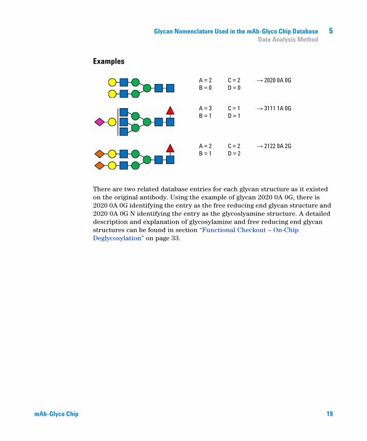
A database (mAb_glycans_AM_PCD.cdb) that contains all common glycan structures found on antibodies is provided with the mAb-Glyco Chip. The following four-number code nomenclature is used in the database:
Each glycan is characterized by four numbers ABCD, assuming a trimannosyl core (Figure 2 on page 18) is defined as a common core structure for all glycans.
• A … is the number of N-acetylglucosylamine (GlcNAc) residues outside the core
• B … is the presence (1) or absence (0) of core fucose
• C … is the number of galactose residues outside the core
• D … is the number of terminal sialic acid residues outside the core, whereas an attached A defines the sialic residue(s) as N-acetylneuraminic acid and a G as N-glycolylneuraminic acid
Figure 2 Schematic representation of the trimannosyl core
18 Agilent Technologies
Glycan Nomenclature Used in the mAb-Glyco Chip Database 5Data Analysis Method
Examples
There are two related database entries for each glycan structure as it existed on the original antibody. Using the example of glycan 2020 0A 0G, there is 2020 0A 0G identifying the entry as the free reducing end glycan structure and 2020 0A 0G N identifying the entry as the glycoslyamine structure. A detailed description and explanation of glycosylamine and free reducing end glycan structures can be found in section “Functional Checkout – On-Chip Deglycosylation” on page 33.
A = 2B = 0
C = 2D = 0
→ 2020 0A 0G
A = 3B = 1
C = 1D = 1
→ 3111 1A 0G
A = 2B = 1
C = 2D = 2
→ 2122 0A 2G
mAb-Glyco Chip 19
mAb-Glyco Chip
Conditioning of the HPLC-Chip/MS System 6
Preparation of the System Conditioning Reagent 21
System Conditioning Procedure 21
Checking the Conditioning of the HPLC System 22
Conditioning of the HPLC-Chip/MS system prior to using the mAb-Glyco Chip is required in order to minimize antibody adsorption effects to surfaces in the sample loading path of the autosampler and the HPLC-Chip Cube (injection loop, needle, needle seat assembly, autosampler valve, transfer capillary to Chip Cube). Unspecific antibody adsorption can lead to inconsistent results due to sample loss and significant carry-over effects.
20 Agilent Technologies

Conditioning of the HPLC-Chip/MS System 6Preparation of the System Conditioning Reagent
Preparation of the System Conditioning Reagent
1 Dissolve the lyophilized System Conditioning Reagent in 100 µL Deglycosylation Buffer (3 % ACN added).
2 Centrifuge the solution for 10 min at 13000 rpm to sediment any undissolved material.
3 Carefully take the supernatant, prepare 10 µL aliquots and store at -20 °C until use.
4 Thaw a 10 µL aliquot. Add 90 µL of Deglycosylation Buffer to obtain the ready-to-use System Conditioning Reagent solution.
5 Transfer the solution into an appropriate HPLC vial, preferably into a 2 mL screw cap vial (Screw cap vial, 2 mL (p/n 5182-0556)), using a PP micro insert (PP micro inserts (p/n 5182-0549)) recommended for handling small sample volumes.
System Conditioning Procedure
1 Load the Calib Chip (II) (p/n G4240-61010) or MS Calibration and Diagnostic Chip (p/n G4240-61001) and load the method SystemConditioning.m, provided with the mAb-Glyco Chip Kit.
2 Set the Injection Flush Volume to 1 µL.
3 Inject 8 µL of Conditioning Solution, repeat 4 times.
4 Inject 8 µL of Deglycosylation Buffer, repeat 2 times.
NOTE Discard the System Conditioning Reagent three months after reconstitution.
NOTE Store the System Conditioning solution in a cooled autosampler (around +5 °C) to minimize degradation.
NOTE The system conditioning procedure has to be performed with a MS Calibration and Diagnostic chip. Thus, no nanospray will be seen.
mAb-Glyco Chip 21

6 Conditioning of the HPLC-Chip/MS SystemChecking the Conditioning of the HPLC System
Checking the Conditioning of the HPLC System
The HPLC system can be checked for appropriate conditioning, using the mAb-Glyco Chip in combination with the Antibody Standard:
1 Load the mAb-Glyco Chip and load the appropriate method (see “Mass Hunter Methods Shipped with mAb-Glyco Chip” on page 15 for definition of all methods provided with the mAb-Glyco Chip). Example: Load method Antibody_75µmSeatCapillary.m in case your system is equipped with a blue 75 µm seat capillary.
2 Transfer the Antibody Standard into an appropriate HPLC vial, preferably into a 2 mL screw cap vial (Screw cap vial, 2 mL (p/n 5182-0556)), using a PP micro insert (PP micro inserts (p/n 5182-0549)) recommended for handling small sample volumes.
3 Set Injection Flush Volume to 0 µL.
4 Inject 2 µL of Antibody Standard.
5 Inject 2 µL of Deglycosylation Buffer as blank.
The system is properly conditioned if the carry-over is 5 % or less (carry-over is calculated by the ratio of the peak area of the most abundant glycan in the blank divided by the peak area of the glycan in the sample run prior to it, expressed as a percentage). In the case where carry-over is higher than 5 %, check the system for dead volumes or cracked capillaries in the sample loading path and repeat the system conditioning procedure.
A new conditioning cycle is required if the autosampler or any part in the sample flow path is changed.
CAUTION High sample carry-over
Due to unspecific antibody adsorption, an unconditioned HPLC-Chip/MS system might cause the mAb-Glyco Chip to perform inconsistently and might lead to high sample carry-over.
➔ Make sure, your system is conditioned properly.
22 mAb-Glyco Chip

mAb-Glyco Chip
Operating the mAb-Glyco Chip 7
Getting Started – Chromatographic Checkout 24
Layout of the mAb-Glyco Chip 26
Description of the mAb-Glyco Chip Workflow 27
Functional Checkout – On-Chip Deglycosylation 33
Before Injecting your Samples - Checklist 37
Apart from the Deglycosylation Buffer, mobile phases are not provided with the mAb-Glyco Chip Kit. Pump channels not listed in Table 2 on page 23 are not used.
Table 2 Required channels and mobile phases for operation of the mAb-Glyco Chip
Pump Channel Mobile Phase
Capillary Pump A1 Deglycosylation Buffer
Nanoflow Pump A1 H20 + 0.1 % formic acid
Nanoflow pump B1 ACN + 0.1 % formic acid
NOTE Channel B1 of the Capillary Pump is not needed when operating the mAb-Glyco Chip. To minimize the risk of accidentally exposing the enzyme reactor to organic solvents, it is strongly recommended to put the solvent line of channel B1 into the Deglycosylation Buffer bottle and thoroughly purge the channel.
23Agilent Technologies

7 Operating the mAb-Glyco ChipGetting Started – Chromatographic Checkout
Getting Started – Chromatographic Checkout
The Glycan Standards contain a mixture of five common IgG N-glycans. These glycans are mixed together in the approximate ratios indicated in Table 3 on page 24. This standard can be used for a chromatographic checkout of the porous graphitized carbon (PGC) columns or for method development.
1 Load the mAb-Glyco Chip and load the method GlycanStandard.m.
2 Set Injection Flush Volume to 5 µL.
3 Inject 4 µL of Glycan Standards.
Table 3 Components of the Glycan Standards, their theoretical m/z values for the [M+H]+ ions, and relative abundances in the mix.
Glycan Structure Glycan Denotation1
1 see chapter Glycan Nomenclature Used in the mAb-Glyco Chip Database for a description of the glycan nomenclature
[M+H]+ [m/z] Relative % in mix
2000 0A 0G 1317.4938 3
2100 0A 0G 1463.5517 60
2110 0A 0G 1625.6045 30
2120 0A 0G 1787.6574 5
Man5 1235.4407 2
NOTE Minor impurities may be present in the Glycan Standards in addition to the components listed in Table 3 on page 24. In case these impurities are glycans, they may be identified by database search.
24 mAb-Glyco Chip

Operating the mAb-Glyco Chip 7Getting Started – Chromatographic Checkout
Figure 3 on page 25 shows an overlay of Extracted Compound Chromatograms (ECCs) of all 5 glycans present in the Glycan Standards. Each glycan should result in a fully resolved pair of peaks which correspond to the two anomeric structures of free reducing end glycans. Due to the existence of two isomeric forms for the structure represented by glycan 2110 0A 0G (dependent on the position of the galactose residue), the anomers will separate into two double peaks when employing shallow gradients. The degree of separation of all four 2110 0A 0G glycan isomers can be used for method development.
Figure 3 Overlay of Extracted Compound Chromatograms of all 5 glycans obtained by a 4 µL injection of Glycan Standards on a 6520 Q-TOF, employing method GlycanStandard.m.
mAb-Glyco Chip 25

7 Operating the mAb-Glyco ChipLayout of the mAb-Glyco Chip
Layout of the mAb-Glyco Chip
The chip architecture of the mAb-Glyco Chip is illustrated in Figure 4 on page 26. The mAb-Glyco Chip consists of 3 columns: a 310 nL enzyme reactor (ER), packed with immobilized PNGase F beads, a 160 nL porous graphitized carbon enrichment column (PGC-EC) and a 43 mm long porous graphitized carbon separation column (PGC-SC).
Figure 4 Chip design of the mAb-Glyco Chip: enzyme reactor, enrichment, and separation column. The inner/outer rotor design allows for reactor isolation from the Capillary Pump flow path.
The mAb-Glyco Chip is designed as an inner/outer rotor device, which allows for switching the ER into or out of the Capillary Pump flow path. All possible chip valve position combinations are summarized in Table 4 on page 26.
Table 4 All possible rotor valve switching possibilities of the mAb-Glyco Chip
Inner Rotor (IR) Outer Rotor (OR) Column Nanoflow Pump Columns Capillary Pump
Enrichment Inline PGC-SC ER / PGC-EC
Enrichment Bypass PGC-SC PGC-EC
Analysis Inline PGC-EC / PGC-SC ER
Analysis Bypass PGC-EC / PGC-SC -
26 mAb-Glyco Chip

Operating the mAb-Glyco Chip 7Description of the mAb-Glyco Chip Workflow
Description of the mAb-Glyco Chip Workflow
The on-chip workflow of deglycosylation and subsequent glycan separation and detection comprises five fully automated steps:
• Sample injection
• Enzyme reactor fill
• Deglycosylation
• Glycan transfer
• Glycan separation/detection
Sample Injection (IR: Analysis / OR: Bypass)
The outer rotor is switched to bypass, the inner rotor to analysis. A volume of antibody (typically 2 µL), which is approximately 10 times higher than the volume of the packed ER is injected and loaded by the Capillary Pump onto the chip. Due to the fact that no column is in the Capillary Pump flow path, the sample plug is transported to the correct position without interacting with either the ER or the PGC-EC column packing material.
2, 5, 6 For details about the port numbers see “Hardware Modifications” on page 7.
mAb-Glyco Chip 27

7 Operating the mAb-Glyco ChipDescription of the mAb-Glyco Chip Workflow
Enzyme Reactor Fill (IR: Analysis / OR: Inline)
After the Capillary Pump transported the sample plug to the correct position, the ER is switched into the flow path for a defined amount of time, adapted to Capillary Pump flow rate and packed ER volume (typically 6 s at a Capillary Pump flow rate of 3 µL/min). This way, the ER is filled with sample. Sample is thus introduced to the on-chip workflow by a loop injection, whereas the ER cuts a piece of the sample from the heart of the injected plug by time based outer rotor valve switching.
2, 5, 6 For details about the port numbers see “Hardware Modifications” on page 7.
28 mAb-Glyco Chip

Operating the mAb-Glyco Chip 7Description of the mAb-Glyco Chip Workflow
Deglycosylation (IR: Analysis / OR: Bypass)
After the ER column is filled with sample, the outer rotor is turned back to bypass. The sample filled reactor is then allowed to react for a defined period of time (typically 4 min), whereas the Capillary Pump transports the fraction of the injected sample plug that is still in the system into waste and at the same moment flushes the system in order to minimize carryover.
2, 5, 6 For details about the port numbers see “Hardware Modifications” on page 7.
mAb-Glyco Chip 29

7 Operating the mAb-Glyco ChipDescription of the mAb-Glyco Chip Workflow
Glycan Transfer (IR: Enrichment / OR: Inline)
After the sample in the reactor is fully deglycosylated, the cleaved glycans are transferred from the ER to the PGC-EC by turning both rotors at the same time. This way, both columns, ER as well as PGC-EC, are switched into the Capillary Pump flow path. The glycans are flushed out of the reactor and trapped on the PGC-EC column. This step typically requires a volume of 3 µL at most.
2, 5, 6 For details about the port numbers see “Hardware Modifications” on page 7.
30 mAb-Glyco Chip

Operating the mAb-Glyco Chip 7Description of the mAb-Glyco Chip Workflow
Glycan Separation/Detection (IR Analysis / OR: Inline)
Finally, the enriched glycans are introduced to the Nanoflow Pump flow path by turning the inner rotor back to analysis, which allows for their separation and MS detection on the PGC-SC by initiating a regular reversed-phase gradient on the Nanoflow Pump. During analysis, the outer rotor keeps the inline position for cleaning and re-equilibration of the ER column with Deglycosylation Solvent delivered by the Capillary Pump.
Table 5 on page 32 summarizes all required workflow steps by illustrating the Chip Cube timetable and the Capillary as well as Nanoflow Pump timetable of a typical method, provided with the mAb-Glyco Chip Kit (see chapter “Mass Hunter Methods Shipped with mAb-Glyco Chip” on page 15 for detailed list and description of all provided methods).
2, 5, 6 For details about the port numbers see “Hardware Modifications” on page 7.
mAb-Glyco Chip 31

7 Operating the mAb-Glyco ChipDescription of the mAb-Glyco Chip Workflow
Table 5 Correlation between Chip Cube, Capillary and Nanoflow Pump time tables (method Antibody_75µmSeatCapillary.m as example)
Chip Cube Capillary Pump Nanoflow Pump
DescriptionTime [min]
IR ORFlow
[µL/min]solvent B
[%]Flow
[µL/min]solvent B
[%]
Sample Injection
0.00
Analysis
Bypass
3 0 0.5
2
Enzyme Reactor Fill
1.00 Inline
Deglycosylation
1.10 Bypass
Glycan Transfer
5.0 Enrichment
InlineGlycan Analysis
and Detection
6.0
Analysis
7.5 32
8.0 85
9.0 85
9.012
12.0
32 mAb-Glyco Chip

Operating the mAb-Glyco Chip 7Functional Checkout – On-Chip Deglycosylation
Functional Checkout – On-Chip Deglycosylation
The Antibody Standard provided in the mAb-Glyco Chip Kit is a well balanced mixture of a monoclonal IgG antibody and the 2000 0A 0G free reducing end
glycan with an [M+H]+ ion at 1317.4938 m/z (theoretical) as an internal reference. This standard is included for testing the mAb-Glyco Chip on functionality, for diagnostic purposes and troubleshooting.
1 Load the mAb-Glyco Chip and load the appropriate method (see chapter “Mass Hunter Methods Shipped with mAb-Glyco Chip” on page 15 for definition of all methods, provided with the mAb-Glyco Chip). Example: Load method Antibody_75µmSeatCapillary.m in case your system is equipped with a 75 µm seat capillary.
2 Transfer the Antibody Standard into an appropriate HPLC vial, preferably into 2 mL screw cap vials (Screw cap vial, 2 mL (p/n 5182-0556)), using PP micro inserts (PP micro inserts (p/n 5182-0549)) recommended for handling small sample volumes.
3 Set Injection Flush Volume to 0 µL.
4 Inject 2 µL of Antibody Standard.
A typical result of the Antibody Standard analyzed on the mAb-Glyco Chip is illustrated in Figure 5 on page 34. All glycans that are cleaved off from the antibody are colored red, whereas the internal standard (2000 0A 0G glycan) is colored black. On an intact mAb-Glyco Chip the most abundant antibody glycan should result in a similar peak height compared to that of the internal standard.
mAb-Glyco Chip 33

7 Operating the mAb-Glyco ChipFunctional Checkout – On-Chip Deglycosylation
Figure 5 Overlay of all glycan structures (ECCs) found in the Antibody Standard on a 6520 Q-TOF, employing method Antibody_75µmSeatCapillary.m.
Glycosylamine species are generated by enzymatic (PNGase F) cleavage of N-linked glycans that are bound to a polypeptide backbone by asparagine residues. These glycosylamine species however are reactive intermediates, which under neutral conditions are slowly hydrolyzed to free reducing end glycans. This conversion is catalyzed under acidic conditions. Due to an anomeric equilibrium, each glycosylamine results in two diastereomeric free glycan structures (see Figure 6 on page 35).
34 mAb-Glyco Chip

Operating the mAb-Glyco Chip 7Functional Checkout – On-Chip Deglycosylation
Figure 6 Mechanism of enzymatic (PNGase F) cleavage of N-linked glycans from a polypeptide backbone. Each linked glycan results in one glycosylamine intermediate, which slowly hydrolyzes into 2 anomeric free reducing end glycan structures.
Due to the fact that the mAb-Glyco Chip provides a fast approach for glycan cleavage and separation (deglycosylation and glycan separation within a couple of minutes), the predominately detected glycans are glycosylamines. Exposure of cleaved glycosylamines to acidic mobile phases (typically 0.1% FA as additive) on the Nanoflow Pump during the separation process, however, hydrolyzes some amount of the glycosylamine to free reducing end glycans (typically between 5-10%, depending on gradient time and steepness). These diastereomeric species can be resolved on the PGC separation column of the mAb-Glyco Chip. Theoretically, each cleaved N-glycan thus results in 3 peaks: One major glycosylamine and two small free reducing end glycan signals (if detectable).
mAb-Glyco Chip 35

7 Operating the mAb-Glyco ChipFunctional Checkout – On-Chip Deglycosylation
Figure 7 on page 36 illustrates a typical example of a monoclonal antibody, analyzed on the mAb-Glyco Chip. Four pairs of free reducing end glycans (two anomeric structures each) can be assigned to the four most abundant glycosylamine structures cleaved off the antibody (2100 0A 0G N, 2110 0A 0G N, 2120 0A 0G N and Man5 N). All other identified low abundant glycosylamine structures (marked orange) do not result in detectable free reducing end glycans.
Figure 7 Analysis of 75 ng antibody on the mAb-Glyco Chip. The 4 most abundant glycosylamine structures do result in detectable free reducing end glycans.
36 mAb-Glyco Chip
Operating the mAb-Glyco Chip 7Before Injecting your Samples - Checklist
Before Injecting your Samples - Checklist
• Do not use an injection volume smaller than 2 µL. The methods are optimized for an injection volume of 2 µL.
• An antibody concentration of 0.5 mg/mL should result in strong glycan signals. An injection concentration of 0.5 mg/mL results in 75 ng antibody on-column.
• It is strongly recommended to centrifuge the samples before injection.
• Do not inject more than 150 ng antibody on-column. Depending on the glycan pattern of the antibody, chromatographic overloading and mass overloading may occur.
• Make sure to set the correct Injection Flush Volume.
• Make sure that the correct method is loaded.
Higher antibody sample concentration results in higher cleaved glycan signals. Higher injection volume, however, will not lead to higher glycan signals, as the amount of sample that is introduced onto the mAb-Glyco Chip equals the volume of enzyme reactor (approx. 310 nL).
NOTE The first injection on a fresh mAb-Glyco Chip might not result in a consistent glycan pattern. However, subsequent injections should give reliable glycan cleavage, enrichment, and separation.
mAb-Glyco Chip 37
mAb-Glyco Chip
Storage of the mAb-Glyco Chip 8
Storing the Chip in the Chip Cube (Recommended for Overnight Storage or Storage up to One Day) 39
Storing the Chip at -20°C (Recommended for Long-Term Storage) 40
The enzyme reactor, packed with immobilized PNGase F (see Chapter “Layout of the mAb-Glyco Chip” on page 26 for a design description of the mAb-Glyco Chip) gradually loses its enzymatic activity when stored dry. In order to maintain the full efficiency of the mAb-Glyco Chip, it is thus required to protect the enzyme reactor from drying out.
CAUTION Decrease in enzyme activity
Storing the mAb-Glyco Chip at conditions other than described in this section may lead to rapid decrease in enzyme activity and to inconsistent results.
➔ Do strictly follow the recommended storage procedure.
38 Agilent Technologies

Storage of the mAb-Glyco Chip 8Storing the Chip in the Chip Cube (Recommended for Overnight Storage or Storage up to One Day)
Storing the Chip in the Chip Cube (Recommended for Overnight Storage or Storage up to One Day)
The mAb-Glyco Chip can be stored directly in the Chip Cube. This way of mAb-Glyco Chip handling is recommended for short-term storage up to one day. Storing the mAb-Glyco Chip in standby position of the Chip Cube is the preferred method for overnight storage, in case the chip is used the next day.
• In case the instrument is in operation, not in a sequence and no more analysis have to be performed, switch the instrument to STANDBY without ejecting the chip from the Chip Cube.
• In case the instrument is in operation, not in a sequence and it is intended to start another sequence, activate the script “SCP_InstrumentStandby” in the Post-Worklist command in the Worklist Run Parameters. This will automatically send the system to STANDBY after the sequence.
• In case the instrument is in operation and already in a sequence, add the script “SCP_InstrumentStandby” to your Worklist. This will automatically send the system to STANDBY after the sequence.
STANDBY keeps the chip tightly clamped between valve end plate and stator plate, and both rotors are switched to a “block” position, thus preventing the enzyme reactor from drying out. Long-term storage of the mAb-Glyco Chip in standby position of the Chip Cube is not recommended due to exposure of the enzyme reactor to the elevated temperature (~38 °C) inside the Chip Cube.
mAb-Glyco Chip 39

8 Storage of the mAb-Glyco ChipStoring the Chip at -20°C (Recommended for Long-Term Storage)
Storing the Chip at -20°C (Recommended for Long-Term Storage)
If the mAb-Glyco Chip will not be used one day or longer, the chip must be stored at -20 °C in order to avoid loss of enzymatic activity due to drying out of the enzyme reactor.
Follow this procedure for proper long-term storage of the mAb-Glyco Chip:
1 In case the chip has been stored in the Chip Cube, flush the enzyme reactor (inline position) with Deglycoslyation Buffer for a couple of minutes in order to assure that the enzyme reactor column is freshly wetted before freezing.
2 Eject the chip directly after operation.
3 Put the chip into its plastic storage box.
4 Immediately place the box with the mAb-Glyco Chip into a freezer at -20 °C.
NOTE Make sure that the enzyme reactor is wet before freezing the chip. If you are not sure whether the reactor is still wet, insert the chip into the Chip Cube and flush the enzyme reactor with Deglycosylation Buffer by turning the Capillary Pump on at 3 µL/min for 3 min.
40 mAb-Glyco Chip
mAb-Glyco Chip
MS Maintenance 9
The Deglycosylation Buffer contains 0.02 % NaN3 as preservative. Consequently, a sodium-containing plug of the size of the PGC enrichment column is injected into the ionization region with each injection being performed. Over time this may slowly result in a decrease in MS sensitivity.
In case a drop in MS sensitivity is noticed, it is recommended to eject the mAb-Glyco Chip, remove the Chip Cube interface from the MS and to perform a routine cleaning of the MS ion source region.
41Agilent Technologies

mAb-Glyco Chip
Automated Data Analysis 10
Software Modifications 43
Glycan Extraction and Identification 46
Compound Reporting 48
42 Agilent Technologies
Automated Data Analysis 10Software Modifications
Software Modifications
The mAb-Glyco Chip Content Disk contains all required tools to perform fully automated glycan extraction, identification, and reporting of antibody samples. In order to use this automated glycan data workflow, perform the following software modifications:
NOTE Mass Hunter Qualitative Analysis Software and the version of Personal Compound and Database Library Software that corresponds to the version of the Mass Hunter Qualitative Software has to be installed before performing the following modifications.
mAb-Glyco Chip 43
10 Automated Data AnalysisSoftware Modifications
For MassHunter Qualitative Analysis Software B.03.01
1 Copy the Data Analysis Method (mAb_Glycan_DataAnalysis.m) from the provided mAb-Glyco Chip Content Disk into the Mass Hunter method directory \MassHunter\methods. The MassHunter folder can typically be found on drive D:.
2 Copy the Reporting Templates “Glycan_Template_Letter.xltx” and “Glycan_Screening_Template_Letter.xltx” into \MassHunter\ReportTemplates\Qual\en-US\Letter and “Glycan_Template_A4.xltx” and “Glycan_Screening_Template_A4.xltx” into \MassHunter\ReportTemplates\Qual\en-US\A4.
3 If Mass Hunter Qualitative Software B.03.01 is installed, run the Qualitative Data Analysis B.03.01 SP 03 Installer. If SP 03 is not installed, the glycan structure viewer might not work properly.
4 Run the Database Installer. This installs the Glycan Database (mAb_Glyco_AM_PCD.cdb) onto the existing Mass Hunter Qualitative Software platform.
5 Start the Mass Hunter Qualitative Analysis software and load the method “mAb_Glycan_DataAnalysis.m”. In the Method Explorer, go to Find Compounds, Find by Molecular Feature and Mass Filter and define the file “mAb_Glyco_AM_PCD.cdb” as database. In the Method Explorer, go to Identify Compounds, Search Database and Database and define the file “mAb_Glyco_AM_PCD.cdb”.
6 In the Method Explorer, go to General, Common Reporting Options and Templates, choose \MassHunter\ReportTemplates\Qual\en-US\Letter or \MassHunter\ReportTemplates\Qual\en-US\A4 as the Report Template folder and define the compound report template.
44 mAb-Glyco Chip

Automated Data Analysis 10Software Modifications
For MassHunter Qualitative Analysis Software B.04.00
1 Copy the Data Analysis Method (mAb_Glycan_DataAnalysis.m) from the provided mAb-Glyco Chip Content Disk into the Mass Hunter method directory \MassHunter\methods. The MassHunter folder can typically be found on drive D:.
2 Copy the Reporting Templates “Glycan_Template_Letter.xltx” and “Glycan_Screening_Template_Letter.xltx” into \MassHunter\Report Templates\Qual\B.04.00\en- US\Letter and “Glycan_Template_A4.xltx” and “Glycan_Screening_Template_A4.xltx” into MassHunter\ReportTemplates\ Qual\B.04.00\en-US\A4.
3 Run the Database Installer. It can be found on the mAb-Glyco Content Disk under \PCDL\B.04.00. This installs the Glycan Database (mAb_Glyco_AM_PCD.cdb) onto the existing Mass Hunter Qualitative Software platform.
4 In the Method Explorer, go to Reports, Common Reporting Options, choose \MassHunter\Report Templates\Qual\B.04.00\en-US\Letter or \MassHunter\Report Templates\Qual\B.04.00\en-US\A4 as the Report Template folder and select Glycan Template or the Glycan Screening Template for compound report template.
mAb-Glyco Chip 45

10 Automated Data AnalysisGlycan Extraction and Identification
Glycan Extraction and Identification
Perform the following steps for automated glycan extraction and identification:
1 Open a sample file with Mass Hunter Qualitative Analysis and run the Molecular Feature Extractor (MFE) algorithm (Find Compounds/Find by Molecular Feature) on that data file.
2 Afterwards search all compounds, listed in the Data Navigator by database (Identify Compounds/Search Database). This step is necessary to attach glycan structure information to the identified hits and to visualize the structures.
Figure 8 on page 47illustrates the identification results of a typical antibody sample, which was analyzed on the mAb-Glyco Chip. All identified glycans are listed in the Data Navigator and are overlaid in the Chromatogram Results (Overlay of Extracted Compound Chromatograms (ECCs)). For a selected glycan structure (2100 0A 0G N in Figure 8 on page 47as example), the Structure Viewer shows the corresponding glycan structure. The detected m/z values, the assigned charge states and isotopes of the selected glycan hit are displayed in MS Spectrum Results and MS Spectrum Peak List.
As the glycan database contains an entry for the glycosylamine as well as the free reducing end glycan structure of each glycan (see section “Functional Checkout – On-Chip Deglycosylation” on page 33 for a detailed description of glycosylamines and free reducing end glycans), the Mass Hunter glycan analysis workflow finds pairs of free reducing end glycans (generated by hydrolysis) for the most abundant glycosylamines.
NOTE Load the method “mAb_Glycan_DataAnalysis.m” before analyzing data. This method has pre-set values for the Molecular Feature Extractor and the Search Database functionality and serves as a default method for the mAb-Glyco Chip (see section “Data Analysis Method” on page 17 for details).
46 mAb-Glyco Chip

Automated Data Analysis 10Glycan Extraction and Identification
Figure 8 Results of a MFE and Search Database glycan identification of a typical antibody sample, analyzed on the mAb-Glyco Chip.
mAb-Glyco Chip 47

10 Automated Data AnalysisCompound Reporting
Compound Reporting
For generating a report of the extracted and identified glycans, run the Compound Report on a processed data file. There are two reporting templates available for the mAb-Glyco Chip – the Glycan Template, the Glycan Screening Template.
Description of the Glycan Template
The Glycan Template reports the identified glycosylamines and free reducing end glycans without any processing or refinement. Reported values are Compound Label, Retention Time, Mass, Name, Formula, Target Mass, Mass Difference, Volume and Relative Ratio.
Description of the Glycan Screening Template
The Glycan Screening Template processes the identified glycosylamine and free reducing end glycan hits, whereas the template does not differentiate between glycan isomers. The processing scheme of the Glycan Screening Template is illustrated in Figure 9 on page 49. All glycosylamines with same mass are clustered and the volumes are merged. The same processing is done for all free reducing end glycan isomers, and the MFE volumes of the merged free reducing end glycans are multiplied by an ionization factor that compensates for the difference in the ionization efficiency between a glycosylamine and its corresponding free reducing end glycan. After assigning all identified free reducing end glycan masses to their glycoslyamine precursors, the processed volumes (merged glycosylamine and merged free reducing end glycan volume) are summed up and the total volume is reported. As the volumes of the free reducing end glycans have been added to the glycosylamines, all free reducing end glycan entries are deleted as redundant information. Finally, glycosylamine isomers are visualized by color coding.
48 mAb-Glyco Chip

Automated Data Analysis 10Compound Reporting
Figure 9 Processing logic of the Glycan Screening Template.
mAb-Glyco Chip 49

10 Automated Data AnalysisCompound Reporting
Figure 10 on page 50shows a typical report generated with the Glycan Screening Template. In the example, three of all glycosylamine hits have isomers (Man5 N, Man4 N and 1100 0A 0G N). In the case where there are isomers found and assigned by color code, the reported total volume and the reported total vol% for each of the entries has the same value (sum of merged glycosylamine and merged free reducing end glycans) giving no indication about the volume of an entry alone (one row). The values in the color labeled fields represent the expected mass (target mass) of the glycosylamine.
Figure 10 Result table of a typical antibody sample, generated by using the Glycan Screening Template.
NOTE Consider that for each group of color labeled isomer entries, the total volume and the total vol% represents the merged isomer volume and thus contributes only one time to the overall glycan volume of the antibody sample.
50 mAb-Glyco Chip

mAb-Glyco Chip
Troubleshooting Guide 11
Troubleshooting Level 1 52
Troubleshooting Level 2 54
51Agilent Technologies
11 Troubleshooting GuideTroubleshooting Level 1
Troubleshooting Level 1
Figure 11 Troubleshooting Level 1
52 mAb-Glyco Chip

Troubleshooting Guide 11Troubleshooting Level 1
See “Hardware Modifications” on page 7, Figure 1 on page 8 for details
See Agilent Application Note 5989-5222 EN for details
See Installation Guide (p/n G4240-90120) for details
See “Hardware Modifications” on page 7 for details
See “Mass Hunter Methods Shipped with mAb-Glyco Chip” on page 15 for details
See “Layout of the mAb-Glyco Chip” on page 26 and “Functional Checkout – On-Chip Deglycosylation” on page 33 for details
See “Getting Started – Chromatographic Checkout” on page 24 for details
See Figure 7 on page 36 for example of separation
mAb-Glyco Chip 53
11 Troubleshooting GuideTroubleshooting Level 2
Troubleshooting Level 2
1.1, 1.2 and 1.3 of Troubleshooting Level 1 has to be performed.
Figure 12 Troubleshooting Level 2
54 mAb-Glyco Chip

Troubleshooting Guide 11Troubleshooting Level 2
See “Hardware Modifications” on page 7 and “Deglycosylation Buffer (store at 4°C)” on page 12 for details
According to “Conditioning of the HPLC-Chip/MS System” on page 20
According to “Conditioning of the HPLC-Chip/MS System” on page 20
See “Description of the mAb-Glyco Chip Workflow” on page 27 for details
See “Functional Checkout – On-Chip Deglycosylation” on page 33 for details on the antiobody sample concentration typically used for the mAb-Glyco chip
See “Description of the mAb-Glyco Chip Workflow” on page 27 and Table 5 on page 32 for a detailed explanation of the on-chip deglycosylation time
mAb-Glyco Chip 55
mAb-Glyco Chip
Appendix 1 - Deglycosylation Buffer 12
Kit content 57
Installation 58
Maintenance 59
The Deglycosylation Buffer is a potential nutrient solution for algae, bacteria, and fungi. To prevent airborne particles from entering the bottle, a safety bottle cap with venting valve and built-in 1 µm PTFE filter must be fitted directly onto the buffer bottle with the provided thread adapter.
56 Agilent Technologies
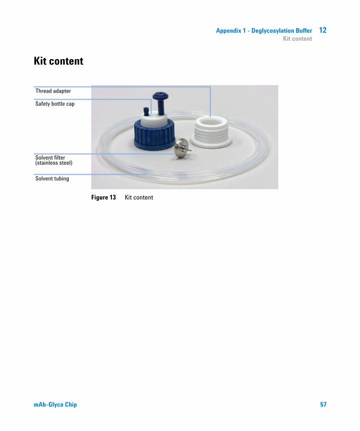
Appendix 1 - Deglycosylation Buffer 12Kit content
Kit content
Figure 13 Kit content
mAb-Glyco Chip 57

12 Appendix 1 - Deglycosylation BufferInstallation
Installation
1 Remove the cap of a new bottle of Deglycosylation Buffer and screw the thread adapter on.
2 Cut off an appropriate piece of solvent tubing and guide it through the fitting of the safety bottle cap.
3 Push the solvent inlet filter onto the end of the tubing.
4 Screw the safety bottle cap onto the thread adapter.
58 mAb-Glyco Chip

Appendix 1 - Deglycosylation Buffer 12Maintenance
5 Adjust the length of the solvent tubing such that the solvent filter just touches the bottom of the bottle and tighten the fitting finger-tight.
Maintenance
• Exchange the venting valve every six months.
• Replacement venting valves (p/n 5043-0232) can be ordered from Agilent (1 each).
mAb-Glyco Chip 59

mAb-Glyco Chip
Appendix 2 - Database Description and how to Create and Add Your Own Structures 13
Description of the Database mAb_GlycoAM_PCD.cdb 61
Glycan Symbolic Structures 62
Create the Structure 63
Export and Edit the Structure Text File if the Structure Represents a Glycosylamine 64
Add the Structure to an Entry in the Database 67
60 Agilent Technologies

Appendix 2 - Database Description and how to Create and Add Your Own Structures 13Description of the Database mAb_GlycoAM_PCD.cdb
Description of the Database mAb_GlycoAM_PCD.cdb
This database is a collection of accurate mass values for the most common N-linked glycans found on monoclonal antibodies. It contains a total of 144 structures of free glycans and their corresponding glycosylamine forms. The free glycan structures were verified to exist by reference to GlycoSuiteDB (revision 8, August 2005, now online at http://glycosuitedb.expasy.org/glycosuite/glycodb), and are produced in Homo sapiens (human), Mus musculus (house mouse), Cricetulus griseus (Chinese hamster), or combined expression systems from these species. Most likely, this database will be used in combination with the mAb-Glyco Chip for the identification and relative quantitation of N-linked glycans cleaved from monoclonal antibodies.
Of course, this collection represents only a fraction of the glycans that may be submitted for identification. Glycans are known for their myriad variations, extensions, isomeric forms, and anomeric forms which may be separated chromatographically depending on the conditions used. Also, glycans with different structures but having the identical molecular formula cannot be distinguished based on an accurate mass value alone. Lacking most of the standards to produce verifiable retention times, and lacking product ion spectra of the authentic compounds, these compounds having the same molecular formula are represented by a single entry in the database with a single composition and a generic structure.
In summary, it is likely you will want to add your own entries and associated structures to the database, and this document describes the process to do that.
mAb-Glyco Chip 61
13 Appendix 2 - Database Description and how to Create and Add Your Own StructuresGlycan Symbolic Structures
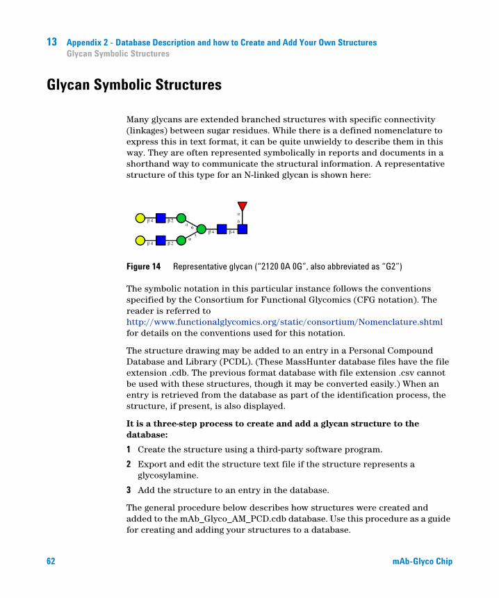
Glycan Symbolic Structures
Many glycans are extended branched structures with specific connectivity (linkages) between sugar residues. While there is a defined nomenclature to express this in text format, it can be quite unwieldy to describe them in this way. They are often represented symbolically in reports and documents in a shorthand way to communicate the structural information. A representative structure of this type for an N-linked glycan is shown here:
Figure 14 Representative glycan (“2120 0A 0G”, also abbreviated as “G2”)
The symbolic notation in this particular instance follows the conventions specified by the Consortium for Functional Glycomics (CFG notation). The reader is referred to http://www.functionalglycomics.org/static/consortium/Nomenclature.shtml for details on the conventions used for this notation.
The structure drawing may be added to an entry in a Personal Compound Database and Library (PCDL). (These MassHunter database files have the file extension .cdb. The previous format database with file extension .csv cannot be used with these structures, though it may be converted easily.) When an entry is retrieved from the database as part of the identification process, the structure, if present, is also displayed.
It is a three-step process to create and add a glycan structure to the database:
1 Create the structure using a third-party software program.
2 Export and edit the structure text file if the structure represents a glycosylamine.
3 Add the structure to an entry in the database.
The general procedure below describes how structures were created and added to the mAb_Glyco_AM_PCD.cdb database. Use this procedure as a guide for creating and adding your structures to a database.
62 mAb-Glyco Chip

Appendix 2 - Database Description and how to Create and Add Your Own Structures 13Create the Structure
Create the Structure
To create the structures in mAb_Glyco_AM_PCD.cdb, the program GlycoWorkbench 2.0 (alpha build 35 or 66) from the European Carbohydrates Database project was used. This program is freely available and may be downloaded from http://www.glycoworkbench.org/. The structures were created using the following format:
• CFG notation mode
• Extended notation style (so the linkage information may be displayed)
• No display of reducing end indicator
• No display of masses
These structures were exported (not saved) using the file format glycoct_condensed, which makes a readable record of the residues and linkages.
For detailed instructions on using the GlycoWorkbench program, refer to the user’s manual that comes with this program.
NOTE The structures were drawn using the CFG notation mode, not the UOXF (University of Oxford) notation mode. The UOXF notation mode is not supported by the structure drawing components in the MassHunter products.
mAb-Glyco Chip 63

13 Appendix 2 - Database Description and how to Create and Add Your Own StructuresExport and Edit the Structure Text File if the Structure Represents a Glycosylamine
Export and Edit the Structure Text File if the Structure Represents a Glycosylamine
As described in “Functional Checkout – On-Chip Deglycosylation” on page 33, glycans are cleaved from the antibody using an immobilized form of the enzyme PNGase F on the Chip. The first glycan product formed has a glycosylamine function at the reducing end, and this slowly hydrolyzes to the free glycan form in a pH and temperature-dependent process. The chromatographic analysis on the Chip is fast enough that most of the cleaved glycan products are detected as the glycosylamine form rather than as the free glycan. Therefore, both the glycosylamine form and the free glycan form of the same basic glycan molecule must be included in the database to identify all products produced during an analysis using the mAb-Glyco Chip.
To denote the glycosylamine form of a glycan, the convention chosen in the mAb_Glyco_AM_PCD.cdb database is to add the substituent “1N” to the reducing end.
Figure 15 Structures for the glycosylamine form “2120 0A 0G N” (left) and free glycan form “2120 0A 0G” (right). Note the “1N” substituent on the glycosylamine structure.
64 mAb-Glyco Chip

Appendix 2 - Database Description and how to Create and Add Your Own Structures 13Export and Edit the Structure Text File if the Structure Represents a Glycosylamine
The GlycoWorkbench 2.0 program has no means of denoting this glycosylamine functionality explicitly. However, it will add other substituents e.g., phosphate, in this position. To create the “1N” label for the glycosylamine structures in the database, do the following:
1 Using GlycoWorkbench, create the free glycan form of the structure and export it (remember, use the glycoct_condensed file format).
2 Add a phosphate substituent in the 1-position of the first GlcNAc residue.
3 Export the structure to a different file name.
4 Open the second .glycoct_condensed file with a text editor e.g., Wordpad.
5 Change the word “phosphate” to the word “amino”.
6 Save the file.
Shown here is the file 2120 0A 0G N.glycoct_condensed after editing. The line “2s:amino” was the edited line.
RES
1b:b-dglc-HEX-1:5
2s:amino
3s:n-acetyl
4b:b-dglc-HEX-1:5
5s:n-acetyl
6b:b-dman-HEX-1:5
7b:a-dman-HEX-1:5
8b:b-dglc-HEX-1:5
9s:n-acetyl
10b:b-dgal-HEX-1:5
11b:a-dman-HEX-1:5
12b:b-dglc-HEX-1:5
13s:n-acetyl
14b:b-dgal-HEX-1:5
15b:a-lgal-HEX-1:5|6:d
mAb-Glyco Chip 65

13 Appendix 2 - Database Description and how to Create and Add Your Own StructuresExport and Edit the Structure Text File if the Structure Represents a Glycosylamine
LIN
1:1o(1+1)2n
2:1d(2+1)3n
3:1o(4+1)4d
4:4d(2+1)5n
5:4o(4+1)6d
6:6o(3+1)7d
7:7o(2+1)8d
8:8d(2+1)9n
9:8o(4+1)10d
10:6o(6+1)11d
11:11o(2+1)12d
12:12d(2+1)13n
13:12o(4+1)14d
14:1o(6+1)15d
66 mAb-Glyco Chip
Appendix 2 - Database Description and how to Create and Add Your Own Structures 13Add the Structure to an Entry in the Database
Add the Structure to an Entry in the Database
Once the structure file is created, it is added to a database entry just like any other chemical structure:
1 Open the database of choice using the PCDL Manager.
2 Enable editing of the database.
3 Add a new compound.
4 Enter the new name, mass and formula. In general, database identifications with glycans will use the ion type “neutral” rather than “anion” or “cation”.
5 Click on the tool next to the structure window to add the drawing.
6 Select the file extension glycoct_condensed, then navigate to the appropriate directory and select the desired structure file.
7 A message will appear: “The structure’s formula () and thus mass () differs from that in the Formula field. Apply the structure formula?” Click No to retain the numerical value in the mass field.
8 Click on the update entry field to save the information to the database.
The changes do not need to be saved again when leaving the PCDL Manager.
NOTE If you click on another entry before updating the current one, you will lose the changes to the current entry.
mAb-Glyco Chip 67
www.agilent.com
In This Book
The manual describes the following:
• System Preparation
• Reagent Preparation and Storage
• Mass Hunter methods shipped with mAb-Glyco Chip
• Conditioning of the HPLC-Chip/MS system
• Operating the mAb-Glyco Chip
• Storage of the mAb-Glyco Chip
• MS Maintenance
• Automated Data Analysis
• Troubleshooting
© Agilent Technologies 2011
Printed in Germany 08/2011
*G4240-90022**G4240-90022*G4240-90022
Agilent Technologies