Agilent Intuvo 9000 Gas Chromatograph Agilent Intuvo 9000 Troubleshooting 5 Shutdown Symptoms Column...
132
Agilent Technologies Agilent Intuvo 9000 Gas Chromatograph Troubleshooting
Transcript of Agilent Intuvo 9000 Gas Chromatograph Agilent Intuvo 9000 Troubleshooting 5 Shutdown Symptoms Column...

Agilent Intuvo 9000 Gas Chromatograph
Troubleshooting
Agilent Technologies
Notices© Agilent Technologies, Inc. 2017
No part of this manual may be reproduced in any form or by any means (including electronic storage and retrieval or translation into a foreign language) without prior agreement and written consent from Agilent Technologies, Inc. as governed by United States and international copyright laws.
Manual Part NumberG9000-90005
EditionSecond edition, June 2017First edition, September 2016
Printed in USA
Agilent Technologies, Inc.2850 Centerville Road Wilmington, DE 19808-1610 USA
安捷伦科技(上海)有限公司 上海市浦东新区外高桥保税区 英伦路 412 号 联系电话:(800)820 3278
WarrantyThe material contained in this document is provided “as is,” and is subject to being changed, without notice, in future editions. Further, to the maximum extent permitted by applicable law, Agilent disclaims all warranties, either express or implied, with regard to this manual and any information contained herein, including but not limited to the implied warranties of merchantability and fitness for a particular purpose. Agilent shall not be liable for errors or for incidental or consequential damages in connection with the furnishing, use, or performance of this document or of any information contained herein. Should Agilent and the user have a separate written agreement with warranty terms covering the material in this document that conflict with these terms, the warranty terms in the separate agreement shall control.
Safety Notices
CAUTIONA CAUTION notice denotes a hazard. It calls attention to an operating procedure, practice, or the like that, if not correctly performed or adhered to, could result in damage to the product or loss of important data. Do not proceed beyond a CAUTION notice until the indicated conditions are fully understood and met.
WARNINGA WARNING notice denotes a hazard. It calls attention to an operating procedure, practice, or the like that, if not correctly performed or adhered to, could result in personal injury or death. Do not proceed beyond a WARNING notice until the indicated conditions are fully understood and met.

Contents1 Concepts and General Tasks
Agilent Intuvo 9000 Troubleshooting
Concepts 10How to troubleshoot using this manual 10Error conditions 11
Systems Configured for Enhanced Communications 12
Configurable Items to Always Keep Current 13Inlet and detector configuration 13Automatic Liquid Sampler configuration 14Gas configuration 14
To View the Run Log, Maintenance Log, and Event Log 15Run Log 15Maintenance Log 15Event Log 15
Information to Obtain Before Calling Agilent for Service 16
2 ALS and Detector Symptoms
Plunger Errors 18Procedure 18
Vial Mishandled by ALS (7693A) 19
Alignment Light on 7693A/7650A Injector Tower is On 21
Syringe Needle Bends During Injection into Inlet 22
FID Fails Leakage Current Test 23Possible causes 23Procedure 23
NPD Fails Leakage Current Test 24
FID Fails Baseline Test 25
FID Does Not Ignite 26
FID Ignitor Does Not Glow During Ignition Sequence 27
Corrosion in FID Collector and Ignitor Glow Plug 28
FPD+ Does Not Ignite 29
NPD Adjust Offset Process Fails 31
NPD Bead Will Not Ignite 32
3
4
FPD+ Temperature Will Not Become Ready 33
Blinking Not Ready Light: Detector Hardware Fault/TCD Filament Voltage 34
3 Chromatographic Symptoms
Retention Times Not Repeatable 36Peak Areas Not Repeatable 37
Contamination or Carryover 38Isolate the source 38Check possible causes—all inlet and detector combinations 38
Larger Peaks Than Expected 41
Peaks Not Displayed/No Peaks 42
Baseline Rise During Oven Temperature Program 44
Poor Peak Resolution 45
Peak Tailing 46NPD Peak Tailing 47
Peak Boiling Point or Molecular Weight Discrimination Poor 48For any inlet operating in split mode with any detector 48For any inlet operating in splitless mode with any detector 48
Sample Decomposition in Inlet/Missing Peaks 49
Peak Fronting 50
Noisy Detector, Including Wander, Drift, and Baseline Spikes 51Noisy baseline 51Baseline wander and drift 53Baseline spiking 54
Low Peak Area or Height (Low Sensitivity) 55To Resolve Low Sensitivity with an FID 56
FID Flame Goes Out During a Run and Attempts to Reignite 57
FID Baseline Output Above 20 pA 59
FID Baseline Output at Maximum (~8 Million) 60
FPD+ Flame Goes Out During a Run and Attempts to Reignite 61
FPD+ Quenching/Repeatability 62
FPD+ Output Too High or Too Low 63
FPD+ Low Peak Areas 64
Agilent Intuvo 9000 Troubleshooting

Agilent Intuvo 9000 Troubleshooting
FPD+ Large Peak Width at Half-Height 65
FPD+ Baseline Output High, > 20 pA 66
NPD Solvent Quenching 67
NPD Response Low 68
NPD Baseline Output > 8 million 70
NPD Adjust Offset Process Not Functioning Properly 71
NPD Low Selectivity 72
Negative Peaks Seen with TCD 73
TCD Baseline Has Dampened Sinusoidal Noise Trailing Peaks (Ringing Baseline) 74
TCD Peaks Have Negative Dip on Tail 75
4 GC Not Ready Symptoms
GC Never Becomes Ready 78Flow Never Becomes Ready 79
Cannot Set a Flow or Pressure 80
A Gas Does Not Reach Setpoint Pressure or Flow 81
A Gas Exceeds Pressure Setpoint or Flow 82
The Inlet Pressure or Flow Fluctuates 83
Cannot Maintain a Pressure as Low as the Setpoint on a Split Inlet 84
The Measured Column Flow Does Not Equal the Displayed Flow 85
FID Does Not Ignite 86
FID Ignitor Does Not Glow During Injection Sequence 87
FID or NPD Measured Hydrogen and Makeup Gas Flows Much Less Than Setpoint 89
NPD Adjust Offset Process Fails 90
FPD+ Does Not Ignite 91
Valve Not Ready 93Gas sampling valves 93
Blinking Not Ready Light: Detector Hardware Fault/TCD Filament Voltage 94
5

5 Shutdown Symptoms
6
Column Shutdowns 96
Hydrogen Shutdowns 97Hydrogen used in inlets and auxiliary gas streams 97
Detector Air Shutdowns 99
9000 MS Shutdown 100Clearing an MS Shutdown 101After resolving an MS Shutdown 101
Thermal Shutdowns 102
6 GC Power On and Communication Symptoms
GC Does Not Turn On 104PC Cannot Communicate with GC 105
GC Cannot Communicate with a Configured MS or HS 106
GC Does Not Recover After Firmware Update 107
GC Turns On, Then Stops During Startup (During Self-Test) 108
7 Troubleshooting Tasks
To Measure a Column Flow 110Measuring FID, TCD, and FPD+ column flow 110Measuring NPD column flow 112
To Measure a Split Vent or Septum Purge Flow 114
To Measure a Detector Flow 115Measuring FID, TCD, and FPD+ flows 115Measuring NPD flows 118
To Perform the GC Self-Test 120
To Adjust the FID Lit Offset 121
To Verify That the FID Flame Is Lit 122
To Verify FID Ignitor Function During Ignition Sequence 123
To Measure FID Leakage Current 124
To Measure FID Baseline Output 125
To Isolate the Cause of FID Noise 126
To Measure NPD Leakage Current 127
To Check for a Plugged FID Jet 128
Agilent Intuvo 9000 Troubleshooting

Agilent Intuvo 9000 Troubleshooting
To Check for a Plugged NPD Jet 129
To Verify That the NPD Bead Is Ignited 130
To Verify That the FPD+ Flame Is Lit 131
When to Change Gas Purifiers 132
7

8
Agilent Intuvo 9000 Troubleshooting
Agilent Intuvo 9000 Gas ChromatographTroubleshooting
1Concepts and General TasksConcepts 10Systems Configured for Enhanced Communications 12Configurable Items to Always Keep Current 13Information to Obtain Before Calling Agilent for Service 16
9Agilent Technologies
1 Concepts and General Tasks
Concepts
10
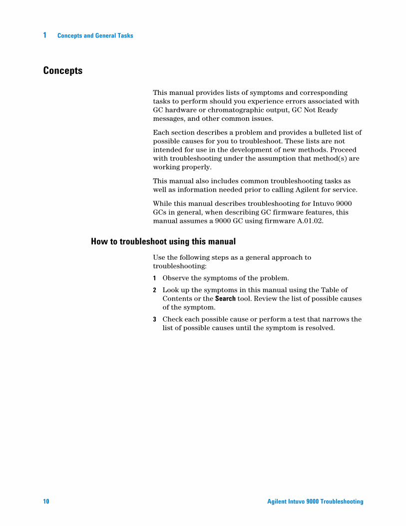
This manual provides lists of symptoms and corresponding tasks to perform should you experience errors associated with GC hardware or chromatographic output, GC Not Ready messages, and other common issues.
Each section describes a problem and provides a bulleted list of possible causes for you to troubleshoot. These lists are not intended for use in the development of new methods. Proceed with troubleshooting under the assumption that method(s) are working properly.
This manual also includes common troubleshooting tasks as well as information needed prior to calling Agilent for service.
While this manual describes troubleshooting for Intuvo 9000 GCs in general, when describing GC firmware features, this manual assumes a 9000 GC using firmware A.01.02.
How to troubleshoot using this manual
Use the following steps as a general approach to troubleshooting:1 Observe the symptoms of the problem.
2 Look up the symptoms in this manual using the Table of Contents or the Search tool. Review the list of possible causes of the symptom.
3 Check each possible cause or perform a test that narrows the list of possible causes until the symptom is resolved.
Agilent Intuvo 9000 Troubleshooting

Concepts and General Tasks 1
Error conditions
Agilent Intuvo 9000 Troubleshooting
If a problem occurs, a status message appears. If the message indicates broken hardware, more information may be available.
11
1 Concepts and General Tasks
Systems Configured for Enhanced Communications
12
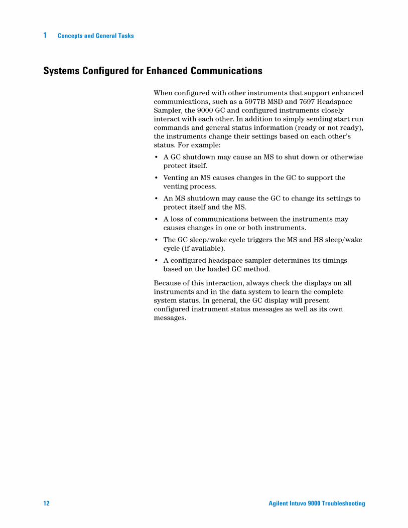
When configured with other instruments that support enhanced communications, such as a 5977B MSD and 7697 Headspace Sampler, the 9000 GC and configured instruments closely interact with each other. In addition to simply sending start run commands and general status information (ready or not ready), the instruments change their settings based on each other’s status. For example:
• A GC shutdown may cause an MS to shut down or otherwise protect itself.
• Venting an MS causes changes in the GC to support the venting process.
• An MS shutdown may cause the GC to change its settings to protect itself and the MS.
• A loss of communications between the instruments may causes changes in one or both instruments.
• The GC sleep/wake cycle triggers the MS and HS sleep/wake cycle (if available).
• A configured headspace sampler determines its timings based on the loaded GC method.
Because of this interaction, always check the displays on all instruments and in the data system to learn the complete system status. In general, the GC display will present configured instrument status messages as well as its own messages.
Agilent Intuvo 9000 Troubleshooting

Concepts and General Tasks 1
Configurable Items to Always Keep Current
Agilent Intuvo 9000 Troubleshooting
Certain configurable items in the GC must always be kept current. Failure to do so will lead to reduced sensitivity, chromatographic errors, and possible safety concerns.
Inlet and detector configuration
Be sure to configure the GC and all related components to reflect an inlet or detector change. Below are some examples of components to keep current after making changes to the inlet or detector:Liners: The appropriateness of liner type varies depending on the GC inlet mode, for example split mode versus splitless mode, and the analysis.
FPD+ filters: The FPD+ filters require different gas flows to function properly. Configure the flow according to the FPD+ filter installed (phosphorus versus sulfur).
NPD bead type: Always configure the NPD bead type. An incorrect type can lead to poor performance or premature bead failure.
13
1 Concepts and General Tasks
Automatic Liquid Sampler configuration
14
Keep the Automatic Liquid Sampler (ALS) configuration up-to-date to ensure proper operation. ALS items to keep current include installed syringe size and solvent and waste bottle usage.
Gas configuration
WARNING Always configure the GC appropriately when working with hydrogen. Hydrogen leaks quickly and poses a safety concern if too much of it is released into the air or into the GC oven.
Reconfigure the GC every time the gas type is changed. If the GC is configured to a gas other than what is actually being plumbed, incorrect flow rates will result.
Agilent Intuvo 9000 Troubleshooting
Concepts and General Tasks 1
To View the Run Log, Maintenance Log, and Event Log
Agilent Intuvo 9000 Troubleshooting
Use these logs to troubleshoot problems, especially when a message no longer appears on the display.
Run Log
For each run, the run log records deviations from the planned method. The run log information can be used for Good Laboratory Practice (GLP) standards and can be uploaded to an Agilent data system.Maintenance Log
The maintenance log contains an entry for each time an Early Maintenance Feedback limit is reached, reset, or changed. The log records details such as the counter item, the counter value, the new counter value, and whether or not the counter was reset (indicating a part replacement).Event Log
The event log records events such as shutdowns, warnings, faults, and GC state changes (start run, stop run, and so forth) that occur during GC operation.15
1 Concepts and General Tasks
Information to Obtain Before Calling Agilent for Service
16
Gather the following information before contacting Agilent for service:
• System health report (obtain using a web browser) contains this information. You can view the system help report from a web browser and print or save the report from the browser.
• Symptoms
• Problem description
• Hardware installed and parameters/configuration when the error occurred (sample, supply gas type, gas flow rates, detectors/inlets installed, and so forth)
• Any messages that appear on the GC display
• Results of any troubleshooting tests you have run
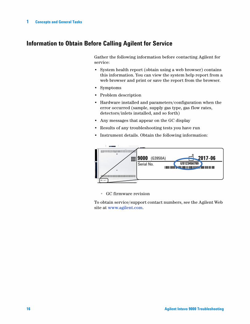
• Instrument details. Obtain the following information:
• GC firmware revision
To obtain service/support contact numbers, see the Agilent Web site at www.agilent.com.
9000 Serial No.
(G3950A) 2017-06US123456789
*US123456789*
Agilent Intuvo 9000 Troubleshooting

Agilent Intuvo 9000 Gas ChromatographTroubleshooting
2ALS and Detector SymptomsPlunger Errors 18Vial Mishandled by ALS (7693A) 19Alignment Light on 7693A/7650A Injector Tower is On 21Syringe Needle Bends During Injection into Inlet 22FID Fails Leakage Current Test 23NPD Fails Leakage Current Test 24FID Fails Baseline Test 25FID Does Not Ignite 26FID Ignitor Does Not Glow During Ignition Sequence 27Corrosion in FID Collector and Ignitor Glow Plug 28FPD+ Does Not Ignite 29NPD Adjust Offset Process Fails 31NPD Bead Will Not Ignite 32FPD+ Temperature Will Not Become Ready 33
17Agilent Technologies
2 ALS and Detector Symptoms
Plunger Errors
18
If the ALS reports a front or back plunger error, check the following possible causes:
• The syringe plunger is sticking or is not securely connected to the plunger carrier.
• The plunger solenoid is binding.
• The plunger carrier encoder is inoperable.
• The autoinjector plunger carrier mechanism will not move.
• The plunger does not move freely due to sample residue or wear. Install a new syringe, making sure to prime the syringe with solvent before installing.
Procedure
1 Remove the syringe and check it for plunger stickiness orbinding.
2 Replace the syringe if necessary. Refer to the documentation for the 7693A or 7650A, as applicable.
3 Check the viscosity of the sample against the viscosity parameter.
4 Reset the viscosity parameter if necessary.
5 Restart the sequence.
Agilent Intuvo 9000 Troubleshooting

ALS and Detector Symptoms 2
Vial Mishandled by ALS (7693A)
Agilent Intuvo 9000 Troubleshooting
Refer to your sampler operating documentation for additional information.
When you find a mishandled sample vial, do the following:
• Check for folds or wrinkles in the crimp cap, especially near the neck of the sample vial.
• Use Agilent-recommended sample vials.
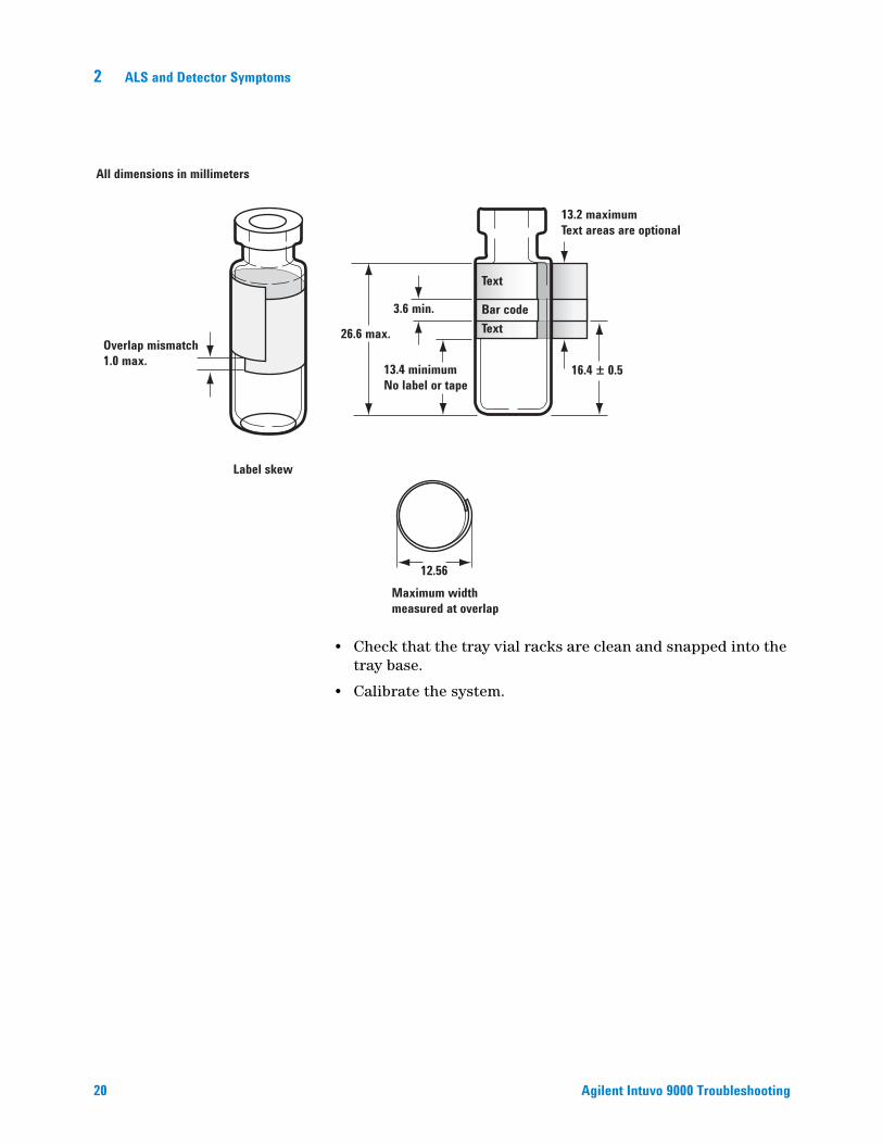
The figure below shows the critical dimensions for sample vials and microvial inserts to be used with the 7693A ALS system. These dimensions do not make up a complete set of specifications.
• Verify the transfer turret is installed if using a G4514A tray.
• Check sample labels (if applicable).
• Check that they are the correct size.
• Verify that the labels do not interfere with the gripper.
Vials are available with a write-on spot for easy marking. If you choose to make and apply your own labels, Agilent Technologies recommends the positioning and maximum label thickness shown in the figure below.
Body Diameter (BD) = 11.7 ± 0.2Cap Diameter (CD) = BD × 1.03 maximumAll dimensions in millimeters
CD
BD
33.5 ± 1.5Vial plus cap height
6.25 ± 0.25
3.7 min.
8.2 ± 0.2
32 ± 0.5
11.7 ± 0.2
25 minimum body height
Maximum height of a capped vial Crimp cap sample vial
19
20
2 ALS and Detector Symptoms
All dimensions in millimeters
Overlap mismatch1.0 max.
Label skew
26.6 max.
3.6 min.
13.4 minimumNo label or tape
16.4 ± 0.5
13.2 maximumText areas are optional
Text
Bar codeText
12.56Maximum width measured at overlap
• Check that the tray vial racks are clean and snapped into the tray base.
• Calibrate the system.
Agilent Intuvo 9000 Troubleshooting

ALS and Detector Symptoms 2
Alignment Light on 7693A/7650A Injector Tower is On
Agilent Intuvo 9000 Troubleshooting
If the Align Mode light is on, first verify that the turret is properly installed. Then, perform the alignment procedure as described in the 7693A Automatic Liquid Sampler Installation, Operation and Maintenance manual or the 7650A Automatic Liquid Sampler Installation, Operation and Maintenance manual.
21
2 ALS and Detector Symptoms
Syringe Needle Bends During Injection into Inlet
22
WARNING When troubleshooting the injector, keep your hands away from the syringe needle. The needle is sharp and may contain hazardous chemicals.
Refer to your ALS documentation for additional information:
• Check that the syringe is installed correctly into the syringe carriage.
• Check that the needle support and guide are clean. Remove any residue or septum deposits. Install a new needle support foot if necessary.
• Check that you are using the proper syringe. The combined length of the syringe barrel and needle should be approximately 126.5 mm.
• Check that the sample vial dimensions meet specification. See “Vial Mishandled by ALS (7693A)”.
• Check that the crimp cap is properly installed. Refer to your sampler documentation.
Agilent Intuvo 9000 Troubleshooting
ALS and Detector Symptoms 2
FID Fails Leakage Current Test
Possible causes
Agilent Intuvo 9000 Troubleshooting
A failed leakage current test usually indicates misassembly, contamination, or a damaged part.
Procedure
1 If you have just performed maintenance on the FID, firstverify that the detector was reassembled properly before troubleshooting detector problems.
2 Replace the PTFE (FID) for contamination.
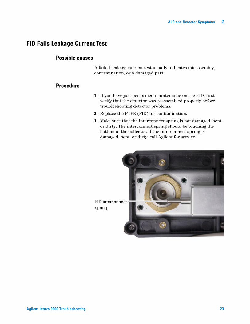
3 Make sure that the interconnect spring is not damaged, bent, or dirty. The interconnect spring should be touching the bottom of the collector. If the interconnect spring is damaged, bent, or dirty, call Agilent for service.
FID interconnect spring
23
2 ALS and Detector Symptoms
NPD Fails Leakage Current Test
24
A failed leakage current test usually indicates misassembly, contamination, or a damaged part.
If you have just performed maintenance on the NPD, first verify that the detector was reassembled properly before troubleshooting detector problems.
1 Replace the ceramic insulators. Restest.
2 Set the bead voltage to 0.0 V. Turn off the adjust offset. View the output (leakage current).
3 Remove the bead and store in a safe place.
4 Remove the three screws that secure the lid in place, then remove the lid.
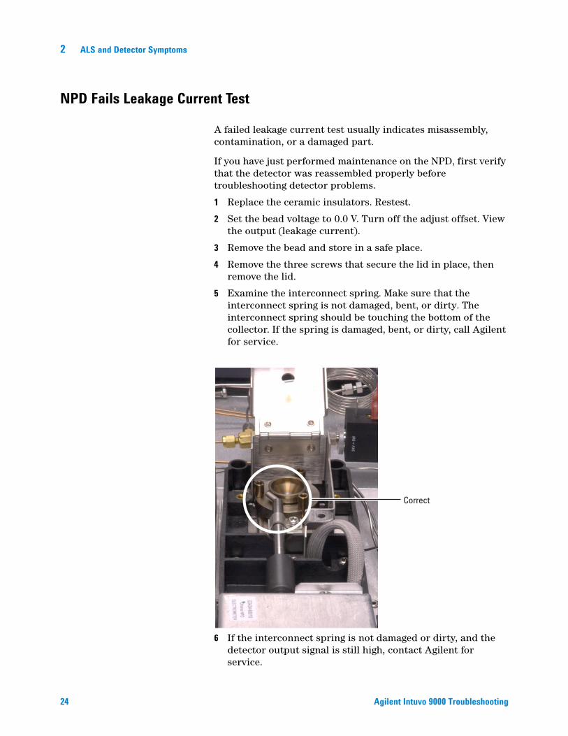
5 Examine the interconnect spring. Make sure that the interconnect spring is not damaged, bent, or dirty. The interconnect spring should be touching the bottom of the collector. If the spring is damaged, bent, or dirty, call Agilent for service.
6 If the interconnect spring is not damaged or dirty, and the detector output signal is still high, contact Agilent for service.
Correct
Agilent Intuvo 9000 Troubleshooting

ALS and Detector Symptoms 2
FID Fails Baseline Test
Agilent Intuvo 9000 Troubleshooting
If you have just performed maintenance on the FID, first verify that the detector was reassembled properly before troubleshooting detector problems.
If the FID fails the baseline test:
• Ensure the purity and quality of the gas.
• Replace dirty/expended chemical traps.
• Bakeout the detector.
25
2 ALS and Detector Symptoms
FID Does Not Ignite
26
• Verify that the Lit Offset is 2.0 pA.
• Ensure that the FID temperature is high enough for ignition (>150 °C). Agilent recommends >300 °C.
• Check that the FID ignitor glows during ignition sequence. (See To Verify FID Ignitor Function During Ignition Sequence.)
• Check that the air and hydrogen pressures meet Agilent’s recommendations (hydrogen > 35 psi [210 kPa] and air > 55 psi [380 kPa]). See the Agilent Intuvo 9000 GC, GC/MS, and ALS Site Preparation Guide.
• Try increasing the supply pressures to the FID flow module. This makes the flame easier to light without changing the setpoints.
• Increase hydrogen flow and decrease or turn off makeup gas flow until ignition occurs, then reduce them toward the method values. Experiment for the best values.
Increasing hydrogen flow and decreasing makeup flow will help the FID ignite more easily. If it will light under these modified conditions, the cause could be a partially clogged jet or a weak ignitor.
• Check for a plugged or partially plugged jet. (See To Check for a Plugged FID Jet.)
• Measure the FID flow rates. Actual flow rates should be within +/-10% of the setpoint. The hydrogen:air ratio greatly impacts ignition. Nonoptimal flow settings can prevent flame ignition. (See To Measure a Detector Flow.)
• Check the column flow rate. (See To Measure a Column Flow.) Hydrogen flow should be greater than the sum of the column flow and makeup flow.
• If the analysis permits, substitute nitrogen for helium as makeup.
Agilent Intuvo 9000 Troubleshooting

ALS and Detector Symptoms 2
FID Ignitor Does Not Glow During Ignition Sequence
Agilent Intuvo 9000 Troubleshooting
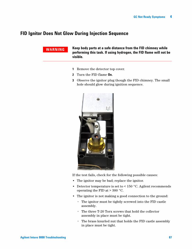
WARNING Keep body parts at a safe distance from the FID chimney while performing this task. If using hydrogen, the FID flame will not be visible.
1 Remove the detector top cover.
2 Turn the FID flame On.3 Observe the ignitor plug though the FID chimney. The small
hole should glow during ignition sequence.
If the test fails, check for the following possible causes:
• The ignitor may be bad; replace the ignitor.
• Detector temperature is set to < 150 °C. Agilent recommends operating the FID at > 300 °C.
• The ignitor is not making a good connection to the ground:
• The ignitor must be tightly screwed into the FID castle assembly.
• The three T-20 Torx screws that hold the collector assembly in place must be tight.
• The brass knurled nut that holds the FID castle assembly in place must be tight.
Perform FID maintenance if these parts are corroded or oxidized.
T-20 Torx screws (3)
Ignitor
Knurled nut
27
2 ALS and Detector Symptoms
Corrosion in FID Collector and Ignitor Glow Plug
28
Agilent recommends inspecting the collector and ignitor glow plug for corrosion while performing maintenance on the FID.
The FID combustion process results in condensation. This condensation, combined with chlorinated solvents or samples, causes corrosion and sensitivity loss.
To avoid corrosion, keep the detector temperature above 300 °C.
Agilent Intuvo 9000 Troubleshooting

ALS and Detector Symptoms 2
FPD+ Does Not Ignite
Agilent Intuvo 9000 Troubleshooting
• Check that the FPD+ temperature is high enough for ignition (> 150 °C).
• Check FPD+ flow rates and that they match the type of filter installed in the FPD+. The hydrogen:air ratio greatly impacts ignition. Nonoptimal flow settings can prevent flame ignition.
• Measure the actual detector flows. (See To Measure a Detector Flow.)
• Check that the FPD+ ignitor operates. (See To Verify That the FPD+ Flame Is Lit.)
• Check the column and makeup flow rates.
• Check the Lit offset value. The typical Lit offset value is 2.0. If it is zero, autoignition is turned off. If it is too large, the software will not recognize that the flame is lit and will shut the detector down.
• If the flame still will not light, there could be a large leak in the system. This results in measured flow rates being different from actual flow rates, causing non-ideal ignition conditions. Thoroughly leak check the whole system.
• Try increasing the supply pressures to the FPD+ flow module. This makes the flame easier to light without changing the setpoints.
• Under some operating conditions, the flame will light more easily with the vent tube removed. After lighting the flame, reinstall the vent tube.
Table 1 FPD+ recommended flows
Sulfur mode flows,mL/min
Phosphorus mode flows, mL/min
Carrier (hydrogen, helium,nitrogen, argon)
Capillary columns 1 to 5 1 to 5
Detector gases
Hydrogen 60 60
Air 60 60
Carrier + makeup 60 60
29

30
2 ALS and Detector Symptoms
• Try changing to the phosphorus mode flows, lighting the flame, and gradually alter the flows to the sulfur values.
• Check cable connections to coupling, coupling connection to glow plug, tight glow plug.
Agilent Intuvo 9000 Troubleshooting
ALS and Detector Symptoms 2
NPD Adjust Offset Process Fails
Agilent Intuvo 9000 Troubleshooting
• Inspect the jet to see if it is clogged. (See To Check for a Plugged NPD Jet.)
• Measure the actual detector flows. (See To Measure a Detector Flow.) If the hydrogen or makeup flows are zero or much lower than the displayed flow, suspect a plugged jet.
• Check the condition of the bead. Replace if necessary.
• Verify that the flow settings are correct.
• If the process still fails, there could be a large leak in the system. This causes measured flow rates to be different from actual flow rates. Thoroughly leak check the whole system.
• Set the equilibration time to 0.0.
31
2 ALS and Detector Symptoms
NPD Bead Will Not Ignite
32
• Set the equilibration time to 0.0.
• Verify that the flow settings are correct and appropriate.
• If the process still fails, there could be a large leak in the system. This causes measured flow rates to be different from actual flow rates. Thoroughly leak check the whole system, especially the detector column/adapter fitting.
• Check for fault messages. You can also read the bead voltage.
• Check the condition of the bead. Replace if necessary.
• Inspect the jet to see if it is clogged. (See To Check for a Plugged NPD Jet.)
• Measure the actual detector flows. (See To Measure a Detector Flow.) If the hydrogen or makeup flows are zero or much lower than the displayed flow, suspect a plugged jet.
Agilent Intuvo 9000 Troubleshooting
ALS and Detector Symptoms 2
FPD+ Temperature Will Not Become Ready
Agilent Intuvo 9000 Troubleshooting
If the FPD+ emission block temperature will not become ready:
• Check the oven temperature. If the oven temperature is high (over 325 °C) for a long time, set the emission block temperature to its highest value (165 °C).
• Check the transfer line temperature. If the transfer line is set to a very high temperature (near 400 °C), set the emission block temperature to at least 150 °C.
33
2 ALS and Detector Symptoms
Blinking Not Ready Light: Detector Hardware Fault/TCD Filament Voltage
34
If the TCD filament is open, the Not Ready LED blinks and the GC will not become Ready.
Agilent Intuvo 9000 Troubleshooting

Agilent Intuvo 9000 Gas ChromatographTroubleshooting
3Chromatographic SymptomsRetention Times Not Repeatable 36Peak Areas Not Repeatable 37Contamination or Carryover 38Larger Peaks Than Expected 41Peaks Not Displayed/No Peaks 42Baseline Rise During Oven Temperature Program 44Poor Peak Resolution 45Peak Tailing 46Peak Boiling Point or Molecular Weight Discrimination Poor 48Sample Decomposition in Inlet/Missing Peaks 49Peak Fronting 50Noisy Detector, Including Wander, Drift, and Baseline Spikes 51Low Peak Area or Height (Low Sensitivity) 55FID Flame Goes Out During a Run and Attempts to Reignite 57FID Baseline Output Above 20 pA 59FID Baseline Output at Maximum (~8 Million) 60FPD+ Flame Goes Out During a Run and Attempts to Reignite 61FPD+ Quenching/Repeatability 62FPD+ Output Too High or Too Low 63FPD+ Low Peak Areas 64FPD+ Large Peak Width at Half-Height 65FPD+ Baseline Output High, > 20 pA 66NPD Solvent Quenching 67NPD Response Low 68NPD Baseline Output > 8 million 70NPD Adjust Offset Process Not Functioning Properly 71NPD Low Selectivity 72Negative Peaks Seen with TCD 73TCD Baseline Has Dampened Sinusoidal Noise Trailing Peaks (Ringing Baseline) 74TCD Peaks Have Negative Dip on Tail 75
35Agilent Technologies
3 Chromatographic Symptoms
Retention Times Not Repeatable
36
• Replace the septum.
• Check for leaks in the inlet, liner (as applicable), and column connection.
• Check for sufficient carrier gas supply pressure. The pressure delivered to the GC must be at least 40 kPa (10 psi) greater than the maximum inlet pressure required at final oven temperature.
• Run replicates of known standards to verify the problem.
• Verify that you are using the correct liner type for the sample being injected.
• Consider if this is the first run. (Has the GC stabilized?)
• If using an FID or NPD and retention times increase (drift), check the jet for contamination or replace the jet.
• To Check for a Plugged FID Jet
• To Check for a Plugged NPD Jet
Agilent Intuvo 9000 Troubleshooting
Chromatographic Symptoms 3
Peak Areas Not Repeatable
Agilent Intuvo 9000 Troubleshooting
Check the ALS syringe operation.
• Replace the syringe.
• Check for leaks in the inlet, liner (as applicable), and column connection.
• Check sample level in vials.
• Run replicates of known standards to verify the problem.
• Consider if this is the first run. (Has the GC stabilized?)
For a multimode or split/splitless inlet in split mode, also check for:
• An abnormal split vent restriction.
37

3 Chromatographic Symptoms
Contamination or Carryover
38
If your output has contamination or unexpected peaks, do the following:
Isolate the source
1 Perform a solvent blank run using a new, pure source ofsolvent. If the contamination disappears, the problem may be either in the sample or solvent-related.
2 Perform a blank run (remove the syringe from the injector and start a run). If the contamination disappears, the problem is in the syringe.
3 Remove the column from the detector and cap the detector fitting. Perform another blank run. If the contamination disappears, the problem is in the inlet or column. If the contamination remains, the problem is in the detector.
Check possible causes—all inlet and detector combinations
Inlet, sampler, sample, gas supply• Check the septum type and installation. The vial septum may
be dissolving in the sample. Be sure the vial septum is resistant enough to the solvent you are using. Also ensure the vial septum is flat. If the vial septum is not flat, the needle tends to core the septum and drop pieces into the sample, causing contamination and ghost peaks.
• Perform complete inlet maintenance: Replace all consumable parts and bake out the inlet.
• Check for sample carryover from previous runs. Make several no-injection blank runs and see if the ghost peaks go away or get smaller.
• Check the septum purge flow. If it is too low, the septum may have collected contamination or condensate may be clogged in the purge line. For SS and MMI: Set the purge flow to at least 3 mL/min to keep the septum clean. See “To Measure a Column Flow”.
• Check all gas trap indicators and dates.
Agilent Intuvo 9000 Troubleshooting
Chromatographic Symptoms 3
Agilent Intuvo 9000 Troubleshooting
• Verify the gas purity. Perform replicate runs, several with a short interval between them, then several with a large interval. If the contamination peaks are larger for the runs made with the longer interval, suspect contaminated gas: the contamination has more time to deposit onto the column and liner.
• Check for supply tubing and fitting contamination.
• If you suspect that there is contamination in the inlet, perform the bakeout procedure.
• Verify the operation of the inlets. Clean the inlet and replace the contaminated inlet parts.
• Check the solvent level in the ALS wash bottles.
• Replace the ALS syringe if necessary.
• Check the sample injection volume. Verify that the ALS is injecting enough sample into the inlet. Use the Solvent Vapor Volume Calculator to determine how much of the sample should be injected.
• Ghost peaks are sometimes caused by contaminated sample vials. Try new or clean vials to see if ghost peaks disappear.
• Some samples change with heat or ultraviolet light. Check the sample stability.
Column, method• Perform column maintenance: Bake out contaminants, and
replace the guard chip. If using a jumper chip, consider installing a guard chip instead.
• If you suspect that there is contamination in the column, perform the bakeout procedure.
• Verify that the oven program temperature and time are sufficient for the samples being injected. Ghost peaks that are broader than adjacent sample peaks could be from a previous run.
• Inspect the column for contamination. High molecular weight samples that contain residues may cause the syringe, the inlet liner, or the first few inches of column to become contaminated.
• Install an Agilent column backflush system.
• Install a short column without a stationery phase, for example the OQ/PV column, 19019-60620E. Make a blank run. If the problem goes away, the column is the problem. perform column maintenance or replace the column. Alternately, use any known clean column.
39
40
3 Chromatographic Symptoms
Detector, detector gas supply• Check all gas trap indicators and dates.
• Verify the gas purity. Perform replicate runs, several with a short interval between them, then several with a large interval. If the contamination peaks are larger for the runs made with the longer interval, suspect contaminated gas: the contamination has more time to deposit onto the column and liner.
• Check for supply tubing and fitting contamination.
• If you suspect that there is contamination in the detector, perform the bakeout procedure.
• Verify the operation of the detectors. Replace the contaminated detector parts.
Agilent Intuvo 9000 Troubleshooting
Chromatographic Symptoms 3
Larger Peaks Than Expected
Agilent Intuvo 9000 Troubleshooting
• Check the autosampler injection volume. In the normal injection mode, the sampler uses fast injection to deliver a representative amount of the sample. Fast injection minimizes needle fractionation. Chromatograms from manual injection or slower auto injection devices show higher levels of low molecular weight materials versus higher molecular weight materials because the volatiles boil out of the needle faster than the higher weight materials.
• Check the vial caps. Loose vial caps can cause selective loss of lighter materials from a sample. The cap should not rotate easily if installed properly.
• Check configured syringe size. Some syringe sizes are specified at half-capacity. If the maximum syringe volume is marked at half-height on the barrel, not at the top of the barrel, enter twice the labeled volume when configuring the syringe size.
41
3 Chromatographic Symptoms
Peaks Not Displayed/No Peaks
42
• If using an autosampler:
• Ensure that there is sample in the vial.
• Verify that the ALS plunger carriage is secured to the syringe plunger.
• Check that the syringe is installed correctly and draws sample.
• Verify that the turret/tray is loaded correctly and injections are not from out-of-sequence vials.
• Watch to see that the sample is pulled into the syringe.
• Verify the detector in use is assigned to a signal.
• Check the column for proper installation.
• Ensure that the column is not plugged. (See “To Measure a Column Flow”.)
• Check for leaks.
• Check the flow settings, then measure the actual detector flows. (See “To Measure a Detector Flow”.)
• Some samples change with heat or ultraviolet light. Check sample stability.
• Check the sample level in the vial.
• If the sample is viscous, try the following:
• Increase the viscosity delay time.
• Dilute the sample in an appropriate low-viscosity solvent.
• Turn the tower fan off.
• For 7693A ALS, use the vial heater (accessory G4514A Bar Code Reader/Mixer/Heater) to warm the sample vial.
If the problem is with the detector, see Table 2.
Agilent Intuvo 9000 Troubleshooting

Chromatographic Symptoms 3
Agilent Intuvo 9000 Troubleshooting
Table 2 Detector troubleshooting
Detector Solution
FID, FPD+ • Verify that the electrometer is turned on.• Verify that the flame is still lit.
TCD • Verify that the filament is turned on.• Ensure that the reference gas is not set to zero. (The
filament will not turn on with zero reference gas flow.)
43
3 Chromatographic Symptoms
Baseline Rise During Oven Temperature Program
44
• Inspect the column for bleed.
• Check for leaks/oxygen in carrier gas supply. Oxygen can damage bonded phase capillary columns.
• Check gas supply oxygen trap indicator or date.
• Make solvent blank runs to evaluate baseline without sample.
• Make “no injection” blank runs (remove the syringe from the injector and start a run) to evaluate baseline without solvent.
• Check for contamination. (See Contamination or Carryover.)
• Consider the effect of column film thickness on bleed. Try using a column with a thinner film.
• Check for leaks at the column fittings.
• Prepare and use a column compensation profile.
Agilent Intuvo 9000 Troubleshooting
Chromatographic Symptoms 3
Poor Peak Resolution
Agilent Intuvo 9000 Troubleshooting
• Set column flow to optimum linear velocity.
• Install and use deactivated consumable parts in the inlet (for example, a liner).
• Perform column maintenance: Bake out contaminants, and replace the guard chip. If using a jumper chip, consider installing a guard chip instead.
• Select a higher resolution column.
45

3 Chromatographic Symptoms
Peak Tailing
46
The figure below shows an example of tailing peaks. When troubleshooting tailing peaks, consider:
• Which peaks are tailing?
• Are the tailing peaks active compounds, all compounds, or are there trends (such as early eluters or late eluters)?
• Check the column for severe contamination.
• For bonded and cross-linked phases, solvent rinse the column.
• Check for inlet contamination. Tailing will sometimes increase with compound retention. Clean the inlet and replace contaminated inlet parts. (See the Intuvo 9000 Maintenance manual.)
• Consider the column stationary phase (active column). This only affects active compounds. An active column usually produces tailing that increases with retention time.
• Replace the column.
• Verify that the column was installed properly.
• Confirm the installation is leak free.
• Check adapters (if installed) and liner for solid particles. If solid particles are visible, clean or replace.
• For capillary splitless injection, consider compatibility between the solvent and column.
• Use a different solvent. This will help in instances where there is more tailing for the early eluting peaks or those closest to the solvent front.
• If using a jumper chip, consider installing a guard chip instead.
Agilent Intuvo 9000 Troubleshooting
Chromatographic Symptoms 3
Agilent Intuvo 9000 Troubleshooting
• Verify that the injection technique is adequate. This is usually related to erratic plunger depression or having sample in the syringe needle.
• Verify the inlet temperature.
• If the temperature is too high, tailing is generally worse for early eluters. Decrease inlet temperature by 50 °C.
• If the temperature is too low, tailing usually increases with retention. Increase inlet temperature by 50 °C.
• Inspect any transfer lines for cold spots. Cold spots cause tailing that usually increases with retention time.
NPD Peak Tailing
For NPD, do the following:• Verify that you are using the correct bead for the sample being run. If you are analyzing phosphorus, install a black bead. White beads can cause peak tailing when phosphorus is being analyzed.
• Replace the ceramic insulators.
47

3 Chromatographic Symptoms
Peak Boiling Point or Molecular Weight Discrimination Poor
48
If you have trouble with peak boiling point or molecular weight discrimination (inlet discrimination), do the following:
• Check the inlet for contamination. Clean and change the liner if necessary. Replace all inlet consumable parts. See the Maintenance manual.
• Adjust the inlet temperature.
• Run standards against a known method to determine expected performance.
For any inlet operating in split mode with any detector
• Check liner type. Use a liner optimized for split analysis—onethat contains glass wool or other surface area packing to allow complete sample vaporization.
• Increase the inlet temperature and verify that the insulation cup is installed and contains insulation.
For any inlet operating in splitless mode with any detector
• Check the inlet for leaks.• Check liner type. Use a liner optimized for splitless analysis (deactivated, large volume).
• Verify that the oven starting temperature is less than the solvent boiling point.
• Check that the solvent vapor volume does not exceed the liner capacity.
• Check for appropriate purge delay time. (Liner volume/column flow)
Agilent Intuvo 9000 Troubleshooting

Chromatographic Symptoms 3
Sample Decomposition in Inlet/Missing Peaks
Agilent Intuvo 9000 Troubleshooting
• Lower the inlet temperature.
• Check for air or water in the carrier gas; verify gas purity and functionality of traps.
• Verify that the liner is appropriate for the sample being run.
• Perform complete inlet maintenance: Replace all consumable parts and bake out the inlet.
• Install a deactivated liner (if liner is used).
• Check for leaks at the septum and liner.
• Install an Agilent Direct Connect liner.
• Use a pulsed pressure method for quicker sample transfer to column.
• Bake out the inlet.
• Clean the inlet.
49
3 Chromatographic Symptoms
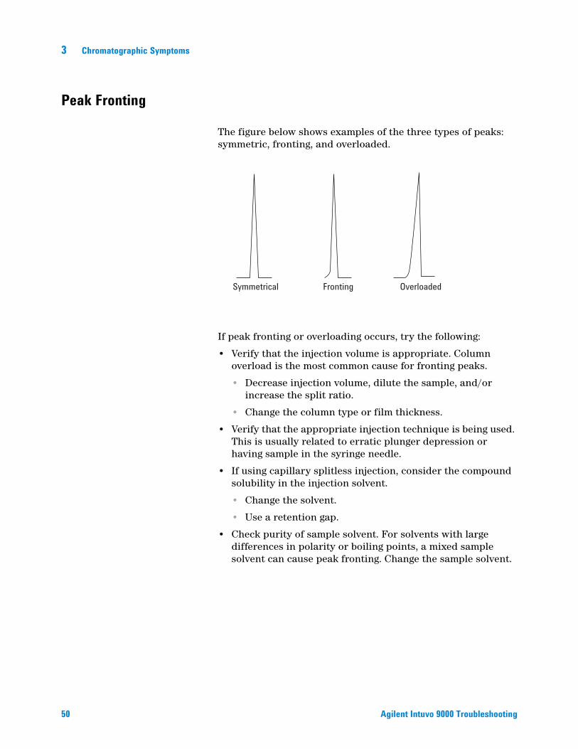
Peak Fronting
50
The figure below shows examples of the three types of peaks: symmetric, fronting, and overloaded.
If peak fronting or overloading occurs, try the following:
• Verify that the injection volume is appropriate. Column overload is the most common cause for fronting peaks.
• Decrease injection volume, dilute the sample, and/or increase the split ratio.
• Change the column type or film thickness.
• Verify that the appropriate injection technique is being used. This is usually related to erratic plunger depression or having sample in the syringe needle.
• If using capillary splitless injection, consider the compound solubility in the injection solvent.
• Change the solvent.
• Use a retention gap.
• Check purity of sample solvent. For solvents with large differences in polarity or boiling points, a mixed sample solvent can cause peak fronting. Change the sample solvent.
Symmetrical Fronting Overloaded
Agilent Intuvo 9000 Troubleshooting
Chromatographic Symptoms 3
Noisy Detector, Including Wander, Drift, and Baseline Spikes
Agilent Intuvo 9000 Troubleshooting
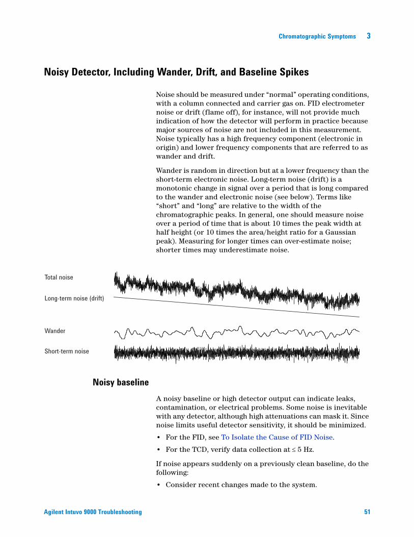
Noise should be measured under “normal” operating conditions, with a column connected and carrier gas on. FID electrometer noise or drift (flame off), for instance, will not provide much indication of how the detector will perform in practice because major sources of noise are not included in this measurement. Noise typically has a high frequency component (electronic in origin) and lower frequency components that are referred to as wander and drift.
Wander is random in direction but at a lower frequency than the short-term electronic noise. Long-term noise (drift) is a monotonic change in signal over a period that is long compared to the wander and electronic noise (see below). Terms like “short” and “long” are relative to the width of the chromatographic peaks. In general, one should measure noise over a period of time that is about 10 times the peak width at half height (or 10 times the area/height ratio for a Gaussian peak). Measuring for longer times can over-estimate noise; shorter times may underestimate noise.
Noisy baseline
Total noise
Long-term noise (drift)
Wander
Short-term noise
A noisy baseline or high detector output can indicate leaks, contamination, or electrical problems. Some noise is inevitable with any detector, although high attenuations can mask it. Since noise limits useful detector sensitivity, it should be minimized.
• For the FID, see To Isolate the Cause of FID Noise.
• For the TCD, verify data collection at 5 Hz.
If noise appears suddenly on a previously clean baseline, do the following:
• Consider recent changes made to the system.
51
52
3 Chromatographic Symptoms
• Bakeout the inlet.
Bakeout can reduce septum bleed and other contaminants. New septa may contribute noise from bleed of low molecular weight material. If noise decreases when inlet temperature is lowered, this is a likely cause. Use only high quality septa and store them where they cannot become contaminated.
• Verify the purity of carrier and detector gases. If a tank was replaced recently and the old one is still available and still has some gas in it, try the older tank to see if noise decreases.
If the new gas is so badly contaminated that it saturates traps, changing to the old one may show little improvement until the traps are replaced or regenerated. This problem is most common with nitrogen carrier gas. Deal with a reliable gas supplier.
• For the TCD, check for ambient air pressure fluctuations at the GC. Air currents from a fan or air conditioner blowing across the GC may interfere with gas exiting the detector. This is a possible, though not very likely cause of noise since detectors are well protected. Switching off the air current source or shielding the detector exit identifies this problem. Install the TCD outlet restrictor (G1532-60070).
• Loose connections in the detector or its signal path generate noise.
• Verify proper reassembly after recent maintenance.
• Inspect the detector for contamination.
If noise increases gradually to an unacceptable level, check the following possible causes:
• Bakeout the detector.
• Inspect the detector for contamination. Replace parts as needed. (See the 9000 Series Maintenance manual.)
• Inspect the column and inlet for contamination.
• Inspect the FID or NPD jet for contamination.
• To Check for a Plugged FID Jet
• To Check for a Plugged NPD Jet
• Verify that the FPD+ photomultiplier tube (PMT) is properly installed. If it is not, light leaks and ultimately noise will result.
FIDs are susceptible to gradual buildup of deposits in the detector. In extreme cases, spiking occurs along with increased noise level.
Agilent Intuvo 9000 Troubleshooting

Chromatographic Symptoms 3
Agilent Intuvo 9000 Troubleshooting
Carbon (black) deposits may form from solvents that burn poorly (primarily chlorinated materials and aromatics). Avoid such solvents if possible. If you must use them, be prepared to clean the detector regularly.
Silicon dioxide (white) is formed when bleed from a silicone column is burned in the flame. To minimize this, use low column loadings, select phases with high temperature limits, condition columns thoroughly before use, and use the lowest possible oven temperature for the analysis.
To remove either type of deposit, disassemble the detector and scrub with a small brush. A solvent (almost anything will do) helps flush away the particles. Agilent recommends replacing dirty collector and insulator parts.
Other factors that can contribute to noise:
• Oven temperature exceeds column maximum recommended temperatures.
Baseline wander and drift
Baseline wander or drift can occur when a flow or temperature setting is changed. If the system has not stabilized at the new conditions before it starts a run, some baseline changes are to be expected. The following cases assume that sufficient stabilization time has elapsed since the last change in operating conditions.Also consider whether the oven temperature program is sufficient.
Baseline drift is most often seen during temperature programming. To correct baseline drift, do the following:
• Verify that column compensation is used and the profile is current. (To compensate for bleed.)
• Verify that the column is conditioned.
• Check column bleed while at operating temperature.
• Check the signal mode assigned to the column in the data system.
• Check the column compensation profile. It may be too little (upscale drift) or too much (downscale drift).
This cause of drift is minimized by thorough column conditioning. Operating at a lower temperature reduces the drift but prolongs the analysis. Use of a chromatographically equivalent column with a higher temperature limit is also possible.
53
3 Chromatographic Symptoms
Baseline spiking
54
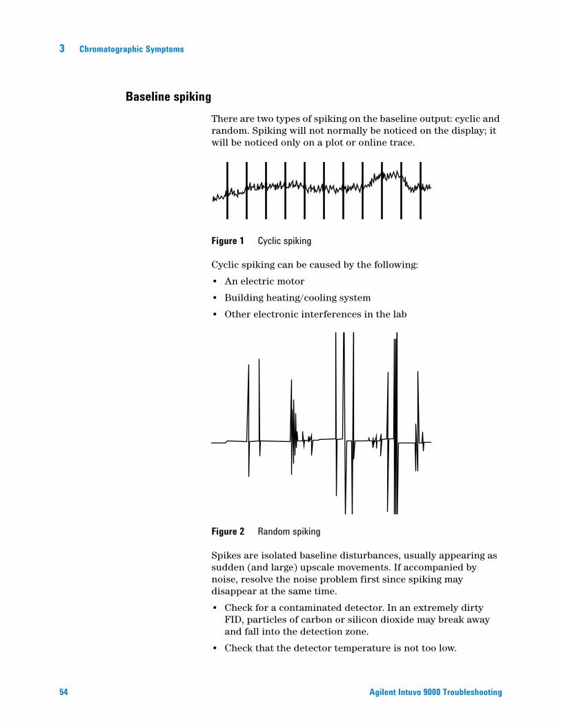
There are two types of spiking on the baseline output: cyclic and random. Spiking will not normally be noticed on the display; it will be noticed only on a plot or online trace.
Figure 1 Cyclic spiking
Cyclic spiking can be caused by the following:
• An electric motor
• Building heating/cooling system
• Other electronic interferences in the lab
Figure 2 Random spiking
Spikes are isolated baseline disturbances, usually appearing as sudden (and large) upscale movements. If accompanied by noise, resolve the noise problem first since spiking may disappear at the same time.
• Check for a contaminated detector. In an extremely dirty FID, particles of carbon or silicon dioxide may break away and fall into the detection zone.
• Check that the detector temperature is not too low.
Agilent Intuvo 9000 Troubleshooting
Chromatographic Symptoms 3
Low Peak Area or Height (Low Sensitivity)
Agilent Intuvo 9000 Troubleshooting
• If using an inlet in split mode, check the split ratio.
• Check for leaks.
• Check the inlet for contamination. (See “Contamination or Carryover”.)
• Verify that the liner type is appropriate for the sample.
• Verify that the detector flow settings are correct.
Measure the actual detector flows. If an actual flow does not match the GC display, check for contamination and restrictions, for example a plugged jet. See the following:
• To Measure a Detector Flow
• To Check for a Plugged FID Jet
• To Check for a Plugged NPD Jet
• Check the supply gas purity.
• Check all trap indicators and dates.
• Verify that the method parameters are correct.
• Some samples change with heat or ultraviolet light. Check sample stability.
• Check configured syringe size. Some syringe sizes are specified at half-capacity. If the maximum syringe volume is marked at half-height on the barrel, not at the top of the barrel, enter twice the labeled volume when configuring the syringe size.
• If the drop in peak area or height happened gradually due to baseline rise, rather than a sudden change, check for detector contamination. Bakeout the detector.
If using an FID:
• Check for a dirty jet.
• Check for contaminated detector parts.
• To Check for a Plugged FID Jet
If using an NPD:
• Check the detector for contamination.
• Replace ceramic insulators.
• Replace the bead.
If using an FPD+:
• Check that the correct filter is installed and is clean.
55
56
3 Chromatographic Symptoms
• Check the flow rates.
• Check the makeup gas type.
To Resolve Low Sensitivity with an FID
In normal use, the FID can develop deposits on the collector, insulators, jet, and so forth. To reduce contamination buildup, Agilent recommends using the detector at 300 °C or higher. However, even with normal use deposits develop in the jet (usually white silica from column bleed or black, carbonaceous soot). These deposits reduce sensitivity and cause chromatographic noise and spikes. Jets require periodic cleaning or replacement. The following procedure checks for causes of low sensitivity by frequency of occurrence.For sensitivity loss associated with noise, wander, or drift, also see “Noisy Detector, Including Wander, Drift, and Baseline Spikes”.
1 Check detector flow settings.
The general rule is 1:1 flow ratio of hydrogen to (column + makeup gas).
2 Measure the actual detector flow rates. See “To Measure a Detector Flow”. If the actual hydrogen, makeup, and capillary column flows are lower than the display, the jet is becoming plugged. See “To Check for a Plugged FID Jet”. Replace the jet.
3 Check inlet parameters that control venting, such as split ratio and splitless purge delay time. Make sure the sample is not being inadvertently vented.
4 Perform inlet maintenance (replace all consumable parts) and pressure test the inlet when completed.
5 Perform complete FID maintenance. Disassemble the FID and clean or replace all parts.
Agilent Intuvo 9000 Troubleshooting
Chromatographic Symptoms 3
FID Flame Goes Out During a Run and Attempts to Reignite
Agilent Intuvo 9000 Troubleshooting
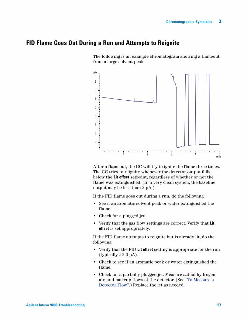
The following is an example chromatogram showing a flameout from a large solvent peak.
After a flameout, the GC will try to ignite the flame three times. The GC tries to reignite whenever the detector output falls below the Lit offset setpoint, regardless of whether or not the flame was extinguished. (In a very clean system, the baseline output may be less than 2 pA.)
If the FID flame goes out during a run, do the following:
• See if an aromatic solvent peak or water extinguished the flame.
• Check for a plugged jet.
• Verify that the gas flow settings are correct. Verify that Lit offset is set appropriately.
If the FID flame attempts to reignite but is already lit, do the following:
• Verify that the FID Lit offset setting is appropriate for the run (typically 2.0 pA).
• Check to see if an aromatic peak or water extinguished the flame.
• Check for a partially plugged jet. Measure actual hydrogen, air, and makeup flows at the detector. (See “To Measure a Detector Flow”.) Replace the jet as needed.
9
8
7
6
5
4
3
2
1 2 3 4 5min
pA
57

58
3 Chromatographic Symptoms
• Check that column is properly installed.
• Check for leaks.
Agilent Intuvo 9000 Troubleshooting
Chromatographic Symptoms 3
FID Baseline Output Above 20 pA
Agilent Intuvo 9000 Troubleshooting
• Verify the purity of the carrier and detector gas supply. See the Agilent Intuvo 9000 GC, GC/MS, and ALS Site Preparation Guide.
• Inspect the column for column bleed. Lower the oven temperature to ambient. If the detector output drops significantly, suspect a contaminated or bleeding column or contaminated carrier gas. Confirm column bleed by turning off column flow (with oven cool) and checking the detector output.
• Check the gas supply trap indicators/dates and ensure that the traps are not expended.
• Verify that the detector was reassembled properly after recent maintenance.
• Inspect the detector for contamination. Bake out the detector.
• Check that the FID leakage current is < 2.0 pA. (See “To Measure FID Leakage Current”.)
59
3 Chromatographic Symptoms
FID Baseline Output at Maximum (~8 Million)
60
If the FID output seems to be stuck at a very high value (up to 8 million counts), check for a shorted collector.
1 Check if the interconnect spring has been bent. Remove the collector assembly and visually inspect the spring.
2 Disassemble the collector assembly and visually check for rust buildup on any parts. Replace parts as needed. To avoid this problem, operate the detector at >300 °C.
3 Check for carbonization in the detector due to injection or aromatic or chlorinated solvents. To avoid this problem, operate the detector at >300 °C. Reassemble and install the collector and operate the detector using higher air and hydrogen flows (air must be 450 mL/min, hydrogen at 35 mL/min).
Agilent Intuvo 9000 Troubleshooting
Chromatographic Symptoms 3
FPD+ Flame Goes Out During a Run and Attempts to Reignite
Agilent Intuvo 9000 Troubleshooting
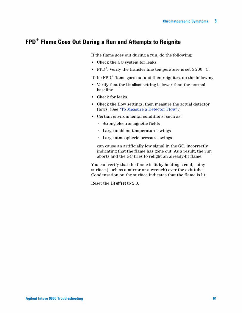
If the flame goes out during a run, do the following:
• Check the GC system for leaks.
• FPD+: Verify the transfer line temperature is set 200 °C.
If the FPD+ flame goes out and then reignites, do the following:
• Verify that the Lit offset setting is lower than the normal baseline.
• Check for leaks.
• Check the flow settings, then measure the actual detector flows. (See “To Measure a Detector Flow”.)
• Certain environmental conditions, such as:
• Strong electromagnetic fields
• Large ambient temperature swings
• Large atmospheric pressure swings
can cause an artificially low signal in the GC, incorrectly indicating that the flame has gone out. As a result, the run aborts and the GC tries to relight an already-lit flame.
You can verify that the flame is lit by holding a cold, shiny surface (such as a mirror or a wrench) over the exit tube. Condensation on the surface indicates that the flame is lit.
Reset the Lit offset to 2.0.
61

3 Chromatographic Symptoms
FPD+ Quenching/Repeatability
62
Hydrocarbon quenching occurs when a high concentration of carbon dioxide from a hydrocarbon peak is in the flame at the same time as the sulfur species. Part of the light emitted by the sulfur species is absorbed by some CO2 species.
Self-quenching occurs at high concentrations of the heteroatom species. Some other ground state (inactivated) species reabsorbs the emitted photon, preventing it from reaching the PMT.
To resolve hydrocarbon quenching:
• The column should provide good separation of the compounds, those that contain sulfur or phosphorus as well as those that do not but may absorb light.
• Optimize the chromatographic separation such that hydrocarbon peaks are resolved from sulfur or phosphorus peaks.
1 Run the analysis first on a FID in order to see all the peaks (the FPD+ ignores hydrocarbons).
2 Run the analysis on the FPD+.
3 Modify the method so that the peak of interest is separate from the rest of the peaks.
Agilent Intuvo 9000 Troubleshooting
Chromatographic Symptoms 3
FPD+ Output Too High or Too Low
Agilent Intuvo 9000 Troubleshooting
• Verify that the correct filter is being used. Do not use a phosphorus filter with sulfur-optimized flows or a sulfur filter with phosphorus-optimized flows.
• Check the position of the column as installed in the detector.
• Check the gas purity.
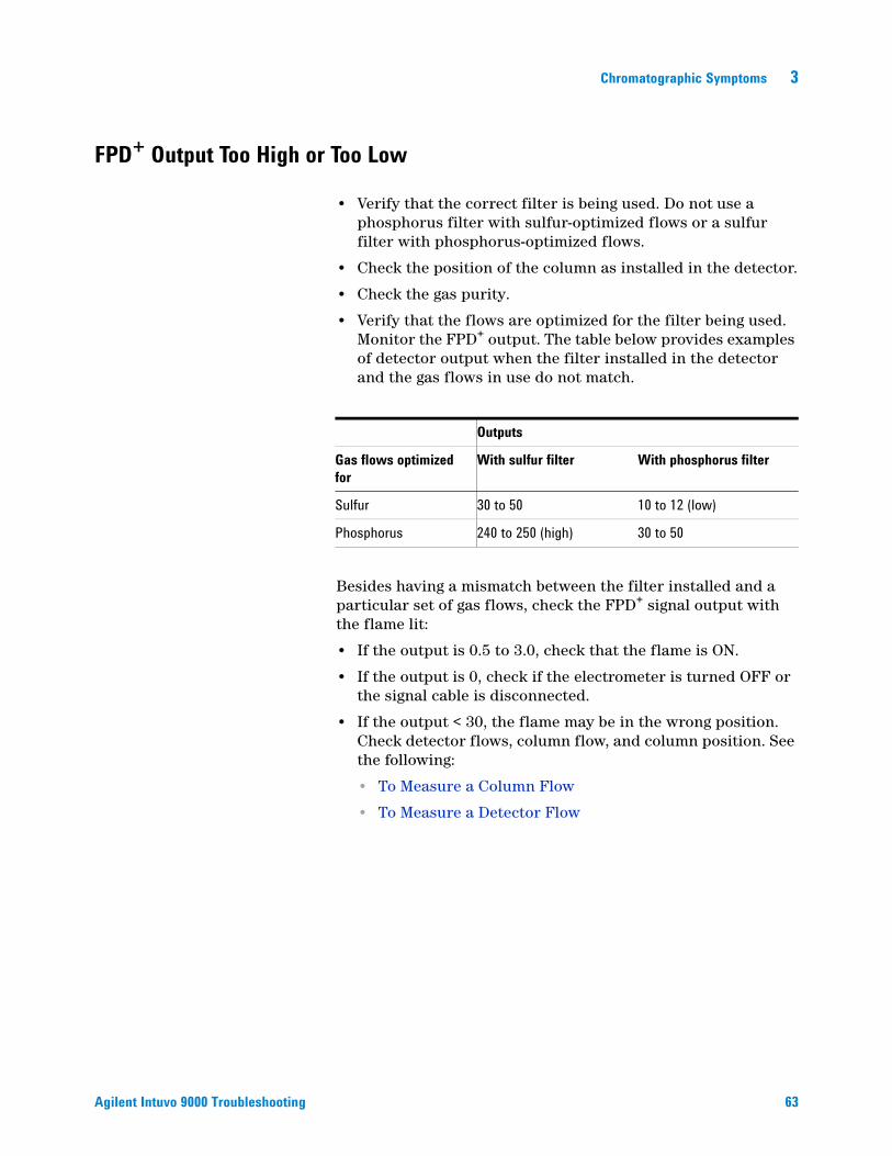
• Verify that the flows are optimized for the filter being used. Monitor the FPD+ output. The table below provides examples of detector output when the filter installed in the detector and the gas flows in use do not match.
Besides having a mismatch between the filter installed and a particular set of gas flows, check the FPD+ signal output with the flame lit:
• If the output is 0.5 to 3.0, check that the flame is ON.
• If the output is 0, check if the electrometer is turned OFF or the signal cable is disconnected.
• If the output < 30, the flame may be in the wrong position. Check detector flows, column flow, and column position. See the following:
• To Measure a Column Flow
• To Measure a Detector Flow
Outputs
Gas flows optimized for
With sulfur filter With phosphorus filter
Sulfur 30 to 50 10 to 12 (low)
Phosphorus 240 to 250 (high) 30 to 50
63

3 Chromatographic Symptoms
FPD+ Low Peak Areas
64
• Check the flow settings, then measure the actual detector flows. (See “To Measure a Detector Flow”.)
• Perform complete inlet maintenance: Replace all consumable parts and bake out the inlet.
• Consider the filter type (sulfur or phosphorus).
• Check the system for leaks.
• Verify that the method settings are appropriate.
• Check the flow rates.
• Check the makeup gas type.
Agilent Intuvo 9000 Troubleshooting

Chromatographic Symptoms 3
FPD+ Large Peak Width at Half-Height
Agilent Intuvo 9000 Troubleshooting
If the FPD+ produces peaks that are abnormally wide at half the peak height, do the following:
• Check the actual injection volume; reduce if necessary.
• Verify that the liner is not reacting with the sample.
65

3 Chromatographic Symptoms
FPD+ Baseline Output High, > 20 pA
66
• Check the supply gas purity.
• Check all trap indicators and dates.
• Check the detector for contamination.
• Check for light leaks at the photomultiplier tube (PMT); tighten the PMT if it is loose.
• Perform complete inlet maintenance: Replace all consumable parts and bake out the inlet.
• Perform column maintenance: Bake out contaminants as needed.
Agilent Intuvo 9000 Troubleshooting
Chromatographic Symptoms 3
NPD Solvent Quenching
Agilent Intuvo 9000 Troubleshooting
If the baseline does not recover after a solvent peak, try the following:
• Turn hydrogen off/on around the solvent peak.
• Use nitrogen as the makeup gas.
• Set the total column flow and makeup gas to less than 10 mL/min.
• Increase the air flow by 10 mL/min.
• Increase the detector temperature to 325 °C.
67

3 Chromatographic Symptoms
NPD Response Low
68
• Perform complete inlet maintenance: Replace all consumable parts and bake out the inlet.
• Perform column maintenance: Bake out contaminants as needed.
• A large concentration of solvent has extinguished the hydrogen/air plasma. Increase the bead voltage. Run the makeup gas at a flow rate of 5 mL/min.
• Verify that there is hydrogen coming from the external supply. Check that flow and pressure are turned on at the keyboard. The hydrogen flow rate should be between 1.0 and 5.5 mL/min. Measure the actual gas flow at the detector. (See “To Measure a Detector Flow”.)
• Check for a partially plugged jet. See To Check for a Plugged FID Jet.
• If the upper ceramic insulator is contaminated, a high offset (2 to 15 pA or more) will occur when the bead is off. This directly affects sensitivity. Replace the ceramic insulator.
Agilent Intuvo 9000 Troubleshooting

Chromatographic Symptoms 3
Agilent Intuvo 9000 Troubleshooting
• Verify that the bead is activated. Look through the vent hole on the detector lid to see if the bead is glowing orange. If the bead is not glowing, check the detector background signal. Reduce the bead voltage to zero to establish a reference level, and then look for a sudden sharp increase in output as the bead voltage increases, which indicates that ignition occurred. If 4 V are being supplied to the bead but it is not igniting, the bead is probably burned out. Replace the bead.
• Replace the insulators/collector.
• Check for liquid phase contamination (polar phases).
69
3 Chromatographic Symptoms
NPD Baseline Output > 8 million
70
• The collector is shorted to the detector housing. Disassemble the collector and insulators and reinstall.
Agilent Intuvo 9000 Troubleshooting
Chromatographic Symptoms 3
NPD Adjust Offset Process Not Functioning Properly
Agilent Intuvo 9000 Troubleshooting
• Inspect the jet to see if it is clogged. (See To Check for a Plugged NPD Jet.)
• Measure the actual detector flows. (See To Measure a Detector Flow.) If the hydrogen or makeup flows are zero or much lower than the displayed flow, suspect a plugged jet.
• Check the condition of the bead. Replace if necessary.
• Verify that the flow settings are correct.
• If the process still fails, there could be a large leak in the system. This causes measured flow rates to be different from actual flow rates. Thoroughly leak check the whole system.
• Set the equilibration time to 0.0.
71

3 Chromatographic Symptoms
NPD Low Selectivity
72
(High hydrocarbon response relative to nitrogen or phosphorus.)
• Verify that the hydrogen flow is correct (< 3 mL/min).
• Inspect the bead; it may be defective or expended.
• Verify correct bead voltage.
• Replace the collector and insulators.
Agilent Intuvo 9000 Troubleshooting

Chromatographic Symptoms 3
Negative Peaks Seen with TCD
Agilent Intuvo 9000 Troubleshooting
• Verify that the correct gas type is being used.
• Check for a leak in the system.
• Consider thermal conductivity of analytes relative to carrier.
• Check the flow settings, then measure the actual detector flows. (See “To Measure a Detector Flow”.)
73

3 Chromatographic Symptoms
TCD Baseline Has Dampened Sinusoidal Noise Trailing Peaks (Ringing Baseline)
74
Wrong data rate is selected in the data system. For TCD, the data rate should be 5 Hz.
Agilent Intuvo 9000 Troubleshooting
Chromatographic Symptoms 3
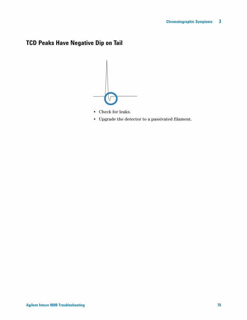
TCD Peaks Have Negative Dip on Tail
Agilent Intuvo 9000 Troubleshooting
• Check for leaks.
• Upgrade the detector to a passivated filament.
75

3 Chromatographic Symptoms
76 Agilent Intuvo 9000 Troubleshooting

Agilent Intuvo 9000 Gas ChromatographTroubleshooting
4GC Not Ready SymptomsGC Never Becomes Ready 78Flow Never Becomes Ready 79Cannot Set a Flow or Pressure 80A Gas Does Not Reach Setpoint Pressure or Flow 81A Gas Exceeds Pressure Setpoint or Flow 82The Inlet Pressure or Flow Fluctuates 83Cannot Maintain a Pressure as Low as the Setpoint on a Split Inlet 84The Measured Column Flow Does Not Equal the Displayed Flow 85FID Does Not Ignite 86FID Ignitor Does Not Glow During Injection Sequence 87FID or NPD Measured Hydrogen and Makeup Gas Flows Much Less Than Setpoint 89NPD Adjust Offset Process Fails 90FPD+ Does Not Ignite 91Valve Not Ready 93Blinking Not Ready Light: Detector Hardware Fault/TCD Filament Voltage 94
This section includes faults and symptoms that will occur when the GC is on but cannot perform analyses. This is indicated by a “Not Ready” warning, by fault messages, or by other symptoms.
77Agilent Technologies

4 GC Not Ready Symptoms
GC Never Becomes Ready
78
Normally the GC becomes ready after flows and temperatures reach setpoint. If the GC does not become ready after a long period of time:
• Check for a sampler problem.
• Check for a data system problem.
• If performing manual injections in splitless or gas-saver mode, you may need to prepare the inlet for the injection. Do this, for example:
• To toggle the inlet purge valve before a splitless injection
• To prepare for a pulsed injection
• To turn off gas saver.
Agilent Intuvo 9000 Troubleshooting

GC Not Ready Symptoms 4
Flow Never Becomes Ready
Agilent Intuvo 9000 Troubleshooting
If the gas flow never becomes ready, check for the following:
• Check the supply gas for sufficient delivery pressure.
• Check the configured gas type. The configured gas type must match the actual gas plumbed to the GC.
• Check for leaks in the gas delivery plumbing and the GC.
79
4 GC Not Ready Symptoms
Cannot Set a Flow or Pressure
80
If you cannot set a flow or pressure using the split/splitless or MMI inlets, do the following:
• Check the column mode.
• Check that a capillary column is configured to the correct inlet.
• Check that the flow is turned on.
Agilent Intuvo 9000 Troubleshooting
GC Not Ready Symptoms 4
A Gas Does Not Reach Setpoint Pressure or Flow
Agilent Intuvo 9000 Troubleshooting
If an inlet does not reach its pressure setpoint, it will shut down in an amount of time determined by the type of inlet. Do the following:
• Check for sufficient gas supply delivery pressure. The pressure at the supply should be at least 10 psi greater than the desired setpoint.
• Check for leaks. A large leak may be present somewhere in the system. Use an electronic leak detector to find leaks, then correct them. Do not forget to check the column—a broken column is a very large leak.
• If using gas saver, be sure that the gas saver flow rate is high enough to maintain the highest column-head pressure used during a run.
• Check for a defective inlet or detector pressure sensor.
If you are using a split/splitless inlet, MMI inlet:
• Check the split ratio. Increase the amount of split flow.
81
4 GC Not Ready Symptoms
A Gas Exceeds Pressure Setpoint or Flow
82
If a gas exceeds its pressure or flow setpoint, do the following:
If using a split/splitless inlet or MMI inlet:
• Decrease the split ratio.
• Replace the split vent filter.
• Check the split vent trap line for contamination or an abnormal restriction. Run the split vent restriction test. See:
• Verify that the correct liner is selected.
• Verify the method pressure settings for the SS inlet are above the minimum viable settings available on the GC. See Table 3.
If using an FID or NPD:
• Check for a plugged jet. See “To Check for a Plugged FID Jet” or “To Check for a Plugged NPD Jet”.
Valves:
• Check for a misaligned rotor.
Agilent Intuvo 9000 Troubleshooting
GC Not Ready Symptoms 4
The Inlet Pressure or Flow Fluctuates
Agilent Intuvo 9000 Troubleshooting
A fluctuation in inlet pressure causes variations in the flow rate and retention times during a run. Do the following:
• Check if the gas purifier or gas generator is operating at or near capacity.
• Check the supply gas for sufficient delivery pressure.
• Verify that the supply pressure regulator is functioning properly. Systems with long supply tubing lengths may require a step-down regulator near the GC. Also, use an additional regulator to smooth out fluctuations caused by gas generators.
• Check for leaks. A large leak may be present somewhere in the system. Use an electronic leak detector to find leaks, then correct them. Do not forget to check the column—a broken column is a very large leak.
• Check for large restrictions in the inlet liner or split vent trap.
• Verify that the correct liner is installed. Some liners have large pressure drops caused by design or tight packaging.
• Check for extreme changes in room temperature during runs. Correct laboratory temperature problem or move the instrument to a more suitable location.
• Verify Auto Flow Zero feature is On.
83
4 GC Not Ready Symptoms
Cannot Maintain a Pressure as Low as the Setpoint on a Split Inlet
84
If the GC cannot maintain a pressure as low as the setpoint, check for the following:
• Consider using a liner designed for split analysis.
• Method pressure parameter (or resultant pressure from a flow setting) is too low for the carrier gas type.
• Check for a plugged liner.
• Check for contamination or restriction in the split vent line.
• Replace the guard chip or jumper chip.
Agilent Intuvo 9000 Troubleshooting
GC Not Ready Symptoms 4
The Measured Column Flow Does Not Equal the Displayed Flow
Agilent Intuvo 9000 Troubleshooting
If the actual column flow does not match the calculated flow displayed on the GC within 10%, do the following:
• Verify that the measured flows are corrected to 25 °C and 1 atmosphere.
• Verify that the correct column dimensions are configured accurately.
• A short (<15 m) 0.58 to 0.75 mm id WCOT column is being used with a split/splitless capillary inlet. The total flow controller is set for a high flow rate, which creates some pressure in the inlet and causes column flow even with a setpoint pressure of zero. (In these situations, an actual pressure may be shown on the display, even with a zero setpoint.) With short, 530 to 750 mm columns, keep the total flow rate as low as possible (for example, 20 to 30 mL/min). Install a longer column with higher resistance (for example, 15 to 30 m).
• The split vent line or trap may be partly plugged, creating an actual inlet pressure higher than the setpoint pressure. Check for a restriction in the split vent line.
• Make sure that the auto flow zero is turned on. As applicable, zero the flow and pressure sensor for the flow module. If this does not solve the problem, replace the flow module.
85

4 GC Not Ready Symptoms
FID Does Not Ignite
86
• Verify that the Lit Offset is 2.0 pA.
• Ensure that the FID temperature is high enough for ignition (>150 °C). Agilent recommends >300 °C.
• Check that the FID ignitor glows during ignition sequence. (See To Verify FID Ignitor Function During Ignition Sequence.)
• Check that the air and hydrogen pressures meet Agilent’s recommendations (hydrogen > 35 psi [210 kPa] and air > 55 psi [380 kPa]). See the Agilent Intuvo 9000 GC, GC/MS, and ALS Site Preparation Guide.
• Try increasing the supply pressures to the FID flow module. This makes the flame easier to light without changing the setpoints.
• Increase hydrogen flow and decrease or turn off makeup gas flow until ignition occurs, then reduce them toward the method values. Experiment for the best values.
Increasing hydrogen flow and decreasing makeup flow will help the FID ignite more easily. If it will light under these modified conditions, the cause could be a partially clogged jet or a weak ignitor.
• Check for a plugged or partially plugged jet. (See To Check for a Plugged FID Jet.)
• Measure the FID flow rates. Actual flow rates should be within +/-10% of the setpoint. The hydrogen:air ratio greatly impacts ignition. Nonoptimal flow settings can prevent flame ignition. (See To Measure a Detector Flow.)
• Check the column flow rate. (See To Measure a Column Flow.) Hydrogen flow should be greater than the sum of the column flow and makeup flow.
• If the analysis permits, substitute nitrogen for helium as makeup.
Agilent Intuvo 9000 Troubleshooting
GC Not Ready Symptoms 4
FID Ignitor Does Not Glow During Injection Sequence
Agilent Intuvo 9000 Troubleshooting
WARNING Keep body parts at a safe distance from the FID chimney while performing this task. If using hydrogen, the FID flame will not be visible.
1 Remove the detector top cover.
2 Turn the FID flame On.3 Observe the ignitor plug though the FID chimney. The small
hole should glow during ignition sequence.
If the test fails, check for the following possible causes:
• The ignitor may be bad; replace the ignitor.
• Detector temperature is set to < 150 °C. Agilent recommends operating the FID at > 300 °C.
• The ignitor is not making a good connection to the ground:
• The ignitor must be tightly screwed into the FID castle assembly.
• The three T-20 Torx screws that hold the collector assembly in place must be tight.
• The brass knurled nut that holds the FID castle assembly in place must be tight.
87

88
4 GC Not Ready Symptoms
Perform FID maintenance if these parts are corroded or oxidized.
T-20 Torx screws (3)
Ignitor
Knurled nut
Agilent Intuvo 9000 Troubleshooting

GC Not Ready Symptoms 4
FID or NPD Measured Hydrogen and Makeup Gas Flows Much Less Than Setpoint
Agilent Intuvo 9000 Troubleshooting
• Check for a clogged or partially clogged jet. A clogged jet creates backpressure. Since the flow module uses pressure control, the increased backpressure simulates proper flow. The actual flow rate will drop but the GC remains functional. See:
“To Check for a Plugged FID Jet”
“To Check for a Plugged NPD Jet”
89

4 GC Not Ready Symptoms
NPD Adjust Offset Process Fails
90
• Inspect the jet to see if it is clogged. (See To Check for a Plugged NPD Jet.)
• Measure the actual detector flows. (See To Measure a Detector Flow.) If the hydrogen or makeup flows are zero or much lower than the displayed flow, suspect a plugged jet.
• Check the condition of the bead. Replace if necessary.
• Verify that the flow settings are correct.
• If the process still fails, there could be a large leak in the system. This causes measured flow rates to be different from actual flow rates. Thoroughly leak check the whole system.
• Set the equilibration time to 0.0.
Agilent Intuvo 9000 Troubleshooting
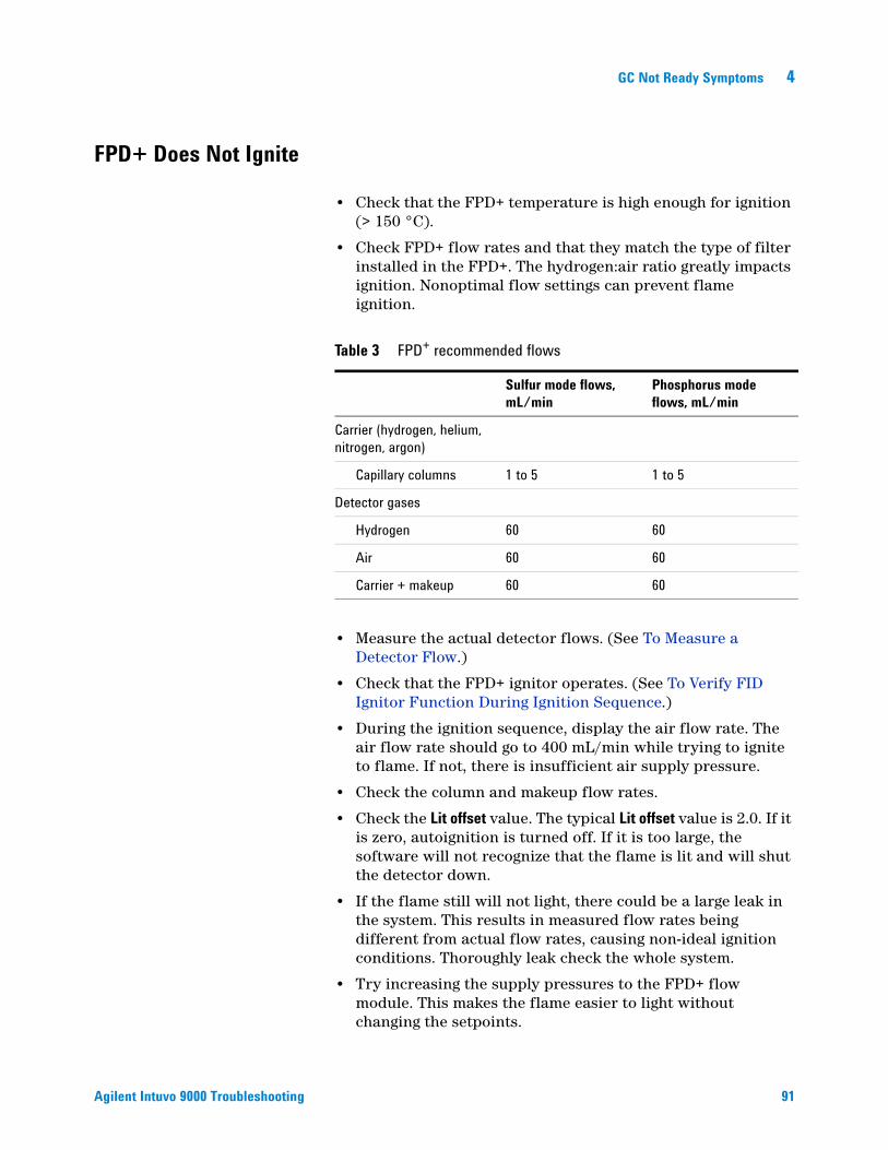
GC Not Ready Symptoms 4
FPD+ Does Not Ignite
Agilent Intuvo 9000 Troubleshooting
• Check that the FPD+ temperature is high enough for ignition (> 150 °C).
• Check FPD+ flow rates and that they match the type of filter installed in the FPD+. The hydrogen:air ratio greatly impacts ignition. Nonoptimal flow settings can prevent flame ignition.
• Measure the actual detector flows. (See To Measure a Detector Flow.)
• Check that the FPD+ ignitor operates. (See To Verify FID Ignitor Function During Ignition Sequence.)
• During the ignition sequence, display the air flow rate. The air flow rate should go to 400 mL/min while trying to ignite to flame. If not, there is insufficient air supply pressure.
• Check the column and makeup flow rates.
• Check the Lit offset value. The typical Lit offset value is 2.0. If it is zero, autoignition is turned off. If it is too large, the software will not recognize that the flame is lit and will shut the detector down.
• If the flame still will not light, there could be a large leak in the system. This results in measured flow rates being different from actual flow rates, causing non-ideal ignition conditions. Thoroughly leak check the whole system.
• Try increasing the supply pressures to the FPD+ flow module. This makes the flame easier to light without changing the setpoints.
Table 3 FPD+ recommended flows
Sulfur mode flows,mL/min
Phosphorus mode flows, mL/min
Carrier (hydrogen, helium,nitrogen, argon)
Capillary columns 1 to 5 1 to 5
Detector gases
Hydrogen 60 60
Air 60 60
Carrier + makeup 60 60
91
92
4 GC Not Ready Symptoms
• Under some operating conditions, the flame will light more easily with the vent tube removed. After lighting the flame, reinstall the vent tube.
• Try changing to the phosphorus mode flows, lighting the flame, and gradually alter the flows to the sulfur values.
• Check cable connections to coupling, coupling connection to glow plug, tight glow plug.
Agilent Intuvo 9000 Troubleshooting
GC Not Ready Symptoms 4
Valve Not Ready
Agilent Intuvo 9000 Troubleshooting
Troubleshooting depends on the type of valve.
Gas sampling valves
The GC is normally not ready whenever the inject time or load time has not elapsed. It becomes ready when the specified load or inject time has passed.93
4 GC Not Ready Symptoms
Blinking Not Ready Light: Detector Hardware Fault/TCD Filament Voltage
94
If the TCD filament is open, the Not Ready LED blinks and the GC will not become Ready.
Agilent Intuvo 9000 Troubleshooting

Agilent Intuvo 9000 Gas ChromatographTroubleshooting
5Shutdown SymptomsColumn Shutdowns 96Hydrogen Shutdowns 97Detector Air Shutdowns 999000 MS Shutdown 100Thermal Shutdowns 102
95Agilent Technologies
5 Shutdown Symptoms
Column Shutdowns
96
The GC monitors inlet and auxiliary gas streams. If a carrier gas (which can include an auxiliary flow module or pneumatics control module) is unable to reach its flow or pressure setpoint, the GC assumes that a leak exists. It will warn you with a beep after 25 seconds, and it will continue to beep in intervals. After about 5 minutes, the GC will shut down components to create a safe state. The GC:
• Displays Front inlet pressure shutdown.
• Turns off to avoid column damage.
• Flashes oven temperature setpoint Off.• Turns off all flows for the column. When viewed, their
parameters flash Off. For example, the septum purge and column flows for a split/splitless inlet would turn off.
• Turns off all other heaters. When viewed, their temperature parameters flash Off.
• Attempts to turn on a shut-down zone fail with an error message.
• Turns off the TCD filament.
• Turns off the FID or FPD+ ignitor, and the air and fuel gas flows.
• Turns off the NPD bead, and air and fuel gas flows.
• Communicates with the configured MS, if present, so the MS can react to the shutdown event.
To recover from this state.
1 Fix the cause of the shutdown. Verify the carrier gas supply. The GC requires a delivered gas pressure of 70 kPa (10 psi) higher than the highest pressure used in the run. See the Agilent Intuvo 9000 GC, GC/MS, and ALS Site Preparation Guide.
• Check for a broken column.
• Check for leaks.
• Replace the inlet O-ring.
• Check the supply pressure.
2 Press the key for the device that initiated the shutdown.
Agilent Intuvo 9000 Troubleshooting

Shutdown Symptoms 5
Hydrogen Shutdowns
Agilent Intuvo 9000 Troubleshooting
Hydrogen gas may be used as a carrier or as fuel for some detectors. When mixed with air, hydrogen can form explosive mixtures.
Hydrogen used in inlets and auxiliary gas streams
The GC monitors inlet and auxiliary gas streams. If a stream is unable to reach its flow or pressure setpoint and if that stream is configured to use hydrogen, the GC assumes that a leak exists. It will warn you with a beep after 25 seconds, and it will continue to beep in intervals. After about 5 minutes, the GC will shut down components to create a safe state. The GC:• Displays Hydrogen Safety Shutdown.
• Closes the carrier supply valve to the inlet and closes and turns off both pressure and flow controls. When viewed, these parameters will flash Off.
• Opens the split vent valves in the split/splitless inlets.
• Turns off the oven heater and fan.
• Turns off all heaters (including any devices connected to the auxiliary heater controls, such as valve box heaters and transfer line heaters). When viewed, these parameters will flash Off.
• Turns off the TCD filament.
• Turns off the FID or FPD+ ignitor, and the air and fuel gas flows.
• Turns off the NPD bead, and air and fuel gas flows.
• Sounds an alarm.
• Communicates with a configured MS, if present, so the MS can react to the shutdown event.
WARNING The GC cannot detect leaks in the detector gas streams. For this reason, it is vital that the column fittings of the FID, NPD, and any other detectors that use hydrogen always be connected to a column or have a cap or plug installed and that hydrogen streams be configured so that the GC is aware of them.
97

98
5 Shutdown Symptoms
To recover from a hydrogen shutdown state:
1 Fix the cause of the shutdown:
• Replace the inlet O-ring. See the Maintenance manual.
• Check for broken column.
• Check the supply pressure. Make sure the gas supply meets the pressure recommendations listed in the Agilent Intuvo 9000 GC, GC/MS, and ALS Site Preparation Guide.
• Check the system for leaks.
2 Power cycle the GC.
3 Turn the flow back on.
Agilent Intuvo 9000 Troubleshooting
Shutdown Symptoms 5
Detector Air Shutdowns
Agilent Intuvo 9000 Troubleshooting
When air is used to combust a fuel gas (hydrogen) in a detector, an insufficient air supply will cause a shutdown for the air channel. In addition, the Air and Hydrogen flows for the associated detector will be turned Off.
To recover from this state.
1 Fix the cause of the shutdown. Verify the air supply. The FID and NPD require a delivered gas pressure of 380–690 kPa (55–100 psi). The FPD+ requires a delivered gas pressure of 690–827 kPa (100–120 psi). See the Agilent Intuvo 9000 GC, GC/MS, and ALS Site Preparation Guide.
2 Turn the flow back on.
99
5 Shutdown Symptoms
9000 MS Shutdown
100
If the 9000 receives a shutdown event from, or loses communications with, a configured MS, the GC reacts with changes such as:
• Turning off the column oven.
• Setting low pressures/flows for the MS flow path.
• Turning off hydrogen carrier gas flow, if used.
• Aborting a current run.
• Turning off the MS transfer line heater.
• Blocking all setpoint changes.
The exact changes depend on the event that triggered the shutdown. For example, the GC may react differently to a communications loss than to a failure in the MS high vacuum pump.
When troubleshooting an MSD Shutdown:
1 Check all GC, MS and data system events and logs. The GC will enter MS Shutdown if:
• The GC cannot maintain carrier flow into the MS.
• The MS reports a shutdown or fault.
• The GC and MS lose communications with each other.
2 Check the current communications status.
7000D, 7010B:
a The MS Communication setting should read Connected. If not, check the entered GC and MS IP addresses in the GC, the MS, and the PC. All GC and MS IP addresses must match in all three places.
b Check the GC and MS LAN connections. Is the LAN switch or hub operating?
5977B:
a The Lvds communication setting should read On.
b Check the GC and MS LAN connections. Is the LAN switch or hub operating?
Agilent Intuvo 9000 Troubleshooting
Shutdown Symptoms 5
Clearing an MS Shutdown
Agilent Intuvo 9000 Troubleshooting
Unlike other shutdowns, you cannot clear this state by turning off a setpoint (because setpoint changes are blocked). Instead, clear this state by disabling GC to MS communications.
If the GC started the shutdown, you can now troubleshoot the problem and resolve the GC fault.
After resolving an MS Shutdown
After resolving the GC or MS problem, always restore GC to MS communications.101

5 Shutdown Symptoms
Thermal Shutdowns
102
A thermal fault means that the oven or another heated zone is not within its allowable temperature range (lower than minimum temperature or higher than maximum temperature). Several things could cause this error:
• A problem with the electrical supply to the instrument.
• A malfunction of the zone control electronics.
• A shorted temperature sensor.
• A shorted heater.
To recover from this state:
1 Fix the cause of the shutdown:
• Check for missing insulation.
2 Most thermal shutdowns can be cleared by shutting off the thermal zone.
Agilent Intuvo 9000 Troubleshooting

Agilent Intuvo 9000 Gas ChromatographTroubleshooting
6GC Power On and Communication SymptomsGC Does Not Turn On 104PC Cannot Communicate with GC 105GC Cannot Communicate with a Configured MS or HS 106GC Does Not Recover After Firmware Update 107GC Turns On, Then Stops During Startup (During Self-Test) 108
103Agilent Technologies
6 GC Power On and Communication Symptoms
GC Does Not Turn On
104
If the GC does not turn on:
• Check the power cord.
• Check the building’s power.
• If the problem is at the GC, turn off the GC power. Wait 30 seconds, then turn the on the GC power.
Agilent Intuvo 9000 Troubleshooting
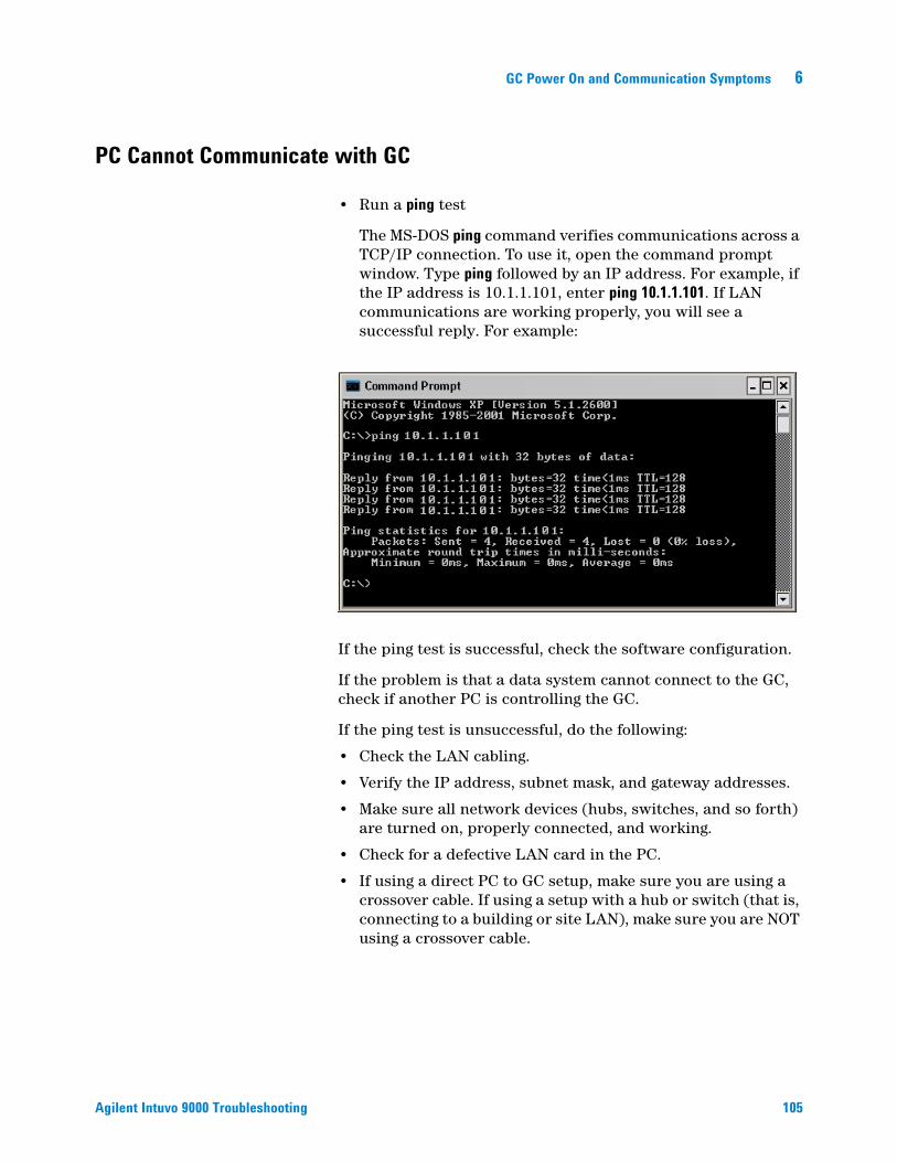
GC Power On and Communication Symptoms 6
PC Cannot Communicate with GC
Agilent Intuvo 9000 Troubleshooting
• Run a ping test
The MS-DOS ping command verifies communications across a TCP/IP connection. To use it, open the command prompt window. Type ping followed by an IP address. For example, if the IP address is 10.1.1.101, enter ping 10.1.1.101. If LAN communications are working properly, you will see a successful reply. For example:
If the ping test is successful, check the software configuration.
If the problem is that a data system cannot connect to the GC, check if another PC is controlling the GC.
If the ping test is unsuccessful, do the following:
• Check the LAN cabling.
• Verify the IP address, subnet mask, and gateway addresses.
• Make sure all network devices (hubs, switches, and so forth) are turned on, properly connected, and working.
• Check for a defective LAN card in the PC.
• If using a direct PC to GC setup, make sure you are using a crossover cable. If using a setup with a hub or switch (that is, connecting to a building or site LAN), make sure you are NOT using a crossover cable.
105

6 GC Power On and Communication Symptoms
GC Cannot Communicate with a Configured MS or HS
106
1 First, check that GC to MS (or GC to HS) communications are enabled.
2 Ping each instrument from a computer on the same local LAN. (See “PC Cannot Communicate with GC” for more information about the PC ping command.)
3 If using an Agilent data system, check the GC, HS, and MS IP addresses entered into the data system software. Again, these must exactly match the values entered into each instrument.
Agilent Intuvo 9000 Troubleshooting

GC Power On and Communication Symptoms 6
GC Does Not Recover After Firmware Update
Agilent Intuvo 9000 Troubleshooting
If the GC starts but does not display the “Power on successful” message, look for any error messages. Record any messages. Then resolve the problem as follows:
1 Try power cycling the GC.
2 If the update fails again, contact Agilent for service.
107
6 GC Power On and Communication Symptoms
GC Turns On, Then Stops During Startup (During Self-Test)
108
If the GC turns on but the normal display does not appear:
1 Turn the GC power switch Off. Wait one minute, then turn the GC power On.
2 If the GC does not return to normal, record any messages that appear on the display.
Agilent Intuvo 9000 Troubleshooting

Agilent Intuvo 9000 Gas ChromatographTroubleshooting
7Troubleshooting TasksTo Measure a Column Flow 110To Measure a Split Vent or Septum Purge Flow 114To Measure a Detector Flow 115To Perform the GC Self-Test 120To Adjust the FID Lit Offset 121To Verify That the FID Flame Is Lit 122To Verify FID Ignitor Function During Ignition Sequence 123To Measure FID Leakage Current 124To Measure FID Baseline Output 125To Isolate the Cause of FID Noise 126To Measure NPD Leakage Current 127To Check for a Plugged FID Jet 128To Check for a Plugged NPD Jet 129To Verify That the NPD Bead Is Ignited 130To Verify That the FPD+ Flame Is Lit 131When to Change Gas Purifiers 132
109Agilent Technologies

7 Troubleshooting Tasks
To Measure a Column Flow
Measuring FID, TCD, and FPD+ column flow
110
The following procedure can be used to measure column flow with an FID, TCD, and FPD+.
WARNING Hydrogen (H2) is flammable and is an explosion hazard when mixed with air in an enclosed space (for example, a flow meter). Purge flowmeters with inert gas as needed. Always measure gases individually. Always turn off detectors to prevent flame/bead autoignition.
WARNING Be careful! The detector may be hot enough to cause burns. If the detector is hot, wear heat-resistant gloves to protect your hands.
1 Gather the following:
• Appropriate flowmeter adapter tube (can be found in the GC ship kit)
• Electronic flowmeter calibrated for the gas and flow rates of concern
2 Turn off the detector.
3 Turn off the detector flows.
4 Connect the appropriate adapter to the detector exhaust.
NOTE Flowmeter tube diameters vary by model; modify the adapter to the flowmeter tubing as needed.
A 1/8-in rubber adapter tube attaches directly to a TCD exhaust vent.
A separate adapter (19301-60660) is supplied for the FID. Insert the adapter into the detector exhaust vent as far as possible. You will feel resistance as the adapter O-ring is forced into the detector exhaust vent. Twist and push the adapter during insertion to ensure a good seal.
Agilent Intuvo 9000 Troubleshooting

Troubleshooting Tasks 7
Agilent Intuvo 9000 Troubleshooting
For the FPD+, remove the plastic tubing from the FPD+ exhaust and connect the flowmeter directly to the FPD+ vent tube. If necessary, use a 1/4-inch tube adapter between the detector exhaust and the flowmeter tubing.
5 Connect the flowmeter to the flowmeter adapter to measure flow rates.
111
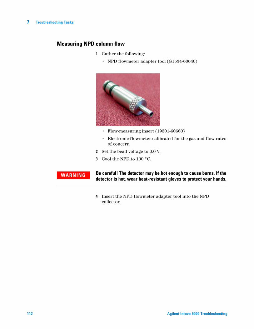
7 Troubleshooting Tasks
Measuring NPD column flow
112
1 Gather the following:
• NPD flowmeter adapter tool (G1534-60640)
• Flow-measuring insert (19301-60660)
• Electronic flowmeter calibrated for the gas and flow rates of concern
2 Set the bead voltage to 0.0 V.
3 Cool the NPD to 100 °C.
WARNING Be careful! The detector may be hot enough to cause burns. If the detector is hot, wear heat-resistant gloves to protect your hands.
4 Insert the NPD flowmeter adapter tool into the NPD collector.
Agilent Intuvo 9000 Troubleshooting

Troubleshooting Tasks 7
Agilent Intuvo 9000 Troubleshooting
5 Attach the flow-measuring insert to the NPD flowmeter adapter tool.
6 Place the flowmeter tubing over the flow-measuring insert to begin measuring flows.
113
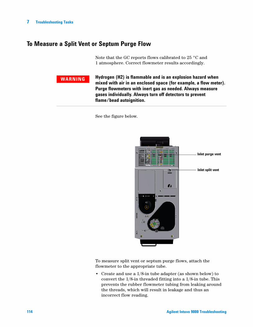
7 Troubleshooting Tasks
To Measure a Split Vent or Septum Purge Flow
114
Note that the GC reports flows calibrated to 25 °C and 1 atmosphere. Correct flowmeter results accordingly.
WARNING Hydrogen (H2) is flammable and is an explosion hazard when mixed with air in an enclosed space (for example, a flow meter). Purge flowmeters with inert gas as needed. Always measure gases individually. Always turn off detectors to prevent flame/bead autoignition.
See the figure below.
To measure split vent or septum purge flows, attach the flowmeter to the appropriate tube.
• Create and use a 1/8-in tube adapter (as shown below) to convert the 1/8-in threaded fitting into a 1/8-in tube. This prevents the rubber flowmeter tubing from leaking around the threads, which will result in leakage and thus an incorrect flow reading.
Inlet purge vent
Inlet split vent
Agilent Intuvo 90
00 Troubleshooting
Troubleshooting Tasks 7
To Measure a Detector Flow
Agilent Intuvo 9000 Troubleshooting
Detectors, especially detectors with flame, require precise flow measurements to function properly. Incorrect flows are caused by:
• Restrictions in the supply line, which will cause a Not Ready message on the GC display (all detectors)
• A leaking column or column adapter fitting (all detectors)
• A plugged jet.
• A leak in the burner chamber, window seal, or ignitor seal (FPD+)
• A pressure sensor that needs to be zeroed.
• An EPC valve that is not operating correctly.
To isolate the problem, compare the flow of one channel of gas against the actual flow rate.
Measuring FID, TCD, and FPD+ flows
WARNING Hydrogen (H2) is flammable and is an explosion hazard when mixed with air in an enclosed space (for example, a flow meter). Purge flowmeters with inert gas as needed. Always measure gases individually. Always turn off detectors to prevent flame/bead autoignition.
1 Gather the following:
• Appropriate flowmeter adapter tube (can be found in the GC ship kit)
• Electronic flowmeter calibrated for the gas and flow rates of concern
CAUTION To avoid damaging the column, cool the oven before turning off the column flow.
2 Set the oven temperature to ambient (35 °C).
3 Turn off the column flow and pressure.
4 Shut off all detector gases.
5 Turn off (where applicable): the FID flame, FPD+ flame, and TCD filament.
115
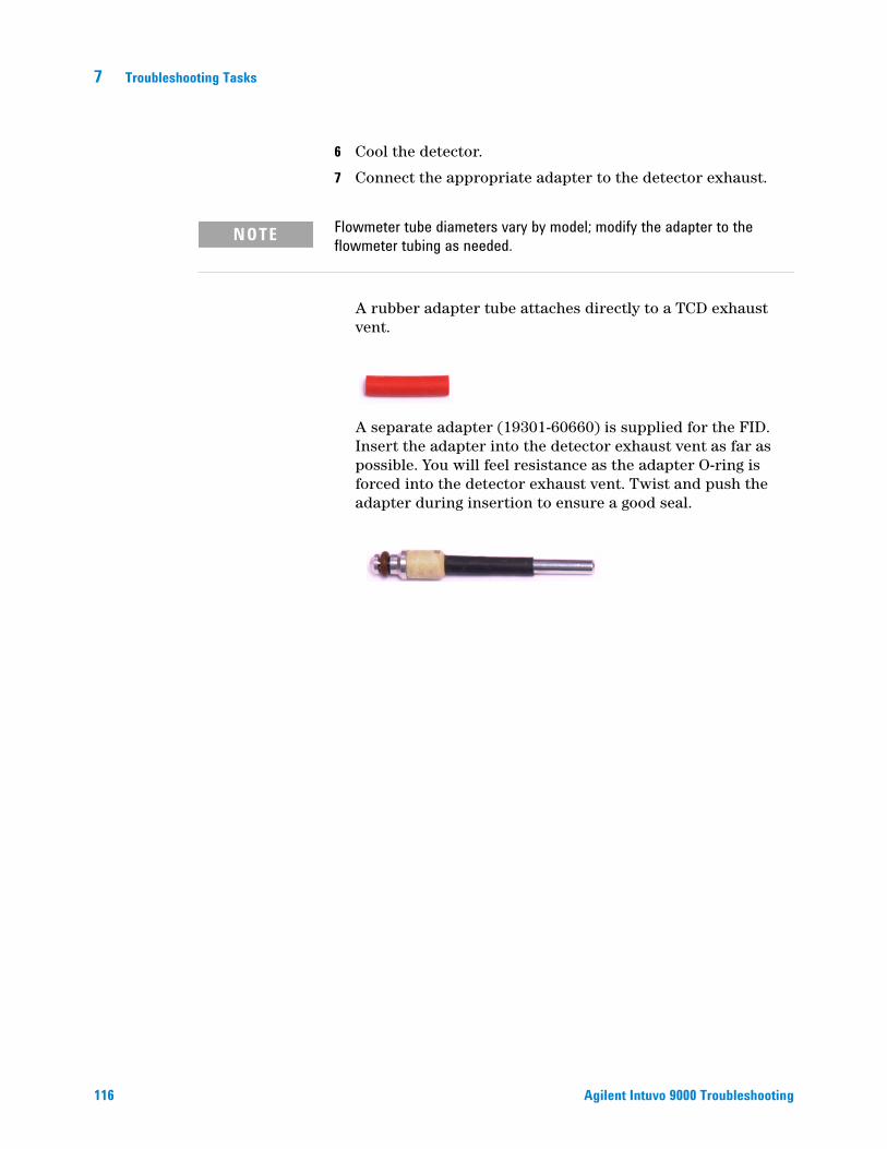
116
7 Troubleshooting Tasks
6 Cool the detector.
7 Connect the appropriate adapter to the detector exhaust.
NOTE Flowmeter tube diameters vary by model; modify the adapter to the flowmeter tubing as needed.
A rubber adapter tube attaches directly to a TCD exhaust vent.
A separate adapter (19301-60660) is supplied for the FID. Insert the adapter into the detector exhaust vent as far as possible. You will feel resistance as the adapter O-ring is forced into the detector exhaust vent. Twist and push the adapter during insertion to ensure a good seal.
Agilent Intuvo 9000 Troubleshooting
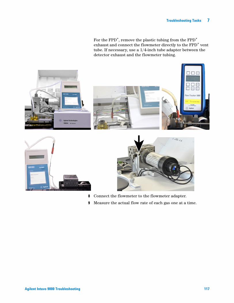
Troubleshooting Tasks 7
Agilent Intuvo 9000 Troubleshooting
For the FPD+, remove the plastic tubing from the FPD+ exhaust and connect the flowmeter directly to the FPD+ vent tube. If necessary, use a 1/4-inch tube adapter between the detector exhaust and the flowmeter tubing.
8 Connect the flowmeter to the flowmeter adapter.
9 Measure the actual flow rate of each gas one at a time.
117
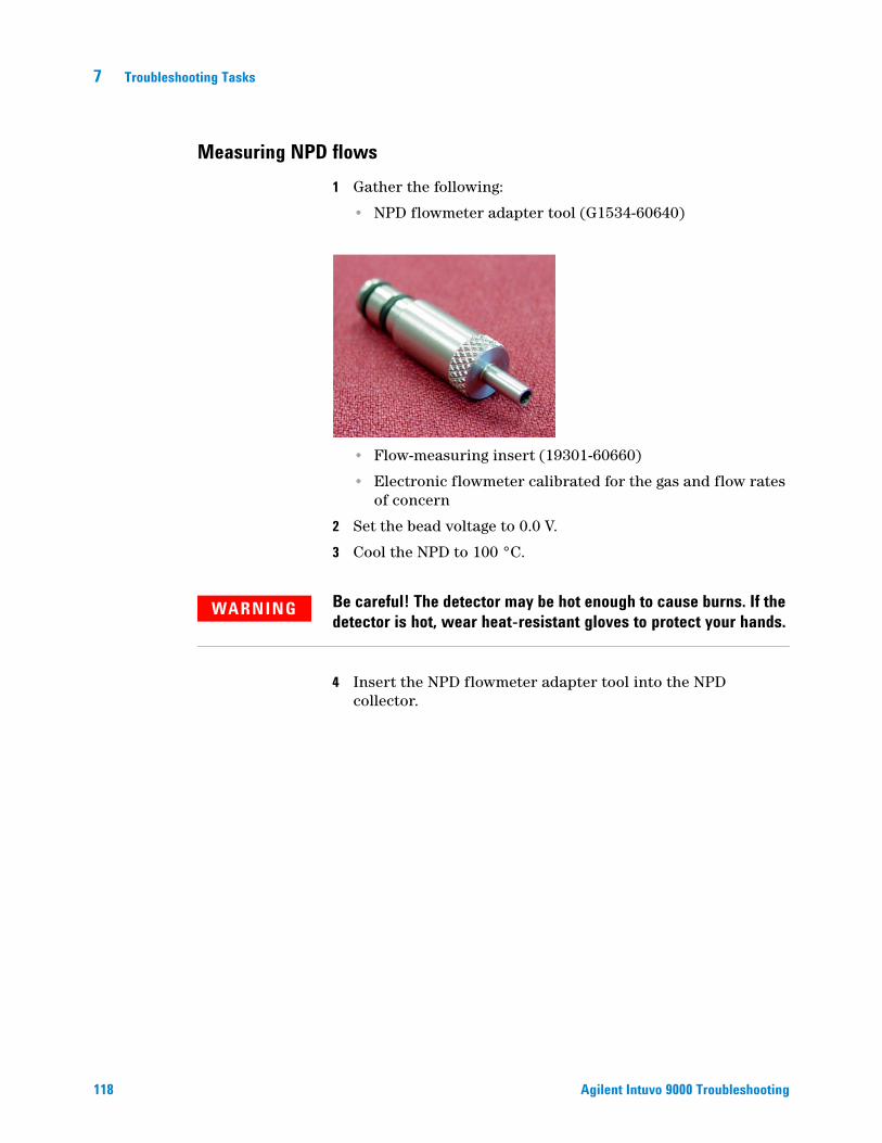
7 Troubleshooting Tasks
Measuring NPD flows
118
1 Gather the following:
• NPD flowmeter adapter tool (G1534-60640)
• Flow-measuring insert (19301-60660)
• Electronic flowmeter calibrated for the gas and flow rates of concern
2 Set the bead voltage to 0.0 V.
3 Cool the NPD to 100 °C.
WARNING Be careful! The detector may be hot enough to cause burns. If the detector is hot, wear heat-resistant gloves to protect your hands.
4 Insert the NPD flowmeter adapter tool into the NPD collector.
Agilent Intuvo 9000 Troubleshooting
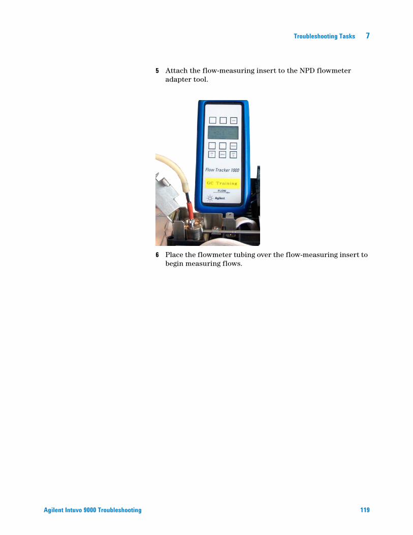
Troubleshooting Tasks 7
Agilent Intuvo 9000 Troubleshooting
5 Attach the flow-measuring insert to the NPD flowmeter adapter tool.
6 Place the flowmeter tubing over the flow-measuring insert to begin measuring flows.
119

7 Troubleshooting Tasks
To Perform the GC Self-Test
120
1 Turn the GC off.
2 Wait 1 min, then turn the GC back on. If the main GC screen appears, the GC has passed the self-test.
Agilent Intuvo 9000 Troubleshooting

Troubleshooting Tasks 7
To Adjust the FID Lit Offset
Agilent Intuvo 9000 Troubleshooting
On the GC touch screen, go to Settings > Configuration > Detector and check the lit offset.
121
7 Troubleshooting Tasks
To Verify That the FID Flame Is Lit
122
To verify that the FID flame is lit, hold a mirror or other reflective surface over the collector exhaust. Steady condensation indicates that the flame is lit.
Typically the FID output will be between 5.0 and 20.0 pA when lit and < 2.0 pA when not lit.
If the flame does not light, do the following:
• Verify that the detector temperature is above 150 °C. Agilent recommends operating the FID 300 °C.
• Verify correct detector flows.
• Inspect the jet for contamination.
• Verify that the jet is installed correctly.
• Check the column connections for leaks.
Agilent Intuvo 9000 Troubleshooting
Troubleshooting Tasks 7
To Verify FID Ignitor Function During Ignition Sequence
Agilent Intuvo 9000 Troubleshooting
WARNING Keep body parts at a safe distance from the FID chimney while performing this task. If using hydrogen, the FID flame will not be visible.
1 Remove the detector top cover.
2 Turn the FID flame On.3 Observe the ignitor plug though the FID chimney. The small
hole should glow during ignition sequence.
123
7 Troubleshooting Tasks
To Measure FID Leakage Current
124
1 Load the analytical method.
• Make sure flows are acceptable for ignition.
• Heat the detector to operating temperature or to 300 °C.
2 Turn off the FID flame.
3 Verify that the output is stable and < 1.0 pA.
If the output is unstable or > 1.0 pA, turn off the GC and check for proper assembly of the upper FID parts and for contamination.
4 Turn on the flame.
Agilent Intuvo 9000 Troubleshooting

Troubleshooting Tasks 7
To Measure FID Baseline Output
Agilent Intuvo 9000 Troubleshooting
1 With the column installed, load your checkout method.
2 Set the oven temperature to 35 °C.
3 When the flame is lit and the GC is ready, verify that the output is stable and < 20 pA (this may take some time).
4 If the output is not stable or > 20 pA, the system or gas may be contaminated.
125
7 Troubleshooting Tasks
To Isolate the Cause of FID Noise
126
FID noise is the result of mechanical, electrical and chemical factors. FID noise can be a subjective parameter. Often FID baseline noise is perceived based on history of a given detector or comparison with another detector in the lab. For proper diagnosis of noise it is important to evaluate the detector noise under documented conditions against a known standard. Find more detailed information about noise in Noisy Detector, Including Wander, Drift, and Baseline Spikes.
Before troubleshooting the detector, perform a noise test using your Agilent data system. If the detector fails the noise test, then troubleshoot the cause as described below.
To isolate the cause of FID noise:
1 If the noise test fails, remove the column and re-evaluate detector noise with the FID capped and re-ignited, using only H2/air and makeup detector gases. If it passes, suspect contaminated column/carrier gas.
2 If the noise failed with no column installed, repeat the noise test with only H2 and air - set makeup flow to "Off". If it passes, suspect contaminated makeup gas.
3 If the noise test still fails, see To Measure FID Leakage Current. If the leakage test fails, replace or clean the collector and PTFE insulators, the interconnect with spring, and/or the entire FID electrometer assembly.
4 If the leakage current test is OK, suspect a contaminated jet or contaminated H2 or Air detector gas supplies (gases, tubing, traps), especially if the background of the detector when lit is >20 pA.
Agilent Intuvo 9000 Troubleshooting
Troubleshooting Tasks 7
To Measure NPD Leakage Current
Agilent Intuvo 9000 Troubleshooting
1 Load the analytical method.
2 Set the NPD Adjust Offset to Off and the Bead Voltage to 0.00 V.
• Leave the NPD at operating temperature.
• Leave flows on or off.
3 Verify that the output (leakage current) is stable and < 1.0 pA.
4 The output should slowly drop toward 0.0 pA, and should stabilize in the tenths of a picoamp. Current > 2.0pA indicates a problem.
127
7 Troubleshooting Tasks
To Check for a Plugged FID Jet
128
The most common cause of FID ignition problems is a plugged or partially plugged jet. If the jet is not completely plugged and the flame still ignites, a secondary symptom will be lengthening peak retention times. Jet plugging is most common with thick-film/high bleed or packed columns and high temperature applications. It is best to operate the column oven within the temperature limits of the column and also to operate the FID at least 20 °C hotter than the maximum oven temperature in the GC method. If the FID jet is becoming plugged, actual H2, Makeup and Capillary carrier flows will be lower than the values indicated by the GC.
To check for a plugged FID jet:
1 Set the makeup flow to “Off”. Confirm a reading on the GC display of 0.0 mL/min for actual makeup flow.
2 Set the hydrogen flow to 75 mL/minute (increase the H2 supply pressure as needed to achieve this flow rate setting.)
3 Monitor the makeup flow “Actual” reading
If the makeup flow is indicating a value in excess of 1.0 mL/min, this indicates that the jet is plugged or partially plugged; pressure is backing up from the H2 channel into the makeup channel of the EPC module, resulting in a false flow indication on the makeup channel.
Alternately, remove the jet from the housing and hold it up to a light source. Check the holes in the jet for contamination.
Agilent Intuvo 9000 Troubleshooting

Troubleshooting Tasks 7
To Check for a Plugged NPD Jet
Agilent Intuvo 9000 Troubleshooting
The detector EPC module controls flow by maintaining a calibrated gas pressure against a fixed restriction. A plugged jet will cause inaccurate flow readings.
129

7 Troubleshooting Tasks
To Verify That the NPD Bead Is Ignited
130
WARNING Hot exhaust! Detector exhaust is hot and can cause burns.
To verify that the bead is ignited, look through the vent hole on the detector lid to see if the bead is glowing orange.
The NPD output is selected by the operator as part of the adjust offset process and generally is between 5.0 and 50.0 pA.
Agilent Intuvo 9000 Troubleshooting
Troubleshooting Tasks 7
To Verify That the FPD+ Flame Is Lit
Agilent Intuvo 9000 Troubleshooting
To verify that the FPD+ flame is lit:
1 Remove the rubber drip tube from the detector vent.
2 Hold a mirror or shiny surface near the aluminum exhaust tube. Steady condensation means that the flame is lit.
131

Agilent Technologies
When to Change Gas Purifiers
Agilent highly recommends using purifying traps in the gas lines to prevent impurities from entering and contaminating the GC system or damaging the column. Some traps are single-purpose for the removal of oxygen, moisture, or hydrocarbons, while combination traps remove all those contaminants.
The best way to know when it is time to change a trap is to use an indicating trap, which should be placed after a high capacity trap. Agilent recommends using glass indicating traps such the Gas Clean Filter system, whose clear tubes display a distinct color change in response to contamination. This color change tells the analyst it is time to change traps.
If no indicating traps are used, it is best to follow the manufacturer’s recommendation for replacement frequency. Typically, the manufacturer will state how many gas cylinders can be purified with a given trap. If desired, it is possible to estimate when to replace the trap by performing a rough calculation. For example: you have a standard “K” size cylinder with He at 99.995% purity that contains 7,800 L of He. Assuming a worst case scenario in which the remaining 0.005% is all oxygen, you should have 39 mL, or about 56 mg of O2 in the tank. Agilent’s OT3 oxygen trap, for example, has a capacity of 600 mg O2. Therefore, you need to replace the OT3 trap every 10 cylinders. This is just a rough estimate, and it is prudent to change traps too early rather than too late.
© Agilent Technologies, Inc. Printed in USA, June 2017