AERSP 301 Structural Idealization Jose Palacios July 2008.
20
AERSP 301 Structural Idealization Jose Palacios July 2008
-
date post
21-Dec-2015 -
Category
Documents
-
view
232 -
download
4
Transcript of AERSP 301 Structural Idealization Jose Palacios July 2008.

AERSP 301Structural Idealization
Jose Palacios
July 2008

Today’s LectureToday’s Lecture
• Completed– Bending of beams
– Shear of beams
– Torsion of beams
• Today– AR definition
– Combined opened & closed c/s
– Structural Idealization
*note: add general aerospace structures topic

Combined C/S’sCombined C/S’s• We looked at open and closed sections separately.
• For combined open and closed sections we can use everything we learned so far, with one exception.
– Bending – the direct stress calculations and bending deflections do not depend on the c/s type
– Shear – solve problems in the same manner. • Shear diagram
– Torsion – torisonal stiffness for closed c/s is much greater than that of an open c/s, therefore we can ignore the open c/s in the calculation of torsional stiffness.

Structural IdealizationStructural Idealization
• Consider the two-spar wing section shown. The stringers and spar carry most of the direct stresses while the skin carries the shear stresses.
• Since variation in stress over the stringer or spar flange due to bending of the wing would be small, it can be assumed to be constant.

Structural IdealizationStructural Idealization
• Stingers and spar flanges can then be replaced by concentrations of areas known as booms.
• It can be assumed that all direct stresses are carried by booms and the skin carries only shear.
• Direct stress carrying capacity of the skin may be accounted for by increasing the boom cross-section area.
Structural IdealizationStructural Idealization
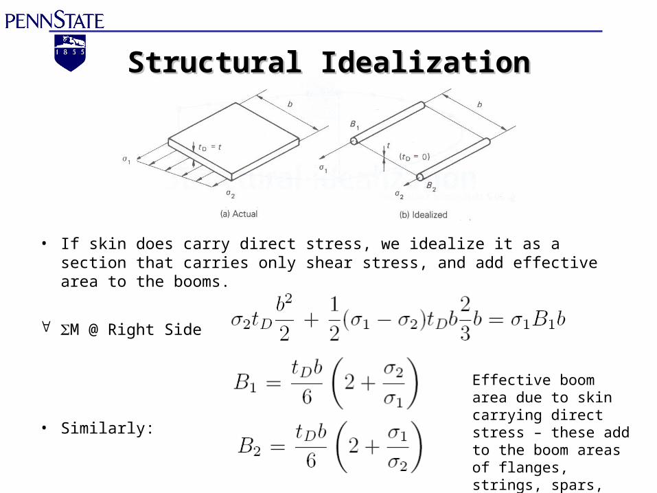
• If skin does carry direct stress, we idealize it as a section that carries only shear stress, and add effective area to the booms.
M @ Right Side
• Similarly:
Effective boom area due to skin carrying direct stress – these add to the boom areas of flanges, strings, spars, etc..

Shear of open-section beamsShear of open-section beams
• In the expression for shear flow in the cross-section:
• If we idealize skin as shown previously, then shear flow in the skin due to bending of the skin = 0.
• The above expression does not account for booms. How can we deal with booms that cause discontinuity in the skin and therefore interrupt the shear flow?
tD is the direct stress carrying thickness of the skin
tD = t, if the skin is fully effective in carrying direct stress
tD = 0, if the skin is assumed to carry only shear stress
Shear of open-section beamsShear of open-section beams
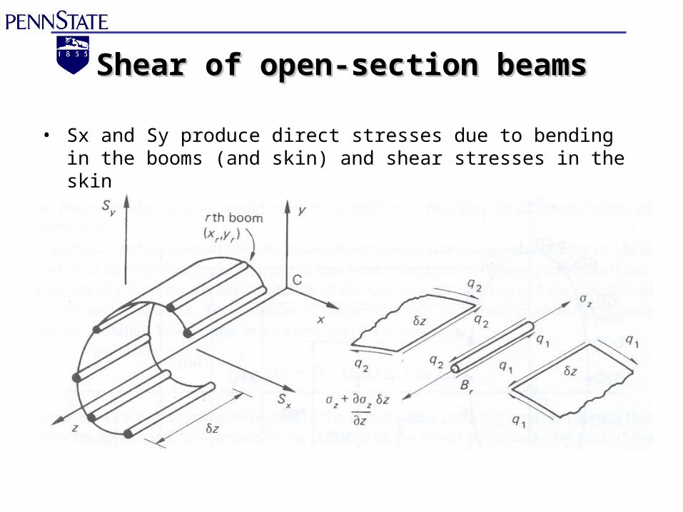
• Sx and Sy produce direct stresses due to bending in the booms (and skin) and shear stresses in the skin
Shear of open-section beamsShear of open-section beams
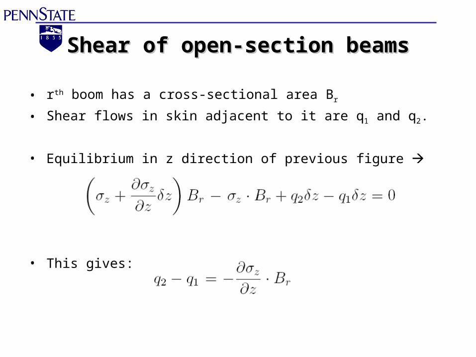
• rth boom has a cross-sectional area Br
• Shear flows in skin adjacent to it are q1 and q2.
• Equilibrium in z direction of previous figure
• This gives:
Shear of open-section beamsShear of open-section beams
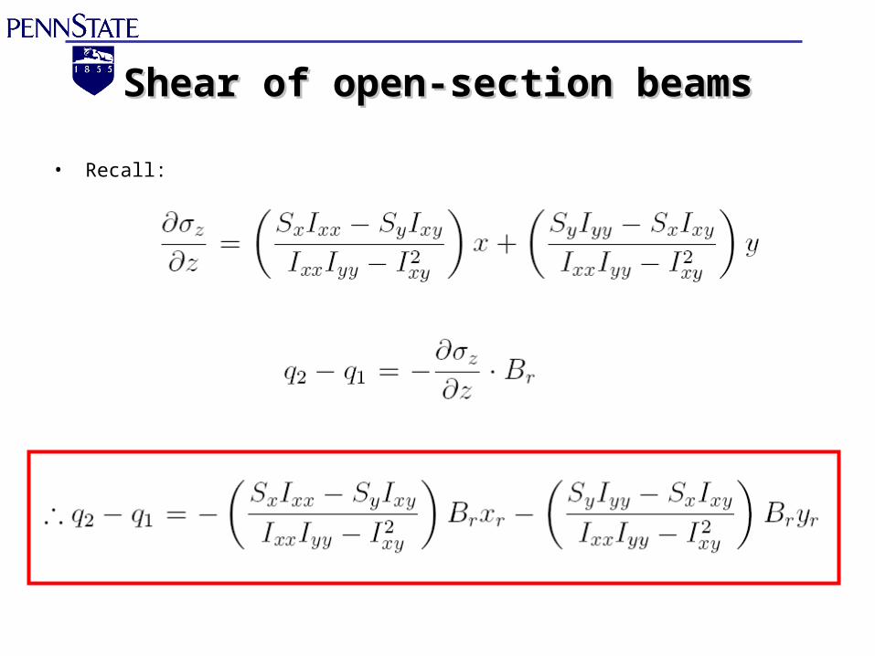
• Recall:
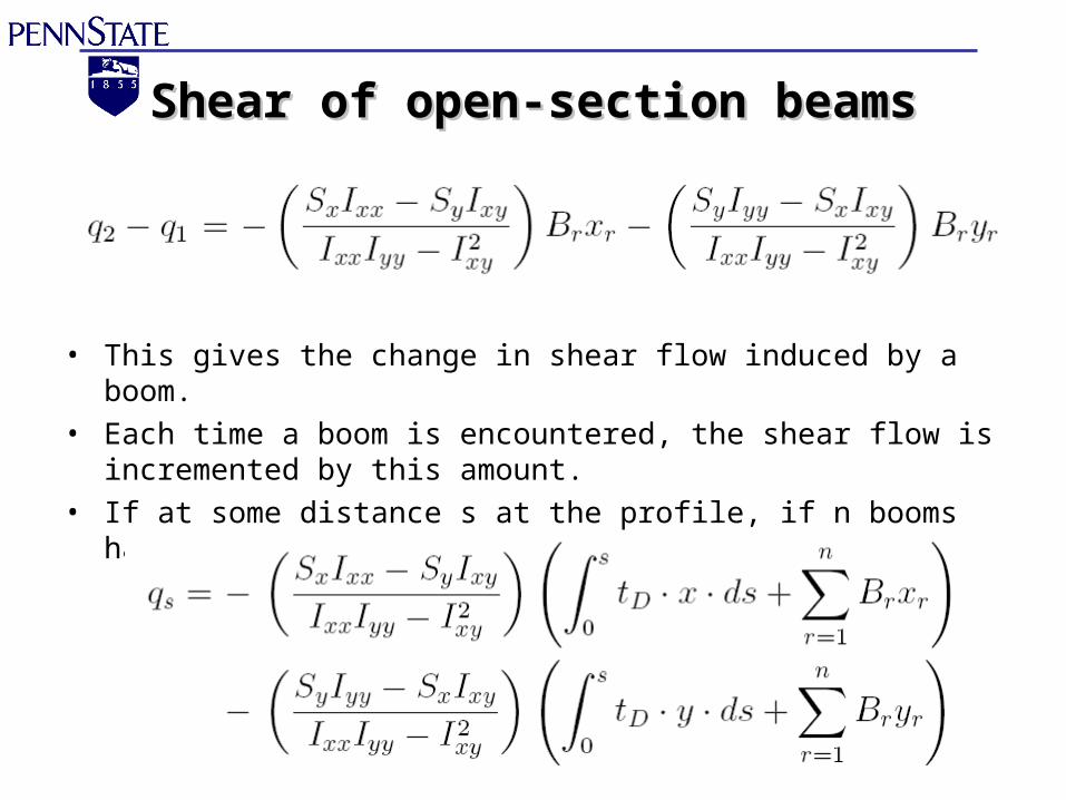
Shear of open-section beamsShear of open-section beams
• This gives the change in shear flow induced by a boom.• Each time a boom is encountered, the shear flow is incremented by
this amount. • If at some distance s at the profile, if n booms have been passed:

Open C/S Sample ProblemOpen C/S Sample Problem
• Calculate the shear flow distribution in channel due to a 4.8 kN vertical shear load acting through the shear center.
• Booms carry all the direct stresses (Br = 300 mm2)
n
rrr
xx
ys yB
I
Sq
1
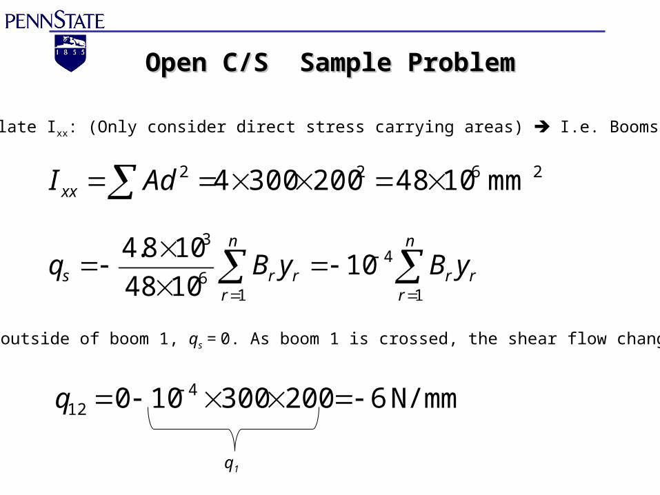
Open C/S Sample ProblemOpen C/S Sample Problem
2622 mm 10482003004 AdI xx
Calculate Ixx: (Only consider direct stress carrying areas) I.e. Booms
n
rrr
n
rrrs yByBq
11
46
3
101048
108.4
At the outside of boom 1, qs = 0. As boom 1 is crossed, the shear flow changes to:
N/mm 6200300100 412 q
q1

Open C/S Sample ProblemOpen C/S Sample Problem
There will be no further changes in shear flow until the next boom (2) is crossed.
At the outside of boom 4, the shear flow is zero (qs = 0) as expected
N/mm 12200300106 423 q
q2
N/mm 62003001012 434 q
q3
N/mm 0200300106 4
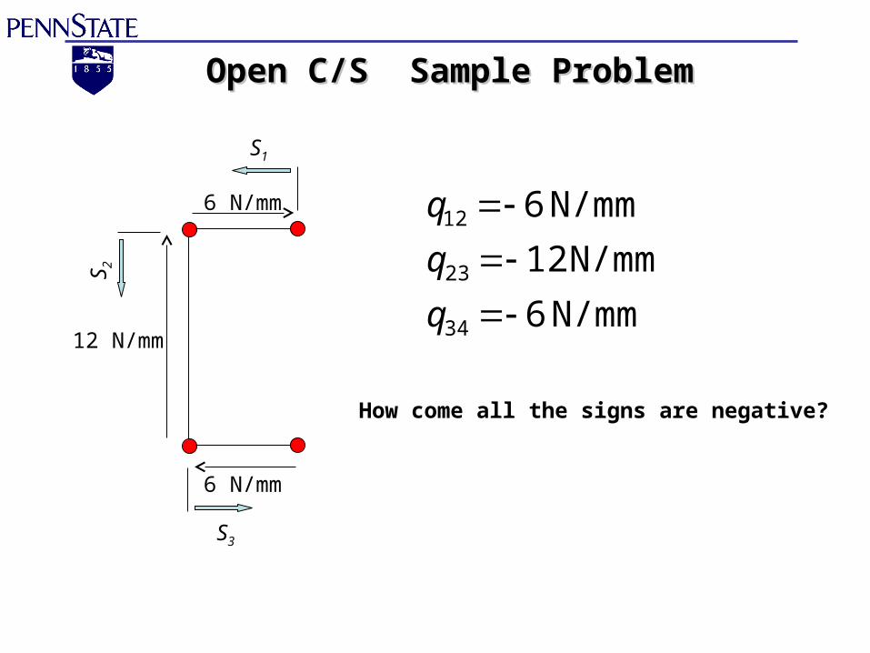
Open C/S Sample ProblemOpen C/S Sample Problem
6 N/mm
12 N/mm
6 N/mm
N/mm 6
N/mm 12
N/mm 6
34
23
12
q
q
q
How come all the signs are negative?
S1
S2
S3

Closed C/S Sample ProblemClosed C/S Sample Problem
• For the single cell beam, the booms carry the direct stresses and the walls carry only the shear stress. A vertical shear load of 10 kN acts through the vertical plane between booms 3 and 6. Calculate the shear flow distribution

Closed C/S Sample ProblemClosed C/S Sample ProblemCentroid on Horizontal Axis of Symmetry. Ixy = 0Also Sx = 0, tD = 0
n
rsrr
xx
ys qyB
I
Sq
10,
24
23
22
21 50100100302 BBBBI xx
Ixx can be calculated from the direct stress carrying area of the booms
Substituting B1,…B4 gives Ixx = 13.86 x 106 mm4
n
rsrr
n
rsrrs qyBqyBq
10,
4
10,6
3
1022.71086.13
1010

Closed C/S Sample ProblemClosed C/S Sample ProblemIntroduce a cut in the wall 23 and calculate the basic shear flow around the walls
N/mm 5.32501001022.79.28q
N/mm 9.281004001022.7
0
4b,45
434,
23,
b
b
q
qB3
y3
Since the tD = 0
y4B4
symmetry)(by 0
symmetry)(by N/mm 9.28
23,67,
34,56,
bb
bb
N/mm 4.22302001022.71.18
N/mm 1.181002501022.74
18,
421,
b
b
q
qy2B2
B1 y1
symmetry)(by N/mm 1.1821,87, bb qq

Closed C/S Sample ProblemClosed C/S Sample Problem
• Taking moments about the intersection of the line of action of shear load and horizontal axis:
0,20 sb Aqdspq is broken up into segments where each qb is constant
Draw out the shear flow distribution to determine the sign of the moment generatedby the shear flow on each segment
Solve for qs,0
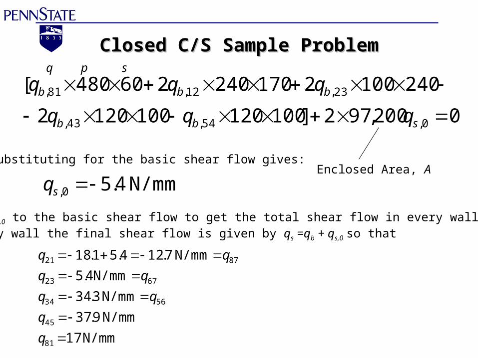
Closed C/S Sample ProblemClosed C/S Sample Problem
0200,972]1001201001202
2401002170240260480[
0,54,43,
23,12,81,
sbb
bbb
qqq
qqqq p s
Substituting for the basic shear flow gives:
N/mm 4.50, sq
Add qs,0 to the basic shear flow to get the total shear flow in every wall.In any wall the final shear flow is given by qs =qb + qs,0 so that
N/mm 17
N/mm 9.37
N/mm 3.34
N/mm4.5
N/mm 7.124.51.18
81
45
5634
6723
8721
q
q
Enclosed Area, A