Advantages Servogear EcoflowPropulsor V2 -...
8
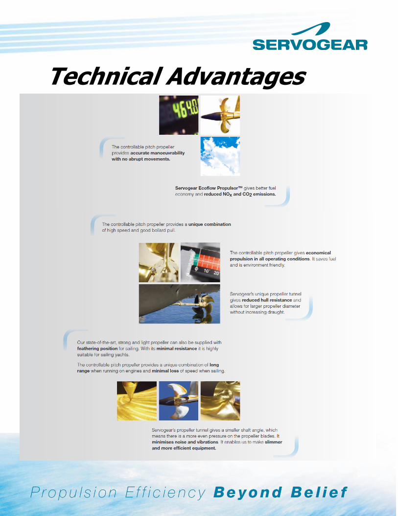
Technical Advantages
Transcript of Advantages Servogear EcoflowPropulsor V2 -...
Technical Advantages

Servogear AS, N-5420 Rubbestadneset, Norway Phone: + 47 53 42 39 50 | E-mail: [email protected] | www.servogear.no
Servogear Reduction gearbox/Servo system: • Gear housing in casted iron which gives low noise excitation. • Very compact design, with a rounded bottom to obtain a limited shaft angle. • Possibilities for PTO drive: 200kW @ 2100RPM • Three different configurations:
H-gear (in line)
U-gear (engine aft)
PTI (twin in single out)
• High quality gear wheels according to DIN 3961-3963-L5 • It is compatible with most types of control systems • Custom built gearbox mountings on request. • Possibilities for analogue sensors on request • Integrated servo system for pitch alteration:

Servogear AS, N-5420 Rubbestadneset, Norway Phone: + 47 53 42 39 50 | E-mail: [email protected] | www.servogear.no
Servogear CP propellers: The propeller hub is of well-known and proven design. Pitch actuation is done through a mechanical connection from the blades to a hydraulic actuation system inside the gear-box (push-pull rod through the propeller shaft). This is a very simple and robust system which requires very limited maintenance work. Both the propeller hub and the blades are made of NiAlBz material and have possibilities for feathering position. Servogear Propeller tunnel design: 1. Optimum flow into the propeller A Servogear propeller tunnel is designed according to the propeller momentum theory and will therefore secure optimum water flow through the propeller. The shape of the tunnel from the propeller to the stern is designed in accordance with the contraction of the water flow calculated from the propeller momentum theory. The tunnel is tailor made for each project. 2. Optimum propeller diameter Normally, the propeller diameter is limited by the tip clearance and the draft. A propeller tunnel will give space for an optimum propeller diameter (largest possible with acceptable shaft inclination). This is very favourable considering high propulsion efficiency and low noise and vibration (reduced surface pressure and tip speed on the propeller). 3. Reduced shaft angle A propeller tunnel will also minimize the shaft angle and reduce the thrust variation on the propeller. This will again reduce the peak load on the propeller and thus increase the lifetime of the equipment significantly. The reduced shaft angle will also reduce the drag caused by the shaft and brackets etc. 4. Reduced ship resistance Based on experience from sea trials and model tests, a propeller tunnel normally reduces the ship resistance. The reduced resistance is caused by less transom area, which again reduces the loss in stern wave energy.

Servogear AS, N-5420 Rubbestadneset, Norway Phone: + 47 53 42 39 50 | E-mail: [email protected] | www.servogear.no
Servogear Shaft Brackets: The brackets are of heavy-duty single leg design. They are cast in the same stainless steel material as the rudders, and are mounted into the hull structure by chock fast. Due to its design and location, the brackets stabilise the water flow into the propellers (no turbulence and better steering performance to the hull). Designed with progressive strength (as the rudders). Progressive strength means that the section modulus of the bracket leg is decreasing from the hull intersection to the bracket barrel. If a severe grounding occurs, the bracket will be deformed as a “J”, avoiding serious damages to the hull like cracks and leakage. The detail is very important for the safety. Normally, the brackets can be easily straightened (no replacement necessary). Bracket installation
Bracket damages on MS Baronen after severe grounding at speed 30 knots. Note the “J” shaped deformation.

Servogear AS, N-5420 Rubbestadneset, Norway Phone: + 47 53 42 39 50 | E-mail: [email protected] | www.servogear.no
Propulsive efficiency
Through continuous theoretical and practical research, Servogear has developed an increasingly efficient propulsion system which today is successfully running in a great number of vessels all over the world. We achieve ground-breaking results through our all-inclusive approach. Our propeller tunnel allows for larger propeller diameter with no increase of shaft angle and draught. Propeller Rpm is reduced, as well as the surface pressure on the propeller blades, and the water flow entering the propeller is optimised. Together with some other details, this provides the propeller with the best possible working conditions resulting in a smooth and optimum propeller thrust. A more even loaded propeller gives a slimmer and lighter design, which means less weight and drag as well as higher efficiency. Calculations and design of our propeller tunnels is based on full utilisation of the flow below the hull, ensuring optimum interaction between hull and propulsion. Efficient propulsion means lower fuel consumption, more economic operation and less pollution. Tank tests and full-scale verification tests have proven that the Servogear Ecoflow PropulsorTM is more efficient than any other known propulsion.

Servogear AS, N-5420 Rubbestadneset, Norway Phone: + 47 53 42 39 50 | E-mail: [email protected] | www.servogear.no
A brief comparison of CP-propeller and FP-propeller:
• Acceleration of a vessel with CPPs is considerable better than for FPPs, because for a CPP the pitch can be increased as the vessel speed and load increase. For a FPP the pitch will be to high during acceleration, hence cavitations is severe and the engine is easily overloaded.
• Most vessels of today are equipped with automatic overload control system (integrated part
of the remote control system). Should the engine be overloaded the pitch will be reduced automatically down to the programmed load curve of the engine.
• If there is high variations in displacements on the vessel (from running fully loaded in strong
ahead wind, to run empty in tail winds) a CPP gives much higher total efficiency than any other propulsion system. In general, when running at different off-design conditions, the efficiency of a CPP is far better than for a FPP.
• Between docking the fouling of the hull increases the resistance. By altering the pitch, the
engine can still run at an optimum load. • When running in harbour areas the speed of the vessel can be reduced all the way down to
zero speed. Manoeuvring is very smooth and precise (no sudden movements).
• With a CPP the engines can be running optimum in different load/weather conditions, see examples below.

Servogear AS, N-5420 Rubbestadneset, Norway Phone: + 47 53 42 39 50 | E-mail: [email protected] | www.servogear.no
A. - Engine is running at its design condition
- Propeller efficiency is the same for FPP and CPP - FPP can only reach this condition for one displacement.
B. - The boat has a light displacement and resistance is reduced.
- The pitch on the CPP is increased until engines are run on condition A. - The FPP cannot take fully advantage of the engine. - The maximum engine output and maximum speed is reduced for FPP compared to CPP
C. - The vessel has a large displacement and the resistance has increased.
- This is the most severe condition due to possible overload of the engine. - The pitch of the CPP is reduced until engine run on condition A. - The FPP curve indicates that maximum rev can not be achieved. - The FPP can not take fully advantage of the engine. - In practice, the engine should not be run in condition C, due to thermal overloading and
hence reduction of lifetime. The engine revs and maximum output should be further reduced for a FPP vessel.
- The maximum engine output should be further reduced for a FPP vessel compared to a CPP.
1. Higher efficiency, the CP propeller offers better long distance range at cruising speed.
Typical data @ 35 Knots CPP Tunnel FPP No tunnel Propeller diameter 1750 1125 Open water efficiency 77% 67% Propeller tip speed 30 m/s 56 m/s Surface pressure 0,50 bar 0,73 bar Shaft inclination 4 degrees 6,5 degrees Reduced wet stern area approximately 40%

Servogear AS, N-5420 Rubbestadneset, Norway Phone: + 47 53 42 39 50 | E-mail: [email protected] | www.servogear.no
The Servogear Effect rudders: Designed effect rudders are shaped like a vane, where each section follows the different angles of the water flow leaving the propeller, hence minimum drag on the rudder. The cross-sections of the rudder blade are designed as an aeroplane wing giving a lift in the water flow, which again produces a forward thrust. Arrangement of the effect rudder / propeller cone is designed to gain some of the loss of rotation energy in the slip stream (increase the relative rotation efficiency). The inclined water flow from the propeller generates a pressure and a suction side on the rudder blade. Due to the seal between the rudder and the propeller cone, the pressure balancing will be forced to work in opposite direction of the rotating water flow from the propeller and therefore reduce the loss of rotational energy. Our rudders are made of high tensile stainless steel castings to reduce the blade thickness to a minimum. Finally, Servogear effect rudders are designed with progressive strength (see explanation under the shaft bracket paragraph)
Principle drawing – advantages Servogear effect rudder
Full sail feathering position
Our design philosophy. Servogear`s philosophy is to work closely together with the ship designers during development of hull lines to obtain an optimum interaction between hull and propulsion system, resulting in the best possible performance. We hope this information will illustrate some of the benefits with Servogear Ecoflow Propulsor.