Advancing Fiber Optic Connectivity - BICSI · Presentation Overview • Tooling Requirements and...
33
Advancing Fiber Optic Connectivity Fusion Spice-On Connectors by Brad Everette, America Ilsintech, Dallas, TX and Seung-Min Lee, Ilsintech, Daejeon, South Korea
Transcript of Advancing Fiber Optic Connectivity - BICSI · Presentation Overview • Tooling Requirements and...
Advancing Fiber Optic ConnectivityFusion Spice-On Connectors
by
Brad Everette, America Ilsintech, Dallas, TXand
Seung-Min Lee, Ilsintech, Daejeon, South Korea

Presentation Overview• Advancements in Fiber Optic Connectivity
– Shift toward Fusion Splice-On Connectivity (FSOC)– Specification in Installation
• Distinguishable Benefits of FSOC– Performance– Quality– Efficiency– Case Study
• Market Factors Affecting Migration– Product Life Cycle– Associated Technology

Presentation Overview• Tooling Requirements and Associated Factors
– Alignment Technology– Splicer Designs and Product Advancements
• Break• Panel Discussion

Shift Toward Fusion Splice on Connectivity

Shift Toward Fusion Splice-On Connectivity
• FSOC is a fully standards compliant Connector Solution– Fully Interoperable…not proprietary
• TIA, IEEE, IEC and Telcordia Standards compliant• Division 27 Specifications Available• With FTTH Beginnings, gaining widespread adoption in Enterprise
and Data Center Markets

Shift Toward Fusion Splice-On Connectivity• FSOC is a fully standards compliant Connector Solution
– Designed using the best of previous generation connectivity solutions
• Factory Polished Connectors from Legacy Mechanical Designs• Performance and Quality from Pigtail Splicing in the field• Accommodates weaknesses in previous generation designs and
implementation

• FSOC is a fully standards compliant Connector Solution– SC/LC/ST/FC…and MPO Connector Availability
• Can be spliced to 250&900um buffers and up to 3mm jackets• MPO can be spliced directly to ribbon fiber• MPO can also be spliced directly to loose tube fibers
– Ribbonization of loose fibers required– …or NOT?! More on that later.
Shift Toward Fusion Splice-On Connectivity

Specification and Installation
Specification and Installation• FSOC can be offered as a technical equivalent in design
specifications• Fully Interoperable with legacy passive panels and active
equipment– Specific termination procedures are required (like any other)– Specific termination equipment is required (like any other)– Visit the relevant booths here at BICSI

Specification and Installation
• Quantifiable Benefits are realized by both the User and the Installer– Performance– Quality/Durability– Efficiency/Economics

Distinguishable Benefits of FSOC
Distinguishable Benefits of FSOC
• Performance– Factory Polish similar to Mechanical and Pigtail Solutions– Fusion Splice provides better fiber alignment
• Improved performance vs. Mechanical Connectors • Similar performance to Pigtail Splicing• Varying levels of improvement based on alignment method
Distinguishable Benefits of FSOC
• Quality/Durability– No Index Matching Gel– Direct splice provides better fiber retention– Shrink sleeve with splice support provides better fiber
retention
Distinguishable Benefits of FSOC
• Efficiency/Economics– Better quality and durability results in less maintenance
and less downtime– Splicing directly at the connector (under the boot) results
in removal of splice trays. This results in more efficient installation, more economical installation and less congestion in racks and cabinets.

Case StudyData Collected and summarized by Ilsintech using original report from
Japan NTT

Causes of Faults and Failures 1. Fiber Gap & Incorrectly cleaved fiber ends
We collected actual defective field assembly connectors from an area of Japan and checked their optical characteristics and dismantled them to identify the cause of the fault. 12% of the faults were caused by increased optical loss due to incorrect cleaving of the optical fiber. An incorrectly cleaved fiber end is shown in above.

Causes of Faults and Failures 2. Fiber connection with refractive index matching material
(a)shows the normal connection state with a narrow gap between flat fiber ends, (b) shows an abnormal connection state with a wide gap between flat fiber ends (c) shows an abnormal state with an incorrectly cleaved (uneven) fiber end.
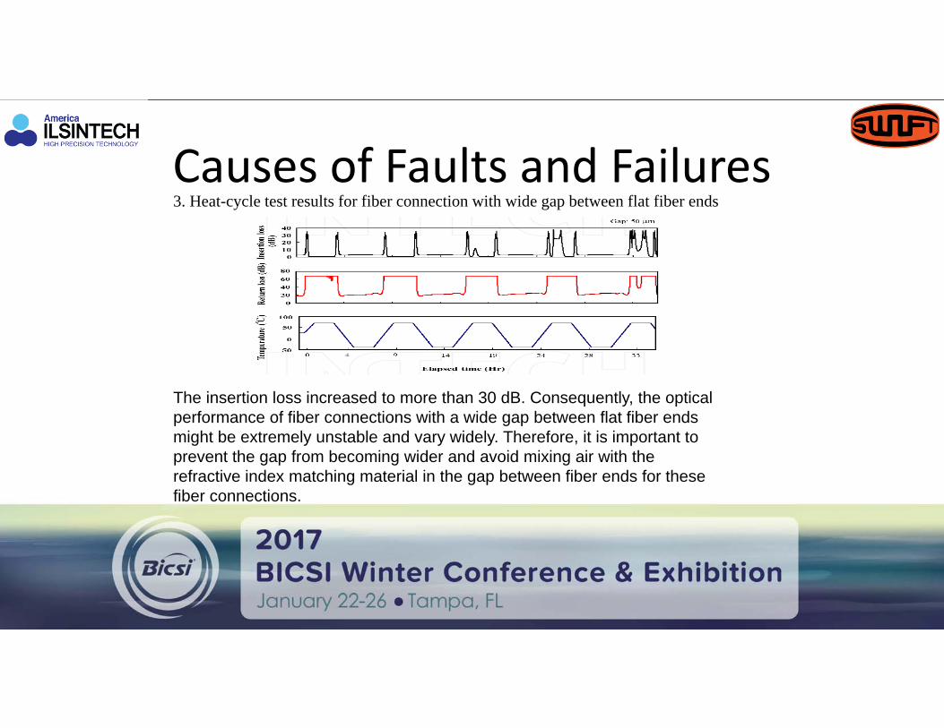
Causes of Faults and Failures 3. Heat-cycle test results for fiber connection with wide gap between flat fiber ends
The insertion loss increased to more than 30 dB. Consequently, the optical performance of fiber connections with a wide gap between flat fiber ends might be extremely unstable and vary widely. Therefore, it is important to prevent the gap from becoming wider and avoid mixing air with the refractive index matching material in the gap between fiber ends for these fiber connections.

Causes of Faults and Failures 4. Scatter diagrams of results from heat cycle test for fiber connection with an incorrectly cleaved (uneven)
The initial insertion loss was low at about 1 dB and the initial return loss was high at more than 40 dB. The insertion loss increased greatly and then the return loss decreased as the temperature changed. At worst, the insertion loss changed to 43 dB and the return loss changed to 28 dB.
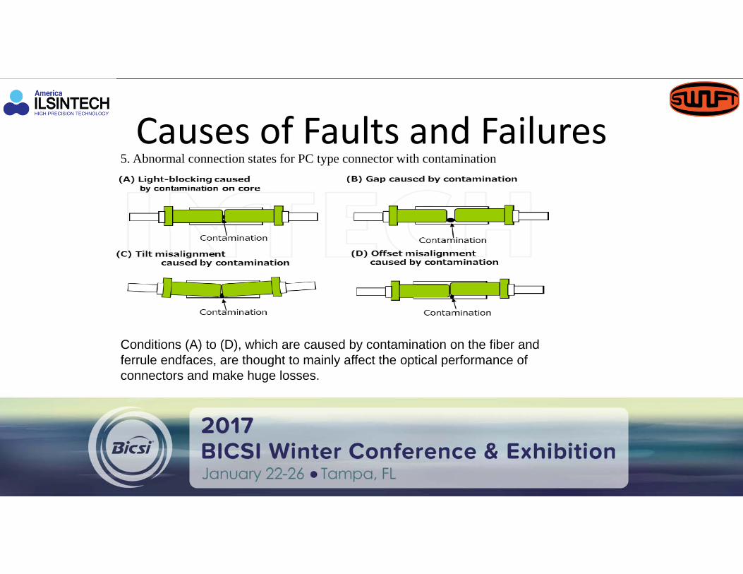
Causes of Faults and Failures 5. Abnormal connection states for PC type connector with contamination
Conditions (A) to (D), which are caused by contamination on the fiber and ferrule endfaces, are thought to mainly affect the optical performance of connectors and make huge losses.

Causes of Faults and Failures 6. Calculated insertion loss(A)cover ratio of contamination to fiber core(B) caused by air-filled gap(C) caused by tilt(D)caused by offset

Causes of Faults and Failures 7. Causes of field assembly connector faults.

Causes of Faults and Failures 8. Examples of scratched optical fibers.

Causes of Faults and Failures • FSOC Termination Method with Quality Connectors and
Quality Tools corrects these issues resulting in higher adoption in the market.– Quality Connectors
• Field Strip and Cleave provide cleanest solution.
– Quality Splicers– Quality Cleavers

Causes of Faults and Failures

Market Factors Affecting Migration

Life Cycle of Products• Product Life Cycle Model
– Introduction…New Products still with a few bugs
– Growth…Bugs worked out, costs go down, followed by rapid adoption
– Maturity…Widely accepted products with few new features/benefits. Shortcomings are known and people are looking for a new alternative.
– Decline…obsolete technology, but still used by a few in legacy networks.

Life Cycle of Products
Mechanical Connectors are late in the Maturity Stage• Few New Products• Few New Features/Benefits• Flaws are known and
accepted• Market looking for a new
solution

Life Cycle of Products
FSOC is in the Growth Stage• Fully developed technology• Rapid Adoption• Solves previous generation
problems• Support from related
technology

Associated Technology
• Thermal Strippers• Cleaning Products• Precision Cleavers• Faster Splice Times• Fusion Splicer Sizes• Fusion Splicer Costs

Associated Technology
• Splicer Alignment Methods– V-Groove– Active Clad– IPAAS Core– Ribbon Fibers
Need Images!

Associated Technology Or…All In One Splicer Designs
• Thermal Stripper• Cleaner• Cleaver• Splicer• Sleeve Heater

Associated Technology
• MPO Connector Termination– Splice to Ribbon Fiber– Splice to Loose Tube Fiber – Loose Tube MultiFiber Holder
Need Images!