ADVANCES IN CORE TECHNOLOGY - … · ADVANCES IN CORE TECHNOLOGY Julian Lucek New Network Technical...
47
ADVANCES IN CORE TECHNOLOGY Julian Lucek New Network Technical Forum, September 2012
Transcript of ADVANCES IN CORE TECHNOLOGY - … · ADVANCES IN CORE TECHNOLOGY Julian Lucek New Network Technical...
ADVANCES IN CORE TECHNOLOGY
Julian Lucek
New Network Technical Forum, September 2012
2 Copyright © 2012 Juniper Networks, Inc. www.juniper.net
LEGAL STATEMENT
This statement of product direction sets forth Juniper Networks’
current intention and is subject to change at any time without
notice. No purchases are contingent upon Juniper Networks
delivering any feature or functionality depicted in this
presentation.
3 Copyright © 2012 Juniper Networks, Inc. www.juniper.net
AGENDA
Core trends - and associated requirements
PTX - design philosophy and architecture
Optical Integration into routers
Advances in multichassis technology

4 Copyright © 2012 Juniper Networks, Inc. www.juniper.net
Migration to Packet-based Services
Packet Switching (MPLS)
DWDM
Fibre
Vo
IP
Internet
Pri
va
te
Cir
cu
its, A
TM
,
Fra
me
Rela
y
IP V
PN
s
IPT
V/V
oD
TV
Infr
astr
uctu
re
TDM Circuit
Switching
(SONET/SDH or OTN)
PO
TS
(6
4k
cir
cu
its)
SERVICES
INFRA
Mo
bile
vo
ice
Eth
ern
et,
AT
M,
FR
PW
s
TV
Infr
astr
uctu
re
5 Copyright © 2012 Juniper Networks, Inc. www.juniper.net
0
0.1
0.2
0.3
0.4
0.5
0.6
0.7
0.8
0.9
1
time
Packet-switched traffic
Circuit-switched traffic
Re
lative
pro
po
rtio
n
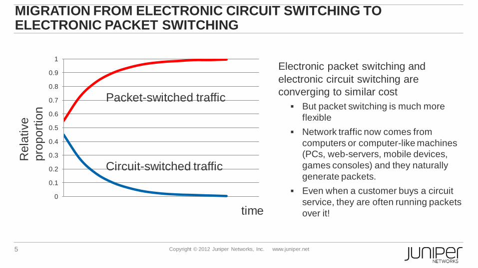
MIGRATION FROM ELECTRONIC CIRCUIT SWITCHING TO ELECTRONIC PACKET SWITCHING
Electronic packet switching and
electronic circuit switching are
converging to similar cost
But packet switching is much more
flexible
Network traffic now comes from
computers or computer-like machines
(PCs, web-servers, mobile devices,
games consoles) and they naturally
generate packets.
Even when a customer buys a circuit
service, they are often running packets
over it!

6 Copyright © 2012 Juniper Networks, Inc. www.juniper.net
REQUIREMENTS FOR THE MPLS CORE
Needed:
IPv4, IPv6, MPLS forwarding
Highest possible capacity
High-speed Ethernet ports only (10GE, 40GE, 100GE)
IP Multicast
MPLS Multicast (P2MP LSPs)
Not needed:
Full internet routing table in FIB
Edge services (VPLS, L3VPN, Subs Mgmt..)

7 Copyright © 2012 Juniper Networks, Inc. www.juniper.net
SYSTEM CAPACITY AS FUNCTION OF TIME
time
System
throughput
(log scale) General purpose
core/edge router
Streamlined core
router

8 Copyright © 2012 Juniper Networks, Inc. www.juniper.net
PTX5000: SHIPPING SINCE MARCH 2012
PTX 5000
17.6’’ (19’’ rack) x 33’’x62, (WxDxH)
Max power consumption: 11kW
Typical power consumption: 6.2kW
8 line card slots, 2 PICs per slot
10GE: 384
40GE: 32
100GE: 32
Port counts (line-rate, full-duplex)
•Highest capacity in the entire industry
•Junos operating system
•Very low latency: ~7 microseconds for 512 byte packet on 10GE link
•Record low Energy Consumption Ratio (ECR) of 1.54 Gbps/W
9 Copyright © 2012 Juniper Networks, Inc. www.juniper.net
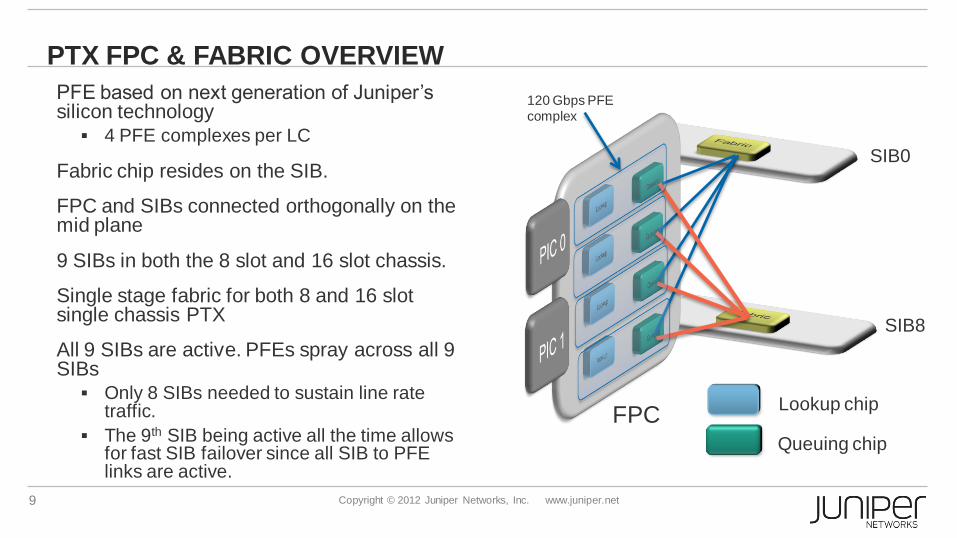
PTX FPC & FABRIC OVERVIEW
PFE based on next generation of Juniper’s silicon technology 4 PFE complexes per LC
Fabric chip resides on the SIB.
FPC and SIBs connected orthogonally on the mid plane
9 SIBs in both the 8 slot and 16 slot chassis.
Single stage fabric for both 8 and 16 slot single chassis PTX
All 9 SIBs are active. PFEs spray across all 9 SIBs Only 8 SIBs needed to sustain line rate
traffic.
The 9th SIB being active all the time allows for fast SIB failover since all SIB to PFE links are active.
SIB0
SIB8
Lookup chip
Queuing chip
120 Gbps PFE
complex
FPC
10 Copyright © 2012 Juniper Networks, Inc. www.juniper.net
PTX KEY FUNCTIONALITY
IGP protocols, including TE extensions: ISIS, OSPF
MPLS protocols: o RSVP TE, LDP
o LSP Hierarchy: LDP over RSVP, RSVP over RSVP, Labelled BGP (RFC 3107)
LSP protection schemes o Primary/Secondary RSVP LSP
o RSVP Fast-Reroute (1:1 protection, link protection, node protection). FRR for 50000 LSPs takes less than 20ms.
o IP Fast Reroute (Loop-Free Alternates) for OSPF, ISIS (+ LDP)
11 Copyright © 2012 Juniper Networks, Inc. www.juniper.net
PTX KEY FUNCTIONALITY
MPLS Multicast: o RSVP P2MP, LDP P2MP
IP Multicast: PIM
BGP (but not full internet table in FIB)
Route Reflector support for all BGP address families
Seamless MPLS Border Node; Interprovider Option B and C

12 Copyright © 2012 Juniper Networks, Inc. www.juniper.net
PTX KEY FUNCTIONALITY
BFD, including BFD over MPLS LSPs
LSP ping and traceroute
Ethernet OAM (802.1ag and 802.3ah)
PE for Point-to-point pseudowires: LDP signalling (L2circuit), BGP signalling (L2VPN) VCCV and VCCV-BFD
Firewall Filters and Policers Including Two-Rate Tricolour Marking, Single-Rate Tricolour marking
ECMP over 64 paths
LAG with 64 child links
Synchronous Ethernet
13 Copyright © 2012 Juniper Networks, Inc. www.juniper.net
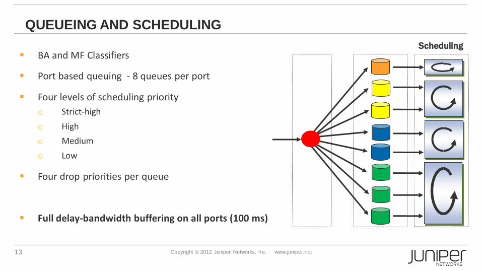
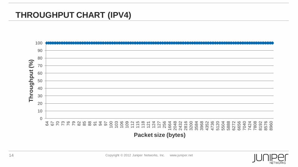
QUEUEING AND SCHEDULING
BA and MF Classifiers
Port based queuing - 8 queues per port
Four levels of scheduling priority
o Strict-high
o High
o Medium
o Low
Four drop priorities per queue
Full delay-bandwidth buffering on all ports (100 ms)
Scheduling
14 Copyright © 2012 Juniper Networks, Inc. www.juniper.net
THROUGHPUT CHART (IPV4)
0
10
20
30
40
50
60
70
80
90
100 6
4
67
70
73
76
79
82
85
88
91
94
97
10
0
10
3
10
6
10
9
11
2
11
5
11
8
12
1
12
4
12
7
25
6
16
64
20
48
24
32
28
16
32
00
35
84
39
68
43
52
47
36
51
20
55
04
58
88
62
72
66
56
70
40
74
24
78
08
81
92
85
76
89
60
Th
rou
gh
pu
t (%
)
Packet size (bytes)

15 Copyright © 2012 Juniper Networks, Inc. www.juniper.net
THROUGHPUT CHART (IPV6)
0
10
20
30
40
50
60
70
80
90
100
78
81
84
87
90
93
96
99
10
2
10
5
10
8
11
1
11
4
11
7
12
0
12
3
12
6
19
6
15
00
19
20
23
04
26
88
30
72
34
56
38
40
42
24
46
08
49
92
53
76
57
60
61
44
65
28
69
12
72
96
76
80
80
64
84
48
88
32
Th
rou
gh
pu
t (%
)
Packet size (bytes)

16 Copyright © 2012 Juniper Networks, Inc. www.juniper.net
THROUGHPUT CHART (MPLS)
0
10
20
30
40
50
60
70
80
90
100 6
4
67
70
73
76
79
82
85
88
91
94
97
10
0
10
3
10
6
10
9
11
2
11
5
11
8
12
1
12
4
12
7
25
6
16
64
20
48
24
32
28
16
32
00
35
84
39
68
43
52
47
36
51
20
55
04
58
88
62
72
66
56
70
40
74
24
78
08
81
92
85
76
89
60
Th
rou
gh
pu
t (%
)
Packet size (bytes)
17 Copyright © 2012 Juniper Networks, Inc. www.juniper.net
PTX CUSTOMER ANNOUNCEMENTS
London Internet Exchange (LINX) https://www.linx.net/publicity/2011releases/pr2011-01.html
http://www.nanog.org/meetings/nanog54/presentations/Wednesday/Cobb.pdf
http://www.youtube.com/watch?v=F8WrVakhPwI&featu
Verizon http://newscenter.verizon.com/press-releases/verizon/2012/verizon-to-
deploy-the.html
“Verizon plans to deploy the Juniper Networks® PTX Series in major markets in the U.S. and Europe by the end of this year, giving the company the densest multiprotocol label switching platform available in the industry, with an initial capacity of eight terabits per second”
18 Copyright © 2012 Juniper Networks, Inc. www.juniper.net
TREND: CONSOLIDATION OF PACKET NETWORKS
Some operators have ended up having multiple packet networks for
different purposes, for example:
Separate Public IP and Private IP networks
Or separate Business and Residential networks
Or separate L3 networks and L2 networks
However, this is inefficient for both CAPEX and OPEX reasons, and
reduces one of the key benefits of packet networks: efficient bandwidth
utilisation through packet aggregation, statistical multiplexing.
Hence there is now a strong trend to consolidate these separate
networks.
19 Copyright © 2012 Juniper Networks, Inc. www.juniper.net
TREND: CONSOLIDATION OF THE PACKET NETWORKS (CONT’D)
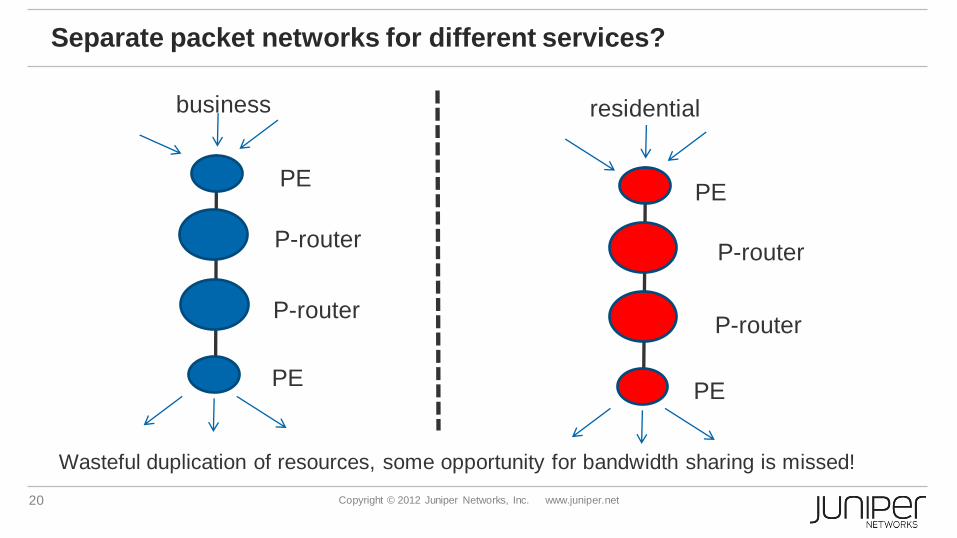
Also the traffic patterns are complementary:
Business Services (e.g. L3VPN, Layer 2 services) peak during
the day
Residential peaks during the evening
Packet schedulers/queues give segregation between
different services, while still allowing them to use each
other’s spare bandwidth, on a millisecond by millisecond
basis
20 Copyright © 2012 Juniper Networks, Inc. www.juniper.net
Separate packet networks for different services?
Wasteful duplication of resources, some opportunity for bandwidth sharing is missed!
P-router
P-router
P-router
P-router
PE
PE
PE
PE
business residential
21 Copyright © 2012 Juniper Networks, Inc. www.juniper.net
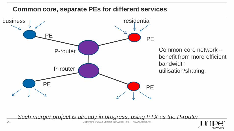
Common core, separate PEs for different services
Common core network –
benefit from more efficient
bandwidth
utilisation/sharing.
P-router
P-router
PE
PE
PE
PE
business residential
Such merger project is already in progress, using PTX as the P-router

22 Copyright © 2012 Juniper Networks, Inc. www.juniper.net
Common core, common PEs (MultiService Edge)
P-router
P-router
PE
PE
PE
PE
All services All services
23 Copyright © 2012 Juniper Networks, Inc. www.juniper.net
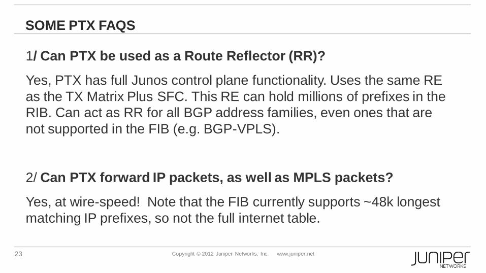
SOME PTX FAQS
1/ Can PTX be used as a Route Reflector (RR)?
Yes, PTX has full Junos control plane functionality. Uses the same RE
as the TX Matrix Plus SFC. This RE can hold millions of prefixes in the
RIB. Can act as RR for all BGP address families, even ones that are
not supported in the FIB (e.g. BGP-VPLS).
2/ Can PTX forward IP packets, as well as MPLS packets?
Yes, at wire-speed! Note that the FIB currently supports ~48k longest
matching IP prefixes, so not the full internet table.

OPTICAL INTEGRATION
25 Copyright © 2012 Juniper Networks, Inc. www.juniper.net
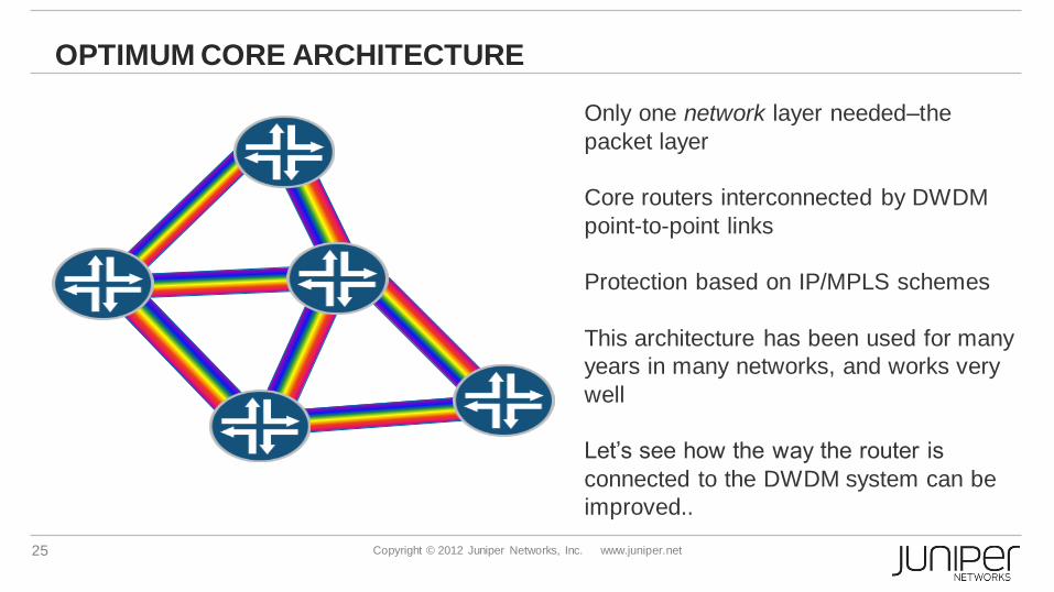
OPTIMUM CORE ARCHITECTURE
Only one network layer needed–the
packet layer
Core routers interconnected by DWDM
point-to-point links
Protection based on IP/MPLS schemes
This architecture has been used for many
years in many networks, and works very
well
Let’s see how the way the router is
connected to the DWDM system can be
improved..

26 Copyright © 2012 Juniper Networks, Inc. www.juniper.net
Grey interfaces versus Coloured interfaces
No transponder on DWDM system!
Coloured, tunable 100 GE interface on the router.
Long-haul coloured optics
Transponder
on DWDM
system
Transponder
on DWDM
system
CFP grey optics CFP grey optics
Router Router
Router Router
27 Copyright © 2012 Juniper Networks, Inc. www.juniper.net
INTEGRATION=SIMPLIFICATION: ANALOGIES FROM THE PAST
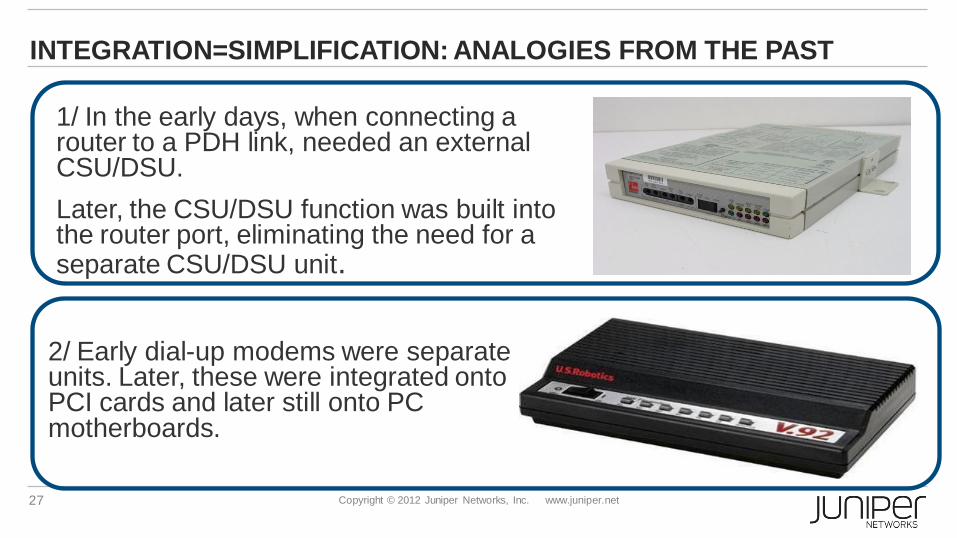
1/ In the early days, when connecting a router to a PDH link, needed an external CSU/DSU.
Later, the CSU/DSU function was built into the router port, eliminating the need for a separate CSU/DSU unit.
2/ Early dial-up modems were separate units. Later, these were integrated onto PCI cards and later still onto PC motherboards.
v
v
28 Copyright © 2012 Juniper Networks, Inc. www.juniper.net
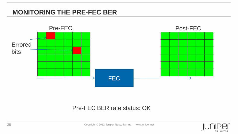
MONITORING THE PRE-FEC BER
FEC
Pre-FEC BER rate status: OK
Pre-FEC Post-FEC
Errored
bits

29 Copyright © 2012 Juniper Networks, Inc. www.juniper.net
MONITORING THE PRE-FEC BER (CONT’D)
FEC
Pre-FEC BER rate status: signal degrade.
=> Link down and FRR triggered before packets are lost.
Pre-FEC Post-FEC
Errored
bits

30 Copyright © 2012 Juniper Networks, Inc. www.juniper.net
COHERENT DETECTION
00
01 10
11
Above diagram is for one polarisation. Using the orthogonal polarisation in addition,
carry 4 bits per symbol in total (DP-QPSK)
•Very resilient to
chromatic dispersion (CD)
and polarisation mode
dispersion (PMD)!
•Removes need for in-line
CD and PMD
compensators
•Good spectral efficiency
(2 bps/Hz)
31 Copyright © 2012 Juniper Networks, Inc. www.juniper.net
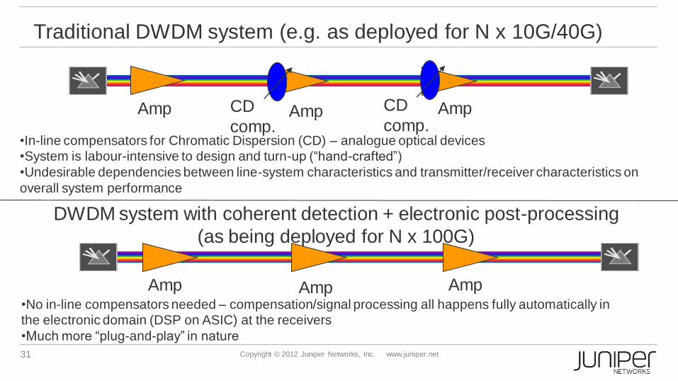
Traditional DWDM system (e.g. as deployed for N x 10G/40G)
•In-line compensators for Chromatic Dispersion (CD) – analogue optical devices
•System is labour-intensive to design and turn-up (“hand-crafted”)
•Undesirable dependencies between line-system characteristics and transmitter/receiver characteristics on
overall system performance
Amp Amp Amp
DWDM system with coherent detection + electronic post-processing
(as being deployed for N x 100G)
•No in-line compensators needed – compensation/signal processing all happens fully automatically in
the electronic domain (DSP on ASIC) at the receivers
•Much more “plug-and-play” in nature
Amp Amp Amp
CD
comp. CD
comp.
32 Copyright © 2012 Juniper Networks, Inc. www.juniper.net
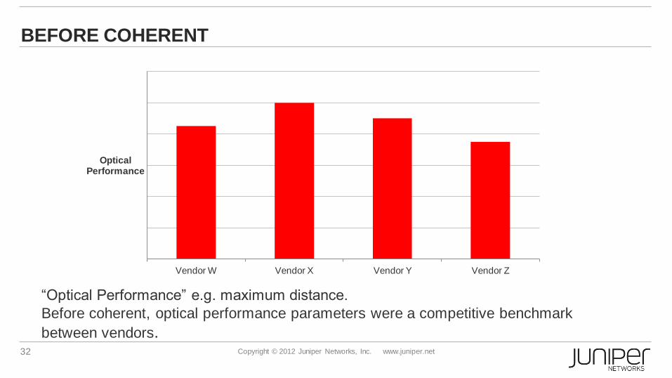
BEFORE COHERENT
“Optical Performance” e.g. maximum distance.
Before coherent, optical performance parameters were a competitive benchmark
between vendors.
Vendor W Vendor X Vendor Y Vendor Z
Optical Performance
33 Copyright © 2012 Juniper Networks, Inc. www.juniper.net
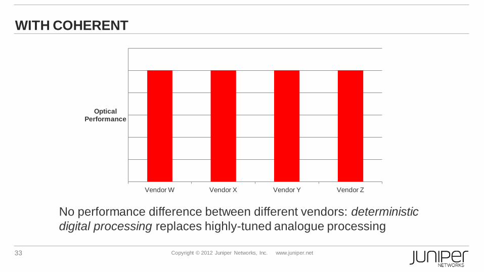
WITH COHERENT
Vendor W Vendor X Vendor Y Vendor Z
Optical Performance
No performance difference between different vendors: deterministic
digital processing replaces highly-tuned analogue processing

34 Copyright © 2012 Juniper Networks, Inc. www.juniper.net
OTS-1000 DWDM SYSTEM
Complements coloured 100G interfaces on router
Supports 96 wavelengths @ 100G
System reach of 2500km
Flexible bandwidth allocation for future modulation
formats
High performance optical amplification
Integrated hybrid EDFA + Raman for various fiber types
Extended C band support
Low noise figure & high flatness
No dispersion compensation module needed
35 Copyright © 2012 Juniper Networks, Inc. www.juniper.net
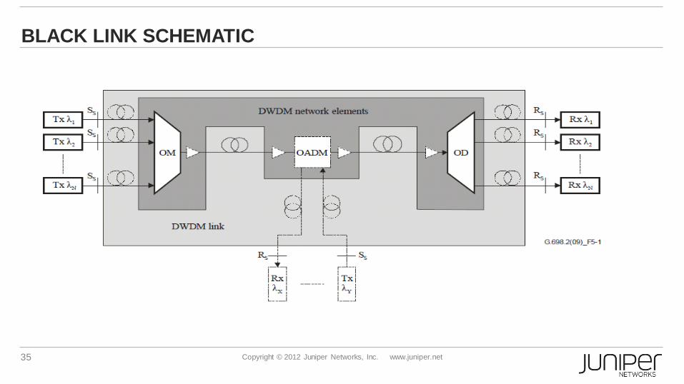
BLACK LINK SCHEMATIC
36 Copyright © 2012 Juniper Networks, Inc. www.juniper.net
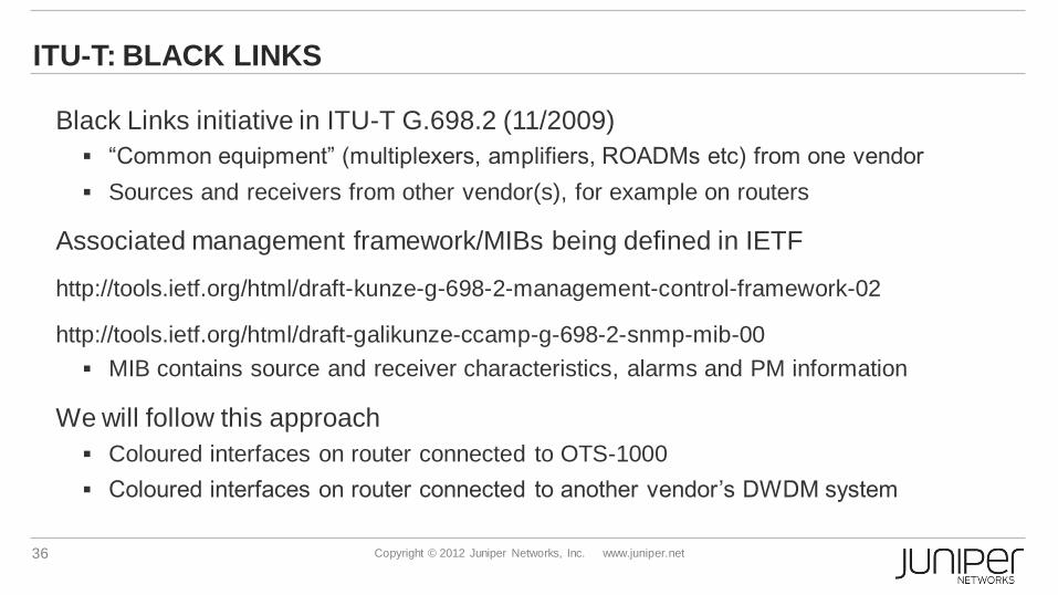
ITU-T: BLACK LINKS
Black Links initiative in ITU-T G.698.2 (11/2009)
“Common equipment” (multiplexers, amplifiers, ROADMs etc) from one vendor
Sources and receivers from other vendor(s), for example on routers
Associated management framework/MIBs being defined in IETF
http://tools.ietf.org/html/draft-kunze-g-698-2-management-control-framework-02
http://tools.ietf.org/html/draft-galikunze-ccamp-g-698-2-snmp-mib-00
MIB contains source and receiver characteristics, alarms and PM information
We will follow this approach
Coloured interfaces on router connected to OTS-1000
Coloured interfaces on router connected to another vendor’s DWDM system
37 Copyright © 2012 Juniper Networks, Inc. www.juniper.net
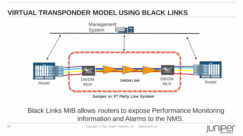
VIRTUAL TRANSPONDER MODEL USING BLACK LINKS
Router DWDM
MUX
100G
DWDM LINK
100G
100G 100G
100G 100G
100G 100G
DWDM
MUX Router
Black Links MIB allows routers to expose Performance Monitoring
information and Alarms to the NMS.
Juniper or 3rd Party Line System
Management
System

ADVANCES IN
MULTICHASSIS
TECHNOLOGY
39 Copyright © 2012 Juniper Networks, Inc. www.juniper.net
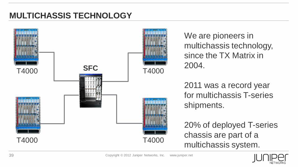
MULTICHASSIS TECHNOLOGY
T1600 TXP SFC T4000
T1600 T4000
T1600 T4000
T1600 T4000
We are pioneers in
multichassis technology,
since the TX Matrix in
2004.
2011 was a record year
for multichassis T-series
shipments.
20% of deployed T-series
chassis are part of a
multichassis system.

40 Copyright © 2012 Juniper Networks, Inc. www.juniper.net
WHY MULTICHASSIS
Non- multichassis capable platform
System capacity is challenged to keep
pace with traffic growth
Create periods of uncertainty
Forces early adoption of higher capacity
line cards
Though the systems might support a
higher capacity with new line
cards/fabric upgrade, slots may not be
available to do the same
Forced upgrade of line cards – reduces
the lifespan of line cards
Increases CAPEX over a period time
Time
Ba
nd
wid
th
Slots filled
Requirement
vs. capacity
gap
System
capacity
growth (Single Chassis)
Multichassis Capacity
41 Copyright © 2012 Juniper Networks, Inc. www.juniper.net
SOME FACTS ABOUT MULTICHASSIS
From the day-to-day operational point of view, not very different to a
single chassis
The system is a single node from the routing protocol point of view
Central “brain” (the RE in the central chassis)
Single point of management
Single config file, just like for a standalone chassis
Seamless slot numbering in config (e.g. “slot 10” rather than
“chassis 2, slot 3”)
When using link aggregation (LAG), member links can be on
different chassis
42 Copyright © 2012 Juniper Networks, Inc. www.juniper.net
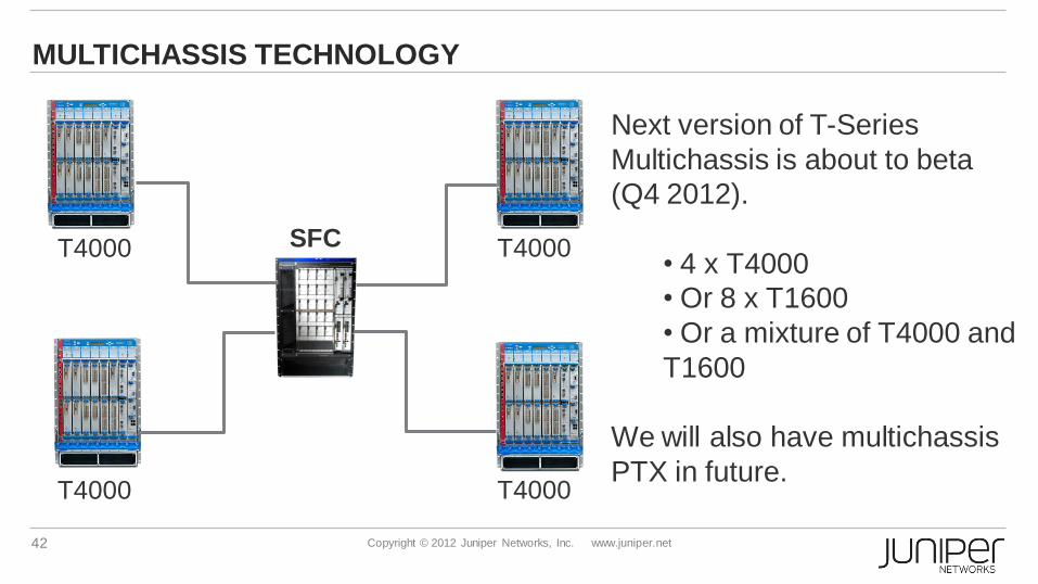
MULTICHASSIS TECHNOLOGY
T1600 TXP SFC T4000
T1600 T4000
T1600 T4000
T1600 T4000
Next version of T-Series
Multichassis is about to beta
(Q4 2012).
• 4 x T4000
• Or 8 x T1600
• Or a mixture of T4000 and
T1600
We will also have multichassis
PTX in future.

43 Copyright © 2012 Juniper Networks, Inc. www.juniper.net
MULTICHASSIS INTERCONNECTS
In all of our multichassis systems, the interconnects
between the chassis are optical
Not possible to have electrical interconnects at these
high data rates over tens of metres
But people have found optical interconnections to be
inconvenient, because of having to clean/inspect large
numbers of optical connectors at installation time
Is there a way of having optical cables, but with the
zero-maintenance attributes of an electrical cable?
44 Copyright © 2012 Juniper Networks, Inc. www.juniper.net
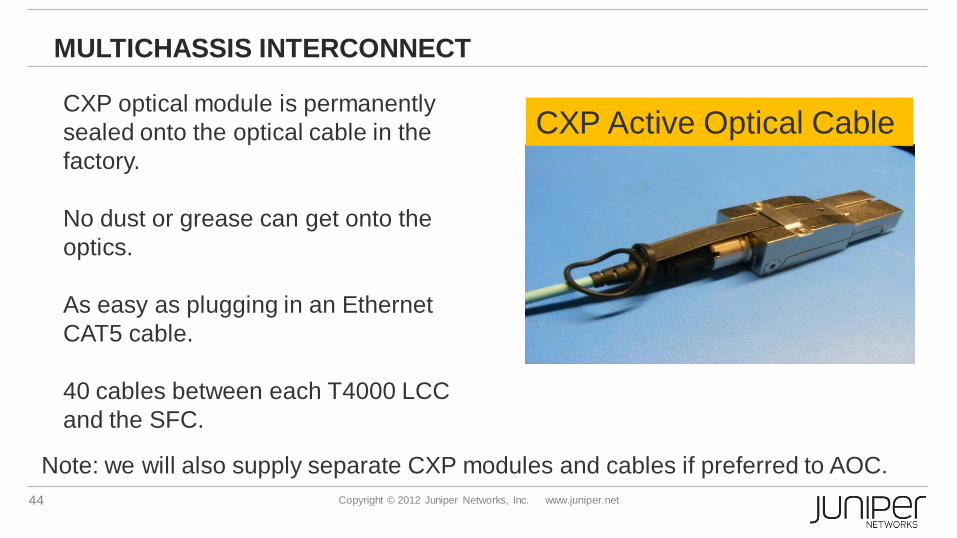
MULTICHASSIS INTERCONNECT
CXP Active Optical Cable CXP optical module is permanently
sealed onto the optical cable in the
factory.
No dust or grease can get onto the
optics.
As easy as plugging in an Ethernet
CAT5 cable.
40 cables between each T4000 LCC
and the SFC.
Note: we will also supply separate CXP modules and cables if preferred to AOC.
45 Copyright © 2012 Juniper Networks, Inc. www.juniper.net
CXP INTERCONNECT
Each CXP cable consists of 24 “lanes” (fibres), 12 in each direction.
We have per-lane power monitoring/reporting.
Spare lane not needed for data used to carry an internal identifier, in
order to detect mis-cabling
Optional mode to make it easier to plug cables into correct sockets on
LCC and SFC.
Red LEDs flash on first pair of ports to be connected.
When they are connected, the LEDs stop flashing. The LEDs from the next
pair of ports start flashing and so on.
46 Copyright © 2012 Juniper Networks, Inc. www.juniper.net
SUMMARY
Advent of PTX: streamlined router for the core.
Highest capacity in the industry
Junos Operating System - extensive protocol and feature support
Optical Integration
commoditisation of optical transmission
Integration of long-haul transponders into the router.
Next generation of multichassis technology