
Advanced System Analysis And Design
94
Table of Contents Questions No: 1.............................................. 1 Introduction............................................... 1 Methodologies Recommendation...............................2 Plan Driven Methodologies.................................2 Advantages................................................6 Disadvantage..............................................6 SSADM is less complicated then SDLC.......................6 It does not include documentation for each steps..........6 SSADM is faster, consume less effort and cost compared to SDLC......................................................6 Error and bugs are harder to be notice because testing is not covered in SSADM......................................6 Unique cross referencing of techniques....................6 Expensive and exhaustive..................................6 Triple Constraints:.......................................7 Analysis on Agile & Plan Driven Methodology...............8 Project Characteristics Analysis..........................8 Alistair Cockburn Polar Graph.............................9 Agile Methodologies......................................10 Most appropriate methodology chosen for the project.......14 Question No:2............................................... 15 Requirement Prioritizing..................................15 Project Summary...........................................17 Project Plan.............................................. 17 Gantt chart..............................................20 Cost Estimation...........................................25 Techniques...............................................25 Question No: 3.............................................. 31
-
Upload
anit-thapaliya -
Category
Education
-
view
2.488 -
download
2
description
Advanced System Analysis & Design, This Document contain different development methodologies description and its advantages & disadvantages based on the requirement of the project. It also includes development constraints in development phase, design document etc.
Transcript of Advanced System Analysis And Design

Table of ContentsQuestions No: 1..........................................................................................................................1
Introduction............................................................................................................................1
Methodologies Recommendation...........................................................................................2
Plan Driven Methodologies................................................................................................2
Advantages........................................................................................................................6
Disadvantage.....................................................................................................................6
SSADM is less complicated then SDLC............................................................................6
It does not include documentation for each steps..............................................................6
SSADM is faster, consume less effort and cost compared to SDLC.................................6
Error and bugs are harder to be notice because testing is not covered in SSADM............6
Unique cross referencing of techniques.............................................................................6
Expensive and exhaustive..................................................................................................6
Triple Constraints:..............................................................................................................7
Analysis on Agile & Plan Driven Methodology................................................................8
Project Characteristics Analysis.........................................................................................8
Alistair Cockburn Polar Graph...........................................................................................9
Agile Methodologies........................................................................................................10
Most appropriate methodology chosen for the project........................................................14
Question No:2..........................................................................................................................15
Requirement Prioritizing......................................................................................................15
Project Summary..................................................................................................................17
Project Plan..........................................................................................................................17
Gantt chart........................................................................................................................20
Cost Estimation....................................................................................................................25
Techniques.......................................................................................................................25
Question No: 3.........................................................................................................................31
Requirement Listing.............................................................................................................31
Functional Requirement.......................................................................................................31
Non-Functional Requirements.........................................................................................35
Architecture......................................................................................................................36
Scope................................................................................................................................38

Network Diagram.............................................................................................................39
Use Case Diagrams..........................................................................................................40
Start Chart Diagrams............................................................................................................50
Sequence Diagram...............................................................................................................51
Collaboration Diagram.........................................................................................................57
Activity Diagrams................................................................................................................60
Entity Relationship Diagram................................................................................................66
Class Diagram......................................................................................................................67
Component Diagram............................................................................................................67
Deployment Diagram...........................................................................................................68
Interface Design...................................................................................................................69
References................................................................................................................................74
Appendix..................................................................................................................................76
List of Figure
Figure 1 Waterfall Model Diagram (Tutorialspoint, 2010).......................................................2Figure 2USDP Diagrams............................................................................................................4Figure 3 SSADM Diagram (Patel , 2008)..................................................................................5Figure 4 Triple Constraints (advncs, 2009)................................................................................7Figure 5 Polar Chart (Cockburn)................................................................................................9Figure 6 Polar Graph based on the Group................................................................................10Figure 7 DSDM Life Cycle......................................................................................................11Figure 8 XP Structure...............................................................................................................12Figure 9 XP Variables & Values..............................................................................................12Figure 10 Gantt Chart Time Box1...........................................................................................21Figure 11Gantt Chart Time Box 2...........................................................................................22Figure 12 Gantt Chart Time Box 3..........................................................................................23Figure 13 Gantt Chart Implementation Iteration......................................................................24Figure 14 MVC Architecture Diagram....................................................................................36Figure 15 MVC architecture of OATS.....................................................................................37Figure 16 Network Diagram OATS.........................................................................................39Figure 17 Use Case Diagram Search & Registration...............................................................40Figure 18 Use Case for flight reservation................................................................................42Figure 19 Use Case Diagram Payment....................................................................................44Figure 20 Use Case Reservation Cancellation.........................................................................45Figure 21 Use Case Manage Flight..........................................................................................47Figure 22 Use Case Delete Flight Details................................................................................48Figure 23 Use Case Generate Report.......................................................................................49Figure 24 Start Chart Diagram of OATS.................................................................................50Figure 25 Sequence Diagram User Login................................................................................51
ii

Figure 26 Sequence Diagram Search Flight.............................................................................52Figure 27 Sequence Diagram Reservation...............................................................................53Figure 28 Sequence Diagram User Registration......................................................................54Figure 29 Sequence Diagram Reservation Cancellation..........................................................55Figure 30 Sequence Diagram Report Generation....................................................................56Figure 31 Sequence Diagram Manage Flight...........................................................................56Figure 32 Collaboration Diagram User Registration...............................................................57Figure 33 Collaboration Diagram Reservation........................................................................57Figure 34 Collaboration Diagram reservation cancellation.....................................................58Figure 35 Collaboration Diagram Manage Flight....................................................................59Figure 36 Collaboration Diagram Member Login...................................................................59Figure 37 Activity Diagram Search Flight...............................................................................60Figure 38 Activity Diagram Reservation.................................................................................61Figure 39 Activity Diagram New Registration........................................................................62Figure 40 Activity Diagram Payment......................................................................................63Figure 41 Activity Diagram Manage Flight.............................................................................64Figure 42 Activity Diagram Generate Report..........................................................................65Figure 43 Activity Diagram reservation cancellation..............................................................66Figure 44 ER Diagram of OATS.............................................................................................66Figure 45 Class Diagram of OATS..........................................................................................67Figure 46 Component Diagram of OATS................................................................................67Figure 47 Deployment Diagram of OATS...............................................................................68Figure 48 Home Page Interface................................................................................................69Figure 49 Login Page Interface................................................................................................70Figure 50 Registration Page Interface......................................................................................71Figure 51 Reservation Page Interface......................................................................................72Figure 52 Manage Flight Interface...........................................................................................73List of Table
Table 1 Category of Methodology.............................................................................................1Table 2 Advantages & Disadvantages of Waterfall Approach..................................................2Table 3 Waterfall Approach Application...................................................................................3Table 4 Bottleneck of waterfall approach for the project..........................................................3Table 5 Advantages & Disadvantage of SSADM (2.docm, 2007)............................................6Table 6 Comparison Agile Vs. Plan Driven based on Application............................................8Table 7 Comparison of Agile Methodologies (AgileOnly, 2012)...........................................14Table 8 Project Plan (DSDM)..................................................................................................17Table 9 Gantt Chart Overall.....................................................................................................20
iii

Acknowledgement
Thanks for all who directly and indirectly helped me a lot in shaping my work to achieve this great extent.
A substantial amount of support for my work was given by Mr Rohit Pandey (Lecturer Department of Computing, Islington College). Without his innovative and excellent supervision this work won’t have been great success, thanks a lot for the support and immense patience.
Likewise, we are very grateful to our each and every group members as well as business partner Mr Manoj Gaire, Mr Ranjit Raj Onta, Mr Karun Lama, Miss Sujata Basnet from Inkwalkar Pvt Ltd. Without their strong advice and suggestion this project can’t be a successful one. Thank You, Guys.
Thanks & Regards
Anit Thapaliya
Manoj Rana
Karun Lama
Mahesh Bhandari
BSc (Hons) Computing
Islington College
iv

Abstract
This document on “Online Airlines Ticketing System” normally describes the introduction, background of Online Airlines Ticketing aspects with the different available development approaches.
Secondly, this document focuses on the comparision different development methodologies and selection of the most appropriate methodology with the position point for justification. Likewise, in the initial phase appropriate plan was generate based on the selected methodology. And also the primary as well as secondary cost estimation for the project was described.
Later in this document the visualization of the project was presented through the different diagrams such as UML, ER etc. Basically ER Diagram is used to present the ideas based on the data store or the database that was required for the online airlines ticketing system. The system overview is presented through the help of the interface design. Interface design usually describes the pictorial presentation of the online airlines ticketing system.
Meanwhile, before the design portion various analysis is carried out in order to sort out the requirement of the online airlines ticketing system. This includes the architecture, scope of the system. The analysis part result to the formation of the software requirement specification for the project. Based on which the design portion of the document is carried out.
This document also reflects the group efforts for the implementation of the online airlines ticketing system. And also reflect the different role performed by the different group members.
v

Questions No: 1
Introduction From the view point of Avison & Fitzgerald (1988) a methodology can be describe as a collection of procedures, techniques, tools, documentation aids etc. organized within a lifecycle structure with an underlying philosophy which capture’s a particular view of the meaning and purpose of information system development. Normally during the software development lifecycle a methodology play a vital role for the better quality software product, better documented software, more consistent software, more maintainable software etc. In other word, a methodology is a set of general principles that guide the choice of a method suited to a specific task or project. The key terms within the methodology are described below.
Method “An instantiation of the principal in a given situation, the step-by-step description of the steps involved in doing a job”.
Task “A task is something we follow in a particular project.” A task might be ‘Analyse the requirement for a use case’
Technique “A technique specifies how to carry out a task.” For Examples, UML Collaboration diagram.
Table 1 Category of Methodology
Plan Driven Methodology (Heavy) Agile Methodology (Light)A Framework that describes the activities performed at each stage of a software development project or the process are managed & controlled in a sequential manner.
Normally these types of methodologies spped up or bypass one or more life cycle phases of software development life cycle and usually less formal & reduced scope.
Examples SSADM, USDP, WATERFALL Examples DSDM, XP SCRUM
Now a day, software development methodologies are categories in two aspect of the development process called Heavy Weight Methodologies (Waterfall, RUP) & Light Weight Methodologies (DSDM, XP, SCRUM etc.). But having the classification in the software development methodologies most of the software company rated the selection of the appropriate methodology is the critical task in their business procedure (Pelican Engineering,2002).
Likewise, a statistical survey on the project delivery and failure in 2009 reflects that the 26 percentage of the all project failed before completion, 30 percentage of the software project was complete on time with the estimated budget allocation but the rest of the project was failed to deliver on time and with the initially estimated budgets (CHAOS, 2009).
1

Hence, the software development process is directly responsible in the selection of the methodologies in order to satisfy the software company reputation as well as quality as acceptable product for the business client.
Methodologies Recommendation
Plan Driven Methodologies
Waterfall Approach:Waterfall approach was first SDLC model to be used widely in software engineering to ensure success of the project. In “Waterfall” approach the whole process of software development is divided into separate phases. In waterfall model, typically, the outcome of one phase acts as the input for the next phase sequentially.
The waterfall model is a sequential software development model. In other word it is defined as a process for the creation of software in which development is seen as flowing steadily downwards like a waterfall in the nature. The origin of the term “waterfall” is cited to be an article by Winston W. Royce. (Rouse, 2007). The unmodified waterfall model progress flows from top to the bottom just like a normal waterfall.
Figure 1 Waterfall Model Diagram (Tutorialspoint, 2010)
Table 2 Advantages & Disadvantages of Waterfall Approach
Advantage DisadvantageVery easy to implement (Linear) Only able to use when requirement are fixed
2

Required minimum resource Unable to move back to the previous stageDocumentation is produced at every stages If mistake happen on middle, should start
from the scratchTesting is done to check code is running correct or not
Tester role only happen in the testing phase
Well understood milestones It is difficult to measure progress within stages
Waterfall Model Application (When to Use?)
Every software development is different and requires a suitable software development life cycle to be followed on the internal and external factors. Some situations are mentioned on the table below:
Table 3 Waterfall Approach Application
S.N:
Suitable Situations
1 The project is short2 Product definition is stable3 Requirements are very well documented, clear and fixed4 Technology is not so dynamic5 No ambiguous requirements
Why not appropriate?
The advantages of waterfall development are that it allows for departmentalization and control. But the waterfall approach is not suitable for the online airlines ticketing system because of the following reasons:
Table 4 Bottleneck of waterfall approach for the project
S.N:
Reasons
1 Cannot accommodate the changing requirement:Missing requirement or the changing requirement cannot accommodate in the waterfall approaches because it required fixed and stable requirement but the features are not known and may change in the future. Hence, it will be difficult to implement the change in the waterfall approaches
2 High amount of risk and uncertainty:The negative aspect of the waterfall model that is does not allow for much reflection or revision. Once in the testing phase it is very difficult to go back and change something in order to mitigate the targeted risk. Hence, it is not suitable for the online airlines ticketing system where requirement are at a moderate to high risk of changing. So, risk
3

and uncertainty is high with the waterfall approach.
RUP/USDP (Rational Unified Process/Unified Software Development Process)Unified software development process is object oriented approach for the software development. USDP introduce the main concepts of iterative and incremental development. USDP has 4 phases (i.e. Inception, Elaboration, Construction and Transition). Iteration are vital to USDP where each iteration is important that includes planning, analysis, design, integration and testing. Additional functionality is implemented in each increment. USDP is an industry standard software development process. It is free & the generic process for the UML. And also USDP is use case and risk driven with architecture centric behaviour.
Rational Unified Process is an instantiation of USDP. RUP is a product marketed and owned by IBM software
Figure 2USDP Diagrams
USDP Application (When to use USDP?)
The main focus of USDP is to accommodate the changing nature of the requirements or the missing requirement of the system in the software development life cycle. USDP is mostly used for big a project that requires heavy documentation.
Why not appropriate?
USDP is generic software development process. It has to be customized for our team project such as our project duration is short but USDP is normally used for the big project which resembles the long duration. As team project online airlines ticketing system development requires a day to progress report based on the project plan. Hence, along USDP is not suitable for the online airlines ticketing system.
4

SSADM (Structured System Analysis and Design Method)SSADM is a procedural and documentation standards methodology for system development. This kind of method is systematic approach to the analysis and design of Information Technology (IT) applications that is commonly used in the UK (Ashworth, 1993).
The methodology adopts the SDLC phases. The steps in SSADM are similar with SDLC, but it does not attempt to cover information strategy planning or construction, testing and implementation of the eventual system (Ashworth, 1993). In developing a system using this methodology, user - analyst interaction is possible because according to this method, the system is belong to the user, hence their participation in the development process is essential.
5

Figure 3 SSADM Diagram (Patel , 2008)
SSADM consists of 5 main modules:
1. Feasibility Study 2. Requirement Analysis 3. Requirement Specification 4. Logical System Specification 5. Physical Design
6

Table 5 Advantages & Disadvantage of SSADM (2.docm, 2007)
Advantages DisadvantageSSADM is less complicated then SDLC It does not include documentation for each
stepsSSADM is faster, consume less effort and cost compared to SDLC
Error and bugs are harder to be notice because testing is not covered in SSADM
Unique cross referencing of techniques Expensive and exhaustive
SSADM Application (When to use SSADM?)
SSADM is suitable for the system development process where the requirements of the project are not known and the project is big in category. SSADM is data driven highly structure with very detailed rules and guidelines which adhered the big project into small. It is also suitable for the big project that requires data modelling and cross referencing for consistency.
Why not appropriate?
Online airlines ticketing system is a normal project the major requirement are already list on the case study. Hence, it does not require the procedural and huge documentation of SSADM. Similarly, online airlines ticketing system is group work so that human resources and time are bottleneck for the SSADM making it unsuitable for projects of a small nature.
Conclusion
Apart from the various methodologies analyzed above however, depending upon the various factors such as project context, human resources, technology & techniques constraints, time etc. these methodologies are not appropriate for online airlines ticketing system development process.
7

Triple Constraints:When it comes to information technology project i.e. an online airlines ticketing system we often struggle to find the balance betweeb scope, cost and project deadline. We believe in a “measure twice, cut once” mentality where appropriate level of analysis and planning can help a project be successful, as well as mitigate problems later in the project development life cycle.
Figure 4 Triple Constraints (advncs, 2009)
Scope:
Scope is the product or services that the software offers. Talking about this case study our scope is to develop an online ticketing system, of course it’s a high scope project due to the critical business task it performed.
Time:
Time/Resource describes the structure of our group and its ability to fulfil commitments or the ability to handle changes. For this online airlines ticketing system the project deadline is before 10th January 2014. Likewise, the maximum human resource allocated was 5 but due to critical problems human resource remains are just 3.
Cost:
Cost reflects the competitive advantage of product and marginal utility & value to the clients. In other word, it’s a pre estimation of the sum of the money required for the software development. During the development of the online airline ticketing system all the direct as well as indirect cost should be mentioned.
8

Analysis on Agile & Plan Driven MethodologyConsider essential software engineering difficulties like complexity, conformity, changeability and invisibility for both the agile and plan driven methodologies.
Agile methodology handles changeability and invisibility by building a shared vision of project’s objectives. But agile do not scale up to large complex project but agile methods found on handling the complexity and some extent of conformity.
Plan driven methodology handle conformity and invisibility by investing in extra documentation. Likewise, they founder on changeability and the increasing complexity due to system integration.
Table 6 Comparison Agile Vs. Plan Driven based on Application
Characteristics Agile Plan DrivenScope Responding to change High assurance & stabilitySize Small Team Large TeamEnvironment High Change; Project
FocusedLow Change; Project/Organization Focused
Project Characteristics AnalysisS.N: Characteristics Agile Plan Driven1 Size (less than 10) Yes No2 Change response (=High) Yes No3 Time (=Short) Yes No4 Culture (=thriving on chaos) Yes No5 Traceability (=High) No Yes6 Growth/Progress (=Visible) Yes No
According to the case study based on the online airlines ticketing’s system, above mention factors may consider as the turning point in order to select the development methodologies. From the above mention table, the case study restricts the project size of more than 4 persons. Hence, the Plan driven methodologies is not suitable for the development of the online airlines ticketing system because the project human resources is fixed at the three different members.
Secondly, the invisible requirement change might occur during the development phase as it is the dynamic system although the basic requirements are fixed. The response rate for change rate must be low in order to flow the plan driven methodologies.
Thirdly, let’s say time, talking about the time for this system is it well declared to be short for plan driven methodologies. As the system need some rapid development procedures.
Fourthly, Culture reflects the nature of the project being the academic project it very comfort and empower via the degree of freedom to the students without the framework of policies and procedures.
9

Lastly, Traceability and growth, for the online airlines ticketing system group members must show the progress with the different members as well as the module leader but the growth or progress is not visible in the plan driven methodologies. Similarly, the traceability is informally prioritized in the agile methodology but in the plan driven methodology it is formally managed where fractional documentation is required. Hence, Agile is suitable for the online airlines ticketing system.
Alistair Cockburn Polar GraphCockburn identified five critical decision factors associated with agile and plan driven methodologies.
Figure 5 Polar Chart (Cockburn)
Personnel
Size
CultureDynamism
Criticality
0
5
10
AgilePlan driven
The above mention diagram, reflects the comparison between the agile and plan driven methodologies. Based on the Cockburn description over the five different axes certain number is provide to each axes in order to calculate the polar graph. The range (1-10) is used to describe the properties of the polar axes according the Cockburn description. Hence, the graph results that agile methodology is suitable for the project enrolling the low human resources.
Polar Graph based on our Group
Personnel scale of the group members is low indicating 3 out of 10 from the personnel axes of the polar graph. Members are not professionally strong. Likewise, the size is low hence it is directed towards the center of the polar graph. Normally the basic requirements are mentioned on the case study but it may change during the project development. Hence, the group cannot accommodate the changes.
10

Figure 6 Polar Graph based on the Group
Personnel
Size
CultureDynamism
Criticality
0
5
10
Agile
Based on the group decision made on the meeting held on the 6 th December 2012 at Brit House, Islington College. Team members decided to apply agile methodology rather than the plan driven heavy methodology for the development of the online airlines ticketing system. This because of the above mentioned analysis results.
Agile MethodologiesAgile software development model is a combination of iterative and incremental process models with focus in process adaptability ad customer satisfaction by rapid delivery of working software product. Agile methods break the product into small increments and these increments provides an ierations. Among the various agile methodologies only DSDM and XP is mentioned below.
DSDM (Dynamic Software Development Method)In January 1994, sixteen individuals from the software development business met to form the DSDM Consortium. This group hoped to establish an independent RAD methodology. The basic concepts of DSDM were established by March, and the consortium now consisted of 36 members. This showcases that the DSDM approach to software development is mature, as it has not undergone any major revisions for several years. As a result, the DSDM Consortium was created and convened in 1994 with the goal of devising and promoting a common industry framework for rapid software delivery.
DSDM is an iterative and incremental approach that incorporates the principles of agile development. It is based on nine key principles that are as follows:
11

Figure 7 DSDM Life Cycle
Principles
The entire approach of DSDM relies on nine principles (DSDM Consortium, 2010), which are applied throughout the entire process. These principles are as follows:
1. Active user involvement2. Teams must be empowered to make their own decisions.3. Frequent delivery of releases is more important than maximizing quality.4. The primary criteria for deliverables is meeting the business needs.5. Iterative development is essential to reach a correct solution.6. Any change during development can be reversed.7. The most high level requirements should be unchangeable.8. Testing shall occur throughout the lifecycle of the project.9. All stakeholders must cooperate and communicate.
MoSCoW
The MoSCoW system is a method of prioritizing items. DSDM utilizes it as a system for prioritizing requirements. This acronym stands for Must, Should, Could, and Would. These are the four types of priorities that requirements may have. Must priorities are those that are absolutely required in order to meet the business needs of the end users. Should priorities are those that the system should have if even remotely possible, but the system will not fail outright if the requirement is not met. Could priorities are those that it would be nice for the system to have, but the quality of the final system will not be affected if these priorities are
12

not met. Lastly, the Would priorities are requirements that could be added at a later time if it is feasible to do so, such as during post-project development.
XP (Extreme Programming)Extreme Programming is a software development process as well as methodology. XP is a lightweight methodology or “Crystal Methodology” according to Alistair Cockburn. In other word methodology of agile family have high productivity and high tolerance. Communication is usually strong with short paths, especially informal not documented. There us only a small range of deliverables but these are delivered frequently.
Figure 8 XP Structure
XP has been applied to business problems only e.g. projects with external customer that wants a specific product. The projects usually ranged from 6 to 15 months? XP was used by small teams ranging from two to twelve members.
Figure 9 XP Variables & Values
XP Variables XP ValuesCost CommunicationTime SimplicityScope FeedbackQuality Courage
13

XP is an iterative and incremental process. The project is divided into smaller “mini projects” which result in an increment of functionality, the so-called release. An XP project creates frequent release in order to gain the values of the feedback.
XP process normally includes the planning games process and the development. The process planning games consists of three steps exploration, planning and steering while the development process usually consists of the iteration of the project releases. But the each iteration in the development process is again begins with an iteration planning game cycle(Dudziak, 1999/2000).
XP is different although the rules and practices are not new they are used in a much more strict fashion. This is especially true for pair programming, refactoring and unit testing. It seems to be more fun than a “traditional” process mostly because there is a strong emphasis on team work, communication and helping each other.
14

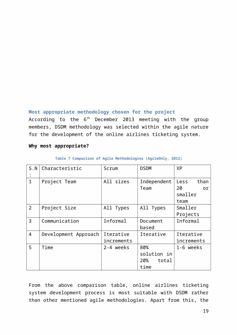
Most appropriate methodology chosen for the projectAccording to the 6th December 2013 meeting with the group members, DSDM methodology was selected within the agile nature for the development of the online airlines ticketing system.
Why most appropriate?
Table 7 Comparison of Agile Methodologies (AgileOnly, 2012)
S.N:
Characteristic Scrum DSDM XP
1 Project Team All sizes Independent Team
Less than 20 or smaller team
2 Project Size All Types All Types Smaller Projects3 Communication Informal Document based Informal4 Development Approach Iterative
incrementsIterative Iterative
increments5 Time 2-4 weeks 80% solution in
20% total time1-6 weeks
From the above comparison table, online airlines ticketing system development process is most suitable with DSDM rather than other mentioned agile methodologies. Apart from this, the change management environment of the DSDM is most suitable aspect for the online airlines ticketing system because the invisible change might occur during the development phase. Likewise, DSDM MosCow technique is very useful for prioritizing the requirements of the project within the fixed time box. Additionally, DSDM ensures the delivery of the project on time. The basic functionality is quickly identified and delivered. In addition, the results/progress of development is visible.
Requirement priority approach is the important factors for the project because the basic requirement of the project is already mentioned. Hence, missing requirement can be adjust in the project because it’s a iterative approach. Likewise, efficient project management is another strong aspect of the DSDM methodology because DSDM focus on frequent delivery of the products. Furthermore, DSDM make possible to break down aspects of the system into smaller components to produce manageable functional increments.
15

Question No:2
Requirement Prioritizing The functional requirements for a system basically describe what the system normally does
(Sommerville, 2011). For the proposed system as per the requirement analysis following
requirements is considered as functional requirements.
MoSCoW (Described earlier in questions no 1)
S.N: Must Have Requirement
1 Tickets Reservation (The system must provide a means to members to reserve the
tickets)
1. Member must logged in in order to make reservation
2. Member must able to make online tickets reservation
2 Member Registration (The system must provide a means for new user registration)
1. System requires members photo and others details for registration
2. User must logged in in order to search, reserve and payment etc
3 Manage Payment (System must provide a means for online payment)
1. Member must be able to make online payment (after confirmation of
reservation)
2. Member must be able to make cash or Cheque payment (within 3 days of
reservation)
3. System must forward e-tickets after the payment
4. System must handle discount of
15% for reservation before 3 months
5% for reservation before 1 months
10% for reservation of age group (below 2 & above 70)
5 Handle Flight information (System must provide a means to add, update & delete
airlines/flights/airports etc. )
1. Administrator must be able to manage airlines/flights/airports details.
2. Administrator must be able to verify the reservation and cancellation of tickets
made by the customers.
6 Handle e-Ticketing (System must allow members to get an online e-tickets)
1. Administrator must send e-ticket to customer on matching their requisites for
reservation.
2. Member must be able to forward the scanned copy of visa/passport for the
16

agency or company.
3. System must generate unique verification code for every ticket
4. Member must be able to cancel the flight reservation.
Should Have Requirements
7 Manage Cancellation of tickets (System should allow members to cancel their
reservation)
System should manage the cancellation by
1. Deducting 25% charge for reservation before 3 months
2. Deducting 35% charge for reservation before 1 month
3. Deducting 15% charge for reservation before 15 before
8 Handle Report (System should allow administrator or the manager to generate and
view report)
1. System should generate reports to keep track of the flow of customer according
to the country/city/airliner
2. Manager should be able to view reports in order to analyze the performance of
airlines/flights/country etc
3. Manager should be able to view analytical reports regarding the seasonal flow
of Nepali nationals.
9 Manage Search (System should provide a means to allow users to search flights)
Could Have Requirements
10 Update Profile (System could have provide a means to allow members to change their
personal information)
Won’t Have Requirement
11 Confirmation
1. System won’t have SMS confirmation system
Project SummaryStart Date: 29th November, 2013 (Based On Group Meeting Minutes)
17

End Date: 10th January, 2014
Total Days: 42 days
TimeBoxing
TimeBox Number Requirements ID Duration1 M1, S1, S3 2 weeks2 L1, L2, L3, M3, S2 2 Weeks3 L5, M2, A1, A2 1 Week
Total days: 35
Project PlanTable 8 Project Plan (DSDM)
Task Name Duration Start FinishTeam Member AllocationMain Roles
Feasibility Study 1 29/11/2013 30/11/2013Karun
Business Case Study 2 01/12/2013 03/12/2013 Anit
Apply MoSCoW 1 04/12/2013 05/12/2013 Manoj
Time Box1 (M1, S1, S3)
Functional Model Iteration 14 06/12/2013 20/12/2013
Identify Functional Prototype 2 06/12/2013 08/12/2013 Karun
Agree Plan 1 09/12/2013 10/12/2013 Karun, Manoj, Anit
Create Functional Prototype 7 11/12/2013 18/12/2013
Finish UML Diagrams (Use Case, Class, Sequence, Activity, Collaboration, State Chart)
3 11/12/2013 14/12/2013 Karun
Finish Logical design (ERD, Normalization, Data design)
3 15/12/2013 18/12/2013 Anit
Finish Interfaces 1 19/12/2013 20/12/2013 Manoj
Review Prototype 4 21/12/2013 25/12/2013 Karun, Manoj, Anit
Time Box2 (L1, L2, L3, M3, S2 )
Functional Model Iteration 14 26/12/2013 09/01/2014
Identify Functional Prototype 2 26/12/2013 28/12/2013 Anit
18

Agree Plan 1 29/12/2013 30/12/2013 Karun, Manoj, Anit
Create Functional Prototype 7 31/12/2013 07/01/2014
Finish UML Diagrams (Use Case, Class, Sequence, Activity, Collaboration, State Chart)
3 31/12/2013 03/01/2014 Manoj
Finish Logical design (ERD, Normalization, Data design)
3 04/01/2014 07/01/2014 Karun
Finish Interfaces 1 08/01/2014 09/01/2014 Anit
Review Prototype 4 10/01/2014 14/01/2014 Karun, Manoj, Anit
Review Prototype 1 15/01/2014 16/01/2014 Karun, Manoj, Anit
Time Box3 (L5, A1, A2, M2)
Functional Model Iteration 7 17/12/2013 24/12/2013
Identify Functional Prototype 1 26/12/2013 27/12/2013 Anit
Agree Plan 1 28/12/2013 29/12/2013 Karun, Manoj, Anit
Create Functional Prototype 4 30/12/2013 03/01/2014
Finish UML Diagrams (Use Case, Class, Sequence, Activity, Collaboration, State Chart)
1 04/01/2013 05/01/2013 Manoj
Finish Logical design (ERD, Normalization, Data design)
1 05/01/2014 06/01/2014 Karun
Finish Interfaces 1 07/01/2014 08/01/2014 Anit
Review Prototype 2 08/01/2014 10/01/2014 Karun, Manoj, Anit
Design and Build Iteration 40 12/01/2014 21/02/2014
Identify Design Prototype 9 12/01/2014 21/01/2014 Manoj
Agree Plan 3 22/01/2014 25/01/2014 Karun, Manoj, Anit
Create Design Prototype 21 26/01/2014 16/02/2014 Karun
Review Design Prototype 7 17/02/2014 24/02/2014 Karun, Manoj, Anit
Implementation 17 25/03/2014 11/04/2014
User Approval and User guidelines
4 25/03/2014 29/03/2014 Manoj
Train Users 4 30/03/2014 03/04/2014 Anit
19
Implement 2 04/04/2014 06/04/2014 Karun
Review Business 7 07/04/2014 14/04/2014 Karun, Manoj, Anit
20

Gantt chartTable 9 Gantt Chart Overall
Feasibility Study
Business Case Study
Time Box1 (M1, S1, S3)
Identify Functional Prototype
Create Functional Prototype
Finish Logical design (ERD, Normalization, Data design)
Review Prototype
Functional Model Iteration
Agree Plan
Finish UML Diagrams (Use Case, Class, Sequence, Activity, Collaboration, State Chart)
Finish Interfaces
Review Prototype
Functional Model Iteration
Agree Plan
Finish UML Diagrams (Use Case, Class, Sequence, Activity, Collaboration, State Chart)
Finish Interfaces
Design and Build Iteration
Agree Plan
Review Design Prototype
User Approval and User guidelines
Implement
29/11/2013 18/01/2014 09/03/2014 28/04/2014
Start DateDuration
Time Box 2
Time Box 3
Time Box 2
Time Box 3
Time Box 1
21

Figure 10 Gantt Chart Time Box1
Functional Model Iteration
Identify Functional Prototype
Agree Plan
Create Functional Prototype
Finish UML Diagrams (Use Case, Class, Sequence, Activity, Collaboration, State Chart)
Finish Logical design (ERD, Normalization, Data design)
Finish Interfaces
Review Prototype
12/6/2013 12/11/2013 12/16/2013 12/21/2013 12/26/2013
Start DateDuration
Time Box 1 (M1, S1, S3)
22

Figure 11Gantt Chart Time Box 2
Functional Model Iteration
Identify Functional Prototype
Agree Plan
Create Functional Prototype
Finish UML Diagrams (Use Case, Class, Sequence, Activity, Collaboration, State Chart)
Finish Logical design (ERD, Normalization, Data design)
Finish Interfaces
Review Prototype
Review Prototype
12/26/2
013
12/31/2
013
1/5/2
014
1/10/2
014
1/15/2
014
1/20/2
014
Start DateDuration
Time Box 2 (L1,L2, L3, M3, S2)
23

Figure 12 Gantt Chart Time Box 3
Functional Model Iteration
Identify Functional Prototype
Agree Plan
Create Functional PrototypeFinish UML Diagrams (Use Case, Class, Sequence, Activity, Collaboration, State
Chart)Finish Logical design (ERD, Normalization, Data design)
Finish Interfaces
Review Prototype
Design and Build Iteration
Identify Design Prototype
Agree Plan
Create Design Prototype
Review Design Prototype
12/17/2013 1/6/2014 1/26/2014 2/15/2014 3/7/2014
Start Date Duration
Time Box 3 (L5, A1, A2, M2)
24

Figure 13 Gantt Chart Implementation Iteration
Design and Build Iteration
Identify Design Prototype
Agree Plan
Create Design Prototype
Review Design Prototype
Implementation
User Approval and User guidelines
Train Users
Implement
Review Business
1/12/2014 2/1/2014 2/21/2014 3/13/2014 4/2/2014 4/22/2014
Start DateDuration
25

Cost EstimationCost estimation is the process of determining the amount of fixed and variable cost (i.e. direct/indirect cost) associated during the development of the system.
Cost estimation includes estimation of:
i. Hardware and software costs.ii. Travel and training costs.
iii. Effort cost
TechniquesThere is no simple way to make an accurate/precise estimation of the effort to develop software. Some popular estimation techniques are as follows:
a) Algorithmic cost modelling.b) Expert Judgement.c) Estimation by analogy.d) Parkinson’s Law.e) Pricing to win.
Technique Used1. Function Point Estimation 2. COCOMO 81 model (Constructive cost model)
Function Point EstimationFunctions points for the proposed system are as follows:
a. Report generation (MIS)b. UIc. Ticketing (Reservation, Payment & Cancellation)
Report Generation
Low Estimate (Sl) = 1500 LOC
High Estimate (Sh) = 2500 LOC
Average Estimate (Sa) = 2000 LOC
Here,
Expected Value (Ev) = (1500+4*2000+2500)/6
= 2000 LOC
26

Now,
Number of person available = 3
Cost per line of code = $1.5 (Assumption)
Total Cost = Total LOC * Cost Per Line of Code
=2000*1.5
=$3000
UI
Low Estimate (Sl) = 1300 LOC
High Estimate (Sh) = 1900 LOC
Average Estimate (Sa) = 1600 LOC
Here,
Expected Value (Ev) = (1300+4*1600+1900)/6
= 1600 LOC
Now,
Number of person available = 3
Cost per line of code = $1.5 (Assumption)
Total Cost = Total LOC * Cost Per Line of Code
=1600*1.5
=$2400
Ticketing (Reservation, Payment & Cancellation)
Low Estimate (Sl) = 1800 LOC
High Estimate (Sh) = 3000 LOC
Average Estimate (Sa) = 2400 LOC
Here,
Expected Value (Ev) = (1800+4*2400+3000)/6
27

= 2400 LOC
Now,
Number of person available = 3
Cost per line of code = $1.5 (Assumption)
Total Cost = Total LOC * Cost Per Line of Code
=200*1.5
=$3600
Total SLOC = 200+1600+2400 = 6000 =6.0 KLOC
Total Cost = $3600+$2400+$3000
= $9000
Now,
28

COCOMO 81COCOMO (Constructive Cost Model) is proposed by DR. Berry Boehm in 1981 normally known as COCOMO 81. It is a regression formula with the data taken from the historical projects as well as current projects. COCOMO II is best for the iterative project like online airlines ticketing system. Normally COCOMO II is classified with the three different software product mentioned below
Organic projects "small" teams with "good" experience working with "less than rigid" requirements
Semi-detached projects "medium" teams with mixed experience working with a mix of rigid and less than rigid requirements
Embedded projects developed within a set of "tight" constraints. It is also combination of organic and semi-detached projects.
The basic COCOMO equations take the form
Effort Applied (E) = a(KLOC)b [ person-months ]
Development Time (D) = c(Effort Applied)d [months]
People required (P) = Effort Applied / Development Time [count]
where, KLOC is the estimated number of delivered lines (expressed in thousands ) of code for project. The coefficients a, b, c and d are given in the following table:
Here online airlines ticketing system comes under the organic project because it consists of the small team with in-house group member’s environment. Hence, the organic software product is suitable for proposed system.
Now we know that:
29

Effort = a(KLOC)^b Person/monthNow,
=2.4*6.0^1.05
=15.75 person/month
Again, for time
=c(Effort)^d month
=2.5*(15.75)^0.38 month
=7.1 months
Similarly, for Person required
=Effort/Time=15.75/7.1
=2.2 person
Now, Cost = 7.1*3*$1000 (where 3=number of members & $1000 is the monthly salary)
Total Cost=$21300
Software cost estimation
S.N. Item Purpose Cost($)
1 Operating System E.g. Windows 7 as a OS platform
200
2 RAD Tools E.g. Dreamweaver, XAMMP or WAMP Server
100
Total $300
Training CostS.N. Item Cost ($)1 Travel Cost 1002 Training Cost 300Total $400
System Hosting Charge
Features SpecificationWeb Space 100GBBandwidth 200MB
30

Domain Registration YesDatabase UnlimitedFTP accounts UnlimitedTotal $2000 (Approx.)
31

Question No: 3
Requirement Listing
Functional RequirementID User Requirements ID System RequirementsL1 The system must provide means to
search flight detailsL1.1 The airlines administrator should be
provided with the facility to manage flight details (insert/update/delete).
L1.2 The database in updated with each task (insert/update/delete).
ID User Requirements ID System RequirementsL2 The system must provide the
means for registration in order to make reservation
L2.1
The system should be provided with an interface for new member registration.
L2.2
Register member is uniquely identified by a ID number.
L2.3
The system should be provided with a facility to modify and delete old member details.
L2.4
Database is updated.
ID User Requirements ID System RequirementsL3 The system shall provide a means
for members to upload or send the VISA/Passport for booking.
L3.1 The members should be provided with an interface for uploading purOATS e.
L3.2 The details are stored in the database
32

ID User Requirements ID System RequirementsL4 The system shall provide a means
to send the confirmation of the reservation.
L4.1 The administrator should be provided with a facility to check the condition of a reservation.
L4.2 If the conditions are matched then reservation details is stored in the database
L4.3 The members should be provided with a soft copy of the reservation confirmation
ID User Requirements ID System RequirementsL5 The system shall provide a means
to cancel the reservation of the flight.
L5.1 The airlines administrator should be provided with a facilities to cancel the reservation based on the policy
L5.2 Database is updated after the cancellation of the reservation
ID User Requirements ID System RequirementsM1 The system could have provided
the administrator with the facilities to manage (insert/update/delete) airlines, flight and airports.
M1.1 The administrator should be provided with an interface to manage airlines, flights, airports.
M1.2 The database is updated after each operations
33

ID User Requirements ID System RequirementsM2 The system could have provided
a means to the administrator to manage (verify) the reservation & cancellation of tickets.
M2.1 The administrator should be provided with an interface to verify reservation & cancellation.
M2.2 The database is updated after each operations
ID User Requirements ID System RequirementsM3 The system could have provided
a means to forward the e-tickets to the members.
M3.1 The administrator should be provided with a facility to send the e-tickets to the members after meeting all the requisites.
M3.2 A confirmation message should be displayed to the administrator interface when the e-ticket is sent.
ID User Requirements ID System RequirementsA1 The system shall provide a
means to see the report based on different factors ticketing operation.
A1.1 The administrator should be provided with a facility to view report.
A1.2 The system should generate report about different operations performed for airline ticketing.
A1.3 The manager should be able to view the generated report.
A1.4 Reports are stored in the database
34

ID User Requirements ID System RequirementsA2 The system shall provide a
means to view reports regarding seasonal flow of Nepali nationals.
A2.1 The system should generate reports regarding seasonal flow of Nepali nationals.
A2.2 The administrator/manager should be able to view the report.
A2.3 Reports are stored in the database
ID User Requirements ID System RequirementsS 1 The system shall operate in online
status.S 1.1 The user should be able to access
the system through internet.S 1.2 The system should be available
anytime
ID User Requirements ID System RequirementsS 2 The system shall print unique
verification code for each e-ticket.S 2.1 The system should generate
unique verification code for each e-ticket.
S 2.2 The unique verification codes are stored in the database.
ID User Requirements ID System RequirementsS 3 The system shall complete registration
with user photo.S 3.1 The system verifies if the user
has uploaded a photo or not.S 3.2 User details along with photo are
stored in the database.
35

Non-Functional RequirementsNon-functional requirements describe the different sorts of requirements that is required for the smooth and proper functioning of the OATS. Certain requirements are mentioned below.
i. Performance Requirements: It specifies the timing characteristics of the software. There are certain features, which are more time-sensitive than others. The non-functional requirements should identify those software functions, which have some constraints on their performance.
1) Response Time: It specify the response time for the transaction in the system. Normally the OATS system can handle mostly 4/5 transaction with the CPU usage of 60%
2) Notification Time: It defines the time required to notify the user about the completion, error in the transaction.
3) Recovery Time4) Loading or Run Time (Application Loading should not take long time).
ii. Safety & Security RequirementsIt specifies the ability of the software to remain protected from unauthorized access. This includes both change access and view access.
1) Authentication system will used for the secure password validation2) Safe Login & Logout will be done by session handling
iii. Other Software Quality Attributes
1) User Friendliness: The system should be ease and simple to use for the end users. It doesn’t require extra training to use the system.
2) Reliability: The OATS System should be reliable because it handles the strong username and password authentication mechanism.
3) Scalability: The system should be scalable as the OATS system should handle the growing amount of work.
4) Fault Tolerant: In case power failure system should able to recover the data using the backup mechanism as well as transaction logs
5) Operating Platform: The OATS system should operate of the computer having the Microsoft Windows Xp and greater, with minimum 1GHz processor and 256MB RAM.
36

6) Interface Metaphor: The OATS system GUI must include the dialog boxes, menus, buttons and also some screen instructions. And minimize the use of pointer navigation then the keyboard navigation.
7) Ease of Use: The OATS system must be user friendly in terms with ease menu, instructions etc.
ArchitectureThe online airlines reservation system development follows the model view architecture. The overview of the system is described in the below figure:
Figure 14 MVC Architecture Diagram
Model-View-Controller is the concept introduced by Smalltalk’s inventors of encapsulating some data together with its processing (the model) and isolates it from the manipulation (the controller) and presentation (the view) part that has to be done on a User Interface (Connelly,2003).
37

Figure 15 MVC architecture of OATS
38

ScopeAn online ticketing system is generally focus on the management of business procedures carried out by the travel agency. OATS usually handles the reservation and payment of the different flight tickets. Members have the facilities to search reserve and purchase the flight tickets. Likewise, the manager has the facilities to generate the different categories report. Normally the overall business activities of the travel agency is wisely handle by the OATS though having minor consideration on the functions like mobile ticketing, etc. The major features that OATS handle were mentioned below:
Customer registration
Make reservation/payment online
Cancel reservation
MIS Reporting
39

Network DiagramFigure 16 Network Diagram OATS
40

Use Case DiagramsFigure 17 Use Case Diagram Search & Registration
Actors: Customer (Primary/Initiator), System
Purpose: Request for the new membership
Overview: The customer search the suitable flight. Then, proceed towards the online form and submits. The system checks if any new membership requests have arrived. The System reviews the membership request and checks the details if the one who applied had meet all the requisites. Then the system stores the new membership details in to the database.
Type: Primary, essential
41

Dialogue
Actor System1. Customer submits the online form for the new membership.
2.The system checks the membership requests from the customer4. The System review the membership request to confirm if all the requisites are matched.5. The system provides the membership6. The system stores the new membership details into the database.
42

Figure 18 Use Case for flight reservation
Actors: Member (Primary/Initiator), System and Administrator
Purpose: Reserve flight
Overview: The member logs in to the system with his/her username and password. Dashboard is displayed in the system where user can do search for the flight suitable for him/her. The system displays a list of flight which the user searched for. The user selects the flight details. The system checks whether the reservation is available or not. The system and the
43

Administrator verify the reservation. The Administrator conforms the reservation with the system generated unique verification code a reservation and send e-tickets to the members.
Type: Primary, essential
Dialogue
Actor System1. The member logs into the system with username and password
4. The member search the flight details6. the member select the flight for reservation
10. The Administrator reserve the flight
2. Authenticates user3. Displays reservation interface
5. Displays the search result
7. Checks the availability of the flight8. Checks all the requisites9. Confirm reservation11. Sends a unique verification code
Alternate Action.
Line 2: If the username and password is not valid then the system rejects logging in.
Line 4: If the flights are not available which are searched by the members then the booking is cancelled.
Line 9: If the member cannot meet all the requisites then reservation cancelld.
44

Figure 19 Use Case Diagram Payment
Actors: Member (Primary/Initiator), System
Purpose: Make Payment
Overview: The member logs into the system and the system displays the dashboard. The members make the reservation for the flight. Members provide the payment. The system checks the discount scheme and deduct from the payment methods applied by the customer.
Type: Primary, essential
Dialogue
Actor System1. The members logs into the system with his/her username and password3. The members make the reservation
2. Displays the dashboard4. The system confirms the reservation of the flight
45

5. The members makes the payment 4. The system checks the discount scheme and deduct the amount from the cards
Alternate Action.
Line 4: While making cash payment the secondary actor may be the administrator but while online payment the actor will be the system itself.
Figure 20 Use Case Reservation Cancellation
Actors: Member (primary/initiator), Administrator
Purpose: To cancel the reservation.
Overview:
46

The member logs into the system and view reservation details. If the members cancel his/her earlier reservation then request for cancellation. The system verify the reservation and allocate the charge amount for the members based on the cancellation scheme and updates the database.
Type: Primary, essential
Dialogue
Actor System1 The member login in to the system.
3. The member request for reservation cancellation.
2. The system authenticates the user.
4. The Administrator verifies the reservation and allocates the cancellation charge to the members.
5. The system updates the database.
47

Figure 21 Use Case Manage Flight
Actors: Administrator (primary/initiator), System
Purpose: Add & update flight details.
Overview:
The administrator login into the system and view the flight details. The administrator can modify, add or delete the flight details. The system updates the update the flight details accordingly.
48

Type: Primary, essential
Dialogue
Actor System1 The administrator login in to the system.
3. The administrator manage the flight details (add, update tasks).
2. The system authenticates the administrator.
4. The System verifies the change.
5. The system updates the database.
Figure 22 Use Case Delete Flight Details
Actors: Administrator (primary/initiator), System
Purpose: To delete flight details.
Overview:
The administrator login into the system and view the flight details. The administrator cselect the delete flight details. The system updates the update the flight details accordingly.
Type: Primary, essential
Dialogue
Actor System
49

1 The administrator login in to the system.
3. The administrator deletes the flight details.2. The system authenticates the administrator.
4. The System verifies the change.
5. The system updates the database.
Figure 23 Use Case Generate Report
Actors: Manager (primary/initiator), System
50

Purpose: To generate report based on different factors
Overview:
The manager login into the system and generate different report based on the flight, country, airlines and city. The manager analyse the report through the analytical report of the seasonal customer.
Type: Primary, essential
Dialogue
Actor System1 The manager login in to the system.
3. The administrator generates the report.2. The system authenticates the manager.
4. The System provides the analytical report.
5. The system updates the database.
Start Chart DiagramsFigure 24 Start Chart Diagram of OATS
51

Sequence DiagramFigure 25 Sequence Diagram User Login
52

Figure 26 Sequence Diagram Search Flight
Figure 27 Sequence Diagram Reservation
53

Figure 28 Sequence Diagram User Registration
54

Figure 29 Sequence Diagram Reservation Cancellation
Figure 30 Sequence Diagram Report Generation
55

Figure 31 Sequence Diagram Manage Flight
Collaboration DiagramFigure 32 Collaboration Diagram User Registration
56

Figure 33 Collaboration Diagram Reservation
Figure 34 Collaboration Diagram reservation cancellation
57

Figure 35 Collaboration Diagram Manage Flight
Figure 36 Collaboration Diagram Member Login
58

Activity DiagramsFigure 37 Activity Diagram Search Flight
59

Figure 38 Activity Diagram Reservation
60

Figure 39 Activity Diagram New Registration
61

Figure 40 Activity Diagram Payment
62

Figure 41 Activity Diagram Manage Flight
63

Figure 42 Activity Diagram Generate Report
64

Figure 43 Activity Diagram reservation cancellation
Entity Relationship DiagramFigure 44 ER Diagram of OATS
65

Class DiagramFigure 45 Class Diagram of OATS
Component DiagramFigure 46 Component Diagram of OATS
66

Deployment Diagram Figure 47 Deployment Diagram of OATS
67

Interface DesignFigure 48 Home Page Interface
68

Figure 49 Login Page Interface
69

Figure 50 Registration Page Interface
70

Figure 51 Reservation Page Interface
71

Figure 52 Manage Flight Interface
72

References2.docm. (2007). Systems Analysis and Design. Retrieved Jan 8, 2014, from
http://www2.docm.mmu.ac.uk/STAFF/M.Stanton/SAD/Tutorials/Lecture1.html
advncs. (2009). Advanced Network & Computer Services. Retrieved from http://www.advncs.com/Content.aspx?ID=11
AgileOnly. (2012). Comparison of Agile Methodology. Retrieved 01 08, 2014, from http://agile-only.com/master-thesis/software-dm/agile-s-dm/c-of-am
Ashworth. (1993). SSADM.
CHAOS. (2009). Standish 2009 CHAOS Report.
Clifton, M., & Dunlap, J. (2003). What Is DSDM? Retrieved December 30, 2013, from http://www.codeproject.com/Articles/5097/What-Is-DSDM
COCOMO II. (2004). Retrieved 01 08, 2014, from http://csse.usc.edu/tools/COCOMOII.php
Connelly, B. (2003). Model View Controller. Retrieved January 8, 2014, from http://c2.com/cgi/wiki?ModelViewController
DSDM Consortium. (2010). Enabling Business Agility. Retrieved 01 07, 2013, from http://www.dsdm.org/version4/2/public/default.asp
Dudziak, T. (1999/2000). Xp "An Overview".
MountainGoat. (2005). SCRUM AND FIXED PRICE: IMPOSSIBLE? Retrieved January 6, 2013, from http://glenndejaeger.wordpress.com/category/software-development/methodology/scrum/
Patel , D. (2008). Methodologies and Lifecycles. New Delhi, India.
Pelican Engineering. (2002). The Software Development Life Cycle.
Rouse, M. (2007). What is waterfall model? - Definition from WhatIs.com. Retrieved 11 26, 2013, from http://searchsoftwarequality.techtarget.com/definition/waterfall-model
Sommerville, I. (2011). SOFTWARE ENGINEERING (Ninth Edition ed.). Noida, India: Dorling Kindersley Pvt. Ltd.
SpringSource. (n.d.). 15. Web MVC framework. Retrieved january 12, 2013, from http://static.springsource.org/spring/docs/3.0.x/spring-framework-reference/html/mvc.html
stanton. (2007). Systems Analysis and Design Lecture 1. Retrieved December 30, 2013, from http://www2.docm.mmu.ac.uk/STAFF/M.Stanton/SAD/Tutorials/Lecture1.html
73

tutor. (2011). Waterfall Model. Retrieved January 5, 2013, from http://www.sdlc.ws/waterfall-model/
Tutorialspoint. (2010). Software Development Life Cycle (SDLC).
versionone. (n.d.). Agile Methodologies for Software Development. Retrieved January 8, 2013, from http://www.versionone.com/Agile101/Agile-Development-Methodologies-Scrum-Kanban-Lean-XP/
Webmaster. (n.d.). Development Methodologies. Retrieved January 3, 2013, from http://www.technologyuk.net/computing/sad/methodologies.shtml
74

AppendixTeam Structure
During the project development the following members are responsible in the different
professional roles with the member’s profile. But the members are very much responsible for
the corresponding roles as well as.
Role: Project Manager
Name: Anit Thapaliya
Abbreviation: AT
Address: Sukedhara, Kathmandu, Nepal
Telephone: 9849054113
Email: [email protected]
Role: Analyst
Name: Manoj Rana
Abbreviation: MR
Address: Bhaktapur, Nepal
Telephone: 9818313739
Email: [email protected]
Role: Designer
Name: Karun Lama
Abbreviation: KL
Address: Gaushala, Kathmandu
Telephone: 9801213225
Email: [email protected]
Role: Testing
Name: Mahesh Bhandari
Abbreviation: MD
Address: Bhaktapur, Nepal
Telephone:
Email:
75


