ADVANCED SOLAR CONTROLLER
42
ADVANCED SOLAR CONTROLLER
Transcript of ADVANCED SOLAR CONTROLLER

ADVANCED SOLAR CONTROLLER
2
WARNING
Always disconnect the power supply before installing or servicing. Read through these warnings and all installation instructions before beginning installation. Failure to do so can result in fire, shock, property damage, personal injury and/or death. Installation, operation, and maintenance must be performed by qualified personnel, in accordance with applicable codes, standards, and practices. SolarHOT, Inc. is not responsible for any damages or injuries that result from improper installation, modification, use or applications/configurations other than those detailed in this document. This control is designed to be mounted indoors; it is neither splash- nor drip-proof and should be protected from extremes in temperature and humidity.
KEEP THIS INSTRUCTION MANUAL AND MAKE IT AVAILABLE FOR ALL END USERS.

3
Main and Technical Features ---------------------------------- Page 5 Display ---------------------------------- Page 6
1 Service Menu ---------------------------------- Page 7 1.1 Language 1.2 Time & Date 1.3 US Version 1.4 System ---------------------------------- Page 8
1.4.1 System 1 1.4.2 System 2 1.4.3 System 3 1.4.4 System 4 ---------------------------------- Page 9 1.4.5 System 5 1.4.6 System 6 1.4.7 System 7 ---------------------------------- Page 10 1.4.8 System 8
1.5 Extra function ---------------------------------- Page 11 1.5.1 Thermostat 1.5.2 Cooling 1.5.3 Anti-stagnation ---------------------------------- Page 12 1.5.4 Diffcontrol ---------------------------------- Page 13 1.6 External Sensor ---------------------------------- Page 14 1.7 Protection function 1.7.1 Cooling ---------------------------------- Page 15
1.7.1.1 Recooling 1.7.2 Overheat protection 1.7.3 Freeze Protection
1.8 Sensor Options ---------------------------------- Page 16 1.8.1 Impulse Flow meter 1.8.2 Grundfos Flow Sensor (GDS1) 1.8.3 Grundfos Flow Sensor (GDS2) ----------------------- Page 17 1.8.4 Flow Monitoring ---------------------------------- Page 18 1.9 Energy Measurement 1.9.1 Warm Sensor ---------------------------------- Page 19 1.9.2 Cold Sensor 1.9.3 Flow 1.10 Pump P1 ---------------------------------- Page 20 1.11 Pump P2 1.12 Glycol ---------------------------------- Page 21 1.13 Glycol Mix 1.14 Reset to Factory default settings 1.15 Reset Op Time ---------------------------------- Page 22 1.16 Time Graph temperatures 1.17 Time Graph operation 1.18 Calibration of Sensors 1.19 Priority Tank ---------------------------------- Page 23
2 Setting Menu ---------------------------------- Page 24 2.1 Maxtemp tank1 2.2 dTMax tank1
2.3 dTMin tank1 2.4 Maxtemp tank2
2.5 dTMax tank2 2.6 dTMin tank2
TABLE OF CONTENTS

4
2.7 Mintemp Prio tank ---------------------------------- Page 25 2.8 Min rev pump 2.9 dTMax return ---------------------------------- Page 26 2.10 dTMin return
2.11 dT FS: Full Speed 2.12 Mintemp Collector
2.13 Delay P2 Extra Functions 2.14 Thermostat function ---------------------------------- Page 27 2.14.1 Start 2.14.2 Hysteresis 2.15 Cooling function ---------------------------------- Page 28 2.15.1 Cooling Start 2.15.2 Cooling Hysteresis 2.16 Anti-stagnation ---------------------------------- Page 29 2.16.1 Start 2.16.2 Stop 2.16.3 Output option 2.17 Diffcontrol function ---------------------------------- Page 30 2.17.1 Max cold tank (no auxiliary heat source) 2.17.2 Min warm tank (no auxiliary heat source) 2.17.3 Max cold tank (w/auxiliary heat source) 2.17.4 Min warm tank (w/auxiliary heat source) 2.17.5 dTMax 2.17.6 dTMin
3 Operation Menu ---------------------------------- Page 31
3.1 Automatic and Off operation 3.2 Manual testing operation
4 Operation Hours Menu ---------------------------------- Page 32 4.1 SD Card option ------------------------------------ Page 33
4.1.1 Initializing the SD Card 4.1.2 Configuring/Changing your system settings ----- Page 34 4.1.3 Using the DataViewer software 4.1.4 Transferring data from the PC to the Control ---- Page 35 4.1.5 Viewing graphs of system data 4.1.6 Backup --------------------------------------------- Page 36 4.1.7 Exporting to Excel 4.1.8 Send by Outlook Express & Export all Zip 4.1.9 Savings File: Save & Savings File: Load
5 Temperatures Menu ---------------------------------- Page 37 6 Special Functions ---------------------------------- Page 38
6.1 Pump exercise function 6.2 Dimmer function
6.3 Security function Appendix A Ohm to °F Conversion Chart for PT1000 Sensors Page 39 Appendix B Pump Functions by System ----------------------- Page 40 Appendix C Controller Schematic ----------------------- Page 41 Warranty ------------------------------------ Page 42

5
• Large graphic display with backlight • Easy to use interface (4 keys with scroll menu) • Several languages available • System set-up/configuration option using SD card • Record and view system data (Energy, pump operation etc.) with SD card interface • Graphic view for temperature, energy etc. • 8 system configurations with several extra functions possible • 5 Temperature sensors (PT1000 type) • 2 Pump outputs (Standard or variable speed) • 2 Analog Grundfos sensor inputs (Flow and Pressure) • 1 Impulse flow meter input (for energy measurement) • Pump exercise function • 1 Extra output (to control back-up heat, heat dump…) • Automatic, Off or Manual Test mode • Monitors system for errors (short or open circuits to sensors, pump failure) • Choice of collector sensor location (external or internal to collector) • Collector protection (Freeze, Over heat, and Anti-stagnation) • Permanent memory storage
Ambient temperature range for normal operation 32°F – 122°F Electrical Protection Installation Category Pollution Degree
IP20 II 2
Fuse Power supply Maximum Power Consumption (with all outputs activated)
5A 120Vac ( 5x20mm) 120Vac +/- 10% 60Hz 4.2A (~504W)
Outputs: P1 (Main pump with standard or PWM speed regulation): P2 (Pump with standard or PWM speed regulation, Booster pump, valve): *NOTE: Combined output of P1 and P2 not to exceed 3A. P3 (Extra, Additional heat, cooling…)
Triac 1.8A* 120VAC. Triac 1.8A* 120VAC Relay 2A 120VAC
Inputs: T1 (Collector1): T2 (Tank1): T3 (Extra sensor): T4 (Extra sensor, Tank2, Collector2): T5 (Collector supply): T6 (Flow meter): GDS1 (Grundfos Flow meter): GDS2 (Grundfos Pressure sensor):
PT 1000 type PT 1000 type PT 1000 type PT 1000 type PT 1000 type Impulse type (low voltage 5V) Analog type (Grundfos VFS) Analog type (Grundfos VPS)
Sensors delivered: 1 Collector sensor 1 Tank 1 Extra
PT1000 (1.5M 356°F) PT1000 (3M 221°F) PT1000 (3M 221°F)
Software version Displayed during the start-up Version xxxxxx
Features
Technical Features

6
Main Display
Circulation direction
Pump Activation indicator
NOTE: System 4 shown in example; features typical of all systems. 1: Simplified drawing of the installation.
- The pump symbols turn when pumps are activated. - The filled triangles on the valve symbol indicate the circulation direction
2: Solar storage is working. 3: SD card storage is active. 4: Sensor temperature readings, pump speed indicators, power and stored energy levels. A: Keypad description
Navigation key up or plus key Navigation key right Navigation key down or minus key Navigation key left
Main menu:
Press to enter the Navigation Menu. (The active menu is highlighted in black at the top of the display) Use the or buttons to navigate in the menus. The selection cursor () will indicate the current submenu. Press to enter the selected menu and/or to return to the previous menu. Not all submenus, selections, or options discussed in this manual are available on all systems. Depictions of menus and submenus shown here are representative of their actual appearance on the control when the same series of settings as is described is followed.
DISPLAY (Screen, Keys, Menus)
4
1 2 3
T1_ _ _°F T2_ _ _°F T3_ _ _°F T4_ _ _°F
P1_ _ _ %
_ _ _ BTU/h _ _ _ BTU
T1 T4
T2
T3
A
SD
Information n Service Settings
Operation Operation h Temperatures
IMPORTANT NOTE: The factory default setting on the Operation Menu is OFF. This prevents system components (P1, P2, P3) from operating until system is set up. To turn on the system, change the setting to AUTOMATIC (Active). See Operation menu / 3.1 for further info.
7
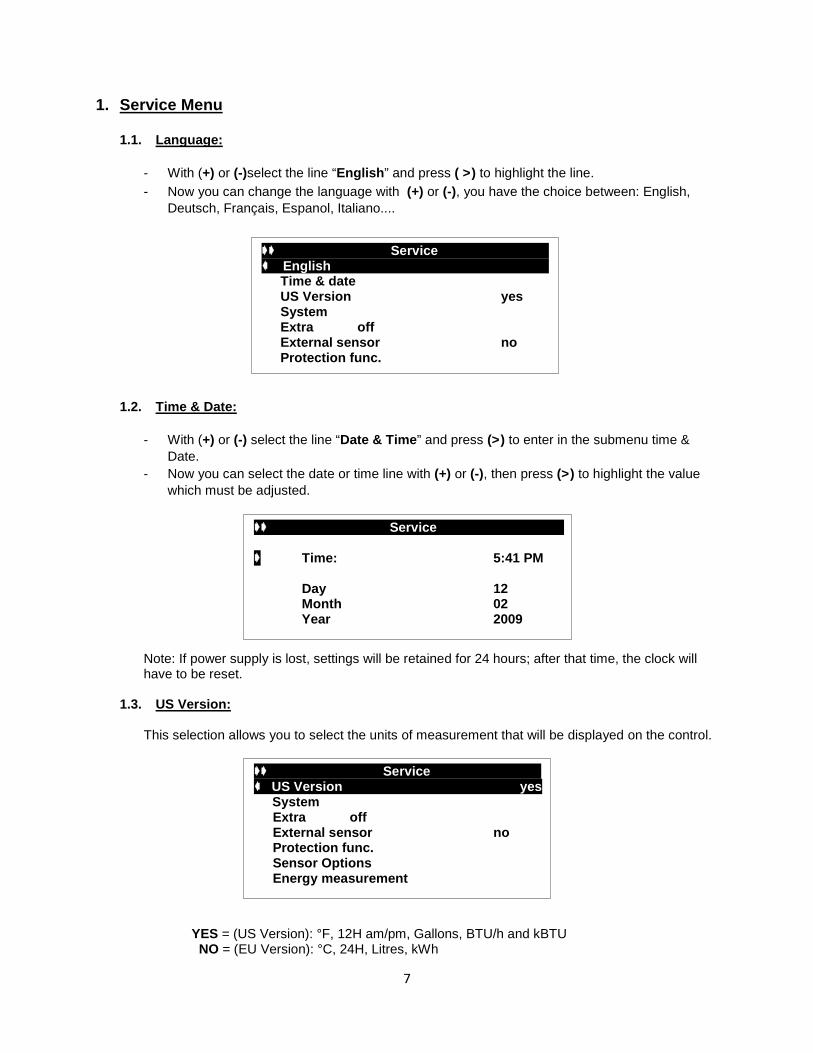
1. Service Menu 1.1. Language:
- With (+) or (-)select the line “English” and press ( >) to highlight the line. - Now you can change the language with (+) or (-), you have the choice between: English,
Deutsch, Français, Espanol, Italiano....
1.2. Time & Date:
- With (+) or (-) select the line “Date & Time” and press (>) to enter in the submenu time &
Date. - Now you can select the date or time line with (+) or (-), then press (>) to highlight the value
which must be adjusted.
Note: If power supply is lost, settings will be retained for 24 hours; after that time, the clock will have to be reset.
1.3. US Version:
This selection allows you to select the units of measurement that will be displayed on the control. YES = (US Version): °F, 12H am/pm, Gallons, BTU/h and kBTU NO = (EU Version): °C, 24H, Litres, kWh
Service English - - --
Time & date US Version yes System Extra off External sensor no Protection func.
---------Service -
Time: 5:41 PM Day 12 Month 02 Year 2009
Service US Version yes y System
Extra off External sensor no Protection func. Sensor Options Energy measurement

8
1.4. System:
When the line is selected, press (>) to enter the submenu. You have the choice between 8 systems with the option to add an extra function (see 1.5).
1.4.1. System 1
Basic system, with 1 tank, 1 pump, 1 collector array and 2 sensors. With this system you can add extra functions with 1 or 2 sensors (Booster pump, Thermostat, Cooling, Anti-stagnation, or Diffcontrol function).
1.4.2. System 2
System with 2 tanks, 1 pump, 1 valve, 1 collector array and 3 sensors. With this system you can add an extra function with 1 sensor (Thermostat, Cooling, or Anti-stagnation function).
1.4.3. System 3
System with 2 tanks, 2 pumps, 1 collector array and 3 sensors. With this system you can add an extra function with 1 sensor (Thermostat, Cooling, or Anti-stagnation function).
System
1
T1
T2
T1 _ _ _°F T2 _ _ _°F P1 _ _ _ %
System 2
T1
T1 _ _ _°F T2 _ _ _°F T4 _ _ _°F P1 _ _ _ %
T2 T4
1 2
P1 P2
System 3
T1
T1 _ _ _°F T2 _ _ _°F T4 _ _ _°F P1 _ _ _ % P2 _ _ _ %
T2 T4
1 2

9
1.4.4. System 4
System with 1 tank, 1 pump, 1 valve, 2 collector arrays with 2 different cardinal directions (East / West) and 3 sensors. With this system you can add an extra function with 1 sensor (Thermostat, Cooling, or Anti-stagnation function).
1.4.5. System 5
System with 1 tank, 2 pumps, 2 collector arrays with 2 different cardinal directions (East / West) and 3 sensors. With this system you can add an extra function with 1 sensor (Thermostat, Cooling, or Anti-stagnation function).
1.4.6. System 6
System with 1 tank, 1 pump, 1 collector array, 1 valve (to be used in an incorporated radiant heating system), and 4 sensors. With this system you can add an extra function with 1 sensor (Thermostat, Cooling, or Anti-stagnation function).
System 4
T1 T4
T2
T1 _ _ _°F T2 _ _ _°F T4 _ _ _°F P1 _ _ _ %
P2 P1
System 5
T1 T4
T2
T1 _ _ _°F T2 _ _ _°F T4 _ _ _°F P1 _ _ _ % P2 _ _ _ %
10
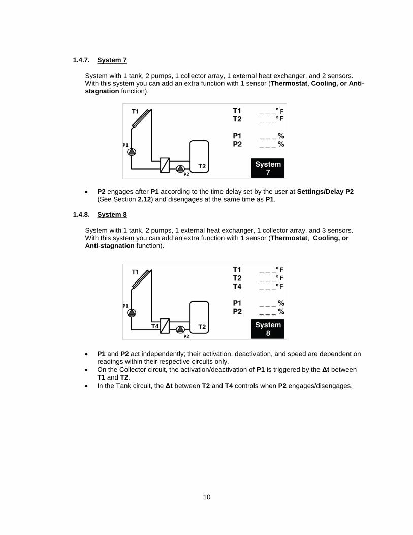
1.4.7. System 7
System with 1 tank, 2 pumps, 1 collector array, 1 external heat exchanger, and 2 sensors. With this system you can add an extra function with 1 sensor (Thermostat, Cooling, or Anti-stagnation function).
• P2 engages after P1 according to the time delay set by the user at Settings/Delay P2 (See Section 2.12) and disengages at the same time as P1.
1.4.8. System 8
System with 1 tank, 2 pumps, 1 external heat exchanger, 1 collector array, and 3 sensors. With this system you can add an extra function with 1 sensor (Thermostat, Cooling, or Anti-stagnation function).
• P1 and P2 act independently; their activation, deactivation, and speed are dependent on readings within their respective circuits only.
• On the Collector circuit, the activation/deactivation of P1 is triggered by the Δt between T1 and T2.
• In the Tank circuit, the Δt between T2 and T4 controls when P2 engages/disengages.
P1
P2
P2
P1

11
1.5. Extra Functions
When the line is selected, press (>) to highlight the line. You have the choice of 4 extra functions; not all options are available on all systems.
1.5.1. Thermostat Function
This function may be used to connect an auxiliary or back-up heat source to your system. Some possible auxiliary heat sources: - Pump controls for Fuel or Gas burner (P3 provides 120V signal)… - Electrical element inside the solar tank. NOTE: If electrical usage exceeds rated capacity of P3 (2A maximum) an external relay must be used.
Example:
This function is available only if selected on the Extra Menu
1.5.2. Cooling Function
The cooling function may be used to cool down the primary solar tank during times of high solar irradiation. This function allows for the accumulation of excess energy in another heat storage area/device (Swimming pool, additional tank or heat sink).
Example:
This function is available only if selected on the Extra Menu
For a quick reference on Systems and their related Extra Functions see Appendix A (Pump Functions by System) on page 38.
P3
P1
T3
T2
Extra Function used to control the pump to warm up another basin.
T1
T1
P3
P1
T3
T2
Extra Function used to control the pump coupled with an external burner.
12
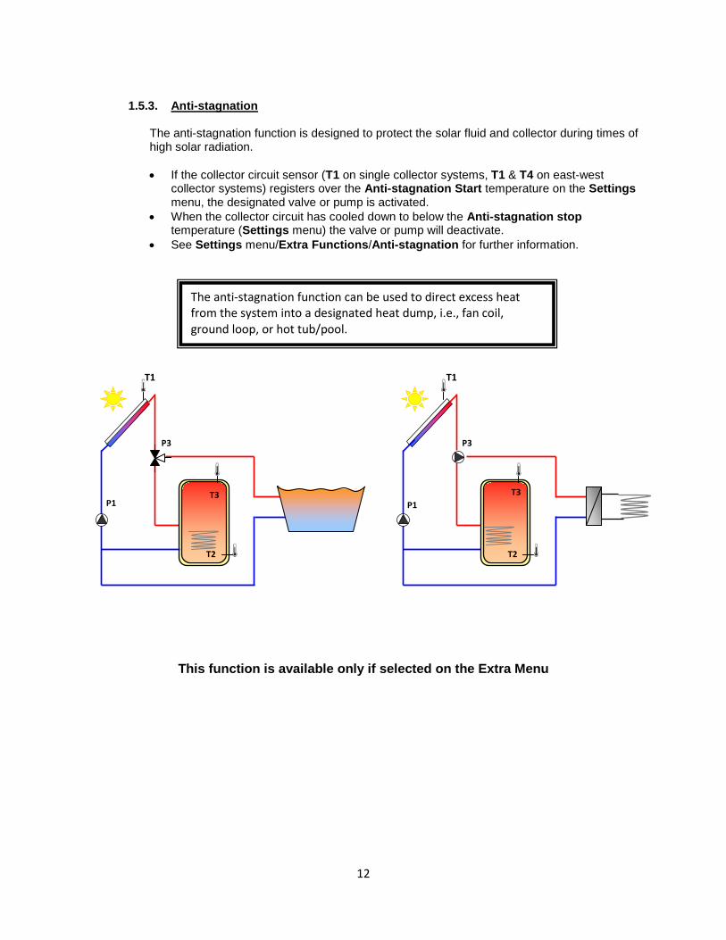
1.5.3. Anti-stagnation
The anti-stagnation function is designed to protect the solar fluid and collector during times of high solar radiation.
• If the collector circuit sensor (T1 on single collector systems, T1 & T4 on east-west
collector systems) registers over the Anti-stagnation Start temperature on the Settings menu, the designated valve or pump is activated.
• When the collector circuit has cooled down to below the Anti-stagnation stop temperature (Settings menu) the valve or pump will deactivate.
• See Settings menu/Extra Functions/Anti-stagnation for further information.
This function is available only if selected on the Extra Menu
P1
T2
T1
P3
T3 P1
T2
T1
P3
T3
The anti-stagnation function can be used to direct excess heat from the system into a designated heat dump, i.e., fan coil, ground loop, or hot tub/pool.

13
1.5.4. Diffcontrol Function:
The Diffcontrol function (only available on System 1) may be used to transfer heated water from one storage tank to another independent of the solar collecting function. This extra function allows separate temperature control of both tanks with user-defined temperature settings (see Settings menu).
Example #1 Additional tank w/no auxiliary heat source
Example #2 Additional tank w/auxiliary heat source
This function is available only if selected on the Extra Menu
P3
P1
T2
Diffcontrol Function used to control the pump to warm up a second tank with temperature control on the system tank.
T1
TC = T3 TW = T4
P3
P1
TC = T3
T2
Diffcontrol Function used to control the pump to transfer heated water from an external source to the system tank.
T1
TW = T4
Other heating system with tank. (Fuel, pellets, wood ….)

14
1.6. External Sensor
This option is useful for collectors that require the sensor to be mounted on the piping external to the collector manifold.
• Select External sensor and press (>) to highlight the line. • Now select yes [using the (+) or (-) keys] if the collector sensor is not mounted directly on the
collector (e.g. on the return pipe). This function will energize the collector pump for 30 seconds twice per hour to ensure that the collector fluid temperature is accurately measured and avoid collector short cycling.
1.7. Protection function :
• Once the line is selected, press (>) to enter the submenu.
The Maxtemp setting is used in the following three protection functions which are designed to prevent overtemp in the collectors. If one or more of the protection functions are activated, the system will automatically activate when the collector temperature reaches the Maxtemp threshold regardless of the tank temperature settings.
(Maxtemp is adjustable from 230°F to 302°F with factory default set at 248°F)
For safety, however, the pumps will automatically shut down when the water temperature in the tank reaches 203°F.
Service--------- - --- -- English Time and date US Version yes System Extra off External sensor no-- Protection func.
Service------------------ English System US Version yes Extra off External sensor no Protection func.
Protection func.----------- Collector Max temp 248°F Cooling no Overheat prot. no Freeze prot no
Code listed and approved hot water tempering valves should be installed throughout the system to ensure that water temperatures at the points of use are
within a safe and acceptable range.
• Use (+) or (-) to select the desired protection function.
• Press (>) to select. • Use the (+) or (-) buttons to select yes.

15
1.7.1. Cooling:
This option is for the protection of the collector fluid. It activates the solar pump (P1 or P2) if the temperature on the collector arrays (T1 or T4) exceeds the collector Max temp value even if the set maximum temperature in the tank is exceeded. The circulation stops when temperature has dropped 20°F. (The pumps will be stopped if the water temperature in the tank reaches 203°F).
• When Yes is selected on the Cooling function, the Recooling function becomes
accessible.
1.7.1.1. Recooling
When Recooling is set to YES, the following safeguards are in place: When the water temperature inside the tank is above Maxtemp tank1 (refer to section 2.1) and the collector temperature is 20°F lower than the actual tank temperature (T2), the pumps will activate to cool the tank through the collector array (typically at night). The pumps will run until either • the temperature of the tank drops below the Maxtemp tank1 setting, or, • the temperature difference between the tank and the collector array is less than 4°F.
1.7.2. Overheat protection (should only be used in conjunction with Cooling function):
When set to YES, this function will stop all collector circulation (P1 and P2) when the collector temperature registers more than 20°F above the collector Maxtemp setting. This function is intended to protect any temperature sensitive system components (Tank, lines, pumps...) in the event of the failure of, for example, tank sensor T2.
1.7.3. Freeze protection:
When set to YES, this option will keep the solar panel temperature (T1 or T4) above the Freeze Protection Temperature setting level (see below) by activating the pump (P1 or P2). • This option could be used to reduce snow accumulation on the panel for increased
efficiency during the day or to avoid potential damage due to freezing.
Note: This function uses energy from the storage tanks and may result in reduced available thermal capacity.
Protection func.----------- Collector Max temp 248°F Cooling yes-----Recooling no Overheat prot. no Freeze prot no
Protection func.------- -- Collector Max temp 248°F Cooling yes Recooling yes Overheat prot. no Freeze prot yes----- Freeze prot temp 38°F
• Adjust the Freeze prot temp setting to the desired temperature.
• (Adjustable from -4°F to + 45°F with factory default of 37°F)

16
1.8. Sensor Options:
The sensors are used for energy measurement and system monitoring. Both flow and pressure sensors can be used.
1.8.1. Impulse Flow Meter
The flow can be measured using a mechanical flow meter (if installed).
• If impulse flow meter is installed (on T6 / PF) select “Yes”, then you must use (+) or (-) to enter the flow meter characteristics in gal / impulse. (Adjustable 0.26 to 6.6 gal/imp with factory value 1.0 gal/imp).
• If no flow meter is installed (factory default setting) you must manually enter the maximum pump flow in gallons/minute using the (+) or (-) buttons. The manufacturer’s specification is generally found in the pump literature or on the manufacturer’s website.
1.8.2. Grundfos Flow Sensor (GDS1)
The controller has 2 dedicated inputs for analog GRUNDFOS sensors (Type VFS Flow sensor or VPS pressure sensor). • The Flow sensor is used for energy measurement and monitoring • The Pressure sensor is used only to monitor the pressure on the primary circuit.
GDS1 may be connected to either a flow or pressure sensor.
Sensor options- - --- -- Impulse meter no - Gallons / impulse 2.6 GDS1 NC GDS2 NC
Sensor options- - --- -- Impulse meter no - Flow (gal/min) 2.6 GDS1 NC GDS2 NC
Sensor options- - --- -- Impulse meter no Flow (gal/min) 2.6 GDS1 VFS 1 – 12 l/min - GDS2 NC

17
Four different GF Flowsensor models are supported by GDS1:
VFS1 - 12 l/min (3.2 gal/min) Flow sensor VFS 2 - 40 l/min (10.6 gal/min) Flow sensor
VFS 5 - 100 l/min (26.4 gal/min) Flow sensor VFS 10- 200 l/min (52.8 gal/min) Flow sensor
Three different GF Pressures sensor models are supported by GDS1:
VPS 0 – 4 bar (58 psi) Pressure sensor VPS 0 – 6 bar (87 psi) Pressure sensor VPS 0 – 10 bar (145 psi) Pressure sensor
To change the sensor type, press (>) then select either your choice or NC (Not Connected) with the (+) or (-) buttons. You can also check the operation of the sensor on the submenu 3.2 Manual testing.
1.8.3. Grundfos Flow Sensor (GDS2)
This input is reserved for connection of a Pressure sensor to monitor the primary circuit.
Three GF Pressure sensors are supported on the GDS2 port:
VPS 0 – 4 bar (58 psi) Pressure sensor VPS 0 – 6 bar (87 psi) Pressure sensor VPS 0 – 10 bar (145 psi) Pressure sensor
To change the sensor type, press (>) then select either your choice or NC (Not Connected) with the (+) or (-) buttons. You can also check the operation of the sensor on the submenu 3.2 Manual testing.
See the controller schematic for more information on the electrical connection.
See the controller schematic for more information on the electrical connection.
Sensor options- - --- -- Impulse meter no Flow (gal/min) 2.6 GDS1 VFS 1 – 12 l/min GDS2 VPS 0 – 4 bar -
18
T1_ _ _°F T2_ _ _°F
P1_ _ _ %
_ _ _ kBTU/h _ _ _ kBTU
T1
T2
SD
1.8.4. Flow Monitoring
System flow is monitored whether or not a flow meter is installed. If no flow meter is installed • the difference between collector temperature and tank temperature is used as indication
of an error in the flow. • A difference of greater than 140°F for more than 30 minutes is interpreted as an error. • When a flow meter is installed • If no flow has been measured for ten minutes after the pump engages, an error is
indicated. When an error is detected, an error message is shown in the display.
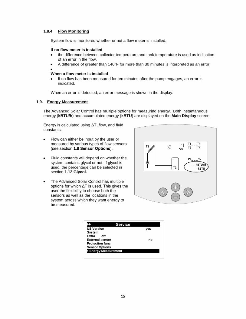
1.9. Energy Measurement
The Advanced Solar Control has multiple options for measuring energy. Both instantaneous energy (kBTU/h) and accumulated energy (kBTU) are displayed on the Main Display screen.
Energy is calculated using ΔT, flow, and fluid constants: • Flow can either be input by the user or
measured by various types of flow sensors (see section 1.8 Sensor Options).
• Fluid constants will depend on whether the system contains glycol or not. If glycol is used, the percentage can be selected in section 1.12 Glycol.
• The Advanced Solar Control has multiple
options for which ΔT is used. This gives the user the flexibility to choose both the sensors as well as the locations in the system across which they want energy to be measured.
Service--------- - --- US Version yes System Extra off External sensor no Protection func. Sensor Options Energy Measurement

19
1.9.1. Warm Sensor
Options for which sensor should be used to measure the higher temperature include the following:
Auto: the control will use the default sensors according to the system chosen (T1 or T1
and T4) T3 (if not being used by an Extra system) T5 GDS1 temp
1.9.2. Cold Sensor
Options for which sensor should be used to measure the colder temperature include the following:
Auto: the control will use the default sensors according to the system chosen (T2 or T2
and T4) T5 GDS1 temp
1.9.3. Flow
Options for which sensor should be used to measure the flow include the following:
Auto: the control will use the Max. Flow entered in section 1.8 Impulse Meter GDS1
Energy Measurement-- - - Temperatures Warm sensor Auto
Cold sensor Auto Flow Auto

20
1.10. Pump P1
This function allows you to choose the type of the pump control used on the output P1. To change the pump type, press (>) then select your choice with the (+) or (-) buttons.
There are 3 choices: No SC - For standard pump without speed control. Phase SC (PhAC SC on Display) - For standard pump with speed control.
- The speed regulation is done by TRIAC (phase control). - Check the following before changing the setting:
• Whether or not your pump will work with this type of speed regulation, • The minimum speed rating of the pump, and, • The speed selector on your pump must be put on the maximum position. • See Section 2.8 Min rev pump for further applicable settings and information.
PWM SC - For PWM pump with speed control. - The speed regulation is done by PWM control.
• Available with GRUNDFOS SOLAR PM type.
Note: If you have selected PWM SC on the Pump P1 or Pump P2, the pump speed will begin to decrease when the dT value is under the dTMax setting for the appropriate tank. At the applicable dTmin setting, the pump will shut off.
1.11. Pump P2
This function allows you to choose the type of the pump used on the output P2. To change the pump type, press (>) then select your choice with the (+) or (-) buttons.
Pump P2 settings are the same as described in the previous section for Pump P1 (No SC, Phase SC, PWM SC).
Service---------- - - System Extra off External Sensor no Protection Function Sensor Options Energy Measurement Pump P1 No SC
Speed of pumps
dTMin
dTMax
100%
0%
dTRange / 2
Speed range / 2
Service---------- - - Extra off External Sensor no Protection Function Sensor Options Energy Measurement Pump P1 PhAC SC Pump P2 No SC C

21
Service---------- - -Sensor Options Energy Measurement Pump P1 PhAC SC Pump P2 No SC Glycol DowFrost HD Glycol Mix 50% Factory setting no % C
In addition, Pump P2 offers a Boost setting for use with a booster pump, commonly used in drainback systems. This setting should be used when a second pump is installed in series on the primary circuit to assist Pump P1 at system start-up. The run time for the booster pump is set when the Boost operation is selected on the Service menu (Boost 1 min, Boost 2 min, etc.).
Important Note: Boost is only available for System 1 (see 1.4.1 System 1)
1.12. Glycol
This submenu allows you to select either NO or DowFrost HD according to your system setup.
1.13. Glycol Mix
• If you have chosen to use a propylene glycol solution in your system, you must specify the concentration on this submenu.
• To set the concentration, press (>) then select a percentage between 0 and 50% (in 10% increments) with the (+) or (-) buttons
1.14. Reset to Factory default settings:
• Press (>) to highlight this line if you want to
reset all settings to their factory default.
• Select “yes” with (+) key.
• Press (<) repeatedly to return to the main
Service---------- - - External Sensor no Protection Function Sensor Options Energy Measurement Pump P1 PhAC SC Pump P2 No SC Glycol No C
Service---------- - - Protection Function Sensor Options Energy Measurement Pump P1 PhAC SC Pump P2 No SC Glycol DowFrost HD Glycol Mix 50% % C
IMPORTANT NOTE: The factory default setting on the Operation Menu is OFF. This prevents system components (P1, P2, P3) from operating until system is set up. To turn on the system, change the setting to AUTOMATIC (Active). See Operation menu / 3.1 for further info.
22
Service---------- - -Energy Measurement Pump P1 PhAC SC Pump P2 No SC Glycol DowFrost HD Glycol Mix 50% Factory setting no Reset op time no % C
Service---------- - - Pump P1 PhAC SC Pump P2 No SC Glycol DowFrost HD Glycol Mix 50% Factory setting no Reset op time no Time graf temp 5m m C
Service---------- - - Pump P2 No SC Glycol DowFrost HD Glycol Mix 50% Factory setting no Reset op time no Time graf temp 5m Time graf op 1h m C
Service---------- - - Glycol DowFrost HD Glycol Mix 50% Factory setting no Reset op time no Time graf temp 5m Time graf op 1h Calib sensors m C
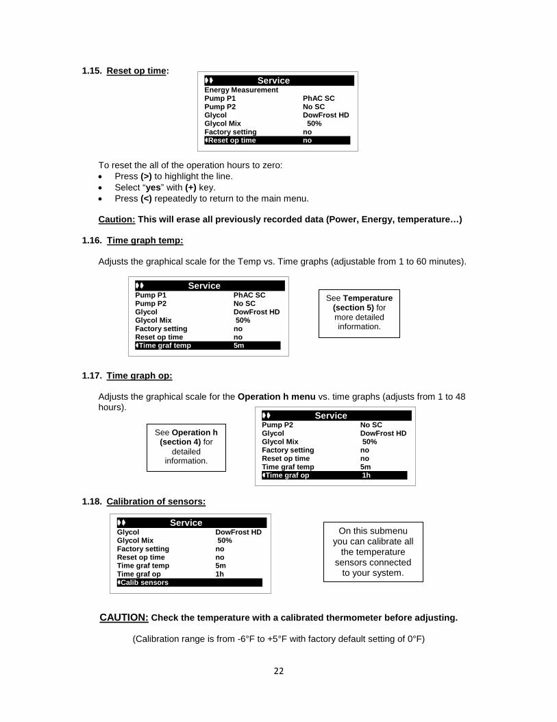
1.15. Reset op time:
To reset the all of the operation hours to zero: • Press (>) to highlight the line. • Select “yes” with (+) key. • Press (<) repeatedly to return to the main menu. Caution: This will erase all previously recorded data (Power, Energy, temperature…)
1.16. Time graph temp:
Adjusts the graphical scale for the Temp vs. Time graphs (adjustable from 1 to 60 minutes).
1.17. Time graph op:
Adjusts the graphical scale for the Operation h menu vs. time graphs (adjusts from 1 to 48 hours).
1.18. Calibration of sensors:
CAUTION: Check the temperature with a calibrated thermometer before adjusting.
(Calibration range is from -6°F to +5°F with factory default setting of 0°F)
See Temperature (section 5) for more detailed information.
See Operation h (section 4) for
detailed information.
On this submenu you can calibrate all
the temperature sensors connected
to your system.
23
Service---------- - - External Sensor no Protection Function Sensor Options Energy Measurement Pump P1 PhAC SC Pump P2 No SC Prio 1 1
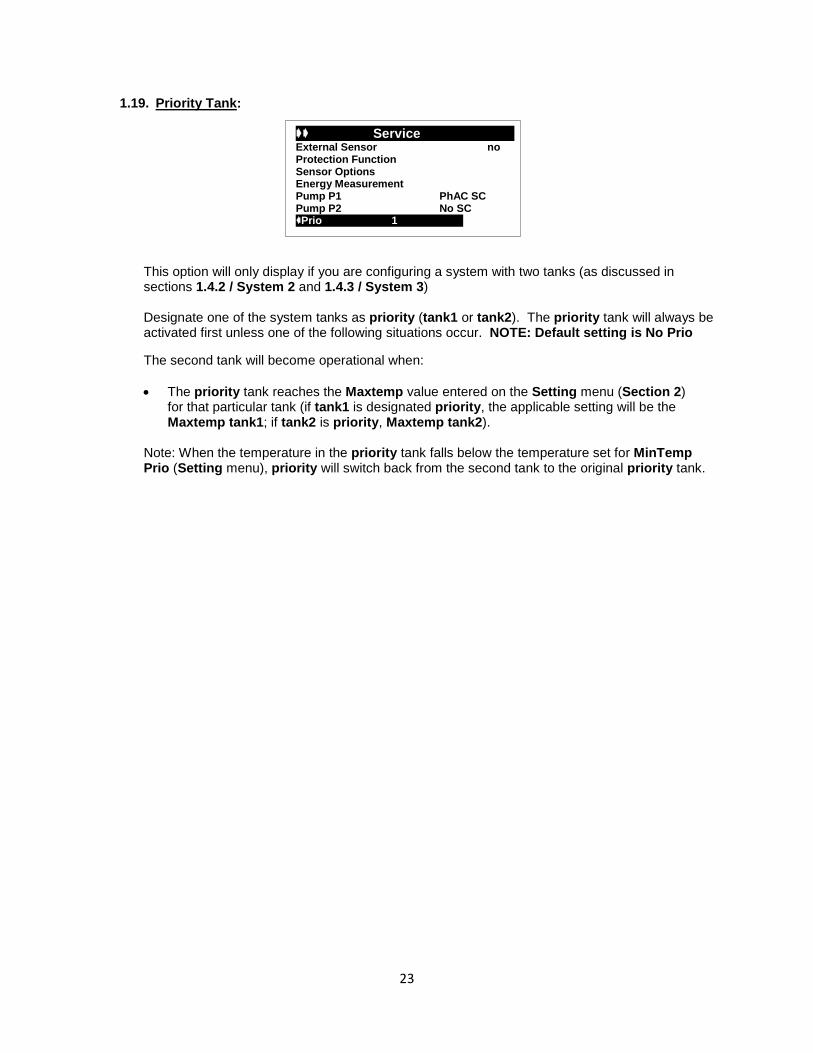
1.19. Priority Tank:
This option will only display if you are configuring a system with two tanks (as discussed in sections 1.4.2 / System 2 and 1.4.3 / System 3) Designate one of the system tanks as priority (tank1 or tank2). The priority tank will always be activated first unless one of the following situations occur. NOTE: Default setting is No Prio
The second tank will become operational when: • The priority tank reaches the Maxtemp value entered on the Setting menu (Section 2)
for that particular tank (if tank1 is designated priority, the applicable setting will be the Maxtemp tank1; if tank2 is priority, Maxtemp tank2).
Note: When the temperature in the priority tank falls below the temperature set for MinTemp Prio (Setting menu), priority will switch back from the second tank to the original priority tank.

24
Settings ------------- Maxtemp tank1 149°F dT Max tank1 49°F dT Min tank1 38°F Maxtemp tank2 149°F dT Max tank2 49°F dT Min tank2 38°F Mintemp prio tank 32°F
2. Setting Menu:
This menu allows you to set all adjustable parameters of your system. Not all options are available with all systems.
2.1. Maxtemp tank1: Maximum value of desired water temperature in tank1 during normal operation.
(Adjustable from 59°F to 203°F with factory default set at 149°F)
2.2. dTMax tank1: Difference (ΔT) between collector temperature (T1) and tank1 temperature (T2) that will automatically engage pump1.
(Adjustable from 7°F to 72°F with factory default set at 12°F)
2.3. dTMin tank1: Difference (ΔT) between collector temperature (T1) and Tank1 temperature (T2) that will automatically disengage pump1.
(Adjustable from 4°F to 63°F with factory default set at 5°F) NOTE: dTMin will always be 3-7°F less than dTMax
2.4. Maxtemp tank2: Only applicable on systems with two tanks (as discussed in sections 1.4.2 /
System 2 and 1.4.3 / System 3). Sets the maximum value of desired water temperature on the tank2.
(Adjustable from 59°F to 203°F with factory default set at 149°F)
2.5. dTMax tank2: Only applicable on systems with two tanks (as discussed in sections 1.4.2 / System 2 and 1.4.3 / System 3).
Difference (ΔT) between collector temperature (T1) and tank2 temperature (T4) that will automatically engage pump1 with system2 or pump2 with system3.
(Adjustable 7°F to 72°F with factory default set at 12°F)
2.6. dTMin tank2: Only applicable on systems with two tanks (as discussed in sections 1.4.2 / System 2 and 1.4.3 / System 3).
Difference (ΔT) between collector temperature (T1) and tank2 temperature (T4) that will automatically disengage pump1 with system2 or pump2 with system3.
(Adjustable from 3°F to 63°F) with factory default set at 5°F)
NOTE: dTMin tank2 will always be 3-7°F less than dTMax tank2
Tank1 T2 (°F)
dTMin
dTMax
P1
Collector T1 (°F)
Maxtemp Tank1
dTMax
dT = T1 – T2
100%
0%
dTMax
Pump speed regulation
Note: If the installed system has two tanks, the adjacent graph is also valid when using the sensor information from the second tank.

25
2.7. Mintemp prio tank:
This will only display on systems configured with two tanks (as discussed in sections 1.4.2 / System 2 and 1.4.3 / System 3)
This option allows the user to define the minimum temperature setting for the priority tank (as designated in the process described in the Service menu / 1.19 Priority Tank). When the temperature in the priority tank falls below this setting, the system will switch back from the second tank (temporarily deemed priority due to overheating in the main tank) to the original priority tank.
(Adjustable from 32°F to the MaxTemp tank setting for the priority tank with factory default set at 32°F)
2.8. Min rev pump:
This option will only display if Phase Speed Control (Phase SC) is selected on the Service menu 1.10 Pump P1 or 1.11 Pump P2.
• Highlight Min rev pump and press (>) • Use the (+) or (-) buttons to set the minimum speed of the pumps
(Adjustable from 30% to 100% with factory default set at 50%)
The speed of the pump will start to decrease when the dT value is under the dTMax setting for the appropriate tank; the Min rev pump setting will come into effect at the applicable dTmin setting.
Settings --------------- Maxtemp tank1 149°F dT Max tank1 49°F dT Min tank1 38°F Maxtemp tank2 149°F dT Max tank2 49°F dT Min tank2 38°F Min temp prio tank 85°F
Settings --------------- Maxtemp tank1 149°F dT Max tank1 49°F dT Min tank1 38°F Maxtemp tank2 149°F dT Max tank2 49°F dT Min tank2 38°F Min rev pump 100%
WARNING: Setting Min rev pump below 50% may prevent pump operation under various conditions (e.g. high head pressure due to system design or cold/degraded glycol solution).
Speed of pumps
dTMin
dTMax
100%
Min rev pump value
dTRange / 2
Speed range / 2

26
2.9. dTMax return Available for System 6 only Temperature (ΔT T3/T4) that engages the valve and opens the boiler circuit to energy from the solar circuit.
2.10. dT Min return Available for System 6 only Temperature (ΔT T3/T4) that closes the valve to the solar circuit and re-routes circulation through the boiler circuit only.
2.11. dTFs: Full speed
Temperature (ΔT T1/T2) at which the pump speed will be 100% - allows much finer ΔT control.
2.12. Mintemp Collector:
This option allows you to set the minimum collector temperature required for solar loading. (Adjustable from 32°F to 210°F with factory default set at 32°F)
2.13. Delay P2 Available for System 7 only
User defined setting that dictates the length of time after the activation of P1 before P2 engages.
(Adjustable from 0 – 30 minutes with the default set at 3 minutes.)
Settings -------------- Maxtemp tank1 149°F dT Max tank1 49°F dT Min tank1 38°F dT Max return 12°F dT Min return 5°F Min rev pump 50% dTFS 50°F
Settings -------------- dT Max tank1 49°F dT Min tank1 38°F dTMax return 12°F dTMin return 5°F Min rev pump 50% dTFS 59°F Mintemp coll. 32°F
Settings -------------- Maxtemp tank1 149°F dT Max tank1 49°F dT Min tank1 38°F Min rev pump 50% dTFS 59°F Mintemp coll. 32°F Delay P2 3min
27
EXTRA FUNCTIONS
The following three options are only available if you have made the corresponding selection on the Service / Extra menu discussed in Section 1.5.
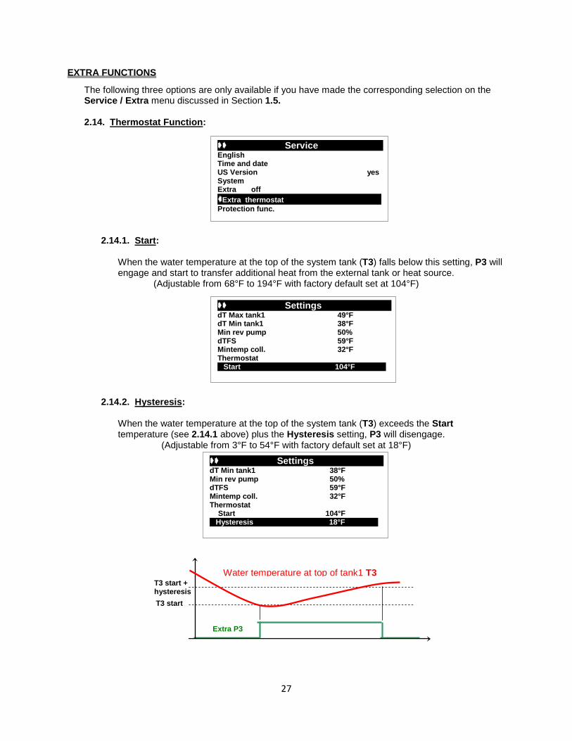
2.14. Thermostat Function:
2.14.1. Start:
When the water temperature at the top of the system tank (T3) falls below this setting, P3 will engage and start to transfer additional heat from the external tank or heat source.
(Adjustable from 68°F to 194°F with factory default set at 104°F)
2.14.2. Hysteresis:
When the water temperature at the top of the system tank (T3) exceeds the Start temperature (see 2.14.1 above) plus the Hysteresis setting, P3 will disengage.
(Adjustable from 3°F to 54°F with factory default set at 18°F)
Service--------- - --- -- English Time and date US Version yes System Extra off Extra thermostat -- Protection func.
Settings -------------- dT Max tank1 49°F dT Min tank1 38°F Min rev pump 50% dTFS 59°F Mintemp coll. 32°F Thermostat Start 104°F
Settings -------------- dT Min tank1 38°F Min rev pump 50% dTFS 59°F Mintemp coll. 32°F Thermostat Start 104°F Hysteresis 18°F
Water temperature at top of tank1 T3
T3 start
T3 start + hysteresis
Extra P3
28
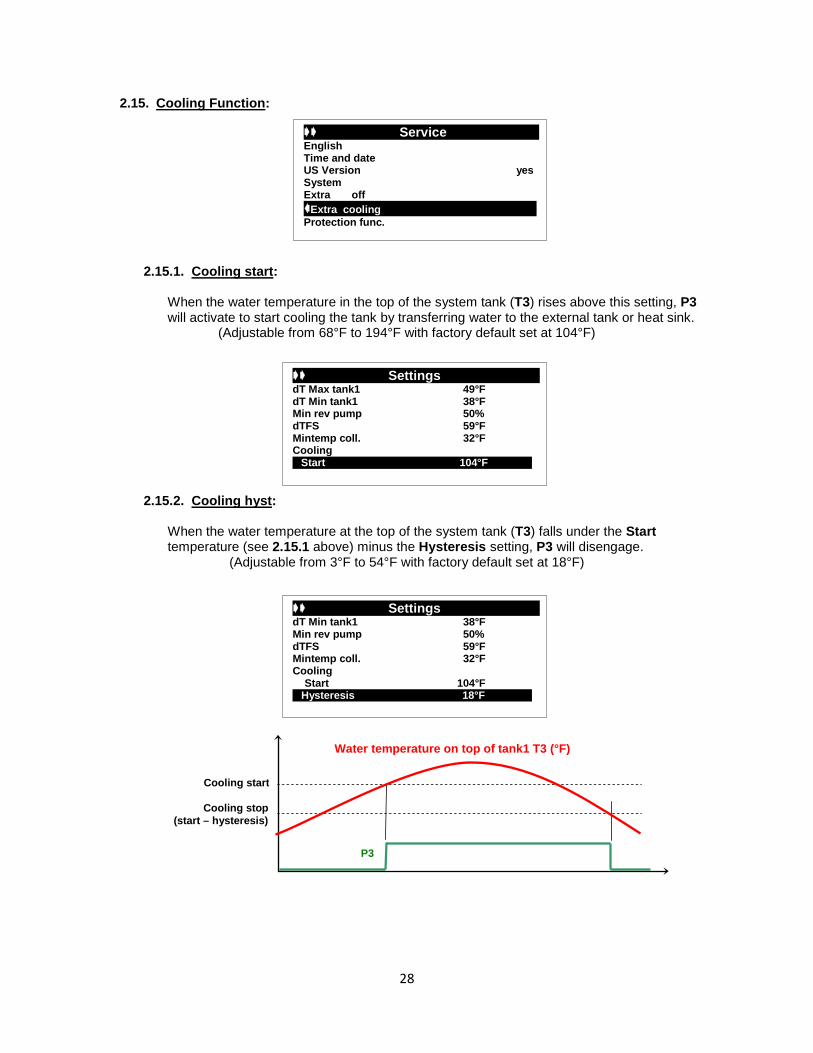
2.15. Cooling Function:
2.15.1. Cooling start:
When the water temperature in the top of the system tank (T3) rises above this setting, P3 will activate to start cooling the tank by transferring water to the external tank or heat sink.
(Adjustable from 68°F to 194°F with factory default set at 104°F)
2.15.2. Cooling hyst:
When the water temperature at the top of the system tank (T3) falls under the Start temperature (see 2.15.1 above) minus the Hysteresis setting, P3 will disengage.
(Adjustable from 3°F to 54°F with factory default set at 18°F)
Service--------- - --- -- English Time and date US Version yes System Extra off Extra cooling -- Protection func.
Settings -------------- dT Max tank1 49°F dT Min tank1 38°F Min rev pump 50% dTFS 59°F Mintemp coll. 32°F Cooling Start 104°F
Settings -------------- dT Min tank1 38°F Min rev pump 50% dTFS 59°F Mintemp coll. 32°F Cooling Start 104°F Hysteresis 18°F
Water temperature on top of tank1 T3 (°F)
Cooling stop (start – hysteresis)
Cooling start
P3

29
Settings -------------- dT Max tank1 49°F dT Min tank1 38°F Min rev pump 50% dTFS 59°F Mintemp coll. 32°F Antistagnation Start 230°F
2.16. Anti-stagnation
2.16.1. Start
When the temperature of the fluid in the collector rises above this setting, the designated valve or pump is activated.
(Adjustable from 32°F to 392°F with factory default set at 230°F)
2.16.2. Stop
When the temperature of the fluid in the collector falls below this setting, the designated valve or pump disengages.
(Adjustable from 32°F to 302°F with factory default set at 200°F)
2.16.3. Output option
This feature allows you to choose to use either P1/P3 (both) or P3 (only) to circulate the fluid.
Service--------- - --- -- English Time and date US Version yes System Extra off Extra antistagnation -- Protection func.
Settings -------------- dT Min tank1 38°F Min rev pump 50% dTFS 59°F Mintemp coll. 32°F Antistagnation Start 230°F Stop 194°F
Settings -------------- Min rev pump 50% dTFS 59°F Mintemp coll. 32°F Antistagnation Start 230°F Stop 194°F Output option P1/P3

30
2.17. Diffcontrol Function:
For systems with an additional tank but without an auxiliary heat source (Service/1.5.4 Example #1)
2.17.1. Max cold tank:
When the temperature at the top of the external tank (T3) registers above this setting, P3 will shutoff and the exchange of heat will stop (T3 = TC).
(Adjustable from 59°F to 203°F with factory default set at 149°F)
2.17.2. Min warm tank:
The temperature at the top of the system tank (T4) must register above this setting before P3 will engage and the exchange of heat will start (T4 = TW).
(Adjustable from 32°F to 203°F° with factory default set at 59°F)
For systems with an additional tank AND an auxiliary heat source (Service / 1.5.4 Example #2)
2.17.3. Max cold tank:
When the temperature at the top of the system tank (T3) registers above this setting, P3 will shutoff and the exchange of heat will stop (T3 = TC).
(Adjustable from 59°F to 203°F with factory default set at 149°F)
2.17.4. Min warm tank:
The temperature at the top of the external tank (T4) must register above this setting before P3 will engage and the exchange of heat will start (T4 = TW).
(Adjustable from 32°F to 203°F° with factory default set at 59°F)
2.17.5. dTMax:
Temperature difference (ΔT) between the tank designated as cold storage (TC) and the one designated as warm storage (TW) at which P3 will automatically start the exchange.
(Adjustable from 5°F to 72°F with factory default set at 18°F) 2.17.6. dTMin:
Temperature difference (ΔT) between TC and TW at which P3 will automatically stop the exchange.
(Adjustable from 3°F to 54°F with factory default set at 9°F)
Service--------- - --- -- English Time and date US Version yes System Extra off Extra diffcontrol -- Protection func.
Warm storage TW Cold storage TC
MinWarm tank
MaxCold Tank
Extra P3
dTMin dTMax
31
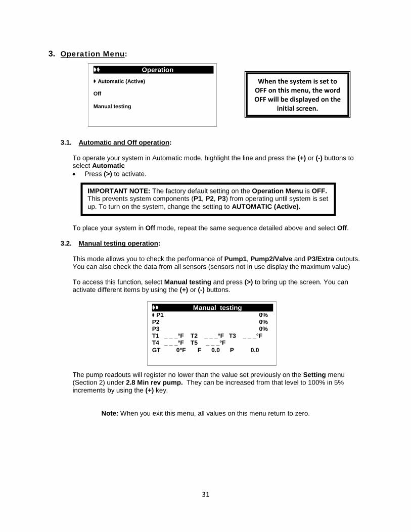
3. Operation Menu: 3.1. Automatic and Off operation:
To operate your system in Automatic mode, highlight the line and press the (+) or (-) buttons to select Automatic • Press (>) to activate.
To place your system in Off mode, repeat the same sequence detailed above and select Off.
3.2. Manual testing operation:
This mode allows you to check the performance of Pump1, Pump2/Valve and P3/Extra outputs. You can also check the data from all sensors (sensors not in use display the maximum value)
To access this function, select Manual testing and press (>) to bring up the screen. You can activate different items by using the (+) or (-) buttons.
The pump readouts will register no lower than the value set previously on the Setting menu (Section 2) under 2.8 Min rev pump. They can be increased from that level to 100% in 5% increments by using the (+) key.
Note: When you exit this menu, all values on this menu return to zero.
Operation ------------ Automatic (Active) Off
Manual testing
IMPORTANT NOTE: The factory default setting on the Operation Menu is OFF. This prevents system components (P1, P2, P3) from operating until system is set up. To turn on the system, change the setting to AUTOMATIC (Active).
Manual testing P1 0% P2 0% P3 0% T1 _ _ _°F T2 _ _ _°F T3 _ _ _°F T4 _ _ _°F T5 _ _ _°F GT 0°F F 0.0 P 0.0
When the system is set to OFF on this menu, the word OFF will be displayed on the
initial screen.

32
4. Operation h Menu: This menu offers both a data view and a graph view for the Operation, dT, Power and Energy values. You can change the scale of these graphs on the Service menu under Time graf op. Using the (+) or (-) buttons, select Time graph op and press (>) to highlight the line. • Now you can change the scale with the (+) or (-) buttons.
(Adjustable from 1 to 48 hours with factory default set at1 hour)
Press (<) repeatedly to return to the main menu.
Operation h------------------ Operation _ _ h dT _ _°F Power _ _kBTU/h Energy _ _kBTU Volume _ _Gallons SD card Off
Service--------- - --- -- Pump P1 PhAC SC Pump P2 No SC Glycol no Factory setting no Reset op time no Time graf temp 5m Time graf op 1h --
NOTE: WHEN VIEWING GRAPHS ON THE CONTROL DISPLAY, the most current data always displays on the left side of the graph; historical data scrolls to the right.
- + 0d 00h
Operation 0.0h
Current Data

33
4.1. SD Card Option
You can use the included SD Card to store data and transfer system settings from your PC to the Solar Control. The Dataviewer software that is installed on the SD Card also allows you to view system performance information in graph form. Information on the SD Card is limited to either settings that you write to it from your PC or system data that is recorded while the SD Card is inserted into the Control (see below).
4.1.1. Initializing the SD Card
It is important to follow these steps as they are listed. Once initialized, the SD Card can be used to set up multiple controls.
• Insert the SD Card into the Control • When you click on (>) to select the SD Card line of the
Operation h menu, The display will change to ON. • Click on (>) again, changing the display to OFF. Wait until
the display automatically returns to the initial screen before proceeding to the next step.
• Press gently on the end of the card & it will pop out for easy removal.
• Insert the SD Card into the Control again. • This time, a screen will pop-up and ask if you want
to “Update settings from SD Card?” • Click on “NO” – you haven’t configured them yet.
(There is no way to manually write or save settings from the Control to the SD Card.)
• Click on (<) to leave that sub-menu; the SD Card status display is ON.
• Click on (>) again, changing the display to OFF. Again, wait until the display automatically returns to the initial screen before proceeding to the next step.
• Press gently on the end of the card & it will pop out for easy removal.
NOTE: This procedure will only need to be done once per SD Card.
Operation h----- ---- Operation _ _ h dT _ _°F Power _ _kBTU/h Energy _ _kBTU Volume _ _gal. SD card OFF
Card is not in use
Card is in use
Operation h----- ---- Operation _ _ h dT _ _°F Power _ _kBTU/h Energy _ _kBTU Volume _ _gal. SD card ON

34
4.1.2. Configuring/Changing your system settings
• After initializing and removing the SD Card from the Solar Control, insert it into the included USB SD Card Reader.
• Make sure that the SD Card is securely seated in the slot. If the card is not properly seated, your
computer will not recognize the Reader. If this occurs, check to make sure that the SD
Card is solidly installed – the SD Card will fit into the Reader if it is turned backwards, but it will not fit far enough in to connect to the card reader.
• Insert the USB SD Card Reader into an available USB Port on your PC.
• With the SD Card inserted into your PC, you can configure all of the Solar Control settings on a single screen
4.1.3. Using the DataViewer software
The DataViewer software is supplied on the USB SD Card Reader. • When you insert the Reader/Adapter into a USB port on your computer, you will see a
screen asking what you want Windows to do. Highlight “Open folder to view the files using Windows Explorer” and click “OK”.
• Double click on
• The Charts tab (first to appear) will be blank until you have left the card installed in the control long enough for system data to accumulate on it.
Click on the Settings tab In this window you can view and customize the configuration of your system. Click on the “Write” button to save your new settings to the SD Card.
35
4.1.4. Transferring Data from the PC to the Control
• Remove the SD Card from your PC and insert it (after removing it from the
Reader/Adapter) into the slot on the side of the Control. • When the screen pops-up and asks if you want to “Update settings from SD Card?”
Click on (>), changing the display to YES. This will change the control settings to the configuration you set up on your PC.
• You can now either remove the SD Card (after first making sure that it is turned off on the main Operation h menu) or turn the SD Card on and leave it in the control to gather system performance data as described in the next section.
Do not remove the SD Card without first deactivating it on the Operation h menu.
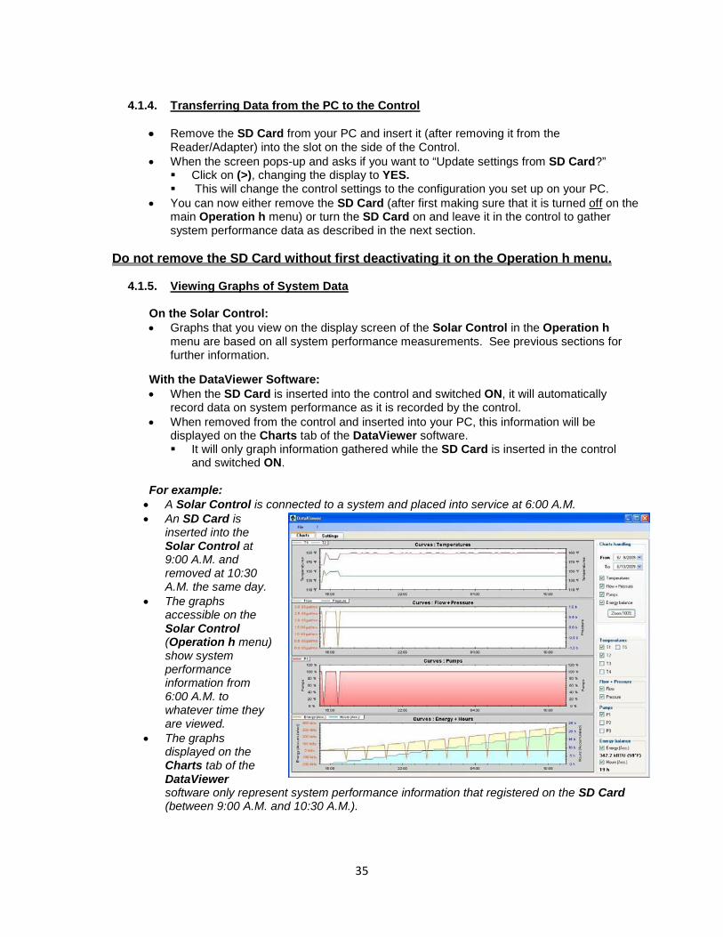
4.1.5. Viewing Graphs of System Data
On the Solar Control: • Graphs that you view on the display screen of the Solar Control in the Operation h
menu are based on all system performance measurements. See previous sections for further information.
With the DataViewer Software: • When the SD Card is inserted into the control and switched ON, it will automatically
record data on system performance as it is recorded by the control. • When removed from the control and inserted into your PC, this information will be
displayed on the Charts tab of the DataViewer software. It will only graph information gathered while the SD Card is inserted in the control
and switched ON.
For example: • A Solar Control is connected to a system and placed into service at 6:00 A.M. • An SD Card is
inserted into the Solar Control at 9:00 A.M. and removed at 10:30 A.M. the same day.
• The graphs accessible on the Solar Control (Operation h menu) show system performance information from 6:00 A.M. to whatever time they are viewed.
• The graphs displayed on the Charts tab of the DataViewer software only represent system performance information that registered on the SD Card (between 9:00 A.M. and 10:30 A.M.).

36
4.1.6. Backup Choosing this feature on the File menu protects settings and data by saving a copy of the DataViewer program and accumulated information to a location specified by the user. If the system SD Card becomes damaged, the information from the Backup file can be loaded onto a new card.
4.1.7. Exporting to Excel With the DataViewer software you have the ability to export the system performance information to Excel for further analysis. • On the Files menu in DataViewer, select
Excel Export. DataViewer will export the file (in .csv format) to a location that you select.
• In Excel, click Open on the File menu. (You may have to change the “Files of type” to All Files to find the exported file.)
• Select Column A in the open file. • From the Data menu, click on Text to
Columns • Select Delimited (then click Next) • Select semicolon (click Next) • In the Column/Data format you can either leave it as General, or select a different format
for the entries in each column. Most commonly, Column A would be changed to Date. • Click Finish
4.1.8. Send by Outlook Express & Export all Zip
These two options on the File menu are extremely useful as troubleshooting tools. Those that use Outlook Express can use the Send by Outlook Express feature to transmit the data and configuration files to another party for remote assistance and/or diagnosis of a problem. Selecting Export all Zip creates a .zip file of that same information that can be attached to any email.
4.1.9. Settings File: Save & Settings File: Load
The DataViewer software allows the user to design and save more than one system configuration on a single SD Card. • After configuring a system using the DataViewer software, save the settings to the
current directory on the SD Card by clicking on the Write button at the top of the Settings screen.
• Save the configuration by choosing Settings File: Save on the drop-down File menu. The file will be saved as an .svg file in the SVG folder.
• Configure another system set-up and repeat the above process. • To access any of the saved files, choose Settings File: Load from the File menu. This
action will display the saved settings as the current (or active) configuration.

37
5. Temperatures Menu:
This menu displays the temperatures of all connected sensors except T5 (see 1.9 Energy Measurement). Using the (+) or (-) buttons you can select a particular sensor and see its time graph by pressing (>).
You can change the scale of these graphs on the Service menu under Time graph temp.
Using the (+) or (-) buttons, select Time graph temp and press (>) to highlight the line. • Now you can change the scale with the (+) or (-) buttons.
(Adjustable from 1 to 60 minutes with factory default of 5 minutes)
Press (<) repeatedly to return to the main menu.
Temperatures---- -- T1 – Collector1 _ _ _°F T2 – Collector2 _ _ _°F Tank1 bottom _ _ _°F Tank top _ _ _°F
82 50 18
0:00 - +
Collector1 __°F
Service--------- - --- -- Energy Measurement Pump P1 PhAC SC Pump P2 No SC Glycol no Factory setting no Reset op time no Time graf temp 5m --

38
6. Special Functions:
6.1. Pump exercise function:
If pumps are not activated for a period of 48 hours, this function will automatically activate them for 15 seconds to avoid jams.
6.2. Dimmer function:
To save power, the backlight automatically dims if there is no keypad activity for a period of 10 minutes.
After automatically dimming, the first push on any keypad key will activate the backlight.
6.3. Security function:
To avoid unintentional/unauthorized changes, System type and Extra Function selection (No, Thermostat, Cooling, Anti-stagnation, or Diffcontrol) are inaccessible after the control has been connected to an electrical source and there are no keystrokes for a period of 4 hours. If you want to modify these parameters at any time past the 4 hour settings lock, you must disconnect and reconnect the power to the controller. • This action will not reset the control; it will only allow access to make modifications. To reset all of the control settings to the factory default values, see Services / section 1.14 Reset to factory default settings.
39
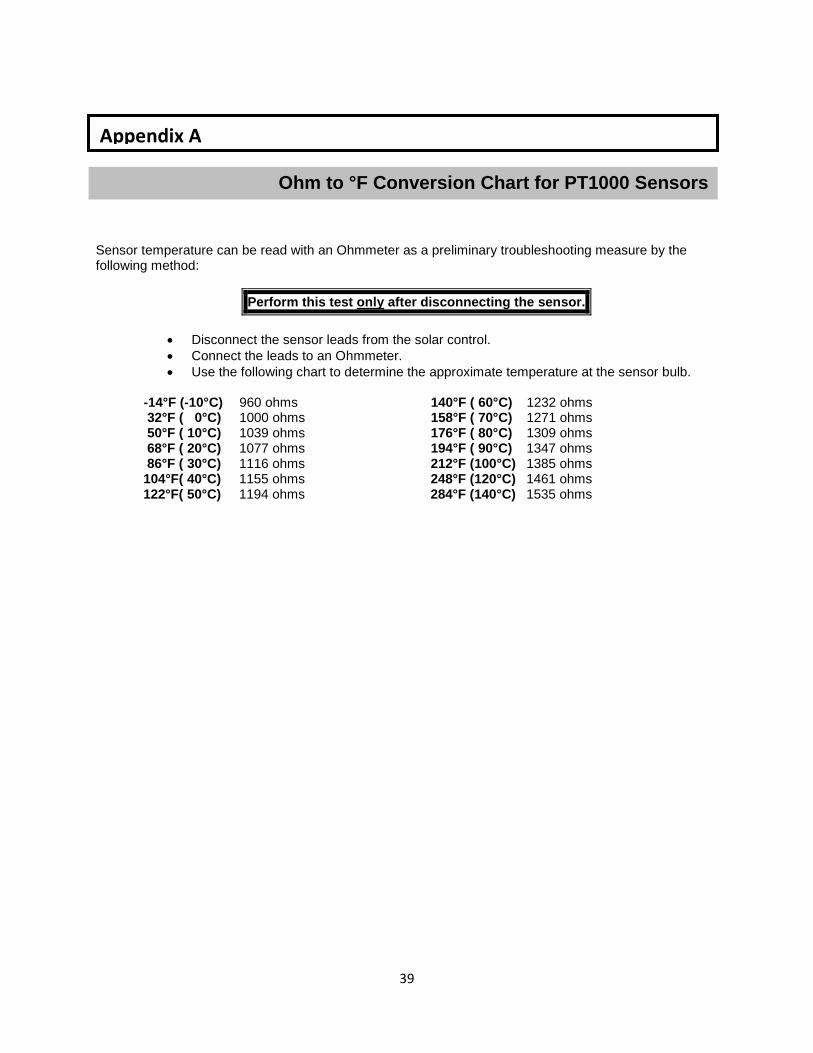
Sensor temperature can be read with an Ohmmeter as a preliminary troubleshooting measure by the following method:
Perform this test only after disconnecting the sensor.
• Disconnect the sensor leads from the solar control. • Connect the leads to an Ohmmeter. • Use the following chart to determine the approximate temperature at the sensor bulb.
-14°F (-10°C) 960 ohms 140°F ( 60°C) 1232 ohms 32°F ( 0°C) 1000 ohms 158°F ( 70°C) 1271 ohms 50°F ( 10°C) 1039 ohms 176°F ( 80°C) 1309 ohms 68°F ( 20°C) 1077 ohms 194°F ( 90°C) 1347 ohms 86°F ( 30°C) 1116 ohms 212°F (100°C) 1385 ohms
104°F( 40°C) 1155 ohms 248°F (120°C) 1461 ohms 122°F( 50°C) 1194 ohms 284°F (140°C) 1535 ohms
Ohm to °F Conversion Chart for PT1000 Sensors
Appendix A
40
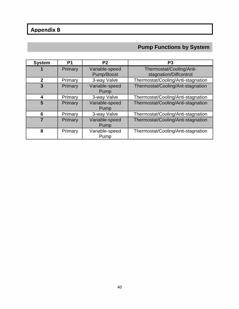
System P1 P2 P3 1 Primary Variable-speed
Pump/Boost Thermostat/Cooling/Anti-
stagnation/Diffcontrol 2 Primary 3-way Valve Thermostat/Cooling/Anti-stagnation 3 Primary Variable-speed
Pump Thermostat/Cooling/Ant-stagnation
4 Primary 3-way Valve Thermostat/Cooling/Anti-stagnation 5 Primary Variable-speed
Pump Thermostat/Cooling/Anti-stagnation
6 Primary 3-way Valve Thermostat/Cooling/Anti-stagnation 7 Primary Variable-speed
Pump Thermostat/Cooling/Anti-stagnation
8 Primary Variable-speed Pump
Thermostat/Cooling/Anti-stagnation
Pump Functions by System
Appendix B

41
Controller Schematic
Appendix C

42
Limited Warranty SolarHOT, Inc. warrants this solar control and its associated sensors (the product) to be free from defects in material and workmanship for a period of one (1) year from the date of original purchase. During this period, SolarHOT, Inc. will replace the product or refund the original cost of the product, at SolarHOT’s option, if the product is proven defective under normal usage within the warranty period. This limited warranty does not cover shipping costs, nor does it cover a product subjected to misuse or accidental damage. This warranty does not cover the cost of installation, diagnosis, removal or reinstallation, any labor or other material costs, loss of use, or damage to other property if this product does not work properly. THIS LIMITED WARRANTY IS IN LIEU OF ALL OTHER WARRANTIES AND SOLARHOT, INC. SPECIFICALLY DISCLAIMS ALL OTHER WARRANTIES, EXPRESS OR IMPLIED, INCLUDING THE IMPLIED WARRANTIES OF MERCHANTABILITY AND FITNESS FOR A PARTICULAR PURPOSE. The remedies described above are the sole remedies for breach of warranty. In no event shall SolarHOT, Inc. be liable for any special, consequential or incidental damages arising from use or installation of this product.