
FRENIC Solar Pump Controller - fujielectric.co.in · FRENIC Solar Pump Controller Compatible with...
4
FRENIC Solar Pump Controller Compatible with Induction and PMSM Pumps Frenic Mini Solar Controller Frenic Ace Solar Controller Power Range-0.5 to 15KW Power Range- 18.5 to 90 KW Installation Over 15000 Across India Architecture of Solar Pump System: Solar Panel Pump Controller Submersible Pump Water Tank irrigation • The performance of a solar water pumping system consists of a photovoltaic (PV) array, Motors; it can be Submersible or Surface . The efficiency of the system is improved with Maximum Power Point Tracker (MPPT). • The MPPT (V MPP search) will change the set point value in order to search the maximum power of the photovoltaic panel. The maximum power point depends on the panel temperature and the solar irradiation. • Sudden change in the DC bus voltage, caused by a fast change on the irradiation condition (for example from/to cloudy conditions). The Controller is suitable to follow the actual DC bus voltage by a multiplication factor. FEI/DP/Solar/032/R2
Transcript of FRENIC Solar Pump Controller - fujielectric.co.in · FRENIC Solar Pump Controller Compatible with...

FRENIC Solar Pump ControllerCompatible with Induction and PMSM Pumps
Frenic Mini Solar Controller Frenic Ace Solar ControllerPower Range-0.5 to 15KW Power Range- 18.5 to 90 KW
Installation Over 15000 Across India
Architecture of Solar Pump System:
Solar Panel
Pump Controller
Submersible Pump
Water Tank
irrigation
• Theperformanceofasolarwaterpumpingsystemconsistsofaphotovoltaic(PV)array,Motors;itcanbeSubmersibleorSurface.Theefficiencyofthesystem is improved withMaximum Power PointTracker(MPPT).
• TheMPPT(VMPPsearch)willchangethesetpointvalue in order to search themaximumpower ofthephotovoltaicpanel.Themaximumpowerpointdependson thepanel temperatureand thesolarirradiation.
• Sudden change in the DC bus voltage, causedbya fastchangeon the irradiationcondition (forexamplefrom/tocloudyconditions).TheControllerissuitabletofollowtheactualDCbusvoltagebyamultiplicationfactor.
FEI/DP/Solar/032/R2
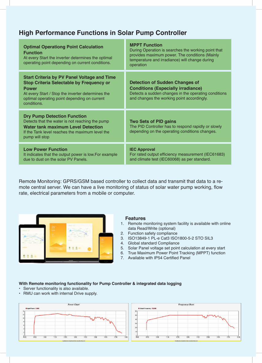
Optimal Operationg Point Calculation FunctionAt every Start the inverter determines the optimal operating point depending on current conditions.
MPPT FunctionDuring Operation is searches the working point that provides maximum power. The conditions (Mainly temperature and irradiance) will change during operation
Start Criteria by PV Panel Voltage and TimeStop Criteria Selectable by Frequency or Power At every Start / Stop the inverter determines the optimal operating point depending on current conditions.
Detection of Sudden Changes of Conditions (Especially irradiance)Detects a sudden changes in the operating conditions and changes the working point accordingly.
Dry Pump Detection FunctionDetects that the water is not reaching the pumpWater tank maximum Level DetectionIf the Tank level reaches the maximum level the pump will stop
Two Sets of PID gainsThe PID Controller has to respond rapidly or slowly depending on the operating conditions changes.
Low Power FunctionIt indicates that the output power is low.For example due to dust on the solar PV Panels.
IEC ApprovalFor rated output efficiency measurement (IEC61683) and climate test (IEC60068) as per standard.
High Performance Functions in Solar Pump Controller
Remote Monitoring: GPRS/GSM based controller to collect data and transmit that data to a re-mote central server. We can have a live monitoring of status of solar water pump working, flow rate, electrical parameters from a mobile or computer.
With Remote monitoring functionality for Pump Controller & integrated data logging • Server functionality is also available.• RMU can work with internal Drive supply.
Features1. Remote monitoring system facility is available with online
data Read/Write (optional) 2. Function safety compliance3. ISO13849-1 PL-e Cat3 ISO1800-5-2 STO SIL34. Global standard Compliance5. Solar Panel voltage set point calculation at every start6. True Maximum Power Point Tracking (MPPT) function7. Available with IP54 Certified Panel
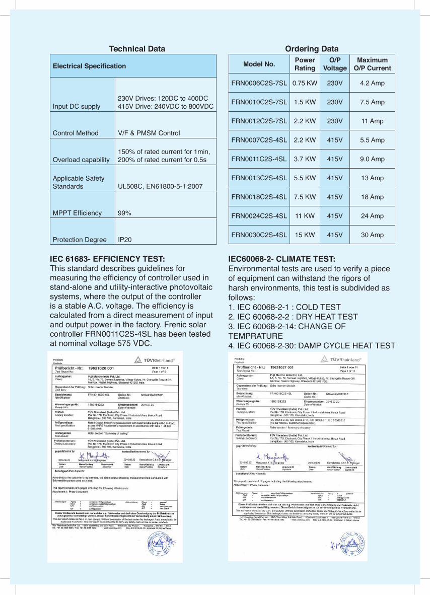
Ordering Data
Model No. Power Rating
O/P Voltage
Maximum O/P Current
FRN0006C2S-7SL 0.75 KW 230V 4.2 Amp
FRN0010C2S-7SL 1.5 KW 230V 7.5 Amp
FRN0012C2S-7SL 2.2 KW 230V 11 Amp
FRN0007C2S-4SL 2.2 KW 415V 5.5 Amp
FRN0011C2S-4SL 3.7 KW 415V 9.0 Amp
FRN0013C2S-4SL 5.5 KW 415V 13 Amp
FRN0018C2S-4SL 7.5 KW 415V 18 Amp
FRN0024C2S-4SL 11 KW 415V 24 Amp
FRN0030C2S-4SL 15 KW 415V 30 Amp
Technical Data
Electrical Specification
Input DC supply230V Drives: 120DC to 400DC415V Drive: 240VDC to 800VDC
Control Method V/F & PMSM Control
Overload capability150% of rated current for 1min,200% of rated current for 0.5s
Applicable Safety Standards UL508C, EN61800-5-1:2007
MPPT Efficiency 99%
Protection Degree IP20
IEC 61683- EFFICIENCY TEST:This standard describes guidelines for measuring the efficiency of controller used in stand-alone and utility-interactive photovoltaic systems, where the output of the controller is a stable A.C. voltage. The efficiency is calculated from a direct measurement of input and output power in the factory. Frenic solar controller FRN0011C2S-4SL has been tested at nominal voltage 575 VDC.
IEC60068-2- CLIMATE TEST:Environmental tests are used to verify a piece of equipment can withstand the rigors of harsh environments, this test is subdivided as follows:1. IEC 60068-2-1 : COLD TEST2. IEC 60068-2-2 : DRY HEAT TEST3. IEC 60068-2-14: CHANGE OF TEMPRATURE4. IEC 60068-2-30: DAMP CYCLE HEAT TEST
Fuji Electric India Pvt. Ltd.409-410, Meadows, Sahar Plaza, Andheri Kurla Rd, Andheri (E), Mumbai-400059,Tel: +91-022-40104870/71, 42524850Fuji Electric India Drive Factory.Block No. I-6, Sumeet Logistics & Industrial Park, Nashik Highway, Village Kukse,Taluka Bhiwandi,-421302 District - Thane Maharashtra India.Tel : 8879090765/ 8879042235E-mail: [email protected]
Fuji Electric Co., Ltd.
(2) Connected to the AC supply inputs and N(-). In this case the precharging circuit of the inverter is used, limiting the initial charging current of the inverter DC link capacitor. In this case be aware that the maximum frequency of charging cycles is two times per hour. When using this connection the current rating of the input rectifier must be considered. Please consult Fuji Electric to make the inverter selection.
Figure 6-2-2 Wiring diagram when inverter is supplied from PV panel connected to AC input and N(-) terminals.
MCCB (Note 8)
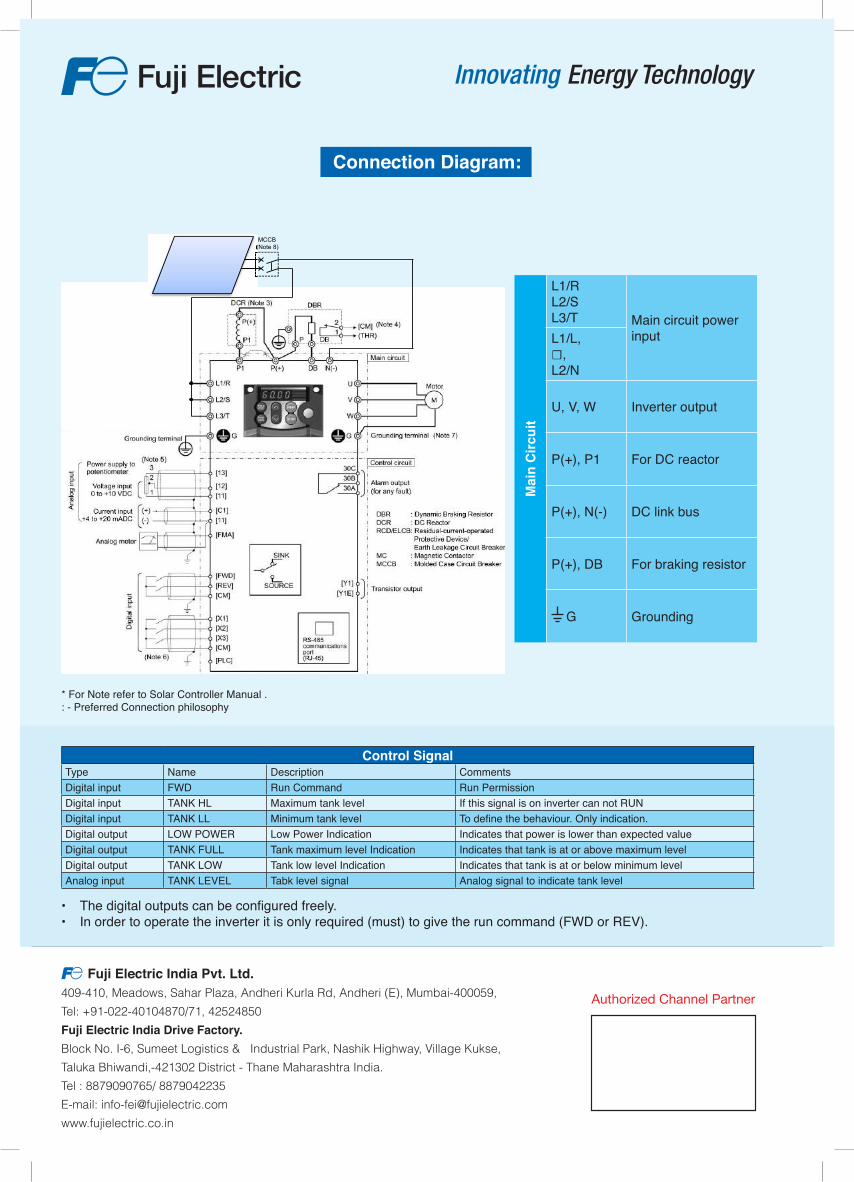
Connection Diagram:
• The digital outputs can be configured freely.• In order to operate the inverter it is only required (must) to give the run command (FWD or REV).
Control SignalType Name Description CommentsDigital input FWD Run Command Run PermissionDigital input TANK HL Maximum tank level If this signal is on inverter can not RUNDigital input TANK LL Minimum tank level To define the behaviour. Only indication.Digital output LOW POWER Low Power Indication Indicates that power is lower than expected valueDigital output TANK FULL Tank maximum level Indication Indicates that tank is at or above maximum levelDigital output TANK LOW Tank low level Indication Indicates that tank is at or below minimum levelAnalog input TANK LEVEL Tabk level signal Analog signal to indicate tank level
Mai
n C
ircui
t
L1/RL2/SL3/T Main circuit power
inputL1/L,☐,L2/N
U, V, W Inverter output
P(+), P1 For DC reactor
P(+), N(-) DC link bus
P(+), DB For braking resistor
G Grounding
* For Note refer to Solar Controller Manual . : - Preferred Connection philosophy