Advanced BAW Filter Technology and Its Impact on 5G
10
August 2020 | Subject to change without notice. 1 of 10 www.qorvo.com Advanced BAW Filter Technology and Its Impact on 5G Abstract The global rollout of 5G, and the rapid expansion of the Internet of Things, create significant new RF filtering challenges. Qorvo’s bulk acoustic wave (BAW) filter technology is advancing to overcome these challenges. Among the chief developments: BAW filters are evolving to support higher frequencies and increased bandwidth for the new 5G and Wi-Fi band expansion. Complex multi-filter modules (multiplexers and antennaplexers) are being used to address RF system challenges, particularly with 5G. Additionally, a smaller uBAW (micro-BAW) form factor helps squeeze complex RF front end (RFFE) architectures into the limited space available in handsets and Internet of Things (IoT) devices. At the same time, Qorvo’s BAW technology helps to mitigate the problem of heat dissipation associated with higher frequencies and smaller form factors. Introduction Qorvo’s BAW RF filters play indispensable roles in wireless devices and infrastructure. They ensure isolation between the ever-growing number of frequency bands and offer low insertion loss to support device performance requirements. However, the global rollout of 5G, and the evolution of other wireless standards such as Wi-Fi, create new filtering challenges that are beyond the capabilities of traditional acoustic filters. Significant advances in BAW technology were required to solve these new challenges. WHITE PAPER
Transcript of Advanced BAW Filter Technology and Its Impact on 5G
August 2020 | Subject to change without notice. 1 of 10 www.qorvo.com
Advanced BAW Filter Technology and Its Impact on 5G
Abstract
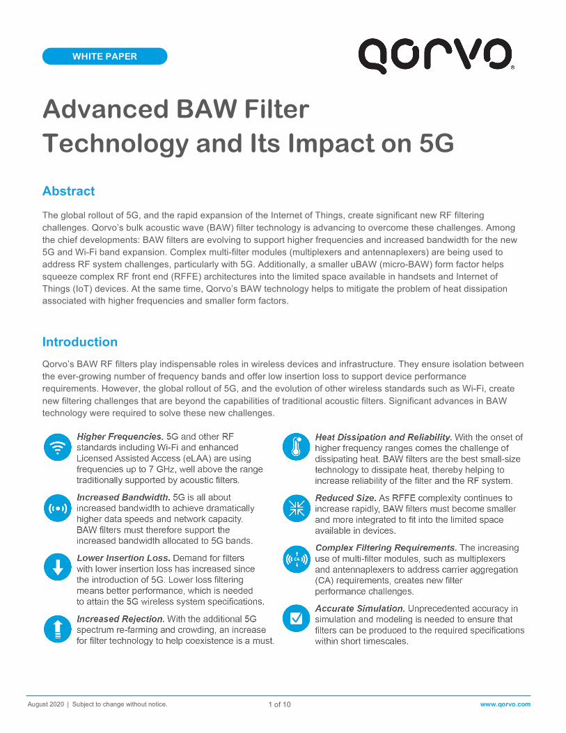
The global rollout of 5G, and the rapid expansion of the Internet of Things, create significant new RF filtering challenges. Qorvo’s bulk acoustic wave (BAW) filter technology is advancing to overcome these challenges. Among the chief developments: BAW filters are evolving to support higher frequencies and increased bandwidth for the new 5G and Wi-Fi band expansion. Complex multi-filter modules (multiplexers and antennaplexers) are being used to address RF system challenges, particularly with 5G. Additionally, a smaller uBAW (micro-BAW) form factor helps squeeze complex RF front end (RFFE) architectures into the limited space available in handsets and Internet of Things (IoT) devices. At the same time, Qorvo’s BAW technology helps to mitigate the problem of heat dissipation associated with higher frequencies and smaller form factors.
Introduction
Qorvo’s BAW RF filters play indispensable roles in wireless devices and infrastructure. They ensure isolation between the ever-growing number of frequency bands and offer low insertion loss to support device performance requirements. However, the global rollout of 5G, and the evolution of other wireless standards such as Wi-Fi, create new filtering challenges that are beyond the capabilities of traditional acoustic filters. Significant advances in BAW technology were required to solve these new challenges.
WHITE PAPER
WHITE PAPER: Revolutionary BAW Filter Technology and Its Impact on 5G
August 2020 | Subject to change without notice. t
2 of 10 www.qorvo.com
Key Properties of BAW
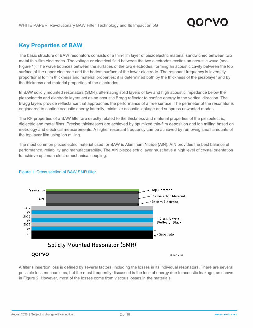
The basic structure of BAW resonators consists of a thin-film layer of piezoelectric material sandwiched between two metal thin-film electrodes. The voltage or electrical field between the two electrodes excites an acoustic wave (see Figure 1). The wave bounces between the surfaces of the two electrodes, forming an acoustic cavity between the top surface of the upper electrode and the bottom surface of the lower electrode. The resonant frequency is inversely proportional to film thickness and material properties; it is determined both by the thickness of the piezolayer and by the thickness and material properties of the electrodes.
In BAW solidly mounted resonators (SMR), alternating solid layers of low and high acoustic impedance below the piezoelectric and electrode layers act as an acoustic Bragg reflector to confine energy in the vertical direction. The Bragg layers provide reflectance that approaches the performance of a free surface. The perimeter of the resonator is engineered to confine acoustic energy laterally, minimize acoustic leakage and suppress unwanted modes.
The RF properties of a BAW filter are directly related to the thickness and material properties of the piezoelectric, dielectric and metal films. Precise thicknesses are achieved by optimized thin-film deposition and ion milling based on metrology and electrical measurements. A higher resonant frequency can be achieved by removing small amounts of the top layer film using ion milling.
The most common piezoelectric material used for BAW is Aluminum Nitride (AlN). AIN provides the best balance of performance, reliability and manufacturability. The AlN piezoelectric layer must have a high level of crystal orientation to achieve optimum electromechanical coupling. Figure 1. Cross section of BAW SMR filter.
A filter’s insertion loss is defined by several factors, including the losses in its individual resonators. There are several possible loss mechanisms, but the most frequently discussed is the loss of energy due to acoustic leakage, as shown in Figure 2. However, most of the losses come from viscous losses in the materials.

WHITE PAPER: Revolutionary BAW Filter Technology and Its Impact on 5G
August 2020 | Subject to change without notice. t
3 of 10 www.qorvo.com
Figure 2. Possible acoustic leakage mechanisms in SMR BAW.
The Importance of Electro-Mechanical CouplingSuperior coupling is imperative to meet high-frequency passband requirements for 5G and higher frequency Wi-Fi. The achievable width of the filter passband is determined by the electromechanical coupling coefficient, k2
eff. Maximizing k2
eff is one of the biggest challenges in thin-film BAW design.
The k2eff of a BAW resonator can be obtained from the resonance and anti-resonance frequencies measured from its
impedance response. The design of the resonator layers can greatly enhance or degrade the coupling.
Filter TopologiesNetworks of resonators can be designed to achieve various filter characteristics. BAW filters can be classified into two major topology categories: ladder and lattice. A lattice is a balanced topology, while a ladder is an unbalanced topology (see Figure 3).
Each topology has its advantages and disadvantages; however, the ladder topology is the most common. To achieve the required bandwidth, the shunt elements are tuned to a lower frequency than the series elements. The out-of-band rejection is determined by the number of elements and the net capacitor divider. To meet a desired rejection there is typically an optimum topology.

WHITE PAPER: Revolutionary BAW Filter Technology and Its Impact on 5G
August 2020 | Subject to change without notice. t
4 of 10 www.qorvo.com
Figure 3. Ladder, lattice and ladder-lattice configurations.
High-Frequency BAW
5G uses new frequency bands that are well above those traditionally used for 4G LTE, and above the range customarily supported by BAW filters. These include new 5G Frequency Range 1 (FR1) and Frequency Range 2 (FR2) bands as shown in Figure 4 below. The upper limit of the Wi-Fi spectrum is also being extended above 7 GHz. Evolving BAW technology to support these considerably higher frequencies requires solving several technology challenge. Such as:
Figure 4. Frequency bands for major wireless standards.

WHITE PAPER: Revolutionary BAW Filter Technology and Its Impact on 5G
August 2020 | Subject to change without notice. t
5 of 10 www.qorvo.com
Increasing filter bandwidth requires enhanced coupling
between the resonators in the filter.
Creating Thinner Layers. The ability to create thinner layers, with accurate control over thickness and uniformity, is critical to support higher frequencies. The layer thickness determines the frequency response of the filter: thickness is inversely proportional to frequency. At high frequencies, the layers must be extremely thin. Small variations in thickness have a major impact on the filter’s frequency response; variations of just a few nanometers will create an unacceptable deviation in the response. For example, one nanometer of tungsten on a 5 GHz filter results in a frequency shift of approximately 10 MHz. Qorvo’s BAW engineers were able to solve these challenges, capitalizing on the experience from producing and selling more than 20 billion BAW filters over the last 10 years.
Minimizing Losses. Maintaining low resonator loss in acoustic filters becomes inherently more difficult at higher frequencies, for a variety of different reasons. First, material losses generally increase with higher frequencies. In addition, as the layers within the resonators become thinner to support higher-frequency operation, the resonators must become smaller in area to maintain the same capacitance. Unfortunately, this means that the ratio of resonator perimeter to area increases, which makes the resonator more prone to loss lateral through acoustic leakage. Mitigating above challenges requires careful engineering of the resonator structure and a clear understanding of the underlying physics. Qorvo’s BAW engineers have addressed these hurdles, resulting in lower insertion losses and steeper filter skirts.
Increased Bandwidth
A key advantage of the new higher-frequency bands allocated for 5G is that they offer much more bandwidth than is available in lower-frequency spectrum. 5G uses that additional bandwidth to deliver higher data rates and increase network capacity. As a result, 5G BAW filters must not only be able to operate at higher frequencies than previous filter generations, they must also be able to support those frequencies with much greater bandwidth.
Increasing filter bandwidth requires enhanced piezo-electric coupling. The use of Scandium-doped AlN piezo layers has been key to overcoming this problem – however, filter manufacturing becomes more challenging in comparison to regular AlN.
Key factors that influence piezoelectric coupling in BAW resonators are the piezo material, piezo layer quality, electrode configuration, acoustic reflector and parasitics.
Attaining perfect deposition for the piezo layer is challenging. A highly tuned pulsed DC magnetron sputtering process has proven to be the best choice in attaining a suitable layer for quality high-volume manufacturing.
The electrode configuration also significantly affects coupling. The thickness of the electrodes relative to the piezo layer must be optimized to meet the filter’s frequency and performance requirements. For each electrode material, there is an optimum thickness ratio that delivers the highest coupling coefficient (k2
eff).
Filters for 5G bands n77 (3.3-4.2 GHz), n78 (3.3-3.8 GHz) and n79 (4.4-5 GHz) require wide bandwidth and benefit greatly from optimized coupling. Enhanced coupling is also required when designing multiplexers for CA applications.
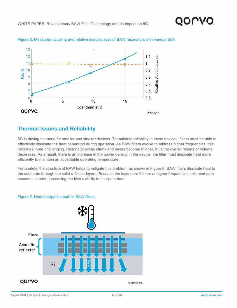
By using Sc-doped AlN, filter designers can increase coupling while keeping losses constant, as shown in Figure 5 below. Choosing the right percentage of Sc allows for, a good compromise between filter skirt steepness and bandwidth.
WHITE PAPER: Revolutionary BAW Filter Technology and Its Impact on 5G
August 2020 | Subject to change without notice. t
6 of 10 www.qorvo.com
Figure 5. Measured coupling and relative acoustic loss of BAW resonators with various Sc%.
Thermal Issues and Reliability
5G is driving the need for smaller and sleeker devices. To maintain reliability in these devices, filters must be able to effectively dissipate the heat generated during operation. As BAW filters evolve to address higher frequencies, this becomes more challenging. Resonator areas shrink and layers become thinner, thus the overall resonator volume decreases. As a result, there is an increase in the power density in the device; the filter must dissipate heat more efficiently to maintain an acceptable operating temperature.
Fortunately, the structure of BAW helps to mitigate this problem, as shown in Figure 6. BAW filters dissipate heat to the substrate through the solid reflector layers. Because the layers are thinner at higher frequencies, this heat path becomes shorter, increasing the filter’s ability to dissipate heat.
Figure 6. Heat dissipation path in BAW filters.

WHITE PAPER: Revolutionary BAW Filter Technology and Its Impact on 5G
August 2020 | Subject to change without notice. t
7 of 10 www.qorvo.com
Reducing Size
RFFE complexity continues to increase rapidly, as shown in Figure 7 – 5G accelerates that process, due to the addition of new bands as well as new requirements such as 4x4 MIMO. At the same time, space allocated to the RFFE in handsets is actually shrinking as smartphone makers cram in more features that are desirable to consumers, such as bigger batteries and more-sophisticated cameras.
Figure 7. Mobile device front-end module with CA filter technology.
These trends mean there is constant pressure to make all RF components, including filters, smaller and more highly integrated. The growth of the IoT also adds to demand for very small filters and other RF components that can fit into tiny IoT devices.
Qorvo’s uBAW, shown in Figure 8, is a key step in a continuing strategy to reduce filter size. In traditional wafer level packaged (WLP) BAW filters, less than half of the total area of the filter is occupied by the resonators. The periphery of the filter, which includes the Cu-Sn input-output pillars, accounts for about 40% of the total area. uBAW almost eliminates this peripheral area entirely by placing the pillars on top of the WLP roof. This reduces the total size of the filter by an average of 30%. An example filter based on uBAW to reduce size is the Qorvo QPQ2200Q, a fully 50 Ohm matched automotive tested Wi-Fi and LTE coexistence filter with a footprint of 1.1x0.9x0.585 mm.
Figure 8. Simplified cross-section of legacy WLP BAW versus uBAW.
WHITE PAPER: Revolutionary BAW Filter Technology and Its Impact on 5G
August 2020 | Subject to change without notice. t
8 of 10 www.qorvo.com
Complex Filters: Multiplexers and Antennaplexers
Complex modules that combine several filters have become important RFFE elements in recent years and play even bigger roles in 5G.
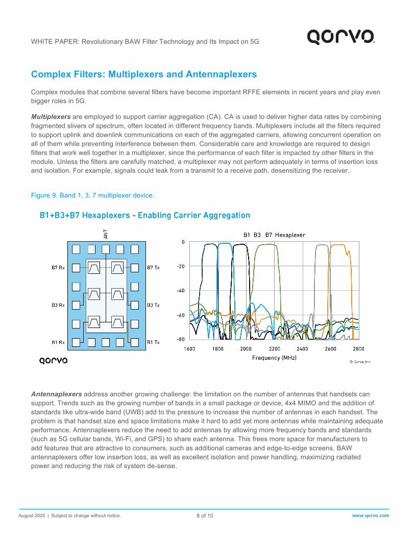
Multiplexers are employed to support carrier aggregation (CA). CA is used to deliver higher data rates by combining fragmented slivers of spectrum, often located in different frequency bands. Multiplexers include all the filters required to support uplink and downlink communications on each of the aggregated carriers, allowing concurrent operation on all of them while preventing interference between them. Considerable care and knowledge are required to design filters that work well together in a multiplexer, since the performance of each filter is impacted by other filters in the module. Unless the filters are carefully matched, a multiplexer may not perform adequately in terms of insertion loss and isolation. For example, signals could leak from a transmit to a receive path, desensitizing the receiver.
Figure 9. Band 1, 3, 7 multiplexer device.
Antennaplexers address another growing challenge: the limitation on the number of antennas that handsets can support. Trends such as the growing number of bands in a small package or device, 4x4 MIMO and the addition of standards like ultra-wide band (UWB) add to the pressure to increase the number of antennas in each handset. The problem is that handset size and space limitations make it hard to add yet more antennas while maintaining adequate performance. Antennaplexers reduce the need to add antennas by allowing more frequency bands and standards (such as 5G cellular bands, Wi-Fi, and GPS) to share each antenna. This frees more space for manufacturers to add features that are attractive to consumers, such as additional cameras and edge-to-edge screens. BAW antennaplexers offer low insertion loss, as well as excellent isolation and power handling, maximizing radiated power and reducing the risk of system de-sense.

WHITE PAPER: Revolutionary BAW Filter Technology and Its Impact on 5G
August 2020 | Subject to change without notice. t
9 of 10 www.qorvo.com
Figure 10. Examples of Qorvo antennaplexer devices.
Simulation Optimization tools are ubiquitous in electronic design. BAW filter design optimization requires a scalable model that precisely predicts performance over a wide frequency range. The rapidly increasing complexity of RFFE architectures requires an unprecedented level of accuracy in simulation and modeling. The time allotted to develop a complex integrated RF module, from defining the required functionality to producing a final qualified sample, is very short and leaves no room for trial and error. Therefore, it is vital to be able to have extremely accurate methods for simulating the performance of each functional block during design, to provide confidence that the final product will match the performance of the model.
Figure 11. Comparison between simulation and measured data for SMR BAW.

WHITE PAPER: Revolutionary BAW Filter Technology and Its Impact on 5G
August 2020 | Subject to change without notice. t
10 of 10 www.qorvo.com
Today Qorvo’s BAW engineers have simulation methods to accurately produce results that match a final measured design. Sophisticated 3D electro-magnetic simulation allows in-depth modeling to optimize performance. This helps to ensure that the final measured performance matches the design performance as shown in Figure 11 above.
Conclusion Qorvo’s BAW filter technology has been advancing to provide a formidable solution to the filtering challenges created by the global rollout of 5G. BAW filters are evolving to support higher frequencies and increased bandwidth with ever increasing performance. They are becoming smaller, more highly integrated and they are being incorporated into a growing range of complex multiplexers and antennaplexers. Highly accurate simulation methods are facilitating the rapid development of new filters and modules to meet stringent requirements. BAW technology will continue to evolve to address the future challenges presented by 5G and other wireless standards.
© Qorvo US, Inc. | QORVO is a registered trademark of Qorvo US, Inc.