ADMINISTRATORS GUIDE EPISUITE 6 - IDentiphoto Static Text Fields - Dynamic Text Fields - Moving...
18
ADMINISTRATORS GUIDE EPISUITE 6 A quick tutorial on how to set up and ® implement Episuite Software created by Specialists in IDentification IDentiphoto ® 1810 Joseph Lloyd Pkwy. Willoughby, OH 44094 Phone: (800) 860-9111 Fax: (440) 306-9001 e-mail: [email protected] web: www.identiphoto.com
Transcript of ADMINISTRATORS GUIDE EPISUITE 6 - IDentiphoto Static Text Fields - Dynamic Text Fields - Moving...

ADMINISTRATORS
GUIDE
EPISUITE 6A quick tutorial on how to set up and
®implement Episuite Software
created by
Specialists in IDentification
IDentiphoto®
1810 Joseph Lloyd Pkwy.Willoughby, OH 44094Phone: (800) 860-9111Fax: (440) 306-9001
e-mail: [email protected]: www.identiphoto.com
TABLE OF CONTENTS
Program InstallationDatabase CreationGuard Tool Database Utility
Page 2
Page 3 & 4
Page 6
Page 7
Page 8
Page 9
Page 11
Page 12
Page 13 & 14
Page 15 & 16
Page 1
Guard Tool Database Utility - (cont.)- (adding & deleting fields and indexes)
Epi Designer- Connecting to database- New ID Badge Template- Paper or Teslin - Page Setup
Adding Objects to Badge Design (cont.)- Static Images or Logos- Magnetic Stripe Data- Defining Expressions
Adding Objects to Badge Design- Dynamic Images- Geometric Shapes- Bar Codes
Adding Objects to Badge Design (cont.)- Static Text Fields- Dynamic Text Fields- Moving Objects- Change Fill, Line or Text Colors
Re-sizing ObjectsRotating ObjectsAligning ObjectsPlacing Background on CardSwitch Views (Front & Back)
GuardCard Setup- Connecting to Database- Adjusting Database Settings
Adding Fields to Input Screen
Card Printer Encoder SetupAdding UsersCard Format SetupImage Capture Setup
Guard Tool Reports- Running Reports
Page 5 Button/Field Summary
ADMINISTRATOR GUIDE
This guide assumes the administrator has a good understanding of the windows environment. This manual will provide you with a general step-by-step guide to setting up the Episuite software. For more detailedhelp on each module please refer to the online help provided by the software. This manual is based on alocal, single user installation.
GUARD TOOL DATABASE UTILITY
1. Place the hardware key on LPT port or USB port depending on which key you ordered.2. Insert software disk; auto run should start software installation. Follow instructions on screen. (If auto run fails, click on START, RUN, BROWSE then navigate to CDrom drive and choose SETUP.exe)
The software is installed in the c:\Program Files\Imageware Systems\Episuite\6\ directory. The default databases are located in the c:\Program Files\Imageware Systems\Episuite\6\DB folder (Episuite.mdb & template.mdb).
All program modules are located under START, PROGRAMS, EPI Suite 6
1. Open WINDOWS EXPLORE and browse to c:\Program Files\Imageware Systems\Episuite\6\DB folder.2. Make a copy of the template.mdb file3. Rename copy of template.mdb file to the name that you’d like for your database
You have just created a blank database that will store the data used to create ID badges. This database contains a number of default fields. Most users don’t need all of these fields and usually need to add their own. This is accomplished using the GUARDTOOL DATABASE UTILITY module.
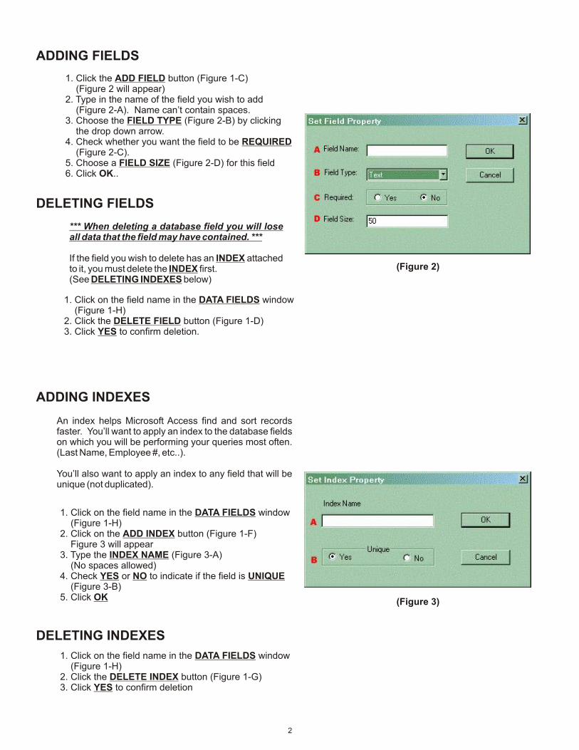
1. Click Windows START button2. Select PROGRAMS3. Select EPI Suite 64. Select GUARDTOOL DATABASE UTILITY5. Click the CHANGE DATABASE button and BROWSE out and select the database file that you created, click OPEN, OPEN.6. Click the EPI Suite DB UTILITY button (Figure 1 appears)
DATABASE FILE CREATION
(Figure 1)
With this utility you can add fields to the person or card tables (Figure 1-A). The fields that are currently in the table selected are shown in the large white window (Figure 1-H). This is where you add and remove fields from the database just created. Continue adding and deleting fields until you have all the fields you need.
You can also do a repair and compact on the database from here by clicking on the OPTIMIZE DATABASE button (Figure 1-B)
1
ADDING FIELDS
(Figure 2)
(Figure 3)
1. Click the ADD FIELD button (Figure 1-C) (Figure 2 will appear)2. Type in the name of the field you wish to add (Figure 2-A). Name can’t contain spaces.3. Choose the FIELD TYPE (Figure 2-B) by clicking the drop down arrow.4. Check whether you want the field to be REQUIRED (Figure 2-C).5. Choose a FIELD SIZE (Figure 2-D) for this field6. Click OK..
ADDING INDEXES
An index helps Microsoft Access find and sort records faster. You’ll want to apply an index to the database fields on which you will be performing your queries most often. (Last Name, Employee #, etc..).
You’ll also want to apply an index to any field that will be unique (not duplicated).
1. Click on the field name in the DATA FIELDS window (Figure 1-H)2. Click on the ADD INDEX button (Figure 1-F) Figure 3 will appear3. Type the INDEX NAME (Figure 3-A) (No spaces allowed)4. Check YES or NO to indicate if the field is UNIQUE (Figure 3-B)5. Click OK
DELETING INDEXES
1. Click on the field name in the DATA FIELDS window (Figure 1-H)2. Click the DELETE INDEX button (Figure 1-G)3. Click YES to confirm deletion
DELETING FIELDS
1. Click on the field name in the DATA FIELDS window (Figure 1-H)2. Click the DELETE FIELD button (Figure 1-D)3. Click YES to confirm deletion.
*** When deleting a database field you will lose all data that the field may have contained. ***
If the field you wish to delete has an INDEX attached to it, you must delete the INDEX first.(See DELETING INDEXES below)
2
EPI DESIGNER - ID BADGE DESIGNThe EPI Designer module allows you to create ID badge templates. The design capabilities of this module are very limited. For more complex badge designs you will need to use a graphics program like CorelDraw or Adobe Illustrator. With EPI Designer you will be able to add static text fields, dynamic text (database) fields, image fields, logos, barcodes, and set up magnetic stripe encoding information.
EPI Designer can be used to create ID badge templates that will be printed to PVC using a PVC card printer, or to paper or teslin (with multiple badges per sheet) using an inkjet or color laser printer. A unique feature of EPI Designer is that each ID badge template stores all the printer settings used to produce that badge. It is recommended that you set you windows default printer to your PVC printer before opening the Epi Designer module.
This manual will give you a very basic tutorial on how to create ID badge templates. For more detailed information on the features of this module refer to the online help by pressing the F1 key. This tutorial also assumes that you are familiar with the printer you will be using and it’s settings.
CONNECTING TO DATABASE
1. Click FILE menu 2. Select NEW
This will open up the EPI Designer screen with a blank template based on the windows default printer.
(Figure 4a)
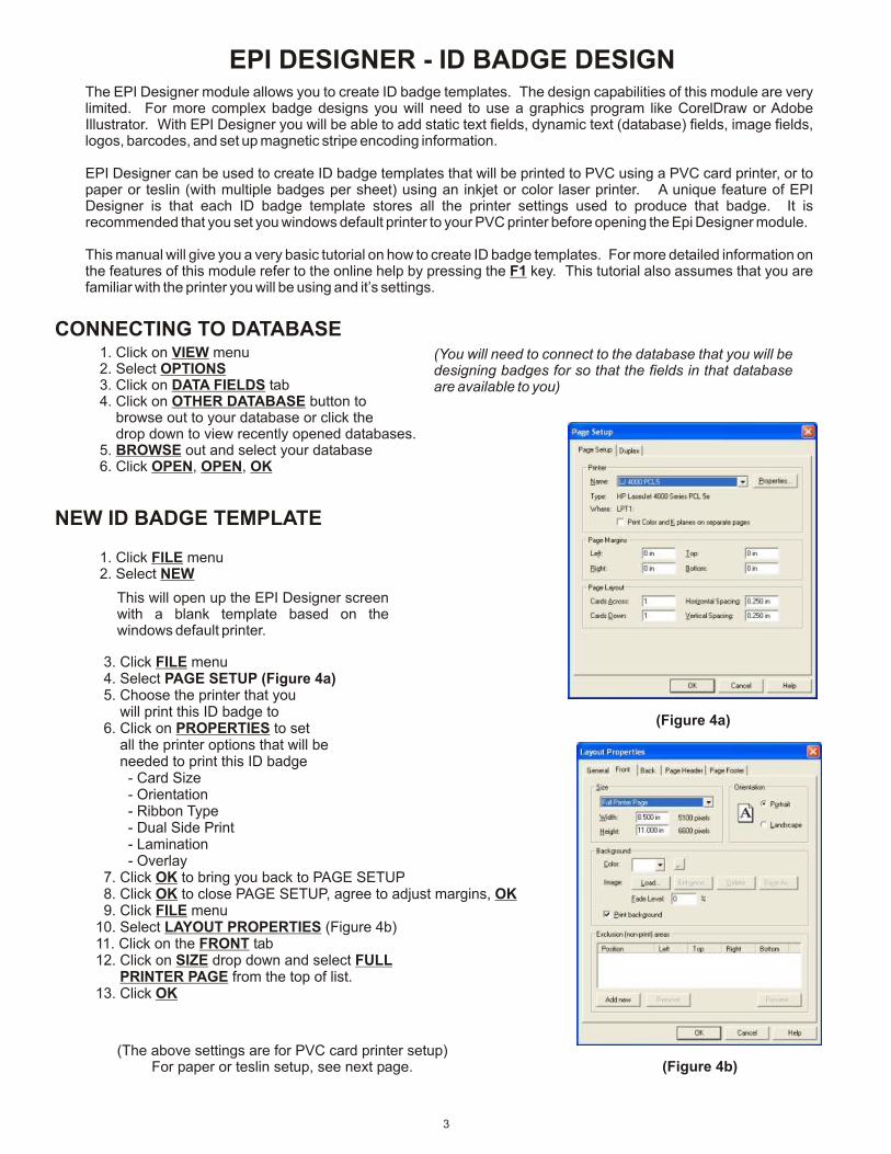
3. Click FILE menu 4. Select PAGE SETUP (Figure 4a) 5. Choose the printer that you will print this ID badge to 6. Click on PROPERTIES to set all the printer options that will be needed to print this ID badge - Card Size - Orientation - Ribbon Type - Dual Side Print - Lamination - Overlay 7. Click OK to bring you back to PAGE SETUP 8. Click OK to close PAGE SETUP, agree to adjust margins, OK 9. Click FILE menu10. Select LAYOUT PROPERTIES (Figure 4b)11. Click on the FRONT tab12. Click on SIZE drop down and select FULL PRINTER PAGE from the top of list.13. Click OK
1. Click on VIEW menu 2. Select OPTIONS 3. Click on DATA FIELDS tab 4. Click on OTHER DATABASE button to browse out to your database or click the drop down to view recently opened databases. 5. BROWSE out and select your database 6. Click OPEN, OPEN, OK
NEW ID BADGE TEMPLATE
(You will need to connect to the database that you will be designing badges for so that the fields in that database are available to you)
3
(Figure 4b)(The above settings are for PVC card printer setup)
For paper or teslin setup, see next page.

1. Click on FILE menu LAYOUT PROPERTIES and click on FRONT tab. (Figure 4b)2. Click CARD SIZE drop down and select CUSTOM SIZE, type in the WIDTH & HEIGHT (Figure 4b) of your card.3. Select the CARD ORIENTATION (Figure 4b)4. Click OK5. Click on FILE menu and then PAGE SETUP (Figure 4a)6. Fill out the PAGE MARGINS and PAGE LAYOUT sections.
7. Click OK
(You only need to measure the top & left margins. The right & bottom margins will automatically fill in based on all your previous settings)
PAPER OR TESLIN - Page Setup
4
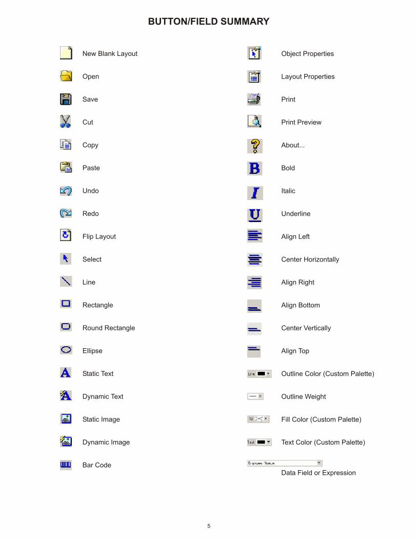
New Blank Layout
Open
Save
Cut
Copy
Paste
Undo
Redo
Flip Layout
Select
Line
Rectangle
Round Rectangle
Ellipse
Static Text
Dynamic Text
Static Image
Dynamic Image
Bar Code
5
Object Properties
Layout Properties
Print Preview
About...
Bold
Italic
Underline
Align Left
Center Horizontally
Align Right
Align Bottom
Center Vertically
Align Top
Outline Color (Custom Palette)
Outline Weight
Fill Color (Custom Palette)
Text Color (Custom Palette)
Data Field or Expression
BUTTON/FIELD SUMMARY
The design module allows you to add the following to your badge design.
1. Database fields & images (dynamic data)2. Static Text3. Basic Geometric shapes (circles, ovals, rectangles, etc...)4. Logo files or Backgrounds5. Barcodes6. Magnetic Stripe setup
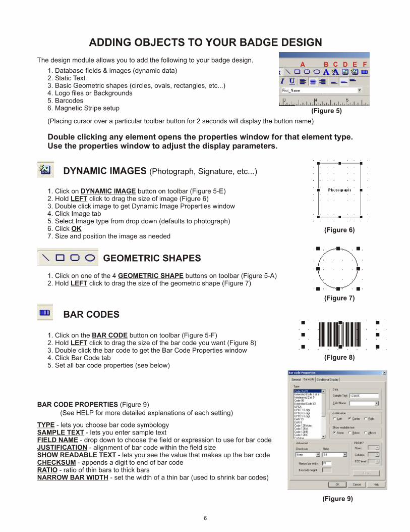
DYNAMIC IMAGES (Photograph, Signature, etc...)
1. Click on DYNAMIC IMAGE button on toolbar (Figure 5-E)2. Hold LEFT click to drag the size of image (Figure 6)3. Double click image to get Dynamic Image Properties window4. Click Image tab5. Select Image type from drop down (defaults to photograph)6. Click OK7. Size and position the image as needed
(Placing cursor over a particular toolbar button for 2 seconds will display the button name)
Double clicking any element opens the properties window for that element type.Use the properties window to adjust the display parameters.
(Figure 6)
ADDING OBJECTS TO YOUR BADGE DESIGN
GEOMETRIC SHAPES
(Figure 7)
1. Click on one of the 4 GEOMETRIC SHAPE buttons on toolbar (Figure 5-A)2. Hold LEFT click to drag the size of the geometric shape (Figure 7)
BAR CODES
(Figure 8)
1. Click on the BAR CODE button on toolbar (Figure 5-F)2. Hold LEFT click to drag the size of the bar code you want (Figure 8)3. Double click the bar code to get the Bar Code Properties window4. Click Bar Code tab5. Set all bar code properties (see below)
(Figure 9)
BAR CODE PROPERTIES (Figure 9)
TYPE - lets you choose bar code symbologySAMPLE TEXT - lets you enter sample textFIELD NAME - drop down to choose the field or expression to use for bar codeJUSTIFICATION - alignment of bar code within the field sizeSHOW READABLE TEXT - lets you see the value that makes up the bar codeCHECKSUM - appends a digit to end of bar codeRATIO - ratio of thin bars to thick barsNARROW BAR WIDTH - set the width of a thin bar (used to shrink bar codes)
(See HELP for more detailed explanations of each setting)
6
(Figure 5)
A B C D E F
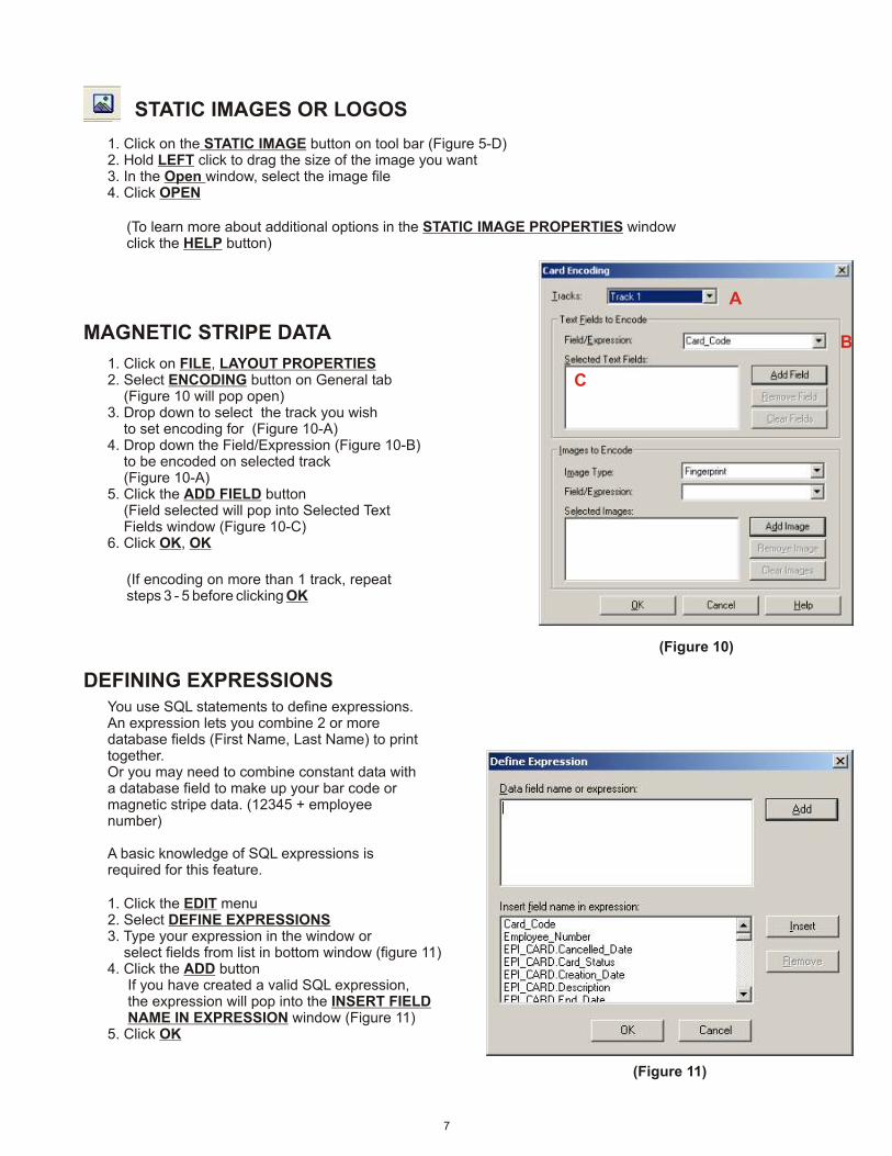
MAGNETIC STRIPE DATA
(Figure 10)
1. Click on FILE, LAYOUT PROPERTIES2. Select ENCODING button on General tab (Figure 10 will pop open)3. Drop down to select the track you wish to set encoding for (Figure 10-A)4. Drop down the Field/Expression (Figure 10-B) to be encoded on selected track (Figure 10-A)5. Click the ADD FIELD button (Field selected will pop into Selected Text Fields window (Figure 10-C)6. Click OK, OK
(If encoding on more than 1 track, repeat steps 3 - 5 before clicking OK
STATIC IMAGES OR LOGOS
1. Click on the STATIC IMAGE button on tool bar (Figure 5-D)2. Hold LEFT click to drag the size of the image you want3. In the Open window, select the image file4. Click OPEN
(To learn more about additional options in the STATIC IMAGE PROPERTIES windowclick the HELP button)
DEFINING EXPRESSIONS
1. Click the EDIT menu2. Select DEFINE EXPRESSIONS3. Type your expression in the window or select fields from list in bottom window (figure 11)4. Click the ADD button If you have created a valid SQL expression, the expression will pop into the INSERT FIELD NAME IN EXPRESSION window (Figure 11)5. Click OK
(Figure 11)
You use SQL statements to define expressions. An expression lets you combine 2 or more database fields (First Name, Last Name) to print together.Or you may need to combine constant data with a database field to make up your bar code or magnetic stripe data. (12345 + employee number)
A basic knowledge of SQL expressions is required for this feature.
7
A
B
C

DYNAMIC TEXT
1. Click on the DYNAMIC TEXT button on toolbar (Figure 5-C)2. Hold LEFT click to drag the size of the text box (Figure 12)3. Double click on the DATA FIELD4. Select the TEXT tab (Figure 14)5. Drop down the DATA FIELD NAME or EXPRESSION box6. Select the database field or expression to print7. Click OK
Check Automatically reduce font to fit and/or Wrap text to make longer text fit into the field size drawn. (Figures 13-A, 14-A)
(For more detailed information about the STATIC TEXT PROPERTIES or DYNAMIC TEXT PROPERTIES windows, click the HELP button in their respective windows)
1. Highlight the object by LEFT clicking on it2. Use the ARROW keys or click and drag to adjust position of object
1. Click the LINE, FILL or TEXT drop down on the toolbar (Figure 15) to display the custom color palette.2. Select the color
CUSTOM COLORS
FULL RGB SPECTRUM1. Double click the object to display the properties window2. Click the “...” button to display the full color palette for LINE, FILL SHADOW, or TEXT fields3. Choose a color from the BASIC color section or click on one of the custom colors you want to replace then create a new custom color on the right and click ADD TO CUSTOM COLORS4. Click OK
Most objects when created have an outline around the field. This is to help you with aligning fields to each other. This outline will print if not removed. To remove this outline, click the LINE drop down from the toolbar (Figure 5-C) and choose the no line color which looks like an “X”.
CHANGE FILL, LINE or TEXT COLORS
MOVING OBJECTS
STATIC TEXT
1. Click on the STATIC TEXT button on toolbar (Figure 5-B)2. Hold LEFT click to drag the size of the text box (Figure 12)3. Double click the TEXT field4. Select the TEXT tab (Figure 13)5. Type in the desired text6. Set additional properties for this element including font, size color, and justification.7. Click OK
(Figure 12)
(Figure 13)
Hint: To force a return when typing static text hold the CTRL key down and press the “J” key
8
(Highlight the object to change by LEFT clicking on it)
(Figure 15)
(Figure 14)
A
A
A
RE-SIZING OBJECTS
When an object has been selected, its size is shown by the black outline and the 8 black squares around it. (Figures 6,7,8,12)
To re-size the object LEFT click and hold one of the black squares and drag it. (Corner squares move 2 edges simultaneously, others move 1)
ROTATING OBJECTS
ALIGNING OBJECTS
1. Highlight the object by LEFT clicking on it2. Click the OBJECT menu3. Select ROTATE 90 DEGREES4. Select LEFT or RIGHT
1. Highlight the objects to be aligned by holding down the SHIFT key and LEFT clicking on each object2. Click the OBJECT menu3. Select ALIGN OR DISTRIBUTE4. Choose the type of alignment you wish to perform
SWITCHING BETWEEN FRONT & BACK OF BADGE1. Click the FLIP LAYOUT button (Figure 15-A)
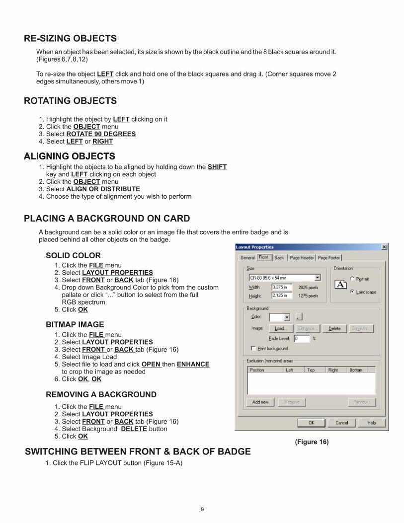
PLACING A BACKGROUND ON CARD
A background can be a solid color or an image file that covers the entire badge and is placed behind all other objects on the badge.
1. Click the FILE menu2. Select LAYOUT PROPERTIES3. Select FRONT or BACK tab (Figure 16)4. Drop down Background Color to pick from the custom pallate or click “...” button to select from the full RGB spectrum.5. Click OK
BITMAP IMAGE
ALIGNING OBJECTS
SOLID COLOR
REMOVING A BACKGROUND
1. Click the FILE menu2. Select LAYOUT PROPERTIES3. Select FRONT or BACK tab (Figure 16)4. Select Background DELETE button5. Click OK
9
(Figure 16)
1. Click the FILE menu2. Select LAYOUT PROPERTIES3. Select FRONT or BACK tab (Figure 16)4. Select Image Load5. Select file to load and click OPEN then ENHANCE to crop the image as needed6. Click OK, OK

Once you have finished designing your badge, save the design. We recommend that you create a folder called Badge Designs and put all your designs in this folder.
***** After you have created all your badge designs, you need to set them up in GUARDCARDunder the CARD FORMAT SETUP section under the FILE menu. (See page 13) ******
10
GUARDCARD SETUP
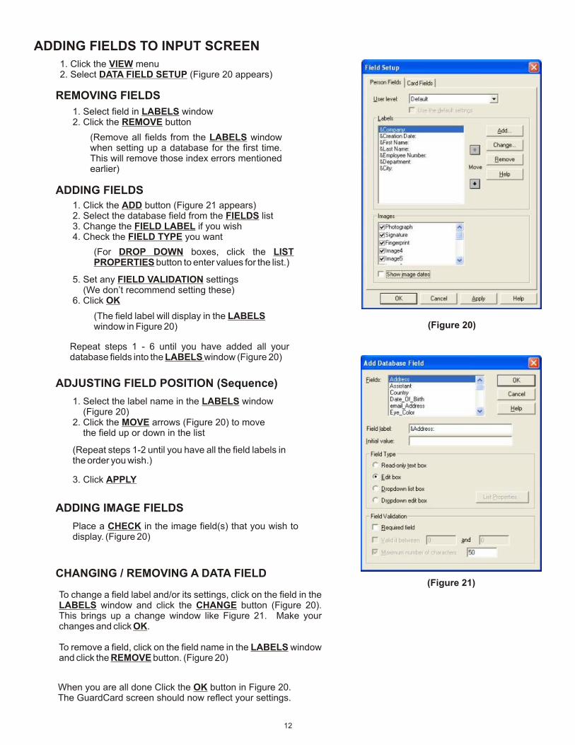
1. Click the VIEW menu2. Select OPTIONS (Figure’s 18 & 19)3. Click DATABASE tab4. Click the drop down (Figure 18-A) to see a list of recently opened databases or click the OTHER DATABASE button to search for one.5. Click the BROWSE button6. Select the database you’d like to make ID badges for7. Click OPEN, OPEN
**** When you click OK, you may get some INDEX error messages. Just accept them for now. They won’t come back once we
finish setting up GUARDCARD. ****
ADJUSTING DATABASE SETTINGS
GuardCard is the main module in which ID badge production is done. In this section we will explain the most common setup tasks. These tasks need to be performed for each database you created. For more detailed explanations of each setting click the HELP button or press F1 key. Most of these setup procedures are specific to each database and are stored in the database. This means that when you open up a different database, its settings are active.
Here is a list of steps to setting up GuardCard:
1. Attach to database you created2. Set database option settings3. Setup how database image fields are stored4. Setup Data Entry Screen5. Setup the type of encoder you’re using (optional)6. Setup the device used to capture images7. Add users8. Card Format setup
We recommend keeping most of the default settings. Below we list the settings we recommend be changed. If you’d like to learn more about each setting click the HELP button on each TAB.
DATABASE TAB (Figure 18)
1. UNCHECK - Save all DATE/TIME as GMT (most companies don’t use Greenwich Mean Time)
1. CHECK - Notify when no records are selected (This displays a window telling you no data was found during your query)2. UNCHECK - Manually validate cards after printing (This will make the Card Status VALID once printed)
GENERAL TAB (Figure 19)
CONNECTING TO/CHANGING DATABASES
11
(Click on VIEW menu then OPTIONS to adjust settings)(Figure 18)
(Figure 19)
(Figure 17)
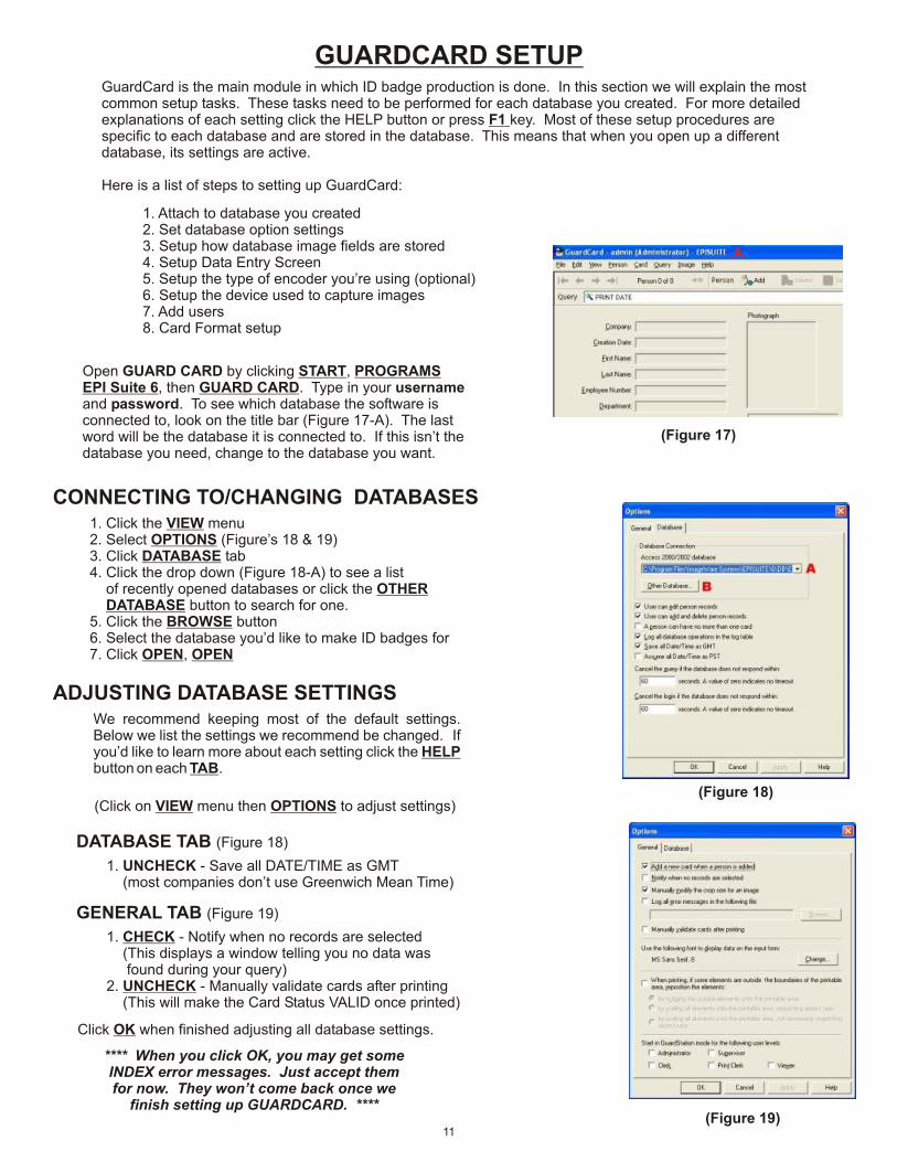
Open GUARD CARD by clicking START, PROGRAMSEPI Suite 6, then GUARD CARD. Type in your usernameand password. To see which database the software isconnected to, look on the title bar (Figure 17-A). The lastword will be the database it is connected to. If this isn’t thedatabase you need, change to the database you want.
Click OK when finished adjusting all database settings.
A
ADDING FIELDS TO INPUT SCREEN
(Figure 21)
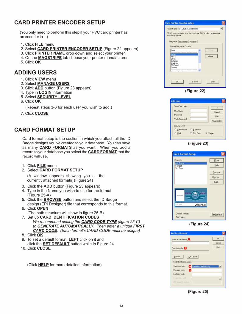
1. Click the VIEW menu2. Select DATA FIELD SETUP (Figure 20 appears)
ADJUSTING FIELD POSITION (Sequence)
1. Select field in LABELS window2. Click the REMOVE button
(Remove all fields from the LABELS windowwhen setting up a database for the first time.This will remove those index errors mentionedearlier)
(Figure 20)
REMOVING FIELDS
1. Click the ADD button (Figure 21 appears)2. Select the database field from the FIELDS list3. Change the FIELD LABEL if you wish4. Check the FIELD TYPE you want
(The field label will display in the LABELS window in Figure 20)
5. Set any FIELD VALIDATION settings (We don’t recommend setting these)6. Click OK
Repeat steps 1 - 6 until you have added all your database fields into the LABELS window (Figure 20)
ADDING FIELDS
(For DROP DOWN boxes, click the LIST PROPERTIES button to enter values for the list.)
1. Select the label name in the LABELS window (Figure 20)2. Click the MOVE arrows (Figure 20) to move the field up or down in the list
(Repeat steps 1-2 until you have all the field labels in the order you wish.)
3. Click APPLY
ADDING IMAGE FIELDS
Place a CHECK in the image field(s) that you wish to display. (Figure 20)
To change a field label and/or its settings, click on the field in the LABELS window and click the CHANGE button (Figure 20). This brings up a change window like Figure 21. Make your changes and click OK.
To remove a field, click on the field name in the LABELS window and click the REMOVE button. (Figure 20)
12
When you are all done Click the OK button in Figure 20. The GuardCard screen should now reflect your settings.
CHANGING / REMOVING A DATA FIELD
CARD PRINTER ENCODER SETUP
(Figure 22)
1. Click FILE menu2. Select CARD PRINTER ENCODER SETUP (Figure 22 appears)3. Click PRINTER NAME drop down and select your printer4. On the MAGSTRIPE tab choose your printer manufacturer5. Click OK
(You only need to perform this step if your PVC card printer has an encoder in it.)
ADDING USERS1. Click VIEW menu2. Select MANAGE USERS3. Click ADD button (Figure 23 appears)4. Type in LOGIN information5. Select SECURITY LEVEL6. Click OK
(Figure 23)
(Repeat steps 3-6 for each user you wish to add.)
7. Click CLOSE
CARD FORMAT SETUP
(Figure 24)
Card format setup is the section in which you attach all the ID Badge designs you’ve created to your database. You can have as many CARD FORMATS as you want. When you add a record to your database you select the CARD FORMAT that the record will use.
1. Click FILE menu 2. Select CARD FORMAT SETUP
(A window appears showing you all the currently attached formats) (Figure 24)
3. Click the ADD button (Figure 25 appears) 4. Type in the Name you wish to use for the format (Figure 25-A) 5. Click the BROWSE button and select the ID Badge design (EPI Designer) file that corresponds to this format. 6. Click OPEN (The path structure will show in figure 25-B) 7. Set up CARD IDENTIFICATION CODES We recommend setting the CARD CODE TYPE (figure 25-C) to GENERATE AUTOMATICALLY. Then enter a unique FIRST CARD CODE. (Each format’s CARD CODE must be unique) 8. Click OK 9. To set a default format, LEFT click on it and click the SET DEFAULT button while in Figure 2410. Click CLOSE
(Click HELP for more detailed information)
13
(Figure 25)
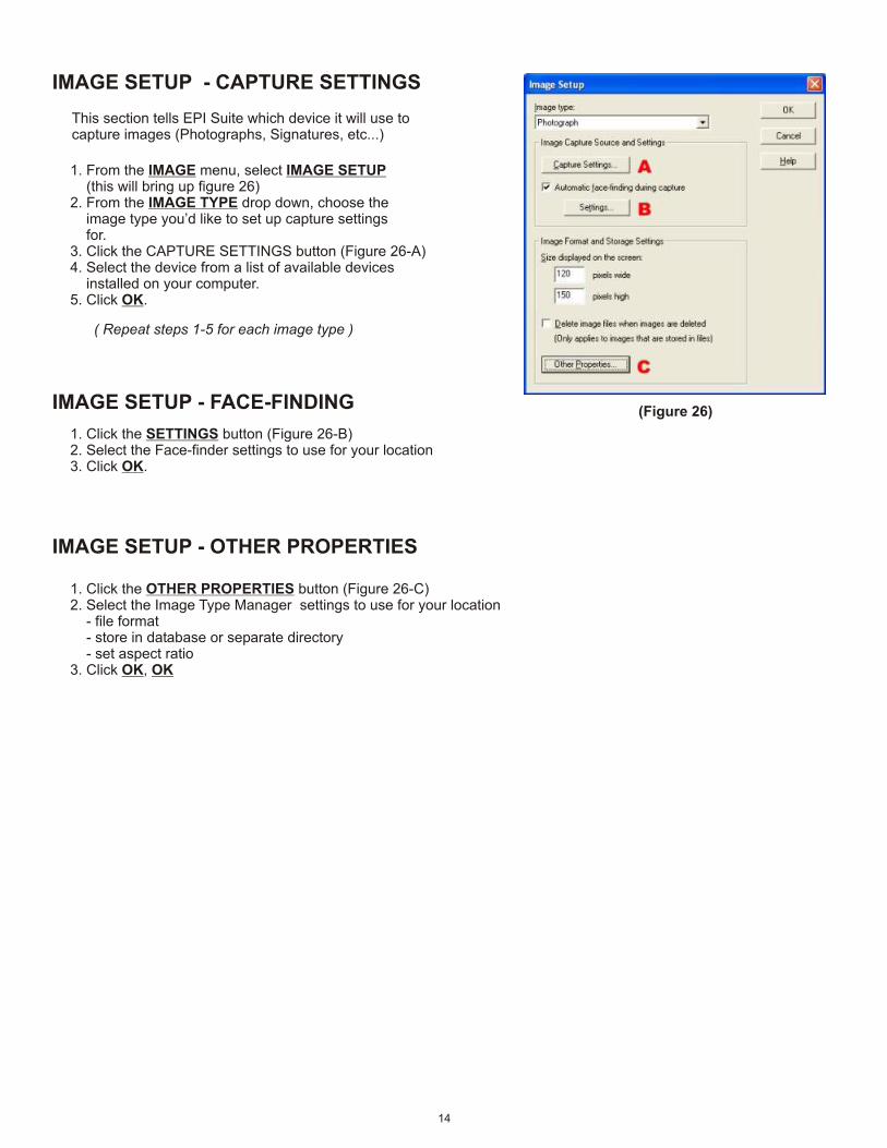
IMAGE SETUP - CAPTURE SETTINGS
(Figure 26)
This section tells EPI Suite which device it will use tocapture images (Photographs, Signatures, etc...)
1. From the IMAGE menu, select IMAGE SETUP (this will bring up figure 26)2. From the IMAGE TYPE drop down, choose the image type you’d like to set up capture settings for.3. Click the CAPTURE SETTINGS button (Figure 26-A)4. Select the device from a list of available devices installed on your computer.5. Click OK.
( Repeat steps 1-5 for each image type )
14
IMAGE SETUP - FACE-FINDING
1. Click the SETTINGS button (Figure 26-B)2. Select the Face-finder settings to use for your location3. Click OK.
IMAGE SETUP - OTHER PROPERTIES
1. Click the OTHER PROPERTIES button (Figure 26-C)2. Select the Image Type Manager settings to use for your location - file format - store in database or separate directory - set aspect ratio3. Click OK, OK
GUARDTOOL REPORTS
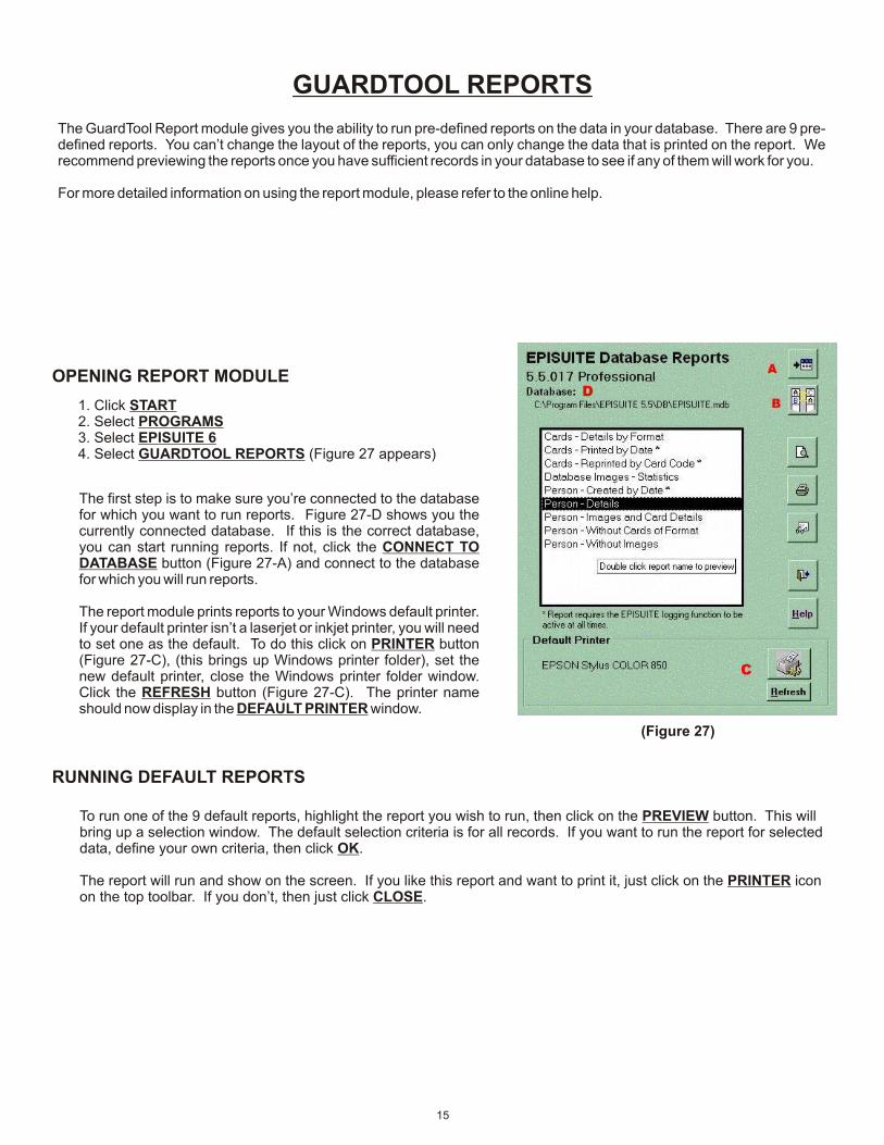
The GuardTool Report module gives you the ability to run pre-defined reports on the data in your database. There are 9 pre-defined reports. You can’t change the layout of the reports, you can only change the data that is printed on the report. We recommend previewing the reports once you have sufficient records in your database to see if any of them will work for you.
For more detailed information on using the report module, please refer to the online help.
(Figure 27)
OPENING REPORT MODULE
1. Click START2. Select PROGRAMS3. Select EPISUITE 64. Select GUARDTOOL REPORTS (Figure 27 appears)
The first step is to make sure you’re connected to the database for which you want to run reports. Figure 27-D shows you the currently connected database. If this is the correct database, you can start running reports. If not, click the CONNECT TO DATABASE button (Figure 27-A) and connect to the database for which you will run reports.
The report module prints reports to your Windows default printer. If your default printer isn’t a laserjet or inkjet printer, you will need to set one as the default. To do this click on PRINTER button (Figure 27-C), (this brings up Windows printer folder), set the new default printer, close the Windows printer folder window. Click the REFRESH button (Figure 27-C). The printer name should now display in the DEFAULT PRINTER window.
To run one of the 9 default reports, highlight the report you wish to run, then click on the PREVIEW button. This will bring up a selection window. The default selection criteria is for all records. If you want to run the report for selected data, define your own criteria, then click OK.
The report will run and show on the screen. If you like this report and want to print it, just click on the PRINTER icon on the top toolbar. If you don’t, then just click CLOSE.
RUNNING DEFAULT REPORTS
15
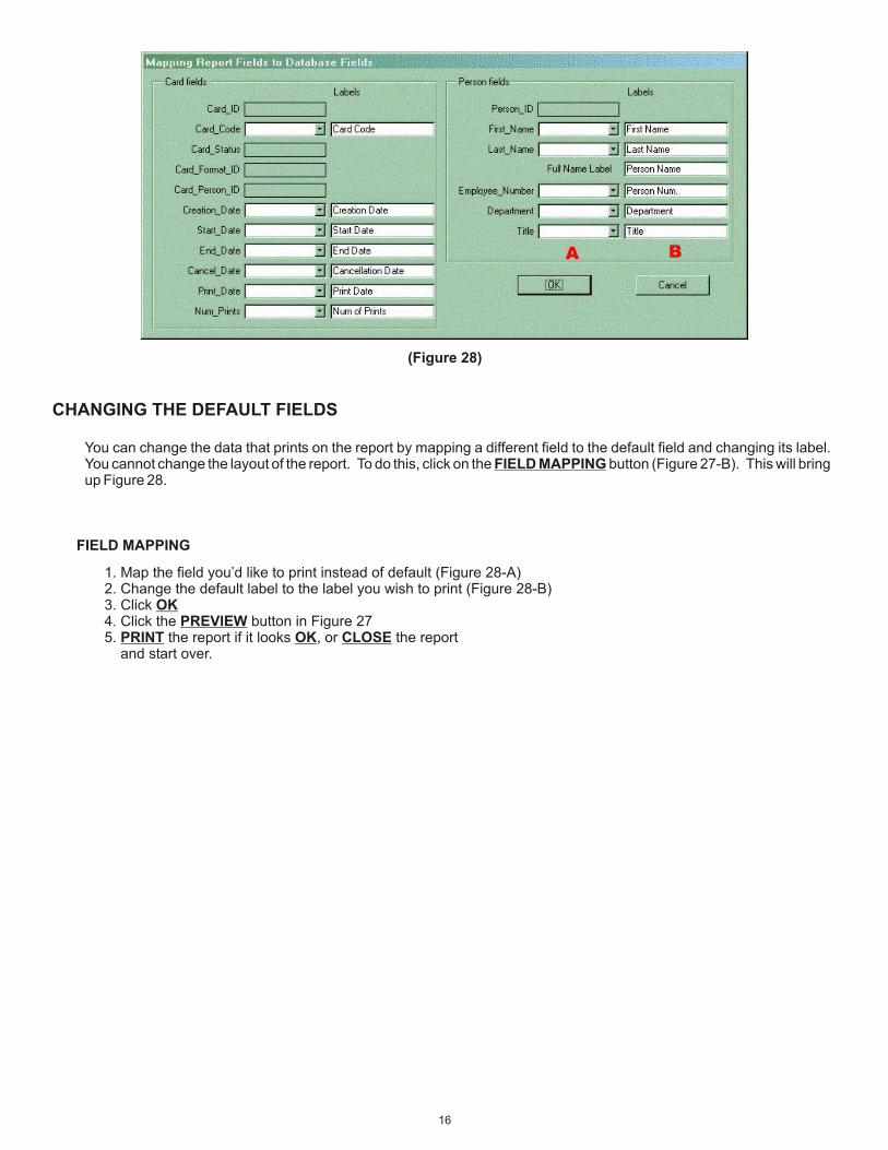
(Figure 28)
CHANGING THE DEFAULT FIELDS
You can change the data that prints on the report by mapping a different field to the default field and changing its label. You cannot change the layout of the report. To do this, click on the FIELD MAPPING button (Figure 27-B). This will bring up Figure 28.
FIELD MAPPING
1. Map the field you’d like to print instead of default (Figure 28-A)2. Change the default label to the label you wish to print (Figure 28-B)3. Click OK4. Click the PREVIEW button in Figure 275. PRINT the report if it looks OK, or CLOSE the report and start over.
16