Adjust Orientation Tool (EAOT) · 2019-01-13 · Adjust Orientation Tool (EAOT) The Adjust...
29
Adjust Orientation Tool (EAOT) The Adjust Orientation Tool (EAOT) has a transmission line that connects top and bottom logging instrument. The EAOT is able to adjust the Digital Micro Spherical Focused Laterolog Tool & Litho-Density Logging Tool pads in same direction result when logging in highly deviated wells. Maximum Temperature 400°F (204°C) Maximum Pressure 20,000 psi (140 MPa) Make-up Length 0.35 m (13.78 in) Shipping Length 0.7 m (27.55 in) Weight 33 Ib (15 kg) Maximum Tension 40,000 Ibf Maximum Compressive Force 10,000 Ibf
Transcript of Adjust Orientation Tool (EAOT) · 2019-01-13 · Adjust Orientation Tool (EAOT) The Adjust...

Adjust Orientation Tool (EAOT)
The Adjust Orientation Tool (EAOT) has a transmission line that connects top and bottom logging instrument. The EAOT is able to adjust the Digital Micro Spherical Focused Laterolog Tool & Litho-Density Logging Tool pads in same direction result when logging in highly deviated wells.
Maximum Temperature 400°F (204°C)
Maximum Pressure 20,000 psi (140 MPa)
Make-up Length 0.35 m (13.78 in)
Shipping Length 0.7 m (27.55 in)
Weight 33 Ib (15 kg)
Maximum Tension 40,000 Ibf
Maximum Compressive Force 10,000 Ibf

Array Induction Log (EAIL)
Array Induction Log (EAIL), based on electromagnetic theory, can be used with oil-based mud. water-based mud or air. The coil array mandrel consists of 1 transmitter coils and 7 receiver coils. The EAIL’s Transmitter Coil sends rectangular electromagnetic waves which generate stratum eddy currents, and the eddy currents will create an inductive voltage in the receiver coils. The processed signal will be sent to the surface system where the FFT, skin effect correction, borehole correction, software focusing, adaptive filtering, resolution matching are done. The EAIL is able to simultaneously output resistivity curves with 6 radial depths of investigation and 3 vertical resolutions. The EAIL uses an SP Electrode for Spontaneous Potential measurement.
Maximum Temperature 347°F (175°C) for 2 hours
Maximum pressure 20,300 psi (140 Mpa)
Diameter 3.64 in. (92.5 mm)
Length 29 ft.-4.4in. (8.95 m)
Weigh 432 lb (196 kg)
Cable Requirement Hepta cable
Electrical Supply 180VAc/320mA, 60 ± 2Hz
Transfer Mode:
Order Mode 2
Tool Status Mode 2
Data Mode 5 or Mode 7
Data transfer time 140ms
Sampling Rate 4 points/ft (Recommended) or
2 points/ft (High Speed)
Maximum logging speed 4 points/ft: 60ft./min (18.3m/min)
2 points/ft: 100ft./min(30.8m/min)
Depth of investigations 10/20/30/60/90/12oin. (0.25/05 1 /0.76/l .52/2.29/3.05 m)
Vertical resolution 1/2/4ft. (0.3/0.61/1 .22m)
Measuring Range
0.2 - 2,000 Ω.m

Precision of
Measurement
(Homogeneous
Stratum)
± 1ms/m, or ± 2% of the reading, when the Radial Depth of investigations are 60 in, 90in and 120 in,
± 2ms/m, or ± 2% of the reading, when the Radial Depth of investigation is 30 in.
± 4ms/m, or ± 2% of the reading, when the Radial Depth of investigation is 20 in.
± 10ms/m, or ± 2% of the reading, when the Radial Depth of investigation
is 10 in.
Number of
transmitters
1
Number of receivers 7
Borehole diameter 4.5in (± 14mm) ~ 20in. (508mm)
Borehole
characteristics
Rt/Rm<7,000, when the Borehole diameter is 6in; Rt/Rm<2,000, when the Borehole diameter is 8in; Rt/Rm<1,000, when the Borehole diameter is 12in
Fluid resistivity: 20.2ohm-m, Oil-based mud or Water-based mud drilling fluids

Basic Reservoir Characteristic Tester
BASIC-RCT (BASIC-Reservoir Characteristic Tester) is a third-generation product of the formation tester family, characterized by the function of pump through. BASIC-RCT is compact, convenient, safe and efficient. It can partially replace Drill stem Testing (DST) operations in order to save rig time. BASIC-RCT provides economical and reliable solutions to formation evaluation. All results are provided in real time. Functions:
Measurement of formation pressure accurately. Taking multi-samples of formation fluids. Taking large volume samples.
Pumping through contaminated formation fluid.
Monitoring formation fluid properties real time.
Flowing formation fluids at controlled rates. Pumping through in reverse.
Quick wellsite sample transfer. Providing real and reliable data analyzing permeability and formation damage.
Structure: The BASIC RCT is composed of the surface system and the downhole tools. The surface system includes the acquisition and data process software, DC control panel and AC power supply. The downhole tools include the upper electronics section, mechanical/hydraulic section, sensor section, lower electronics section with the standard configuration.

Maximum Temperature Rating 302⁰F (150⁰C)
Maximum Pressure Rating 16,000 psi (110 Mpa)
Maximum Diameter 5.5in. (140 mm)
Length (standard configuration) 37ft-8.8in. (11.5m)
Weight (standard configuration) 1158 lbs (525 kg)
Maximum Compression load 10,000 lbs
Maximum Tensile load 60,000 lbs
Borehole Diameter Range 7" 18" (177.8mm 457.2mm)
Quartz pressure gauges 0 16000 psi (0 110.3MPa)
Accuracy: ± 0.01% F.S.
Strain pressure gauge 0 16000 psi (0 110.3MPa)
Accuracy: ± 0.20 % F.S.
Resistivity Measurement 0.05 Ωm 20.0 Ωm
Capacitance Measurement 0.05 mho/m 20 mho/m
Density Measurement 0.1 g/cm3 2.0g/cm3;
Multi-Sampler (standard configuration) 9X50cc or 4X150cc or 2x488cc or
1X1048cc
Large Sampler (optional configuration) 2X520 cc or 4X520 cc or 6X520 cc
Cable 7 Conductor
Cable Head 3-3/8” Cable head
Surface Supply Power 110VAC, 60 Hz

Circumferential Borehole Imaging Logging Tool (CBIT) The Circumferential Borehole Imaging Logging Tool (CBITTM) is use to conduct ultrasonic scanning in Open and Cased Hole Wells. The probe transmits high frequency acoustic pulses, and measures arrival time and amplitude of echo. The magnitude is affected by characteristics of the borehole wall. Ultrasonic probe is located on the rotating section of the instrument, allowing the tool to scan 360o in the borehole, and generates two images: Magnitude and Arrival Time. Amplitude image of echo defines the borehole wall characteristics. The high reflective layer will show white in the image, while the lower reflective layer will be black. This imaging is very useful when determining the low reflection layer, such as cracks. Applications:
Determine the orientation and depth matching of the whole core
Identify and measure fractures, vugs, and washouts
Identify the position of bedding planes and fracture orientations
Detailed geometric shape of borehole using the high-resolution acoustic data
Locate and evaluate casing corrosion, mechanical wear, defects and perforations
Determine the dip Features:
Using the principle of pulse-echo, the rotating transducer generates two images: Echo Time and Amplitude
The two focused transducers have different focus length, which is effective for acoustic scanning between 5.5in – 16in boreholes
Frequency of two focused transducers reduces attenuation of echo signals in drilling mud
Wide mud weight range
Acoustic scanning in full 360o range of circumferential borehole
Echo time data can be processed into geometric shape of the borehole
Uses 7 Core Wireline

Maximum Temperature 350°F (177°C) for 4hr
Maximum Pressure 20,000Psi (137.9Mpa)
Borehole Diameter 6.5in. (139mm) to 16 in. (406.4mm)
Instrument diameter.
- Electronics
- Rotation transducer mandrel
3.375in (86mm) 3.625in (92mm)
Make-up Length
- Electronics
- Rotation transducer mandrel
5ft-2.6in (1.59m) 4ft-9.2in (1 .45m)
Instrument weight
- Electronics
- Rotation transducer mandrel
- Maximum logging speed
- Samples per scan
- Scan speed
92.59lb (42Kg) 110.231b (50Kg)
12ft/min (3.66m); 250 points/circle
11 circles/sec approximately
Focus probe
Quantity 2 1.5in (38.1 mm) frequency: 250kHz ± 5 kHz; 2.0in(50.8mm) frequency: 250kHz ± 10 kHz
Orientation device Internal Magnetometer or reference to orientation logging tool
Fluid Velocity Reference Internal 250 kHz ± 5 kHz ceramic transducer
Radial resolution 10 sampling points/ft (4 sampling points/cm) on wall with a diameter of 8in(20.32cm)
vertical resolution 66 scan/ft (2 sampling points/cm)
Power supply 180VAC ± 10V 450 mA± 110mA 60Hz
Logging Combination EDIB compatible
Maximum Tensile Force - EA - MA
4000Ib (1814.4Kg) 4000Ib (1814.4Kg)
Maximum Compressive Force- - EA - MA
4000Ib (18143.6Kg) 17500Ib (7937.9Kg)

Downhole Power Adapter Sub EPAT
The Downhole Power Adapter Sub (EPAT) is designed to provide high current to the downhole tools. The EPAT reduces the damage to the cable caused by high currents, as well as reduces the loss of the current over the cable. The EPAT provides 180VAC, and a current of 1.8A to the bottom electric imaging instrument. It can also be used in regular tool strings which operate on 180VAC with a maximum current of 2.3A.
Maximum Temperature 400°F (200°C) 6 hours
Maximum Pressure 20,305 psi (140MPa)
Make-up Length 1.60 m (62.9in)
Shipping Length 2.01 m (79.1in)
Weight 120 lb (54.4kg)
Maximum Tension 40,000 lbf
Maximum Compressive
Force
10,000 Ibf
Voltage Requirements 420 VAC, 60 Hz
Voltage Output Rating 150 VAC, 60Hz
Maximum Power Output
Rating
2.3A (180 VAC)

Dual Laterolog Tool EDLT
The Dual Laterolog Tool (EDLT) provides two resistivity measurements, a Shallow reading which investigates the formation near the borehole and a Deep reading which measures farther out in the formation where it’s less disturbed by drilling fluid. Features:
High Dynamic Range Extended Range in Fresh Mud System
Selectable Operating Modes

Maximum Temperature 350°F (175°C) for 0.5hr
Maximum Pressure 20,000 psi (137.9Mpa)
Diameter EA 3.39in. (86mm); MA 3.63in. (92mm)
Weight EA 110.23lb (50kg); MA 165.35Ib (75kg)
Maximum Tensile Force 48000 Ib (21700kg)
Maximum Compressive 7400 lb (3350kg)
Minimum Hole Diameter 5.5in. (140mm)
Maximum Hole Diameter 22.6in. (575mm)
Make-up Length 212.6in. (5.4m)
Wireline Requirements 7 Conductor cable
Power Requirements 180VAC, 80~95mA, 58~62Hz
Measurement Range 0.2 ~ 40000 ohm-m
Mud Type/Range Water based mud 0.015 ohm-m ~ 3.0 ohm-m
Accuracy ±20% 0.2 ~ 1 ohm-m
± 5% 1 ~ 2000 ohm-m
±10% 2000 ~ 5000 ohm-m
±20% 5000 ~ 40000 ohm-m
Measure Point 6ft. (1.83m)
Maximum Logging Speed 60ft. /min(18m/min)
Vertical Resolution 2ft. (0.61 m)
Radius of Investigation Deep Standard Return Mode (SrtnDp) 55in. (l .397m) Shallow Enhanced (EnhSh) 31 in. (0.787m) Shallow Standard (StdSh) 18in. (0.457m)

EDIB Slam Adapter Tool ESAT Description:
The Slam Adapter for EDIB (ELIS Downhole Instrument Bus) is to allow non-EDIB instrument to run with EDIB Tools. Features:
Support EDIB Bus on top and 28 pin connection tools can be connected to the bottom of tool.
11 Analog signal channels (12 bits ADC)
5 Pulse counter channels (1 2bi
Maximum Temperature 350°F (175°C) for 4 hrs.
Maximum Pressure 20,000 psi (137.9Mpa)
Diameter 3.38in. (86mm)
Length 5ft.-10in. (1.778m)
Weigh 112lb (50.8kg)
Wireline Requirement 7 conductor cable
Operating Power 180VAC @ 70mA, 6OHz
Maximum logging speed 180m/min @ 10samples/m
Minimum borehole
diameter
3.94in. (100mm)
Measuring Range and Accuracy of the Pulse Channel
Measurement Range 0 - 4,095 pulses per acquisition cycle
Measurement Accuracy ±1 count per acquisition cycle
Measuring Range and Accuracy of the Analog Channel
General Analog Channel A1-A7
Measurement Range 24 mv ± 6mv to +4808mv ± 48mv
Measurement Accuracy (range -24 mv to 600mv) ± 0.305mv
Repeatability (range 600mv to 4808mv) ± 0.305mv
Repeatability ±2.44mv

Analog Channel A8 (Caliper)
Measurement Range -72mv ± 19mv to +14.424v ± 146mv
Measurement Accuracy (range-72mv to +1800 mv): ± 0.930 mv
Repeatability: ± 0.915mv
Measurement Accuracy (range 1.8v to 14.424v): ± 9.766mv
Repeatability ±7.32mv
Analog Channel A9 (Flask Temperature)
Measurement Range -2.4°C to +480.8°Ci 16.8°C
Measurement Accuracy (range -2.4°C to +60.0°C): ±153°C
Repeatability ±153°C
Measurement Accuracy (range60.0°C to 150°C): ± 1.953°C
Repeatability ±1.953°C
The output of the thermal sensor of the vacuum flask is 10mv/°C
Analog Channel A10 (Offset of high-gain ADC, gain:16)
Measurement Range -0mv ±6mv to +624mv ±6mv
Measurement Accuracy ± 0.305mv
Repeatability Analog Channel A10 (offset of low-gain ADC, gainz2)
Measurement Range -0mv ± 48mv to +5000mv ± 48mv
Measurement Accuracy ±2.44mv
Repeatability ±2.44mv

Enhanced Formation Dynamic Tester EFDT
Enhanced Formation Dynamic Tester (EFDT®) can deliver:
Multiple, large-volume high-purity formation fluid samples with downhole fluid characterization
Reliable formation pressure testing
Real-time downhole fluid analyzes and much more
The EFDT is designed for obtaining formation pressures and formation fluid samples at discrete depths within the reservoir. Analyzing the pressure buildup profile and the properties of fluid samples provide a more complete description of reservoir fluids and behavior. The EFDT service provides key petrophysical information for determining of the reservoir volume, productivity of a formation, type and composition of the movable fluids, and predication of reservoir behavior during production. The EFDT is a modular formation testing system. Clients are able to customize the tool for the required application. The modularity of EFDT ensures the ability to test and sample fluids in a wide range of geological environments and borehole conditions. It includes a fully controllable Dual Probe module for fluid intake, flow pump module for variable volume draw down and pumps out contaminated fluids, a real time analysis module for dynamic properties of fluids, a PVT Carrier module for mono-phase sampling and a Large Sample Carrier module for large-volume normal sampling. The EFDT can monitor up to 4 fluid and formation properties during logging: Conductivity, Density, Fluid Dynamic Pressure, Horizontal Permeability. In the near future, the optical fluid analyzer will added to EFDT to provide in-situ down-hole real time fluid identification. EFDT provides up to four Mono-Phase Sampling Tanks (MPST) in one logging run, and recovers high quality pressure compensated reservoir fluid samples during borehole formation testing operations. The EFDT uses standard ELIS Downhole Instrument Bus (EDIB) telemetry protocol, is combinable with all other EDIB logging tools, and interfaces with the ELIS surface acquisition system.
Applications
Formation pressure measurements and fluid contact identification
Repeatable formation fluid sampling
Measurement of formation permeability anisotropic
Vertical Interference Testing
In-situ downhole fluid analysis Features
Features:
Modularity, offering expanded testing versatility
Accurate pressure measurement using QPG
Real time downhole fluid assessment
PVT quality formation fluid samples Benefits:
Fast, high-accuracy pressure measurement using Quartz Pressure Gauge (QPG) with temperature compensating
Conductivity/capacitively, density, fluid dynamic pressure, NIR optical analysis and formation permeability anisotropic for real time reservoir evaluation
Save 50% sample time used focus probe
Multiple samples in one run, provides highest-quality PVT samples


Enhanced Magnetic Resonance Tool EMRT The Nuclear Magnetic Resonance (NMR) technology is one of the most advanced technologies in well logging today. The logging signals, which contain rich information about reservoir, come from the pore spaces of reservoir rocks, and can be used to analyze the key parameter such as the volume of free fluid, bound water, permeability and pore size distribution. During the exploration stage, the NMR logging can provide effective information of fluid properties, reservoir properties and recoverable reserves and so on for the reservoir evaluation. During the development phase, the NMR logging can provide quantitative data for evaluation and analysis of problem such as oil remains, recovery ratio and the effects of production increasement methods. It has an obvious effect with the application to the complex reservoir, the low resistivity and saturation reservoirs as well as natural gas and heavy oil reservoirs. The ELIS Magnetic Resonance Tool (EMRTTM) measures the hydrogen nuclei response from formation pore fluid. With static and pulsed radio frequency (RF) magnetic, the EMRTTM makes downhole spin echo magnetic response measurements. The spin-echo trains contain allot of important information. The initial amplitude of the spin-echo train is proportional to the number of hydrogen nuclei associated with the fluids in the pores within the sensitive volume, and can be calibrated to give the porosity of the formation, and the decay rates of the spin-echo will provide information of pore size and fluid types. Main function: Directly measures the density of hydrogen nuclei in reservoir pore movable fluid. This will quantitative analysis the volume of free fluid, bound water, permeability and pore size distribution. The mineral components of the rock skeleton will have no effect on the porosity measurement.
Data recorded 1 control parameters TW, TE, NE, PHASE and quality control
parameters etc.; echo X, echo Y,
Each echo train is recorded in a composite curve along with
calibration, acquisition and auxiliary data values
Measurement Range 0-100pu
TE: 0.4ms-10ms
TW 0.02-150 s
MAX. NE 1000
Measurement
Accuracy
±2pu
Max Logging Speed 11ft./min. (3.3m/min.); spotted survey available
Number of Operating
Frequencies
8
Depth of Investigation
Beyond Borehole Wall
2.17in.-4. S3in.(55-115mm)
Static field Gradient 12-45 gauss/cm
Min. Vertical
Resolution
23.62 in.(600mm)
Search Angle 120°

Shell Thickness 0.04in-0.08 in. (1.0-2.0mm)
Maximum Temperature 302° F (150°C) / 4Hours
Maximum Pressure 16,000 psi (110MPa)
Tool Operating Position Decentralized (telescoping ram)
MIN. Hole Diameter 7.09 in.(180mm)
MAX. Hole Diameter 16.5 in. (420mm)
Length 29ft.-5.16 in. (8.97m)
EB:11ft.-2.64in. (3.42m); MB 7ft.-10.8in. (2.41 m)
QA 10ft.-3.6in. (3.14m)
Transport Length 12ft.-5.64in.(3.8m)
Instrument Weight EB 265.7lb. (120.5kg); MB: 275.6lbs (125kg)
QA 277.8lb. (126kg)
Telescoping ram 71.7lbs (32.5kg)
Tool for Mud Ruled out 46.7le (21 .2kg)
Total weight 937.4le (425.2kg)

Enhanced Resistivity Micro-Imager ERMI
The Enhanced Resistivity Micro-Imager (ERMITM) provides micro resistivity borehole images in water-based mud well by using high resolution array scanning. Special focusing circuitry ensures that the measuring currents penetrate into the formation, where they are modulated in amplitude with the formation conductivities. The raw measurement currents are presented as high-resolution images and the geological information such as fractures, bedding, stratigraphy, dip information, depositional environment are derived. The ERMITM logging system includes ground equipment and downhole tools. Based on the hardware platform of ELIS Logging System, tool-controlling, data-processing and image-showing software are developed. ERMITM can also operate using 5700 ground system and supporting sets. Application:
Fracture Identification and characterization Thin-bed analysis
Characterization of sedimentary bodies
Structural analysis Secondary porosity evaluation
Orientation and substitution of cores Valuable help for reservoir characterization

DIMENSIONS AND RATINGS:
BOREHOLE CONDITIONS:
HARDWARE CHARACTERISTICS
MEASUREMENT:
MEASUREMENT:
BOREHOLE CONDITIONS:


Enhanced Rotary Sidewall Coring Tool ERSC
The Rotary Sidewall Coring Tool (ERSC) is designed in getting formation samples. The ERSC works with all kinds of formations, especially hard layers. The ERSC is controlled by the computer and hydraulically powered in the mandrel, it is able to obtain multiple samples in one run. The Gamma Ray Detector inside the tool enables it to achieve the depth correction of coring points. The Coring System consists of the surface equipment and the downhole tool.
Feature:
Digital display of downhole tool status
Data transmission based on carrier wave and stable communication Large double power supply to the Motor, tool performance in stabilization Three motored arms on the tool to set the tool fastness to wall in borehole, prevent being stuck
Large raw samples of the formation Flexibility of selection of sampling depth, more samples at the same depth.
Maximum
Temperature
347° F (1 75° C)
Maximum Pressure 17,000psi (120Mpa)
Maximum OD 5.0in.(127mm)
Operating Power 380V, 50Hz
Borehole Diameter 6in.(152.4mm) ~12.25in.(311mm)
Samples per run 25 cores tank or 50 cores tank
Average Coring time
per sample
35 min
Recovery rate 285%
Core Length 1.97in. (5omm)
Core Diameter 0.98in. (25mm)

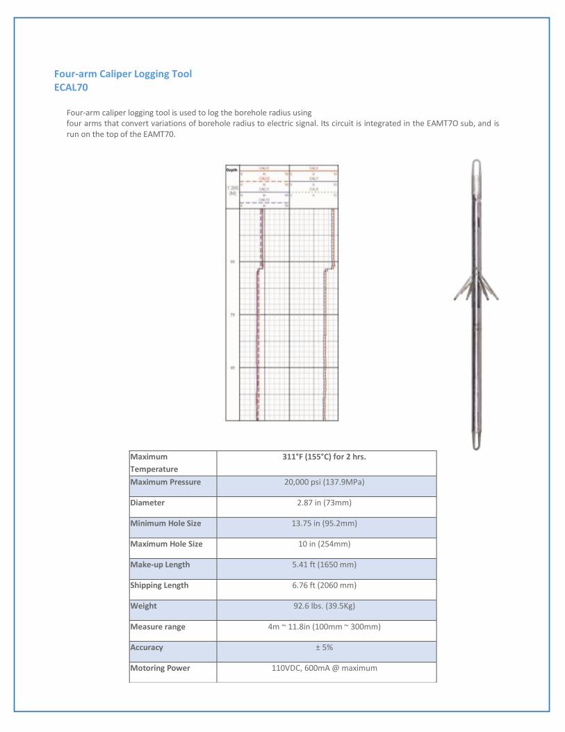
Four-arm Caliper Logging Tool ECAL70
Four-arm caliper logging tool is used to log the borehole radius using four arms that convert variations of borehole radius to electric signal. Its circuit is integrated in the EAMT7O sub, and is run on the top of the EAMT70.
Maximum
Temperature
311°F (155°C) for 2 hrs.
Maximum Pressure 20,000 psi (137.9MPa)
Diameter 2.87 in (73mm)
Minimum Hole Size 13.75 in (95.2mm)
Maximum Hole Size 10 in (254mm)
Make-up Length 5.41 ft (1650 mm)
Shipping Length 6.76 ft (2060 mm)
Weight 92.6 lbs. (39.5Kg)
Measure range 4m ~ 11.8in (100mm ~ 300mm)
Accuracy ± 5%
Motoring Power 110VDC, 600mA @ maximum

Temperature, Tension, Fluid Resistivity Sub ERMT70
The ERMT70 sub contains three types of transducers for measurement of cable head tension/compression force, borehole temperature, and mud resistivity. This tool must be used on top of the ER1T70 tool. Diameter: 2.87in (73mm)
Maximum temperature 311°F (155°C) for 2 hrs.
Maximum pressure 20,000 psi (137.9MPa)
Diameter
Minimum Hole Size: 3.75in (95.2mm)
Maximum Hole Size: N/A
Make-up Length: 3.61ft (1100mm)
Shipping Length 4.95 ft (1510mm)
Weight 55.1 lbs. (25 kg)
Maximum Logging Speed 100ft/min (30m/min)
Measurement Range
Cable head Tension 0 to 12,000 lbs. Tension
Borehole Temperature 2°F to 392°F (0°C to 200°C)
Mud Resistivity 0.01 Ω.m to 10 Ω.m
Accuracy
Cable head Tension ± 800 lbs. Tension ± 5% ± 800 lbs. Compression ± 5%
Borehole Temperature ±4°F ± 5% (2°C ± 5%)
Mud Resistivity 0.01 Ω.m ± 5%Mud Resistivity: ± 0.01 O -m ± 5%


Temperature] Tension/ Fluid Resistivity Sub ERMT
The ERMT is a 3-5/8" diameter sub containing three types of transducers for measurement of cable head tension/compression force, borehole temperature, and mud resistivity. This tool must be used on top of the ERTT tool.
Repeatability
Cable head Tension ± 100 lbs. Tension ± 100 lbs. Compression
Borehole Temperature 4°F(± 2°C)
Mud Resistivity ± 0.01 O -m ± 5%
Maximum Tensile
Force
37,000 lb.
Maximum
Compressive Force
174,000 lb.
Maximum
temperature
400°F (204°C) for 0.5hrs.; 300°F (150°C) for 3hrs.
Maximum pressure 20,000psi (137.9 Mpa)
Borehole diameter 4.5in. (114.5mm) ~ N.A.
Tool diameter 3.63in. (92mm)
Make-up Length 43.8in. (1 .1 1 m)
Shipping Length 60in. (1.52m)
Weight 80lb (36.3kg)
Measurement Range
Cable head Tension 0 ~ 12,000 lbs. Tension 0 ~ 10,000 lbs. Compression
Borehole
Temperature
32°F ~ 446°F (0°C ~ 230°C)
Mud Resistivity 0.01 ~ 10 Ω-m
Accuracy
Cable head Tension ±800 lbs. Tension ± 5% ± 800 lbs. Compression ± 5%
Differential Cable
head Tension
± 100 lbs. Tension ± 100 lbs. Compression
Borehole
Temperature
± 4°F ± 5% (± 2 °C ± 5%)
Mud Resistivity 0.01 Ω-m ±5%

Three Arm Caliper Logging Tool
Three Arm Caliper Logging Tool is used to log the borehole diameter through the three arms to drive the POT inside the tool, and transfer the change of borehole diameter to electric signal. In the ELIS logging system, the electric signal can be calculated to the digital borehole diameter with factors from the calibration process.
Maximum
Temperature
350°F (175°C) 2 hours
Maximum Pressure 20,305Psi (140MPa)
Diameter 4.4lin.(112mm)
Make-up length 7ft-6.6in.(2.3m)
Measurement Range 6in.(152.4mm) 10in.(406.4mm)
Measurement
Accuracy
0.41 in.
Power Requirement 180VAC@20mA 60Hz
Logging combination ERTT combination
Wireline Requirement 7 conductor cable
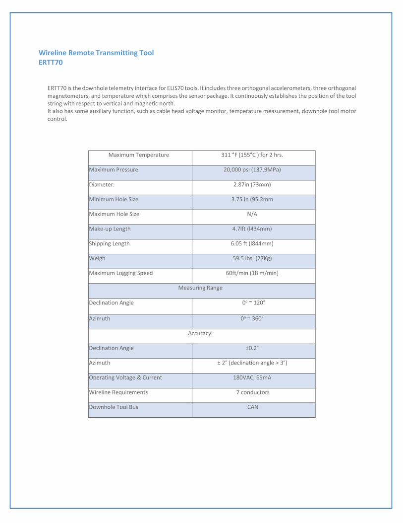
Wireline Remote Transmitting Tool ERTT70
ERTT70 is the downhole telemetry interface for ELIS70 tools. It includes three orthogonal accelerometers, three orthogonal magnetometers, and temperature which comprises the sensor package. It continuously establishes the position of the tool string with respect to vertical and magnetic north. It also has some auxiliary function, such as cable head voltage monitor, temperature measurement, downhole tool motor control.
Maximum Temperature 311 °F (155°C ) for 2 hrs.
Maximum Pressure 20,000 psi (137.9MPa)
Diameter: 2.87in (73mm)
Minimum Hole Size 3.75 in (95.2mm
Maximum Hole Size N/A
Make-up Length 4.7lft (l434mm)
Shipping Length 6.05 ft (l844mm)
Weigh 59.5 lbs. (27Kg)
Maximum Logging Speed 60ft/min (18 m/min)
Measuring Range
Declination Angle 0o ~ 120°
Azimuth 0o ~ 360°
Accuracy:
Declination Angle ±0.2°
Azimuth ± 2° (declination angle > 3°)
Operating Voltage & Current 180VAC, 65mA
Wireline Requirements 7 conductors
Downhole Tool Bus CAN


Wireline Remote Transmitting Tool ERTT
This tool is a data transmission instrument supporting EDIB (ELIS Downhole Instrument Bus) protocol. Its main function is to complete data communication between downhole tool string and surface system. It also has some auxiliary functions, such as cable-head voltage monitor, downhole tool motor control and deal with some analog quantity such as SP, CCL, Cable Head Tension, temperature and Mud Resistance. All EDIB bus tools can be connected to the bottom of ERTT.
Feature:
Support downhole tools bus protocol EDIB for ELIS system
high transmission rate Three up-hole data transmission channels
low error rate
Maximum Temperature 400°F (204°C) for 10hrs
Maximum Pressure 20,000 psi (137.9Mpa)
Diameter 3.63in. (92mm)
Length 6ft.-3in. (1 .895m)
Weight 143.5lb (65kg)
Wireline Requirement 7 conductor cable
Operating Power 180VAC @ 100mA, 60Hz
Coding Mode Manchester Code
Cable Transmission rates 230Kpbs
Minimum borehole diameter 4.00 in. (101 mm)
Maximum well-logging speed 200 ft/min (60 m/min)
Cable Head Tension
Measurement range
-53379 N (-12,000 lbf)
(-5436 kgf) ~ +53779 N (+12,000 lbf) (+5346 kgf)
Accuracy 13.34 N (3 lbf) (1.359 kgf)
Downhole temperature
Measurement range
-55°C (-67°F) to +245°C (473°F)
Accuracy: 0.12°C (0.216°F)
Downhole SP
Measurement range
-1300 mV to +1300 mV
Accuracy 0.15 mV
Mud Resistance
Measurement range
0.01 ohm-m to 10 ohm-m
Instrument Working Voltage and current 180 VAC, 100-125 mA