
AD-A142 603 ANNUAL TECHNICAL SYMPOSIUM 21ST THE ENGINEERING CHALLENGE ... · ad-a142 603 annual...
43
AD-A142 603 ANNUAL TECHNICAL SYMPOSIUM 21ST THE ENGINEERING CHALLENGE OF A GROWINO .U) ASSOCIATION OF SCIENTISTS AND ENGINEERS OF THE NAVAL SEA SYST S KCHUNET AL UNC' ASSIFED 1984 FG10 L [END t84
Transcript of AD-A142 603 ANNUAL TECHNICAL SYMPOSIUM 21ST THE ENGINEERING CHALLENGE ... · ad-a142 603 annual...
AD-A142 603 ANNUAL TECHNICAL SYMPOSIUM 21ST THE ENGINEERINGCHALLENGE OF A GROWINO .U) ASSOCIATION OF SCIENTISTS
AND ENGINEERS OF THE NAVAL SEA SYST S KCHUNET AL
UNC' ASSIFED 1984 FG10 L
[ENDt84
1.8
i = 6
MICRCOP RfLa O __ S ____ f

AD-A 142 603 -
21 ANNUALTECHNICAL A S
SYMPOSIUM
1984
W -4- - "THE ENGINEERING CHALLENGE OF A GROWING NAVY"
C6-
C-: RETROFITTING OF BULBOUS BOWS ON U.S. NAVYk-H AUXILIARY AND AMPHIBIOUS * W"F P f€
Stephen K. Chun
CJeffrey J. HoughA len H. EngleSiu C. Fung
ASSOCIATION OF SCIENTISTS AND ENGINEERS OF THE NAVAL SEA SYSTEMS COMMAND * DEPARTMENT OF THE NAVY * WASHIN ON [1 C 20362
Retrofitting of Bulbous Bows on U.S. Navy Auxiliaryand Amphibious Warfare Ships for Fuel Savings
Stephen K. Chun Allen H. EngleNaval Architect Naval Architect
Hull Form and Hydrodynamics Hull Form and HydrodynamicsPerformance Division Performance Division
Naval Sea Systems Command Naval Sea Systems Command
Jeffrey J. HoughSiu Fung Naval Architect
Naval Architect Hull Form and HydrodynamicsDesigners & Planners, Inc. Performance Division
Naval Sea Systems Command
Approved for Public ReleaseDistribution Unlimited
The view exprc3sed herein are the personal opinionsof the authors and are not necessarily the official
views of the Department of Defense or ofthe Department of the Navy
TABLE OF CONTENTS
Subject Page
List of Tables ....................................................... ii
Notation ............................................................ iii
Abstract............................................................. iv
Introduction.......................................................... 1
Selection of Candidate Ships..........................................2
Cost-Benefit Analysis-Procedure.......................................9
Bulb Retrofit Procedure.............................................. 19
Bow Bulb Design Methodology .......................................... 22
Conclusions.......................................................... 25
References........................................................... 27
Appendix A
Definition of Bulb Parameters.................................... 28
Figures
1. Shaft Horsepower Ratio for an Amphibious Warfare Type Ship .. 31
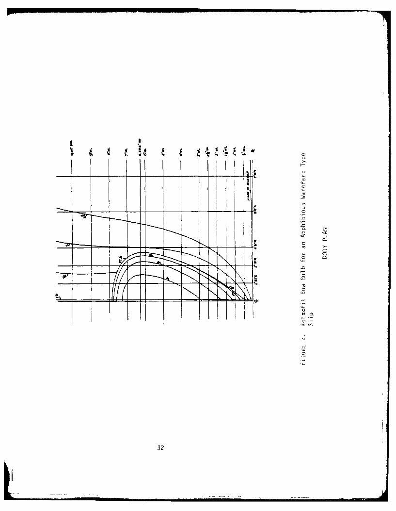
2. Body Plan for a Retrofit Bow Bulb for
an Amphibious Warfare Type Ship................................32
3. Half Breadth Plan for a Retrofit Bow Bulb for
an Amphibious Warfare Type Ship................................33
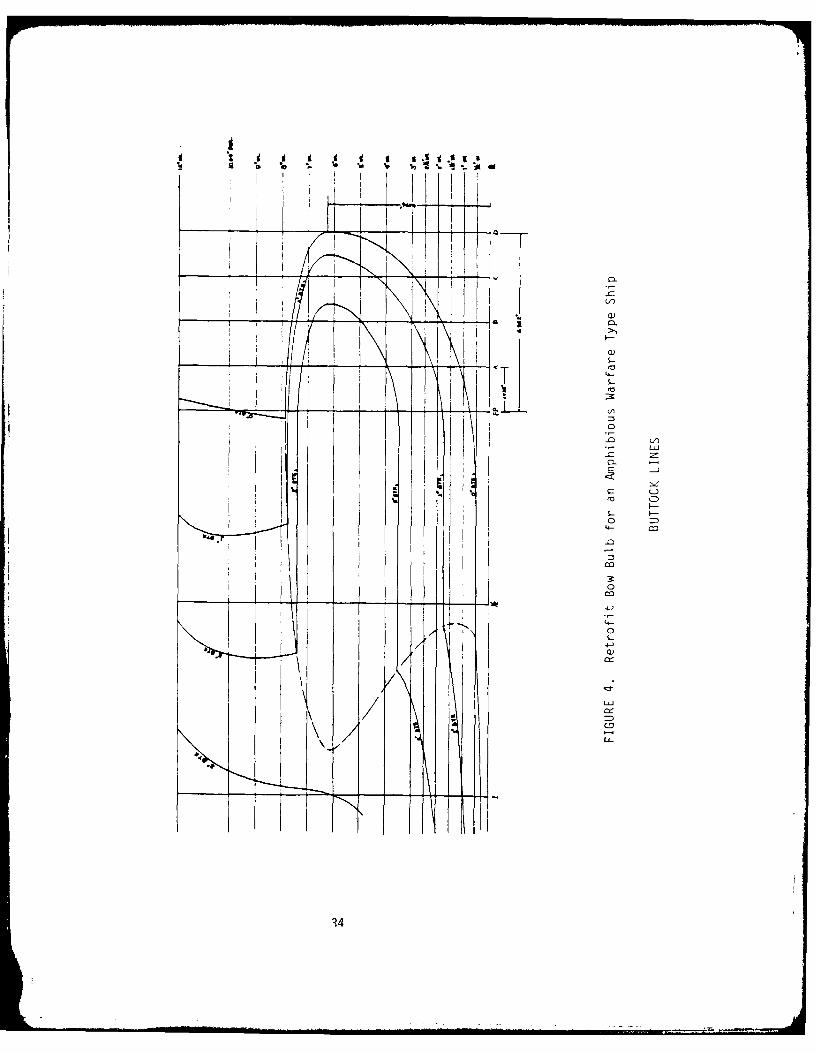
4. Buttock Lines Plane for a Retrofit Bow Bulb for
an Amphibious Warfare Type Ship ................................34
31,:T
--r
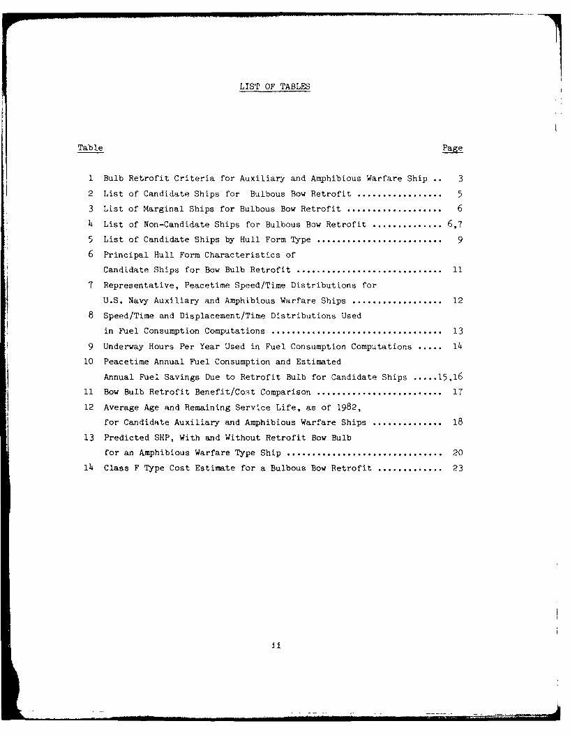
LIST OF TABLES
Table Page
1 Bulb Retrofit Criteria for Auxiliary and Amphibious Warfare Ship 3
2 List of Candidate Ships for Bulbous Bow Retrofit ................... 5
3 List of Marginal Ships for Bulbous Bow Retrofit ..................... 6
4 List of Non-Candidate Ships for Bulbous Bow Retrofit .............. 6,7
5 List of Candidate Ships by Hull Form Type ............................ 9
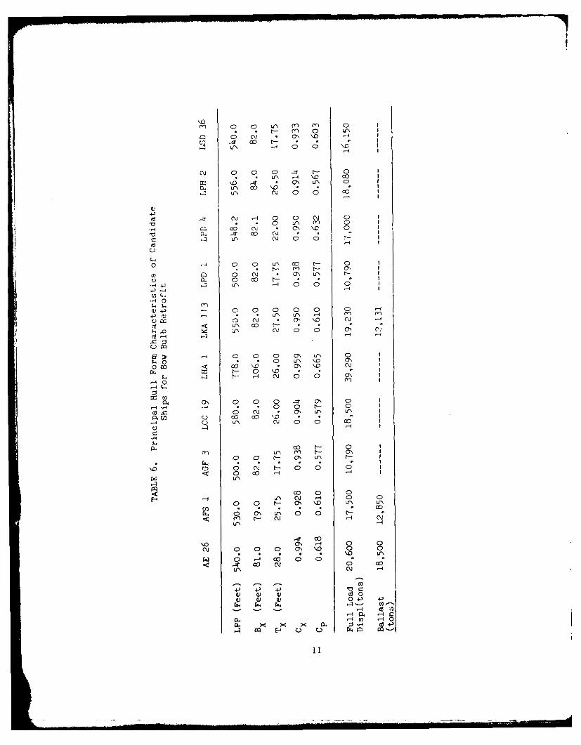
6 Principal Hull Form Characteristics of
Candidate Ships for Bow Bulb Retrofit ............................... 11
7 Representative, Peacetime Speed/Time Distributions for
U.S. Navy Auxiliary and Amphibious Warfare Ships ................... 12
8 Speed/Time and Displacement/Time Distributions Used
in Fuel Consumption Computations .................................... 13
9 Underway Hours Per Year Used in Fuel Consumption Computations ..... 14
10 Peacetime Annual Fuel Consumption and Estimated
Annual Fuel Savings Due to Retrofit Bulb for Candidate Ships ..... 15,16
11 Bow Bulb Retrofit Benefit/Cost Comparison ........................... 17
12 Average Age and Remaining Service Life, as of 1982,
for Candidate Auxiliary and Amphibious Warfare Ships .............. 18
13 Predicted SHP, With and Without Retrofit Bow Bulb
for an Amphibious Warfare Type Ship ................................. 20
14 Class F Type Cost Estimate for a Bulbous Bow Retrofit .............. 23
L ....i

NOTATION
ABL Area of Projection of' bulb on ship's centerline plane
ABT Transverse cross-sectional area of bulb at forward perpendicular
AIMS Midship section area of ship to design waterline
BB Maximum breadth of bulb area
B Maximum breadth of shipxBMS Breadth of ship at midship, at design waterline
CABL Bulb lateral parameter
C Bulb cross-section parameterABT
C Block o-efficientB
CBB Bulb breadth parameter
C Bulb length parameterLPR
C Prismatic coefficient
CVPR Bulb volumetric parameter
CX Maximum sectional area coefficient
C ZB Bulb depth parameter
Lpp Length between perpendiculars
LPR Protruding length of bulb
VPR Volume of protruding bulb
VWL Displaced volume at design waterline
ZB Height of foremost point of the bulbBr
iii

ABSTRACT
To meet energy conservation goals of the Navy, its attention has been
focused on ways to reduce individual ship total resistance and powering
requirements. One possible method of improving ship powering characteristics
is by modifying existing individual ship hulls with the addition of bulbous
bows. This paper will identify the merits of retrofitting bow bulbs on
selected U.S. Navy auxiliary and amphibious warfare ships. A procedure for
performing a cost/benefit analysis will be shown for candidate ship classes.
An example of this technique for an amphibious warfare ship will also be
provided. A brief discussion of future methods to be used for bulbous bow
design such as application of systematic model test data and numerical
hydrodynamic techniques will be given.,
iv
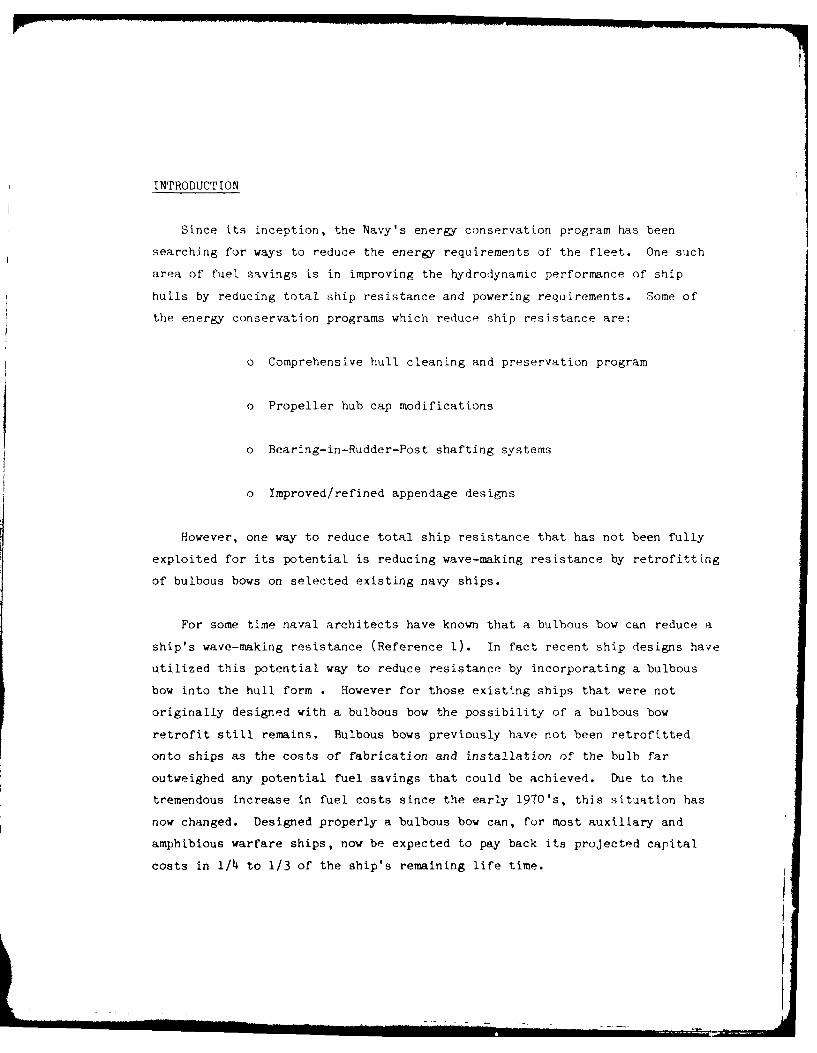
INTRODUCTION
Since its inception, the Navy's energy conservation program has been
searching for ways to reduce the energy requirements of the fleet. One such
area of fuel savings is in improving the hydrodynamic performance of ship
hulls by reducing total ship resistance and powering requirements. Some of
the energy conservation programs which reduce ship resistance are:
o Comprehensive hull cleaning and preservation program
o Propeller hub cap modifications
o Bearing-in-Rudder-Post shafting systems
o Improved/refined appendage designs
However, one way to reduce total ship resistance that has not been fully
exploited for its potential is reducing wave-making resistance by retrofitting
of bulbous bows on selected existing navy ships.
For some time naval architects have known that a bulbous bow can reduce a
ship's wave-making resistance (Reference 1). In fact recent ship designs have
utilized this potential way to reduce resistance by incorporating a bulbous
bow into the hull form . However for those existing ships that were not
originally designed with a bulbous bow the possibility of a bulbous bow
retrofit still remains. Bulbous bows previously have not been retrofitted
onto ships as the costs of fabrication and installation of the bulb far
outweighed any potential fuel savings that could be achieved. Due to the
tremendous increase in fuel costs since the early 1970's, this situation has
now changed. Designed properly a bulbous bow can, for most auxiliary and
amphibious warfare ships, now be expected to pay back its projected capital
costs in i/h to 1/3 of the ship's remaining life time.

Procedures are now available which allow the naval architect to select
bulb parameters without the extensive and time-consuming model test program
that would normally be required. Once a bulb is designed a model test program
coupled with this procedure would then be used only in an effort to verify the
empirically based predictions. If other ship impact issues in addition to
hydrodynamic concerns are satisfactorily resolved and the bulb shows potential
for significant fuel savings during the remaining lifetime of the ship, a
retrofit should receive serious consideration.
SELECTION OF CANDIDATE SHIPS
Several factors must be considered before one can determine the
feasibility of retrofitting bulbous bows on ships. For the U.S. Navy the ship
types which are considered most likely to realize a savings in fuel are
certain auxiliary and amphibious warfare ships. This is because their hull
form shapes and speed-length ratios are in the ideal range where bulbous bows
have the maximum potential to reduce wave-making resistance. Their hulls also
do not have bow sonar domes which would preclude bulb installation.
Furthermore, the experience of commercial shipping with bulbous bows can be
directly applied due to the similiarity of auxiliary and amphibious warfare
ship hulls to merchant hull forms.
Now that it has been determined which ship types may benefit from a
retrofit bulb, it becomes necessary to address the practicality of a bulb
installation on each ship class. Concerns such as physical interference
between a bulb and other objects such as ships anchors or bow thrusters must
be examined. Review of the anchor arrangements of a ship might place
constraints on the overall dimensions )f the bulb while the cost required to
fair the bulb plating into existing plating at the thruster tunnel openings
might require the removal of these ships from consideration. Mission
requirements mist also be addressed; for example the requirement for LSTs to
beach themselves and the infrequent time-at-sea underway of tenders would
preclude either of these type ships from consideration.
2
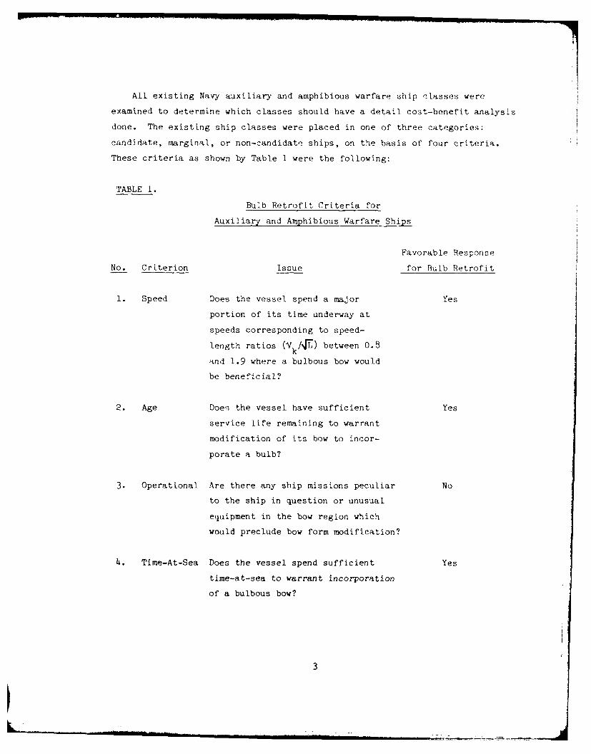
All existing Navy auxiliary and amphibious warfare ship classes were
examined to determine which classes should have a detail cost-benefit analysis
done. The existing ship classes were placed in one of three categories:
candidate, marginal, or non-candidato ships, on the basis of four criteria.
These criteria as shown by Table 1 were the following:
TABLE 1.
Bulb Retrofit Criteria for
Auxiliary and Amphibious Warfare Ships
Favorable Response
No. Criterion Issue for Bulb Retrofit
1. Speed Does the vessel spend a major Yes
portion of its time underway at
speeds corresponding to speed-
length ratios (kV kAV) between 0.8
and 1.9 where a bulbous bow would
be beneficial?
2. Age Does the vessel have sufficient Yes
service life remaining to warrant
modification of its bow to incor-
porate a bulb?
3. Operational Are there any ship missions peculiar No
to the ship in question or unusual
equipment in the bow region which
would preclude bow form modification?
4. Time-At-Sea Does the vessel spend sufficient Yes
time-at-sea to warrant incorporation
of a bulbous bow?
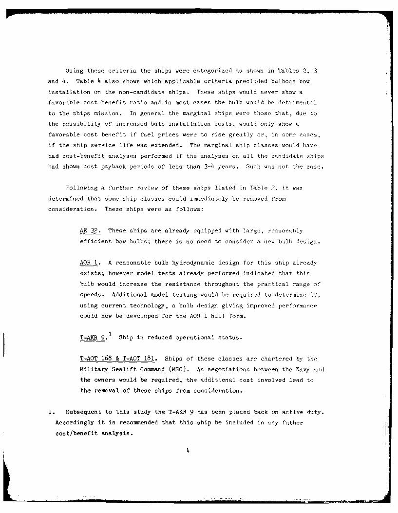
Using these criteria the ships were categorized as shown in Tables 2, 3
and 4. Table 4 also shows which applicable criteria precluded bulbous bow
installation on the non-candidate ships. These ships would never show a
favorable cost-benefit ratio and in most cases the bulb would be detrimental
to the ships mission. In general the marginal ships were those that, due to
the possibility of increased bulb installation costs, would only show a
favorable cost benefit if fuel prices were to rise greatly or, in some cases,
if the ship service life was extended. The marginal ship classes would have
had cost-benefit analyses performed if the analyses on all the candidate ships
had shown cost payback periods of less than 3-4 years. Such was not the case.
Following a further review of these ships listed in Table 2, it was
determined that some ship classes could immediately be removed from
consideration. These ships were as follows:
AE 32. These ships are already equipped with large, reasonably
efficient bow bulbs; there is no need to consider a new bilb design.
AOR 1. A reasonable bulb hydrodynamic design for this ship already
exists; however model tests already performed indicated that this
bulb would increase the resistance throughout the practical range of
speeds. Additional model testing would be required to determine if,
using current technology, a bulb design giving improved performance
could now be developed for the AOR I hull form.
T-AKR 9.1 Ship in reduced operational status.
T-AOT 168 & T-AOT 181. Ships of these classes are chartered by the
Military Sealift Command (MSC). As negotiations between the Navy and
the owners would be required, the additional cost involved lead to
the removal of these ships from consideration.
1. Subsequent to this study the T-AKR 9 has been placed back on active duty.
Accordingly it is recommended that this ship be included in any futher
cost/benefit analysis.
4
I
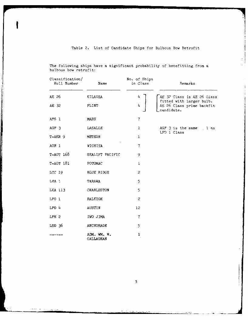
Table 2. List of Candidate Ships for Bulbous Bow Retrofit
The following ships have a significant probability of benefitting from abulbous bow retrofit:
Classification/ No. of ShipsHull Number Name in Class Remarks
AE 26 KILAUEA FAE 32 Class is AE 26 Classfitted with larger bulb.
AE 32 FLINT 4 AE 26 Class prime backfitLcandidate.
AFS 1 MARS 7
AGF 3 LASALLE 1 AGF 3 is the same 1 asLPD 1 Class
T-AKR 9 METEOR 1
AOR 1 WICHITA 7
T-AOT 168 SEALIFT PACIFIC 9
T-AOT 181 POTOMAC 1
LCC 19 BLUE RIDGE 2
LHA 1 TARAWA 5
LKA 113 CHARLESTON 5
LPD 1 RALEIGH 2
LPD 4 AUSTIN 12
LPH 2 IWO JIMA 7
LSD 36 ANCHORAGE 5
ADM. WM. M. 1CALLAGHAN
5
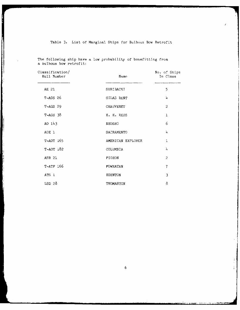
Table 3. List of Marginal Ships for Bulbous Bow Retrofit
The following ship have a low probability of benefitting froma bulbous bow retrofit:
Classification/ No. of ShipsHull Number Name In Class
AE 21 SURIBACHI 5
T-AGS 26 SILAS BENT 4
T-AGS 29 CHAUVENEr 2
T-AGS 38 H. H. HESS I
AO 143 NEOSHO 6
AOE I SACRAMENTO 4
T-AOT 165 AMERICAN EXPLORER 1
T-AOT 182 COLUMBIA 4
ASR 21 PIGEON 2
T-ATF 166 POWHATAN 7
ATS I EDENTON 3
LSD 28 THOMASTON 8
6
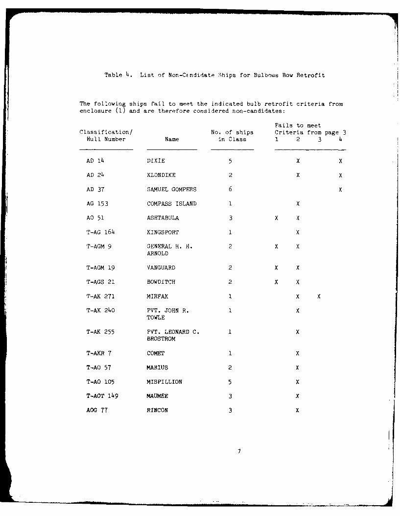
Table 4. List of Non-Candidate 3hips for Bulbous Bow Retrofit
The following ships fail to meet the indicated bulb retrofit criteria fromenclosure (1) and are therefore considered non-candidates:
Fails to meetClassification/ No. of ships Criteria from page 3
Hull Number Name in Class 1 2 3 4
AD l4 DIXIE 5 X X
AD 24 KLONDIKE 2 X X
AD 37 SAMUEL GOMPERS 6 x
AG 153 COMPASS ISLAND 1 X
AO 51 ASHTABULA 3 X X
T-AG 164 KINGSPORT 1 X
T-AGM 9 GENERAL H. H. 2 X XARNOLD
T-AGM 19 VANGUARD 2 X X
T-AGS 21 BOWDITCH 2 X X
T-AK 271 MIRFAK 1 X X
T-AK 240 PVT. JOHN R. 1 XTOWLE
T-AK 255 PVT. LEONARD C. 1 XBROSTROM
T-AKR 7 COMET 1 X
T-AO 57 MARIUS 2 X
T-AO 105 MISPILLION 5 X
T-AOT 149 MAUMEE 3 X
AOG 77 RINCON 3 X
7
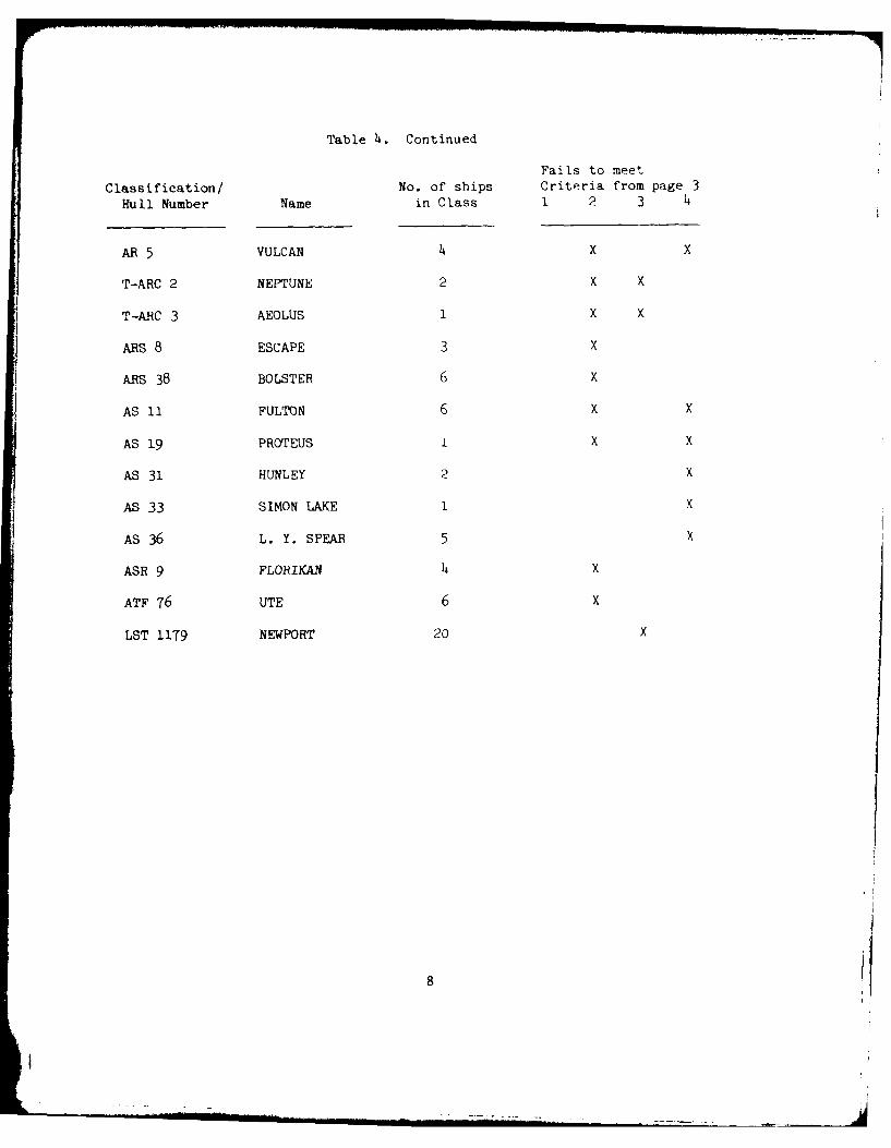
Table 4. Continued
Fails to meet
Classification/ No. of ships Criteria from page 3
Hull Number Name in Class 1 2 3 4
AR 5 VULCAN 4 X X
T-ARC 2 NEPTUNE 2 X X
T-ARC 3 AEOLUS 1 X X
ARS 8 ESCAPE 3 X
ARS 38 BOLSTER 6 x
AS 11 FULTON 6 x x
AS 19 PROTEUS I X X
AS 31 HUNLEY 2 X
AS 33 SIMON LAKE I X
AS 36 L. Y. SPEAR 5 X
ASR 9 FLORIKAN h x
ATF 76 UTE 6 x
LST 1179 NEWPORT 20 X
81
. .. . - L
The remaining candidate ship classes could be further divided into
categories as shown by Table 5.
TABLE 5.
Auxiliary or Cargo-Ship '"et-Well"-Ship
Type Hull Forms Type Hull Forms
AE 26 AGF 3
AFS 1 LHA 1
LCC 19 LPD 1
LKA 113 LPD 4
LPH 2 LSD 36
For the ships remaining a cost-benefit analysis is required to determine
the feasibility of a bulbous bow retrofit.
COST-BENEFIT ANALYSIS-PROCEDURE
The primary motive for a bulbous bow retrofit is the potential for fuel
savings. While the bulb's effect on other hydrodynamic performance concerns
such as maneuvering and seakeeping must be addressed, review of previous ship
designs with bulbous bows suggest that their effects are not of enough
significance in themselves to affect a decision to retrofit a bulb. Hence,
fuel conservation versus bulb fabrication and installation costs becomes the
basis for deciding on a retrofit.
In order to carry out the bow bulb retrofit benefit/cost study, a
standardized procedure was developed in Reference (2) and shown for candidate
ships (see Tables 6-12); this procedure can be summarized as follows:
o Calm water speed versus power data was assembled for the various
ships. In addition, estimates of the effects of a moderately-sized,
non-complex (i.e., suitable for retrofit) bow bulb on the calm water
powering performance of each ship were developed.
9
o Speed-time distributions were assembled, and estimates of the annual
underway time and percent times at full load and at ballast drafts
were developed, in order to synthesize an approximate "mission" for
each ship.
o Fuel consumption versus horsepower data were developed for each ship.
o Using the above-described data, annual fuel consumption estimates
were developed for each ship in its current "no-bulb" configuration
and with a bow bulb. The differences in the fuel consumption
estimates represented, for each ship, the estimated annual fuel
consumption savings due to retrofit of a bow bulb.
o Preliminary lines drawings, structural sketches, and weight estimates
were developed for representative retrofit-type bow bulbs.
o An estimate of the cost of fabricating and installing a
representative retrofit-type bow bulb was developed.
o The estimated fuel consumption savings due to installation of a
retrofit-type bow bulb were compared with the estimated costs of
fabricating and installing such a bulb.
Assuming that the average price for fuel is $80 per barrel, the estimated
annual savings in fuel cost has been calculated from the data in Table 11 and
is shown for candidate ships in Table 12. It can then clearly be seen that
the projected average savings will range from $46,000 to $231,000 annually.
One must note that all figures quoted in this report are based upon
currently available information concerning speed/time profiles, hours underway
per year as well as current fuel prices. Therefore a change in any one of
these variables obviously could alter the timeframe required to recover
initial capital investments and hence, the feasibility of retrofitting a
bulbous bow on a particular ship.
10
r~ 0 C) \ C1 '
0 C C'J * V7 \0 'J) --r a t-
-4 I
oj 0 0) 0 --1 t- 0* N -A \Do aj
U-\ CO \0 * ~ Ir
UN\ (N 0 0 co
4--4
Cc.- C\J -4 0 0 (NJ 021 '0 * * : U-\ mY 0
C" co NN * N fl 0
-I U\ N 0 0
C)
0 0 0 UN, co ~ 0
cn UN U '1 -\ N
o0 co t- *
.144- U.N-4 00\
-40
CD4- 0 0D 0 0 0 -44-) *) UN LU.N m~ m'
0 N' N f N
1. (NJ 0 ON (Njc-A
C) 0 0 CIN u.N 0
0CO 'UO * N \0 (NJ
rCL t- 0 '-0 *
I.. - N4 C\J 0 O
-4 4-
ON\ 0 0 0 -Z CN 0-4 0 0 - C I
cdA,0 CU N . U
") M C CC) \fl*T4C N IN 0 0 co
oo t -
I- I r
cx C CO C- 0 1
'~C) 0 (J - 0 00 CC) 1-4 '-4
co 0 0-4UN (\j 1-4 0 0
0r 0 r-40UN U
CL 0 N C\ 0 0 0-
~ - (NJ '-4 (N
VN ON -4 0
(J 0 0) 0) ON 4. 0 0r rx r., 0
-A -4 -4 0 0
-- A U) -l 0
4-. 4- 4-'a 4 ,
co E-44
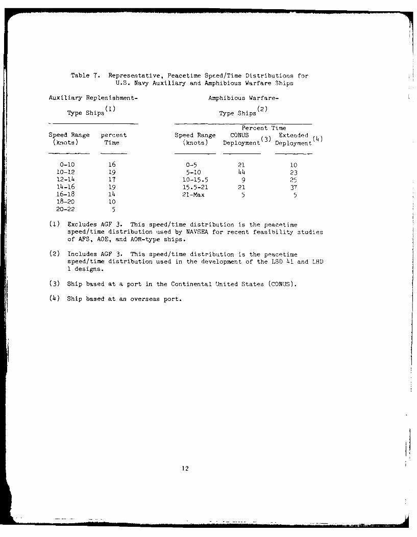
Table 7. Representative, Peacetime Speed/Time Distributions forU.S. Navy Auxiliary and Amphibious Warfare Ships
Auxiliary Replenishment- Amphibious Warfare-
Type Ships Type Ships(2)
Percent TimeSpeed Range percent Speed Range CONUS (3) Extended
(knots) Time (knots) Deployment Deployment
0-10 16 0-5 21 1010-12 19 5-10 44 2312-14 17 10-15.5 9 2514-16 19 15.5-21 21 3716-18 14 21-Max 5 518-20 1020-22 5
(1) Excludes AGF 3. This speed/time distribution is the peacetimespeed/time distribution used by NAVSEA for recent feasibility studiesof AFS, AOE, and AOR-type ships.
(2) Includes AGF 3. This speed/time distribution is the peacetimespeed/time distribution used in the development of the LSD 41 and LHDI designs.
(3) Ship based at a port in the Continental United States (CONUS).
(4) Ship based at an overseas port.
12
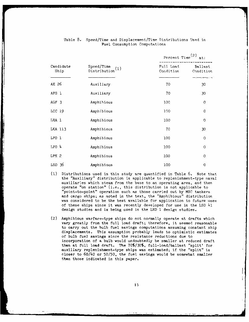
Table 8. Speed/Time and Displacement/Time Distributions Used inFuel Consumption Computations
Percent Time (2) at:
Candidate Speed/Time Full Load BallastShip Distribution Condition Condition
AE 26 Auxiliary 70 30
AFS 1 Auxiliary 70 30
AGF 3 Amphibious 100 0
LCC 19 Amphibious 100 0
LHA 1 Amphibious 100 0
LKA 113 Amphibious 70 30
LPD 1 Amphibious 100 0
LPD 4 Amphibious 100 0
LPH 2 Amphibious 100 0
LSD 36 Amphibious 100 0
(1) Distributions used in this study are quantified in Table 6. Note thatthe "Auxiliary" distribution is applicable to replenishment-type navalauxiliaries which steam from the base to an operating area, and thenoperate "on station" (i.e., this distribution is not applicable to"point-to-point" operation such as those carried out by MSC tankersand cargo ships; as noted in the text, the "Amphibious" distributionwas considered to be the best available for application to future usesof these ships since it was recently developed for use in the LSD 41design studies and is being used in the LHD 1 design studies.
(2) Amphibious warfare-type ships do not normally operate at drafts whichvary greatly from the full load draft; therefore, it seemed reasonableto carry out the bulb fuel savings computations assuming constant shipdisplacements. This assumption probably leads to optimistic estimatesof bulb fuel savings since the resistance reductions due toincorporation of a bulb would undoubtedly be smaller at reduced draftthan at full load draft. The 70%/30%, full-load/ballast "split' forauxiliary replenishment-type ships was estimated; if the "split" iscloser to 60/40 or 50/50, the fuel savings would be somewhat smallerthan those indicated in this paper.
13
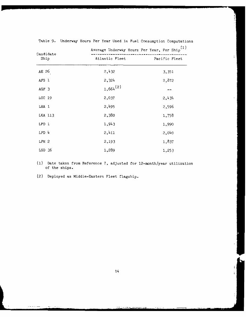
Table 9. Underway Hours Per Year Used in Fuel Consumption Computations
Average Underway Hours Per Year, Per Ship(l)
CandidateShip Atlantic Fleet Pacific Fleet
AE 26 2, 4 3 2 3,351
AFS 1 2,324 2,872
AGF 3 1,664(2) --
LCC 19 2,037 2,434
LHA 1 2,495 2,596
LKA 113 2,380 1,758
LPD 1 1,943 1,990
LPD 4 2,411 2,040
LPH 2 2,193 1,837
LSD 36 1,289 1,253
(1) Date taken from Reference 7, adjusted for 12-month/year utilizationof the ships.
(2) Deployed as Middle-Eastern Fleet flagship.
14
\.D tfl-- r'1Q 0\ ~- 00c ( J t-- E-- 0\ t- 0 0 '110t4. *-. tl- I--ON (Nj -4 -~4 m 00a 0 Lr\. __r u\ ( L- \.
cc) Q) V
1. 10 4 -4 ~-4 rl \ - l -4 -4 -4
>0 .
WOO () 0000 0 0 0 0 0 0 0 0
ONV 10 _ - It- A C,-- )) - Y 7 -,Cju\CQ) P~~~~~4-w ()_r- O - C4 - 3 t- -- r _ l Cjo ~
El-\ : j)-T \C - . - 0 a\C : -
4-) '
4- w P.. ~ r\u\ \D \O\, \T zr-Tt 0\C - 4- VC) \D 0 C 1 10 m()0 3 oa oc j .
4 -)- ) 11- 1- Y 4 ~ ~ jN CjN N Cjr4rI CjC!(Ir
CC
s o 4-) '
=f -4 00 14,
0 0 00
0) 04 r- -4 x4 X 4 4
z 0r-' 04-0 VV
0 V 0 0 0Q)9 0.- 'A -4-0
.-4 V _4 V 00C W a) 0
,0 -V 1-4 '* ~ r IS, 10 p4 X 0 X 00
0- 4 V V) (V 0 C 0
Q) 0) R 0 0i 0) 0 ) 0W1-4 - *H> "-4 -- * 4 *H 4
04- -H .0. .0. .0
(1) ) ED p W 4 p En n E U
: 0 0 0 00 0 0
Ca Cd - - 4 f -
.4) -4O rf t1 4-4 .-4 ma0~ C\
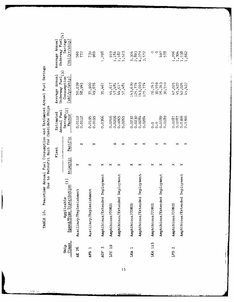
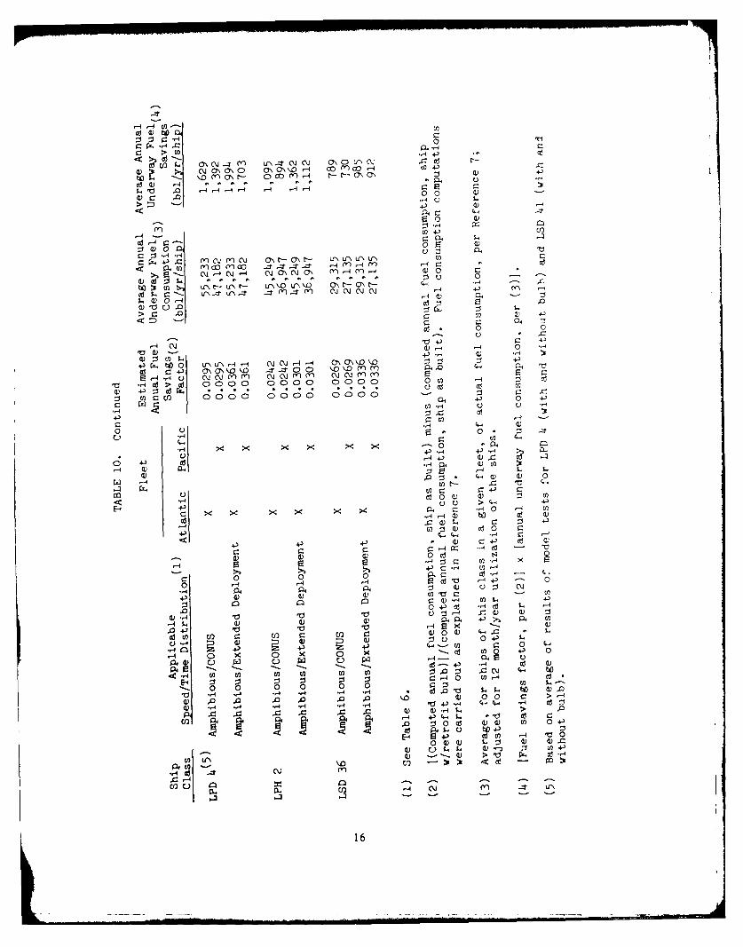
UC) CL 0 .d4 ..4
000-m -4 'c: -
15
,-4,4 w--
-4 -1 .- 0-
0 0
r
4-3~4- m lmN O - 1 - r u ' r
044 m- cc~ (-. co _r-r - M -qMC
15-. C\j r-4 C\14 cja C Ja 04C0\ (y) 0 C -
0). p ... 0 0
5a) 0 -4P .-
Cd'C,
44-r-q5 '-4d r4
',a 4) -H-
0 4-
r - 4-) 0 \\0 -r-r . f r
4- J E -. n ;: -.0n a, cn-004-'-
C U2-
0 00
4 En0.~
0-. 0- T1 ' () :5 U
161 .
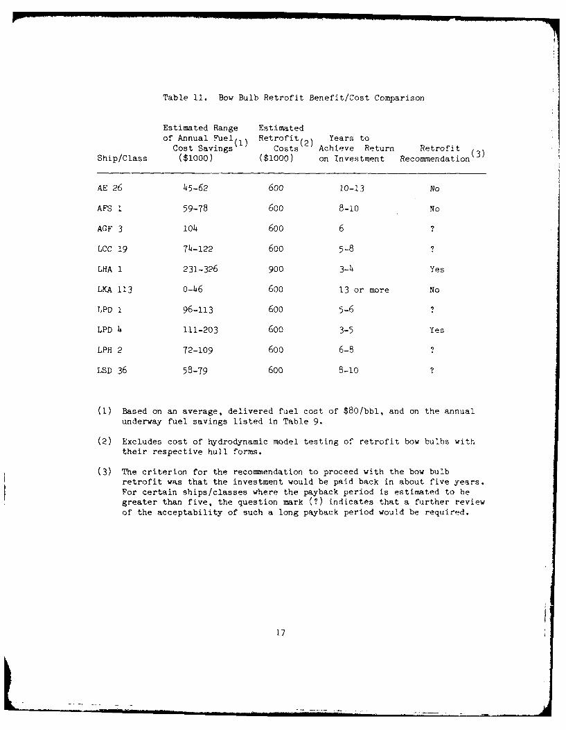
Table 11. Bow Bulb Retrofit Benefit/Cost Comparison
Estimated Range Estimatedof Annual Fuel(1 ) Retrofit(2 ) Years to
Cost Savings Costs Achieve Return RetrofitShip/Class ($1000) ($1000) on Investment Recommendation (3 )
AE 26 45-62 600 10-13 No
AFS 1 59-78 600 8-10 No
AGF 3 104 600 6 ?
LCC 19 74-122 600 5-8 ?
LHA 1 231-326 900 3-4 Yes
LKA 113 0-46 600 13 or more No
LPD 1 96-113 600 5-6 ?
LPD 4 111-203 600 3-5 Yes
LPH 2 72-109 600 6-8 ?
LSD 36 58-79 600 8-10 ?
(1) Based on an average, delivered fuel cost of $80/bbl, and on the annualunderway fuel savings listed in Table 9.
(2) Excludes cost of hydrodynamic model testing of retrofit bow bulbs withtheir respective hull forms.
(3) The criterion for the recommendation to proceed with the bow bulbretrofit was that the investment would be paid back in about five years.For certain ships/classes where the payback period is estimated to begreater than five, the question mark (?) indicates that a further reviewof the acceptability of such a long payback period would be required.
17
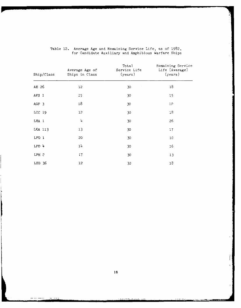
Table 12. Average Age and Remaining Service Life, as of 1982,for Candidate Auxiliary and Amphibious Warfare Ships
Total Remaining ServiceAverage Age of Service Life Life (Average)
Ship/Class Ships in Class (years) (years)
AE 26 12 30 18
AFS 1 15 30 15
AGF 3 18 30 12
LCC 19 12 30 18
LHA 1 4 30 26
LKA 113 13 30 17
LPD 1 20 30 10
LPD 4 14 30 16
LPH 2 17 30 13
LSD 36 12 30 18
18
However based upon the currciitly available infornition contained hr.-in,
the ships most likely to benefit from sivh a program are th, ;A I., LPD 4, LPP
1, AGF 3, and LCC 19 class ships (A suggested way to retrfi t a hull with a
bulbous bow as well as the associated costs involved will be discussed in
detail later in the p.per).
Two major points also fall out of this procedure (see Tables 7-11).
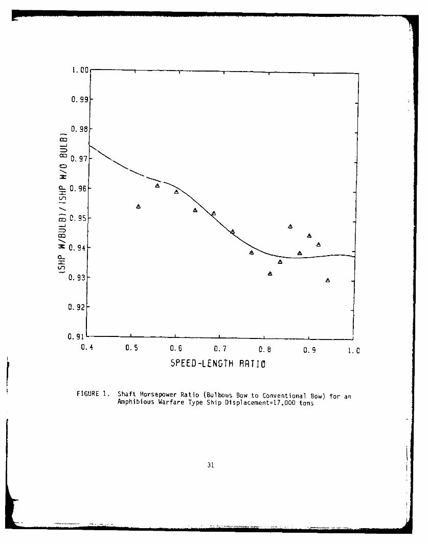
First is that the maximum fuel savings for a bulb occur at design speed and
will decrease in effectiveness as ship's speed decreases (see Table 13 and
Figure 1). This is explained by the fact that at low speeds frictional
resistance is the predominant portion of a ship's total resistance. Thus at
slow speeds a bulb's ability to reduce wave-making resistance becomes small.
A second point is that due to their operating profile, two-draft ships
(i.e., those ships that would operate part-time at a full load draft and
part-time at a ballast condition draft) are not appropriate candidates for
bulbous bow retrofits. This result is indicated by studies that show when
bulbs are designed for a deep draft condition they will perform poorly at a
ballast condition. As shown by Table 11 the annual potential fuel savings
will be, at best, half that for a single-draft ship. Accordingly, from an
economic standpoint the time required to recover the initial capital costs for
design, construction, and maintenance is so great one cannot justify
retrofitting bow bulbs on two-draft ships. Thus we have removed these ships
from further cosideration.
Therefore, one may consider the amphibious warfare type ship to benefit
the greatest by the retrofitting of a bulbous bow. What follows is an example
of this procedure for an amphibious warfare type ship.
BULB RETROFIT PROCEDURE
To meet projected fuel savings a bulb that is to be retrofitted will
require a detailed design effort. Once candidate bulbs are designed model
tests will be required to verify the optimum bulb configuration and upon the
19
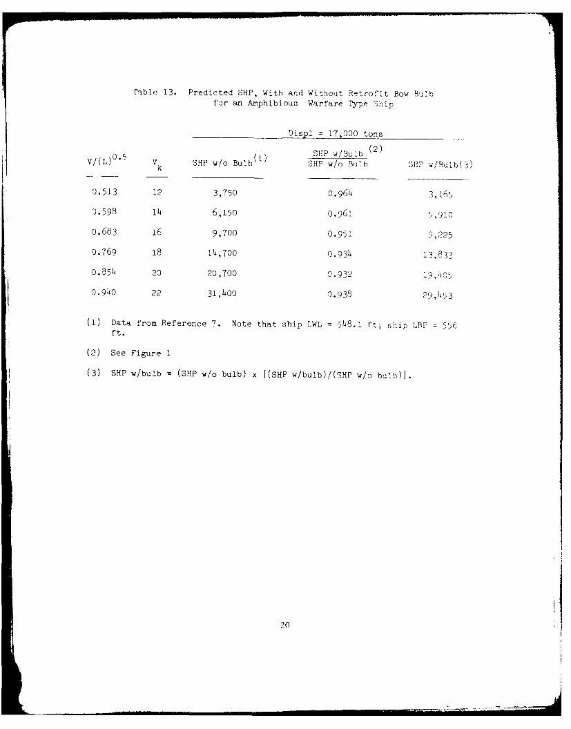
Table 13. Predicted SHP, With and Without Retrofit Bow Bulbfor an Amphibious Warfare Type Ship
Displ = 17,000 tons
0.5 (1 ) SHP w/BulIb(2V/(L) VK SHP w/o Bulb SHP w/o Bulb SliP w/Bulb(3)
0.513 12 3,750 0.964 3,165,
0.598 14 6,150 0.961 ",910
0.683 16 9,700 0.951 9,225
0.769 18 14,700 0.934 13,833
0.854 20 20,700 0.932 19,405
0.940 22 31,400 0.938 29,453
(1) Data from Reference 7. Note that ship LWL = 548.1 ft; ship LBP = 556ft.
(2) See Figure 1
(3) SHP w/bulb =(SHP w/o bulb) x [(SHP w/bulb)/(SHP w/o bulb)1.
20
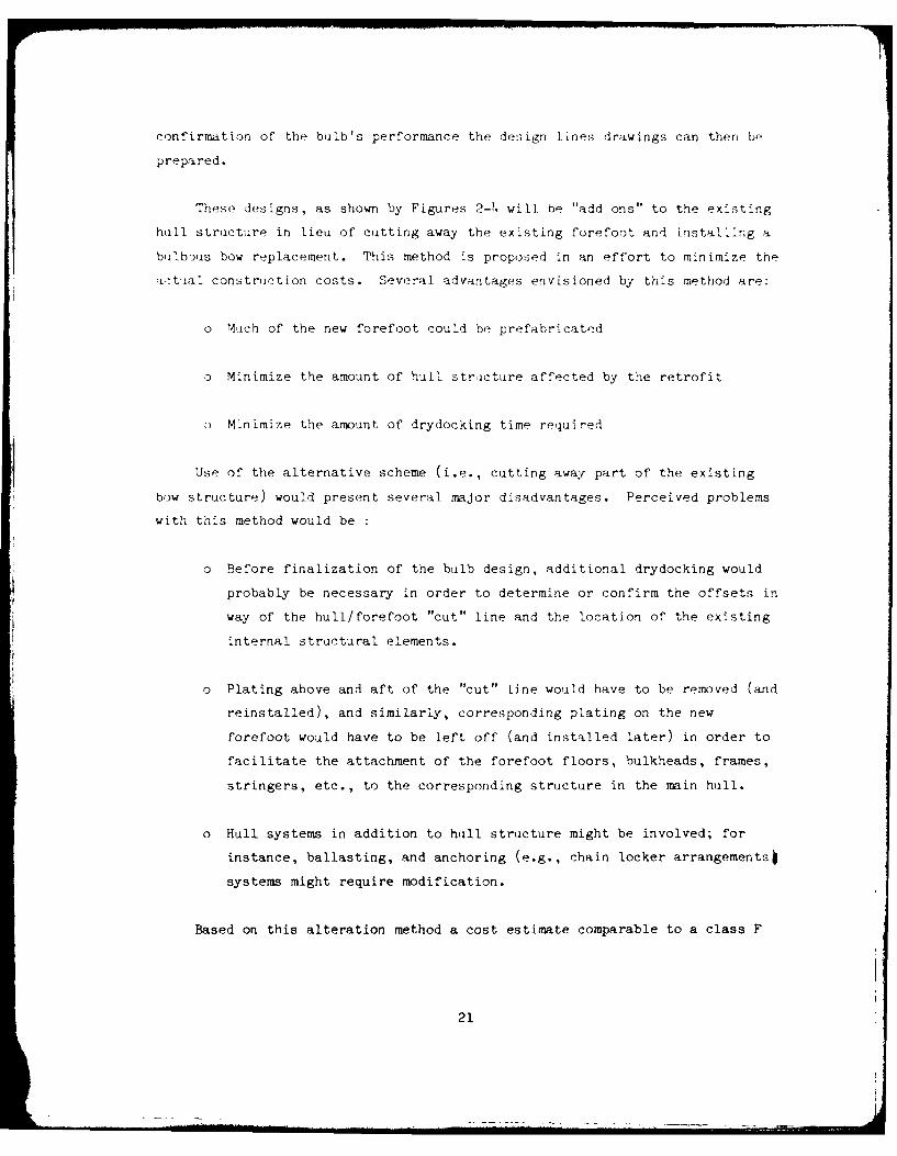
confirmation of the bulb's performance the design lines drawings can then be
prepared.
These designs, as shown by Figures 2-4 will be "add ons" to the existing
hull structure in lieu of cutting away the existing forefoot and installing a
bulbous bow replacement. This method is proposed in an effort to minimize the
a'tal constriction costs. Several advantages envisioned by this method are:
o Mtich of the new forefoot could be prefabricated
o Minimize the amount of hull stricture affected by the retrofit
o Minimize the amount of drydocking time required
Use of the alternative scheme (i.e., cutting away part of the existing
bow structure) would present several major disadvantages. Perceived problems
with this method would be
o Before finalization of the bulb design, additional drydocking would
probably be necessary in order to determine or confirm the offsets in
way of the hull/forefoot "cut" line and the location of the existing
internal structural elements.
o Plating above and aft of the "cut" line would have to be removed (and
reinstalled), and similarly, corresponding plating on the new
forefoot would have to be left off (and installed later) in order to
facilitate the attachment of the forefoot floors, bulkheads, frames,
stringers, etc., to the corresponding structure in the main hull.
o Hull systems in addition to hull structure might be involved; for
instance, ballasting, and anchoring (e.g., chain locker arrangementsi
systems might require modification.
Based on this alteration method a cost estimate comparable to a class F
21
estimate was performed as shown in Table 14. Savings in this estimate could
be achieved if the drawings and construction were performed at a commercial
shipyard. Further savings could also be anticipated by using furnacing
mockups and plate sub assemblies for fabrication of the "nose" (i.e., that
part of the bulb forward of the point of maximum sectional area). Further
savings for a class of ships could also be anticipated as the engineering work
and drawings would only have to be done once per class.
BOW BULB DESIGN METHODOLOGY
Care must be taken in the task of selection and design of bulbous bows
for ships which are considered to be appropriate candidates. Currently,
due to the complexity of bulb/hull hydrodynamic interactions as well as
lack of reliable theoretical assets, the contemporary bulbous bow design
technique is heavily reliant on historical data; and refinement of the initial
design must be based on model test experiments with specific bulb/hull
combinations.
On the basis of the known available data and other information in the
literature, three seperate approaches to the design of bow bulbs can be
readily envisioned:
1. Bow Bulbs Design Without Use of Design Charts - In this design process
designers are completely unfettered by any prescribed procedures or
constraints. The designer's experience and judgement is supported by the
results of many experimental investigations of bow bulbs which are documented
in the literature. These findings are studied, sifted, and consolidated into
a number of design-guidance statements for use in shaping bow bulbs.
The success of this approach depends largely on the designer's
interpretation and use of the existing body of miscellanous and sometimes
conflicting information. By following this approach, the designer has no
reliable way of predicting the quantitative effect that a bulb can be expected
to have on ship resistance and shaft horsepower. However, for fine-lined
22
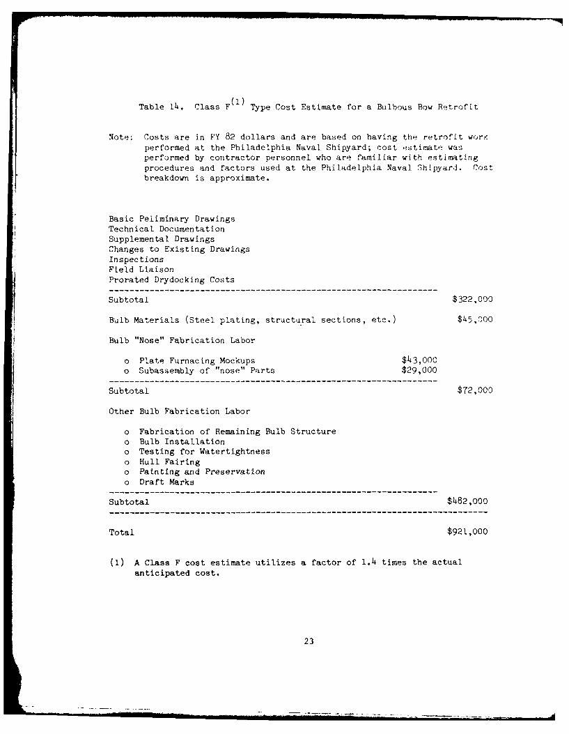
Table 14. Class F (I) Type Cost Estimate for a Bulbous Bow Retrofit
Note: Costs are in FY 82 dollars and are based on having the retrofit workperformed at the Philadelphia Naval Shipyard; cost estimate wasperformed by contractor personnel who are familiar with estimatingprocedures and factors used at the Philadelphia Naval Shipyard. Costbreakdown is approximate.
Basic Peliminary DrawingsTechnical DocumentationSupplemental DrawingsChanges to Existing DrawingsInspections
Field LiaisonProrated Drydocking Costs
Subtotal $322,000
Bulb Materials (Steel plating, structural sections, etc.) $45,000
Bulb "Nose" Fabrication Labor
o Plate Furnacing Mockups $43,000o Subassembly of "nose" Parts $29,000
Subtotal $72,000
Other Bulb Fabrication Labor
o Fabrication of Remaining Bulb Structureo Bulb Installationo Testing for Watertightnesso Hull Fairingo Painting and Preservationo Draft Marks
Subtotal $482,000
Total $921,000
(1) A Class F cost estimate utilizes a factor of 1.4 times the actualanticipated cost.
23

ships (having block coefficients of less than 0.60), encompass Lg most of the
Navy auxiliary and amphibious warfare ships, some guidelines can be set forth
reflecting the general consensus of the literature (Reference (3,4)).
Reference (5) was an effort to provide some guidelines to assist the naval
architect during the initial stages of developing a bulbous bow.
2. Bulb Design by the Use of Design Charts - More rigorous bow bulb
design methods, based on historical data, were attempted by Taylor, Kracht,
and several other investigators.
Among all these studies, Reference (6) may be considered as the most
definitive. This paper contains quantitative information for the initial
design of bow bulbs and evaluation of the associated change in horsepower.
Design charts which are presented herein are based on analysis of routine test
results at the Maberg & Berlin Model Basins, supplemented by results of
additional tests to fill in the data. The design charts cover a wile range of
hull forms with C B's ranging from 0.56 to 0.82 at increments of 0.02, which
were fitted with a variety of bow bulbs and tested over a range of Froude
Numbers. One of the shortcomings of Reference (6) is that the independent
variation of the different bulb parameters to derive design charts, bulb/hull
interaction other then CB (i.e., entrance angle, Cp, etc.) and the
interrelations between the bulb parameters are neglected (see Appendix A).
Thus it is essential that the designer's judgement be coupled with the use of
the curves in the design charts. The advantage of using these design charts
is that they can be used to judge the effect of bulb design variations on the
required power of a bulbous bow ship and thereby serve to assist in decision
making. Reference (6) attempted to use these charts to provide a near-optimum
bulb design methodology (assuming that the charts were fundamentally valid).
Two LHA 1 retrofit bulbs based on this methodology were designed and tested at
the David Taylor Naval Ship Research and Development Center (DTNSRDC). While
the results obtained were encouraging, further model testing to involve
different hull forms will be required to ensure the validation of this
technique.
24
3. Bow Bulb Design Through Numerical Techniques - Currently little
research has been done in development of numerical techniques for predicting
the characteristics of bulbous bows. However, one computer program that has
shown promise is the XYZ Free Surface (XYZFS) program. To date this program
has already been applied in calculating the wave-making resistance of hull
forms with sonar domes and shows good correlation with model test results.
Therefore we anticipate that if the proper method of modeling a bulbous bow
can be found, XYZFS will become a valuable tool for the bulbous bow designer.
Towards this objective, research is currently underway on two LHA 1 bow
bulbs. These bulbs were designed by application of the Kracht method
(described earlier in this section). It is hoped that, by this analysis, a
better understanding of the parameters that have thus far shown the greatest
influence on the performance of bulbous bows can be achieved.
CONCLUSIONS
Through the development of a systematic cost/benefit analysis it has beenshown that the retrofitting of bulbous bows will provide significant life
cycle fuel savings. The procedure developed was based upon:
o Speed/power relationships for the ship in calm water both with and
without bulb
o Total steaming time
o Speed/time distribution for the ship as it is deployed
o Specific fuel consumption over the range of operating speeds
Based upon currently available information it has been shown that among
the ships most likely to benefit from such a program are the LHA 1, LPD 4,
LPD 1, AGF 3, and LCC 19 class ships. Savings in fuel costs for these ships
will be, at a minimum, $96,000 per year per ship.
25

It must be stressed that once the decision to retrofit a bulb is made, a
series of hydrodynamic model tests should be performed to validate the
predicted performance improvement of the selected bulb design. Though the use
of historical data and design charts can help the designer select a candidate
bulb design these procedures can only be considered an adjunct to the overall
design procedure. Soon the use of numerical modeling techniques will also
become a part of this process.
For the ships recommended to undergo a bulbous bow retrofit a complete
ship alteration (SHIPALT) package, including detailed cost estimates must be
prepared. This work is being done on the first three ship clases which show
the shortest payback period. In an effort to reduce the overall costs
involved it has been suggested in this paper that the retrofit be accomplished
by "adding-on" to the existing hull structure rather than cutting away the
existing forefoot and installing a bulbous bow replacement.
This effort has shown that through the retrofitting of selected ships
with bulbous bows a viable way has been found to reduce the fuel requirements
of the fleet. However, until a bulb retrofit program is implemented, the Navy
will pay thousands of dollars more in fuel costs than necessary for every year
that this program is delayed. Further, continued delays in initiating such a
program will result in the removal of candidate ships from consideration as
their remaining years of service life diminish beyond the critical payback
point. Accordingly, the authors strongly encourage incorporation of a bulb
retrofit program into the Navy's overall conservation energy program as soon
as possible.
26

REFERENCES
1. Vincent, S. A., "Merchant Vessel Lines," Marine Engineering and Shipping
Age, March 1930, pp 134-153.
2. "A Study of the Benefits and Costs of Retrofitting Bow Bulbs on USN
Auxiliary and Amphibious Warfare Ships," NAVSEA Report 3213-82-04, April
1982.
3. Hhhnel, G., and Labes, K.H., "Systematic Resistance Tests for Fast Cargo
Ships, with and without Bow Bulbs," BSRA Translation No. 3112.
4. Research on Bulbous Bow Ships, Part 1 A, "Still Water Investigations into
Bulbous Bow Forms for a Fast Cargo Liner," Prof. Dr. IR WPA Van Lammeren,
IR R Wanab, Netherland Ship Model Basin Report No 745, October 1965.
5. "A Guide for Integrating Bow Bulb Selection and Design into the U.S.
Navy's Surface Ship Hull Form Development Process," NAVSEA Technical Note
No. 835-55W-TN-O001, April 1983.
6. Kracht, A.M., "Weitre Untersuchungen Uber die Anwendung von Bugwulsten,"
VWS Bericht No. 811/78, Berlin, 1978.
7. "Ship Steaming Hours and Fuel Consumption for FY 81 (October 1980 to
September 1981)," a compilation prepared by OPNAV 413.
8. "Powering Prediction of the LPD Represented by Model 4910," DTNSRDC
Report 032-H-01, December 1961.
27
APPEND[X A
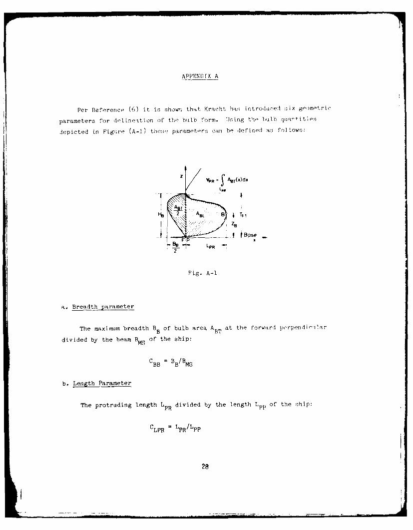
Per Reference (6) it is shown that, Kracht ha!; introdluced six geomt-tric
parameters for delineation of the bulb form. Using the bulb qutittie-s
depicted in Figuire (A-i) these parameters can be defined as follows:
zz
~~ LM
7-7,
B BTse
C B BB P BBB
b. Length Parameter
The protruding length L PRdivided by the length L Ppof the ship:
CLPR L LPR/L PP
28

c. Depth Parameter
The height ZB of th" foremost p7int of the bulb over the baseline dividd
by the draft Tp at the forward perpendicular:
:~1 ZB/TpB /TP
d. Cross-Secton Parameter
The cross-sectional area ABT of the buhous bow at the forward
perpendicula divided by the midship-section area AM Of the ship:
CABT ABT/AMS
e. Lateral Parameter
The area A of the protruding bulb in the longitudnal plane divided byBL
the midship-section area AMS of the ship:
CABL = ABL/AME
f. Volumetric Parameter
The volume V of the protruding part of the bulb livided by th volume ofPH
displacement VWL of the ship:
C~p =V V/VwCVPR vPH / WL
An additional bulb parameter HB is suggested by Reference (4), where HB
is defined as the height of the bulb at the forward perpendicular.
The selection of the height and the distance from the baseline to the
bottom of the bulb are matters of Judgement, the bulb height HB is constrained
by two requirements: I) it mist be large enough to enable the required
29

cross-section area ABT to be developed; and 2) the top of the bulb must be an
appropriate distance below the design waterline. At the same time, marked
flatness of the top of the bulb should be avoided to minimize the potential
for cavitation as the ship pitches and heaves. In general, it is considered
that the value of Z B/H B should be between 0.5 and 0.9. A tentitive value of
HB can be obtained by the following formula:
HB (4ABT BB
30
1. 00
0. 99
0. 98
cc
0. 97 -
_0.96
0. 95
20.940.. A
0. 93
0. 92
0.91 ,0.4 0.5 0.6 0.7 0.8 0.9 1.0
5PEED-LENGTH RATIO
FIGURE 1. Shaft Horsepower Ratio (Bulbous Bow to Conventional Bow) for anAmphibious Warfare Type Ship Displacement=17,000 tons
31
CL)
__ 0
T-I
nw I
320
......

0 4
I0
IS.
____ __ - 4--)
I 0)
- I
330 -
___________ - ---
C-
LU
I 4
..................

LI