AD-A142 186 21ST PUMP ING STATION RETTENDORFAOWA …
84
AD-A142 186 21ST STREF PUMP ING STATION RETTENDORFAOWA HYDRAULIC 1/I MD EVSAONUAMEUEE AEWEXPER MENT STA ON V CKSBRR MS NDNA. R R COPELAND UNCLASSIF IED APR 84 WES/TN HL84-5 U/ 13/2 N -E ; hEh1h
Transcript of AD-A142 186 21ST PUMP ING STATION RETTENDORFAOWA …

AD-A142 186 21ST STREF PUMP ING STATION RETTENDORFAOWA HYDRAULIC 1/IMD EVSAONUAMEUEE AEWEXPER MENT STA ON V CKSBRR MS NDNA. R R COPELAND
UNCLASSIF IED APR 84 WES/TN HL84-5 U/ 13/2 N
-E ; hEh1h

1111 1. 12 .0
IIIl'2liiiiiiiiiii~lj ___ __ 1.

V TECHN9k ,REPORT HL-84-5
US Amy Crps21st STREET PUMPING STATION,of EngneersBETTENDORF, IOWA
I , - . HYDRAULIC MODEL INVESTIGATION
by
Ronald R. CopelandHydraulics Laboratory
___ U. S. Army Engineer Waterways Experiment Staton-P. 0. Box 631, Vicksburg, Miss. 39180
94
f 01
w i t ' , -- -a II 4~ELECTEN
p.JU Api 19194
Fina ReorPe a pp rovedS.FArm P Ebl i n eer itit Roc l and
LABO ATOY Rck slan, 11. 120"0 845

* I Destroy this report when no longer needed. Do notreturn it to the originator.
The findings in this report are not to be construed as anofficial Department of the Army position unless so
designated by other authorized documents.
The contents of this report are not to be used foradvertising publication, or promotional purposesCitation of trade names does not constitute anoffic:al endorsement or approval of the use of such
commercial products.

V
UnclassifiedSECURITY CLASSIFICATION OF THIS PAGE (When Dete Entered)
REPORT DOCUMENTATION PAGE BEFORE COMPLETIG FORM
A.RREPORT NUMBER SjIIENTS CATALOG NUMBER
Technical Report HL-84-5 A) T4 I T A4. TITLE (ad Subtitle) S TYPE OF REPORT & PERIOD COVERED
21st STREET PUMPING STATION, BETTENDORF, IOWA; Final reportHydraulic Model Investigation *. PERFORMING ORO. REPORT NUMBER
7. AUTHOR(e) S. CONTRACT OR GRANT NUMBER(e)
Ronald R. Copeland
S. PERFORMING ORGANIZATION NAME AND ADDRESS 10. PROGRAM ELEMENT. PROJECT. TASKAREA & WORK UNIT NUMBERS
U. S. Army Engineer Waterways Experiment StationHydraulics LaboratoryP. 0. Box 631, Vicksburg, Miss. 39180
11. CONTROLLING OFFICE NAME AND ADDRESS 12. REPORT DATE
U. S. Army Engineer District, Rock Island April 1984Clock Tower Building IS. NUMBER OF PAGESRock Island, Ill. 61201 77
14. MONITORING AGENCY NAME & ADDRESSIf different from Contolli.J Offlce) IS. SECURITY CLASS. (of thile report)
UnclassifiedISe. DECLASSI FICATION/ DOWNGRADING
SCHEDULE
1. DISTRIBUTION STATEMENT (of thl Report)
Approved for public release; distribution unlimited.
17. DISTRIBUTION STATEMENT (of the abetract mtered In Block 20. It different frem Report)
IS. SUPPLEMENTARY NOTES
Available from National Technical Information Service, 5285 Port Royal Road,Springfield, Va. 22161
It. KEY WOROS (Continue mn re ere elde It neceem and Identify by block nuiber)
Pumping stations--Iowa. (LC)Hydraulic models. (LC)Hydraulic machinery. (LC)Pumping machinery--Models. (LC)
I& ABfTRAcr aintame m reverseeb N noeeey adIdenttfy by block riuwSer)
A hydraulic model was used to evaluate the hydraulic performance of the21st Street Pumping Station Suap for the Bettendorf, Iowa, Local Flood Protec-tion Plan. The proposed pumping station consisted of five individual pump baysoriented perpendicular to a box culvert that will provide inflow from two di-rections. The performance of the original design was characterized by surfaceand submerged vortices. Surface vortices were eliminated by lowering the sump
(Continued)
DO I 173 mToNoFSWovssisoOLETE Unclassified
SECUmTY CLASSIFICATION OF THIS PAGE (When Dae Entered)

UnclassifiedSECURITY CLASSIFICATION OF THIS PAGI(Ulmm Datea SEu*o
20. ABSTRACT (Continued).
-floor elevation which increased submergence on the pump. Submerged vorticeswere no longer observed when surface roughness was added to the sump floorsand walls. The forebay in the original design was eliminated which providedfor considerable economic savings. The design developed as a result of themodel investigation operated satisfactorily at different sump water-surfaceelevations and with various combinations of pumps operating.,
Unclassified
59CURITY CLASIICATION OF THIS PA8EWhmi Date Efftmer)
t.F

IPREFACEThe model investigation of the 21st Street Pumping Station reported
herein was authorized by the Office, Chief of Engineers (OCE), U. S. Army, in
September 1981, at the request of the U. S. Army Engineer District, Rock
Island (NCR).
This investigation was conducted during the period October 1981 to
*August 1982, in the Hydraulics Laboratory of the U. S. Army Engineer Waterways~Experiment Station (WES), under the direction of Messrs. H. B. Simons, Chief
of the Hydraulics Laboratory, J. L. Grace, Jr., Chief of the Hydraulic Struc-
tures Division, and under the general supervision of N. R. Oswalt, Chief of
the Spillways and Channels Branch. Project engineers for the model study were
Messrs. R. R. Copeland and S. T Maynord, assisted by E. L. Jefferson.
Mr. B. F. Stanfield is acknowleged for his work in constructing the model.
This report was prepared by Mr. Copeland.
During the course of the study, Messrs. Sam Poak, Don Logsdon, S. K.
Nanda, and Rex Beach of NCR, and John S. Robertson of OCE visited WES to dis-
cuss the program of model tests, observe the model in operation, and correlate
test results with concurrent design work.
Commander and Director of WES during the course of this investigation
and the preparation and publication of this report was COL Tilford C. Creel,
CE. Technical Director was Mr. F. R. Brown.
+~~~~~~ . V " ": ; [ . . .
i .,. '
OtOn
II
COPY
-Z iA

Page
PREFACE . . . . . . . . . . . . . . . . . . . . .1
CONVERSION FACTORS, U. S. CUSTOMARY TO METRIC (SI) UNITS OFMEASUREMENT .. ... .......... ......... ........ 3
PART I: INTRODUCTION. .. ....... ......... ........ 5
The Prototype. .. .*.*.*.*.'.'.*.*.*.*...*.*.*.................5Purpose of the Model Study. .... ......... ........ 6
PART II: THE MODEL .. ....... .......... ......... 8
Description .. ... .......... ......... ..... 8Interpretation of Model Results. .. ....... .......... 8
PART III: TEST RESULTS .. .... ......... ............ 15
Method of Operation .. ... .......... .......... 15Original Sump Design .. ....... .......... ..... 15Modifications to Type I Design Swmp .. ... ............. 17Type 2 Design Sump. .... ......... ............ 26Type 3 Design Swmp. .... ......... ............ 31
PART IV: CONCLUSIONS. .... ......... ............. 35
REFERENCES .. ........ ......... ......... .... 37
TABLES 1-31
PLATES 1-6
2
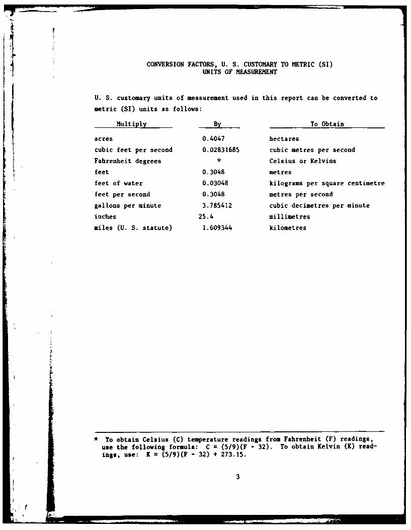
CONVERSION FACTORS, U. S. CUSTOMARY TO METRIC (SI)UNITS OF MEASUREMENT
U. S. customary units of measurement used in this report can be converted to
metric (SI) units as follows:
Multiply By To Obtain
acres 0.4047 hectares
cubic feet per second 0.02831685 cubic metres per second
Fahrenheit degrees Celsius or Kelvins
feet 0.3048 metres
feet of water 0.03048 kilograms per square centimetre
feet per second 0.3048 metres per second
gallons per minute 3.785412 cubic decimetres per minute
inches 25.4 millimetres
miles (U. S. statute) 1.609344 kilometres
* To obtain Celsius (C) temperature readings from Fahrenheit (F) readings,
use the following formula: C = (5/9)(F - 32). To obtain Kelvin (K) read-ings, use: K = (5/9)(F - 32) + 273.15.
3

J 00
IZo -'
s tt1, f,, 1 Z
V~oIVO ' VWCVklg3Nj 0i
-iT .. W
Z c_3 0
00
Idi
14~
1f' rf
LJ'L JL
\Vrrnflrnr1
4 - IL
Li8

21st STREET PUMPING STATION, BETTENDORF, IOWA
Hydraulic Model Investigation
PART I: INTRODUCTION
The Prototype
1. The city of Bettendorf, Iowa, is located on the Mississippi River
approximately 3 miles* upstream from Lock and Dam 15. The city of Davenport,
Iowa, borders Bettendorf on the west (downstream) and the cities of Rock
Island and Moline are located across the river in Illinois. These cities are
regionally known as the Quad Cities and are important industrial and commercial
centers for a large and prosperous agricultural area. Bettendorf's location
is shown on the vicinity map in Figure 1.
2. Bettendorf is protected from floods on the Mississippi River by
levees, but the city is subject to flooding from local interior runoff that
collects behind the river levee. The flood problem area consists of about
330 acres of extensively developed industrial, conmercial, and residential
property traversed by an important railroad and highway. The city's main
business district is located in the floodplain. Due to relatively high water
levels in Pool 15, which is adjacent to the city, gravity drainage into the
Mississippi River is usually impractical. Currently, local drainage in the
cities of Bettendorf and Davenport is diverted to the government sewer, which
parallels the levee and discharges into the river below Lock and Dam 15. The
sewer is inadequate to handle the runoff from significant local rainfalls.
3. The local flood protection plan for Bettendorf consists of a series
of earth levees, floodwalls, gated closure structures, drainage structures,
pumping stations, and channel improvements as shown in Figure 1. The
21st Street Pumping Station is one of two pumping stations proposed in the
plan and will be located on the existing government sewer. The plan calls for
closing the government sewer at the Bettendorf-Davenport city boundary when
the sewer reaches capacity. This will relieve pressure on the drainage
A table of factors for converting U. S. customary units of measurements to
metric (SI) units is presented on page 3.
5
structure through the city of Davenport by eliminating rainfall runoff from
Bettendorf. The Bettendorf runoff collected in the sewer would be discharged
into the Mississippi River through the 21st Street Pumping Station.
4. The 21st Street Pumping Station will have five 36-in. pumps with a
combined pumping capacity of 150,000 gpm. The pumps, which will discharge
directly into the Mississippi River through 36-in.-diam discharge lines
equipped with flap gates, will be located in individual pump bays. Sidewalls
will have a 1:4 convergence such that there will be a 0.75-in. clearance be-
tween the walls and the 60-in.-diam suction bell. The floor clearance will be
2.5 ft. The original design sump provided a minimum submergence of 2.4 ft on
the suction bell. The pump bays will be located perpendicular to the govern-
ment sewer, which is 7.5 ft high and 5.5 ft wide at the site. The station
will draw flow from both directions of the sewer in approximately equal quanti-
ties. Operating water-surface elevations will vary between 558.5* and 564.5.
Sump dimensions and flow rates are often related to the suction bell diameter
for comparison purposes. In these terms, characteristics of the original de-
sign of the 21st Street Pumping Station are:
Length (to pump center line) 3.7D
Width 1.8D
Floor clearance 0.50D
Wall clearance 0.012D
Minimum suction bell submergence 0.48D
Q/D5 / 2 * 1.20
Purpose of the Model Study
5. Pump performance can be adversely affected by unfavorable flow con-
ditions at the pump intake caused by low submergence of the pump impeller and
by unequal flow distribution entering the sump. Air entrainment, vortex ac-
tion, prerotation of flow (swirl) into the pump column, and pressure fluctua-
tions can occur and may result in cavitation, vibration, and uneven stresses
on the pump. Although, generalized studies are being conducted by the U. S.
* All elevations (el) cited herein are in feet referenced to the NationalGeodetic Vertical Datum (NGVD).Flow parameter, where Q = discharge in cubic feet per second and D suc-tion bell diameter in feet.
6

Army Engineer Waterways Experiment Station (WES) as part of the Electrical and
Mechanical R&D Program to improve pumping station inflow-discharge hydraulics
and eliminate or reduce these adverse effects, these studies have not yet pro-
duced sufficient information to develop design criteria needed for pump sumps
with conduit approaches.
6. The 21st Street Pumping Station has unique features that are not
adequately covered by existing design criteria. Flow approaches the station
perpendicular to the pump bays, a condition that could cause adverse circula-
tion in the sump and poor flow distribution in the pump bays. Suction bell
submergence is considerably lower than most general criteria recommend. The
location of the converging sidewalls is such that the suction bell clearance
is much less than that generally recommended. The model study was con' ei
to provide an assessment of the sump's hydraulic performance for a ran -f
anticipated operating conditions. The investigation was also intendee de-
velop practical modifications that would improve performance of the pL eL
station and/or reduce construction costs.
7 -*

PART II: THE MODEL
Description
7. The model of the 21st Street Pumping Station was constructed to an
undistorted linear scale ratio of 1:8 and of transparent plastic to allow ob-
servation of submerged flow conditions. A scale was attached to the backwall
of the type I original design sump and to the backwall of the government sewer
in subsequent design sumps to indicate water-surface elevations. The govern-
ment sewer was simulated for lengths of 80 ft in both directions from the sump
and was also constructed of transparent plastic. The model as originally de-
signed is shown in Figure 2.
8. Flow through the model was recirculated by centrifugal pumps. Each
pump column had its own separate pump to permit simulation of various flow
rates and selective operation of the pumps. Water levels were adjusted in the
model by adding or draining water. Flow from each pump was measured by paddle-
wheel flowmeters and displayed electronically. The flow rates were controlled
by automatic valves. Flow from each of the five pumps fed into a manifold
where it could flow to either of two headbays located at upstream ends of the
model. Flow to the headbays was measured by paddle-wheel flow6.eters, con-
trolled by automatic valves, and displayed electronically. Flow rates through
the pumps and into the headbays were controlled and monitored at a console
located adjacent to the model.
9. Various instruments and methods were used to measure the factors
that affect pump sump performance. Confetti and dye were used to observe and
photograph flow patterns in the sump. Velocities approaching the pump column
were measured with a paddle-wheel velocity meter. Visual observations were
used to determine vortex activity. Prerotation of flow (swirl) into the pump
column was measured by counting revolutions of a freewheeling vortimeter with
four zero-pitched blades mounted in the pump column (Figure 3). Electronic
pressure transducers were placed beneath the pump suction bells to measure
instantaneous pressure fluctuations (Figure 3); a time-history was recorded onstrip charts.
Interpretation of Model Results
10. The principle of dynamic similarity, which requires that ratios of
8

14)
4)
C14
ON.V

V|
VTRANSDUCER
%E
¥x
- -4
PRESSURE TRANSDUCERDIA. 2" (PROTOTYPE)
PUMP INTAKE
PRESSURE TRANSDUCER
PLAN VIEW ELEVATION
Figure 3. Flow condition monitors used in model investigation

forces be the same in model and prototype, is the basis for the design of
models and the interpretation of results. Models involving a free surface are
scaled to the prototype using the Froudian criteria because the flow phenomena
are determined primarily by gravitational and inertial forces. The general
relations expressed in terms of model scale or length ratio are as follows:
ScaleDimension Ratio Relation
Length L = L 1:8r
Velocity V = LI 2 1:2.83r
Time T = L1/2 1:2.83r
Discharge Qr = L 5 /2 1:181
Pressure P = L 1:8r
Values for length, velocity, time, discharge, and pressure fluctuation can be
transferred quantitatively from model to prototype by means of the scale rela-
tions above. Unless otherwise noted, all results reported herein will be
given in prototype units.
11. Viscous effects can also influence flow patterns and formation of
vortices. Daggett and Keulegan (1974) conducted vortex similarity tests using
drain vortices in cylindrical tanks and defined a limiting Reynolds number
R=Av
where
R = Reynolds number
Q = discharge
A = orifice radius
v = kinematic viscosity
which must be greater than 5(10)4 to yield viscous effects negligible. The
Reynolds number by this definition for the 21st Street model varies between
8.4 x 10⁴ and 1.6 x 10⁵ depending on temperature, thus indicating minimal vis-
cous effects in the model. The work of Anwar and Amphlett (1980) with in-
verted pipe intakes shows that surface tension and viscosity effects become
negligible when the radial Reynolds number
11
I1
- , .. " ,-

V
Rr =
(where h equals submergence above bottom of intake pipe) is greater than43(10) . Using this definition for Reynolds number, it was determined the
21st Street model (Rr = 1.0 X 10⁴ - 1.7 x 10 5) was free of viscous and surface
tension effects at water-surface elevations below 563.0 and where the tempera-
ture was greater than 650 F. Hecker (1981) reviewed available model-prototype
comparisons of free surface vortices and found 16 projects where model flows
were scaled by the Froudian criteria. Fourteen of these projects had model
and prototype vortices essentially equal and five of the projects had vortices
weaker in the model than in the prototype. Hecker concludes from the model-
prototype comparisons that designs that were developed from Froude-scale model
tests to be vortex-free were indeed vortex-free in the prototype, and those
having weak vortices in the model had weak vortices in the prototype. No
cases were found where a weak model vortex corresponded to a strong prototype
vortex resulting in operating problems.
12. There are currently insufficient data to establish definite accept-
able limits of uneven flow distribution, vortex activity, and pressure fluctua-
tion; however, general guidelines have been considered and are used at WES to
develop satisfactory sump designs. The flow distribution approaching the pump
column should be fairly uniform because uneven distributions usually cause ex-
cessive levels of the other indicators. In this model investigation, veloci-
ties were measured at a depth halfway between the floor and the bottom of the
suction bell. Every attempt is made to eliminate surface and submerged vor-
tices. The types of vortex formations and the stages of surface vortex de-
velopment observed in this study are shown and defined in Figure 4. The
severity of swirl is expressed as a dimensionalized rotational flow indicator,
R. The rotational flow indicator is the ratio of the tangential velocity at1
the tip of the vortimeter blade to the average axial velocity in the pump col-
umn, and is equal to the tangent of the indicated swirl angle as used by many
investigators. The rotational flow indicator is computed using the following
formula:
Ri Va
12!1

WATERLEVEL
SURFACE VORTEX
'WALL VORTEX
FLOOR VORTEXSECTION A-A
VORTEX FORMATIONS
SURFACE DIMPLE WITH NO AIR ENTRAINMENT
A
S SURFACE DEPRESSION BECOMES DEEPER
S A TAIL DEVELOPS WHICH MAY HAVE A ROTATINGWATER CORE BENEATH IT, DETECTABLE BY DYE
C
S AIR ENTRAINMENT OCCURS IN THE FORM OF AIRBUBBLES DRAWN INTO THE SUCTION BELL
000
D
FULLY DEVELOPED VORTEX WITH OPEN AIRCORE INTO THE SUCTION BELL
E
STAGES OF SURFACEVORTEX DEVELOPMENT
Figure 4. Vortex formations
,,f t3 f
where
u = nnt/60
n = angular velocity of vortimeter, rpm
2 = length of vortimeter blade (pump column diameter), ft
V a= average axial velocity in pump column, fps
The rotational flow indicator has the same value in model and prototype and
may be used to compare performance of sumps with different sizes and dis-
charges. To ensure satisfactory sump performance, WES recommends that the
rotational flow indicator be less than 0.09, which is equivalent to an indi-
cated swirl angle of 5 deg. Maximum pressure fluctuations, measured as feet
of water, represent turbulence and/or the passage of low-pressure cores across
the pressure transducer located directly beneath the center line of the pump.
In the model investigation, pressures were recorded for a minimum of 7 min
(prototype). WES considers recorded pressure fluctuations greater than 4 ft
of water as excessive. Using these guidelines, it is believed that acceptable
pump sump design can be accomplished through the model investigation procedure.
14
: , : , .. .. . . . _ .. . I I I I4

PART III: TEST RESULTS
Method of Operation
13. The proposed pumping station consists of five pumps designed to
operate between water-surface elevations 558.5 and 564.5. The range of sump
water-surface elevations at which various numbers of pumps would be operating
is shown below:
Number of Sump Water-Surface ElevationPumps Operating Minimum Maximum
1 558.5 560.75
2 559.5 562.0
3 560.75 562.5
4 561.5 563.0
5 562.0 564.5
Due to the large number of possible combinations of pumps operating at various
sump water-surface elevations, a few operating conditions were chosen to com-
pare various modifications. These were generally pump 5 operating between
el 558.5 and 561.5, and all five pumps operating between el 562.0 and 564.5.
Tests were usually conducted at 1-ft intervals within this range. The original
and final designs were tested with several additional operating conditions.
The tests were conducted with a discharge of 67 cfs per pump. Flow entered
the sump in equal quantities from both directions of the government sewer.
Original Sump Design
14. Flow from the government sewer entered the forebay of the type 1
(original) design sump (Figure 5) through three 10-ft wide by 5-ft-high gate
openings. Flow through the center opening was deflected by the two type 1
(original) design baffles. The five pump bays were 21.08 ft long and 9 ft
wide and were oriented perpendicular to the government sewer. The sidewalls
converged toward the 5-ft-diam pump suction bell at an angle of 14 deg such4|
that the clearance between the suction bell and the walls was 0.75 in.
(0.012D). The backwall clearance was also 0.75 in.
15. The hydraulic performance of the type 1 design sump was found to be
15
tI

-. 57.0 FT35.46FT
5FT 5.0FT
5.0 FT A' k
BAFFLE LCONVERING SDEWAL
Figure ~ ~ 1. F.Tp Idsgnsa
3.5 F R16
p *1 - .
w
unsatisfactory. Surface vortices were observed at low sump water-surface ele-
vations. Submerged vortices were observed off the floor and sidewalls whenmore than one pump was operating. Eddies occurred in the pump bays becausethe flow did not enter uniformly. Swirl and pressure fluctuations were within
acceptable limits for most of the operating conditions tested. The generally
acceptable level of swirl is apparently attributed to the closeness of the con-
verging sidewalls to the suction bell. The occurrence of submerged vortices
may also be partially attributed to the sidewall's location. Test results
with various combinations of pumps operating and a range of sump water-surface
elevations are shown in Tables 1-4. Measured velocities and flow patterns in
the pump bays for three operating conditions are shown in Plate 1.
Modifications to Type 1 Design Sump
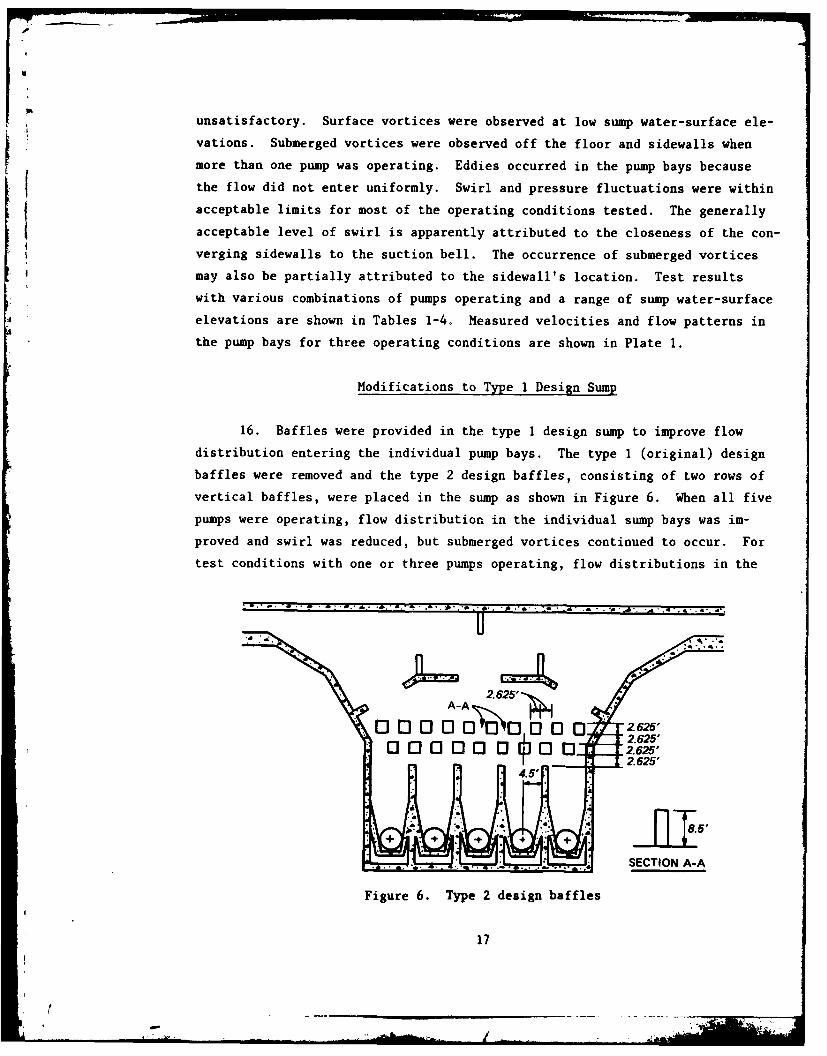
16. Baffles were provided in the type 1 design sump to improve flow
distribution entering the individual pump bays. The type 1 (original) design
baffles were removed and the type 2 design baffles, consisting of two rows of
vertical baffles, were placed in the sump as shown in Figure 6. When all five
pumps were operating, flow distribution in the individual sump bays was im-
proved and swirl was reduced, but submerged vortices continued to occur. For
test conditions with one or three pumps operating, flow distributions in the
* 4. . . . . . .4. d,
A-A -2'4
."2.625'
nooo 0 oo1j3 3 2.625'2.625'
. .. .. { SECTION A-A
Figure 6. Type 2 design baffles
17
_ _ _ _ _

-
individual pump bays were not improved. Swirl increased and in some cases the
severity of surface vortices increased. Submerged vortices continued to occur.
Test results for one, three, and five pumps operating are shown in Table 5;
measured velocities and flow patterns are shown in Plate 2.
17. Tests were conducted to determine if rounded pier noses in combina-
tion with the type 2 design baffles would improve the flow distribution and
sump performance for single pump operations. Two pier noses were tested (Fig-
ure 7). The type 2 design pier nose was semicircular with a diameter equal to
the sump divider wall thickness. The type 3 design pier nose had a diameter
twice the sump divider wall thickness. The pier noses were tested with one
pump operating in pump bay 5; results are shown in Tables 6 and 7. Swirl was
slightly improved with the type 3 design pier nose, but surface and submerged
vortices continued to occur. The rounded pier noses did not significantly im-
prove hydraulic conditions in the sump.
18. An attempt was made with the type 3 design baffles to direct more
flow down the center of the pump bays by moving the baffle rows closer to the
pump bays and interchanging the baffles with the baffle spacings as shown in
R-=.75'DDE jl* 5 j
TYPE 2 DESIGN TYPE 3 DESIGN
Figure 7. Type 2 and 3 design pier noses with type 2 design baffles
18
* . ~:

Figure 8. This design was tested with pump 5 operating alone and with five
pumps operating; results are shown in Table 8 and Plate 3. This design pro-
vided no improvement over the type 1 (original) design sump when one pump was
operating and was less effective than the type 2 design baffles when all five
pumps were operating.
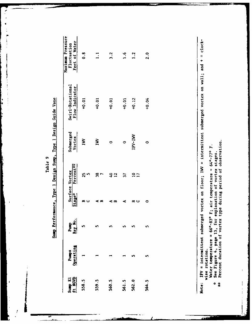
19. Guide vanes (or divider walls) were tested to determine if flow
distribution could be improved. The type 3 design baffles were removed and
the type 1 design guide vane (Figure 9) was placed in pump bay 5 and tested
with one and five pumps operating. Swirl was significantly lower with the
guide vane for single pump operations, but surface vortices were just as
severe as without the guide vane. In addition, submerged vortices were ob-
served with the guide vanes that were not observed with the original design.
Insufficient data were taken to make reliable comparisons for five pumps
operating, but the type 1 design guide vane had excessive swirl and surface
and submerged vortices with the sump water surface at el 562.0. Results of
these tests are presented in Table 9 and Plate 4.
20. Converging sidewalls similar to those in the 21st Street Pumping
Station were concurrently tested at WES as part of the generalized pumping
station research program. These tests were made in a straight approach chan-
nel, so that the flow distribution approaching the pump was uniform. The
21st Street Pumping Station's type 1 (original) design sidewalls had a minimum
2.625"'
A-A
Figure 8. Type 3 design baffles
19
- '

+ 9.75'
8.80' 0.95'
SECTION A-A
A
Figure 9. Type I design guide vane
clearance of O.012D, where D is the suction bell diameter. Sidewall clear-
ances of 0.05D, 0.08D, and 0.17D were tested in the generalized model. Tests
conducted at appropriately scaled flow rates and submergences in the gener-
alized model demonstrated that submerged vortices would occur when the side-
wall clearance was 0.05D. When the sidewall clearance was 0.08D no submerged
vortices were observed at flow rates comparable to those expected at the
21st Street Pumping Station. The tests in the generalized model demonstrated
that even with uniform flow distribution, submerged vortices would occur in
the 21st Street Pumping Station sump with the type 1 (original) design converg-
ing sidewalls with only a clearance of 0.012D. It was concluded that the side-
wall clearance should be increased.
21. The sidewall clearance was increased to 0.10D (0.5 ft) with the
type 2 design sidewalls (Figure 10). This design was tested in pump bay 5 in
combination with the type I design guide vane for one and five pumps operating;
results are shown in Table 10. The type 2 design sidewalls were not success-
ful in eliminating submerged vortices. This failure is attributed to the con-
tinued poor flow distribution in the pump bay. Swirl increased significantly,
well beyond recommended limits, but surface vortex development was essentially
the same. Pressure fluctuations also became excessive with five pumps operat-
ing. Although hydraulic performance deteriorated with the type 2 design
20
f .....

2. 10' 2.40'
I --7 .----V 0.50'
.g
Figure 10. Type 2 design sidewalls
sidewalls, it was felt that a minimum wall clearance of 0.10D would be neces-sary for eventual elimination of submerged vortices. The type 2 design side-walls were therefore retained and further attempts to improve flow distribu-
tion were made.
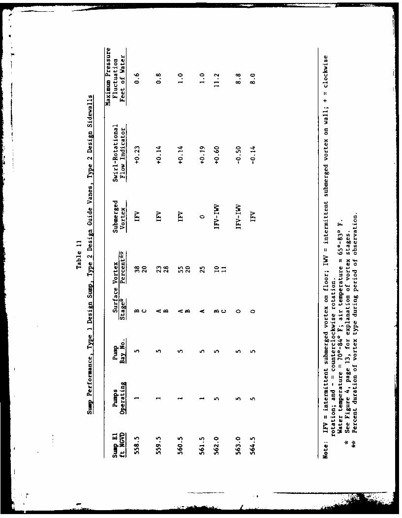
22. The type I design guide vane was removed from pump bay 5 and adouble guide vane (Figure 11) was installed. This type 2 design guide vane
was tested in combination with the type 2 design sidewalls for one and fivepumps operating (Table 11 and Plate 4). The type 2 design guide vane did not
provide any significant improvement over the type I design guide vane. Oneguide wall would be easier to construct than two, so the type I design guide
vane was put back into the model.
23. Horizontal vortex suppressor beams were added to pump bay 5 incombination with the type I design guide vane and the type 2 design sidewalls
in an attempt to reduce surface vortices. Location and sizing of the beams
(Figure 12) were based on a design from the generalized pumping station re-
search program at WES. The type 1 design vortex beams were tested for one and
~21

8.00
6.83' 1. 17'
fA~f liii SECTION A-A
iliilii
3.0'+.00' 3.00"
Figure 11. Type 2 design guide vane
15.00'
+ 8. 75'
5.50',
EL 564.5
EL 553.6C1
-- CL I 59 -
EL 553.6,Z
CON VERGING]SIDEWALLS
(TYPE 2)
9.00" SIDE VIEW
PLAN VIEW
Figure 12. Type 1 design vortex suppressor beams with type I design guidevane and type 2 design sidewalls
3ti
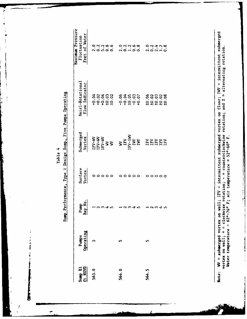
five pumps operating; results are shown in Table 12. The addition of the
vortex beams to the type 1 design guide vane and the type 2 design sidewalls
reduced surface vortices significantly; stage C vortices were only observed at
the minimum sump elevation of 558.5. Swirl was also significantly reduced,
although it remained excessive for five pumps operating. Pressure fluctua-
tions were reduced but were still excessive when five pumps were operating
with a sump water surface'at el 564.5. Submerged vortices continued to occur
for all conditions tested.
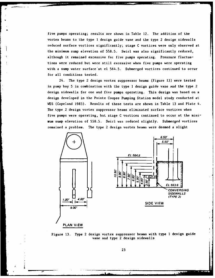
24. The type 2 design vortex suppressor beams (Figure 13) were tested
in pump bay 5 in combination with the type I design guide vane and the type 2
design sidewalls for one and five pumps operating. This design was based on a
design developed in the Pointe Coupee Pumping Station model study conducted at
WES (Copeland 1983). Results of these tests are shown in Table 13 and Plate 4.
The type 2 design vortex suppressor beams eliminated surface vortices when
five pumps were operating, but stage C vortices continued to occur at the mini-
mum sump elevation of 558.5. Swirl was reduced slightly. Submerged vortices
remained a problem. The type 2 design vortex beams were deemed a slight
6.50'
5.50'
EL 564.5
! , EL 553.6
) [ CONVERGINGSIDEWA L L S(TYPE 2
~SIDE VIEW
9.00'/
PLAN ViEW
Figure 13. Type 2 design vortex suppressor beams with type 1 design guidevane and type 2 design sidewalls
23
a9'-..

improvement over the type 1 design vortex beams.
25. The effect of lengthening the pump bay by extending the divider
wall was tested in pump bay 5 for one and five pumps operating (Table 14).
The type 1 design wall extension (Figure 14) was tested in combination with
the type 1 design guide vane, the type 2 design vortex suppressor beams, and
the type 2 design sidewalls. The divider wall did not provide for any sig-
nificant improvement in sump performance.
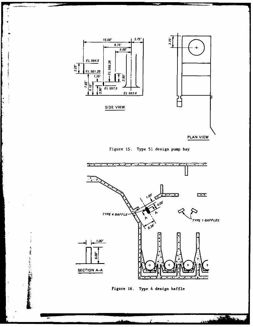
26. A sump design without converging sidewalls was developed at WES as
part of the pumping station research program for sumps with uniform flow dis-
tribution approaching the pump. This design (type 51 pump bay), shown in Fig-
ure 15, was tested in pump bay 1 for single pump operations and with five
pumps operating (Table 15). The type 51 design pump bay did not perform
satisfactorily with the poor flow distribution that occurs in the 21st Street
Pumping Station.
27. The type 4 design baffle was located in front of one of the two
side gate openings (Figure 16) and was intended to deflect flow away from the
side pump bay in order to improve overall flow distribution in the sump. The
effect of this design on the type 51 design pump bay is shown by comparing
Tables 15 and 16. When all five pumps were operating at a water-surface ele-
vation of 562.0, the baffles were successful in significantly improving flow
distribution into the side bays. However, as the water level increased to
el 564.5 the baffles became less and less effective. Apparently,
6.22'
DIVIDERWALLEXTENSION
Figure 14. Type 1 divider wall extension
24
[!b
15.00' 3.75'
8.75'5.00'+
EL 564.5 '
Pl EL 56.251.25'
EL_5_ZEL 553.6
SIDE VIEW
PLAN VIEW
Figure 15. Type 51 design pump bay
TYPE : '4 .'.... 4 :--~.... ** 4. BAFL
TYPEE 4 BAFFLES
SECTION A-A
Figure 16. Type 4 design baffle

deflector-type baffles would require different configurations for each operat-
ing condition, making their use impractical.
28. The tests conducted on the type 1 (original) design sump with vari-
ous modifications were unable to develop a sump design with satisfactory hy-
draulic performance. Features that provided for significant improvement in the
sump's performance were the type 1 design guide vane and the type 2 design vor-
tex suppressor beams. Results from the generalized pumping station research
program at WES indicated that type 2 design sidewalls were also desirable.
After viewing the model in operation and discussi-g test results of the type 1
design sump, engineers from the U. S. Army Engineer District, Rock Island, de-
cided to discontinue attempts to improve this design so that testing could
proceed on a revised sump design that would be more economical to construct.
Type 2 Design Sump
29. The type 2 design sump, designed by the Rock Island District, would
be more economical to construct and was similar to an existing prototype pump-
ing station at Marshalltown, Iowa, which has operated satisfactorily since
construction. The type 2 design sump had no forebay so that each pump bay was
connected directly to the government sewer and had individual gates (Fig-
ure 17). The type 2 design sump had the type I (original) design sidewalls
with a suction bell clearance of 0.012D. The type 1 (original) design gates
were 5 ft high by 5 ft wide and were located 13.35 ft upstream from the pump
center line. The total length of the individual pump bays was 22.65 ft. Re-
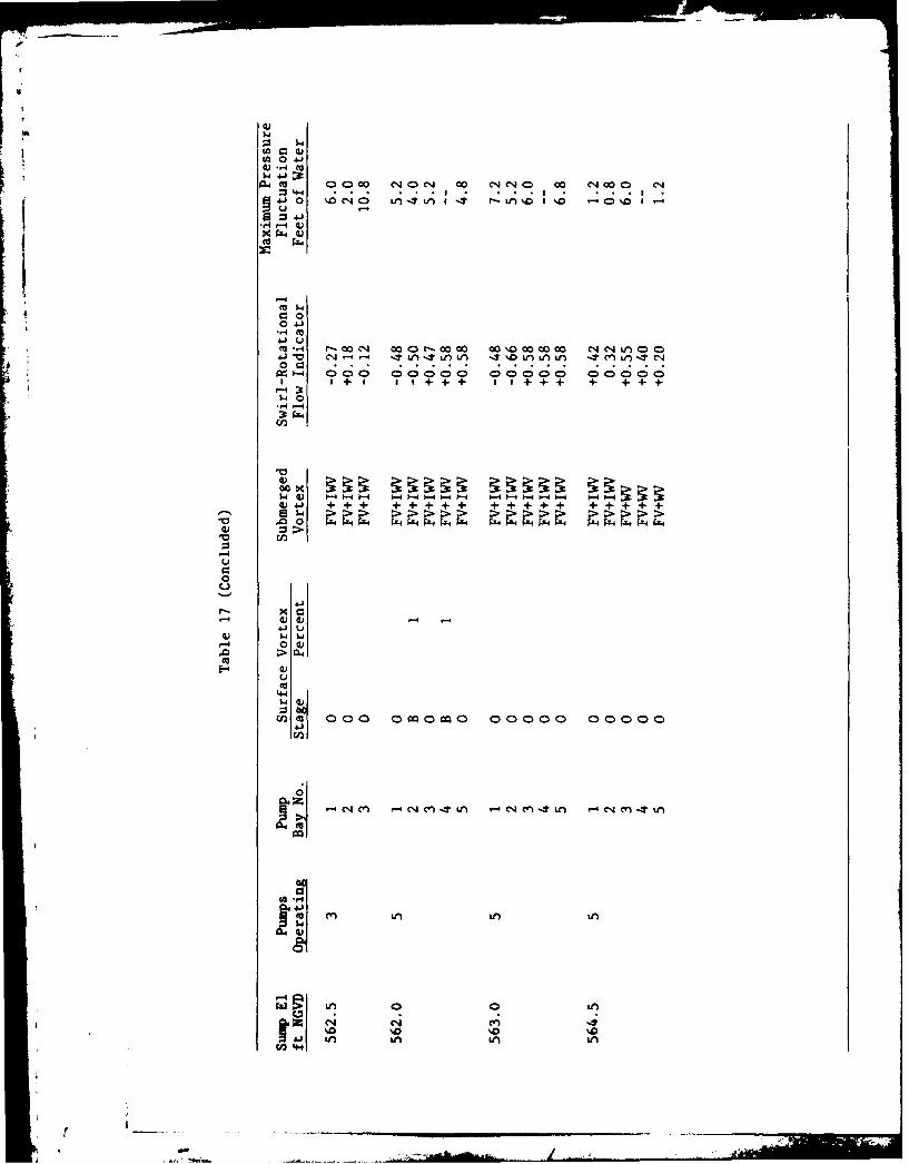
sults of testing this design are shown in Table 17; measured velocities and
flow patterns are shown in Plate 5.
30. For single pump operations, the type 1 design sump performed
slightly better than the type 2 design sump. Surface vortices occurred because
of the low sump water-surface elevations. Submerged vortices occurred with the
type 2 design sump but were not observed in the type 1 design sump. Swirl was
within recommended limits for the type 1 design sump but exceeded acceptable
values during one test with the type 2 design sump. Pressure fluctuations
were within acceptable limits for both designs. The similarity in performance
of the two designs for single pump operations is attributed to the relatively
low velocities in the government sewer so that adverse eddies are not set up
when flow enters the pump bay.
26

I.I'
• I .-'1 E . . . E__4
+ 7
WALL CLEARANCE 0.063 FT
FLOOR CLEARANCE 2.5 FT
SUCTION BELL DIAMETER 5 FT
u P . .Type 2 design sump
31. The hydraulic performance of the type 2 dpoign sump was much worse
than the type I design sump for three and five pumps operating. Stage C vor-
tices occurred in the type 2 design sump at water-surface elevations where
only surface dimples had occurred in the type I design sump. Where swirl had
been within acceptable limits with the type I design sump, swirl was outside
these limits in every test with the type 2 design sump. With the type 2 de-
sign sump, the maximum rotational flow indicator with three pumps operating
was 0.27 (three times the recommended limit); and with five pumps operating,
the maximum rotational flow indicator was 0.66 (more than seven times the
recommended limit). Pressure fluctuations were also much higher with the
type 2 design sump exceeding recommended limits in at least one pump bay in
every test. The poor performance of the type 2 design sump with multiple pump
operations is attributed to the poor flow distribution entering the pump bays
due to high velocities and turbulence in the government sewer." 32. Submerged sills were tested in the type 2 design sump in an attempt
~to straighten and equalize flow into the pump bays. Two sills were tested;
.27

the type 1 design sill was 2.5 ft high and the type 2 design sill was 1.67 ft
high. The type 1 design sill was placed in all five bays and tested for one
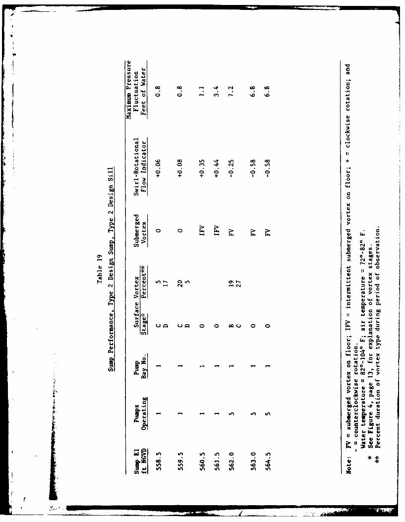
and five pumps operating (Table 18). The type 2 design sill was placed only
in pump bay 1 and tested for one and five pumps operating (Table 19). Sill
location is shown in Figure 18. The type I design sill with five pumps operat-
ing provided for some improvement in flow distribution and swirl at high sump
water-surface elevations. However, at the lower sump water-surface elevations
and single pump operations, turbulence, surface vortex activity, and swirl in-
creased. Decreasing the height of the sill to 1.67 ft (type 2 design sill)
resulted in no significant difference in hydraulic performance.
33. Baffles were placed between the submerged sills and the slide gates
(Figure 19) in an attempt to improve flow distribution in the pump bays. The
type 5 design baffles increased turbulence and vortimeter revolutions were
rapid, indicating excessive swirl in the pump column. Based on these
Q0 0 1.29 FT1.29 FT
0.-0- .-0 1.29 FT
0.5 FTF BAFFLES 8.5 FT HIGH
FLOW FL OWZLI_ \TYPE 1 DESIGN SILL
TYPE 1 SILL2.5 FT HIGH
TYPE 2 SILL 1 FT 3-1/2 IN. SQUARE1.67 FT HIGH 1 FT 3-1/2 IN. SPACINGS
Figure 18. Type I Figure 19. Type 5 designand 2 design sills baffles
28
'4"V

7
observations, this design was deemed inadequate and testing was discontinued.
34. An attempt was made to correct adverse flow patterns by placing
baffles in the channel upstream from the pump bays. The type 6 design baffles
(Figure 20) caused a deterioration of hydraulic performance for single-pump
operations and a slight improvement with five pumps operating (Table 20).
----- ------
DI1.20 E EJ 0 El EPr12. 624' l i
2.624'
Figure 20. Type 6 design baffles
35. In order to provide a greater distance for the asymmetric flow dis-
tribution to straighten, the gates were moved to the front of the pump bays.
The type 2 design gate (Figure 21) was tested for single and five pumps operat-
ing (Table 21). This design caused a slight deterioration in hydraulic per-
formance with single pump operations, but resulted in a considerable improve-
ment in swirl with five pumps operating. However, swirl was still above ac-
ceptable limits.
36. An attempt was made to eliminate submerged vortices by increasing
the wall and floor roughness in the vicinity of the pump. The type 3 design
sidewalls had vertical grooves I in. deep, 1 in. wide, with 1-in. separations.
The vertical grooves were also placed on the backwall. Grooves with the same
dimensions were placed on the sump floor perpendicular to the flow direction.
29
i F L I:t : : ": : /" "; -> '

ori
The grooved floor and walls extended 6 ft up-
stream from the backwall (Figure 22). The
type 3 design sidewalls were tested in pump
bay 5 for single and five pumps operating with
L the type 2 design gates (Table 22). There were
L Oi no observed submerged vortices; however, swirl-
ing low-pressure zones were still present and
GATE 5.OFT became visible when accumulated air bubbles
1.TFT HIGH were periodically pulled off the walls and
floor. The additional boundary turbulence cre-FFLOW ated by the increased surface roughness is ap-
_ _ _parently beneficial in breaking up submerged
vortices.Figure 21. Type 2 37. Modifications to the type 2 design
design gatessump were not successful in providing anything
close to satisfactory sump performance. The type 3 design sidewalls were
found to be beneficial in eliminating submerged vortices and the type 2 design
gate located at the front of the pump bay provided for some improvement in
.t c
Figure 22. Type 3 design sidewalls
30

hydraulic performance. However, surface vortices still occurred at low sump
water-surface elevations and both swirl and pressure fluctuations were exces-
sive for five pumps operating.
Type 3 Design Sump
38. The sump floor was lowered 2 ft to el 551.6 in the type 3 design
sump. The type 3 design sidewalls and the type 2 design gates were included
in the type 3 design sump (Figure 23). The type 3 design sump was tested with
one, three, and five pumps operating. Performance in pump bay 5 is shown in
Table 23. The type 3 design sump was free from surface and submerged vortices.
Increasing minimum bell submergence to 0.88D eliminated the surface vortices,
and the wall and floor roughness grooves prevented submerged vortices from
forming; however, swirl remained extremely high.
39. Trashracks, 8 in. deep, were added to the front of each pump bay to
straighten flow and prevent trash from entering the sump. The prototype
equivalents of the bars in the model were 0.40 in. wide with 3.17-in. spacings,
simulating the obstructed area of a trashrack with bars 0.38 in. wide and
3.0-in. spacings (commonly used by the Rock Island District). The trashracks
were effective in reducing swirl (Table 24).
40. The gates were moved from the top of the vertical drop closer to
the pump. This modification made the elevation of the top of the gate opening
2 ft lower so that flow was forced closer to the pump bay floor. This helped
to straighten flow and decrease swirl. Tests were conducted in pump bay 5 to
optimize gate size and location. Sixteen different combinations of gate sizes
and locations were tested. Surface and submerged vortices were not observed
with any of the gate designs. Swirl was still excessive for many of the gate
configurations as shown in Table 25. Gates 8 ft wide and either 3.75, 4.0, or
4.5 ft high (type 10-18 design gates) provided the lowest level of swirl. For
these gate sizes, swirl was highest when the gate was located 3.0 ft down-
stream from the vertical drop, and generally decreased as the gate was moved
upstream. Maximum pressure fluctuations for the type 10-18 design gates
(Table 26) are generally within recommended limits, with a tendency to in-
crease as the gate moved closer to the vertical drop. A gate location 2.25 ft
downstream from the vertical drop was chosen to achieve the most favorable
swirl and pressure fluctuation conditions. The 4.0- and 3.75-ft-high gates
31

FLOOR EL 553.6 91OFT~7 It
VER ICA L DROP
WALL CLEARANCE 0.75 IN.FLOOR CLEARANCE 2.5 FT
SUCTION BELL DIAMETER 5 FT
4.s
CONVERGING I- GOEN- .:o
SIDEWALLSER
EL 554.1L...E536
Figure 23. Type 3 design sump

(type 15 and 18 design gates, respectively) had the lowest level of swirl at
this location, with the 4.5-ft-high gate (type 11 design gate) slightly higher.
Recommended levels of swirl were exceeded in at least one test of each gate
design. Hydraulic performance was judged to be essentially equal for the
type 11, 15, and 18 design gates. For structural reasons, engineers from the
Rock Island District preferred the 4.5-ft-high gate (type 11 design gate)
which was thereby chosen for more extensive testing.
41. Several combinations of pumps operating and sump water-surface ele-
vations were tested with the type 3 design sump equipped with trashracks and
the type 11 design gates (Figure 24). Results of these tests are shown in
Tables 27-31. Velocity measurements are shown in Plate 6. There were no sur-
face or submerged vortices observed in any of these tests. In several tests,
swirl was greater than that normally recommended by WES; that is, the rota-
tional flow indicator was greater than 0.09 which is equivalent to having an
indicated swirl angle greater than 5 deg. Maximum pressure fluctuations were
within the recommended limit of 4 ft of water in all tests. The type 3 design
sump with trashracks and the type 11 design gates Vas deemed to have adequate
hydraulic performance by engineers from the Rock Island District and was the
final design adopted for construction.
33

TRASHRACKS FLOOR EL 553.6 90 Fr
VERTICAL DROP
SLIDE GATES FLOOR
FLOOR ROUGHNESSELEMENTS
I-IN.-DEEP GROOVESI IN. WIDE k
I-IN. SEPARATION
WALL CLEARANCE 0.75 IN.FLOOR CLEARANCE 2.5 FT
SUCTION BELL DIAMETER 5 FT
TRASHRACK35 BARS 0.40 IN. THICK
3.17-IN. SPACING
6.0 FFT
220.65 FT
o OPENING
V VERGING SEWER
ROUGHNESS.ELEMENT4 IN. WID
"EN SE. P AR5ATI
~17.58 FT
( "..
19.83 FT
22.65 FT
VERTICAL SIEALAND BACKWALL
UGHNESS ELEMENTSI-IN.-DEEP GROOVESI IN. WIDE?-IN. SEPARATION
Figure 24. Type 3 design sump with trashracks and type 11 design gates
.. ,.. : .-ps
, j .
• I i I - I - i t

PART IV: CONCLUSIONS
42. Satisfactory hydraulic performance of a pump sump with flow into
the pump bays perpendicular to the approach flow can be achieved with appro-
priate appurtenances. Converging sidewalls located such that the suction bell
clearance was 0.012D reduced swirl in the pump column. Trashracks with 8-in.-
deep bars were effective in reducing swirl in the 9-ft-wide pump bay. Sub-
merged vortices may be eliminated by adding roughness to the floor and walls.
In this model study, vertical grooves I in. deep, 1 in. wide, with I-in. sepa-
rations were used on the sidewalls and backwalls; grooves with the same dimen-
sions were located perpendicular to the flow on the floor. The additional
boundary turbulence created by the increased surface roughness is apparently
beneficial in breaking up submerged vortices; however, swirling low pressure
zones were still present in the model and became visible when accumulated air
bubbles were periodically pulled off the walls and floor. Surface vortices
can be eliminated in the sump bay by providing adequate suction bell sub-
mergence. In this model study (with a flow parameter of Q/D2 .5 equal to 1.2),
a minimum suction bell submergence of 0.88D eliminated surface vortices. This
level of submergence was achieved by lowering the sump floor by 2 ft. Gate
size and location are important in providing for the best possible hydraulic
performance. Gates at or near the upstream ends of the pump bays serve to
force flow toward the sump floor, helping to straighten flow and decrease
swirl. A combination of these features provided for satisfactory hydraulic
performance with the adopted (type 3) design sump for the 21st Street Pumping
Station.
43. Other features were found to improve flow conditions in the sump
but were not used in the final design. The large forebay in the type 1 design
sump was more effective in distributing flow into the pump bays than were the
type 2 and 3 design sumps. Swirl was much less severe with the large forebay.
This feature was not included in the final design for economic reasons. Vor-
tex suppressor beams were found to be effective in reducing swirl and surface
vortices by forcing flow toward the sump floor and by creating surface turbu-
lence which helps break up surface vortex activity. Vortex suppressors were
not used in the final design because the type 11 design gate served to force
the flow toward the floor, reducing swirl; and the increased submergence in
the type 3 design sump was more effective in eliminating surface vortices.
4 35

7
S "Guide vanes were found to improve flow distribution in the sump, but rela-
tively deep trashracks served the same function and were chosen for the final
design. Forebays, vortex suppressor beams, and guide vanes may provide for
improved hydraulic performance in future sump designs and may be useful in im-
proving existing sumps with poor performance.
44. Several baffle configurations, rounded pier noses, increased side-
wall clearance, a divider wall extension, and submerged sills were tested but
they provided no significant improvement in hydraulic performance. These
modifications have been shown to be successful in other pumping station sumps,
but were not effective in the 21st Street Pumping Station sump where the pump
bays were perpendicular to the approach flow.
36
Ado.

w
REFERENCES
Anwar, H. 0., and Amphlett, M. B. 1980. "Vortices at Vertically InvertedIntake," Journal of Hydraulic Research 18, No. 2.
Copeland, Ronald R. 1983 (Mar). "Pointe Coupee Pumping Station Sump andOutlet Structure, Upper Pointe Coupee Loop Area, Louisiana; Hydraulic ModelInvestigation," Technical Report HL-83-3, U. S. Army Engineer Waterways Ex-periment Station, CE, Vicksburg, Miss.
Daggett, L. L., and Keulegan, G. H. 1974 (Nov). "Similitude in Free-SurfaceVortex Formations," Journal, Hydraulics Division, American Society of CivilEngineers, No. HYII.
Hecker, G. 1981 (Oct). "Model Prototype Comparison of Free Surface Vortices,"Journal, Hydraulics Division, American Society of Civil Engineers, Vol 107,No. HYIO.
37A

414x 44
fa .44U
4
0 41 I*
.4-,4 to
-41
w0Do .4 -4
4.1S.
V 40(A4 -4-
0
4.-4
U .4
0
rA go
41 4 a0
41 144 4.1 4u4. 0 00 00 00 0 0 0
v 0 0
0044.4 -4 v
U
-- 54 X
a3% 04.1 .4a
U4 44 '
- 4.14 0 U 41
0 441 c 41
44 0 0 4)
Ut 41 W s
3 14 In n 4+ A A
.26L ;, .-0 C1 .0 ,-0 w 0% 0 0c 0% 0 a0C 0% 0 .M400M 0A "a in i ac I 0 i A o I %wl ~ ~ ~ ~ ~ ~ ~ ~ ~ ~ 4 ani n % n % n k nL n LIL

:3 44)-1..) CO1 C C C C 4 1 -
4) 4 (U
0 0 0
4-j)I
.r4 a DC;4)C C 88 c
4) 8Hr- 029 FZ1.4
4)
Co .0
4.)
04 x SI 4) 03t0 00)~ 1- 4J $
E-4 CU4.1 + +- +4 + + I o00 00000 41)
.0 0 c. _M .10~> -4 -W ~ .
41.m
40 CU cu
4 - -4 Lfl Wo10 wO>m ) 4.) XI 44
E-4 Q xa ii @j44))0 I r- 0% f 0 C-4-0 IA CV) M 0 M c CN V)1 CDa)4.)
4 4.) u .-4 '-'N4 C)-4 cn1- -4N I C-4 4n Cn 0 ( 1. M k 4 10a$41$4 1 = ~00
() 0 4) 0 'a 41 > r4
-4 CC k4 44 W)w) 44 4) 00.u
4 m 4., : 00000'* 0 4 0"-
4.) 4.) .".4 C3 *
o 01 w -44.4 > 00
P)'aO FA V 4
0.0. 4) .
a) u 1 4-4 4.)04 rN - - - -'C% 4N C-4 A r4 .-4 A -'in '-4I U 00 a 4
lz r o4 -ncv4)1 w .4
4D 40
to)0 Q0a.41 0 t 4
41 4- CU4
4) 1-'CI N N* N* N N '. N 4)1 w
0 ;. 4)
140 HCl)0.
410 4) 4 )~'0 W4.'I -4

41 0.
r-4 G4
X~a 4)
3t0 0400
01 0 D C D 0 0 0 0 0 - a 0 4 )0$000 00 000 000 000 0000+ + +- +-i I 4 +1 +1 +1 + +1l I -
-4 3w 0 4)
-4 r-0
41
W 4-1
$24 c0 W- 0 t
r. 000 4) W
4) .0 *to41 IT. 4)1.0
r-4 & 0
to cfl 11 t X 4-4x C:I1 4) 0
W IV4 r- cn C14 00 0 'n0 4) 4.1
.14 04 0 0 0 0
4)4 C to w 4 4)4.4 4) 0g
- to r. 0W) 41 0 04W)0 c
cn V0 '~ 000 040 <0C-C-l 0000 0000 w)tow. to
4;4 0 $4 -4
4)( 4)4.
00 3t0 6 x4.4 41U * 4
a 6
41 .0 0 0..)
~4)4
~~~~~ r- L I
i ~ ~ ~ ~ ~ ~ ~ ~ ~ 4 _____________________
C~4J 00(A 0 wWJ -4 m (
0 4 . ..)41 0) 4JjDVJ4 O! 1 C C (
-4 -4 -4
x~- P4441h
CU -
-4 m+
-4- -
4J2 'V ( DC)C f )(
0) 00 *$+
-4 c
w). 0 14 =0
r-4 4 4 AS h
~~ .,44o
4)
1.41.4 41 4
00
.r4
00 x4) I
4j I-
Mb.~~14) Oh
4. C4
:3

4) -H
= 44
m F-4 .4.0CA~-4
MA 0. >).r4 Lq
4A 0 0 40 00 'O' CD00 0C'JC' 'C'sO 00 0 Co'J\DCO O 40 . C54001
! 40 C-C = : 0 0 --'.- . 0 C- 0 c 4 e'C 'J-4-.4 6 =; aCA+ + . . ... ... . .4. .4
$C4 0 A.
04.) 0
4-I.)4) 4J
.)~~~ ~~~~~~~ .0 0 0 0 0 0 0 0 14.c 44 00 0 04 000 0 0 0 0 0 0 0 0
w) -4u - -4 P4 -
$-)
-4)-
4)4
4) 0 ). 0 4J0I I i i 0 0 ~ ~ 0 0 0 I
.00~~ 414~S~ >~Ig -o 4-1
1-0- 4-4 $-4-4 4
0) 4) 0 4).0 4.04 O j CA0
:3 a1. 14 4f4AW04 n ) 0
40 .~l p14.14$4 to0
4) a ).
0 0 4) "4
4)4) 00- 0 WaI 4U oL 44.44)
L.0 $4)0000(.) ~ ~ ~ ~ ~ ~ ~ 0 00 000 0. 0 0 0 ~ 0 0 0 ~ I0
4)1.
.-4 w 4)0
a 000 44be
01.4 'm .M en i LM L00 W 0
4) - 3
0 CO 41 CO 41.4 wA 4)
1..4C 4) u.
r.) 14'X Aw4)
Wl4) L
Si0 0%i Sfi eqS) Si rin4 kn s s
.4 kn km fi-$4.L M n

W0 l41
4) .,4 to
Z' 4.141a 0 0
04-4
*04.
-14
0 -
00
040
(a 41u
0i 0t0o
) -4)
SI "'441 41
0 tU
00
4) 00 41')-4 0 cc
0 CC W
4j~~~~r 4) LM ( .4- DmQ4) N l 4N 1101
S-a ~:r 0 40
(N 004) 4 l0 04
0FA'1 0 4) 0 0
u2M 1.M 1,4
to 0
0 EQ 4
E) , - V 4) 4
00' $04) 0
".41 001
'-41
'A , 4 a 4 4to L1
41Z0 0to'.
01 P.f j c4

m r
44tot ~ . 0
-) 4 $~"4
0 00 '
W ~ 40 0to -M CN- 14 C
0 =
4 3C)
44.4 -4E4 4 o
04.0
100
4V 00 0 00
.0. 0 0o 0-04o* > 4 41I
4) u - (... 0-4
41 1
0 &a 000
$4 0 0 0
Q) 44 w 0 4
44 0) 4) C.r- 4 +4 4J )0.
4J 4.J -4 4 -W$44$4 M C
-4 4 44. 10
CV 4) 4 10
0)0 CA0 14 X )4U
Ln Ln L in I' 0 4
SO41 '0 0* 04) 41 4 4
12, -4 uV 40
$4 4.)
-.4 4J 0 ~4m C3
r.. 41v 004
4) U-4 0
Go~
In in %C %Ij In 4n in
VO4

U3 4
U044' 0.V.41 0 C -
x P-4 V iV+
-4
0 41
-20.4 M x4.).U
0 0
-44 00
41)
aj' to 00 ii 1
k0~4 ~P4 4 4 ~44 k kk 54 -.4~> Ai 4 4 a. .rJ 4.3o 0
4. 0 - CA>
Va 0 mca
m rA CA 0
uJ. C'4 CN. C- C1 *.+ S.' 10
0 4) 0 V 4.) > a
4) > P4 0 = to
44 'A 0 0 ) 0$40 .. . 14 1
4J 4J -,4 9V0 h 0
0 > Q'44 V~ax
$4 VCA 4) 4
o.' 00 00 $haCI a m 0 41
in LA LA LA e.C1 ITLn 4 m C-T Ln 00 ha
4) 11 4
41 0 0 0. 04j U 41
,4
m 14 n Le)Q 1 )
-4 4J 00 44
0~~ ~ c.CJU~~~~- sAA '0 ' '. . .
LA~~~4 vA L AL f
~4 4J-
VQ
WO 0 4 0
m.4 c CJ %D C1.4 0D
:3 4441 0 0
0 41
-4
030 0"-0 4141) 4)
4~~t .140~R om I 0 0 0
3, + + V .0 4)
-H -400
4) V)
0 0
CCO
4) w0-00 >( 41
C4 0 w41
0 r4)'...*4 I004w
cc~~~~ 0 10U I x
4) $Ww 4 04-)00 4.) J> ,
>- el 0 ccrC4 4.C $4. C'4 4)4(f
4) ) 44 4)h 00
0)0 4) 0 C:
4) $w :
00 U000)
V.4 0 u 404) 0
Q) 4.1 4.. . 4 1
Z. %D1 1 o 0
4)0 04) wto c
41. 00 ~124 0-A I.Z C34444
-44 4J00 4O
0 4 C:
4 14) '. w
Go. 00.044.) 4In %a
n LM LM In %n In
cn~
-j----------)

W 0 4 4)
4) .,4 mU
0.4 cc -4 cn 00 00 0) CN z
0. 0 C 4 C
-4 -4 - -
' 94) 41
4) 41
C: 0
00) ~ 4C.. U ~ ~ ~:
4) m % n 0 00 0
-1 10 0 '4-4 -f
0 f tAIcl~ (
00w ' ( 0* -4
-O '4I', 0
~nI$4
4)04
$4
?A 0 4
'0 00 0 0 C14 00 40C.
-. 000c 00
:33-,4 r-4W
0 00 0
(A 4J.) 4)M, H, c'n 11 IT 0% 0 0 -4-)'0 CJ - -' '0 Lf) - 140 0 oX -4 0 0) 0 >I43 + +9 + + + I
10 4,-4 r-4 00
(A2
4,
0. aCaA k l
4, 0
4, 0O 3 w
'v-%0 w z 'I 0
11 X) 4, 4
0 045-0E- )W 00 Mo f C) *4 0 04.)
~'0 ( 42 0
04,m 0 *4)to--4 0 w- 444
.4.j 4 .cc I r 0
44 0~ 41 4) 0 04 0 41 -4 4
4 r oC) 0 1 C 0 4,00 m :-Ir 00I. I-'1-0 r-~I4 4 4)
00 u~ 4(U4 00
w 0 4
0M4- 0 1 -
4) 0
4) 0 oII $. 4 Q a4 4
4~-4 4j 1 j .,4
4) A -4 1 t
04 r V

$441x
t*$4 0
C: 01.
-41
cc .010 Q $
04 )- C(U +U
CU*. CN 0 0VA r .
m 0 a0
. 1 -4 (A0
41
cc .0.4 4.1
W. 0
41.
>) w
4)~~~~4 04441~U)~~Lf (A4 > 4'4 ~
co .00 S-~I
Cl) 4) 0 '(-~. m1'A
4) 0 a r 00).C) 4) u. W 0
cc $4$40 (UV
3- 00 U) C
"a 4-0 41
4) 4) 44 1404) 40J ".$4
m0 0 m. E. c.4)0~( $4 0r' - 0 $4 4-4 .4
cc 0 4.)
0 4)0"a.u4)04 4-) 00 4*
00 -$4 0.w x00C.)~ 0 00~0 0 4) 4U
4. 4) - 0%0U (Y) >
0~ 1144
0 4) 0V
$4 *004 0 . 0404 4 1 -4I 4
to2 O 41
U 4)0ce~~4 II $A L W t 4 (U
11 .4 wW .4
044)1U34 4. 0 4
0 4
4J4 U
gn $4

L4) L
UA 0 41 0
4J .4 0 1 C4 C ': 44 if1
41t 0 - - - -
4144) 10
0 0 00 4
m mU 41 a 0) C) C) CY4>U wU 4J 0 0z 0
4)I + + +- + +
.14 0 $40(A CU -4 0
41)
00 40W
0 -43>. 4.)
be1 41 1 ON w
-4 C: r- -) wf
9.2CC' 0. 0 C
E l O) 0t in 0' '0 '04.
$4 'A wAL zA0 0> 04 02
-4 _ _ _ _ 444 4 0O

44)
r.~4 0C: 0 41)1ac.,4 MJEn( 0: m' H CN %0 0 0 .
w 41) 0 a '0 40 a ' a CD
4) r4 4.)
C:. -- 4x
w 0 00- 11w. U 4) >
-4 (U.4 c(4 '4 - '0 0 -
0 4-) 000L:3 >- 00 0V.0 0
be 44 4J0 >r4 a~X 4.4 $
=U U 4) 0 4J
41 -
11 X 0 4.
E- 0Gi i %0-IT -T r 4) 41 ) ) 1
W4 54 .,4 +1. Z 0-0 ai U1 >0~ I00
> (UU)40 to .
C~ -4 44(
40 0 wl .0 .-(U w) 11 0) 4 )04
0444 0s . I'- ('3 4 1 4.3 $U). 41 -.0 00 4 41~ W m =
) 0 4.) 0 .m-9z .> 0 1- 4
0) 4 4 4) 4140)4)(U m W0 0 .
U3) 3t.4 f $q (C ar 0 (
4-4 1 64 6
I. 4.) CJf(U CCC. V4 ) n V 0 0 a'4. w4 (4) 4 0 -S ' 0(U
0 4.Ju
E q-404) 404.
4) *-4 (U :1120 -
M4- 0I. s. 'I
-44 0.M -0
law4 CCI 4)1 41 .4
0.1 Do 00 w 00
114 4 0
1.4 t 4 (U w.
4. 00 'V.4. "4
41 0 n n Le04.1in004.l

4) -
Ad m 4 40)4C1 4 0 %
") 0
m. 4+
934 0 0 0' ' N -7 0 \
- 4
Xu& 4)
., 140 % I0 C: 0
"4 3t 10
4 0 0W+ +4 to I I
Ct4)
U) .
4) 4 1 >
q) 41 44.0 0
4)C* ?A4 > . 4 .4)a.5 co wZ. 0w ~ .
.00 0Z4 4
4) 43 0D (
m4-) C CJ) 0
W ww 0401
"4 0 w0044)
4) 44 A0 ) 0 M
m cc4)I ) 44) 0A. C'1~ 4) 0' C. :4)
0.5. 41 41404 0 41"
u~~~~~ ~o 5.4C 0 Wwm:
a) 0-" 400
0 > m 0, 004.4 04-54)041
4) X4) 0 .54 ITw
-4)0
0:0-1 Ou 4)4.014 4 4) 04) 1 I 0 4 to 14a0.411 U 004)0
14)1 41 4
W -r v 2 12 M 4 0 1
asl 4.411 P 4)
"1 4)
co~4 0% 14 m1 C
14.)~451. "4U) In i M ) L

0.) .- 4 IU -x. 944J 4
4.O -7 ~.0 0 0
m- -4r- C* )4.) "a0 *
-4
-4 00
0441
4)a) >0>A
CI..4~rZ 0 r- c Ce4 -. 8C .
-t Q a . m
~~-4 0o 0
1.o 0.)1.
$4 OCX 0.004) 0 > .>. 0 m -
W0 r-4 sZ4 54 I3
0J 4.4 4 0 C
x cc C 00.r4 0 C6
00 0 0( U
00 -4 X4,Cu;9 x4X )
00) 0 4* x.w cu 0 4
-4 4 4. 4 41
I) W 14.4 0 .0. 41 )
4-4 ~ c 0C ~ 04) 4 .) 0.
FA -. 4 M,-; (
U0 ) ,4 0
06 40) 0
0) 4 60.4.0* 0 .1a
A4)4
4 .) 4 s
-q cnio
-010
.4a;~~~I c.4 asa 01 C c TLn~~~~0 Ln % a . ) C441 in Ln Ln Ln V) kn 0f)

4 m
4) *4 X Go
41J -0 -4 . U C J- 4.)-
-. P-4 4) >C.0
4
04) I
mO .1- 4 '-4 CF) r- cn I&0. 14 ( 00) j a0 40 C0 0*.4C 4 C4 1"
0 - 0 4-004 41 .0e'i.-' 0 r4 w
r-.~-r 4)4) X 0
00 4.-., .4)be w- 4) >4 -4.0.r 4.) +~ -l
ca S 0 >u- A4 .04) A0 It 0 4)40>-) -- 4 ,4 .-. 4% CJ1 ' ~ -
4)4) ~ ~ ~ ~ ~ ~ ~ C uJC -''. LAO0i L r ' L? JM4.00 00 WO>
04) x 0 Cho4)4) + . 1- 0
01 0X 4)4-44-441 40W > -4 x *
c 4) xC 0 m0. 4) 400u. '4) 4 CN C)nONQa n r CD- -10 a: w41
41u -0- 40 S 4 C)c :3 $.4 '0sd 1w .) C- $4 cc~0 ~ 0 41 0 00~~ W w0 >-,
>l A1 00 w w
44 4) Is 44) 4 00
04 44040 410 W.0>4 -4 ,
0 a 40W
O. 4-4 CO w0301 4 41
Ln Lt) LM Ln - N mJ eq - n 0 3 .
4) 0-
41 I 4 -14
0'- .- 00a.
410 :3 04)
U3 A 00 $40 -a0 M. .
If1~~4 IW LA LA L
to _ _ _ _ _ _.
- H 14 W 4U
) .-441
1364M Q 00c C14 0 C4 00 CN Cq D o c i ejco C 'J
P-4Q
cJ 0
m _4 00 0c -- 00 0 00 .0 00 004i)00
3r 44
w ) .4 44444 ix+ 444
.O 0 4L Z.:X &4Z:4X t >& 3 > r z >.R F"t
0
44.
14 0)4) -
4)
04)Cun
41
00 0Ln 0000 0000
-4
C*4 crb -%D %a0N
41 Lnul nV

1.4W
(A Q41)4
m t a. a 00 -4 It0 It Q7J0 'D fD co C00o00 4 0.
e.43 4-) L41J
x z4 4 j0
~00
10
.r4 M 4-
cc r4 00 C14 0 C'.I V) m ~'.OC14a C J0C 7 C1Jui -T Le) It T to
0~ 0c;C ' .40 0 D,0 D
WU *-4 3C4 0$4 0r4 v
(A
'41
Co x >E- 1 41. +- + 0 FA ... .- 4-M4z. ~zz+ za4 C:
a acu4 > "> :t-.0 Ol P4 4 4 -4 w 00to -4 4
.0 u co0 w -00 LU 0I1 00 4J
r.L C0 4a CA)60~ 0 C% 41 m
4J .r4 %. Wi 1.'D (0- CA r. 4)@
.0 0) 4-J . Gi 04-. 4)) ND L(I It 00 Jqff C ML 4.) 0 4
4) u 4 C4 04 -H401.4 4 '0
q; 0 U4.
41) 14 414)4) 1 4j00.
) 4-4 wI o r.0u s. 01 0 4- 4 "r493 LU t 4 4.
Q Q. an- 0g 00000C jwm:
10 0 1-4 4
44 4. "4 ;;: 1' K:r-4 M 00)
co 0~ 4.4)
C,, 0 f- - 0
4-440C~
4)1 000 w 00> + W 1-(0 L
(a)L -M4)-
a LMLn 4 3t0) 1.3w $14 V4)U 04.) :34
0 4 b4
110)0) W
If)~~ Wf Ad f 00.
I 000%r 0- (4~uLM it) %Z so0 %0 4
41 ifM In) &M in) i) ifM 0
CA 0 414) -4 C$4 41) 1
ow t 00 00 'T. C'4 400 00 0:3 -4 4
41 0 0 041w' . '.
:3 04- 4-1-4 r-4 4) 0
00
Ii 44J
CO H Z 0 ) It7 Vf 00 00+4. 1 D CY) -t LM. LM u
1- 0 0r00.
00
U) 0
C4
4) 4) 04)4. 0 >
> >. 0 4.)
Q 0 00 -.0 > 41 i
-- 0o (A >'
.,4 41 0 0I
U 4 1 4) X)404)4 r. N OiA O'.r 4-) 1.
C4 41)( u C'.4 = l 10~
04)0
%04)1ci 0 1 .0
Q~a 0 0 co Q 0 0 -M "404j9: 0Vcln
0 *4'4-41.4 04) 0 04) 41
r-04 l'4-4 " 4 0 1.4 X
4 ' 0 4)m 1 44 41
*~~ -1 - 4 - -00 S..1 oej-- - - C1. w 0 (41 V
v)4J 4 4)i 11 4-w FA 4) 00" -H)t 00
4) m 0 4.
cc4. 1 u 41 1.4
0 40 0 to 004.)L40 r4 0 14 -4 m)
w J4) 1.44)i 41 4)
51)~~ ~ to1 S) 0 f
41 $
ao 47% (4 -
CI2'%A4'.a40 ~c4

(A C:4ca a 0 4
4) .14 m~
4) 41
aj 4)
4
4)1C.14
C0~ 0 00 00 00
1.414)
-4 0)C04-4~ 0-4 CCO
0 '.4 *4.-4 4 -4 = 4t (
-n C3 -- da, U-4 0 4. 0.
(d, 0
w26 2j>>>>. - -
I w~ .. .. -.;& . > )-4

8G ='4 4
-4 r-4 W t
CO4- 04)1~~- $4 C
CUI.4
*4jI u -4m .14 ON ur) C 0 0 r-- 0\ O C Dm CY I? C)r- I~c'NCN a c m
(A *j' - 4 0 a Cn C14- T 0C) nC1 -TIr-4 r-4 ,4 4 -4
4) 0 0= 0 0 0 0 0 0 .
*g + + + + + ++1. +++ + +1+ 0 +1
01.40
v.44- 41
4- U,
C) v.4-.4
C14
1.IC)~~~~~~ 00 > 4 4..4)~ .- ~4j
4. . cl 0
'- 4 U) u 4 4 W'
. ) 0 4) >. I
aj 4) 00
C-i C:J q) 0,40 .'14'C: 41 4
4) 04) 4
3t 4m 0 4)93 w ' 44 -
0) II) Ln 0)C4m1 n Nc T ) C4m- n 0 0 w
10. 0 0000 000 00ridC X r4 en >
444
00) 004 U) 0
000-.C: 4~)U -4to 4
(a LnLn Ln4) 3t 4.4:
41 0)
U3 4 93
''4) (u u4j 4j) w.
S0 CS 0.-
00~1 asa -4C4(
* 4J4.CA 44

:CA 0..QW 0 40
W ., m
0. -* C1 -N IT-(V
x P4 4)
CA
ac 0. 0I4 0 0, 00 0 0
4) 41 +1 + 1 1 +-f4 00
10 r.0
3 -4 4w 0
E- M)3t
-)
cfl $4 4)W)J 0 0 0 0 0 0 +1 0
0r *$4 >
00 4)cn 00 a o
-i On4j 4w 41 oi 0
E-.. x C3 4) 0
4)- 41)( M L 4) 41
w $ 0 00
0 - ) 0 4 )0.-0-> 4)4 OC U4- ')r 4 )
$4$ 4.4 4)
* )0 $4.
0 o C0. 2 a004-4 qt w- 40 0
U)o $4 4 -r4U201~~~~ 41 w.~~J 0 0 0 04$0
1= 0Q C 0 041 41~ -4) -
140) 4
44
0 1Q0 4)0
0 w0 0$a
:30 01- 0
41 4
$4 01404) $4
041 4. ,41
0 4)0.4.
~$41
LM~~4. 0Ain4n 0 )tco CA *0 li c
&M ~~~ %ma %0 %a %In~~~4 In In LM in in L

4 4
+j) 0 -iC
mm
r~4 m)
4.) QCUm -M O C4 ON e. % ) Lt) I
0I- 0=I + + + + I I I I I
1.40
00 xG41 0( 0 0 0 0 0
. 0 4Aj I
0 r-4) C-4
-4i10 4; a1
0 ~44 4.J 0 0) 04 0 0 0 044 14 $4 u C:
1.3 ~ 0 $
0ad, ad, kn ad, Ln Lf L Lfl Ln Ln V -
o cc41
a4
.d
u 40
0~
P-44
II 41A

(A~ 0 4 J
Ga ;A4 (U
- -1
m O 00 4 C cy) 00 Ln r- LrA CN. 0 -D .- 0D 0Co C' C'J 0 (c0 C34 0 0 0 0
-4 3 + +$ + + I+ + + +
4.)
.00 .6)
.0 coI
"-4.
Gau xm44.- 0 0 0 0 0 wa44 4 4U
u C> Ga)93 4- 4.)
0 m
S0
"-4
-~~~~4 - 4 ( (C A AL
04.w
US.
II 4)
Cz3~~~~~~ LAL ALAL1ALA 0 0 LGOO%0w40'4CJC 1~ 4S
00 4A L 0 ' 0 '0 '0 '0T0 '4.) %n LM Ln LM LM LA Ln LA V)

X4 4) 00L)- n c4&no o% - 44) TC 4r o - 0o~cu 000 a-CD00 000 00040-
E- nC14
(U4 C0 C1 . 4-44)04 ) Q4 .4 JC-40- 4 I0 C'cj - QC -4 4. (D 0 14 C D 0=)~. 00 0 .'4 ~ -.0 0 0 0 0 0 0 0 . LnCD .
14
cX ON t~' 44.0 N.t .
S I44 r-4 c4-4
acL) o-4X- 000 a '-,40, 4 X t) -4 0000 0 Q(D0 00
C- 0 0 C-' C4 4
to 1. 4)I~C. 0 4 ) 4.C)C4C - T nNC44 4 0010MC)0 0 0% -C)0
., xr 0 4.4 a04 Q DQ0 D0C DC
to 0E-4 In 0000 0000 C; 0000 00000 0~ 4.) 0E-4 C14E-4 0 4
In 41 I '4
w. 00 44 .- 4 '")4131 -'44 CN C) 00 C - wx 00 c'or.'.o' 0~ C14ei ' ~ .0 C) C) a
m C-' 0000 000 CD c 0000 0000 a4) C
.,4 0W ' 4)C00 4- 41
co 004-4 " 4.4) 'o a.Ln n ' V4) en X %Q Le)-4C *4.o C,4 l cn'%D
C4 . 00 0 00 ~. . 00 0 00000. $4) aD 400 4-40 )0 ; ;4-a C 4
-4
4J
cn~~ 41)c - 4 1 4)
to 4 000 -0 40 4)X 0 r 00 0 -400
Ln C &-4 $ C4.4 .,4
4C3 4)
41)0r-4 cc.4U
39 41 4 -4 4-4 4- C"C4 UI- ' W4-~ 4-+- : v~
0
0
-1 Leni LI .1 0w! nI w! w? aU,0C!&wV O 0%0-0 -4c~cn* Comoa40.- -1e'acn ?
W in -n %CD %a %0 10 %0 0 NO A In%D NoNo % %a.%* O%Dc I4 n Ln %AIn tn IF n n nin w wU)M'Ann I n ln %n In
4-

00
-4 X 4.4o)L ) 1 ' 09 C'J 09 '9 C.J 1"! 09 119
- - C-4 C.'4 0a -4 14 -4 1"
'-4
M I-. 4D9 4 4 -- C
E-4 -
.14 0
41 Lf 4-j
4) -100 4.4
4) 00 V0 '.9 '09 0011 '.0 '09Ci -4 -4 -4 -4 CN- -4 " " C-4 40
.4-)
0 4.)
>14) WUs 4)
4) $ 4f4 .R.4.4
,- )-4 .
4) 4)4X
44)
.,4,
Cr. - ~ *4 00 4j1-X 44 m
0 A4 E- -04
0-4 1.4
4.))
- Q- C(4 C
~It cn44% 4)
a)a
0 .4 .) .4 V
4J4 4) * )
v 0
4-4 4--10
r- 4 00 -% 0 ~ V-4 C,4 If4 ) LLn 0 t- %0 %0 %D %0 0 NO %
4.1 n inLn n Le Ln m % LM M 4

Table 27
Sump Performance, Type 3 Design Sump with Trashracks,
Type 11 Design Gates, I Pump Operating
Maximum PressureSump El Pump Surface Submerged Swirl-Rotational Fluctuationft NGVD Bay No. Vortex Vortex Flow Indicator Feet of Water
558.5 5 0 0 +0.08 2.0
559.5 5 0 0 +0.03 2.4
560.5 5 0 0 +0.05 2.2
561.5 5 0 0 +0.02 2.0
558.5 4 0 0 +0.10 0.6
559.5 4 0 0 +0.06 0.6
560.5 4 0 0 +0.05 0.4
561.5 4 0 0 +0.04 0.4
558.5 3 0 0 +0.08 0.6
559.5 3 0 0 +0.04 0.8
560.5 3 0 0 +0.02 0.8
561.5 3 0 0 +0.01 0.6
Note: + = clockwise rotation.Water temperature = 850-900 F; air temperature = 80--87* F.
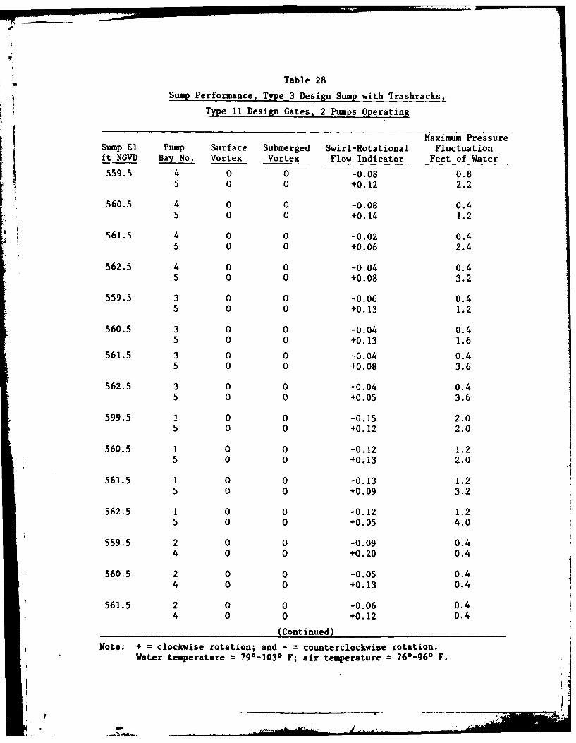
Table 28
Sump Performance, Type 3 Design Sump with Trashracks,
Type 11 Design Gates, 2 Pumps Operating
Maximum PressureSump El Pump Surface Submerged Swirl-Rotational Fluctuationft NGVD Bay No. Vortex Vortex Flow Indicator Feet of Water
559.5 4 0 0 -0.08 0.85 0 0 +0.12 2.2
560.5 4 0 0 -0.08 0.45 0 0 +0.14 1.2
561.5 4 0 0 -0.02 0.45 0 0 +0.06 2.4
562.5 4 0 0 -0.04 0.45 0 0 +0.08 3.2
559.5 3 0 0 -0.06 0.45 0 0 +0.13 1.2
560.5 3 0 0 -0.04 0.45 0 0 +0.13 1.6
561.5 3 0 0 -0.04 0.45 0 0 +0.08 3.6
562.5 3 0 0 -0.04 0.45 0 0 +0.05 3.6
599.5 1 0 0 -0.15 2.05 0 0 +0.12 2.0
560.5 1 0 0 -0.12 1.25 0 0 +0.13 2.0
561.5 1 0 0 -0.13 1.25 0 0 +0.09 3.2
562.5 1 0 0 -0.12 1.25 0 0 +0.05 4.0
559.5 2 0 0 -0.09 0.44 0 0 +0.20 0.4
560.5 2 0 0 -0.05 0.44 0 0 +0.13 0.4
561.5 2 0 0 -0.06 0.44 0 0 +0.12 0.4
(Continued)
Note: + = clockwise rotation; and - = counterclockwise rotation.Water temperature 79°-103* F; air temperature 76*-96* F.
- t

Table 28 (Concluded)
Mkaximumn PressureSumnp El Pump Surface Submerged Swirl-Rotational Fluctuation
ft NGVD Bay No. Vortex Vortex Flow Indicator Feet of Water
562.5 2 0 0 -0.05 0.4400+0.11 0.4
559.5 3 0 0 -0.09 0.44 0 0 +0.20 0.4
560.5 3 0 0 -0.05 0.44 0 0 +0.13 0.4
561.5 3 0 0 -0.05 0.44 0 0 +0.10 0.4
562.5 3 0 0 -0.04 0.64 0 0 +0.10 0.4
(a

r
4 Table 29
Sump Performance, Type 3 Design Sump with Trashracks,
Type 11 Design Gates, 3 Pumps Operating
Maximum PressureSump El Pump Surface Submerged Swirl-Rotational Fluctuation
ft NGVD Bay No. Vortex Vortex Flow Indicator Feet of Water
560.5 3 0 0 -0.05 0.84 0 0 +0.04 0.85 0 0 +0.08 2.4
561.5 3 0 0 -0.05 0.5
5 0 0 +0.08 2.6
562.5 3 0 0 -0.06 0.44 0 0 +0.06 0.65 0 0 +0.05 2.2
563.5 3 0 0 -0.05 0.64 0 0 +0.05 0.45 0 0 +0.05 2.4
560.5 2 0 0 -0.11 0.44 0 0 +0.02 0.85 0 0 +0.07 1.4
561.5 2 0 0 -0.08 1.44 0 0 +0.01 1.45 0 0 -0.04 3.4
562.5 2 0 0 +0.11 0.44 0 0 +0.03 0.45 0 0 +0.04 2.0
563.5 2 0 0 -0.12 0.44 0 0 -0.05 0.45 0 0 +0.04 2.4
560.5 1 0 0 -0.11 1.44 0 0 +0.05 2.65 0 0 +0.08 2.0
561.5 1 0 0 -0.08 1.44 0 0 +0.04 1.65 0 0 +0.08 3.6
562.5 1 0 0 -0.04 1.24 0 0 +0.05 0.65 0 0 +0.05 4.0
(Continued)
Note: + =clockwise rotation; and - counterclockwise rotation.Water temperature =840-1050 F; air temperature =76*-97* F.

I
(Table 29 (Concluded)
Maximum Pressure
Sump El Pump Surface Submerged Swirl-Rotational Fluctuationft NGVD Bay No. Vortex Vortex Flow Indicator Feet of Water
563.5 1 0 0 -0.12 0.84 0 0 +0.07 o.45 0 0 +0.04 3.6
560.5 2 0 0 -0.11 0.43 0 0 +0.09 1.44 0 0 +0.16 0.6
561.5 2 0 0 -0.08 0.83 0 0 +0.03 0.44 0 0 +0.12 0.8
562.5 2 0 0 -0.09 0.43 0 0 -0.02 0.84 0 0 +0.14 0.6
563.5 2 0 0 -0.10 0.43 0 0 -0.02 0.84 0 0 +0.16 0.6

Table 30
Sump Performance, Type 3 Design Sump with Trashracks,
Type 11 Design Gates, 4 Pumps Operating
Maximum PressureSump El Pump Surface Submerged Swirl-Rotational Fluctuationft NGVD Bay No. Vortex Vortex Flow Indicator Feet of Water
561.5 2 0 0 -0.08 0.43 0 0 -0.03 2.04 0 0 +0.03 1.25 0 0 +0.06 2.8
562.5 2 0 0 -0.13 0.43 0 0 -0.03 1.64 0 0 +0.08 0.65 0 0 +0.05 2.8
563.5 2 0 0 -0.13 0.43 0 0 +0.02 0.44 0 0 +0.08 0.55 0 0 +0.05 2.0
561.5 1 0 0 -0.09 1.23 0 0 -0.02 0.64 0 0 +0.02 0.85 0 0 +0.10 1.6
562.5 1 0 0 -0.09 1.23 0 0 -0.04 0.64 0 0 +0.08 0.65 0 0 +0.04 2.4
563.5 1 0 0 -0.12 1.03 0 0 -0.05 0.84 0 0 +0.09 0.65 0 0 +0.05 2,0
561.5 1 0 0 -0.08 1.62 0 0 -0.02 0.44 0 0 +0.05 0.65 0 0 +0.10 2.8
562.5 1 0 0 -0.09 2.02 0 0 -0.02 0.44 0 0 +0.07 0.65 0 0 +0.04 2.0
563.5 1 0 0 -0.14 0.82 0 0 ±0.01 0.44 0 0 +0.05 0.45 0 0 +0.04 3.8
Note: + clockwise rotation; -=counterclockwise rotation; and ±=alter-nating rotation.Water temperature =94*-105* F; air temperature =800-94* F.

Table 31
Sump Performance, Type 3 Design Sump with Trashracks,
Type 11 Design Gates, 5 Pumps Operating
Maximum PressureSump El Pump Surface Submerged Swirl-Rotational Fluctuationft NGVD Bay No. Vortex Vortex Flow Indicator Feet of Water
562.5 1 0 0 -0.07 1.2
2 0 0 -0.05 0.4
3 0 0 ±0.01 0.6
4 0 0 +0.04 1.0
5 0 0 +0.08 1.2
563.5 1 0 0 -0.12 1.0
2 0 0 +0.02 0.8
3 0 0 -0.03 1.0
4 0 0 +0.08 o.4
5 0 0 +0.08 1.2
564.5 1 0 0 -0.11 1.2
2 0 0 +0.05 o.4
3 0 0 +0.02 o.6
4 0 0 +0.03 0.8
5 0 0 +0.04 1.2
Note: + = clockwise rotation; - = counterclockwise rotation; and - alter-nating rotation.Water temperature = 890-960 F; air temperature = 860-910 F.
.................................

F fF
• • I U i I S , UII
1.[a2 .8 1.3141.5 / 0.0 l.1' 9 1.21,4 .8 2.0
07 1.6 1.41.2 0. 09 1.1t It ,-. .,1' * . * t t 4 %r, .0' 'u•g ' S . .3.1..23.3 9 1. 1.4 1.21.01.0 1.2 1.44 32!,
0.9 1 1.0 -
a9 ae, 8
Aa A A .b # 4 n
i4 i3 1' 1.2-' I I
1.2 aI 1.4
SUMP WATER-SURFACE E L 562.0 FT5 PUMPS OPERATING
2. 0.2 1. *
t '16 2 2 1.57' . 142 1 8 ' f 294P6
I /t~at"'~ 10.7 ll
LEGENDI*. MEASURED VELOCITY, FPS
-- ----. F LOW DIRECTION BASEDON DYE INJECTION
TYPE 1 (ORIGINAL) DESIGN SUMPVELOCITY MEASUREMENTS
1.25 FT FROM FLOOR
PLATE 1
rr 4

o. .1. 0 8 o&'a8a 09 '0.6 06080-90076786.00077 0000
14£ &9 A i.14 f E.17a8a a39,0 a 4l50.7 6 081-0 s 1 7 0.6f 0. 0 .8a7
2.2 _0. 1 1 .502.71 1 . . *I It, £ -A I a7b o. 0.51.6~
It t itj * f-ta0t '
~~~~SUMP WATER-SURFACE EL 560.75 FT M AE-UFC L585F3~~~~ PUMPS OPERATING 1PM PRTN
LEGENDA
1.51.5- 91 .25 FT RO FLOO
PLT 2 4 f-;
7 1__ _ _ _._t 1 4 4 0_______;2.
a
ag Y~ 0.9 1.415 7 .9,l 4 a
S -0

f
017
01.14 It 1, 4O6 t .21 07 f f 0 9 11090 t'6 2.j ~~~0 08. .6~ '
.1.81 I pl'o1.7 J09 0:~0t~s{,~o u t 1.9.2.a8060.7.1. . . /a 1.1
0. 5 O'1l1 ;I t 6 4 .7 4 t 4 10SUMP0101 WATER-SUFC EL56.0F
5a PUPrOEATN
1.7 1, 16 1.42 1. 10 1-SUMP WATER-SURFACE EL 558.5 FT
PUM PUP OPERATING
LEEN
1.5 TFR.FLO
PLAT 3
.0 'p+ 22\

V
iI
2120 21 21
t922 131. 1.7 2~21.2 rn
2.2 2.1 . 22 2.21 2.3 1.4
(, ; ,
1 .9' 2. 0 ,-2 . 1. I 14?'~~~ 4 4' A i
1 2.12.2 12
TYPE 10DESIGN++
GUPEIDESIN TYPE 2 DESIGNGUIDEVANEGUIDE VANE
i " LEGEND
2.? -Z 4 -?a 29MEASURED VELOCITY. FPS---... FLOW DIRECTION BASED
ON DYE INJECTION
21 2.2 22
It I ""
1.92 1.7 1 ]
VELOCITY MEASUREMENTSTYPE 1 DESIGN GUIDE VANE 1.25 FT FROM FLOOR
TYPE 2 DESIGN VORTEX SUMP WATER-SURFACE EL 550.5 FTSUPPRESSOR BEAMS 1 PUMP OPERATING
PLATE 4
|so

NO. 5 NO. 4 NO. 3 NO. 2 NO. 1
.3 .3 45. 1' 2 4 -4. 3.1..1'",i
6, 1.4 5%- 147
; ::: ,I ',, : ,' ! ' ; " ',, , ,A , , i /' -
• " II\ ' \
S'.5 ,If , , 2 5A it
SUMP WATER-SURFACE EL 562.0 FT* 5 PUMPS OPERATING
NO. 3 NO. 2 NO. 1 NO. 5
.1 12 a7 a
2-1 22 3. 3.4254~~15 t 22 1. +r33 ~l s,+123 124 + *
26 ag a . A~'
I I! It,.
-------- -------- ---------
,,,,i ' " " ",
/ " SUMP WATE R-SURFACESUMP WATER-SURFACE EL 560.5 FT EL585FT
3 PUMPS OPERATING I PUMP 5 OPERATINGI I
LEGEND
MEASURED VELOCITY. FPS
--- --- FLOW DIRECTION BASEDON DYE INJECTION TYPE 2 DESIGN SUMP
VELOCITY MEASUREMENTS1.25 FT FROM FLOOR
PLATE 5
,. rF " .. I ..- , .
__ ' If I : I

NO. 5 NO. 4 NO. 3 NO. 2 NO. 1
73.0 4714.1 -. 17.a7 3 0 3 aI13.6
i',; f lu ,".;
SUMP WATER-SURFACE EL 562.0 FT
5 PUMPS OPERATING
NO.5 NO.4 NO.3 NO.5
293. 3. 4 .0. 340 3.~29 8' 4.4 #44 3. *
I I I I
i i
SUMP WATER-SURFACE EL 560.5 FT SUMP WATER-SURFACE EL 558.5 FT
3 PUMPS OPERATING 1 PUMP OPERATING
LEGEND.MEASURED VELOCITY. FPS
....- FLOW DIRECTION BASEDON DYE INJECTION
TYPE 3 DESIGN SUMP
~VELOCITY MEASUREMENTS
1.25 FT FROM FLOOR
PLATE 6
S W A T E R -S U R F A C E E L 5 . 5 F S W A E R S R E 558 .5 F T
.~~~~ PUMPS OPERTIN 1.. PUM .. ."P...ERAT:I- :I I ING