Actuator Operating Manual - Intelligent ActuatorMJ3606-15… · Safety Precautions (Please Read...
61
IS/ISP ISA/ISPA Actuator Operating Manual Fifteenth Edition
Transcript of Actuator Operating Manual - Intelligent ActuatorMJ3606-15… · Safety Precautions (Please Read...

IS/ISP ISA/ISPA
Actuator
Operating ManualFifteenth Edition


Note
Lubricating Actuators of Clean Room Specification Use low-dust-raising grease for clean room on actuators of clean room specification. The grease brands specified in the “Maintenance/Inspection” section of the operating manual are for actuators of standard specification. If any grease specified for standard actuators is used on actuators of clean room specification, dust may generate.
Recommended grease: C Grease by Kuroda Precision Industries
IAI’s IS, ISP, ISA and ISPA actuators are lubricated with C Grease (grease for clean room) by Kuroda Precision Industries when they are shipped.


Safety Precautions (Please Read Before Use) Before installing, operating, maintaining or inspecting this product, peruse this operating manual as well as operating manuals and related documentations for all equipment and peripherals connected to this product to ensure the correct use of the product. Also keep in mind that these tasks must be performed by individuals who possess sufficient knowledge of the applicable equipment and safe operation thereof. The precautions provided below are intended to prevent bodily injury and/or property damage by making sure the product is used correctly and safely. In this operating manual, safety precautions are classified as “danger,” “warning,” “caution” and “note.”
Danger Failure to observe the instruction will result in an imminent danger leading to death or serious injury.
Warning Failure to observe the instruction may result in death or serious injury.
Caution Failure to observe the instruction may result in injury or property damage.
Note The user should take heed of this information to ensure the proper use of the product, although failure to do so will not result in injury.
Take note that, depending on the situation, a failure to heed the directions accompanied by Caution or Note may still result in serious consequences. All instructions provide important information. Read them carefully and handle the product with due care. Keep this operating manual in a convenient place so that it can be readily referenced whenever necessary, and also make sure the manual gets to the hands of the end-users.
Danger [General]
Do not use this product for the following applications: 1. Medical equipment used to maintain, control or otherwise affect human life or physical health 2. Mechanisms and machinery designed for the purpose of moving or transporting people 3. Important safety parts of machinery
This product has not been planned or designed for applications requiring high levels of safety. Use of this product in such applications may jeopardize the safety of human life. The warranty covers only the product as it is delivered. [Installation]
Do not use this product in a place exposed to ignitable, inflammable or explosive substances. The product may ignite, burn or explode.
When installing the product, be sure to securely support and affix it (including the work). Failure to do so may cause the product to tip over, drop or malfunction, resulting in injury.

Avoid using the product in a place where the main unit or controller may come in contact with water or
oil droplets. Never cut and/or reconnect the cables supplied with the product for the purpose of extending or
shortening the cable length. Doing so may result in fire.
[Operation] Do not enter the machine’s range of operation while the product is operating or standing by. The
actuator may move suddenly, causing injury. Do not pour water onto the product. Spraying water over the product, washing it with water or using it in
water may cause the product to malfunction, resulting in injury, electric shock, fire, etc.
[Maintenance, Inspection, Repair] Never modify the product. Unauthorized modification may cause the product to malfunction, resulting in
injury, electric shock, fire, etc. Do not disassemble and reassemble the components relating to the basic structure of the product or its
performance and function. Doing so may result in injury, electric shock, fire, etc.
Warning [General]
Do not use the product outside the specifications. Using the product outside the specifications may cause it to fail, stop functioning or sustain damage. It may also significantly reduce the service life of the product. In particular, observe the maximum loading capacity and speed.
[Installation] If the machine will stop in the case of system problem such as emergency stop or power failure, design
a safety circuit or other device that will prevent equipment damage or injury. Before supplying power to and operating the product, always check the operation area of the equipment
to ensure safety. Supplying power to the product carelessly may cause electric shock or injury due to contact with the moving parts.
Wire the product correctly by referring to the operation manual. Securely connect the cables and connectors so that they will not be disconnected or come loose. Failure to do so may cause the product to malfunction or cause fire.
[Operation] Before operating the moving parts of the product by hand (for the purpose of manual positioning, etc.),
confirm that the servo is turned off (using the teaching pendant). Failure to observe this instruction may result in injury.
Do not scratch the cables. Scratching, forcibly bending, pulling, winding, crushing with heavy object or pinching a cable may cause it to leak current or lose continuity, resulting in fire, electric shock, malfunction, etc.
Turn off the power to the product in the event of power failure. Failure to do so may cause the product to suddenly start moving when the power is restored, thus resulting in injury or product damage.
If the product is generating heat, smoke or a strange smell, turn off the power immediately. Continuing to use the product may result in product damage or fire.
If noise or abnormally high vibration is detected, stop the operation immediately. Continuing to use the product may result in product damage, malfunction due to damage, runaway machine, etc.
If any of the internal protective devices (alarms) of the product has actuated, turn off the power immediately. Continuing to use the product may result in product damage or injury due to malfunction. Once the power supply is cut off, investigate and remove the cause and then turn on the power again.
Do not step on the product, use it as a footstool or place any object on it. You may lose your footing or the product may tip over, resulting in a fall and consequent injury, product damage, malfunction due to damage, runaway machine, etc.

[Maintenance, Inspection, Repair]
Before conducting maintenance/inspection, parts replacement or other operations on the product, completely shut down the power supply. At this time, take the following measures: 1. Display a sign that reads, “WORK IN PROGRESS. DO NOT TURN ON POWER” at a conspicuous
place, in order to prevent a person other than the operator from accidentally turning on the power while the operation is working.
2. When two or more operators are to perform maintenance/inspection together, always call out every time the power is turned on/off or an axis is moved in order to ensure safety.
[Disposal] Do not throw the product into fire. The product may burst or generate toxic gases.
Caution
[Installation]
Do not use the product under direct sunlight (ultraviolet ray), in a place exposed to dust, salt or iron powder, in a humid place, or in an atmosphere of organic solvent, phosphate-ester machine oil, etc. The product may lose its function over a short period of time, or exhibit a sudden drop in performance or its service life may be significantly reduced.
Do not use the product in an atmosphere of corrosive gases (sulfuric acid or hydrochloric acid). Rust may form and reduce the structural strength of the product.
When using the product in any of the places specified below, provide a sufficient shield. Failure to do so may result in malfunction: 1. Place where large current or high magnetic field is present 2. Place where welding or other operations are performed that cause arc discharge 3. Place subject to electrostatic noise 4. Place with potential exposure to radiation
Do not install this product in places where the product may receive large vibration or shock. Provide an emergency-stop device in a readily accessible position so the device can be actuated
immediately upon occurrence of a dangerous situation during operation. Lack of such device in an appropriate position may result in injury.
Provide sufficient maintenance space when installing the product. Routine inspection and maintenance cannot be performed without sufficient space, which will eventually cause the equipment to stop or the product to sustain damage.
When transporting or installing the product, exercise due caution to prevent injury. For example, securely hold the product using a lift or support or engage multiple operators to carry the product.
Do not hold the moving parts of the product or its cables during installation. It may result in injury. Always use IAI’s genuine cables for connection between the controller and the actuator. Also use IAI’s
genuine products for the key component units such as the actuator, controller and teaching pendant. The brake mechanism is designed to prevent the slider from dropping when the power to the vertical
axis is turned off. Do not use it as a safety brake, etc. Before installing or adjusting the product or performing other operations on the product, display a sign
that reads, “WORK IN PROGRESS. DO NOT TURN ON POWER.” If the power is turned on inadvertently, injury may result due to electric shock or sudden activation of an actuator.

[Operation]
Turn on the power to individual equipment one by one, starting from the equipment at the highest level in the system hierarchy. Failure to do so may cause the product to start suddenly, resulting in injury or product damage.
Do not insert a finger or object in the openings in the product. It may cause fire, electric shock or injury. Do not step on the product, use it as a footstool or place any object on it. It may cause scoring, dents or
deformation of the driving part, resulting in product damage, unintended stopping due to damage, or performance drop.
[Maintenance, Inspection, Repair] Wear protective goggles when applying grease to the actuator. Failure to do so may result in eye
inflammation due to spattered grease.
Note [Installation]
If the product is used in a vertical setup, be sure to use the vertical specification (with brake). Protection covers or other guards must be provided for the moving parts of the equipment to avoid direct
contact with the operators. Do not configure a control circuit that will cause the work to drop in case of power failure. Configure a
control circuit that will prevent the table or work from dropping when the power to the machine is cut off or an emergency stop is actuated.
Take note of the following items to raise the straight-traveling accuracy of the table and ensure smooth movement of the ball screw and linear guide: 1. Flatness of the mounting surface must be within 0.05 mm. 2. The mounting surface area must be large enough to ensure the rigidity of the actuator.
[Installation, Operation, Maintenance] When handling the product, wear protective gloves, protective goggles, safety shoes or other necessary
gear to ensure safety.
[Maintenance, Inspection, Repair] To grease the ball screw during maintenance, use the specified grease. In particular, do not mix fluorine
grease and lithium grease, as it may cause insufficient lubrication, higher resistance or other unwanted outcomes and ultimately damage the machine.
[Disposal] When the product becomes no longer usable or necessary, dispose of it properly as an industrial waste.
Others
IAI shall not be liable whatsoever for any loss or damage arising from a failure to observe the items
specified in “Safety Precautions.”

Prohibited Handling of Cables When designing an application system using IAI actuators and controllers, incorrect wiring or connection of each cable may cause unexpected problems such as a disconnected cable or poor contact, or even a runaway system. This section explains prohibited handling of cables. Read the information carefully to connect the cables properly. 1. Do not let the cable flex at a single point.
2. Do not let the cable bend, kink or twist.
3. Do not pull the cable with a strong force.
4. Do not let the cable receive a turning force at a single point.
6. Do not pinch, drop a heavy object onto or cut the
cable.
5. When fixing the cable, provide a moderate slack and do not tension it too tight.
Steel band (piano wire)
Bundle loosely.
Use a curly cable.
Do not use a spiral tube where the cable flexes frequently.

7. Cautions for use of a cable bearer
The supplied cable is not a robot cable, so never store it in a cable bearer.
Do not let the cable get tangled or kinked in a cable bearer or flexible tube. When bundling the cable, keep a certain degree of flexibility (so that the cable will not become too taut when bent).
Do not cause the cables to occupy more than 60% of the space in the cable bearer.
Do not lay signal lines together with circuit lines that create a strong electric field.
Cable
Cable bearer
Power line
Signal lines (flat cable)
Duct
Always use a robot relay cable.
Bending radius r
If a cable bearer is used, select one with a bending radius r of at least 50 mm.

Table of Contents 1. Foreword ..................................................................................................................... 1
2. Safety Precautions ...................................................................................................... 1
3. Names of the Parts ...................................................................................................... 2
4. Transportation and Handling........................................................................................ 3
5. Installation Environment and Storage Environment..................................................... 5
6. Installation ................................................................................................................... 6
7. Connecting the Controller ............................................................................................ 8
8. Load on the Actuator ................................................................................................... 9
9. Setting the Home Position ......................................................................................... 10
10. Maintenance/Inspection........................................................................................... 12
11. Warranty .................................................................................................................. 18
12. How to Use the Homing Mark Stickers .................................................................... 19
13. Motor Replacement Procedure for ISA/ISPA Series................................................ 20

Notes on Use IAI’s IS series actuators are available in wide variations. However, the availability of wide variations is also a cause of several limitations. One of these limitations is the maximum speed limit. Let’s consider the following 3-axis system for an example: Axis 1: IS-L-X-MX-20-200-1400 1,000 mm/sec max. Axis 2: IS-M-Y-M-10-100-600 500 mm/sec max. Axis 3: IS-S-Z-M-4-60-300 200 mm/sec max. Based on the above combination, the maximum allowable speed of each axis corresponds to the value specified on the right. If the maximum speed of each axis is not followed, problems may occur in the level of generated noise, vibration, etc. After examining the various ways in which our actuators are used by customers, in the above condition on our controllers the speed limit parameter is set to allow the actuators to be used at speeds up to 1,000 mm/sec, the maximum speed among the applicable axes, instead of setting a parameter trap at the minimum speed of 200 mm/sec. In view of the above, the customer is advised to observe the maximum speed of each axis specified in the catalog if the axes constituting the system are to be operated individually. If the operations of multiple axes are to be synchronized, create a program that specifies the minimum speed among the synchronized axes. If the above rules are ignored, an alarm may generate or the life of the machine may be shortened. Exercise due caution to prevent these problems. Before using your system, check the maximum allowable speed of each axis in the catalog once again and create a program accordingly.

1
1. Foreword Thank you for purchasing the Robo Cylinder Actuator. This manual explains the structure, correct operation and maintenance of the Robo Cylinder Actuator. Please read this manual carefully before using the actuator. For more complete information on operating the actuator, please refer to the controller operating manual.
2. Safety Precautions Basic Operating Instructions • Please do not attempt to use or operate the actuator in any manner not indicated in this manual or the
controller manual. • Please be sure to use only the cable provided by IAI to connect the actuator and controller. • Please do not allow people within the moving range of the unit when it is in operation or when the power
is ON since this is dangerous. Maintenance and Inspection • When doing maintenance and inspection work, always shut down the controller power first. • When doing inspection, make sure that no one can inadvertently turn the power ON. • Make sure that a sign indicating work in progress is clearly visible. • If several persons are working, be sure to watch out for each other's safety. In particular, check before
turning power ON or OFF and let others know if you are doing work involving axis movement. * Should you have any question regarding this operating manual, contact IAI’s Engineering Service
Section or Sales Engineering Section.

2
3. Names of the Parts The name of the actuator parts are shown below. In this manual, the left and right sides are indicated by looking at the actuator from the motor end, with the actuator placed horizontally. Front end refers to the side opposite the motor end.
Caution: Even if you specify the robot cable, the cable leading from the actuator is not a robot cable. Wire the lines so that this cable will not receive flexural force. The robot cable specification applies to the relay cable.
Screw coverRight side
Front end Motor end
Left side
Encoder cover Motor housing
Slider Front cover
Base Reference plane
Bottom face Cable * Caution
Top face
3
4. Transportation and Handling 4.1 Handling Each Axis 4.1.1 Handling the Packed Unit Unless otherwise specified, the actuator is shipped with each axis packed separately. Exercise due caution not to drop the shipping box or subject it to strong impact during transport. • The operator should not carry heavy shipping boxes by himself. • If the shipping box is to be left standing, it should be in a horizontal position. • Do not climb on top of the shipping box. • Do not place heavy objects, or objects having a section where loads concentrate, on top of the shipping
box. 4.1.2 Handling the Actuator after Unpacking Hold the actuator by the base when removing it from the shipping box. • When carrying the actuator, exercise caution not to bump it against nearby objects or structures. In
particular, pay attention to the front cover, motor housing and encoder cover. • Do not exert an excessive force on any part of the actuator. In particular, pay attention to the screw
cover and cable. Supplement) See 3, “Names of the Parts” for the names of the actuator parts.

4
4.2 Handling the Actuator Assembly Take note of the following items when transporting the actuator with each axis assembled. 4.2.1 Shipping the Pre-assembled Actuator The specified machine is assembled at IAI, undergoes a shipping test, and then shipped on a pallet with a cover nailed to the pallet. The sliders are secured to prevent sudden movement during transport. If multiple axes are combined, their tips are secured to prevent significant movement due to external vibration. • The shipping box is not specially designed to protect against impact due to dropping or bumping.
Therefore, pay extra attention when handling the shipping box. Also, the box cover is not very strong, so do not place heavy objects on it.
• When hanging the pallet with ropes, support the reinforced base of the pallet. When lifting the pallet with a fork lift, also put the forks below the base of the pallet.
• When setting down the shipping box, prevent it from bouncing or receiving impact.
After unpacking, handle the actuator assembly as specified below. 4.2.2 Handling the Actuator Assembled with Peripherals After unpacking the machine pre-assembled at IAI or assembling the machine at your site, observe the following handling precautions when the actuator is transported: • Secure the sliders to prevent sudden movement during transport. • If any tip of the actuator is overhanging, secure it properly to avoid significant movement due to external
vibration. • If the actuator assembly is transported without the tips being secured, do not apply impact of 0.3 G or
more. • When hanging the actuator with peripherals using ropes, etc., the ropes should not touch the actuator
directly. Use proper cushion materials to make sure the loads from the ropes are received by the X-axis base.
• Support the tip of the Y-axis with a separate rope to keep it in a stable horizontal position. To prevent the screw cover from receiving a load, it is recommended that a hook be installed using the M8 female screw (M6 for small actuator types) provided on the Y-axis base and a rope be passed through this hook.
• Be careful not to apply a load on any of the actuator brackets or covers or on the connector box. Also, do not allow the cable to be pinched or deformed excessively.

5
5. Installation Environment and Storage Environment 5.1 Installation Environment The actuator should be installed in an environment meeting the following criteria:
• Avoid direct sunlight. • The machine should not receive radiant heat from strong heat sources such as a furnace. • The surrounding air temperature should be 0 to 40ºC. • The humidity should be 85% or below and there should be no condensation. • Avoid exposure to corrosive or combustible gases. • The area should have very little dust and be suitable for normal assembly operations. • Avoid exposure to oil mist or fluids using in cutting. • The actuator should not be subject to impact or vibration. • Avoid extreme electromagnetic waves, ultraviolet rays and radiation.
In general, the environment should be one in which an operator can work without protective gear. 5.2 Storage Environment The storage environment should be similar to the operating environment. In addition, take precautions against condensation if the actuator is to be stored for a long period of time. Unless otherwise specified, we do not include drying agents when shipping the actuator. If you are storing the actuator in an environment where condensation might occur, you must treat the entire shipping box, or treat the actuator itself after unpacking, to prevent condensation. The unit can withstand temperatures up to 60ºC during a short storage period, but only up to 50ºC if the storage period is longer than one month.
6
6. Installation The installation process is explained using a single-axis actuator. 6.1 Installing the Main Body • The X-axis actuator has mounting holes in the base. Remove the screw cover and install the actuator
from the top. • The Y-axis and Z-axis actuators have tapped holes on the underside of the base. When using the
Y-axis and Z-axis actuators as stand-alone units, use these tapped holes for mounting. • The procedure for mounting a medium support type actuator (M-X-MX, L-X-MX or L-X-UWX) is the
same as for an X-axis actuator. However, do not release or catch any of the wire ropes passed inside the actuator when installing the actuator.
6.2 Installing the Payload to the Slider • There are tapped holes in the slider where you can affix the payload. To do this, follow the mounting
procedure used for the main body. • If you are anchoring the slider and moving the main body, also install the slider using the tapped holes. • The slider has two reamed holes that are used to reproduce the correct position when the slider is
removed and reinstalled. Use only one of these holes when fine-tuning of perpendicularity, etc., is required.
6.3 Mounting Surface • The mounting frame should have sufficient rigidity to avoid generation of vibration. • The surface where the actuator will be mounted should be machined or be equally level, and the
flatness between the actuator and the frame should be within 0.05 mm. • Provide enough space around the actuator so that maintenance work can be carried out. • The side and bottom of the actuator base provide reference planes for slider travel.
When traveling precision is required, use these surfaces as the reference for mounting.

7
6.4 Tightening Screws • The screws for mounting the base should be M6 for the IS small type (S), and M8 for the IS medium (M)
and large (L) types (use hexagon sockets). • For the bolts, we recommend high strength bolts of ISO-10.9 or higher. • Make sure the bolt and female-thread engagement length corresponds to the following value or greater:
When the female thread is made of steel → Same length as the nominal size When the female thread is aluminum → Twice as long as the nominal size
• When attaching the base to a mounting frame, etc., use the special washers for high strength bolts that come with the actuator if the bolt size is M8 or larger. This is not necessary for M6 or smaller bolts. Do not use general spring washers.
• The recommended tightening torque is given below.
Nominal thread size Tightening torque M6 7 N-m (0.7 kgf-m) M8 26 N-m (2.6 kgf-m)
6.5 Mounting the Connector Box and the T-slot There are T-slots (width of slot: 4mm) in the base for mounting external devices such as the connector box. When using the wiring kit, mount the connector box using these T-slots. Also use the slots as necessary to mount sensors, anchor cables, or for other purposes. The slot dimensions are shown below. • We recommend a square nut for the T-slot, but you can also use a hexagonal nut. • When mounting, check the bolt length to make sure the end does not touch the bottom of the T-slot.

8
7. Connecting the Controller The controller wiring is explained using a single-axis actuator. 7.1 Wiring the Standard Specification For a single-axis actuator, unless otherwise specified we include a standard 3 or 5-m single-axis cable when the actuator is shipped. Connect the end of this cable directly to the controller. • Although we use a cable resistant to bending fatigue, it is not a robot cable. Accordingly, avoid housing
the cable in a wire duct with a small bending radius. • In an application where the cable cannot be anchored, try to wire the cable so that it will sag only by its
own weight or use a stand-alone cable hose or otherwise ensure a large wiring radius to limit the load received by the cable.
• Do not cut the cable for the purpose of extension, shortening, or reconnection. • Do not pull on the cable or apply an excessive force to bend it. If you wish to alter the cable, consult IAI. 7.2 Using the Dedicated Stand-alone Table (ICS Series) If you specify a single-axis actuator of ICS series with a stand-alone cable that comes with a connector box, we ship the specified cable along with a 0.3-m actuator cable. (If the actuator is shipped pre-assembled, we wire/connect each part before shipment.) • Using the dedicated stand-alone cable kit, connect the cable from the actuator to the connector box. • Ten service wires (usable as signal wires) and two air hoses are supplied with the dedicated
stand-alone cable. All these wires/hoses remain unconnected inside the connector box, so connect them as necessary before use.

9
8. Load on the Actuator • Do not exert a load exceeding the value shown in the Specification section.
In particular, pay attention to the moment applied to the slider, allowable overhang length, and load weight.
• The body of the base warps easily when you use the actuator whose Y-axis is overhanging. Use the actuator so that the Ma and Mc moments do not exceed 1/2 of the rated value.

10
9. Setting the Home Position 9.1 Operating Principle of Homing The IA performs homing in the following manner: [1] When a homing command is issued, the moving direction is determined by the parameters setting. [2] The software senses the mechanical end in the return operation. [3] The slider reverses its direction when this end is reached, after which the position where the Z phase
signal is detected becomes the reference point. [4] The slider travels further by the offset amount set by the parameter, and this position becomes home. 9.2 Fine-tuning the Home Position The number of motor revolutions from the time the slider hits the stopper until the Z phase signal is generated has been adjusted before the actuator is shipped. The standard value of the reversing distance when the slider hits the stopper, reverses its direction, and then stops at the home position, is shown in the table below.
Model name Reversing distance from
mechanical stopper (approx. mm)
All IS axes 5 As long as the home direction is the same, you can fine-tune the home position for each actuator by changing the parameter based on this value. Fine-tuning is made as follows: [1] Perform homing operation and confirm home. [2] Next, move the actuator to a desired new home position, check the difference from the previous home
position, and adjust the parameter. The parameter setting can be changed in the positive direction corresponding the traveling direction. (Adjustment in the negative direction is not allowed.)
[3] If you allow for a large offset, the movement range is limited by the amount of offset. If the offset is greater than 1 mm, you must also adjust the stroke soft limits.

11
9.3 Changing the Home Direction If the home direction is changed after the actuator has been delivered, the home direction parameter must be changed, and the encoder’s Z-phase may also need to be adjusted on some models. Contact IAI.

12
10. Maintenance/Inspection 10.1 Inspection Items and Intervals Perform maintenance/inspection according to the following timetable. The operating time is assumed to be 8 hours a day. If the actuator is used continuously for 24 hours or the utilization rate is otherwise high, shorten the inspection intervals accordingly.
Visual inspection of machine exterior Interior check Lubrication
At start of operation After 1 month of operation After 6 months of operation
After 1 year of operation Every 6 months thereafter
Every year thereafter 10.2 Visual Inspection of the Machine Exterior Check the following items visually.
Main body Loose mounting bolts Cables Damage to cables, connection of connectors General Noise, vibration
10.3 Cleaning • Clean the exterior surfaces from time to time. • Wipe off dirt with a soft cloth. • Do not spray compressed air on the actuator that might force dust into the crevices. • Do not use petroleum-based solvents as they damage plastic parts and painted surfaces. • If the unit gets badly soiled, moisten a soft cloth with a neutral detergent or alcohol and wipe the soiled
area gently.
13
10.4 Interior Check Turn off the power, remove the screw cover and visually inspect the interior. Visually check the condition of the interior. Specifically, see if there is any dust or foreign object inside the actuator and also check the condition of lubrication. Even if the grease has turned brown, lubrication is fine as long as the traveling surface appears shiny. • The screw cover for the small type can be removed with a 1.5-mm hexagonal wrench. The screw covers
for the medium and large types can be removed with a 2-mm hexagonal wrench. • Do not remove the front cover since it supports the ball screw. • Do not remove the encoder cover since precision instruments are housed inside.
Warning: An encoder is built into the encoder cover. The encoder not only detects the rotation angle and home signal, but it also performs a critical function in the phase switching of the AC servo power line whose phases have been adjusted precisely. Never touch the encoder to change the setting of home.
If the grease becomes dirty and dull due to dust, or if the grease has worn away due to an extended operating time, lubricate the parts after cleaning them. Once you have finished the inspection, tighten the mounting screws for the screw cover. The tightening torque should be just enough for a cross-recessed head machine screw. 10.5 Cleaning the interior • Wipe off dirt with a soft cloth. • Do not spray compressed air on the actuator that might force dust into the crevices. • Do not use petroleum-based solvents, neutral detergents or alcohol.
14
10.6 Lubricating the Guide 10.6.1 Applicable Grease
The following grease is applied when the actuator is shipped: Daphne Eponex Grease No. 2 by Idemitsu Kosan
Other companies also sell greases similar to the above product. When ordering from another manufacturer, give the name of the above grease and request something comparable. Comparable products include the following: Albania Grease No. 2 by Shell Oil Mobilux 2 by Mobile Oil
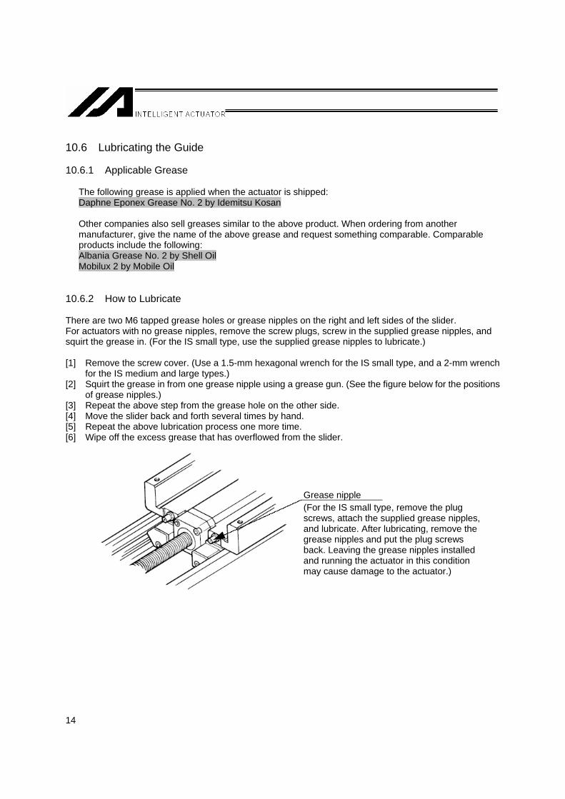
10.6.2 How to Lubricate There are two M6 tapped grease holes or grease nipples on the right and left sides of the slider. For actuators with no grease nipples, remove the screw plugs, screw in the supplied grease nipples, and squirt the grease in. (For the IS small type, use the supplied grease nipples to lubricate.) [1] Remove the screw cover. (Use a 1.5-mm hexagonal wrench for the IS small type, and a 2-mm wrench
for the IS medium and large types.) [2] Squirt the grease in from one grease nipple using a grease gun. (See the figure below for the positions
of grease nipples.) [3] Repeat the above step from the grease hole on the other side. [4] Move the slider back and forth several times by hand. [5] Repeat the above lubrication process one more time. [6] Wipe off the excess grease that has overflowed from the slider.
Grease nipple (For the IS small type, remove the plug screws, attach the supplied grease nipples, and lubricate. After lubricating, remove the grease nipples and put the plug screws back. Leaving the grease nipples installed and running the actuator in this condition may cause damage to the actuator.)

15
10.7 Lubricating the Ball Screw 10.7.1 Ball Screw Grease
The following dedicated grease is applied to the ball screw when the actuator is shipped: Mal Temp LRL No. 3 by Kyodo Yushi
This product is well suited for ball screws and has excellent properties such as low heat generation. For comparable products, see guide grease (lithium grease).
Warning: Never use fluorine-based grease. If fluorine-based grease is mixed with lithium-based grease, the grease not only loses its performance but it can actually damage the actuator.
10.7.2 How to Lubricate Clean the screw, and then apply grease with your finger and spread it out by moving the slider back and forth. Finally, wipe off any excess grease that has overflowed from the nut. The above procedure should be followed because if too much grease is applied, the agitation resistance increases and the ball screw generates heat more easily. Also when the ball screw rotates, excess grease is splattered on the surrounding areas.

16
10.8 Lubricating the Intermediate Support (Intermediate support types M-X-MX, L-X-MX and L-X-UWX) 10.8.1 Applicable Grease
The following dedicated grease is applied to the intermediate support when the actuator is shipped: Mal Temp LRL No. 3 by Kyodo Yushi
Warning: Never use fluorine-based grease. If fluorine-based grease is mixed with lithium-based grease, the grease not only loses its performance but it can actually damage the actuator.
10.8.2 How to Lubricate (1) Connecting rods
Clean the right and left intermediate-support connecting rods, and then apply grease with your finger and spread it out by moving the slider back and forth.
Connecting rods

17
(2) Support bushes
Clean the support bushes for the intermediate supports on both ends, and then apply grease around each support bush with your finger while turning the support bush. After grease has been applied, spread it out by moving the slider back and forth.
(3) Top faces of slider and intermediate support
Clean the top faces of the slider and intermediate supports on both sides, and then apply grease with your finger.
Top faces of slider Intermediate support
Support bushes

18
11. Warranty 11.1 Warranty Period The warranty period expires upon elapse of one of the following periods, whichever is the shortest.
18 months after shipment from IAI 12 months after delivery to the specified location 2,500 hours of operation
11.2 Scope of Warranty If a breakdown occurs within the period specified above due to defective material or poor craftsmanship, we will repair the actuator at no cost. However, the following items are not covered by this warranty: • Faded paint or other changes that occur naturally over time. • Consumable components that wear out with use. • The actuator is noisy or similar impressions that do not affect machinery performance. • Damage resulting from improper handling by the user or lack of proper maintenance. • Alteration not made by IAI or its representatives. • Breakdown caused by using a controller or controllers not manufactured by IAI. • Damage caused by fire or other natural disaster or due to an accident. The warranty pertains to the purchased product itself and does not cover any damage that might arise from a breakdown of the supplied product. All repairs will be done at our factory. Even if the product is still covered by the warranty, we will assess a separate charge for sending technicians to the customer's site.

19
12. How to Use the Homing Mark Stickers
Attach these stickers to the product, as necessary, to indicate the home direction of the actuator, etc. [1] For marking the home direction of the actuator [2] As positioning marks [3] For displacement check • Attach two stickers when the actuator is stopped at home.
Sticker details
x 1 sheet
Homing mark stickers
Graduation mark sticker x 4 (The graduations are provided for 10 mm at a 1-mm pitch.)
Examples of use
Attach to the slider.
Attach to the base.
Attach at desired moving positions.
Attach on the home side of the base.
Motor
Mark sticker x 4
• Remove each sticker from the backing paper when use. Notes 1. The back side is adhesive. 2. Remove dirt and oil from the attaching surface beforehand. 3. Avoid attaching the stickers over the caution labels.
Motor
Attach to the slider.
Attach to the slider.

20
13. Motor Replacement Procedure for ISA/ISPA Series
This manual details the procedure for replacement of an ISA Series motor. When you need to replace your motor, please follow the steps described below. Because the screws and other components removed during replacement of the motor will be needed for reassembly, prepare a storage box in advance to keep those components so that you don’t lose or misplace them.
13.1 Removing the Motor Unit 13.1.1 Removing the Screw Cover Turn off the power supply to the controller, and then disconnect the motor cable and encoder cable. Remove the four thin-head screws used for mounting the screw cover, and take out the cover. If the cover cannot be taken out completely, move the screw cover out of the way so that the procedure described in Section 1.2 can be performed.
The ISA-SXM model is shown above.
Controller
Motor cable
Encoder cable
Connector
Thin-head mounting screw
Screw cover
Thin-head mounting screw

21
13.1.2 Removing the Seat Cover Peel off the seat cover provided on the motor side. You can now see the ball screw side of the coupling. If the actuator is equipped with a brake, connect the encoder cable and apply power to the controller to release the brake. Then move the slider so that the coupling bolts on the ball screw side can be removed. After moving the slider, deactivate the brake release, turn off the power to the controller and disconnect the encoder cable.
Caution: • If the actuator is vertically mounted (Z axis), exercise due caution so that the slider doesn’t fall when the brake is released.
• If you attempt to move the slider with the motor cable connected, the slider movement will become heavy due to regenerative braking. Disconnect the motor cable before moving the slider.
Ball screw
Coupling on the ball screw side
Coupling on the motor side
Motor unit
The coupling is visible.
The seat cover need not be removed if the cover is already separated from the hole, as shown to the left.

22
13.1.3 Removing the Motor Cover Remove the four bolts that secure the motor cover.
<List of Cover Mounting Bolts> Bolt used
Type Motor
output (W) Location Nominal diameter Length Quantity
S 60 Common M3 55 2 Top side 55 2 100 Bottom side 45 2 Top side 70 2 M
200 Bottom side 60 2 Top side 75 2 200 Bottom side 60 2 Top side 100 2 L 400 Bottom side
M4
85 2
13.1.4 Removing Wire/Cable Lines for the Motor Unit (1) Remove the ground line, which is bolted to the motor bracket. (2) Disconnect the encoder signal line connector and the motor power line connector.
* If a brake is provided, the brake lead connector should also be disconnected.
Top side
Bottom side
M3 x 5

23
The photo below shows how the motor looks when the motor cover and all connectors are removed.
Caution: • If the actuator is equipped with a brake, exercise caution not to pull out the brake lead line. If the connector is engaged inside the actuator, forcibly pulling out the brake lead line may cause the connector to come off inside the actuator.
13.1.5 Removing the Motor Unit (1) Move the slider to a position in which the coupling bolts on the ball screw side can be loosened. If a
brake is provided, this procedure should be completed before the seat cover is removed as described in Section 1.2.
(2) Loosen the coupling bolts on the ball screw side.
Encoder signal line Motor power line
Brake lead line

24
(3) Remove the motor mounting bolts, and then pull the motor unit and coupling out of the motor housing.
[Motor housing] [Motor unit]
Motor mounting bolts (four locations)
Coupling

25
13.2 Installing a New Motor Unit 13.2.1 New Motor Unit The new motor unit will be supplied together with the coupling installed as shown below.
Caution: • Under no circumstances should the coupling on the motor side be loosened
13.2.2 Aligning the Slider Position 13.2.2.1 Connecting the Motor Unit Connect the motor cable and encoder cable provided with the motor cover (which has been removed) to the motor unit, and then connect them to the controller using trunk cables (motor cable and encoder cable). 13.2.2.2 Action to Be Taken upon Error If the code display on the front panel of the controller does not show “rdy” or “Ardy” but an alarm generates instead when the controller power is turned on, check the operating manual and take proper actions. If the problem persists, contact IAI. * If the code display shows “Erg,” it means an emergency stop has been actuated. * If the code display shows “ECA1,” an absolute reset must be performed.
The coupling is already installed.
Caution
Code display

26
13.2.2.3 Adjusting the Slider Position Place a spacer (jig or block gauge) having a specified thickness between the mechanical end of the home position and the slider, and then press them firmly against one another so as not to allow for gaps. If the actuator is equipped with a brake, apply power to the controller to release the brake before moving the slider. After moving the slider, deactivate the brake release, turn off the power to the controller and disconnect the brake lead line connector. The thickness of the spacer will differ according to the home offset distance, the SE (stroke end) to ME (mechanical end) distance and the actuator type. (See Attachment 1 on Page 30.) If the actuator is of reversed home specification, see Attachment 2 on Page 31.
Standard Home Specification [When the slider jigs, etc., can be removed]
Spacer See Attachment 1 on Page 30 for the distance of the gap.

27
Standard Home Specification
[When the jigs on the slider cannot be removed]
Adjust this section to the appropriate dimension shown in the table in the attachment. In this case, use of a block gauge, etc., is also recommended. (See Attachment 2 on Page 31 for the distance.)

28
Reversed Home Specification (Single-slider Specification)
[When the slider jigs, can be removed]
* The photograph shows a brake type actuator (optional).
Reversed Home Specification (Single-slider Specification) [When the jigs on the slider, etc., cannot be removed]
Spacer
Motor
See Attachment 1 on Page 30 for the distance of the gap.
X or Z-axis Y-axis
Adjust this section to the appropriate dimension shown in the table in the attachment. In this case, use of a block gauge, etc., is also recommended. (See Attachment 2 on Page 31 for the distance.)

29
Reversed Home Specification (Double-slider Specification)
[When the slider jigs on the slider, etc., can be removed]
* In the case of a double-slider actuator (custom order) of reversed home specification, the driving slider is on the motor end and the slider on the other end becomes a free slider.
* On a double-slider actuator of reversed home specification, the driving slider and free slider must be
affixed. (See the custom order drawings for the span between the two sliders.)
Reversed Home Specification (Double-slider Specification) [When the jigs on the slider, etc., cannot be removed]
* In the case of a double-slider actuator (custom order) of reversed home specification, the driving slider is on the motor end and the slider on the other end becomes a free slider.
* On a double-slider actuator of reversed home specification, the driving slider and free slider must be
affixed. (See the custom order drawings for the span between the two sliders.)
Spacer Span
This slider is directly connected to the ball screw. Affixed.
Motor Free slider Driving slider
See Attachment 1 on Page 30 for the distance of the gap.
Adjust this section to the appropriate dimension shown in the table. In this case, use of a block gauge, etc., is also recommended. (See Attachment 2 on Page 31 for the distance.)
Span This slider is directly connected to the ball screw.
Motor Free slider Driving slider

30
(Attachment 1) Spacer Thickness by Model
~ Thickness of Spacer Used When Installing the Motor ~
The thickness of the spacer differs according to the actuator type and ball screw lead. Prepare a spacer by referring to the charts below. To determine the actuator type and ball screw lead length, check the model code indicated on the label affixed to the actuator.
[How to Read the Model Code and Select a Spacer]
Series Type Encoder type Motor output Lead Stroke Applicable controller Cable length Option
ISA LYM A 200 20 600 T1 M AQ-NM
Since the above code includes the “L ” type and 20 mm lead, the spacer 4.0 mm in thickness should be used.
<Standard>
Type Lead (mm) Spacer thickness (mm) 4 2.0
S 8 • 16 3.0
5 2.0 M
Other than 5 4.0 L All 4.0
<Equipped with a limit switch = Equipped with a home position sensor>
Type Lead (mm) Spacer thickness (mm) S All 3.5 M All 4.0 L All 4.0
* The above charts also apply to the models in which the home position is set on the opposite side of the motor.

31
(Attachment 2) Dimension Table by Model
Standard home specification <Not equipped with a limit switch = Not equipped with a home position sensor>
Type Lead Adjust dimension to: (mm)
4 36 S M 8 • 16 37
5 49 M M 10 • 20 • 30 51 MXMX 10 • 20 • 30 99 L M 10 • 20 • 30 • 40 54 LXMX
LXUWX 20 • 30 • 40 106
<Equipped with a limit switch = Equipped with a home position sensor>
Type Lead Adjust dimension to: (mm)
S M All 37.5 M M All 51 MXMX All 99 L M All 54 LXMX
LXUWX All 106
Reversed home specification <Not equipped with a limit switch = Not equipped with a home position sensor>
Type Lead Adjust dimension to: (mm)
4 21 S M 8 • 16 22
5 29 M M 10 • 20 • 30 31 MXMX 10 • 20 • 30 79 L M 10 • 20 • 30 • 40 32 LXMX
LXUWX 20 • 30 • 40 78
<Equipped with a limit switch = Equipped with a home position sensor>
Type Lead Adjust dimension to: (mm)
S M All 22.5 M M All 31 MXMX All 79 L M All 32 LXMX All
LXUWX All 78

32
13.2.3 Aligning the Motor Position Apply power to the controller, and then run the motor with the jog control using the PC software or teaching pendant to align the home position marked on the motor and the slit in the coupling. (Jog at 1 mm per second (minimum speed)). * In certain situations such as when the controller is away from the motor, you can turn on the servo after
aligning the coupling and slit positions by hand. 13.2.4 Installing the Motor Unit Temporarily (1) With the motor servo turned on, fit the motor unit’s coupling in the end of the ball screw shaft and
fasten the motor housing and motor unit temporarily. (Tighten manually for this temporary purpose.)
Type Motor output (W) Bolt used Quantity
S 60 M4 x 10 2 100 M 200 200 L 400
M5 x 12 4
Caution: • Install the motor unit so that the motor power line is located on the right side. • When fastening the motor and motor housing temporarily, be sure to place them next
to each other with no gaps or play.
Motor mounting bolts (Four locations)
Power line
33
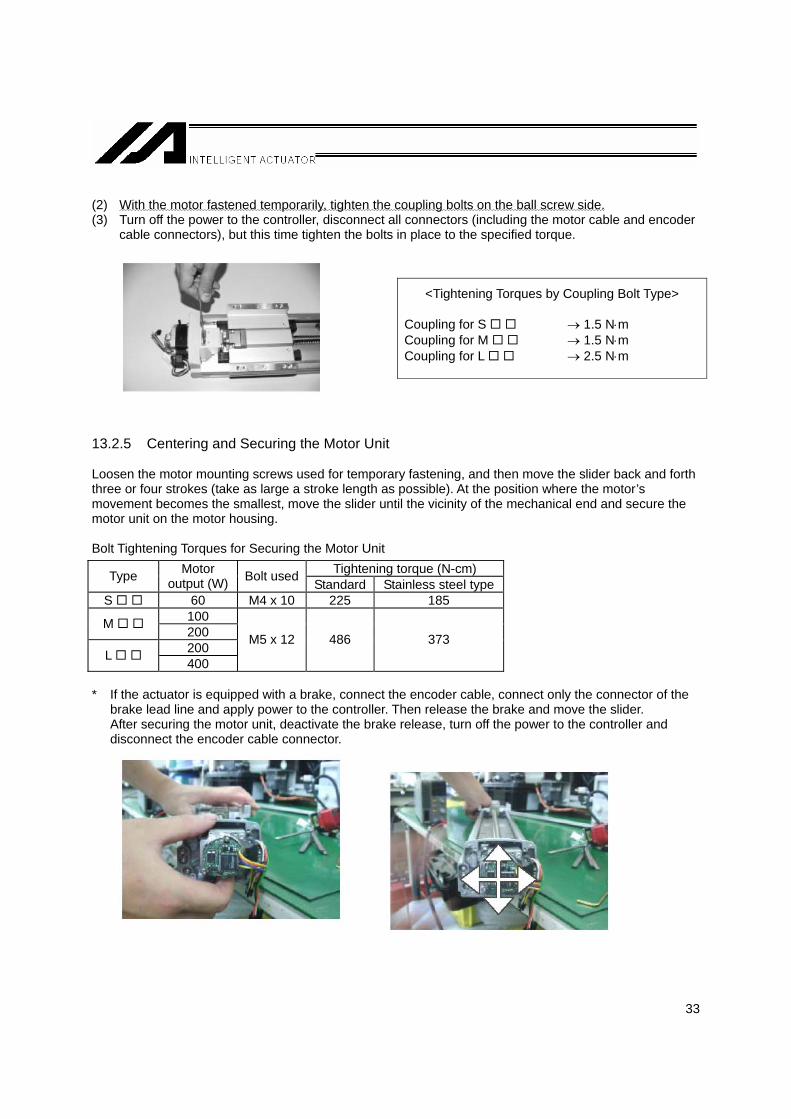
(2) With the motor fastened temporarily, tighten the coupling bolts on the ball screw side. (3) Turn off the power to the controller, disconnect all connectors (including the motor cable and encoder
cable connectors), but this time tighten the bolts in place to the specified torque. 13.2.5 Centering and Securing the Motor Unit Loosen the motor mounting screws used for temporary fastening, and then move the slider back and forth three or four strokes (take as large a stroke length as possible). At the position where the motor’s movement becomes the smallest, move the slider until the vicinity of the mechanical end and secure the motor unit on the motor housing. Bolt Tightening Torques for Securing the Motor Unit
Tightening torque (N-cm) Type Motor output (W) Bolt used Standard Stainless steel type
S 60 M4 x 10 225 185 100 M 200 200 L 400
M5 x 12 486 373
* If the actuator is equipped with a brake, connect the encoder cable, connect only the connector of the
brake lead line and apply power to the controller. Then release the brake and move the slider. After securing the motor unit, deactivate the brake release, turn off the power to the controller and disconnect the encoder cable connector.
<Tightening Torques by Coupling Bolt Type> Coupling for S → 1.5 N⋅m Coupling for M → 1.5 N⋅m Coupling for L → 2.5 N⋅m
34
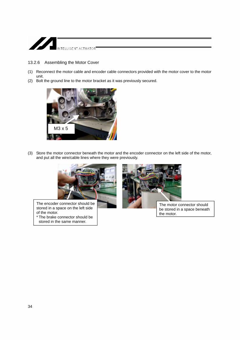
13.2.6 Assembling the Motor Cover (1) Reconnect the motor cable and encoder cable connectors provided with the motor cover to the motor
unit. (2) Bolt the ground line to the motor bracket as it was previously secured. (3) Store the motor connector beneath the motor and the encoder connector on the left side of the motor,
and put all the wire/cable lines where they were previously.
M3 x 5
The encoder connector should be stored in a space on the left side of the motor. * The brake connector should be
stored in the same manner.
The motor connector should be stored in a space beneath the motor.
M3 x 5

35
(4) Secure the motor cover in place.
Caution 1: • Be careful not to pinch wires between the main body and the cover. Caution 2: • The motor cover is made of plastic. When securing the cover, be careful not to
damage the cover by tightening the bolts too much.
13.2.7 Installing the Screw Cover (1) Install the seat cover. (2) Install the screw cover in the manner it was previously installed.
Thin head screw x 2 Screw cover
If the original condition was pattern [1], change it to pattern [2].
[1] [2]
Install the seat cover so that the coupling check window becomes visible.
Thin head screw x 2
36
13.3 Correcting for Position Deviation (1) Connect the motor cable and encoder cable and turn on the controller power. (2) Use the PC software or teaching pendant to perform homing and check the home position. Repeat
homing several times to confirm that the actuator returns to the same position. (If the actuator is of absolute specification, perform an absolute reset.)
(3) Check the amount of position deviation.
The position may have changed slightly from where it was before the motor was replaced. Accordingly, select a desired position number that allows you to check the amount of deviation before and after the replacement, and then perform positioning to that position and measure the amount of deviation.
(4) Reflect the amount of deviation in the home offset parameter.
[For the setting method, see Attachment 1, 2 or 3.] * If the two positions differ significantly (one ball screw revolution or more = lead or more) or if the
actuator does not return to the same position when homing is repeated, install the motor unit again by following the procedure described in this manual. When the motor unit was installed, a wrong spacer size may have been used or the slider may have moved instead of remaining stationary at the mechanical end.

37
Attachment 1: How to Set Home Preset Value (with XSEL or SSEL Controller) (1) Open the position edit screen.
On the PC software screen, click , select a desired position number, and then click OK to display the following screen.
(2) Compare the current value and the value achieved by positioning the actuator to the selected position
number, and check the amount of deviation. (3) Open the parameter screen.
The current value is displayed.
Position number
[2] Click MV.
[1] Select the position to move the actuator to.
Click this button to open the parameter edit screen.
Click this button to open the position edit screen.

38
(4) Select the axis-specific parameter tab. (5) In the axis-specific parameter tab, select No. 12, “Home preset value.” (6) Change the setting of axis-specific parameter No. 12 (home preset value).
Add or subtract the value measured in (2) to/from the value currently input. The setting unit is 0.001 mm. Example: When subtracting 1 mm Current preset value = Current setting – 1000
(7) Write the new data.
Select Axis-specific.
Select No. 12, “Home preset value.”
Click the SEL button to write the data to the controller.

39
(8) Transfer the data to the controller. (9) Click OK. (10) Write the data to the flash ROM. (11) Restart the controller.
Select the Parameters check box.
Select Yes.

40
Attachment 2: How to Set Home offset (with ECON or SCON Controller) (1) Open the position edit screen.
On the PC software screen, click , select a desired position number, and then click OK to display the following screen.
(2) Compare the current value and the value achieved by positioning the actuator to the selected position
number. (3) Open the parameter screen.
Click this button to open the position edit screen.
Point number
[2] Click this button to make a step movement.
[1] Select the position.
Click this button to open the parameter screen.
The current value is displayed.

41
(4) The user parameter screen appears. (5) Change user parameter No. 22 (home offset).
* The setting unit is mm. Add or subtract the value measured in (2) to/from the value currently input. Example: When subtracting 0.5 mm Home offset = Current setting – 0.5 mm
(6) Write the new data.
Click the controller transfer button, and then click OK. * After the data has been written, turn off the controller power.
Click the controller transfer button.
Click OK.

42

43
Attachment 3: How to Set Home offset (with P-Driver Controller) (1) Open the jog screen.
Click the jog button on the PC software screen. Next, select the pulse mode.
(2) Position the actuator to a desired position and compare the command pulse position and the position
actually achieved, and write down the difference. Adjust the position by jogging the actuator or by turning off the servo and moving the actuator manually.
Compare against this position. Servo ON/OFF button
Jog button

44
(3) Open the parameter edit screen. (4) Change the setting of No. 13, “Home offset.”
* The setting unit is pulse. Add or subtract the value measured in (2) to/from the value currently input. Example: When subtracting 150 pulses Home offset = Current setting – 150
(5) Write the new data.
Click the driver transfer button, click OK, and then click Yes. (The controller will restart.)
Click this button to open the parameter screen.
Driver transfer button

45

46

47


Catalog No.: MJ3606-15A
Head Office: 2690 W. 237th Street, Torrance, CA 90505 TEL (310) 891-6015 FAX (310) 891-0815
Chicago Office: 1261 Hamilton Parkway, Itasca, IL 60143 TEL (630) 467-9900 FAX (630) 467-9912
Atlanta Office: 1220-E Kenneston Circle, Marrietta, GA 30066 TEL (678) 354-9470 FAX (678) 354-9471
website: www.intelligentactuator.com
Ober der Röth 4, D-65824 Schwalbach am Taunus, Germany TEL 06196-88950 FAX 06196-889524
The information contained in this document is subject to change without notice for the purpose of product improvement. Copyright © 2007. JUL. IAI Corporation. All rights reserved.