
Acoustic_Fatigue_White.pdf
22
Composite Structures 16 (1990) 171-192 Developments in the Acoustic Fatigue Design Process for Composite Aircraft Structures R. G. White Institute of Sound and Vibration Research, University of Southampton,Southampton, Hants SO9 5NH, UK ABSTRACT A current approach to the acoustic fatigue analysis of composite structures is reviewed which is based upon the single mode method used previously for metallic aircraft structures. Some recent developments in acoustic fatigue studies are outlined and progressive wave tube testing at elevated temperatures is described. A recently developed method for fatigue testing composite material specimens in flexure is presented together with fatigue data for a composite material in several environ- mental conditions. The occurrence of residual thermal stresses in composite materials has been studied and future work required concern- ing three dimensional stress prediction methods and design procedures is discussed. 1 INTRODUCTION The use of composite materials in aircraft structures has increased considerably in recent years and some trends in the use of carbon com- posites are given in Fig. 1 from Ref. 1. Whilst projection of material usage over several decades is difficult in any industry, it is extremely difficult to make this type of prediction in the aircraft industry because such data are very much dependent upon the initiation and continuance of several major projects at national and international level. However, the industry- based data given by Lowson 1 clearly show that the use of composite materials for aircraft structures, both in the military and civil sectors, is increasing and is likely to continue to increase in the future. There is obviously a need to design composite aircraft structures and components to adequately resist dynamic loading and part of this is the high 171 Composite Structures 0263-8223/90/S03.50 © 1990 Elsevier Science Publishers Ltd, England. Printed in Great Britain
description
Acoustic Fatigue in Composite structures
Transcript of Acoustic_Fatigue_White.pdf

Composite Structures 16 (1990) 171-192
Developments in the Acoustic Fatigue Design Process for Composite Aircraft Structures
R. G. Whi te
Institute of Sound and Vibration Research, University of Southampton, Southampton, Hants SO9 5NH, UK
A B S T R A C T
A current approach to the acoustic fatigue analysis of composite structures is reviewed which is based upon the single mode method used previously for metallic aircraft structures. Some recent developments in acoustic fatigue studies are outlined and progressive wave tube testing at elevated temperatures is described. A recently developed method for fatigue testing composite material specimens in flexure is presented together with fatigue data for a composite material in several environ- mental conditions. The occurrence of residual thermal stresses in composite materials has been studied and future work required concern- ing three dimensional stress prediction methods and design procedures is discussed.
1 INTRODUCTION
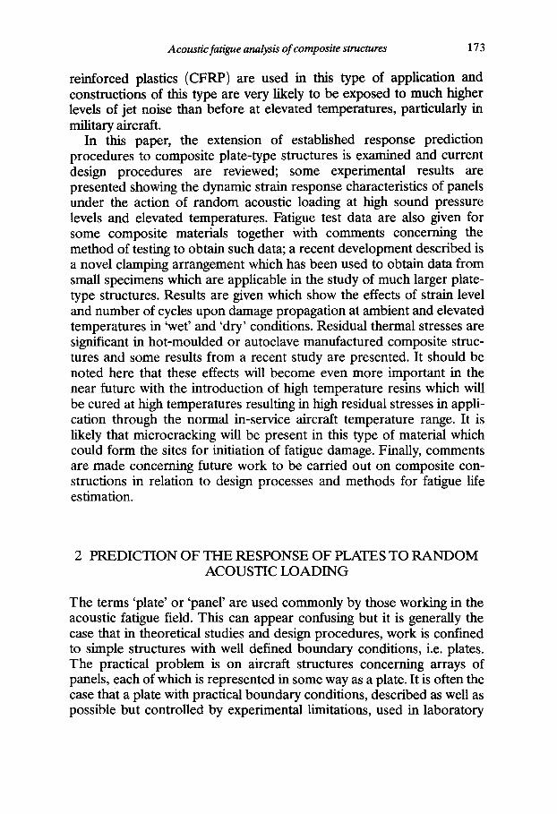
The use of composite materials in aircraft structures has increased considerably in recent years and some trends in the use of carbon com- posites are given in Fig. 1 from Ref. 1. Whilst projection of material usage over several decades is difficult in any industry, it is extremely difficult to make this type of prediction in the aircraft industry because such data are very much dependent upon the initiation and continuance of several major projects at national and international level. However, the industry- based data given by Lowson 1 clearly show that the use of composite materials for aircraft structures, both in the military and civil sectors, is increasing and is likely to continue to increase in the future. There is obviously a need to design composite aircraft structures and components to adequately resist dynamic loading and part of this is the high
171 Composite Structures 0263-8223/90/S03.50 © 1990 Elsevier Science Publishers Ltd, England. Printed in Great Britain

172 R. G. White
% Weight
60
50
40
30
20
10
Fig. 1.
Military Aircraft
Helicopters
Civil Aircraft
I I 1970 1980 1990 2000 2010
Trends in carbon composite materials use in aircraft)
frequency loading due to pressure excitation such as jet noise, turbulence, etc. There has been, in particular, considerable interest in the response of thin, stiffened-skin structures to jet noise, that is random acoustic loading. Originally, the problem confronting the designer was to design aluminium alloy structures composed of thin skin attached, by riveting, bonding, or a combination of techniques, to ribs and stringers so that the built-up structure had adequate fatigue life. In order that dynamic response predictions can be made at the design stage it is obviously desirable that relatively simple design procedures be deve- loped. A considerable amount of work has been carried out in the past on arrays of panels in what were then typical fuselage, empennage and control surface constructions, although the design problem was simplified in two ways to yield reasonable dynamic response estimates for these types of structure under the action of broadband random acoustic loading. The two simplifications were first, to consider a panel in an array to be a plate with boundary conditions which could be reasonably approximated by classical plate theory, and second, to reduce the multi-modal response problem to that of fundamental mode response prediction only. These approximations generally form the basis of acoustic fatigue assessment procedures used by the UK aircraft industry over about the past three decades. The methods are well established and proven. However, with developments in aircraft con- struction, configurations and propulsion systems, reappraisal of design procedures has been necessitated in recent years. In particular, as already noted above, composite constructions have been introduced, commonly in the form of fibre reinforced resins either used in skin material or as face plates for honeycomb construction. Carbon fibre
Acoustic fatigue analysis of composite structures 173
reinforced plastics (CFRP) are used in this type of application and constructions of this type are very likely to be exposed to much higher levels of jet noise than before at elevated temperatures, particularly in military aircraft.
In this paper, the extension of established response prediction procedures to composite plate-type structures is examined and current design procedures are reviewed; some experimental results are presented showing the dynamic strain response characteristics of panels under the action of random acoustic loading at high sound pressure levels and elevated temperatures. Fatigue test data are also given for some composite materials together with comments concerning the method of testing to obtain such data; a recent development described is a novel clamping arrangement which has been used to obtain data from small specimens which are applicable in the study of much larger plate- type structures. Results are given which show the effects of strain level and number of cycles upon damage propagation at ambient and elevated temperatures in 'wet' and 'dry' conditions. Residual thermal stresses are significant in hot-moulded or autoclave manufactured composite struc- tures and some results from a recent study are presented. It should be noted here that these effects will become even more important in the near future with the introduction of high temperature resins which will be cured at high temperatures resulting in high residual stresses in appli- cation through the normal in-service aircraft temperature range. It is likely that microcracking will be present in this type of material which could form the sites for initiation of fatigue damage. Finally, comments are made concerning future work to be carried out on composite con- structions in relation to design processes and methods for fatigue life estimation.
2 PREDICTION OF THE RESPONSE OF PLATES TO RANDOM ACOUSTIC LOADING
The terms 'plate' or 'panel' are used commonly by those working in the acoustic fatigue field. This can appear confusing but it is generally the case that in theoretical studies and design procedures, work is confined to simple structures with well defined boundary conditions, i.e. plates. The practical problem is on aircraft structures concerning arrays of panels, each of which is represented in some way as a plate. It is often the case that a plate with practical boundary conditions, described as well as possible but controlled by experimental limitations, used in laboratory
174 R. G. White
studies in acoustic fatigue tests is also referred to as a panel. Both terms are used in this section of the paper which begins with some simple theoretical considerations which form the basis of current design methods. This is followed by an outline of the data sheet approach to design with reference to design guides produced by ESDU International.
2.1 The basis of the method
The forced vibration of a plate by a sound field has been examined by many workers but a good statement of the problem is given by Clarkson 2, 3 who simplified the multi-modal response prediction problem and developed the method which has been used for dynamic response prediction of metallic, panel-type structures. Attention is drawn to this paper because the approximations inherent in the single mode response prediction method are stated there, the method is validated for aircraft structures and extension of the procedure to composite panels is still based upon Clarkson's work. Assuming that the response of a panel-type structure can be represented by a plate which is vibrating predominantly in its fundamental mode, then the mean square bending stress at the point of interest is given by:
3r o (t)= ~ - f, Gp(f,) 02 (1)
where o 0 is the stress at the point of interest due to a uniform unit static pressure of unit magnitude; ~ is the equivalent viscous damping ratio associated with the fundamental resonance; fl is the resonance frequency of the fundamental mode (Hz); Gr(fl ) is the excitation pressure spectral density at frequency f~.
This simple formula has been used as the basis of design methods for estimating the RMS stress in metallic, stiffened skin panels subjected to random acoustic loading? The value ascribed to the equivalent viscous damping ratio, ~, is obviously very important and for metallic structures without special damping treatments a value of ~ = 0.017 has been successfully assumed to be typical. It should be noted here that for light damping it may be assumed that ~ = r//2 where r/is the structural loss factor.
2.2 A current procedure for predicting the acoustically-induced response of composite plates using a 'data sheet' method
With the introduction of composite structures and the use, in particular, of multi-layered CFRP constructions, the initial problem was to consider
Acoustic fatigue analysis of composite structures 17 5
whether or not the well-established method outlined above could be reasonably applied to this type of structure. The secondary problem was that if the method could be applied, how could the required parameters be estimated. The latter point arises because of the wide range of con- stituent materials which could be used in a variety of 'lay-ups', that is relative angles between the fibres in each layer and the plate axis. In pre- vious design procedures for metallic structures, presentation of data in the form of nomographs was possible but because of the above problems with composites it was recognised at an early stage that this degree of simplicity would not be possible and a major part of the simple 'engi- neering' approach to design is based upon use of computer programs for dynamic response prediction. It must also be noted at this stage that most theoretical and experimental work on composite plates involves strain prediction/measurement rather than stress, and fatigue work is usually based upon surface strain criteria. Therefore, predictions based upon eqn (1) are presented as RMS strains. It must be said here that cur- rent design procedures have obviously, as outlined above, evolved from approaches used for the study of metallic structures. The usefulness of surface strain as a possible fatigue indicator for a composite structure can obviously be debated as it is the combination of internal stresses/ strains at some critical point or within some small critical volume inside the structure which will cause fatigue damage to initiate and propagate. Three dimensional stress/strain prediction within composite structures is, of course, possible and, as described later, work is underway to esta- blish the critical internal loading states which create fatigue damage. At the time of writing, dynamic surface strains are, however, used as a refer- ence level to judge whether or not, for a given 'lay-up', there is likely to be a fatigue problem. The overall process is therefore to estimate the RMS surface strain of the structure (represented as a plate) to the pre- scribed loading and then to estimate fatigue life from knowledge of the predominant frequency of oscillation and fatigue data for the material, analogous to the S / N (stress versus number of cycles to failure) data used in the past for metallic structures. A method for presenting fatigue data for composites is described later in the paper.
Aircraft and component manufacturers worldwide tend to have acoustic fatigue designers who use a variety of methods for structural design. In the UK, a lead has been taken by ESDU International, a com- mercial organisation which originated in the Royal Aeronautical Society, in producing data sheets. A range of these are listed in the Appendix (Refs A.1-A.9 are listed separately from research publications in the main reference list) to illustrate an acoustic fatigue design approach which originated in the UK aircraft industry but which encompasses
176 R. G. White
theoretical models and experimental data bases gathered from literature surveys in the general open literature and which is available inter- nationally. It is not the purpose of this paper to advocate the use of any particular method but to draw to the reader's attention some recent developments in the field.
Before applying any theory, simple or otherwise, or proceeding to use strain prediction methods, it is sensible to study design procedures which are based upon previously established good practice. For design of aircraft structures against acoustic fatigue, consideration should be given to structural configurations which are most suited for use in high noise level environments. The attention of the reader is drawn to reference A.1 in which guidance is given on good design practices, including information on composite structures. Having established a basic structural configuration, the choice of materials and 'lay-up' then has to be made. An advantage of fibre reinforced composites is that their strength and stiffness properties may be arranged to resist the loads to be carried, this is the so-called 'tailoring' process. The structure may be tailored to meet requirements by the use of multi-layered laminates with appropriate relative orientations of the principal fibre directions within the layers of composite material, the laminae. The material properties of laminated plates may be estimated using Ref. A.2. This item provides stiffness sub-matrices in the plate constitutive equations or, alternatively, the apparent elastic properties for use when the laminate is assumed to act as an orthotropic plate. These material properties may be estimated either from the individual layer properties or from the fibre and matrix properties in each layer and their volume fractions. It is clear from eqn (1) that the estimation of strain response under the action of broadband random acoustic loading of a panel requires knowledge of the funda- mental natural frequency and associated modal damping ratio. First, consider natural frequency estimation. Natural frequencies of flat and curved laminated plates may be estimated using Refs A.3 and A.4 respectively. Similar data may be derived for sandwich panels with laminated face plates using Ref. A.5. Experimental natural frequency data are required to validate the theoretical prediction methods for curved plates and sandwich panels and this is an area in which further work should be done. A method for predicting material damping in fibre reinforced composite laminated plates is provided in A.6 for rectangular plates having all edges simply supported or all edges clamped, the procedure having been validated for plates with free edges; it is likely, however, that experimentally determined values of ~ will often be used in RMS strain predictions and there is a great need to form a 'bank' of
Acoustic fatigue analysis of composite structures 177
measured data for various types of structure. It must be realised that damping arises from a variety of sources in a built-up structure, such as material damping which is low for metals, damping at joints, friction, aerodynamic damping and acoustic radiation. In the case of composite structures, the situation is more complicated. The same mechanisms prevail but material damping will, in addition, depend upon matrix properties and 'lay-up' to some extent. It has been proposed in A.7 that a typical equivalent viscous damping ratio for an individual plate within an array in a CFRP structure is 0.025 but it is advised that if this reference value is used, the estimated RMS strain may be factored by the square root of the ratio of damping values for other situations. Internal damping in a composite depends upon a range of parameters such as the effects of temperature on matrix energy dissipation, damage, etc. It is the author's experience that composites have essentially linear damping and hence the material loss factor does not significantly depend upon strain amplitude.
With a knowledge of the acoustic pressure loading on a plate, the fundamental natural frequency and associated damping, the induced RMS surface strain may be estimated using the simple, single mode theory outlined above. Methods for predicting the RMS surface strains on fibre reinforced laminated plates and on the laminated face plates of sandwich panels subjected to random acoustic loading are given in Refs A.7 and A.8 respectively. Again, this is an area in which experimental work is very much required to measure, in progressive wave tube experi- ments, dynamic strains on both faces of flat and curved panels with boundaries and edge closure arrangements such as are used in aircraft structures. The prediction scheme for singly-curved sandwich panels suggests that strains at the centre of a panel are higher on the convex face than on the concave surface. For discussion of edge effects in honeycomb panels, attention is drawn to Ref. 5. The final objective of an investiga- tion of the response of a structure to acoustic loading is to estimate the life under in-service conditions. Life is investigated from some type of endurance plot of damage propagation data, as already outlined above, as a function of stress or strain level and number of loading cycles. An experimental technique is discussed later and some recently obtained data are presented. For composite structures, endurance data are specific to the type of material specimen tested, the method of test and the method of damage detection. For composite structural elements, unless specific data are available (i.e. identical lay-up, etc.) and mode of structural response, published endurance data may only be used as a guide for life estimation. Some endurance data for laminated structural
178 R. G. White
elements are provided in Ref. A.9 but there is a great need for much more data on typical structural elements to extend the endurance data base.
2.3 Consideration of nonlinearity
It is clear from above that the RMS strain prediction method now in use for rectangular composite plates is based upon eqn (1) which depends upon linear behaviour. It has already been established 6 that for very thin plates at high sound pressure levels the response to acoustic loading is nonlinear and simple methods for response prediction are not applic- able. For 'conventional' composite plates the linear prediction method can be applied reasonably to plates with six or more layers; this is essentially the 'thickness requirement' for linear behaviour. However, nonlinear plate vibration is well known to occur at large deflections relative to the thickness. In addition, for plates with static, in-plane compressive loading, in the immediate pre-buckling and the whole of the post-buckling regimes, the vibration is wholly nonlinear in nature with modal coupling, etc., and simple strain response prediction methods cannot be used. 7 It is possible to use simple methods for estimating the lower resonance frequency of the plate but this should not be interpreted as an indicator that response prediction can be simplified in nonlinear regimes.
Work on plates in the post-buckle regime must include consideration of snap-through effects which contribute greatly to the nonlinear behaviour. This has been examined by Ng. 8 It is clear that an 'engineer's' theory or simple method for dynamic strain prediction is required for the post-buckle regime as it is possible for local structure, such as upper wing skin panels in aircraft, to temporarily buckle and recover during flight manoeuvres. Buffet loading could occur in the post-buckle regime and induce high dynamic strains. This problem has been addressed both theoretically and experimentally in Ref. 8 and some simple rules derived for response prediction, based upon observations concerning nonlinear and snap-through type of behaviour. Snap-through behaviour is not currently considered in acoustic fatigue design practice but this type of behaviour can be induced in acoustic excitation of flat and curved plates with static, compressive in-plane loading. Snap-through motion induces a response spectrum which is dominated by frequency content which is in a range below the fundamental natural frequency of a panel-type structure. It is clearly, therefore, a way forward to assess dynamic response of this nature in relation to the static strain. It has been con- cluded by Ng that the RMS response of a plate is comparable to the
Acoustic fatigue analysis of composite structures 179
initial static value when the snap-through motion is continuous. It is also worthy of note that it was also concluded that snap-through effects can be much larger in curved panels than in fiat panels, a surprising result. The post-buckle regime is one in which very high performance is expected of a composite structure and the high endurance characteristics of composites are exploited. In cases where combined loading effects are not dominant and panels are driven by very high sound pressure levels, which have been predicted for future generations of supersonic vehicles (> 170 dB), then nonlinear behaviour of panels will occur and appro- priate response prediction methods will be required. In this regime, snap-through behaviour is not necessarily induced unless there are associated thermal effects which can cause buckling. Nonlinear effects need to be taken into account in the design process, however, because of response harmonic distortion, which is also spatially dependent across the structure, in addition to nonlinear deflection-strain characteristics. 9
3 PROGRESSIVE WAVE TUBE TESTING AT ELEVATED TEMPERATURES
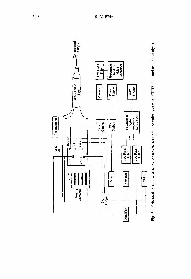
The response of plates to random acoustic excitation may be studied using a progressive wave tube (PWT). For an example of the use of a PWT test of a specimen which leads to the development of an improved structure incorporating additive damping to reduce stresses and improve endurance, see Ref. 10 which also includes results from flight testing. There will always be controversy concerning the response induced during PWT testing compared with that obtained when a structure is mounted close to a jet efflux. The equivalence may be debated because, for example, the damping of a panel will generally appear to be higher when mounted in PWT, due to acoustic interaction with the tunnel, compared with the values found in the normal operating environment. Howver, PWTs are used for experimental work and usually take the basic form similar to that shown in Fig. 2. The ISVR facility includes a heater system for conducting experiments on plates at elevated tempera- tures. Essentially, the apparatus consists of an electropneumatic driver (siren) connected via a horn to a hard-walled parallel duct with an absorbing termination. An aperture in the wall of the duct is used for mounting plate specimens in a supporting flame; the plate can then be exposed to acoustic excitation at grazing incidence in the frequency range of approximately 40-800 Hz. A Wylie Laboratories WAS 3000 siren of 30 000 W has been installed enabling a maximum SPL of 163 dB to be achieved. Signals from the strain measuring system are input to
180 R. G. White
E. ' - 8< 1
o
J \
UJ
4
E~H~
I:
i i i i i
ro x
e....i
© ¢.d,
,=
E
1 ~ 7
eo . .a
¢..;
Acoustic fatigue analysis of composite structures 181
a digital signal processing system to enable the strain spectral density, probability characteristics and modal contribution values to be calcu- lated. The first two types of analyses are conventional but the latter is worthy of explanation. The modal contribution is estimated by dividing the running integral across the strain spectral density curve by the overall mean square strain. A large increase in the parameter at a given frequency is indicative of a large modal contribution at that frequency in the strain spectral density. Use of this parameter is very convenient for determining the quantitative contribution of individual resonances (modes) to the overall response. 6 The apparatus has been used in the past for experiments on plates with in-plane compression (see, for example, Refs 11 and 12) but latterly has been employed in testing at elevated temperatures, as described above, for reasons outlined in the introduction.
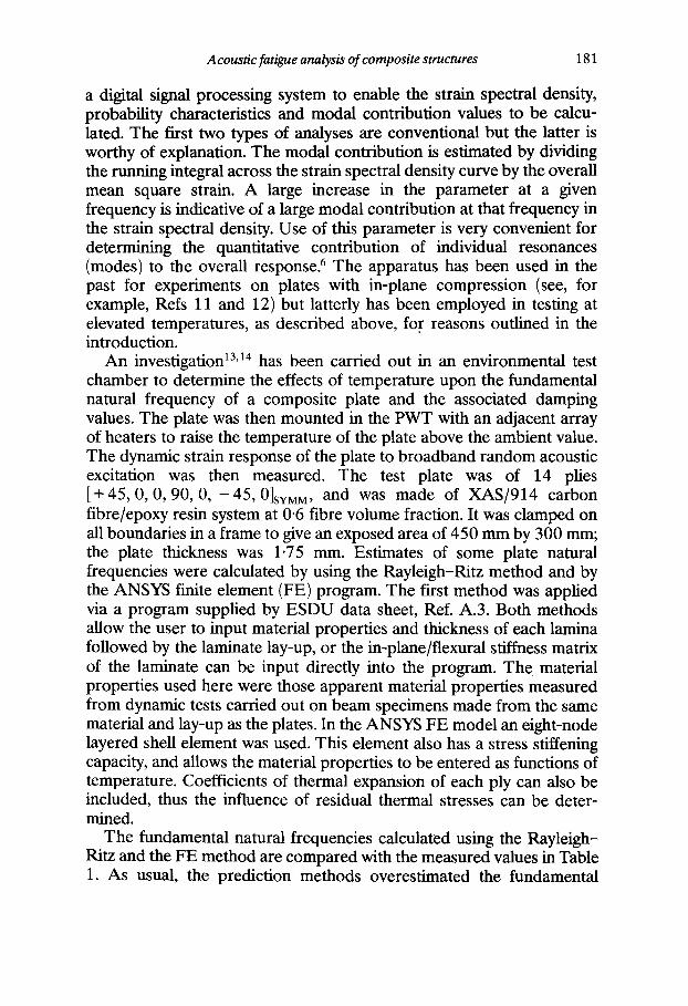
An investigation 13,~4 has been carried out in an environmental test chamber to determine the effects of temperature upon the fundamental natural frequency of a composite plate and the associated damping values. The plate was then mounted in the PWT with an adjacent array of heaters to raise the temperature of the plate above the ambient value. The dynamic strain response of the plate to broadband random acoustic excitation was then measured. The test plate was of 14 plies [+45, 0, 0, 90, 0, - 4 5 , 0]SYMM, and was made of XAS/914 carbon fibre/epoxy resin system at 0-6 fibre volume fraction. It was clamped on all boundaries in a frame to give an exposed area of 450 mm by 300 mm; the plate thickness was 1.75 mm. Estimates of some plate natural frequencies were calculated by using the Rayleigh-Ritz method and by the ANSYS finite element (FE) program. The first method was applied via a program supplied by ESDU data sheet, Ref. A.3. Both methods allow the user to input material properties and thickness of each lamina followed by the laminate lay-up, or the in-plane/flexural stiffness matrix of the laminate can be input directly into the program. The material properties used here were those apparent material properties measured from dynamic tests carried out on beam specimens made from the same material and lay-up as the plates. In the ANSYS FE model an eight-node layered shell element was used. This element also has a stress stiffening capacity, and allows the material properties to be entered as functions of temperature. Coefficients of thermal expansion of each ply can also be included, thus the influence of residual thermal stresses can be deter- mined.
The fundamental natural frequencies calculated using the Rayleigh- Ritz and the FE method are compared with the measured values in Table 1. As usual, the prediction methods overestimated the fundamental
182 R. G. White
TABLE 1 Comparison of Estimated and Measured Values of Funda- mental Natural Frequency of a CFRP Plate Clamped on all Boundaries ([45, 0, 0, 90, 0, -45]SyMM, XAS/914, V F = 0"6,
450 mm x 300 mm x 1"75 mm Estimated at 20°C)
ESDU A N S Y S Measured
103 Hz 100 Hz 96 Hz
TABLE 2 Effects of Temperature on Measured Fundamental Natural
Frequency and Equivalent Viscous Damping Ratio
20°C 80°C 120°C
fl Hz 96 85 80 ~j 0"0085 0"0035 0"007 ~l a 0"020
a ~, = value measured with plate in position in PWT.
natural frequency: also, lack of rigidity of the clamping flame would cause the measured values to be low. The measured fundamental natural frequency reduced by 16% as the temperature increased to 120°C. This was surprising since predictions of fundamental natural frequency due to reduction in material properties, caused by elevated temperatures, predicted a reduction of only 2%. Hence, it would appear that other parameters influence the above phenomenon. Table 2 shows changes of damping with temperature. Elevated temperature tests carried out on the 914 resin showed the damping to be a minimum at approximately 80°C, which could be an explanation for the low value of ~1 at 80°C.
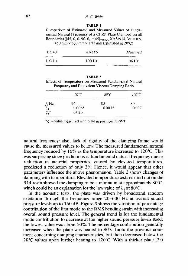
In the acoustic tests, the plate was driven by broadband random excitation through the frequency range 20-600 Hz at overall sound pressure levels up to 160 dB. Figure 3 shows the variation of percentage contribution of the first mode to the RMS bending strain with increasing overall sound pressure level. The general trend is for the fundamental mode contribution to decrease at the higher sound pressure levels used; the lowest value was about 50%. The percentage contribution generally increased when the plate was heated to 80°C (note the previous com- ment concerning damping characteristics) but then decreased below the 20°C values upon further heating to 120°C. With a thicker plate (2.0

Acoustic fatigue analysis of composite structures 183
u~
o
0
f. .
t -
c
U ~
==
100
80
60
u,O
X ~ X
0 20°C
X 80°C
20 "3L" 120°C
0 I i I l I I i
130 Overall Sound Pressure Level
I i
170 (dB)
Fig. 3. Variation of percentage contribution of the fundamental mode to the RMS bending strain at the plate edge with overall sound pressure level and temperature.
mm) of 16 plies, 14 the variation of first mode contribution with temperature and overall sound pressure level was much less pronounced and the value did not fall below 90% for the range of parameters given in Fig. 3. The effects thus appear to be greater for thin plates and the simple response prediction method would appear to be applicable to a reasonably high degree of accuracy for thick plates.
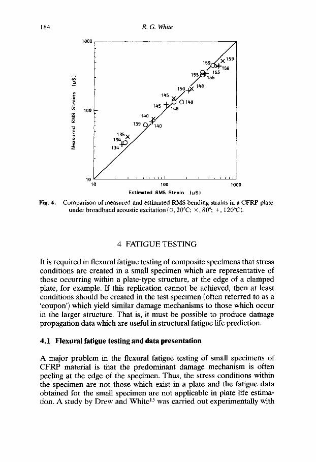
A comparison between predicted RMS strains at a point on the surface of a plate with all boundaries clamped, using Ref. A.7 (remember that this is based upon the single mode model of eqn (1)), is given in Fig. 4 for the 1.75 mm thick plate described above. The numbers ascribed to the plotted points indicate the overall sound pressure level in dB. The prediction was based upon the measured values of fl, ~ and Gp(fa) and apparent elastic properties of the material substituted in the data sheet item A.7. The damping value was that measured with the plate mounted in the wall of the PWT. Estimated RMS strains become less accurate at the higher overall sound pressure levels due to nonlinear behaviour but the predictions are reasonable. For a full description of the theoretical and experimental studies carried out on plates at elevated temperatures, see Ref. 14.
184 R. G. White
Fig. 4.
1000
* J
100 t/)
r~
.=
10 10
1 3 9 y 140 13S x /
134 ' / / I I 1 I I I I I I I I I I I I I I
1 O0 1000
Estimated RMS St ra in (l~S)
Comparison of measured and estimated RMS bending strains in a CFRP plate under broadband acoustic excitation (o, 20°C; x , 80°; +, 120°C).
4 FATIGUE TESTING
It is required in flexural fatigue testing of composite specimens that stress conditions are created in a small specimen which are representative of those occurring within a plate-type structure, at the edge of a clamped plate, for example. If this replication cannot be achieved, then at least conditions should be created in the test specimen (often referred to as a 'coupon') which yield similar damage mechanisms to those which occur in the larger structure. That is, it must be possible to produce damage propagation data which are useful in structural fatigue life prediction.
4.1 Fiexural fatigue testing and data presentation
A major problem in the flexural fatigue testing of small specimens of CFRP material is that the predominant damage mechanism is often peeling at the edge of the specimen. Thus, the stress conditions within the specimen are not those which exist in a plate and the fatigue data obtained for the small specimen are not applicable in plate life estima- tion. A study by Drew and White 15 was carried out experimentally with
Acoustic fatigue analysis of composite structures 18 5
Half sine clamp
A~ea of fatigue damage
Specimen /
"Sinusoidal" loading
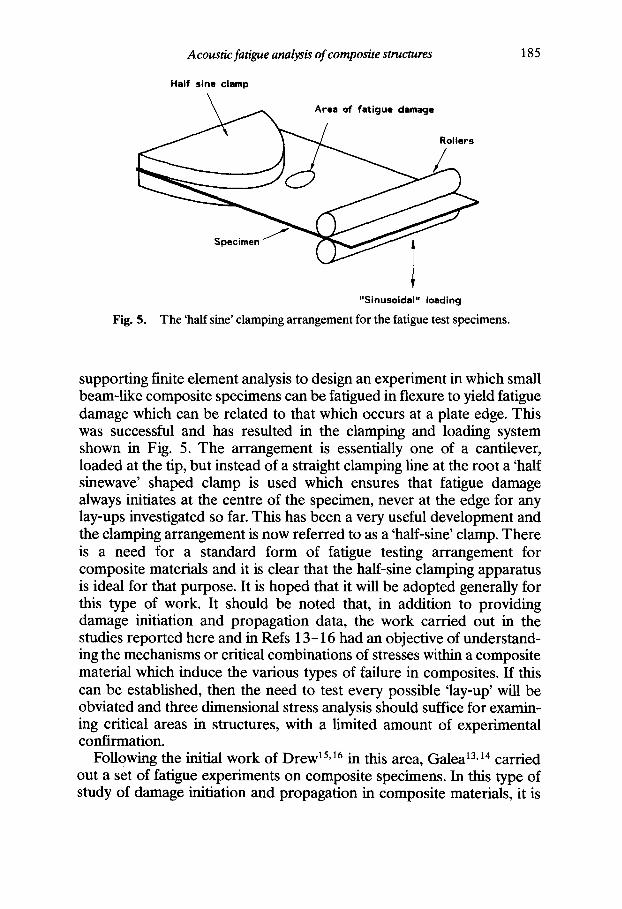
Fig. 5. The 'half sine' clamping arrangement for the fatigue test specimens.
supporting finite element analysis to design an experiment in which small beam-like composite specimens can be fatigued in flexure to yield fatigue damage which can be related to that which occurs at a plate edge. This was successful and has resulted in the clamping and loading system shown in Fig. 5. The arrangement is essentially one of a cantilever, loaded at the tip, but instead of a straight clamping line at the root a 'half sinewave' shaped clamp is used which ensures that fatigue damage always initiates at the centre of the specimen, never at the edge for any lay-ups investigated so far. This has been a very useful development and the clamping arrangement is now referred to as a 'half-sine' clamp. There is a need for a standard form of fatigue testing arrangement for composite materials and it is clear that the half-sine clamping apparatus is ideal for that purpose. It is hoped that it will be adopted generally for this type of work. It should be noted that, in addition to providing damage initiation and propagation data, the work carried out in the studies reported here and in Refs 13-16 had an objective of understand- ing the mechanisms or critical combinations of stresses within a composite material which induce the various types of failure in composites. If this can be established, then the need to test every possible 'lay-up' will be obviated and three dimensional stress analysis should suffice for examin- ing critical areas in structures, with a limited amount of experimental confirmation.
Following the initial work of Drew 15,16 in this area, Galea 13,14 carried out a set of fatigue experiments on composite specimens. In this type of study of damage initiation and propagation in composite materials, it is
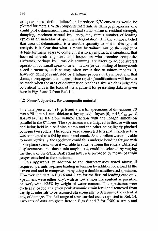
186 R. G. White
not possible to define 'failure' and produce S I N curves as would be plotted for metals. With composite materials, as damage progresses, one could plot delamination area, residual static stiffness, residual strength, damping, specimen natural frequency, etc., versus number of loading cycles as an indicator of specimen degradation. It is the author's belief that area of delamination is a sensible quantity to plot in this type of analysis. It is clear that what is meant by 'failure' will be the subject of debate for many years to come but it is likely in practical situations, that licensed aircraft engineers and inspectors who examine composite airframes, perhaps by ultrasonic scanning, are likely to accept aircraft operation with small areas of delamination (or debonding of honeycomb cored structures) such as may often occur due to minor impacts. If, however, damage is initiated by a fatigue process or by impact and that damage propagates, then appropriate repairs/modifications will have to be made when the area of delamination reaches a size which is judged to be critical. This is the basis of the argument for presenting data as given here in Figs 6 and 7 from Ref. 14.
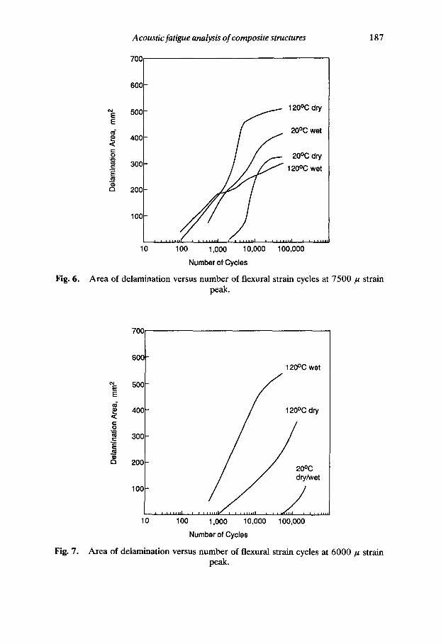
4.2 Some fatigue data for a composite material
The data presented in Figs 6 and 7 are for specimens of dimensions 70 mm x 90 mm x 1 mm thickness, lay-up eight layers [0, + 45, 0]sYu u of XAS/9146 at 0.6 fibre volume fraction with the longer dimension parallel to the 0 ° fibres. The specimens were fatigued in flexure with one end being held in a half-sine clamp and the other being lightly pinched between two rollers. The rollers were connected to a shaft, which in turn was connected to a 0.5 hp motor and crank. As the rollers were only able to move vertically, the specimen could thus undergo bending fatigue with no in-plane stress, since it was able to slide between the rollers. Different displacements, and thus strain amplitudes, could be selected by varying the throw of the crank. Peak strain level was recorded by means of strain gauges attached to the specimen.
This apparatus, in addition to the characteristics noted above, if required, permits in-plane loading in tension by addition of a load at the driven end and in compression by using a double cantilevered specimen. However, the data in Figs 6 and 7 are for the flexural loading case only. Specimens were either 'dry', with as low a moisture content as possible, or 'wet', with 1.25% by weight of water content. The specimens were cyclically loaded at a given peak dynamic strain level and removed from the rig at intervals to be scanned ultrasonically to determine the extent, if any, of damage. The full range of tests carried out is reported in Ref. 14. Two sets of data are given here in Figs 6 and 7 for 7500/~ strain and
Acoustic fatigue analysis of composite structures
7OO
187
Fig. 6.
600
500 ~ 120°C dry
400 / ~ 20°C wet < t -
O 20°C dry "~'~ 300 ~ 120°C wet
¢D
200
100
10 100 1,000 10,000 100,000 Number of Cycles
Area of delamination versus number of flexural strain cycles at 7500/~ strain peak.
700
Fig. 7.
60O 120°C wet
~E 500 E
400 120°C dry <
° = / / 2 30C C
¢3 20C 0°C
10(;
i , t * , l H I ' ¢ l = ' ' H b r ' = l = = m l I , = , , , H , ,
10 100 1,000 10,000 100,000 Number of Cycles
Area of delamination versus number of flexural strain cycles at 6000/~ strain peak.
188 R. G. White
6000 /x strain at the tip of the half-sine clamp. The whole fatigue apparatus, fully described in Ref. 14, was mounted in an environmental test chamber to enable tests to be carried out at elevated temperatures. It can be seen from Fig. 6 that, at the higher strain level, damage initiated earlier than for the lower strain level. It is clear that at 7500 /a strain, damage initiated earlier at 120°C than at 20°C but the initial damage occurred at about the same number of cycles at the higher temperature with wet or dry specimens. At 20°C, damage initiated earlier in the wet
A M a x 2 8 8 5 M a x 2322 M a x 4371
~0,, o~
M a x 2 8 8 0 M a x 874 M a x 2924 M i n - 2 8 8 0 Min 9 M i n - 2 8 6 4
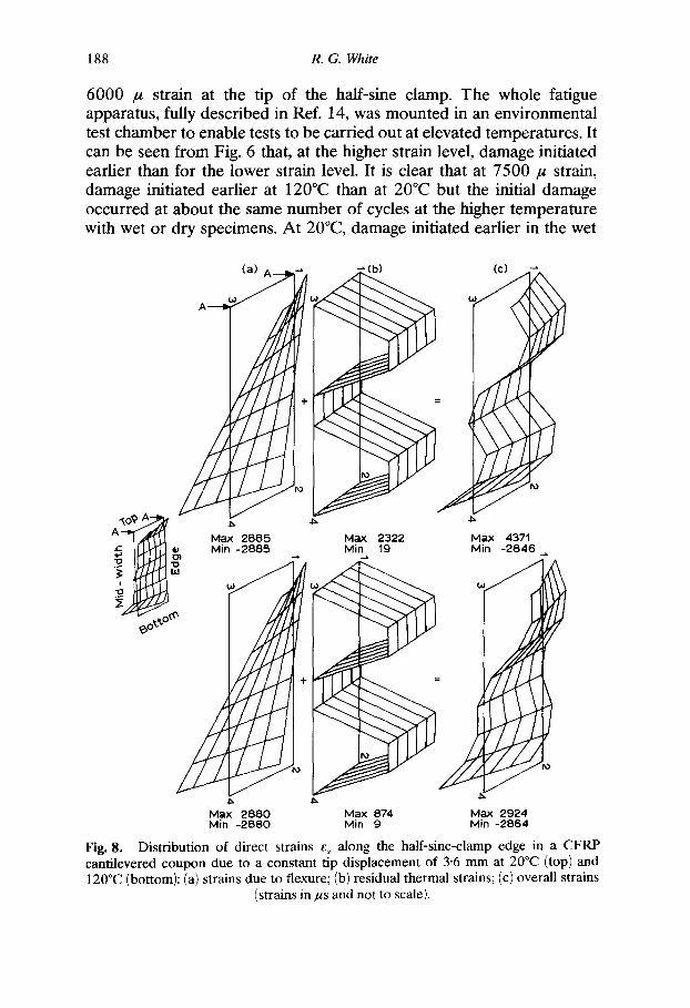
Fig. 8. Distribution of direct strains ez along the half-sine-clamp edge in a CFRP cantilevered coupon due to a constant tip displacement of 3.6 mm at 20°C (top) and 120°C (bottom): (a) strains due to flexure; (b) residual thermal strains; (c) overall strains
(strains in as and not to scale).
Acoustic fatigue analysis of composite structures 189
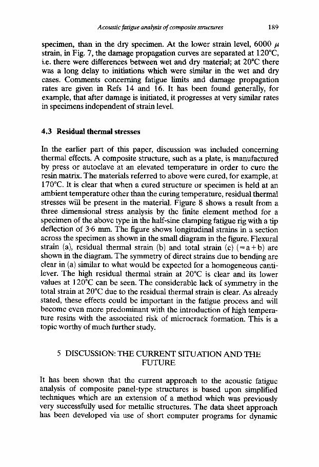
specimen, than in the dry specimen. At the lower strain level, 6000/z strain, in Fig. 7, the damage propagation curves are separated at 120°C, i.e. there were differences between wet and dry material; at 20"C there was a long delay to initiations which were similar in the wet and dry cases. Comments concerning fatigue limits and damage propagation rates are given in Refs 14 and 16. It has been found generally, for example, that after damage is initiated, it progresses at very similar rates in specimens independent of strain level.
4.3 Residual thermal stresses
In the earlier part of this paper, discussion was included concerning thermal effects. A composite structure, such as a plate, is manufactured by press or autoclave at an elevated temperature in order to cure the resin matrix. The materials referred to above were cured, for example, at 170°C. It is clear that when a cured structure or specimen is held at an ambient temperature other than the curing temperature, residual thermal stresses will be present in the material. Figure 8 shows a result from a three dimensional stress analysis by the finite element method for a specimen of the above type in the half-sine clamping fatigue rig with a tip deflection of 3.6 mm. The figure shows longitudinal strains in a section across the specimen as shown in the small diagram in the figure, Flexural strain (a), residual thermal strain (b) and total strain (c) ( = a + b ) are shown in the diagram. The symmetry of direct strains due to bending are clear in (a) similar to what would be expected for a homogeneous canti- lever. The high residual thermal strain at 20°C is clear and its lower values at 120°C can be seen. The considerable lack of symmetry in the total strain at 20°C due to the residual thermal strain is clear. As already stated, these effects could be important in the fatigue process and will become even more predominant with the introduction of high tempera- ture resins with the associated risk of microcrack formation. This is a topic worthy of much further study.
5 DISCUSSION: THE CURRENT SITUATION A N D THE FUTURE
It has been shown that the current approach to the acoustic fatigue analysis of composite panel-type structures is based upon simplified techniques which are an extension of a method which was previously very successfully used for metallic structures. The data sheet approach has been developed via use of short computer programs for dynamic

190 R. G. White
response prediction and is successful in application to plate-type structures. There is a need for experimental data for validation of the method or further empirical refinement, particularly for curved structures and sandwich constructions. Temperature effects are also worthy of further investigation.
With the need to design structures to endure more severe environ- ments in aircraft than have been encountered in the past, work is underway on nonlinear and postbuckle effects. The underlying theories in these regimes are quite complicated but it appears that simple rules for response prediction might emerge from these studies soon. If high temperature resins are necessarily introduced, the contribution of residual thermal strains to fatigue processes could become much more important, both as an influence upon the combined loading state within a material and in the formation of initial microcracks which could form sites for damage initiation.
The need for three dimensional stress/strain analysis techniques is clear and damage propagation studies should be conducted with not only the immediate objective of obtaining data for materials with specific lay- ups but to yield information which leads to establishment of criteria con- ceming critical combined stress states which would cause damage to initiate and propagate. This could obviate the need to obtain experi- mental data for all types of material. There will, however, always be the need to obtain experimental fatigue data and the 'half-sine' fatigue rig could be used generally for this purpose.
Finally, it is perhaps worthwhile re-examining the acoustic fatigue design process. The logic of using design processes which are based upon prediction of a surface strain as a fatigue indicator in a composite material may not appear to be sound. The principal reason for using this method is that it is based upon knowledge gained from, and procedures used for, the analysis of metallic aircraft structures. Other than for bonding problems to stringers, etc., fatigue in composites begins within the material and there is a need, as briefly noted above in this section, to develop methods which include the internal stress/strain states in a structure. This may not be necessary for simple constructions or materials which are quasi-isotropic but the matter is worthy of study in relation to more complicated future structural configurations.
ACKNOWLEDGEMENTS
The author would like to thank the MoD(PE) for their sponsorship of several unclassified research programmes under which most of this work
Acoustic fatigue analysis of composite structures 191
was carded out. Thanks are also due to Mr R. F. Lambert for his con- tribution in reviewing design processes, presented here, which he has developed at ESDU International.
R E F E R E N C E S
1. Lowson, M. V., Future use of advanced materials. Proceedings of the Royal Aeronautical Society Conference on Aerospace Applications of Advanced Materials, March 1989.
2. Clarkson, B. L., Fundamentals of vibration. In Noise and Vibration, ed. R. G. White & J. G. Walker. Ellis Horwood, 1982, Chapter 3.
3. Clarkson, B. L., Stresses in skin panels subjected to random acoustic loading, Aeronautical Journal of the Royal Aeronautical Society, 72 ( 1968) 1000-10.
4. ESDU, The estimation of RMS stresses in stiffened skin panels subjected to random acoustic loading. Engineering Sciences Data Unit, Item No. 72005, 1972 (amended 1984).
5. Soovere, J., Dynamic response of acoustically excited stiffened composite honeycomb panels. PhD thesis, University of Southampton, 1984.
6. White, R. G., A comparison of some statistical properties of the responses of aluminium alloy and CFRP plates to acoustic excitation. Composites, 9 (1978) 251-8.
7. Ng, C. E & White, R. G., Dynamic behaviour of postbuckled isotropic plates under in-plane compression. Journal of Sound and Vibration, 120 (1) (1988) 1-18.
8. Ng, C. E, Nonlinear and snap-through responses of curved panels to intense acoustic excitation. Journal of Aircraft, 26 (3) (1989) 281-8.
9. Benamar, R., Bennouna, M. M. K. & White, R. G., Nonlinear vibration of plates at large vibration amplitudes. Unpublished work at the Ecole Mohammadia d'Inegenieurs, Rabat and the ISVR. Lorch, D. R., Ultra high bypass aircraft sonic fatigue. Journal of Environ- mental Sciences, 32 (4) (1989) 26-34. White, R. G. & Teh, C. E., Dynamic behaviour of isotropic plates under combined acoustic excitation and static, in-plane compression. Journal of Sound and Vibration, 75 (4) ( 1981) 527-47. Ng, C. E & White, R. G., The dynamic behaviour of postbuckled com- posite plates under acoustic excitation. Composite Structures, 9 (1988) 19-35. Galea, S. C. E & White, R. G., Effect of temperature on acoustically- induced stresses in some CFRP plates. Proceedings of the Third Interna- tional Conference on Recent Advances in Structural Dynamics. Institute of Sound and Vibration Research, University of Southampton, and Flight Dynamics Laboratory of the US Air Force, Wright Aeronautical Labora- tories, Ohio, 1988. Galea, S. C. E, Effects of temperature on acoustically-induced strains and damage propagation in CFRP plates. PhD thesis, University of Southampton, 1989.
10.
11.
12.
13.
14.

192 R. G. White
15. Drew, R. C. & White, R. G., An experimental investigation into damage propagation and its effects upon dynamic properties in CFRP composite material. Proceedings of the Fourth International Conference on Composite Structures, Paisley College of Technology, 1987, pp. 245-56.
16. Drew, R. C., An investigation into damage initiation and propagation in carbon-fibre reinforced plastics. PhD thesis, University of Southampton, 1988.
APPENDIX: THE ENGINEERING SCIENCES DATA UNIT (ESDU) DESIGN GUIDE SERIES FOR PREDICTION OF ACOUSTICALLY INDUCED STRAINS IN STRUCTURES UNDER THE ACTION OF
RANDOM ACOUSTIC LOADING
A.1.
A.2.
A.3.
A.4.
A.5.
A.6.
A.7.
A.8.
A.9.
Design against fatigue. Vibration of structures under acoustic or aerodynamic excitation. Item No. 86025, ESDU International plc, London, October 1986. Estimation of the stiffnesses and apparent elastic properties of laminated flat plates. Item No. 83035, ESDU International plc, London, November 1983. Natural frequencies of rectangular, specially orthotropic laminated plates. Item No. 83036, ESDU International plc, London, November 1989. Natural frequencies of singly-curved laminated plates with simply- supported edges. Item No. 89011, ESDU International plc, London, June 1989. Natural frequencies of simply-supported sandwich panels with laminated face plates. Item No. 85037, ESDU International plc, London, December 1985. Estimation of damping in laminated and fibre-reinforced plates. Item No. 85012, ESDU International plc, London, June 1985. Estimation of RMS strain in laminated skin panels subjected to random acoustic loading. Item No. 84008, ESDU International plc, London, July 1984. Estimation of RMS strain in laminated face plates of simply- supported sandwich panels subjected to random acoustic loading. Including a simplified natural frequency prediction method. Item No. 86024, ESDU International plc, London, October 1986. Endurance of fibre-reinforced composite, laminated structural elements subjected to simulated random acoustic loading. Item No. 84027, ESDU International plc, London, November 1984.


