Accelerated Short-Term Techniques to Evaluate … The Masterbuilder - July 2012 • Accelerated...
5
248 The Masterbuilder - July 2012 • www.masterbuilder.co.in Accelerated Short-Term Techniques to Evaluate Corrosion in Reinforced Concrete Structures I n recent years an increased research effort has been focused upon corrosion of reinforcing steel in concrete and upon techniques whereby such damage can be reduced or haulted. Although the problem has been most apparent on reinforced concrete bridge decks, it also occurs on support structures (girders, piles, piers, etc), industrial plants and marine docking facilities. Steel embedded in concrete is normally subjected to an alkaline environment which subsequently passivates the steel, forming a stable oxide film. The corrosion protective properties of concrete are dependent upon maintaining an alkaline environment in intimate contact with the steel. Any condition which disrupts the environment around the steel can result in disruption of the passive film and initiate Sonjoy Deb, B.Tech,’Civil’ Associate Editor The phenomenon of corrosion of reinforcement bar in concrete is a time dependant process. Under severe environmental conditions also, it takes years for the steel reinforcement to be corroded and to cause deterioration of reinforced concrete (RC) structures. However when it becomes imperative to evaluate the relative performance of different types of steel and binder in a short time, the accelerated corrosion test can be adopted. The accelerated corrosion test does not always reproduce the actual corrosion still it can simulate to some extent the steel corrosion found in real RC structures. Concrete Corrosion
Transcript of Accelerated Short-Term Techniques to Evaluate … The Masterbuilder - July 2012 • Accelerated...

248 The Masterbuilder - July 2012 • www.masterbuilder.co.in
Accelerated Short-Term Techniques to Evaluate Corrosion in Reinforced Concrete Structures
In recent years an increased research effort has been focused upon corrosion of reinforcing steel in concrete and upon techniques whereby such damage can be
reduced or haulted. Although the problem has been most apparent on reinforced concrete bridge decks, it also occurs on support structures (girders, piles, piers, etc), industrial plants and marine docking facilities.
Steel embedded in concrete is normally subjected to an alkaline environment which subsequently passivates the steel, forming a stable oxide film. The corrosion protective properties of concrete are dependent upon maintaining an alkaline environment in intimate contact with the steel. Any condition which disrupts the environment around the steel can result in disruption of the passive film and initiate
Sonjoy Deb, B.Tech,’Civil’
Associate Editor
The phenomenon of corrosion of reinforcement bar in concrete is a time dependant process. Under severe environmental conditions also, it takes years for the steel reinforcement to be corroded and to cause deterioration of reinforced concrete (RC) structures. However when it becomes imperative to evaluate the relative performance of different types of steel and binder in a short time, the accelerated corrosion test can be adopted. The accelerated corrosion test does not always reproduce the actual corrosion still it can simulate to some extent the steel corrosion found in real RC structures.
Concrete Corrosion

www.masterbuilder.co.in • The Masterbuilder - July 2012 249
corrosion process. Marine environments and deicing salts both provide significant concentrations of chlorides which can penetrate the concrete to destroy the passive film on the reinforcing steel and reduce the pH of its environment. As the corrosion process proceeds, an accumulation of solid corrosion products forms at the metal-concrete interface. The corrosion product formed absorbs water and increases in volume. The volume of corrosion products (rust) is 2.5–6 times larger than the volume of the steel used in concrete which is the reason behind cracking and spalling of the concrete in the corrosion propagation phase as this increase in volume of rust products exerts enormous stress on the surrounding concrete. These stresses have been reported to be as high as 450MPa.
Numerous variables have been determined to influence the occurrence of reinforcing metal corrosion and concrete cracking. These may be categorized as pertaining to (i) nature of the embedded metal, (ii) nature of concrete, and (iii) nature of the environment. Chemical and electro chemical properties of the embedded metal itself are important with regard to the first category. Also included here is the influence of caotings, either metallic or inorganic, applied to the reinforcing metal. Variables in category two are the concrete mix design, including special admixtures or inhibitors, the water-cement ratio, the cement type and the depth of cover. The foremost factor of interest in the last category has been the chloride ion concentration.
Particularly lacking in the testing of reinforced concrete for its corrosion protective properties has been an accelerated test or test procedure. An exemption to this is the technique developed by Tremper et.al. in 1958, which involves exposure of a freely corroding, partially submerged reinforced specimen. The principle of this technique is that the region near or below the water line becomes anodic due to Cl- penetration; and corrosion of this area is driven by the cathodic portion of the reinforcing steel, which is in the air. A disadvantage to this test procedure is the length of the time required for data to be evolved. This is inspite of relatively small concrete cover the reinforcing metal (Approximately 0.75 inches 0r 1.9 cm). For greater cover even longer times should be required. One of the famous test that is being adopted these days is accelerated corrosion test or Impressed voltage test. The test has gained popularity because of its simplicity and more user friendly behavior.
Accelerated Corrosion Test
The setup for accelerated corrosion test (also known as impressed voltage test) is shown in Figure.1 and Figure.2. It consists of a DC power supply, two stainless steel plates, a data logger, test specimen and the container containing the required dosage of NaCl solution. Beam specimens
with a centrally embedded steel bar are used for the accelerated corrosion test. The specimens are tested at the required age after preparation. The steel bar (anode/working electrode) of the beam specimen is connected to the positive terminal and the stainless steel plates (cathode/counter electrode) are connected to the negative terminal of the DC power source. The corrosion process is initiated by applying a constant voltage to the system. The current response is continuously monitored and recorded by the data logger. In addition the specimens are daily inspected visually for the onset of cracks. The data logger is set at a sampling frequency of 1min for recording the corrosion current of the circuit. The accelerated corrosion test is terminated after cracking of the specimen when the rate of increase of corrosion current with time was negligible.
Figure 1: Schematic test set-up for accelerated corrosion test
Figure 2: Test set-up for accelerated corrosion test
Data Analysis
An important facet of this test is definition of specimen failure. In all cases test is considered to commence at the time of application of the impressed current. Specimen failure is defined as that time corresponding to onset of a large current increase. The example in Figure 3 illustrates schematically the generalized nature of current variations in the constant voltage test method. Initially it can be seen that some relatively small amplitude variations are encountered; but after that at later stage a large increase in current occurs. It is considered that this corresponds to growth of a crack within the concrete and to a corresponding decrease in electrical resistance. Crack growth is sub sequently incremental and is comprised of successive stages of propagation, which relieves tensile stresses, and
ComputerDigital multimeter withsingle channel data logger
D.C.PowerSupply
Beam Specimen
ContainerNaCl Solution
Steel Plate
Concrete Corrosion

252 The Masterbuilder - July 2012 • www.masterbuilder.co.in
arrestment, which gives rise to additional solid corrosion products accumulation. Time to failure also have been shown in this example. Figure 4 shows a cracked beam specimen after the accelerated corrosion test.
Figure 3: Corrosion Current Vs. Time Graph
Figure 4: Cracked beam specimens
Other Parameters Determined
There are various parameters of corrosion performance of reinforced concrete that can be evaluated from the accelerated corrosion test. This includes (a) free chloride content at cracking measurement, (b) mass loss measurement, (c) critical corrosion current, (d) post depassivation cracking time. Hence it can be seen that one test can give so many parameter study opportunities.
(a) Determination of free chloride content of cracked beam specimens-The beam specimens after accelerated corrosion test and half-cell potential test are analysed for free chloride content, since free chloride content is mostly responsible for corrosion of steel reinforcement in concrete. The concrete powder is collected by drilling on all four sides of the beam specimen i.e. cracked side and other three uncracked sides. The free chloride content is determined by potentiometric titration using
an automatic titrator (Make Metrohm, model: 848 Titrino plus). The titrator is equipped with a screen display that can display the chloride content automatically when appropriate inputs are fed. For determination of free chloride, three grams of the powdered concrete sample is transferred to 100ml beaker and 50ml of distilled water is added. The sample is then heated gently and thoroughly mixed by a stirrer. The solution is then cooled and filtered using Whatman No.1 filter paper and the free chloride content is then determined by titrating against 0.1 M AgNO3 solution in the automatic titrator. The results are expressed as percentage of free chloride by mass of concrete.
(b) Mass Loss analysis of the corroded reinforcement bars- After the beam specimens are corroded and the measurement of half-cell potential and free chloride ion content are taken, the beam specimens are jackhammered to remove the corroded longitudinal steel bars. The corroded bars are cleaned with a wire brush to ensure that they are free of any adhering concrete or corrosion products. After this the procedure stated in ASTM G 1-03 is adopted for the cleaning of the corroded steel specimens and for determination of mass loss. For the purpose of cleaning, the cleaning solution used is 500 ml of hydrochloric acid with 3.5 gm of hexamethylenetetramine added with reagent water to make it 1000 ml. Each specimen is cleaned several times with this solution and mass loss is noted after
Figure 5: Corroded steel bars obtained after breaking the beam specimens
2 4 6 8 10 12Time, Days
Curre
nt,M
illamps
2
46
8
10
12
14
16
18
20
Timeto
Failure
Obs
erve
dCr
ack
Concrete Corrosion
254 The Masterbuilder - July 2012 • www.masterbuilder.co.in
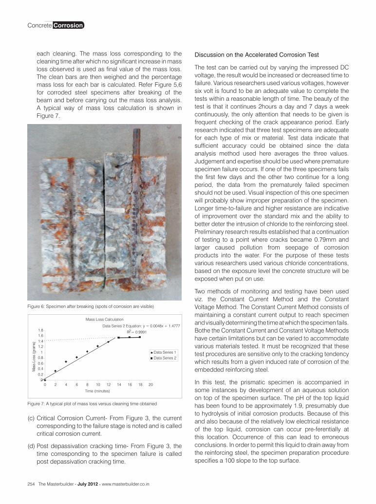
each cleaning. The mass loss corresponding to the cleaning time after which no significant increase in mass loss observed is used as final value of the mass loss. The clean bars are then weighed and the percentage mass loss for each bar is calculated. Refer Figure 5,6 for corroded steel specimens after breaking of the beam and before carrying out the mass loss analysis. A typical way of mass loss calculation is shown in Figure 7.
Discussion on the Accelerated Corrosion Test
The test can be carried out by varying the impressed DC voltage, the result would be increased or decreased time to failure. Various researchers used various voltages, however six volt is found to be an adequate value to complete the tests within a reasonable length of time. The beauty of the test is that it continues 2hours a day and 7 days a week continuously, the only attention that needs to be given is frequent checking of the crack appearance period. Early research indicated that three test specimens are adequate for each type of mix or material. Test data indicate that sufficient accuracy could be obtained since the data analysis method used here averages the three values. Judgement and expertise should be used where premature specimen failure occurs. If one of the three specimens fails the first few days and the other two continue for a long period, the data from the prematurely failed specimen should not be used. Visual inspection of this one specimen will probably show improper preparation of the specimen. Longer time-to-failure and higher resistance are indicative of improvement over the standard mix and the ability to better deter the intrusion of chloride to the reinforcing steel. Preliminary research results established that a continuation of testing to a point where cracks became 0.79mm and larger caused pollution from seepage of corrosion products into the water. For the purpose of these tests various researchers used various chloride concentrations, based on the exposure level the concrete structure will be exposed when put on use.
Two methods of monitoring and testing have been used viz. the Constant Current Method and the Constant Voltage Method. The Constant Current Method consists of maintaining a constant current output to reach specimen and visually determining the time at which the specimen fails. Bothe the Constant Current and Constant Voltage Methods have certain limitations but can be varied to accommodate various materials tested. It must be recognized that these test procedures are sensitive only to the cracking tendency which results from a given induced rate of corrosion of the embedded reinforcing steel.
In this test, the prismatic specimen is accompanied in some instances by development of an aqueous solution on top of the specimen surface. The pH of the top liquid has been found to be approximately 1.9, presumably due to hydrolysis of initial corrosion products. Because of this and also because of the relatively low electrical resistance of the top liquid, corrosion can occur pre-ferentially at this location. Occurrence of this can lead to erroneous conclusions. In order to permit this liquid to drain away from the reinforcing steel, the specimen preparation procedure specifies a 100 slope to the top surface.
Figure 6: Specimen after breaking (spots of corrosion are visible)
Mass Loss CalculationData Series 2 Equation: y = 0.0048x + 1.4777
R2= 0.9991
00.20.40.60.81
1.21.41.61.8
0 2 4 6 8 10 12 14 16 18 20Time (minutes)
MassLoss(grams)
Data Series 1Data Series 2
Figure 7: A typical plot of mass loss versus cleaning time obtained
(c) Critical Corrosion Current- From Figure 3, the current corresponding to the failure stage is noted and is called critical corrosion current.
(d) Post depassivation cracking time- From Figure 3, the time corresponding to the specimen failure is called post depassivation cracking time.
Concrete Corrosion

www.masterbuilder.co.in • The Masterbuilder - July 2012 255
Conclusion
- This Procedure provides an accelerated method of testing reinforced concrete for relative corrosion protective characteristics.
- Because of the flexibility of the method, other materials such as claddings and coatings on reinforcing steel, and concrete coatings and sealants can be tested and compared.
- This procedure should not be used to establish the life expectancy of reinforced concrete materials since the actual voltages found in the field can vary drastically. As mentioned earlier resistivity varies as the corrosion process proceeds. Changes in temperature and salinity found in the filed may greatly affect the time to failure. Until a correlation between corrosion rates in the field and in the laboratory for specific materials and mixes is established, this procedure should be used as a method for comparison only.
- If properly worked upon this test can be utilized for finding various parameters related to concrete durability. This test can also be used for comparison between various building materials. This test can be utilized for simulating various aggressive field conditions by varying the chloride content and voltage applied.
Reference
- IlkerBekir Topçu, Ahmet Raif Boga. Effect of ground granulate blast-furnace slag on corrosion performance of steel embedded in concrete. Materials and Design 2010; 31: 3358–3365.
- Mohamed Ismail, Masayasu Ohtsu. Corrosion rate of ordinary and high performance concrete subjected to chloride attack by AC impedance spectroscopy. Construction and Building Materials 2006; 20: 458–469.
- T.A. Soylev, M.G. Richardson. Corrosion inhibitors for steel in concrete: State-of-the-art report. Construction and Building Materials 2008; 22: 609– 622.
- B. Elsener. Macrocell corrosion of steel in concrete: implications for corrosion monitoring. Cement & Concrete Composites 2002; 24: 65–72.
- A. Poursaee, A. Laurent, C.M. Hansson. Corrosion of steel bars in OPC mortar exposed to NaCl, MgCl2 and CaCl2: Macro and micro-cell corrosion perspective. Cement and Concrete Research 2010; 40: 426–430.
- BuluPradhan, B. Bhattacharjee. Performance evaluation of rebar in chloride contaminated concrete by corrosion rate. Construction and Building Materials 2009; 23 2346–2356.
- A. Poursaee, C.M. Hansson. Reinforcing steel passivation in mortar and pore solution. Cement and Concrete Research 2007; 37: 1127–1133.
- Marco Ormellese, Luciano Lazzari, Sara Goidanich, Gabriele
Fumagalli, Andrea Brenna. A study of organic substances as inhibitors for chloride-induced corrosion in concrete. Corrosion Science 2009; 51: 2959–2968.
- Bulu Pradhan, B. Bhattacharjee. Corrosion zones of rebar in chloride contaminated concrete through potentiostatic study in concrete powder solution extracts. Corrosion Science 2007; 49: 3935–3952.
- A.A.A. Hassan, K.M.A. Hossain, M. Lachemi. Corrosion resistance of self-consolidating concrete in full-scale reinforced beams. Cement & Concrete Composites 2009; 31: 29–38.
- IlkerBekirTopçu,AhmetRaifBoğa,FatihOnurHocaoğlu.Modelingcorrosion currents of reinforced concrete using ANN. Automation in Construction 2009; 18: 145–152.
- Ha Minh, Hiroshi Mutsuyoshi, KyojiNiitani. Influence of grouting condition on crack and load-carrying capacity of post-tensioned concrete beam due to chloride-induced corrosion. Construction and Building Materials 2007; 21: 1568–1575.
- M.M. Al-Zahrani , S.U. Al-Dulaijan, M. Ibrahim, H. Saricimen, F.M. Sharif. Effect of waterproofing coatings on steel reinforcement corrosion and physical properties of concrete. Cement & Concrete Composites 2002; 24: 127–137.
- Abdul-Hamid J. Al-Tayyib and Mesfer M. Al-Zahrani. Corrosion of Steel Reinforcement in Polypropylene Fiber Reinforced Concrete Structures. ACI Material Journal 1990; 87: 108-113.
- Mustafa Sahmaran, Victor C. Li, and Carmen Andrade.Corrosion Resistance Performance of Steel-Reinforced Engineered Cementitious Composite Beams. ACI Material Journal 2008; 105: 243-250.
- Tae-Hyun Ha, SrinivasanMuralidharan, Jeong-HyoBae, Yoon-Cheol Ha, Hyun-Goo Lee, Kyung-Wha Park, Dae-Kyeong Kim. Accelerated short-term techniques to evaluate the corrosion performance of steel in fly ash blended concrete. Building and Environment 2007; 42: 78–85.
- ErhanGuneyisi, TuranOzturan, Mehmet Gesoglu. A study on reinforcement corrosion and related properties of plain and blended cement concretes under different curing conditions. Cement & Concrete Composites 2005; 27: 449–461.
- M. Maslehuddin, M.M. Al-Zahrani, S.U. Al-Dulaijan, Abdulquddus, S. Rehman, S.N. Ahsan. Effect of steel manufacturing process and atmospheric corrosion on the corrosion-resistance of steel bars in concrete. Cement & Concrete Composites 2002; 24: 151–158.
- ASTM C 876. Standard test method for half-cell potentials of uncoated reinforcing steel in concrete.Annual Book of ASTM Standards, American Society for Testing and Materials; 1991.
- IS 383-1970 (Reaffirmed 2002).Specification for coarse and fine aggregates from natural sources for concrete. New Delhi: Bureau of Indian Standards.
- Neville AM, Brooks JJ. Concrete technology. Delhi: Pearson Education; 2004.
- ASTM G 1-03. Standard practice for preparing, cleaning, and evaluating corrosion test specimens.West Conshohocken, PA; 2003.
Concrete Corrosion