
acad_3
10
MATCHING PROPERTIES OF OTHER OBJECTS You can copy some or all properties of one object to one or more objects using MATCHPROP. Properties that can be copied include color, layer, linetype, linetype scale, lineweight, thickness, plot style, and in some cases, dimension, text, and hatch. COPYING THE OBJECTS To copy objects within a drawing, create a selection set and specify a start point and an endpoint for the copy. These points are called the base point and the second point of displacement, respectively, and can be anywhere within the drawing. Command: Copy OFFSETTING THE OBJECTS Offsetting creates a new object that is similar to a selected object but at a specified distance. You can offset lines, arcs, circles, 2D polylines, ellipses, elliptical arcs, xlines, rays, and planar splines. Offsetting circles creates larger or smaller circles depending on the offset side. Offsetting outside the perimeter creates a larger circle. Offsetting inside creates a smaller one. Command: Offset MIRRORING THE OBJECTS You mirror objects around a mirror line, which you define with two points, as shown in the following illustration. You can delete or retain the original objects. Mirroring works in any plane parallel to the XY plane of the current UCS. Although you can mirror a viewport object in paper space, doing so has no effect on its model space view or model space objects. Command: Mirror
-
Upload
royalaryans -
Category
Documents
-
view
213 -
download
0
Transcript of acad_3

MATCHING PROPERTIES OF OTHER OBJECTS
You can copy some or all properties of one object to one or more objects using MATCHPROP. Properties that can be copied include color, layer, linetype, linetype scale, lineweight, thickness, plot style, and in some cases, dimension, text, and hatch. COPYING THE OBJECTS
To copy objects within a drawing, create a selection set and specify a start point and an endpoint for the copy. These points are called the base point and the second point of displacement, respectively, and can be anywhere within the drawing. Command: Copy
OFFSETTING THE OBJECTS
Offsetting creates a new object that is similar to a selected object but at a specified distance. You can offset lines, arcs, circles, 2D polylines, ellipses, elliptical arcs, xlines, rays, and planar splines. Offsetting circles creates larger or smaller circles depending on the offset side. Offsetting outside the perimeter creates a larger circle. Offsetting inside creates a smaller one.
Command: Offset
MIRRORING THE OBJECTS
You mirror objects around a mirror line, which you define with two points, as shown in the following illustration. You can delete or retain the original objects. Mirroring works in any plane parallel to the XY plane of the current UCS. Although you can mirror a viewport object in paper space, doing so has no effect on its model space view or model space objects. Command: Mirror

ARRYING OBJECTS
You can copy an object or selection set in polar or rectangular arrays (patterns). For polar arrays, you control the number of copies of the object and whether the copies are rotated. For rectangular arrays, you control the number of rows and columns and the distance between them. Command: Array

MOVING THE OBJECTS
When you move objects, you can rotate or align them or move them without changing Orientation or size. Use snap mode, coordinates, grips, and object snap modes to move objects with precision. In the following example, you move the window. Command: Move
ROTATING OBJECTS
You rotate objects by choosing a base point and a relative or absolute rotation angle. Specify a relative angle to rotate the object from its current orientation around the base point by that angle. Whether the objects are rotated counterclockwise or clockwise depends on the Direction Control setting in the Units Control dialog box. Specify absolute angles to rotate objects from the current angle to a new absolute angle.
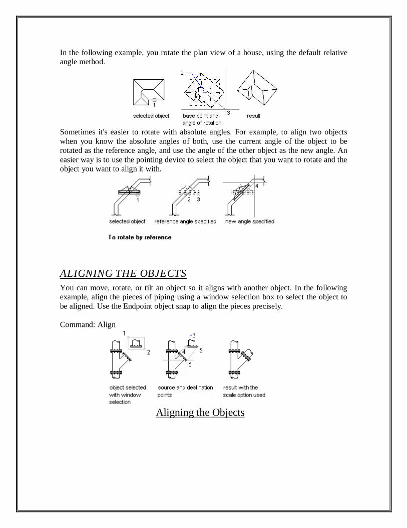
In the following example, you rotate the plan view of a house, using the default relative angle method.
Sometimes it's easier to rotate with absolute angles. For example, to align two objects when you know the absolute angles of both, use the current angle of the object to be rotated as the reference angle, and use the angle of the other object as the new angle. An easier way is to use the pointing device to select the object that you want to rotate and the object you want to align it with.
ALIGNING THE OBJECTS
You can move, rotate, or tilt an object so it aligns with another object. In the following example, align the pieces of piping using a window selection box to select the object to be aligned. Use the Endpoint object snap to align the pieces precisely. Command: Align
Aligning the Objects

ERASING THE OBJECTS
You can erase objects using all the available selection methods. In the following example, you use window selection to erase a section of piping. Only objects enclosed by the window are erased.
Command: Erase STRETCHING THE OBJECTS
To stretch an object, you specify a base point for the stretch and then two points of displacement. You can also select the object with a crossing selection and combine grip editing with object snaps, grip snaps, grid snaps, and relative coordinate entry to stretch with greater accuracy.
Command: Stretch Moving by Stretching: In the following example, you move a door from one part of a wall to another by stretching. Turning on Ortho mode helps you move the object in a straight line.
STRETCHING BY GRIPS
You stretch an object by moving selected grips to new locations. Some grips move the object rather than stretching it. This is true of grips on text objects, blocks, midpoints of lines, centers of circles, centers of ellipses, and point objects.
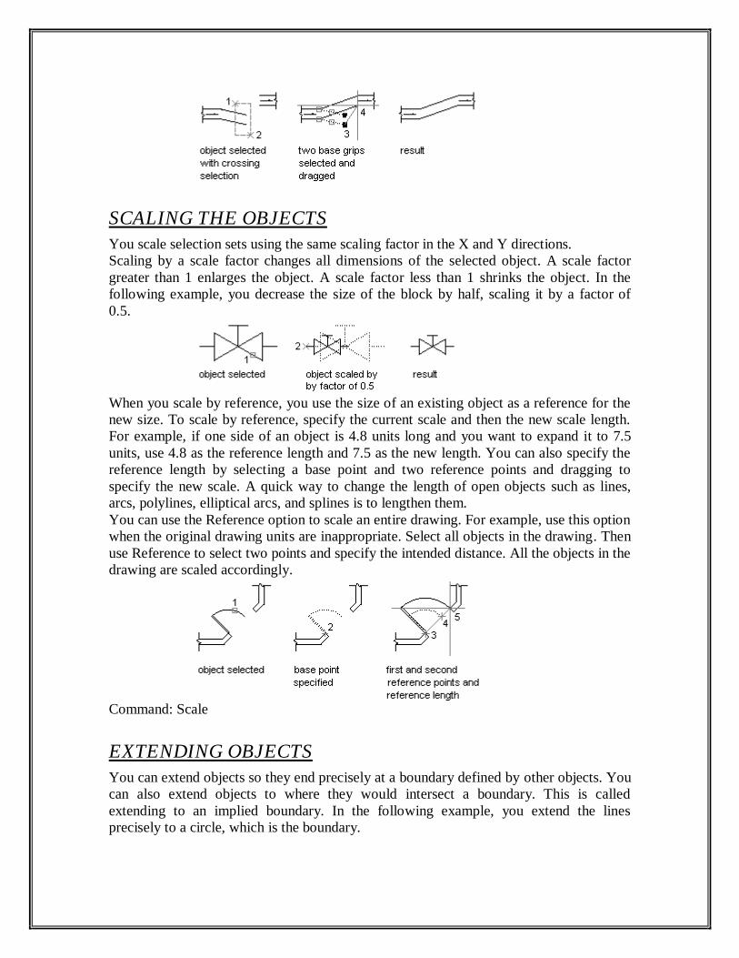
SCALING THE OBJECTS
You scale selection sets using the same scaling factor in the X and Y directions. Scaling by a scale factor changes all dimensions of the selected object. A scale factor greater than 1 enlarges the object. A scale factor less than 1 shrinks the object. In the following example, you decrease the size of the block by half, scaling it by a factor of 0.5.
When you scale by reference, you use the size of an existing object as a reference for the new size. To scale by reference, specify the current scale and then the new scale length. For example, if one side of an object is 4.8 units long and you want to expand it to 7.5 units, use 4.8 as the reference length and 7.5 as the new length. You can also specify the reference length by selecting a base point and two reference points and dragging to specify the new scale. A quick way to change the length of open objects such as lines, arcs, polylines, elliptical arcs, and splines is to lengthen them. You can use the Reference option to scale an entire drawing. For example, use this option when the original drawing units are inappropriate. Select all objects in the drawing. Then use Reference to select two points and specify the intended distance. All the objects in the drawing are scaled accordingly.
Command: Scale EXTENDING OBJECTS
You can extend objects so they end precisely at a boundary defined by other objects. You can also extend objects to where they would intersect a boundary. This is called extending to an implied boundary. In the following example, you extend the lines precisely to a circle, which is the boundary.
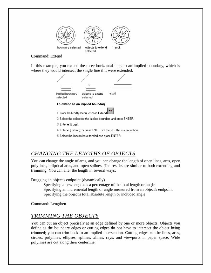
Command: Extend In this example, you extend the three horizontal lines to an implied boundary, which is where they would intersect the single line if it were extended.
CHANGING THE LENGTHS OF OBJECTS
You can change the angle of arcs, and you can change the length of open lines, arcs, open polylines, elliptical arcs, and open splines. The results are similar to both extending and trimming. You can alter the length in several ways: Dragging an object's endpoint (dynamically) Specifying a new length as a percentage of the total length or angle Specifying an incremental length or angle measured from an object's endpoint Specifying the object's total absolute length or included angle Command: Lengthen TRIMMING THE OBJECTS
You can cut an object precisely at an edge defined by one or more objects. Objects you define as the boundary edges or cutting edges do not have to intersect the object being trimmed; you can trim back to an implied intersection. Cutting edges can be lines, arcs, circles, polylines, ellipses, splines, xlines, rays, and viewports in paper space. Wide polylines are cut along their centerline.

Command: Trim
An implied intersection is the point where two objects would intersect if they were extended. You can trim objects using their implied intersection as the cutting edge. In the following example, you trim the vertical wall back to its implied intersection with the horizontal wall.
An object can be one of the cutting edges and one of the objects being trimmed. For example, in the light fixture illustrated, the circle is a cutting edge for the construction lines and is also being trimmed.
When trimming complex objects, using different selection methods can help you choose the right cutting edges and objects to trim. In the following example, the cutting edges are selected with a crossing window.
In the following example, fence selection is used to select a series of objects for trimming.
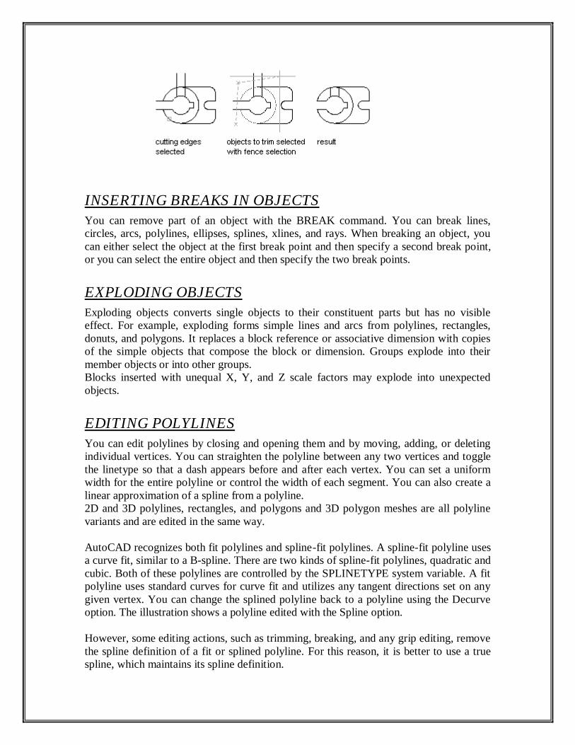
INSERTING BREAKS IN OBJECTS
You can remove part of an object with the BREAK command. You can break lines, circles, arcs, polylines, ellipses, splines, xlines, and rays. When breaking an object, you can either select the object at the first break point and then specify a second break point, or you can select the entire object and then specify the two break points. EXPLODING OBJECTS
Exploding objects converts single objects to their constituent parts but has no visible effect. For example, exploding forms simple lines and arcs from polylines, rectangles, donuts, and polygons. It replaces a block reference or associative dimension with copies of the simple objects that compose the block or dimension. Groups explode into their member objects or into other groups. Blocks inserted with unequal X, Y, and Z scale factors may explode into unexpected objects. EDITING POLYLINES
You can edit polylines by closing and opening them and by moving, adding, or deleting individual vertices. You can straighten the polyline between any two vertices and toggle the linetype so that a dash appears before and after each vertex. You can set a uniform width for the entire polyline or control the width of each segment. You can also create a linear approximation of a spline from a polyline. 2D and 3D polylines, rectangles, and polygons and 3D polygon meshes are all polyline variants and are edited in the same way. AutoCAD recognizes both fit polylines and spline-fit polylines. A spline-fit polyline uses a curve fit, similar to a B-spline. There are two kinds of spline-fit polylines, quadratic and cubic. Both of these polylines are controlled by the SPLINETYPE system variable. A fit polyline uses standard curves for curve fit and utilizes any tangent directions set on any given vertex. You can change the splined polyline back to a polyline using the Decurve option. The illustration shows a polyline edited with the Spline option. However, some editing actions, such as trimming, breaking, and any grip editing, remove the spline definition of a fit or splined polyline. For this reason, it is better to use a true spline, which maintains its spline definition.
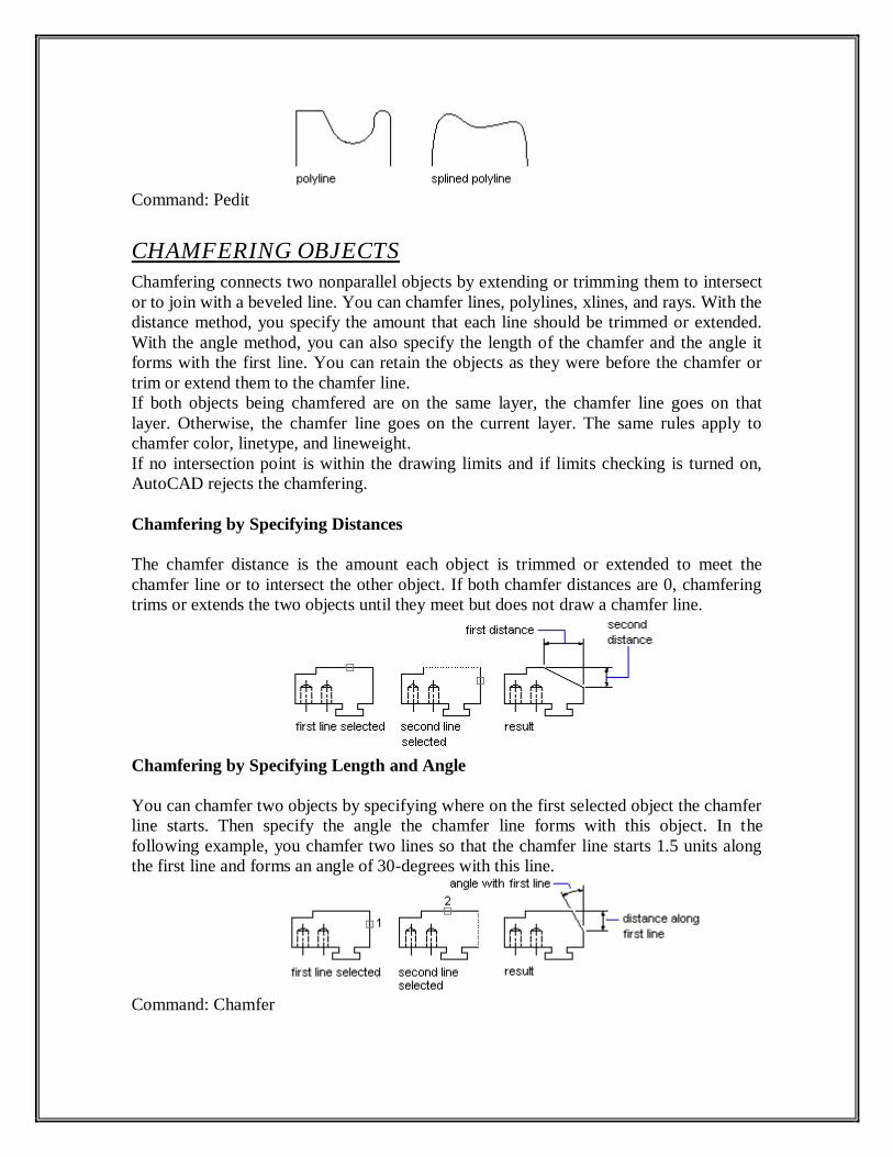
Command: Pedit CHAMFERING OBJECTS
Chamfering connects two nonparallel objects by extending or trimming them to intersect or to join with a beveled line. You can chamfer lines, polylines, xlines, and rays. With the distance method, you specify the amount that each line should be trimmed or extended. With the angle method, you can also specify the length of the chamfer and the angle it forms with the first line. You can retain the objects as they were before the chamfer or trim or extend them to the chamfer line. If both objects being chamfered are on the same layer, the chamfer line goes on that layer. Otherwise, the chamfer line goes on the current layer. The same rules apply to chamfer color, linetype, and lineweight. If no intersection point is within the drawing limits and if limits checking is turned on, AutoCAD rejects the chamfering. Chamfering by Specifying Distances The chamfer distance is the amount each object is trimmed or extended to meet the chamfer line or to intersect the other object. If both chamfer distances are 0, chamfering trims or extends the two objects until they meet but does not draw a chamfer line.
Chamfering by Specifying Length and Angle You can chamfer two objects by specifying where on the first selected object the chamfer line starts. Then specify the angle the chamfer line forms with this object. In the following example, you chamfer two lines so that the chamfer line starts 1.5 units along the first line and forms an angle of 30-degrees with this line.
Command: Chamfer


