ABSTRACT FLEMING, JASON GRAHAM. Novel Simulation of
288
ABSTRACT FLEMING, JASON GRAHAM. Novel Simulation of Anaerobic Digestion Using Computational Fluid Dynamics. (Under the direction of Richard R. Johnson.) In an effort to optimize the economy and performance of covered anaerobic reactor systems, a comprehensive dynamic and mechanistic model was created to simulate the constituent processes of full-scale anaerobic digestion. These processes included the following: bulk fluid motion, sedimenta- tion, bubble mixing, bubble entrainment, buoyant mixing, advection, biological reactions, internal heat transfer, and heat exchange with the environment. This model contrasted with conventional models that assumed uniform concentrations and temperature throughout the reacting medium. Novel numerical simulation techniques were developed to simulate the heat and mass transfer re- sulting from two phase gas-liquid flow and unsteady buoyancy driven flow. The complete model was implemented in a computer code called LagoonSim3D. Three years of performance data from a full-scale covered anaerobic digestion system in central North Carolina were used to quantify unknown parameters as well as validate the LagoonSim3D software. The LagoonSim3D software predicted the temperature of the covered lagoon within 5.7% and the dynamic monthly gas production within 11%. The external convective heat transfer co- efficient was found to be h ∞ = 17.5V +6.0W/m 2 K where V was the wind speed in m/s. The convective heat transfer coefficient of the gas gap between the cover and the slurry was found to be h = 10 W/m 2 K. The average particle settling velocity was found to be v s =0.02 cm/s. These previously unknown parameters were important for the design of future anaerobic digestion systems.
Transcript of ABSTRACT FLEMING, JASON GRAHAM. Novel Simulation of

ABSTRACT
FLEMING, JASON GRAHAM. Novel Simulation of Anaerobic Digestion Using Computational
Fluid Dynamics. (Under the direction of Richard R. Johnson.)
In an effort to optimize the economy and performance of covered anaerobic reactor systems, a
comprehensive dynamic and mechanistic model was created to simulate the constituent processes of
full-scale anaerobic digestion. These processes included the following: bulk fluid motion, sedimenta-
tion, bubble mixing, bubble entrainment, buoyant mixing, advection, biological reactions, internal
heat transfer, and heat exchange with the environment. This model contrasted with conventional
models that assumed uniform concentrations and temperature throughout the reacting medium.
Novel numerical simulation techniques were developed to simulate the heat and mass transfer re-
sulting from two phase gas-liquid flow and unsteady buoyancy driven flow. The complete model was
implemented in a computer code called LagoonSim3D.
Three years of performance data from a full-scale covered anaerobic digestion system in central
North Carolina were used to quantify unknown parameters as well as validate the LagoonSim3D
software. The LagoonSim3D software predicted the temperature of the covered lagoon within 5.7%
and the dynamic monthly gas production within 11%. The external convective heat transfer co-
efficient was found to be h∞ = 17.5V + 6.0 W/m2K where V was the wind speed in m/s. The
convective heat transfer coefficient of the gas gap between the cover and the slurry was found to
be h = 10 W/m2K. The average particle settling velocity was found to be vs = 0.02 cm/s. These
previously unknown parameters were important for the design of future anaerobic digestion systems.

The validated LagoonSim3D model was used to determine the effect of design changes on reactor
performance. In part, it was found that the case study system had at least twice the required volume,
and that the depth was optimal. It was also found that the performance of the case study system
could be improved by cutting the flush water volume in half. It was concluded that the LagoonSim3D
software enabled a flexible and general evaluation of covered anaerobic lagoon designs that was not
possible with previously available complete-mix models.

NOVEL SIMULATION OF ANAEROBIC DIGESTION
USING COMPUTATIONAL FLUID DYNAMICS
by
JASON GRAHAM FLEMING
A dissertation submitted to the Graduate Faculty of
North Carolina State University
in partial fulfillment of the
requirements for the Degree of
Doctor of Philosophy
MECHANICAL ENGINEERING
Raleigh, NC
2002
APPROVED BY:
Richard R. Johnson Kevin M. Lyons
Dissertation Committee Chair
Herbert M. Eckerlin James W. Leach
Jiayang Cheng

ii
BIOGRAPHY
Jason Fleming graduated from Youngstown State University with a Bachelor of Engineering
degree in Mechanical Engineering in 1994. He then entered Texas A&M University in pursuit of a
Master of Science degree in Mechanical Engineering. Upon graduation from Texas A&M Univer-
sity in 1997, he initiated studies at North Carolina State University in pursuit of a Doctorate of
Philosophy in Mechanical Engineering.

iii
ACKNOWLEDGMENTS
First, I would like to thank my wife and colleague Janelle V.R. Fleming. I would also like
to thank my most excellent advisor, Dr. Richard R. Johnson. The support of my dissertation
committee—Dr. Jiayang Cheng, Dr. Herb Eckerlin, Dr. Jim Leach, and Dr. Kevin Lyons—is much
appreciated. The loan of six thermistors from Dr. Richard Luettich is gratefully acknowledged.
I would like to acknowledge the financial and equipment support of SGI and the North Carolina
Supercomputer Center. Finally, I would like to give thanks for the love and encouragement provided
by my mom.

iv
TABLE OF CONTENTS
LIST OF FIGURES . . . . . . . . . . . . . . . . . . . . . . . . . . . . . . . . . . . . . . . . . . . . . . . . . . . . . . . . . . . . . . . . . . . . . vii
LIST OF TABLES . . . . . . . . . . . . . . . . . . . . . . . . . . . . . . . . . . . . . . . . . . . . . . . . . . . . . . . . . . . . . . . . . . . . . . ix
NOMENCLATURE . . . . . . . . . . . . . . . . . . . . . . . . . . . . . . . . . . . . . . . . . . . . . . . . . . . . . . . . . . . . . . . . . . . . . x
I INTRODUCTION
Background . . . . . . . . . . . . . . . . . . . . . . . . . . . . . . . . . . . . . . . . . . . . . . . . . . . . . . . . . . . . . . . . . . . . . .1
Objectives . . . . . . . . . . . . . . . . . . . . . . . . . . . . . . . . . . . . . . . . . . . . . . . . . . . . . . . . . . . . . . . . . . . . . . . 3
Summary . . . . . . . . . . . . . . . . . . . . . . . . . . . . . . . . . . . . . . . . . . . . . . . . . . . . . . . . . . . . . . . . . . . . . . . . 4
II LITERATURE REVIEW
Summary of Tasks . . . . . . . . . . . . . . . . . . . . . . . . . . . . . . . . . . . . . . . . . . . . . . . . . . . . . . . . . . . . . . . 6
Complete Mixing Assumption . . . . . . . . . . . . . . . . . . . . . . . . . . . . . . . . . . . . . . . . . . . . . . . . . . . . 6
Fluid Dynamics . . . . . . . . . . . . . . . . . . . . . . . . . . . . . . . . . . . . . . . . . . . . . . . . . . . . . . . . . . . . . . . . . . 8
Heat Transfer . . . . . . . . . . . . . . . . . . . . . . . . . . . . . . . . . . . . . . . . . . . . . . . . . . . . . . . . . . . . . . . . . . . . 9
Advection . . . . . . . . . . . . . . . . . . . . . . . . . . . . . . . . . . . . . . . . . . . . . . . . . . . . . . . . . . . . . . . . . . . . . . . 10
Eulerian Two Phase Gas Liquid Flow . . . . . . . . . . . . . . . . . . . . . . . . . . . . . . . . . . . . . . . . . . . . 11
Two Phase Solid Liquid Granular Flow . . . . . . . . . . . . . . . . . . . . . . . . . . . . . . . . . . . . . . . . . . .14
Sedimentation . . . . . . . . . . . . . . . . . . . . . . . . . . . . . . . . . . . . . . . . . . . . . . . . . . . . . . . . . . . . . . . . . . . 14
Biodegradation . . . . . . . . . . . . . . . . . . . . . . . . . . . . . . . . . . . . . . . . . . . . . . . . . . . . . . . . . . . . . . . . . . 16
Statistics . . . . . . . . . . . . . . . . . . . . . . . . . . . . . . . . . . . . . . . . . . . . . . . . . . . . . . . . . . . . . . . . . . . . . . . . 23
Summary . . . . . . . . . . . . . . . . . . . . . . . . . . . . . . . . . . . . . . . . . . . . . . . . . . . . . . . . . . . . . . . . . . . . . . . . 24
III IMPLEMENTATION OF SELECTED SOLUTION TECHNIQUES
Overview of the Model . . . . . . . . . . . . . . . . . . . . . . . . . . . . . . . . . . . . . . . . . . . . . . . . . . . . . . . . . . . 25
Fluid Dynamics . . . . . . . . . . . . . . . . . . . . . . . . . . . . . . . . . . . . . . . . . . . . . . . . . . . . . . . . . . . . . . . . . . 27
Sedimentation . . . . . . . . . . . . . . . . . . . . . . . . . . . . . . . . . . . . . . . . . . . . . . . . . . . . . . . . . . . . . . . . . . . 28
Heat Transfer . . . . . . . . . . . . . . . . . . . . . . . . . . . . . . . . . . . . . . . . . . . . . . . . . . . . . . . . . . . . . . . . . . . . 28

v
Mixing . . . . . . . . . . . . . . . . . . . . . . . . . . . . . . . . . . . . . . . . . . . . . . . . . . . . . . . . . . . . . . . . . . . . . . . . . . .31
Biological Reaction . . . . . . . . . . . . . . . . . . . . . . . . . . . . . . . . . . . . . . . . . . . . . . . . . . . . . . . . . . . . . . 35
Summary . . . . . . . . . . . . . . . . . . . . . . . . . . . . . . . . . . . . . . . . . . . . . . . . . . . . . . . . . . . . . . . . . . . . . . . . 36
IV VALIDATION AND SENSITIVITY ANALYSIS
Case Study System Description . . . . . . . . . . . . . . . . . . . . . . . . . . . . . . . . . . . . . . . . . . . . . . . . . . 37
Parameter Estimation . . . . . . . . . . . . . . . . . . . . . . . . . . . . . . . . . . . . . . . . . . . . . . . . . . . . . . . . . . . .41
Validation . . . . . . . . . . . . . . . . . . . . . . . . . . . . . . . . . . . . . . . . . . . . . . . . . . . . . . . . . . . . . . . . . . . . . . . 42
Sensitivity Analysis . . . . . . . . . . . . . . . . . . . . . . . . . . . . . . . . . . . . . . . . . . . . . . . . . . . . . . . . . . . . . . 48
External Convective Heat Transfer Coefficient . . . . . . . . . . . . . . . . . . . . . . . . . . . . . 49
Internal Convective Heat Transfer Coefficient . . . . . . . . . . . . . . . . . . . . . . . . . . . . . . 50
Sherwood Number . . . . . . . . . . . . . . . . . . . . . . . . . . . . . . . . . . . . . . . . . . . . . . . . . . . . . . . . 51
Bubble Mix Factor . . . . . . . . . . . . . . . . . . . . . . . . . . . . . . . . . . . . . . . . . . . . . . . . . . . . . . . . 52
Settling Velocity . . . . . . . . . . . . . . . . . . . . . . . . . . . . . . . . . . . . . . . . . . . . . . . . . . . . . . . . . . 54
Mesh Resolution . . . . . . . . . . . . . . . . . . . . . . . . . . . . . . . . . . . . . . . . . . . . . . . . . . . . . . . . . . 55
Summary . . . . . . . . . . . . . . . . . . . . . . . . . . . . . . . . . . . . . . . . . . . . . . . . . . . . . . . . . . . . . . . . . . . . . . . . 57
V APPLICATION TO DESIGN MODIFICATIONS
Overview . . . . . . . . . . . . . . . . . . . . . . . . . . . . . . . . . . . . . . . . . . . . . . . . . . . . . . . . . . . . . . . . . . . . . . . . 59
Increased Load . . . . . . . . . . . . . . . . . . . . . . . . . . . . . . . . . . . . . . . . . . . . . . . . . . . . . . . . . . . . . . . . . . .59
Water Management . . . . . . . . . . . . . . . . . . . . . . . . . . . . . . . . . . . . . . . . . . . . . . . . . . . . . . . . . . . . . . 62
Modified Depth with Constant HRT . . . . . . . . . . . . . . . . . . . . . . . . . . . . . . . . . . . . . . . . . . . . . .64
Reduction in HRT with Constant Depth . . . . . . . . . . . . . . . . . . . . . . . . . . . . . . . . . . . . . . . . . .66
Summary . . . . . . . . . . . . . . . . . . . . . . . . . . . . . . . . . . . . . . . . . . . . . . . . . . . . . . . . . . . . . . . . . . . . . . . . 67
VI CONCLUSIONS AND RECOMMENDATIONS
Conclusions . . . . . . . . . . . . . . . . . . . . . . . . . . . . . . . . . . . . . . . . . . . . . . . . . . . . . . . . . . . . . . . . . . . . . . 69
Recommendations . . . . . . . . . . . . . . . . . . . . . . . . . . . . . . . . . . . . . . . . . . . . . . . . . . . . . . . . . . . . . . . .71

vi
REFERENCES . . . . . . . . . . . . . . . . . . . . . . . . . . . . . . . . . . . . . . . . . . . . . . . . . . . . . . . . . . . . . . . . . . . . . . . . . . . . . .72
BIBLIOGRAPHY . . . . . . . . . . . . . . . . . . . . . . . . . . . . . . . . . . . . . . . . . . . . . . . . . . . . . . . . . . . . . . . . . . . . . . . . . . . 74
APPENDIX A: BASIC ECONOMIC DATA FOR CASE STUDY SYSTEM . . . . . . . . . . . . . . . . . . 78
APPENDIX B: MEASURED DATA . . . . . . . . . . . . . . . . . . . . . . . . . . . . . . . . . . . . . . . . . . . . . . . . . . . . . . . . . 79
APPENDIX C: SAMPLE INPUT FILE . . . . . . . . . . . . . . . . . . . . . . . . . . . . . . . . . . . . . . . . . . . . . . . . . . . . . .85
APPENDIX D: ESSENTIAL SOURCE CODE . . . . . . . . . . . . . . . . . . . . . . . . . . . . . . . . . . . . . . . . . . . . . . .88

vii
LIST OF FIGURES
1 Open lagoons are not optimal. . . . . . . . . . . . . . . . . . . . . . . . . . . . . . . . . . . . . . . . . . . . . . . . . . 1
2 This is an anaerobic digestion plant treating agricultural waste. . . . . . . . . . . . . . . . . 2
3 The complete mix model was appropriate at the bench scale . . . . . . . . . . . . . . . . . . . . 3
4 The anaerobic digestion process without complete mixing . . . . . . . . . . . . . . . . . . . . . . .5
5 First order advection algorithm. . . . . . . . . . . . . . . . . . . . . . . . . . . . . . . . . . . . . . . . . . . . . . . . .10
6 Maximum specific growth rate increased with increasing temperature . . . . . . . . . . . 20
7 Temperature dependence curve . . . . . . . . . . . . . . . . . . . . . . . . . . . . . . . . . . . . . . . . . . . . . . . . .21
8 The solution procedure contains a central loop. . . . . . . . . . . . . . . . . . . . . . . . . . . . . . . . . .25
9 The measured pit temperature data was highly variable in winter . . . . . . . . . . . . . . . 29
10 The case study reactor was an in ground covered anaerobic digester . . . . . . . . . . . . .37
11 The Barham Farm uses biogas to provide electricity as well as heating . . . . . . . . . . 37
12 The simulated temperature tracked closely with the measured data. . . . . . . . . . . . . 43
13 The simulated temperature was within ±10% of the measured data. . . . . . . . . . . . . 43
14 Measured bigoas production showed two distinct performance regimes. . . . . . . . . . .44
15 The relative monthly error in the biogas solution was 10.9% . . . . . . . . . . . . . . . . . . . . 45
16 The relative monthly error in the biogas solution was 54.5% . . . . . . . . . . . . . . . . . . . . 45
17 The relative monthly error in the biogas solution was 25.1% . . . . . . . . . . . . . . . . . . . . 47
18 Effect of varying h∞ intercept on the center temperature solution . . . . . . . . . . . . . . .49
19 Effect of varying hgap on center temperature solution. . . . . . . . . . . . . . . . . . . . . . . . . . . 50
20 Effect of varying hgap on biogas solution. . . . . . . . . . . . . . . . . . . . . . . . . . . . . . . . . . . . . . . .50
21 Increasing Shent caused the magnitude of the biogas solution to increase slightly. 51
22 Increasing fbub increased the amplitude of the biogas solution. . . . . . . . . . . . . . . . . . 52
23 Cutting the bubble mixing in half reduced the reaction rate. . . . . . . . . . . . . . . . . . . . .52
24 Doubling the bubble mixing increased the reaction rate for most of the year. . . . .52
25 Faster settling velocity shifted the phase of the biogas solution by two weeks . . . . 54

viii
26 Slower settling velocity spread the reactants across the reactor . . . . . . . . . . . . . . . . . .54
27 Fast settling velocity caused reactants to pool near the reactor inlet . . . . . . . . . . . . .54
28 Low resolution meshes gave inaccurate results . . . . . . . . . . . . . . . . . . . . . . . . . . . . . . . . . . 57
29 Inreasing loading rate damped the temperature solution somewhat . . . . . . . . . . . . . .59
30 Absolute magnitude of biogas production generally increased until triple load . . . 59
31 A reduction in biogas production performance was evident in the triple load case 59
32 Reducing flush water increased the temperature amplitude . . . . . . . . . . . . . . . . . . . . . .62
33 Decreasing flush water generally provided enhanced stability . . . . . . . . . . . . . . . . . . . .63
34 Volatile fatty acid concentrations were higher with less flush water . . . . . . . . . . . . . . 63
35 The biogas production was confined to the inlet side of the reactor . . . . . . . . . . . . . .64
36 Temperature solution vs lagoon design depth. . . . . . . . . . . . . . . . . . . . . . . . . . . . . . . . . . . 65
37 Biogas solution vs lagoon design depth. . . . . . . . . . . . . . . . . . . . . . . . . . . . . . . . . . . . . . . . . 65
38 The amplitude of the center temperature was reduced in smaller digesters . . . . . . .67
39 The biogas solution was substantially similar in a digester with a 47 day HRT . . 67
40 Hourly solar radiation is presented for the Clayton site for 1998. . . . . . . . . . . . . . . . .79
41 Hourly solar radiation is presented for the Clayton site for 1999. . . . . . . . . . . . . . . . .79
42 Hourly solar radiation is presented for the Clayton site for 2001. . . . . . . . . . . . . . . . .80
43 Hourly outdoor air temperature is presented for the Clayton site for 1998. . . . . . . 80
44 Hourly outdoor air temperature is presented for the Clayton site for 1999. . . . . . . 81
45 Hourly outdoor air temperature is presented for the Clayton site for 2000. . . . . . . 81
46 Hourly outdoor air temperature is presented for the Clayton site for 2001. . . . . . . 82
47 Hourly wind speed is presented for the Clayton site for 1998. . . . . . . . . . . . . . . . . . . . 82
48 Hourly wind speed is presented for the Clayton site for 1999. . . . . . . . . . . . . . . . . . . . 83
49 Hourly wind speed is presented for the Clayton site for 2000. . . . . . . . . . . . . . . . . . . . 83
50 Hourly wind speed is presented for the Clayton site for 2001. . . . . . . . . . . . . . . . . . . . 84

ix
LIST OF TABLES
1 Parameter Quantification Results . . . . . . . . . . . . . . . . . . . . . . . . . . . . . . . . . . . . . . . . . . . . . . . . . . . . . . . 42
2 Case Study System Cost Summary . . . . . . . . . . . . . . . . . . . . . . . . . . . . . . . . . . . . . . . . . . . . . . . . . . . . . .78

x
NOMENCLATURE
Fluid Dynamics
ρ density ( kg/m3)
ν kinematic viscosity (m2/s)
Γ generic diffusion coefficient (e.g., viscosity or thermal diffusivity)
φ conserved quantity (e.g., momentum or energy)
u velocity in the x direction ( m/s)
v velocity in the y direction ( m/s)
w velocity in the z direction ( m/s)
t time (s)
p pressure (kPa)
∆x mesh spacing in the x direction (m)
∆y mesh spacing in the y direction (m)
∆z mesh spacing in the z direction (m)
∆t time step (s)
i finite volume counter in the x direction
j finite volume counter in the y direction
k finite volume counter in the z direction
Heat Transfer
RaL Rayleigh number based on length
Pr Prandtl number
NuL average Nusselt number based on length
g gravitational acceleration ( m/s2)
Isolar solar radiation ( W/m2)
F solar absorptivity of cover material

xi
Tsludge temperature of sludge layer (C)
Tsurf temperature of liquid at interface with biogas layer (C)
Tslurry temperature of liquid at interface with biogas layer (C)
T∞ temperature of atmosphere (C)
Tcover temperature of cover (C)
L depth of covered anaerobic digester (m)
Lgap distance between liquid surface and cover (m)
α thermal diffusivity of liquid slurry (m2/s)
ν kinematic viscosity of liquid slurry (m2/s)
h average convective heat transfer coefficient between surface and sludge (W/m2K)
hgap convective heat transfer coefficient between cover and liquid surface (W/m2K)
kmix sum of thermal conductivity enhancements due to fluid mixing (W/m2K)
h∞ convective heat transfer coefficient between cover and atmosphere (W/m2K)
kgap thermal conductivity of gas gap between cover and liquid surface (W/mK)
qbuoy heat transfer between surface and sludge due to buoyant overturn (W)
qsolar heat transferred to cover by solar radiation (W)
qconv convective heat loss from cover to atmosphere (W)
qslurry convective heat transfer between cover and liquid (W)
Advection
qi average concentration of the generic species q in cell i (kg/m3) or (kJ/m3)
u velocity in the i direction ( m/s)
Mixing
k thermal conductivity due to molecular diffusion (W/mK)
kbub thermal conductivity enhancement due to bubble motion (W/mK)

xii
kbuoy thermal conductivity enhancement due to buoyant overturn (W/mK)
kmix sum of thermal conductivity enhancements due to fluid mixing (W/mK)
ktotal total thermal conductivity, including fluid mixing effects (W/mK)
αmix “mixing” thermal diffusivity based on kmix (m2/s)
B bubble intensity, volume of bubbles per unit volume of slurry per unit time (`/m3s)
Vbub volumetric flow rate of bubbles (`/s)
vslurry slurry volume under consideration for calculation of B, generally one finite volume (m3)
t time (s)
fbub constant of proportionality between bubble intensity and thermal conductivity enhancement
D mass diffusivity due to molecular diffusion (m2/s)
Dbub mass diffusivity enhancement due to bubble motion (m2/s)
Dbuoy mass diffusivity enhancement due to buoyant overturn (m2/s)
Dmix sum of mass diffusivity enhancements due to fluid mixing (m2/s)
Dtotal total mass diffusivity, including fluid mixing effects (m2/s)
Le Lewis number
Lemix “mixing” Lewis number, based on fluid mixing enhancements Dmix and kmix
Sh Sherwood number
Shent “sludge entrainment” Sherwood number
hm convective mass tranfer coefficient associated with sludge entrainment ( m/s)
Biology
Sbvs concentration of biodegradable volatile solids ( g/`)
Svfa concentration of volatile fatty acids ( g/`)
Sbvs,0 concentration of BVS in raw waste ( g/`)
Svfa,0 concentration of VFA in raw waste ( g/`)
hrt hydraulic retention time (days)
µa specific growth rate of acid forming bacteria (1/day)

xiii
µm specific growth rate of methane forming bacteria (1/day)
Xa concentration of acid forming bacteria ( g/`)
Ya yield coefficient of acid forming bacteria (g organism/g BVS)
t time (days)
Xa concentration of acid forming bacteria ( g/`)
Xm concentration of methane forming bacteria ( g/`)
kd,a specific death rate of acid formers (1/day)
kd,m specific death rate of methane formers (1/day)
µa maximum specific growth rate of acid forming bacteria (1/day)
µm maximum specific growth rate of methane forming bacteria (1/day)
ks,bvs half saturation constant (g BVS/`)
ks,vfa half saturation constant (g VFA/`)
ki,a VFA inhibition constant for acid forming bacteria (g VFA/`)
ki,m VFA inhibition constant for methane forming bacteria (g VFA/`)
Statistics
Ea average error
N number of observations
Oi observation i
Si simulated value corresponding to Oi
RE relative error
SE root-mean-square error
R coefficient of determination
R2 correlation coefficient

1
CHAPTER I
INTRODUCTION
Background
Waste material from large scale swine operations in North Carolina was typically disposed of
using an anaerobic lagoon and spray-field (Figure 1). For a variety of reasons, the state legislature
placed a moratorium on the construction of this type of waste disposal facility and directed producers
to seek out and use alternative methods.
Figure 1. Open lagoons are not optimal. These systems combine storage with partialtreatment, but tend to collect rain water as well as release odor and valuable methane.
Anaerobic digestion had several advantages that made it an attractive alternative: it typically
achieved around 75% removal of Chemical Oxygen Demand (COD) from a waste stream; and it sealed

2
the treatment process away from the atmosphere, preventing the ungoverned escape of ammonia,
methane, and odors. Anaerobic digestion was a waste treatment process using cooperative groups of
anaerobic microorganisms inside a closed vessel (Figure 2). The input to the process was municipal
or agricultural waste and the end products were methane-rich “biogas” and a stabilized effluent with
a small amount of sludge.
Figure 2. This is an anaerobic digestion plant treating agricultural waste. This system—located in Denmark—relies on tanker trucks that visit nearby farms to collect liquid wasteand bring it back to the plant for digestion.
Anaerobic digestion had significant potential to benefit society through reduced release of
methane, ammonia, pathogens, odor and other contaminants into the environment. The methane-
rich biogas was collected and represented a renewable fuel for space heating, digester heating, and/or
electricity cogeneration. Anaerobic digestion of municipal wastewater also had significant advantages
over aerobic digestion. For example, anaerobic treatment produced high quality energy while aerobic
treatment consumed it through required aeration. Aerobic treatment also generated ten times more
residual sludge than anaerobic treatment.

3
However, anaerobic digestion had some important disadvantages. The most important disad-
vantage was capital cost. The system shown in Figure 2 was not economically feasible in the United
States. For thermophilic digestion in particular, the sensitivity of the process to temperature varia-
tion and to the concentrations of intermediate compounds gave it a reputation for instability. Process
failure and subsequent interruption of waste treatment would result in significant negative economic
and environmental consequences in a high volume animal operation. In addition, the equipment
and personnel required to manage and maintain an anaerobic reactor were beyond the scope of the
typical farm.
Significant social and economic benefits would result from an increase in the stability (and
thus deployability) of anaerobic digestion. A literature review was therefore conducted to determine
the current state of understanding of the anaerobic digestion process and to find areas where a
contribution could be made.
One troublesome simplifying assumption in conventional anaerobic reactor theory was that of
a constant temperature medium with an infinite mixing rate (Figure 3). This assumption was
readily applicable to the continuously stirred bench scale reactors commonly used in chemical and
environmental engineering. This assumption could not be safely made for full-scale reactors because
of the increasing length scales and finite mixing rates. As a result, the kinetic models derived
for bench scale reactors failed to predict important process phenomena in full scale reactors. The
consequence was that scale-up from bench scale to industrial scale was a difficult empirical process
that relied on building successively larger pilot plants.
Objectives
It was hypothesized that full-scale anaerobic digesters diverged significantly from the conven-
tional assumption of complete mixing and constant temperature. This divergence made accurate
design calculations difficult for full-scale systems.

4
���������������������
������������������������������
���
����������������������������������������������������������������������������������������������������������������������������������������������������������������������������������������
����������������������������������������������������������������������������������������������������������������������������������������������������������������������������������������
Inflow, F
F
biodegradable volatile solidsvolatile fatty acids
acid forming bacteriamethane forming bacteria
HRT = V/F
BiogasVolume, V
ConstantTemperature Mixing
Complete
Figure 3. The complete mix model was appropriate atthe bench scale. Because of finite mixing rates and longerlength scales, complete mixing could not be assumed forfull-scale reactor systems.
The objective was therefore to build a numerical model that did not rely on those simplifying
assumptions (Figure 4). This numerical model could then be used to perform design calculations
and predict the performance of full-scale incompletely mixed anaerobic digesters.
Removal of the complete mixing assumption required that a numerical model be constructed
for each of the physical phenomena that govern heat, mass, and momentum transport inside an
anaerobic digester.
Summary
The potential of the anaerobic digestion process to provide significant environmental, economic,
and social benefits was discussed. The limiting nature of the simplifying assumption of complete
mixing commonly used in anaerobic reactor design was shown to hinder accurate performance pre-
diction and thus hinder the widespread deployment of the process. The stated objective was then

5
to build a numerical process model of anaerobic digestion that did not rely on the assumption of
complete mixing. That objective was novel and represented a significant departure from all conven-
tional approaches. This new model could be used in the development of more efficient and effective
reactor designs.
Advectivetransport
SedimentationFlux
CH4 CO2
SufaceHeat Transfer
������������������������������������������������������������������������������������������������������������������������������������������������������������������������������������������������������������������������������������������������������������������������������������������������������������������������������������������������������������������������������������������������������������������������������������������������������������������������������������������������������������������������������������������������������������������������������������������������������������������������������������������������������������������������������������������������������������������������������������������������������������������������������������������������������������������������������������������������������������������������������������������������������������������������������������������������������������������������������������������������������������������������������������������������������������������������������������������������������������������������������������������������������������������������������������������������������������������������������������������������
���������������������������������������������������������������������������������������������������������������������������������������������������������������������������������������������������������������������������������������������������������������������������������������������������������������������������������������������������������������������������������������������������������������������������������������������������������������������������������������������������������������������������������������������������������������������������������������������������������������������������������������������������������������������������������������������������������������������������������������������������������������������������������������������������������������������������������������������������������������������������������������������������������������������������������������������������������������������������������������������������������������������������������������������������������������������������������������������������������������������������������������������������������������������������������������������������������������������������������������������������������� ������������
OutletInlet
EntrainmentBubble
+
BubbleBuoyantMixing
and
Solar Wind
BiodegradationReaction
Figure 4. The anaerobic digestion process without complete mixing. Each of the sub-processes inside the reactor needed to be modeled individually. Although an in-groundcovered anaerobic digester was pictured here, none of the resulting techniques were specificin any way to that particular type of vessel.
The next section provided a literature review of each of the modeling techniques relevant to
achievement of the stated objective.

6
CHAPTER II
LITERATURE REVIEW
Summary of Tasks
After deciding upon a research objective, a summary was developed of the tasks required to
achieve that objective. First, the simulation of the fluid velocity required the development of a
code for the solution of the momentum transport equations—the Navier-Stokes equations for three
dimensional incompressible flow. Next, the advective mass and energy transport of dissolved and
suspended species as well as internal energy required the development of an advection code. The
gravity driven downward mass flux of settling particles required the development of a sedimentation
model and computer code. The biological reactions required the selection of a suitable reaction
kinetics model from the literature and implementation into a computer code with an ordinary dif-
ferential equation solver. A numerical model for the internal and external heat transfer needed to
be developed and implemented. A numerical model was required for calculating the internal mass
transfer due to mixing phenomena. Finally, output data from the computer code would need to
be statistically compared with measured data from the case study system. A literature review was
conducted for background material on each of these tasks; that literature review is presented in the
following sections.
Complete Mixing Assumption
The complete mixing assumption was used throughout the technical literature of anaerobic di-
gestion including Graef (1972), Hill and Norstedt (1980), and Heinzle et al. (1993). This assumption
was known more formally in the chemical engineering literature as the Continuously Stirred Tank
Reactor (CSTR). Discussion of the applicability of the CSTR model to commercial scale anaerobic
digestion was difficult to find; however, Hill and Norstedt (1980) did offer the following without

7
references: “Digesters are usually mixed with paddles or some other means to specifically enhance
their biological activity. Accordingly, the theory development will be limited to CSTR’s.”
The complete mix model was one idealized model for reactor mixing; the other was plug flow
(Clark, 1996). In the complete mix model, all concentrations were uniform throughout the reactor.
The result was that reactions whose rates were a function of concentration proceeded at that one
universal concentration. On the other hand, in the plug flow model, each increment of reactants
that entered the reactor were considered totally unmixed with and completely independent of other
cohorts of reactants. The reaction rates in a particular cohort proceeded under strictly local values
of concentrations. In this way, the performance of a plug flow reactor was the same as a batch
reactor: set the initial conditions and watch the reaction proceed to completion.
Chemical engineering reactor theory recognized that all real reactors were neither complete mix
nor plug flow. Unfortunately, no guidance was provided on how to calculate the performance of
reactors that did not meet these ideals. However, it was shown that the deviation from these ideal
theoretical cases did in fact affect performance. In an experimental investigation of the effect of
feed gradients on the Baker’s yeast process, it was shown that substrate gradients had an effect on
microbial metabolism (Larsson, et al., 1993). In particular, it was shown that “Feeding in the low
micromixing region. . .results in 6% lower biomass and higher ethanol production. . .” (Larsson, et
al., 1993).
Heinzle, et al. (1993) did not mention investigations of the spatial variations of temperature
and species concentration within a reactor in their review of anaerobic digestion modeling litera-
ture. They did mention that “It is very difficult to set up a CSTR model which qualitatively and
quantitatively agrees with experimental data.” (Heinzle, et al., 1993) [clarification added]. In a dis-
cussion of the widely varying values of microbiological growth constants reported in the literature,
Heinzle, et al. (1993) provided the following: “The reasons given for the wide variation of kinetic

8
parameters. . .were the widely varying conditions and possibly inaccurate measuring procedures.” It
was hypothesized that the widely varying conditions mentioned in Heinzle, et al. were in fact the
effects of incomplete mixing.
Fluid Dynamics
The incompressible Navier-Stokes equations govern the fluid dynamics of the reactor vessel. In
primitive variable form, these equations were
Continuity :
x Momentum :
y Momentum :
z Momentum :
∂u
∂x+
∂v
∂y+
∂w
∂z= 0
∂u
∂t+ u
∂u
∂x+ v
∂u
∂y+ w
∂u
∂z= −
1
ρ
∂p
∂x+ ν
(
∂2u
∂x2+
∂2u
∂y2+
∂2u
∂z2
)
∂v
∂t+ u
∂v
∂x+ v
∂v
∂y+ v
∂v
∂z= −
1
ρ
∂p
∂y+ ν
(
∂2v
∂x2+
∂2v
∂y2+
∂2v
∂z2
)
∂w
∂t+ u
∂w
∂x+ v
∂w
∂y+ v
∂w
∂z= −
1
ρ
∂p
∂z+ ν
(
∂2w
∂x2+
∂2w
∂y2+
∂2w
∂z2
)
assuming constant properties, no body forces, and negligible contribution from the energy equation
(no heat transfer effects). The Semi-Implicit Method for Pressure Linked Equations (SIMPLE)
method was taken from Numerical Heat Transfer and Fluid Flow (Patankar, 1981) for the solution
of this system of equations.
The strategy behind the SIMPLE method was to recast the equations into a generic conservation
form using φ as in
∂
∂tρφ + div(ρuφ) = div(Γ∇φ) + S
where Γ was the diffusion coefficient, S was the source term, ∂/∂t(ρφ) was the unsteady term,
div(ρuφ) was the convection term, and div(Γ∇φ) was the diffusion term. The actual units of Γ and
S were dependent on whether φ was taken to represent momentum, energy or some other conserved
quantity.

9
The velocity solution was also subject to the conservation of mass constraint:
∂ρ
∂t+ div(ρu) = 0
The SIMPLE method used a staggered grid, meaning that the velocity components were solved
on the cell faces, while the pressure was solved at the cell centers. This prevented the formation of
“zig-zag” pressure fields. The SIMPLE algorithm was summed up as follows:
1. Guess the initial pressure field.
2. Using the guessed pressure field, solve the momentum equations for trial values of u, v and
w.
3. Solve the pressure correction equation, which corrects pressure to make the velocity field
obey the conservation of mass equation.
4. Calculate the pressure field by adding the pressure correction from step 3 to the guessed
pressure field from step 1.
5. Calculate u, v and w from their trial values in step 2 and the velocity correction.
6. Treat the pressure from step 4 as a new guessed pressure and return to step 2, iterating until
convergence is obtained.
The iterations were performed using a “line by line” method, where each line of constant i, j
and k was treated as a one dimensional problem. This approach made solution techniques designed
for one dimension available for use in three dimensional problems. In particular, it resulted in a
tridiagonal matrix for each line of constant i, j and k; these were solved very quickly using the
TriDiagonal Matrix Algorithm (TDMA, also known as Thomas’ Algorithm).
Heat Transfer
The convection heat transfer due to buoyant overturn in a rectangular cavity was a function
of the temperature difference between the lower surface and the upper surface, the coefficient of

10
thermal expansion β, the length scale L, gravitational acceleration g, thermal diffusivity α, and
kinematic viscosity ν. These parameters were related in the Rayleigh number
RaL =gβ(Tsludge − Tsurf)L
3
αν
where Tsludge was the temperature at the bottom of the reactor and Tsurf was the temperature at
the top. Once the Rayleigh number was known, the average convection coefficient for buoyant heat
transfer in a rectangular cavity heated from below was estimated from the following correlation
(Incropera and DeWitt, 1990)
NuL =hL
k= 0.069 Ra
1/3
L Pr0.074
for 3 × 10⁵ < RaL < 7 × 10⁹. The heat transfer resulting from this correlation was qbuoy =
h(Tsludge − Tsurf).
Advection
The advection algorithm tracked the concentrations of the various biological and chemical con-
stituents as they were carried by the velocity field. An upwind advection technique was selected
and implemented based on (LeVeque, 1996). Figure 2 showed the concentration field of a generic
species q in one dimensional advection. The numerical value of qi was the average concentration of
the species q in cell i. Conversely, in a finite difference method qi represented an approximate value
of q precisely at the point i.
The core concept of the method was that the velocity field caused the chemical species to flow
from one cell to the next, so the solution effort was concentrated in determining the correct species
flux at the cell faces for each cell in the mesh. Once a cell face flux was determined for all cell faces,
conservative advection was guaranteed because the flux leaving the right face of cell i−1 must enter
the left face of cell i. As a result, even if the value of the flux was inaccurate, mass was conserved.

11
x∆
t∆u
ii-1 i+1/2i-1/2
q
time leveln+1
ii-1 i+1/2i-1/2
q
time leveln
q(i-1)
q(i)
realistic distribution of q
1st order approximation
fluid velocity
cell face flux
qi - q(i-1)
Figure 5. First order advection algorithm.
The flux at the cell face was determined by the velocity at the cell face and the difference between
the concentrations in the cells on each side. In the first order version of the algorithm (depicted in
Figure 2), the realistic distribution of q was modeled as piecewise constant in each cell. The cell
face flux was the area of the shaded rectangle of q that entered the cell i: Area = u∆t(qi − qi−1).
Therefore, the new concentration in cell i at time level n + 1 was
qn+1 = qi −∆t
∆xu(qi − qi−1)
Eulerian Two Phase Gas Liquid Flow
Since the lagoon slurry contains two fluids—water and biogas bubbles—and the motion of these

12
two fluids determined the overall flow field, the literature on multiphase flow was examined. Although
an Eulerian fluid-fluid method was not used, the technique was briefly described for completeness.
A discussion of the applicability to anaerobic digestion simulation was provided after the description
of the technique.
In order to simulate two fluids interacting with each other, a separate set of equations were
written as usual for each phase alone. In order to combine the equations, additional parameters are
introduced to represent the the volume fractions of each phase. A scheme for tracking the exchange
of momentum between each phase was also constructed.
If the volume fraction of a particular phase was denoted αq , then the volume associated with
that phase is Vq and was found according to
Vq =
∫
V
αqdV
and the apparent density of phase q was ρq = αqρq where ρq was simply the normal density according
to material properties or the ideal gas law for phase q.
The conservation of mass equation for phase q was
∂
∂tαqρq + ∇ · αqρq~uq =
n∑
p=1
mpq
(Anderson and Jackson, 1967) (Bowen, 1976) where ~uq was the velocity of phase q and mpq repre-
sented mass transfer from the pth to the qth phase (biogas generation from the liquid to gas phases,
for example). Mass conservation dictated that mpq = −mqp and mpp = 0.
The conservation of momentum equation for phase q was
∂
∂t(αqρq~uq) + ∇ · (αqρq~uq ⊗ ~uq) = −αq∇p + ∇ · τq + αqρq~g +
n∑
p=1
(Kpq(~up − ~uq) + mpq~upq) + ~Fq
where τq was the qth phase stress-strain tensor, ~g was the acceleration due to gravity, ~Fq represented
any additional momentum sources, Kpq was an interaction force between phases, and p was the

13
pressure shared by all phases. The interphase velocity ~upq was defined as follows: if mpq > 0, then
mass was transferred from phase p to phase q and ~upq = ~up. If mpq < 0, then ~upq = ~uq while
~upq = ~uqp.
The useful expression for momentum exchange Kpq between liquid and biogas bubbles was
Kpq =3
4CD
αpρq|~up − ~uq|
dp
(Boysan, 1990) where ρq was the density of the primary phase (water in the case of anaerobic
digestion), dp was the biogas bubble diameter, |~up −~up| was the relative phase velocity, and CD was
a drag function based on the relative Reynolds number defined as
Re =ρq |~up − ~uq|dp
µq
The advantage of an Eulerian multiphase technique for simulating the mixing of biogas bubbles
and digester slurry was the accuracy of flow field prediction. The direct simulation of the effect of
bubbling on the slurry flow would provide a detailed picture of mixing mass transfer.
However, there were many disadvantages to the use of an Eulerian multiphase technique. The
most important of these was the disparity in the time and length scales important to two phase
bubble flow and to anaerobic digestion. For example, the bubble diameter had a length scale on the
order of millimeters or centimeters, while the lagoon size was on the order of tens or even hundreds
of meters. The time scales important in a bubbly flow were on the order of seconds, while lagoons
change week to week, month to month, or even seasonally. Furthermore, the multiphase model
yielded data which were not particularly important to the performance of anaerobic digesters, such
as the volume fraction occupied by each phase and the instantaneous velocity field. As a result, a
multiphase modeling approach was not used to simulate the mixing mass transfer due to bubbly
flow in anaerobic digesters.

14
Two Phase Solid Liquid Granular Flow
Techniques for modeling particle laden flow (such as that of an anaerobic digester slurry) were
discussed in the literature (Gidaspow, et al, 1992) (Lun, et al, 1984). A granular model can be
used to describe the flow of solid particles suspended in a fluid by drawing an analogy with the
random motion of gas molecules. The solid phase stresses arise from particle-particle collisions,
taking into account the inelasticity of the particle phase. The intensity of the velocity fluctuations
determines the viscosity and pressure in the granular phase. The kinetic energy associated with the
partical velocity fluctuations is represented by a pseudothermal temperature which is proportional
to the mean square of the random motion of particles (similar to the way the temperature of a gas
determines the kinetic energy and therefore collision energy of the gas molecules).
The equations for conservation of mass and momentum for granular flow are similar to those for
fluid-fluid multiphase flow, although the expressions for the interactions between phases are different
(to reflect the analogy with the random motion of gas molecules). However, the modeling of settling
particles in an anaerobic digester with a two phase solid liquid flow model from the literature was
rejected for much the same reasons that the multiphase modeling approach was rejected for the
biogas-liquid flow.
Sedimentation
An alternative to simulating sedimentation mass transfer with a granular flow model was the
use of a downward settling velocity model. In this approach, the downward mass flux due to sedi-
mentation depended on the downward velocity of waste particles. The downward velocity resulted
from the net value of several forces: the buoyancy force (assuming the density of the particle was
different from that of water), the drag force (acting upward) and the weight (acting downward).
Assuming steady state, these forces were related using Newton’s second law:
Fg − FD − Fn = 0

15
where Fg was the weight, FD was the drag force, and Fn was the buoyancy force.
Considering a particle of waste material as a sphere, the drag force was a function of the particle
Reynolds number, defined as Rep = dUρf/µ where d was the particle diameter, U was the falling
velocity of the particle, ρf was the fluid density, and µ was the fluid viscosity. The drag force may
be computed from FD = 1/2CDρfU2A where A was the projected frontal area and CD may be
calculated from experimental correlations.
The weight and buoyancy forces were related to the size of the particle, the density of the
particle, and the density of the fluid. Combining these factors into the force balance yielded the
following equation
U =(ρp − ρf )d2
18µg
generally known as Stokes Law.
The sedimentation rate was determined from the settling velocity by analyzing a control volume
with the bottom surface in contact with the sludge layer. If the concentration of particles C was
spatially uniform and the top boundary moved downward at the Stokes velocity, the rate of particle
accumulation was found from
[sedimentation rate] =∂
∂t
∫ ∫ ∫
CV
CdV = −
∫ ∫
CS
Cn · vsdA
where dV was the change in the volume of the CV, n · vs was the component of velocity normal
to the sludge layer, and A was the area of sludge under the CV. Assuming that the concentration
within the CV was steady (C is a constant), the sedimentation rate was
[sedimentation rate] = −CdV
dt= CAvs
A reasonable range for the settling velocity vs was taken from (Knowles, 1999). The reference notes
that “individual 5 µm diameter quartz silt particles . . . would settle at approximately 0.002 cm/s,

16
whereas 200 µm aggragates of the silt particles . . . would settle at approximately 0.05 cm/s.” These
values were used as a rough upper and lower bound on reasonable values of vs.
Biodegradation
Background information on the various methods used to model microbiological growth was
presented here, in order of increasing complexity and fidelity with empirical data.
Malthus Law (Malthus, 1789). Also known simply as exponential growth. This theory
stated that the rate at which the population increased was proportional to the current population
size. So if X(t) was the biomass density (mg/l) at time t, and µ was the reproduction rate in
mg/mg·time or simply time−1, then the relationship between population density at times t and
t + ∆t was
X(t + ∆t) ≈ X(t) + µX(t)∆t
which was rearranged as
X(t + ∆t) − X(t)
∆t= µX(t)
In the continuous case, this equation was rearranged as a differential equation:
dX
dt= µX
The solution of this differential equation was found via separation of variables. The solution was
X(t) = X0eµt, hence the term “exponential growth.” The main problem with this simple model
was that it ignored the influence of substrate concentration on the reproduction rate (low substrate
concentration means slower growth).
Logistic Growth. Although this model also stated that population growth was proportional
to current population size, the constant of proportionality was based on the substrate concentration.
As a result, the constant µ from Malthus’ Law was proportional to the substrate concentration S,

17
as in µ = κS, and a low substrate concentration will result in a proportionately slow reproduction
rate.
The use of the Logistic Growth model required a system of ordinary differential equations
(ODEs) to be solved—one for the biomass growth and one for substrate depletion. In order to write
the equations, an additional parameter known as the yield, y, was introduced. The yield is the
amount of biomass that was produced when one unit of substrate is consumed.
The system of ODEs for Logistic Growth was
dX
dt= κSX
dS
dt= −κSX/y
The main problem with the Logistic Growth model was that an extremely high substrate concentra-
tion returned an impossibly high reproduction rate. The reality was that bacteria only reproduce
so fast (i.e., the rate of mass transfer of substrate through the cell wall had some finite maximum),
even under ideal conditions.
Monod Growth (Monod, 1950). This model formed the basis for most modern bacterial
growth models. It consisted of two additions to the Logistic model: µmax, an upper limit on bacterial
reproduction rate that was reached when the organism was “saturated” with substrate; and ks, the
substrate concentration at which µ was half of µmax. The constant ks was known as the half
saturation constant because its value was the substrate concentration that (when plugged into the
equation) returned a growth rate that was half of the maximum (or saturation) growth rate.
Furthermore, ks has also been referred to as a microbe’s “affinity” for a particular substrate.
This was somewhat of a misnomer, however, because a low ks meant that even a weak solution
of substrate provided half the maximum growth rate. Similarly, a high ks meant that a large
concentration of substrate was required to induce the microbes to grow at half their maximum rate.
So “inverse affinity” was a better term (low ks means high affinity).

18
The system of ODEs for Monod Growth was
dX
dt=
(
µmaxS
ks + S
)
X
dS
dt= −
1
y
(
µmaxS
ks + S
)
X
One problem with the Monod model was that it ignored the inhibiting effect of a very high
substrate concentration. Many investigators have observed that the substrate uptake rate was
actually slower when the concentration of the substrate was far above the saturating value. This
phenomenon was known as substrate inhibition.
Substrate inhibition was a main cause of reactor failure. Since anaerobic degradation was a
multistep process carried out by a suite of bacteria, the concentrations of the metabolic products of
fast growing organisms may build up to a level that inhibited the growth of other microbes. In a
multidimensional simulation, local areas may develop inhibiting levels of intermediate compounds,
and it was important to select a biodegradation model which took this effect into account.
A conventional biological kinetic model for anaerobic digestion was selected from the literature
to calculate reaction rates and methane production rates. This conventional method was described
in the references (Hill, 1983a) and (Hill, 1983b). The first reference contained the main description
of the model including its form and its kinetic parameters, and the second reference provided an
extended version of the model suitable for simulation of heavily loaded reactors. The models from
these two references were hereafter referred to as “Hill1983a” and “Hill1983b” respectively. The
Hill1983b model was used in the LagoonSim3D program.
Hill1983a used two substrate components: biodegradable volatile solids and volatile fatty acids.
The main component of the raw waste was biodegradable volatile solids, although the raw waste also
contained a small amount of volatile fatty acids. The percentages of biodegradable volatile solids
and volatile fatty acids in the raw waste were constants based on animal type and are provided in
a table in Hill (1983a).

19
Hill1983a also used two biomass components: acid forming bacteria and methane forming bac-
teria. The acid forming bacteria consumed biodegradable volatile solids and produced volatile fatty
acids. The methane forming bacteria consumed volatile fatty acids and produced methane.
Writing the equations for the mass balance of the substrate components yielded the following
differential equations:
Change = Growth− Decay
dSbvs
dt=
Sbvs,0 − Sbvs
hrt−
µaXa
Ya
dSvfa
dt=
Svfa,0 − Svfa
hrt+
µaXa
Ya(1 − Ya) −
µmXm
Ym
(general form)
(biodegradable volatile solids)
(volatile fatty acids)
whereSbvs = Concentration of biodegradable volatile solids (g/`)
Svfa = Concentration of volatile fatty acids (g/`)
Sbvs,0, Svfa,0 = Concentrations of BVS and VFA in raw waste (g/`)
hrt = Hydraulic retention time (days)
µa = Specific growth rate of acid forming bacteria (1/day)
µm = Specific growth rate of methane forming bacteria (1/day)
Xa = Concentration of acid forming bacteria (g/`)
Ya = Yield coefficient of acid forming bacteria (g organism/g BVS)
t = Time (days)
Writing the equations for the mass balance of the biomass components yielded the following
differential equations:
dXa
dt= (µa − kd,a − 1/hrt)Xa
dXm
dt= (µm − kd,m − 1/hrt)Xm
(acid forming bacteria)
(methane forming bacteria)

20
where
Xa = Concentration of acid forming bacteria (g/`)
Xm = Concentration of methane forming bacteria (g/`)
kd,a = Specific death rate of acid formers (1/day)
kd,m = Specific death rate of methane formers (1/day)
30 35 40 45 50 55 60 650.2
0.25
0.3
0.35
0.4
0.45
0.5
0.55
0.6
0.65
Temperature (C)
Max
imum
Spe
cific
Gro
wth
Rat
e (1
/day
)
Figure 6. Maximum specific growth rate increased with increasing temperature. Unfor-tunately, the temperature range provided by Hashimoto et al (1979) only covered the rangefrom 30◦ C to 65◦ C.
The specific growth rates µa and µm are functions of the maximum specific growth rates µa

21
and µm according to the following equations:
µa = µa
(
1
ks,bvs/Sbvs + 1 + Svfa/ki,a
)
µm = µm
(
1
ks,vfa/Svfa + 1 + Svfa/ki,m
)
whereµa = Maximum specific growth rate of acid forming bacteria (1/day)
µm = Maximum specific growth rate of methane forming bacteria (1/day)
ks,bvs = Half saturation constant (g BVS/`)
ks,vfa = Half saturation constant (g VFA/`)
ki,a = VFA inhibition constant for acid forming bacteria (g VFA/`)
ki,m = VFA inhibition constant for methane forming bacteria (g VFA/`)
The maximum specific growth rates µa and µm were assumued equal in this model. The
temperature dependence of µ was accounted for using the empirical curve for µ vs. T from Hashimoto,
et al (1979) shown in Figure 6.
The temperature dependence data for maximum microbial growth rate referred to in Hashimoto
(1979) did not provide a wide enough range of temperatures to be useful in the simulation of the case
study system. For this reason, additional temperature dependence data was found in the literature.
An extension of this data down to 20◦ Cwas provided in Hill, 1983a. Finally, Misra, et al., 1992
mentioned that the anaerobic digestion process stopped for all practical purposes at 9◦ C. With
these literature values, the entire temperature range that was important to anaerobic digestion
(psychrophilic, mesophilic, and thermophilic) was represented.
Examples for assignment of the initial and boundary conditions for biomass concentration were
not easy to find in the literature. One reason for this was the difficulty of obtaining measured data
for the concentration of a particular species of unculturable bacteria in a grab sample.

22
10 20 30 40 50 600
0.1
0.2
0.3
0.4
0.5
0.6
Temperature (C)
Max
imum
Spe
cific
Gro
wth
Rat
e (1
/day
)
Figure 7. Temperature dependence curve. This was extended using data from Hill,1983a and Misra, et al., 1992 to include the psychrophilic range encountered in ambienttemperature systems.
As a result, values for initial conditions were rarely mentioned in the literature, and were some-
times misused. For example, Lu (1991) used initial conditions as one of the calibrating parameters
of his kinetic model. In Dalla Torre and Stephanopoulos (1986), the initial conditions were as-
signed by first running several sets of simulations to determine the steady state concentrations of
the various biomass components at full load. Then the initial conditions were set to 1/100th of the
steady state values. Interestingly, this approach failed (reaction ceased) unless the initial substrate
concentrations were also set to 1/100th of their steady state values.
Initial and boundary conditions for biomass concentration were therefore set to values com-
parable to those found in Lu (1991) and Dalla Torre and Stephanopoulos (1986). They were not,

23
however, adjusted to increase fidelity with measured data or in any other way. The initial concen-
trations of biomass for initial and boundary conditions were assigned to 1× 10⁻³ g/` for all biomass
components in all cases.
Statistics
The average error was defined as
Ea =1
N
N∑
i=1
(Oi − Si)
where N was the number of observations, Oi is observation i, and Si was the simulated value
corresponding to Oi. (Ambrose and Roesch, 1982). The units of the average error were therefore in
the same units as the observed and simulated values. The relative error was defined as
RE =
∑Ni=1 |Oi − Si|
∑Ni=1
× 100%
(Thomann, 1982). The relative error simply normalized the magnitude of the error to the magnitude
of the observations. The average error and relative error described accuracy and systematic error
in the simulation, i.e., they indicated whether or not the model consistently overpredicted or un-
derpredicted the observed data. Conceivably, large positive errors could balance out large negative
errors and yield small average and relative errors. For precision, other statistics were required.
Precision was determined from the root-mean-square error
SE =
√
∑Ni=1(Oi − Si)2
N
where SE had the same units as the original obervations. A low value of SE indicated high precision,
and SE = 0 indicated perfect precision. Normalizing the root-mean-square error to the average
observed value Oa gave the dimensionless coefficient of variation CV = SE/Oa.

24
Finally, the coefficient of determination R and the correlation coefficient R2 described the degree
of correlation between simulated and observed data:
r =N
∑Ni=1 OiSi −
∑Ni=1 Oi
∑Ni=1 Si
√
[
N∑N
i=1 O2i −
(
∑Ni=1 Oi
)2] [
N∑N
i=1 S2i −
(
∑Ni=1 Si
)2]
The correlation coefficient R2 approached unity when the simulated data were perfectly correlated
with the experimental data, and zero when the data were completely uncorrelated. Finally, an R2
of 0.9, for example, indicated that the model explained 90% of the variability in the observed data.
Summary
The literature provided techniques for modeling and analyzing each of the processes that oc-
curred inside an anaerobic reactor. However, not all of the techniques presented in the literature
were appropriate to the simulation of anaerobic digestion. The next section provided details of the
implementation of the methods adopted from the literature, as well as some novel methods developed
for heat and mass trasfer.

25
CHAPTER III
IMPLEMENTATION OF SELECTED SOLUTION TECHNIQUES
Overview of the Model
Methods were selected from the literature for the solution of the fluid dynamic equations,
advection, biodegradation reactions, sedimentation, and heat transfer. Additional models were
developed for heat and mass transfer due to mixing as well as net surface heat flux. All these
individual models were combined to form a comprehensive multidimensional model of anaerobic
digestion called LagoonSim3D. An overview of LagoonSim3D was shown on the following page in
Figure 8.
In a nutshell, the model began by solving for the steady state velocity field based on inlet
volumetric flow rate and reactor geometry. Then the solver iterated over each of the submodels for
reaction, advection, sedimentation, etc. at each mesh cell at each time step. When the simulation
finished, data were extracted from the output file and compared statistically with measured data
to quantify precision and accuracy. Finally, in selected cases, three dimensional visualizations were
constructed to illustrate the physical causes behind the features found in the simulated data. Each
of the steps in the model were described in more detail in the following paragraphs.
The first step was to solve the steady state partial differential equations (PDEs) governing the
fluid flow in the reactor vessel, resulting in three velocity vectors at each mesh cell throughout the
vessel.
These data were then passed to an explicit advection solver, along with the initial conditions
for spatial species concentrations. The advection algorithm used the velocity vectors to determine
what the species concentrations will look like after one time step of being carried along in the flow.
The output from the biological reaction solver was then passed to the solids sedimentation

26
PDESolver
SolverODE
Reaction Biological
SpeciesConc.
Percent Difference
0
Measured DataProductivity Plot
yes
no
Species concentrations monitoredeach point in the reactor and visualized toaid in process design and diagnosis
FluxHeat
Surface
Bubblingand BuoyantMixing Flux
Patankar SIMPLE
Method
Process performance datameasurements plotted vssimulated data for validation
SettlingFlux
Solver
Simulation complete?
Steady state fluid velocityLaminar flow, bulk motion
Measured lagoon geometry
Measured solar radiationMeasured wind speed
Waste concentration in input streamMeasured volume flow rate
Measured outdoor air temperature
Treats vertical mixing as
Outdoor air temperature, windspeed, and solar radiation createnet heat flux at surface
based on temperature, concentrationand outputs biogas production
and buoyancy effectsinto account bubbling, entrainmentanalagous to diffusion, takes
Measured/Estimated inlet temperature
Sedimentation algorithmcalculates downward mass fluxbased on settling velocity
Advection
TemperatureData
VelocityData
Validation
Advection
Mixing
Heat Transfer
Bulk Fluid MotionInput Data
Biological ReactionBacterial growth and biodegradation
Visualization
Solution Procedure
Advection algorithmadvects and mixes speciesaccording to velocity data
Calculates biological reaction rates
Sedimentation
Figure 8. The solution procedure contains a central loop. This centralloop iterates through each of the submodels at each time step.

27
solver, which applied the average settling velocity to the concentration in each cell to calculate the
downward mass flux due to sedmentation. The species concentrations in each mesh cell were updated
to reflect the solids settling over one time step (the sludge layer along the bottom is most strongly
affected during this step).
The output from the settling calculation was then passed to the diffusion and bubble mixing
solver. This solver first calculated a vertical mass diffusivity for each horizontal mesh face based
on the volume of gas bubbles passing through it. After the diffusivities were calculated, a one
dimensional diffusion equation was solved for each column of mesh volumes to determine the new
concentration distribution due to vertical diffusion and bubble mixing.
After the vertical diffusion and bubble mixing solution was complete, the time step was incre-
mented, and the concentration distribution was passed back to the advection solver for the beginning
of the next time step.
Gas production and the temperature of the slurry was output from the software for comparison
with empirical data. This type of comparison was used to validate the simulation program.
The next several sections provide additional detail for the methods that were selected for solving
each of the subproblems.
Fluid Dynamics
Convergence of the iterative solution process was tested by dividing the absolute value of the
residual of the continuity equation in each mesh cell by the absolute value of the largest velocity in
that cell. If this ratio was less than 10−6, the solution was deemed converged.
The SIMPLE algorithm was used to calculate the steady state velocity vectors representing bulk
fluid motion. In other words, the velocity solution reflected only the boundary conditions and the
shape of the vessel—the effect of bubble mixing and bouyancy differences are modeled separately.
An alternative would have been to assume coupling between fluid velocity, bubble mixing, and body

28
forces. This would have been extremely computationally intensive, requiring an unsteady velocity
solution as well as much smaller mesh size and time step.
Sedimentation
The sedimentation process was responsible for the formation of a sludge blanket at the bottom
of a reactor vessel; the sludge blanket was where much of the biological activity of the lagoon
occurred. Sedimentation was also the mechanism that counteracted vertical mixing, thus allowing
the retention of active biomass within the treatment system.
In the LagoonSim3D model, the simulated reactor was divided up into many control volumes
lengthwise, widthwise, and depthwise. For the top control volume in the slurry layer (which only
lost material during sedimentation) and the control volume representing the sludge layer (which only
gained material during sedimentation) normal sedimentation equation for mass flux was applied.
For the control volumes in the middle that both received material from the volume above and
lost material to the volume below, the concentrations were updated at each time step by calculating
the net flux[net flux] = [flux from above] − [flux to below]
= CaboveAvs − CAvs
= (Cabove − C)Avs
The concentrations C and Cabove were assumed to remain constant throughout a time step for
purposes of the above equation.
Heat Transfer
The overall heat transfer for an anaerobic reactor was governed by many sources: energy ex-
change with the earth, energy lost with the exiting slurry, sensible and latent heat lost with the
biogas, energy gain from incoming slurry, energy exchange with the atmosphere, and solar gain.
The lower (earth) boundary was assumed to be perfectly insulated. Energy loss with exiting

29
slurry was already accounted for with the advection boundary conditions on internal energy. Sensible
and latent heat lost in the biogas was neglected.
Energy gain from incoming slurry was accounted for using measured data for volumetric flow
rate and inlet temperature. These data were used to apply boundary conditions for the velocity and
temperature distributions, respectively. The thermal boundary condition specification was based on
the measured temperature of a manure pit in one of the gestation houses. Figure 9 illustrated the
data recorded from that temperature sensor.
0
5
10
15
20
25
30
04/01/01 05/01/01 06/01/01 07/01/01 08/01/01 09/01/01 10/01/01 11/01/01
Tem
pera
ture
(C
)
Time
Gestation Pit
Figure 9. The measured pit temperature data was highly variable in winter.
The measured data was not used directly as inlet temperature data because of the high variabil-
ity. It was suspected that the fresh pit water entered at a low temperature, then achieved thermal
equilibrium with the surrounding air. The thermal equilibration process accounted for the sawtooth
shape of the pit temperature curve as well as the greater variablity in cold weather.

30
Only the temperature of the slurry at the time of flushing was important for use as a thermal
boundary condition. As a result, a pure sine wave was used as the thermal boundary condition with
a max of 28◦ C in the summer and a minimum of 18◦ C in the winter.
Finally, heat transfer with the atmosphere and solar gain were treated together. The reactor
cover was warmed by the sun and was heated or cooled by atmospheric air. The cover also exchanged
heat with the underlying slurry. Performing an energy balance on the cover gave
qsolar + qconv + qslurry = 0
The cover was allowed to contact the slurry in some places but a biogas gap was present in other
places. This gas gap underneath the cover was assumed to transfer heat in pure conduction, hgap =
k/L where k was the thermal conductivity of the gas and L was the distance between the cover and
the slurry. Therfore, the heat transfer to the slurry was written as
qslurry = hgap(Tcover − Tslurry) = kgap/Lgap(Tcover − Tslurry)
However, since the value of Lgap varied both spatially and temporally and no measured data were
available for Lgap, it was impossible to specify Lgap. As a result, hgap was specified by the user.
The convective heat transfer from the cover to the outdoor air was written as
qconv = h∞(Tcover − T∞)
This equation required measured data for the outdoor air temperature T∞ and a model for the
external convective heat transfer coefficient h∞. In general, modeling of h∞ required measured data
for the wind speed u∞. The model used in the LagoonSim3D assumed a linear relationship as in
h∞ = khu∞+h0 where kh and h0 were specified by the user. Geankoplis (1983) suggested a starting
point for h∞ in the range 2.8–23 W/m2K for still air and 11.3–55 W/m2K for moving air.

31
The solar radiation heat gain to the cover was
qsolar = FIsolar
This equation required measured data for the incident solar energy Isolar and some estimate of the
absorptivity F of the cover material.
These equations were substituted into the energy balance equation to yield
FIsolar + h∞(Tcover − T∞) + hgap(Tcover − Tslurry) = 0
This equation was solved for the cover temperature
Tcover =FIsolar + h∞T∞ + hgapTslurry
h∞ + hgap
The LagoonSim3D program used the equation above to determine the temperature of the lagoon
cover over each mesh cell. The cover temperatures were then plugged back into the heat transfer
equation to calculate the surface heat flux into the uppermost slurry layer.
Mixing
Even with anaerobic reactors that do not use mechanical mixing devices, there were several
phenomena that counteracted the sedimentation process, including unstable buoyancy driven over-
turn, biogas bubble motion in the liquid slurry layer, and biogas bubble formation and movement
in the sludge layer.
One way of modeling buoyancy driven flow and bubble entrainment would have been to add
body force terms, source terms, and the energy equation into the velocity solution; this would have
been fully coupled with the reaction, sedimentation, and advection equations. This would have
resulted in a highly nonlinear 3D unsteady velocity solution process with a small time step. This
modeling approach was computationally intensive and therefore limited in its utility.

32
Another approach was to base the velocity solution only on the lagoon geometry and inlet
velocity boundary condition. The resulting steady state velocities represented the bulk fluid motion
that did not take body forces or bubble entrainment into account. The vertical transport of these
phenomena were simulated by treating the resulting heat and mass transfer as if it were strongly
enhanced transient vertical molecular diffusion. This computationally conservative approach was
used in the LagoonSim3D program.
This novel “enhanced diffusion” mixing modeling approach for transport of heat and mass was
superficially similar to the technique used to model turbulent flows in k-ε methods. In k-ε turbulence
models, the form of the conservation of momentum equation for turbulent flow remained the same
as for laminar flow (thus preserving the use of all the techniques that had been developed to solve
laminar flow problems). However, the laminar viscosity µ was replaced with an effective viscosity
µeff that was made up of a laminar portion and a turbulent portion, µt. The turbulent portion was
a function of the turbulence intensity, and tended to quickly swamp the laminar viscosity as the
intensity increased.
The enhanced diffusion technique was patterned after this by creating a total thermal conduc-
tivity ktotal that was a combination of the normal thermal conductivity of the material, plus a mixing
thermal conductivity kmix which was proportional to the bubbling intensity B. The kmix quickly
swamped k as bubble intensity increased. In this way, the vertical transport due to bubble mixing
was modeled in a manner that preserved the use of techniques that had already been developed for
the solution of transient diffusion problems.
Use of the enhanced diffusion technique required the solution of a one dimensional transient
diffusion problem in the vertical direction for each mesh cell column in the model at each time step.
For vertical heat transfer resulting from bubbling and buoyancy driven flow, the slurry column was
treated as a solid with a composite thermal conductivity made up of three parts: conductivity kbub

33
due to bubble motion, conductivity kbuoy due to buoyancy overturn, and conductivity k due to
molecular diffusion (the normal thermal conductivity of water).
ktotal = kbub + kbuoy + k
An advantage of this formulation was that, in the absence of bubbles or a thermal inversion, kbub and
kbuoy terms were zero and the total thermal conductivity was simply the normal thermal conductivity
due to molecular diffusion.
The vertical heat transfer through the liquid slurry due to bubble motion was a function of
bubble intensity B which was defined as the volume of bubbles Vbub passing through per unit
volume of slurry vslurry per unit time t
B =Vbub
vslurryt
where B was in units of `/(m3s). The vertical thermal conductivity enhancement due to rising
bubbles kbub was proportional to B according to a user specified proportionality constant fbub as
in kbub = fbubB. The conductivity due to buoyant overturn was based on the Rayleigh number
expression from the previous chapter; kbuoy = hL. As a result, the only free parameter in the entire
mixing model formulation was fbub. This formulation greatly simplified the model parameter search
process.
Once the mixing enhancement to thermal conductivity was calculated, it was used to calculate
the mixing enhancement to mass diffusivity. For vertical mass transfer resulting from bubbling
and buoyancy driven flow, each species in the slurry was treated as a pure substance undergoing
a transient binary diffusion process. The composite mass diffusivity of each solute was made up
of three parts: Dbub due to bubble entrainment, Dbuoy due to buoyant overturn, and D due to
molecular diffusion (the normal mass diffusivity in a binary mixture with water as the solvent).
Dtotal = Dbub + Dbuoy + D

34
Three of the four species involved in the biological model—biodegradable volatile solids, acid forming
bacteria, and methane forming bacteria—were actually clumps of complex material rather than
pure molecular substances and were therefore incapable of binary molecular diffusion. For these
substances, D was essentially zero and the Lewis number (Le = Sc/Pr) based on molecular diffusion
alone was essentially infinite. The remaining component of the biological model, volatile fatty acids,
was soluble in water and treated as propionic acid with a D value available in the literature. For
volatile fatty acids then, the Lewis number based on molecular diffusion was still over 100.
However, the mixing induced by bubble motion and buoyancy forces provided the same en-
hancement to mass transfer as it did to heat transfer. This was because the bubble motion induced
parcels of liquid to move, with the resulting transport of both mass and energy based on the volume
of moving liquid rather than molecular diffusion. As a result, the “mixing” Lewis number Lemix was
unity for all biological components because it was based on kmix and Dmix rather than k and D.
This relationship enabled the direct calculation of Dbub and Dbuoy based solely on kbub and kbuoy:
Lemix =αmix
Dmix
= 1 ⇒ Dmix = αmix
αmix =kbub + kbuoy
ρwCp,w
Dmix = Dbub + Dbuoy
Dtotal = αmix + D
where αmix was the thermal diffusivity of mixing. This formulation had the practical effect of driving
the total Lewis number for each component down to unity as the bubble mixing rate increased.
The final aspect of mixing mass transfer was the entrainment of sludge back up into the liquid
layer as biogas bubbles formed in the sludge and then rose to the surface. This phenomenon was
accounted for through the sludge entrainment Sherwood number,
Shent = hmL/Dbub

35
where hm was the convection mass transfer coefficient, L was a characteristic length scale and
Dbub = αbub = kbub/(ρCp). The sludge entrainment Sherwood number was set to unity to preserve
the analogy with pure molecular diffusion that was used in deriving the rest of the model. The
mass transfer between the sludge and slurry layers was calculated by solving for the convective mass
transfer coefficient according to
hm =DbubShent
L
where Shent was set to unity.
Finally, the “enhanced diffusion” method was a novel way of modeling transport of heat and
mass. Because of its relative lack of free parameters, computational conservatism, and analogy to
familiar techniques, it represented a unique contribution to the body of methods for modeling heat
and mass transfer.
Biological Reaction
In order to use the conventional biodegradation kinetic model in the computational fluid dy-
namic simulation, the kinetic model was structurally modified slightly to reflect the new underlying
assumptions. Specifically, the conventional biological model assumed a completely mixed chemostat
and contained terms like (S − S0)/hrt to account for the inflow rate, vessel volume, and concentra-
tion difference between influent and reactor vessel. However, in the fluid dynamic based simulation,
the advection calculations were used to model flow and concentration differences. Terms contain-
ing hydraulic retention time were therefore removed from the Hill1983b model before use in the
LagoonSim3D program.
Finally, it was important to note that none of the kinetic parameters presented in Hill1983b
were modified, adjusted, or calibrated for a better match of model data with experimental data.
All the kinetic parameter values used in the LagoonSim3D program were exactly the same as those
presented in the literature.

36
Summary
The implementation details of the selected modeling techniques were presented, along with a
new method for modeling heat and mass transfer resulting from vertical mixing. The next chap-
ter detailed the selection of a case study reactor system, the validation of the model, parameter
identification, and parameter sensitivity analysis.

37
CHAPTER IV
VALIDATION AND SENSITIVITY ANALYSIS
Case Study System Description
In order to test the validity of the computational fluid dynamic approach to anaerobic digestion
simulation, a case study system was selected and measured data used for comparison with output
from the LagoonSim3D program. The case study was an in-ground covered anaerobic digester that
treated agricultural waste (see Figure 10). This system used an earthen pit and plastic cover as
a reactor vessel instead of a steel or concrete tank. This design combined the advantages of a
conventional tank (complete enclosure) with the economy and simplicity of a conventional lagoon.
Figure 10. The case study reactor was an in ground covered anaerobicdigester. The cover area was 80 m by 80 m and with a 6 m depth. The blackplastic cover was reinforced with PVC pipes, which showed up as dusty linesin this aerial photograph. Waste material entered at the bottom corner.The overflow pond at the top was the original open lagoon.

38
T
T
Holding
Pond
to bermuda grassand application
tomato greenhouses,for pit recharge,
Water used
Tomato greenhouses
Bermuda grass
EngineRoom
BiogasLine
Electricity
Hot waterprovided to
farrowing pigsCoveredAnaerobicDigester
Measured Composition
Measured Flow Rate
Measured Gas UseMeasured Composition
Gestation Barn
Gestation
Farrowing
Farrowing
Gestation
Gestation
Barn
Barn
Barn
Barn
Barn
Figure 11. The Barham Farm uses biogas to provideelectricity as well as heating. The circled “T” symbolsrepresent the locations of measured temperatures.
The case study system was located at the Barham Farm in Zebulon, North Carolina (see Fig-
ure 11). This farm was running a 4000 sow farrow-to-wean swine operation and drained manure

39
into the completely covered in-ground anaerobic digester shown above. The animal buildings had
slatted floors with pits underneath to catch and hold waste. The pits were filled with water, and
once per week the plug was pulled to drain the pit water into the digester.
The overflow from the anaerobic digester was deposited in the large open lagoon that was
originally used for waste treatment at the farm. This overflow contained only 10% of the Chemical
Oxygen Demand (COD) of the raw waste; COD is a measure of the polluting power of a waste
stream. However, the nitrogen content of the overflow was only slightly reduced from the content of
the raw waste. The nitrogen content was recycled through application to bermuda grass (to make
hay) and through hydroponic tomato production (Hobbs, et al, 2002).
The digester cover was a High Density Polyethylene (HDPE) plastic and was guaranteed to last
15 years. The cover served many purposes: it provided some solar heating (it was black), it prevented
latent heat loss, it prevented clean rain water from taking up treatment capacity, it provided two or
three days of storage when gas use was slower than gas production, and it prevented the ungoverned
escape of methane, odors, and ammonia vapor.
Biogas generated in the anaerobic digester had a stable gas composition of 70% methane and
30% carbon dioxide. The gas was burned in a converted diesel generator to generate electricity. It
was also burned in a boiler to generate hot water for heating mats to provide “comfort heat” to
newborn piglets. Heat recovery from the engine jacket and muffler were also used to generate hot
water.
Despite the fact that no active heating was provided for the lagoon, the temperature ran in the
mesophilic range (33◦ C) in the summer. A vertical string of temperature sensors were placed at the
center of the lagoon and were used to measure the vertical temperature distribution of the slurry at
one meter increments, starting at the bottom. A temperature sensor was placed in a manure pit in
one of the gestation houses to determine the temperature of the lagoon influent. All temperatures

40
were recorded at fifteen minute intervals.
The vertical string of temperature sensors was used to qualitatively assess the extent of vertical
mixing; since each sensor reported the same temperature, it was concluded that natural mixing
was strong enough to provide complete vertical thermal mixing at the center of the lagoon. The
temperature sensor in the gestation pit was used to set boundary conditions on internal energy in
LagoonSim3D.
Biogas usage volume was also metered and recorded daily. Biogas composition was measured
only occasionally as it was very steady. The monthly average of the measured biogas usage was
compared to the monthly methane production data reported by the simulation, taking the gas
composition into account.
Inlet volatile solids concentration was measured with grab samples approximately every two
weeks; the concentration averaged 7.8 g/`. These data were used to set the boundary condition for
volatile solids concentration.
The velocity solution was also influenced by the influent volumetric flow rate and the digester
geometry. These were assumed to be steady, and the measured influent volumetric flow rate of
1.8 `/s was used to set the boundary condition on inlet velocity.
Finally, measured weather data was obtained from the North Carolina State Climate Office for
this location and used as input to the heat transfer model. Weather data included hourly wind
speed, outdoor air temperature, and solar radiation for the years 1998, 1999, 2000, and 2001.
The measured data used in driving the simulation program was deliberately limited to those
data that a system designer would know a priori. In summary, these data included lagoon geome-
try, volumetric flow rate, influent composition, influent temperature, and weather conditions. The
remaining measured data—lagoon center temperature and biogas production—were used only to
check the accuracy of the simulation output.

41
Parameter Estimation
Parameters such as average particle settling velocity, heat transfer characteristics of the reactor
cover, and the constant of proportionality between bubble intensity and mixing conductivity were
all necessary for accurate simulation. However, direct measured data was not available for any of
these parameters.
A range of reasonable values was found in the literature for the settling velocities for small
particles as well as rough convective heat transfer coefficients. Using these as a guide, the statistical
comparison between the simulation and measured performance data was used to quantify the free
parameters used in the cover heat transfer model as well as the vertical mixing and sedimentation
models. These parameters included the bubble mix factor fbub, the slope and intercept of the
external convection heat transfer coefficient h∞, the internal convective heat transfer coefficient of
the cover/slurry gap hgap, and the apparent average settling velocity vs. Once quantified, the values
of these parameters represented an important set of results from this modeling effort; knowledge
of these parameters was essential for accurate design calculations for in-ground covered anaerobic
digestion systems.
A set of runs was performed on the thermal performance parameters h∞ and hgap first (with
the reaction solver turned off) to quickly obtain a rough estimate on the values of these parameters
for the case study system. In the absence of biological reaction and the associated mixing, only an
approximate temperature solution was possible. When mixing was present in warm weather, thermal
energy was transported away from the surface of the slurry to the interior, lowering the surface
temperature and maintaining the associated temperature difference (and heat transfer) between the
cover and the slurry surface. When surface heating was simulated without mixing, the fluid simply
stratified, preventing an accurate three dimensional temperature solution.
The gas gap heat transfer coefficient was treated as a completely free parameter. This was

42
because the gas gap between the cover varied widely in thickness and gas flow rate spatially as well
as temporally. As a result, the value of hgap had to represent an overall average value and was not
stictly comaparable to heat transfer across a stagnant gas, across a turbulent gas, or direct contact.
Once the thermal parameters were roughed in, the effect of the internal heat and mass trans-
port parameters was examined. The sludge entrainment Sherwood number Shent was set to 1.0 to
maintain the analogy to pure diffusion that was used in the derivation of the mixing model.
Each of these parameters were adjusted within the reasonable limits listed here in a methodical
round-robin fashion. Unfortunately, none of them could be quantified in isolation because they
were all interdependent. For example, the bubble mix factor fbub acted to reduce thermal and
concentration gradients. This tended to lower the local concentrations and increase heat transfer
from the surface to the bottom. These effects in turn modified the local reaction rates which in turn
affected the bubble mixing.
A summary of the parameter values that resulted in the best fit with measured performance
data were shown below in Table 1.
Table 1. Parameter Quantification Results
Parameter Description Value
fbub Bubble mix factor 20
h∞ slope External convective heat transfer coefficient slope 17.5 W/m2K
h∞ intercept External convective heat transfer coefficient intercept 6.0 W/m2K
hgap Internal cover/slurry gap heat transfer coefficient 10.0 W/m2K
vs Apparent average settling velocity 0.02 cm/s
Validation
The simulation was deemed to be valid when the predicted temperature and biogas production
contained a dynamic relative error of 10% or less. In total, the quantitative error statistics included

43
the following: (1) percent of simulated values that fall within 10% of corresponding the observed
values; (2) overall average error Ea; (3) overall average relative error RE; (4) root mean square
error SE; (5) cumulative error for biogas production; (6) the coefficient of variation CV ; (7) the
coefficient of determination R; and (8) the correlation coefficient R2.
5
10
15
20
25
30
35
03/01/98 09/01/98 03/01/99 09/01/99 03/01/00 09/01/00 03/01/01 09/01/01
Cen
ter
Tem
pera
ture
(C
)
Time
MeasuredSimulated
Figure 12. The simulated temperature tracked closely with the measured data.The greatest discrepancy occurred in June of 1999.
For the temperature solution, the average error was Ea = 0.6◦C, the relative error was RE =
5.7%, the root mean square error was SE = 1.8◦C, the coefficient of variation was CV = 8.2%, and
77.3% of simulated data were within 10% of the observed value. The coefficient of determination
R = 0.96 and the correlation coefficient R2 = 0.93.
A comparison of the measured temperature at the center of the lagoon and the temperature
calculated by LagoonSim3D was shown in Figure 12. The poorest match between measured and
simulated temperature occurred in late May and early June of 1999; this point represented a change
of temperature sensor. Since the new sensor matched much more closely with the simulated data

44
0
5
10
15
20
25
30
35
0 5 10 15 20 25 30 35
Sim
ulat
ed C
ente
r T
empe
ratu
re (
C)
Measured Center Temperature (C)
Exact MatchSimulated
+10%-10%
Figure 13. The simulated temperature was within ±10% of the measured data.
than that of the old sensor, calibration appeared to be the cause of the discrepancy.
A scatterplot of the simulated temperature against measured temperature was shown in Fig-
ure 13. Perfect agreement between simulation and experiment resulted in data points that lie exactly
upon the 45 degree (red) line. The blue lines represented a perfect match ±10%. The calibration
error mentioned previously appeared as a line of data points running under the blue −10% line, in-
dicating that the simulation underpredicted the temperature by more than 10% during that period.
A time series comparison of the weekly measured biogas consumption and the weekly biogas
production calculated by LagoonSim3D was shown in Figure 14. In examining the time series, two
distinct performance regimes were detected. The first began in August of 1998 and lasted until April
of 2000. The biogas production during this period showed a fairly regular pattern of seasonal gas
production with a peak in midsummer and minimum in midwinter.
The second period began in April 2000 and lasted until February 2001. This period was marked

45
0
5000
10000
15000
20000
25000
30000
35000
40000
45000
50000
03/01/98 09/01/98 03/01/99 09/01/99 03/01/00 09/01/00 03/01/01 09/01/01
Bio
gas
Prod
uctio
n (l
iters
/hou
r)
Time
MeasuredSimulated
Figure 14. Measured bigoas production showed two distinct performance regimes.
by declining gas production and it contained the lowest production values of the entire data set. It
was believed that a change in management strategy caused this difference in performance and that
this change in management strategy was not reflected in the boundary conditions for the model.
Evidence for changing herd size and changing management strategies at this facility were documented
in the literature (Hobbs, et al, 2002), although exact data on the changes and their impacts was not
available. As a result, error statistics were calculated and presented for these two periods separately
in addition to statistics for the error in the time series as a whole.
A scatterplot of the simulated monthly biogas production against monthly biogas consumption
for the first 20 months of the data set was shown in Figure 15.
For the initial period of August 1998 to April 2000, the average error was Ea = 1385 LPH, the
relative error was RE = 10.9%, the root mean square error was SE = 3555 LPH, the coefficient of
variation was CV = 13.9%, and 50.0% of simulated data were within 10% of the observed value.

46
0
5000
10000
15000
20000
25000
30000
35000
40000
45000
0 5000 10000 15000 20000 25000 30000 35000 40000 45000
Sim
ulat
ed B
ioga
s, 7
0% M
etha
ne (
l/h)
Measured Biogas (l/h)
Exact MatchSimulated
+10%-10%
Figure 15. The relative monthly error in the biogas solution was 10.9% duringthe initial 20 month period.
0
5000
10000
15000
20000
25000
30000
35000
40000
45000
0 5000 10000 15000 20000 25000 30000 35000 40000 45000
Sim
ulat
ed B
ioga
s, 7
0% M
etha
ne (
l/h)
Measured Biogas (l/h)
Exact MatchSimulated
+10%-10%
Figure 16. The relative monthly error in the biogas solution was 54.5% during thelast 10 month period.

47
The total observed biogas production was 94265136 liters and the total simulated biogas production
was 89147700 liters. The accumulated gas error was 5117436 liters and the relative accumulated gas
error was 5%. The coefficient of determination R = 0.94 and the correlation coefficient R2 = 0.88.
Error statistics for gas production were calculated on a monthly basis (rather than a weekly
basis as was the case for temperature) because the weekly gas production data contained too much
noise to meet the stated goal of 10% average relative error. Furthermore, prediction of monthly
biogas production was considered more important for utility contracts than a prediction of weekly
biogas production.
A scatterplot of the simulated monthly biogas production against monthly biogas consumption
for the last 10 months of the data set was shown in Figure 16.
For the later period of April 2000 to February 2001, the average error was Ea = −9703 LPH, the
relative error was RE = 54.5%, the root mean square error was SE = 13105 LPH, the coefficient of
variation was CV = 60.5%, and 0.0% of simulated data were within 10% of the observed value. The
total observed biogas production was 47311152 liters and the total simulated biogas production was
68501741 liters. The accumulated gas error was -21190589 liters and the relative accumulated gas
error was -45%. The coefficient of determination R = 0.60 and the correlation coefficient R2 = 0.36.
The consistent overprediction during the second time period was believed to be either the result
of a change in herd size or some other management strategy that resulted in a reduction in the
total volatile solids entering the reactor. In addition, measured data for influent volatile solids
concentration was not available for the summer of 2000.
A scatterplot of the simulated monthly biogas production against monthly biogas consumption
for the entire period of the data set is shown in Figure 16.
For the entire period of August 1998 to April 2001, the average error was Ea = −2568 LPH, the
relative error was RE = 25.1%, the root mean square error was SE = 8425 LPH, the coefficient of

48
0
5000
10000
15000
20000
25000
30000
35000
40000
45000
0 5000 10000 15000 20000 25000 30000 35000 40000 45000
Sim
ulat
ed B
ioga
s, 7
0% M
etha
ne (
l/h)
Measured Biogas (l/h)
Exact MatchSimulated
+10%-10%
Figure 17. The relative monthly error in the biogas solution was 25.1% for the time periodas a whole.
variation was CV = 34.3%, and 33.3% of simulated data were within 10% of the observed value. The
total observed biogas production was 136264632 liters and the total simulated biogas production was
150503693 liters. The accumulated gas error was -14239061 liters and the relative accumulated gas
error was -10%. The coefficient of determination R = 0.56 and the correlation coefficient R2 = 0.31.
Sensitivity Analysis
A sensitivity analysis was performed to to determine the sensitivity of the simulation output to
the newly quantified parameters. This analysis also provided insight into the processes which most
strongly influence covered lagoon performance. The parameters tested included the following: (1)
external convective heat transfer coefficient; (2) internal convective heat transfer coefficient; (3) Sher-
wood number; (4) bubble mix factor; (5) average settling velocity; and (6) choice of computational
mesh size.

49
The LagoonSim3D program was run repeatedly, first with each of these parameters reduced by
50% while holding the other parameters constant. Then another set of runs were performed with
each of the parameters doubled while the others were held constant.
External Convective Heat Transfer Coefficient
5
10
15
20
25
30
35
03/01/98 09/01/98 03/01/99 09/01/99 03/01/00 09/01/00 03/01/01 09/01/01
Cen
ter
Tem
pera
ture
(C
)
Time
Measuredh=3.0 W/m2K
h=12.0 W/m2K
Figure 18. Effect of varying h∞ intercept on the center temperature solution.
The external convective heat transfer was expressed as a linear equation, so the sensitivity
analysis was performed by manipulating the intercept (constant portion). It was found that the
temperature solution at the center of the lagoon was relatively insensitive to this parameter; see
Figure 19.
The general effect of varying the external heat transfer coefficient was to adjust the absolute
value of the data. Increasing h∞ increased the surface heat loss and caused the absolute magnitude
of the temperature solution to drop at every point. Decreasing h∞ had the opposite effect. The
resulting changes in temperature shown here were quite subtle and caused negligible differences in

50
the biogas solution.
The flare-up in center point temperature in the reduced h∞ case was a result of missing wind
data for the end of year 2000. The hourly wind data was mostly missing for several months in
the autumn of that year, reducing the variable component of h∞ to near zero. This increased the
relative importance of the constant component, and the interesting result was that the simulated
center temperature climbed dramatically and erroneously in the absence of external convective heat
transfer.
Internal Convective Heat Transfer Coefficient
5
10
15
20
25
30
35
03/01/98 09/01/98 03/01/99 09/01/99 03/01/00 09/01/00 03/01/01 09/01/01
Cen
ter
Tem
pera
ture
(C
)
Time
Measuredh=5.0 W/m2K
h=20.0 W/m2K
Figure 19. Effect of varying hgap on center temperature solution.
The internal convective heat transfer coefficient influenced the amplitude of the simulated center
temperature (see Figure 19). Increasing hgap increased the peak slurry temperature in the summer
and reduced the minimum slurry temperature in the winter. The effect was particularly pronounced
in the winter when the temperature difference between the cover and slurry was the greatest. De-

51
0
5000
10000
15000
20000
25000
30000
35000
40000
45000
50000
03/01/98 09/01/98 03/01/99 09/01/99 03/01/00 09/01/00 03/01/01 09/01/01
Bio
gas
Prod
uctio
n (l
iters
/hou
r)
Time
Measuredh=3.0 W/m2K
h=12.0 W/m2K
Figure 20. Effect of varying hgap on biogas solution.
creasing hgap had the opposite effect, keeping the lagoon much warmer in the winter and moderately
cooler in the summer.
The effect of varying hgap on the biogas solution was significant in the winter and small in the
summer (see Figure 20). Particularly in harsher winters like that of the year 2000, reducing the
internal convective heat transfer coefficient caused a marked increase in biogas production.
Sherwood Number
Although the sludge entrainment Sherwood number Shent was maintained at 1.0 because of
the pure diffusion analogy used in the mass transfer model derivation, this value was also varied to
determine the effect of this parameter on the overall solution. As Shent was increased, the magnitude
of the biogas solution increased slightly, except during the winter of 2000. Decreasing Shent had the
opposite effect. The Shent parameter had a negligible effect on the temperature solution, and its effect
on the biogas performance was small. The slight increase in biogas production was probably due

52
0
5000
10000
15000
20000
25000
30000
35000
40000
45000
50000
03/01/98 09/01/98 03/01/99 09/01/99 03/01/00 09/01/00 03/01/01 09/01/01
Bio
gas
Prod
uctio
n (l
iters
/hou
r)
Time
MeasuredSh=0.5Sh=2.0
Figure 21. Increasing Shent caused the magnitude of the biogas solution to increaseslightly.
to the reduction of concentrations in the sludge layer and the corresponding reduction in inhibiting
VFA concentration.
Bubble Mix Factor
Varying the bubble mix factor fbub resulted in a modulation of the biogas solution amplitude.
Increasing this factor resulted in a higher amplitude biogas production with higher peaks in warm
weather and lower valleys in cold weather. In order to understand the physical cause of this pro-
duction pattern, a three dimensional visualization was constructed.
When fbub was increased, a given level of bubble intensity resulted in increased vertical conduc-
tivity kbub and diffusivity Dbub. The visualization of log contours of biogas production in conjunction
with the time series graph revealed that the greater mixing rate reduced the concentrations in the
sludge blanket, causing inhibiting concentrations of substrate to drop, thus increasing the reaction

53
0
5000
10000
15000
20000
25000
30000
35000
40000
45000
50000
03/01/98 09/01/98 03/01/99 09/01/99 03/01/00 09/01/00 03/01/01 09/01/01
Bio
gas
Prod
uctio
n (l
iters
/hou
r)
Time
Measuredf=10f=40
Figure 22. Increasing fbub increased the amplitude of the biogas solution.
Figure 23. Cutting the bubble mixing in half reducedthe reaction rate.

54
Figure 24. Doubling the bubble mixing increased thereaction rate for most of the year.
rate. At the same time, the most intense reaction zone was swept further from the inlet, providing
an increased exposure to cold temperatures in the winter.
The variation of bubble mix factor fbub shown here had a negligible effect on the temperature
solution.
Settling Velocity
Doubling the settling velocity caused the reactive material to settle and degrade closer to the
lagoon inlet. This shifted the phase of the biogas solution two weeks ahead of the measured data.
Because of the strong influence of temperature on the reaction rate, the inlet temperature also had
a stronger influence on the biogas solution in the fast settling case. Also, due to the increased
concentrations of inhibiting substrate in the fast settling solution, the predicted biogas performance
was lower than in the slow settling case.
An examination of the log contours of biogas production illustrated the change in location of

55
0
5000
10000
15000
20000
25000
30000
35000
40000
45000
50000
03/01/98 09/01/98 03/01/99 09/01/99 03/01/00 09/01/00 03/01/01 09/01/01
Bio
gas
Prod
uctio
n (l
iters
/hou
r)
Time
Measuredv=1e-5 m/sv=4e-4 m/s
Figure 25. Faster settling velocity shifted the phase of the biogas solution by two weeks.The boundary condition for temperature also had a greater influence on biogas productionin the fast settling case since the degradable material remained closer to the inlet boundary.
the reaction zone for the fast and slow settling cases. The settling velocity variation depicted here
had a negligible effect on the center point temperature solution.
Mesh Resolution
Finally, the effect of computational mesh resolution on the biogas solution was examined using
three different horizontal spacings for mesh cells: 10mx10m, 5mx5m, and 2mx2m. A vertical res-
olution of 1m was used in every case. The 10 m mesh spacing yielded a noisy line approximately
centered at the average level of biogas production with little or no seasonal variability. The 5 m
spacing had the same characteristics but was improved with respect to seasonal variability. The 2 m
horizontal spacing provided good fidelity with experimental data.
The mesh spacing was physically interpreted as the length scale over which complete mixing was
assumed. Since the kinetic parameters for the biodegradation model were derived using a small scale

56
Figure 26. Slower settling velocity spread the reactantsacross the reactor.
Figure 27. Fast settling velocity caused reactants to poolnear the reactor inlet.

57
reactor assuming complete mixing, they were only valid in that context. In the fluid dynamic model,
the reaction rates in each mesh cell were based on the average concentrations in that cell. Therefore,
the fluid dynamic approach viewed each mesh cell as an individual completely mixed reactor. The
inaccuracy of the simulation run with 10 m mesh spacing was interpreted as a symptom of the
inappropriateness of the complete mix assumption over that horizontal length scale. The success of
the 2 m simulation run was interpreted as an indication that any particular 2 m horizontal square
area inside the reactor vessel could be considered internally uniform.
0
5000
10000
15000
20000
25000
30000
35000
40000
45000
50000
03/01/98 09/01/98 03/01/99 09/01/99 03/01/00 09/01/00 03/01/01 09/01/01
Bio
gas
Prod
uctio
n (l
iters
/hou
r)
Time
Measured10mx10m resolution
5mx5m resolution2mx2m resolution
Figure 28. Low resolution meshes gave inaccurate results A horizontal meshspacing of 2 m provided enough resolution to provide good results.
Summary
A case study system was selected to validate the LagoonSim3D model. The model was able
to predict the reactor temperature within 10% on a weekly basis and the biogas production within
11% on a monthly basis. Process parameters that were important to the design of in-ground covered
anaerobic digesters were also identified and reported.

58
The validated model was then applied in the next chapter to the assessment of possible changes
in the operation of the case study digester as well as fundamental design changes.

59
CHAPTER V
APPLICATION TO DESIGN MODIFICATIONS
Overview
After the LagoonSim3D model was validated and the unknown parameters were quantified, it
was applied to assess various management strategies and design decisions. Two modified operational
strategies were examined: the first determined how heavily the existing reactor could be loaded before
failure; the second determined the effect of providing more or less flush water in the pits.
The two design change scenarios were relevant to the design of new covered reactors rather than
retrofit of the case study system. One design change was to modify the reactor depth while holding
the hydraulic retention time constant. The other change was to reduce the hydraulic retention time
of the reactor without changing the depth.
Increased Load
If the case study farm took on additional animal production capacity, the inlet volumetric flow
rate would increase, but the influent concentrations would remain the same. This would reduce
the hydraulic retention time while simultaneously increasing the total required amount of waste
treatment. Several opposing forces inside the lagoon controlled the load at which the treatment
level became unacceptable.
On one hand, vertical bubble mixing and advection were both stronger under the heavier loading.
Vertical mixing tended to maintain the untreated waste in suspension, and advection tended to sweep
it toward the exit. On the other hand, sedimentation acted to retain solids within the system and
increase the concentration of volatile fatty acids, slowing the reaction rate and resulting vertical
mixing.
LagoonSim3D was run at double, triple, and quadruple load to determine the failure point.

60
5
10
15
20
25
30
35
03/01/98 09/01/98 03/01/99 09/01/99 03/01/00 09/01/00 03/01/01 09/01/01
Cen
ter
Tem
pera
ture
(C
)
Time
MeasuredDouble LoadTriple Load
Quadruple LoadHalf Load
Figure 29. Inreasing loading rate damped the temperature solution some-what. The shortened hydraulic retention time resulted in a greater influ-ence from the inlet temperature boundary condition. The half load casewas thrown in for comparison.
0
20000
40000
60000
80000
100000
120000
140000
160000
03/01/98 09/01/98 03/01/99 09/01/99 03/01/00 09/01/00 03/01/01 09/01/01
Bio
gas
Prod
uctio
n (l
iters
/hou
r)
Time
MeasuredDouble LoadTriple Load
Quadruple LoadHalf Load
Figure 30. Absolute magnitude of biogas production generally increaseduntil triple load. Beyond that load, no more biogas production was evidenteven though the total volatile solids entering the lagoon was still increasing.
The effect of increased loading on the center temperature solution was shown in Figure 29. Due

61
0
0.1
0.2
0.3
0.4
0.5
0.6
0.7
0.8
03/01/98 09/01/98 03/01/99 09/01/99 03/01/00 09/01/00 03/01/01 09/01/01
Met
hane
Pro
duct
ion
Per
Uni
t VS
Inpu
t (lit
ers
CH
4/g
VS)
Time
MeasuredDouble LoadTriple Load
Quadruple Load
Figure 31. A reduction in biogas production performance was evident inthe triple load case. The generic theoretical methane yield was 0.5 liters ofmethane per gram of volatile solids input (Hill, 1983a).
to the shorter hydrualic retention time, the amplitude of the center temperature was damped out,
and the phase was shifted slightly. There was an increased influence of the temperature boundary
condition on the temperature solution because of the reduced time available for heat exchange with
the atmosphere.
A comparison of the biogas produced at the various loading levels was shown in Figure 30.
The case study system provided 0.25–0.6 liters of methane per gram of volatile solids, which is near
the generic theoretical standard of 0.5 liters of methane per gram of volatile solids (Hill, 1983a).
Unacceptable performance was defined as reduction in biogas production effectiveness from that
provided by the case study system.
Based on that definition of unacceptable performance, if the volumetric inflow rate (and associ-
ated volatile solids loading) was more than double the amount in the case study system, the reactor
performance would degrade unacceptably as shown in Figure 31.

62
Water Management
The second hypothetical management strategy was a change in the amount of water used to
flush the pits. Using half the flush water doubled the concentration of volatile solids in the waste
(assuming that herd size and resulting total volatile solids added to the pit did not change). It also
doubled of the hydraulic retention time for the same total load. Doubling the flush water cut the
inlet volatile solids concentrations and the hydraulic retention time in half.
The effects of these water management strategies on temperature and biogas production are
shown in Figure 32 and Figure 33. Temperature changes were phase shifted to later in the year and
generally increased in amplitude in the case of half flush water. The effect of reduced flush water
usage on biogas production was greater stability and slower change in general.
5
10
15
20
25
30
35
03/01/98 09/01/98 03/01/99 09/01/99 03/01/00 09/01/00 03/01/01 09/01/01
Cen
ter
Tem
pera
ture
(C
)
Time
MeasuredHalf Flush Water
Double Flush Water
Figure 32. Reducing flush water increased the temperature amplitude.It also shifted the phase of the temperature solution forward slightly.
When the flush water was cut in half, the peak concentrations of volatile fatty acids increased,
as shown in Figure 34. However, these acids were confined behind a curtain of intense mixing (see
Figure 35). This mixing acted to scavenge all of the volatile fatty acids out of the free stream of the

63
0
5000
10000
15000
20000
25000
30000
35000
40000
45000
50000
03/01/98 09/01/98 03/01/99 09/01/99 03/01/00 09/01/00 03/01/01 09/01/01
Bio
gas
Prod
uctio
n (l
iters
/hou
r)
Time
MeasuredHalf Flush Water
Double Flush Water
Figure 33. Decreasing flush water generally provided enhanced stability.The solution in the double flush water case matched the measured dataclosely for the second half of year 2000.
Figure 34. Volatile fatty acid concentrationswere higher with less flush water. Hovever, thesehigher concentrations were confined to the inletside of the reactor.
slurry before it could reach the reactor overflow.

64
Doubling the flush water diluted volatile fatty acids, but it also cut the hydraulic retention
time. This effectively spread out the reaction zone, preventing the volatile fatty acids from reacting
completely. The total amount of volatile fatty acid washout was greater in the case of double flush
water; biogas production was consequently reduced.
Figure 35. The biogas production was confined to theinlet side of the reactor. This created a “curtain” of mixingthat scrubbed the volatile fatty acids out of the free streambefore they could pass to the outlet.
Interestingly, the simulated data for the double flush water case was a close match for the
experimental data for the second half of the year 2000.
Modified Depth with Constant HRT
The first physical design modification that was examined was the change of depth for a given
hydraulic retention time. The depth was an important design parameter for two reasons: (1) the
depth affected the capital cost of digester construction; and (2) sites with shallow ground water may
require a shallower digester design.

65
The capital cost of the digester was affected by depth because shallower digesters had more
surface area, and the cost of the cover was proportional to the area. If a shallower digester was
called for because of ground water concerns, the resulting performance impact would be of interest.
The effects of digester depth on temperature and biogas production were shown in Figure 36
and Figure 37. The temperature solution indicated that a shallower digester suffered from colder
slurry temperatures in cold weather, but benefitted from warmer slurry temperature in the summer.
The deeper digester had more thermal mass in the vertical, and therefore never reached the same
peak summer temperatures (or low winter temperatures) as the shallower digester. Overall, the
shallow digester provided more biogas production but less stability than the deeper one with the
same hydraulic retention time.
5
10
15
20
25
30
35
03/01/98 09/01/98 03/01/99 09/01/99 03/01/00 09/01/00 03/01/01 09/01/01
Cen
ter
Tem
pera
ture
(C
)
Time
Measured3m deep9m deep
Figure 36. Temperature solution vs lagoon design depth. If the lagoonwere deeper, the center would be warmer in the winter and cooler in thesummer because of the additional thermal mass of the vertical slurry col-umn.
The increased stability and reduced performance of the deeper digester was caused by the ex-
ponential nature of microbial growth. Since bacteria grew exponentially, a small benefit on the low

66
0
5000
10000
15000
20000
25000
30000
35000
40000
45000
50000
03/01/98 09/01/98 03/01/99 09/01/99 03/01/00 09/01/00 03/01/01 09/01/01
Bio
gas
Prod
uctio
n (l
iters
/hou
r)
Time
Measured3m deep9m deep
Figure 37. Biogas solution vs lagoon design depth. The thermal capac-itance of the deeper lagoon turns out to be a loser. Staying warm in thewinter is not as profitable as getting hot in the summer.
end of the growth curve (additional warmth in cold weather) only created a small incremental per-
formance benefit. However, a small benefit at the high end of the growth curve yielded a significant
performance increase.
The practical effect was that shallow digesters did not suffer from a performance problem,
although the increased surface area may have created a capital expenditure problem. Also, the
strategy of saving money on cover area by digging a deeper digester was offset somewhat by a loss
in performance.
Reduction in HRT with Constant Depth
The final design change examined with LagoonSim3D was the reduction in digester design
volume (without changing the depth). The practical effect of reducing the design volume was to
decrease the hydraulic retention time without increasing the velocity or volumetric flow rate of the
slurry. A reduced digester volume would result in reduced capital cost of construction, but some
minimum retention time was required to prevent the overflow of untreated waste.

67
The effects of decreased volume on the temperature and biogas production were shown in
Figure 38 and Figure 39. The simulated temperature data showed that reducing the digester volume
decreased the amplitude of the temperature at the center. However, unlike previous cases where this
was a result of a faster fluid velocity, in this case it was simply a result of moving the center closer
to the inlet.
5
10
15
20
25
30
35
03/01/98 09/01/98 03/01/99 09/01/99 03/01/00 09/01/00 03/01/01 09/01/01
Cen
ter
Tem
pera
ture
(C
)
Time
Measured35 day hrt62 day hrt96 day hrt
Figure 38. The amplitude of the center temperature was reduced in smallerdigesters.
The biogas production performance remained at an acceptable level until the hydraulic retention
time was reduced to approximately 47 days, which was approximately one third of the hydraulic
retention time of the case study system.
Summary
The effects of several operational changes and design changes on digester performance were
investigated with the validated LagoonSim3D model. These investigations revealed performance
phenomena that could not be simulated with a complete mix model. The insights gained from these

68
0
5000
10000
15000
20000
25000
30000
35000
40000
45000
50000
03/01/98 09/01/98 03/01/99 09/01/99 03/01/00 09/01/00 03/01/01 09/01/01
Bio
gas
Prod
uctio
n (l
iters
/hou
r)
Time
Measured35 day hrt47 day hrt
Figure 39. The biogas solution was substantially similar in a digester with a 47day HRT.
investigations were the basis for many of the conclusions and recommendations provided in the next
chapter.

69
CHAPTER VI
CONCLUSIONS AND RECOMMENDATIONS
Conclusions
LagoonSim3D was able to dynamically predict the center temperature of the case study system
within 6% on a weekly basis. LagoonSim3D was able to dynamically predict the biogas production of
the case study system within 11% on a monthly basis. The total measured cumulative gas production
was within 5% of the total cumulative biogas production calculated by LagoonSim3D. This level of
dynamic predictive accuracy had not been achieved before in anaerobic reactor modeling.
The novel enhanced diffusion technique was successful at modeling the heat and mass transfer
resulting from bubble mixing, buoyant mixing, and sludge entrainment.
Adjustment of the external heat transfer coefficient h∞ shifted the magnitude of the temperature
solution up and down. The covered digester model was relatively insensitive to h∞; doubling or
halving h∞ changed the lagoon center temperature by one degree Celsius or less. However, it was
accidentally discovered through a patch of bad wind data that the elimination of the variable portion
(proportional to wind speed) of the convective heat transfer coefficient resulted in a marked increase
in slurry temperature.
The reduction of internal convective heat transfer coefficient hgap significantly reduced heat loss
from the lagoon slurry in the winter. Warmer winter slurry temperatures resulted in significant
performance benefit in cold weather.
Doubling the bubble mix factor caused the biogas production rate to further increase during
periods of peak gas production and decrease during periods of low production.
A higher settling velocity provided a reduction in the amplitude of the biogas solution because
of the buildup material closer to the lagoon inlet. This material benefitted from warmer slurry

70
temperatures in the winter time, but suffered from increased volatile fatty acid concentration (and
correspondingly lower biogas production) in the summer time.
A management change occurred in the Spring of 2000 which changed the behavior of the case
study system; this change was not reflected in the boundary conditions for the model. As a result,
the model overpredicted biogas production through the last 10 months of the comparison period.
The case study farm could at least double its animal population before the biogas production
performance was reduced significantly. The reduced hydraulic retention time reduced the relative
importance of heat exchange with the atmosphere.
Cutting the volume of flush water in half caused an increase in volatile fatty acid concentration,
but that negative effect was more than offset by physical factors that prevented the acids from
escaping the vessel. The resulting increase in hydraulic retention time was another benefit of reduced
flush water. A reduction in flush water also phase shifted the center temperature three weeks behind
the measured temperature data, shifted the reaction zone in the lagoon closer to the inlet, and
created some stability in the biogas production. Increasing the volume of flush water tended to flush
unreacted volatile fatty acids out of the reactor, decreasing performance.
Reducing the lagoon depth to 3m instead of 6m while keeping the hydraulic retention time the
same did not significantly degrade the biogas performance except in the coldest weather. Increas-
ing the lagoon depth to 9m generally lowered biogas production performance due to lower peak
temperatures in the summer.
The volume of the lagoon was reduced to one third the size of the case study system before the
biogas production performance was reduced. The case study system was therefore two or perhaps
three times larger than necessary.
This novel approach to anaerobic reactor simulation—the use of computational fluid dynamics—
was successful.

71
Recommendations
Reduction of biogas consumption before the onset of cold weather was recommended. This
would maintain a cushion of near-stagnant insulating gas between the cover and the slurry, possibly
reducing the heat loss from the digester and increasing cold weather performance. Conversely, gas
build-up in summer did not produce a negative effect on performance.
It was recommended to investigate the feasibility of the installation of a clear plastic cover over
the existing opaque cover with an air gap in between. This would have increased solar gain and
reduced convective heat loss. If effective, this option could keep the digester productivity level higher
in cold weather.
If additional animal production capacity were required on the case study farm, the construction
of a new lagoon was not recommended unless the farm exceeded 8,000 sows (double the design
value).
Flush water volume reduction was recommended to the extent possible because it increased
biogas production stability and hydraulic retention time.
The 6m design depth of the case study system was recommended for future designs with loads
and conditions similar to the case study system. Although the 3 m deep digester only showed
degraded performance in cold weather, the economic impact of a greater surface area preclude it
from recommendation. In addition, the 9m deep design had lower biogas production. The 6m deep
lagoon provided a compromise between those two alternatives.
The minimum hydraulic retention time for the case study lagoon was 47 days. It was rec-
ommended that future lagoon designs for conditions similar to those of the case study system be
constructed for a hydraulic retention time of 47–70 days.

72
REFERENCES
Ambrose, R.B., Jr., and S.E. Roesch, 1982. Dynamic estuary model performance in ASCE J. Envi-
ron. Eng. Div., ASCE, 108(EE1), 51–71.
Anderson, T.B., and R. Jackson. 1967. A fluid mechanical description of fluidized beds. I&EC
Fundam. V. 6, pp. 527–534.
Bowen, R.M. 1976. Theory of mixtures. In Eringen, A.C., editor, Continuum Physics, AcademicPress, NY, pp. 1–127.
Boysan, F. 1990. A two fluid model for FLUENT. Flow Simulation Consultants Ltd., Sheffield,England.
Clark, M.M. 1996. Transport modeling for environmental scientists and engineers. John Wiley &Sons, New York.
Dalla Torre, A., and Stephanopoulos, G. Mixed culture model of anaerobic digestion: application tothe evaluation of startup procedures. Biotechnology and Bioengineering. Vol. 28, pp. 1106-1118.
Geankoplis. 1983. Transport processes: momentum, heat, and mass.
Gidaspow, D., Bezburuah, R., and Ding, J. 1992. Hydrodynamics of circulating fluidized beds, ki-netic theory approach. Fluidization VII, Proceedings of the 7th Engineering Foundation Conference
on Fluidization, pp. 634-644.
Hill, D. T., and Norstedt, R. A. 1980. Modeling techniques and computer simulation of agriculturalwaste treatment processes. Ag. Wastes 2:135–156.
Hill, D. T. 1983a. Simplified monod kinetics of methane fermentation of animal wastes. Ag. Wastes5:1–16.
Hill, D. T. 1983b. Energy consumption relationships for mesophilic and thermophilic digestion ofanimal manures. Trans. ASAE 26(3):841–848.
Hobbs, A.O., Barham, J., and C. Singer. 2002. Waste resource utilization at a commercial swinefarm. Proceedings of the Animal Residuals Management Conference 2002. Water EnvironmentFederation.
Incropera, F.P., and DeWitt, D.P. 1990. Fundamentals of heat and mass transfer. John Wiley &Sons, New York.
Knowles S.J. 1999. Aggregation and settling of fine-grained and suspended sediment. Ph.D. Disser-tation. University of North Carolina at Chapel Hill.
LeVeque, R.J. 1996. High resolution methods for advection in incompressible flow.
Lu, L. 1991. An anaerobic treatment process model: development and calibration. Ph.D. Disserta-tion. Michigan Technological University.

73
Lun, C.K.K., Savage, S.B., Jeffrey, D.J., and Chepurniy, N. 1984. Kinetic theories for granular flow:inelastic particles in couette flow and slightly inelastic particles in a general flow field. J. Fluid.
Mech., Vol. 140, pp. 223-256.
Misra, U., Singh, S., Singh, A., and Pandey, G.N. 1992. A new temperature controlled digester foranaerobic digestion for biogas production. Energy Convers. Mgmt. Vol. 33, No. 11, pp. 983–986.
Thomann, R.V. 1982. Verification of water quality models, ASCE J. Envir. Eng. Div., 108(EE5),923–940.

74
BIBLIOGRAPHY
Andrews, J. F. 1969. Dynamic model of the anaerobic digestion process. J. Sanitary Eng. Div.Proc. Am. Soc. Civil Eng., 95, SA1.
Andrews, J. F., and Graef, S. P. 1970. Dynamic modelling and simulation of the anaerobic digestionprocess. In Anaerobic Biological Treatment Process, Advances in Chemistry Series, 105, AmericanChemical Society, Washington, DC, 126–162.
Archer, D. B. 1983. The microbiological basis of process control in methanogenic fermentation ofsoluble wastes. Enzyme Microb. Technol., Vol. 5, p. 162.
Barredo, M. S., and Ollis, D. F. 1985. Effect of propionate toxicity on methanogen-enriched sludge,Methanobrevibacter smithii, and Methanospirillum hungatii at different pH values, Applied andEnvironmental Microbiology, 57(6), 1764–1769.
te Boekhurst, R. H., Ogilvie, J. R., and Pos, J. 1981. An overview of current simulation models for ananaerobic digester. In Livestock Waste: A Renewable Resource, Proceedings of the 4th InternationalSymposium of Livestock Wastes, American Society of Agricultural Engineers, St. Joseph, MI.
Carr, A. D., and O’Donnell, R. C. 1977. The dynamic behavior of an anaerobic digester. Prog.Wat. Tech. 9:727–738.
Chen, Y. R., and Hashimoto, A. G. 1979. Kinetics of methane fermentation. In Proc. Symp. onBiotechnology in Energy Production and Conservation, Scott, C. D., ed. John Wiley & Sons, NewYork.
Contois, D. E. 1959. Kinetics of bacterial growth: relationship between population density andspecific growth rate of continuous cultures. J. of Gen. Microbiol. 21:40–50.
Costello, D. J., Greenfield, P. F., and Lee, P. L. 1991a. Dynamic modelling of a single-stage high-rateanaerobic reactor-I model derivation. Wat. Res., 25(7) 847–858.
Costello, D. J., Greenfield, P. F., and Lee, P. L. 1991b. Dynamic modelling of a single-stage high-rateanaerobic reactor-I model verification. Wat. Res., 25(7) 859–871.
Downing, A. L., and Knowles, G. 1967. Population dynamics in biological treatment plants. Ad-vances in Water Pollution Research, Vol. 2, Water Pollution Control Federation, Washington, pp.117–136.
Eckenfelder, W. W. Jr. 1963. Mathematical formulation of the biological oxidation process. InAdvances in Biological Waste Treatment, W. W. Eckenfelder and J. McCabe, eds. Pergamon Press,New York.
Eastman, J. A., and Ferguson, J. F. 1981. Solubilization of particulate organic carbon during theacid phase of anaerobic digestion. Journal of Water Pollution Control Federation, Vol. 53, No. 3,pp. 352–366.

75
Fischer, J. R., Ianotti, E. L., and Porter, J. H. 1984. Anaerobic digestion of swine manure at variousinfluent solids concentrations. Ag. Wastes 11:157–166.
Greenleaf, W. E. 1926. The influence of volume of culture medium and cell proximity on the rateof reproduction in infusoria. J. of Exper. Zool. 46:143–151.
Harper, S. R., and Pohland, F. G. 1986. Recent developments in hydrogen management duringanaerobic biological wastewater treatment. Biotechnology and Bioengineering , Vol. 28, pp. 585.
Harper, S. R., and Pohland, F. G. 1986. Enhancement of anaerobic treatment efficiency throughprocess modification. Journal of Water Pollution Control Federation, Vol. 59, No. 3, pp. 152.
Hawkes, D. L., and Horton, R. 1979. Anaerobic digester design fundamentals, part 1 and part 2.Proc. Biochem. 4:12–16.
Hickey, R. F. 1987. The role of intermediate and product gases as regulators and indicators ofanaerobic digestion. Ph.D. Dissertation, University of Massachusetts.
Hill, D. T., and Barth C. L. 1974. A fundamental approach to anaerobic lagoon analysis. In Process-ing and Management of agricultural wastes. Proc. 1974 Cornell Agricultural Waste ManagementConf., Cornell University, Ithaca, N.Y., 1974.
Hill, D. T., and Barth C. L. 1977. A dynamic model for simulation of animal waste digestion.Journal of Water Pollution Control Federation, Vol. 49, No. 10, pp. 2129.
Hill, D. T. 1982a. A comprehensive dynamic model for animal waste methanogenesis. Transactionsof the ASAE, 25(5), 1374–1380.
Hill, D. T. 1982. Design of digestion systems for maximum methane production. Trans. ASAE25(1):226–230.
Hill, D. T. 1983a. Simplified monod kinetics of methane fermentation of animal wastes. Ag. Wastes5:1–16.
Hill, D. T. 1983b. Energy consumption relationships for mesophilic and thermophilic digestion ofanimal manures. Trans. ASAE 26(3):841–848.
Hill, D. T. 1983c. An economic assessment of swine manure digestion using dynamic systems simu-lation. ASAE Technical Paper #82-4022, American Society of Agricultural Engineers, St. Joseph,MI.
Hill, D. T., and Prince, T. J. 1983. Dynamics of farmstead methane production. Trans. ASAE26(1):194–199.
Hill, D. T. 1984a. Economically optimized design of methane fermentation systems for swine pro-duction facilities. Trans. ASAE 27(2):525–529.
Hill, D. T. 1984b. Maximizing methane production in stressed fermentation systems for swineproduction units. Ag. Wastes 9:189–203.

76
Hill, D. T., and Kayanian, M. 1984. Methane gas facilities for flush out dairy farm systems. ASAETechnical paper #84–4559, American Society of Agricultural Engineers, St. Joseph, MI.
Hill, D. T., Cobb, S. A., and Bolte, J. P. 1987. Using volatile fatty acid relationships to predictanaerobic digester failure. Transactions of the ASAE, 30(2), 496–501.
Hunsicker, M., and Almedia, T. 1976. Powdered activated carbon improves anaerobic digestion.Water and Sewage Works, July, pp. 62.
Iannotti, E. L., Mueller, R., Fischer, J. R., and Sievers, D. M. 1983. Changes in a swine manureanaerobic digester with time after loading. Proceedings of the 3rd Annual Solar Biomass Workshop.Department of Energy, Washington, DC.
Jarrell, K, F., Saulnier, M., and Ley, A. 1987. Inhibition of methanogenesis in pure cultures byammonia, fatty acids, and heavy metals, and protection against heavy metal toxicity by sewagesludge. Can. J. Microbiol., 33, 551–554.
Kugelman, I. J., and Chin, K. K. 1971. Toxicity, synergism, and antagonism in anaerobic wastetreatment process. In Anaerobic Biological Treatment Processes. Advances in Chemistry Series 105,American Chemical Society, Washington DC, 55–90.
Lawrence, A. W., and McCarty, P. C. 1969. Kinetics of methane fermentation in anaerobic treat-ment. J. Water Poll. Control Fed., 42, Res. Suppl., R1–R17.
McCarty, P. L., and McKinney, R. E. 1961a. Volatile acid toxicity in anaerobic digestion. J. WaterPoll. Control Fed., 33, 223–232.
McCarty, P. L., and McKinney, R. E., 1961b. Salt toxicity in anaerobic digestion. J. Water Poll.Control Fed., 33, 399–415.
McConville, T., and Maier, W. J. 1978. Use of powdered activated carbon to enhance methaneproduction in skudge digestion. Biotechnol. Bioeng. Symp. No. 8, pp. 354–359.
McKinney, R. E. 1962. Mathematics of complete mixing activated sludge. Journal of the SanitaryEngineering Division, ASCE, Vol. 34, No. SA3, pp. 87–113.
Messing, R. A., and Opperman, R. A. 1979. Pore dimensions for accumulating biomass. I. Microbesthat reproduce by fission or by budding. Biotechnology and Bioengineering, Vol. 24, pp. 1115–1123.
Moletta, R., Verrier, D., and Albagnac, G. 1986. Dynamic modeling of anaerobic digestion. WaterResearch, Vol. 20, pp. 427–434.
Monod, J. 1949. The growth of bacterial cultures. Ann. Rev. of Microbiol. 3:371–394.
Morris, G. R. 1976. Anaerobic fermentation of animal wastes: a kinetic and emprirical designevaluation. M.S. Thesis, Cornell University, Ithaca, NY.
Mosey, F. E. 1983. Mathematical modeling of the anaerobic digestion process: regulatory mecha-nisms of the formation of short-chainvolatile acids from glucose. Water Science and Technology Vol.15, Copenhagen, pp. 209–232.

77
Owen, W. F., Stuckey D. C., Healy, J. B. Jr., Young, L. Y., and McCarty, P. L. 1979. Bioassayfor monitoring biochemical methane potential and anaerobic toxicity. Water Research, Vol. 13, pp.485–492.
Parkin, G. F., and Speece, R. E. 1983. Attached versus suspended growth anaerobic reactors:response to toxic substances. Water Science and Technology, Vol. 15, Copenhagen, pp. 261–289.
Pavlostathis, S. G., and Gossett, J. M. 1986. A kinetic model for anaerobic digestion of biologicalsludge. Biotechnology and Bioengineering, Vol. 28, pp. 1519–1530.
Pavlostathis, S. G. 1990. Kinetics of anaerobic treatment, a critical review. Presented at IWAPRCInternational Specialized Workshop Anaerobic Treatment Technology for Municipal and IndustrialWastewater. Valladolid, Spain, September 23–26.
Rozzi, A., Merlini, S., and Passino, R. 1985. Development of a four population model of the anaerobicdegradation of carbohydrates. Environmental Technology Letters, Vol. 6, pp. 610–619.
Stanstrom, M. K. 1976. A dynamic model and computer compatible control strategies for wastewatertreatment plants. Ph.D. Dissertation, Clemson University.
Storer, F. F., and Gaudy, A. F. Jr. 1969. Computational analysis of transient response to quantita-tive shock loading of heterogeneous populations in continuous culture. Environmental Science andTechnology, Vol. 3, pp. 143.
Stuckey, D. C., Owen, W. F., McCarty, P. L., and Parkin, G. F., 1980. Anaerobic toxicity evaluationby batch and semi-continuous assays. Journal of Water Pollution Control Federation, Vol. 55, pp.720–729.
Thiele, J. H., Wei-min Wu, Jain, M. K., and Zeikus, J. G. 1990. Ecoengineering high rate anaerobicdigestion systems: analysis of improved syntrophic biomethanation catalysts. Biotechnology andBioengineering. Vol. 35, pp. 990–999.
Torre, A. D., and Stephanopoulos, G. 1986. Mixed culture model of anaerobic digestion: applicationto the evaluation of startup procedures. Biotechnology and Bioengineering. Vol. 28, pp. 1106–1118,1986.
Wiegant, W. M., and Zeeman, G. 1986. The mechanism of ammonia inhibition in the thermophilicdigestion of livestock wastes. Agricultural Wastes, Vol. 16, pp. 243.
Wu, W. M., Hickey, R. F., Bhatnagar, L., Jain, M. K., and Zeikus, J. G. 1990. Fatty acid degra-dation as a tool to monitor anaerobic sludge activity and toxicity. In 44th Purdue Industrial WasteConference Proceedings, pp. 225–233, Lewis Publishers, Inc., Chelsea, Michigan 48118.
Zeikus, J. G. 1980. Microbial populations in digestors. In Anaerobic Digestion Proceedings of theFirst International Symposium on anaerobic digestion, Eds Stafford, D. A., Wheatley, B. I., andHughes, D. E., Applied Science Publishing LTD, London, pp. 61.
Zeikus, J. G. 1982. Microbial intermediary metabolism in anaerobic digestion. In Anaerobic Di-gestion 1981, Proceedings of the Second International Symposium on Anaerobic Digestion, ElsevierBiomedical Press, Amsterdam, Netherlands, 23–45.

78
Appendix A: BASIC ECONOMIC DATA FOR CASE STUDY SYSTEM
Although the economics of anaerobic digestion were not the topic of the present work, some
economic data was provided for additional background. The capital cost of constructing an agricul-
turally based covered anaerobic digester was provided in Table 3 below.
Table 2. Case Study System Cost Summary
Component Description Cost
Lagoon 27,000,000 liter volume $50,000
Lagoon Cover 8,500 square meter area, 40 mil HDPE $46,000
Biogas Handling PVC pipes, blower, meter, valves, etc. $6,600
Boiler 422 MJ/h capacity, gun fired $3,500
Hot Water Tank used, 38,000 liter capacity $2,500
Heating Mats 320 mats, piping, thermostats, pumps $20,000
Engine/Generator 3406 Caterpillar, 120 kW induction generator $98,000
Electrical Intertie with grid, building wiring $12,000
Structural Building for engine/generator, concrete floor $10,000
TOTAL $248,600
The resulting annual avoided costs of purchasing electricity and propane were $36,000 total.
The operation and maintenance costs were approximately $6,000 annually (Hobbs, et al, 2002). The
lagoon excavation and the lagoon cover together represented approximately 40% of the total system
cost.

79
Appendix B: MEASURED DATA
0
0.1
0.2
0.3
0.4
0.5
0.6
0.7
0.8
0.9
1
01/01/98 03/01/98 05/01/98 07/01/98 09/01/98 11/01/98
Sola
r R
adia
tion
(kW
/m^2
)
Time (hours)Figure 40. Hourly solar radiation is presented for the Clayton site for1998. Information was provided by the State Climate Office of North Car-olina at NC State University.
0
0.1
0.2
0.3
0.4
0.5
0.6
0.7
0.8
0.9
1
01/01/99 03/01/99 05/01/99 07/01/99 09/01/99 11/01/99
Sola
r R
adia
tion
(kW
/m^2
)
Time (hours)Figure 41. Hourly solar radiation is presented for the Clayton site for1999. Information was provided by the State Climate Office of North Car-olina at NC State University.

80
0
0.2
0.4
0.6
0.8
1
01/01/01 03/01/01 05/01/01 07/01/01 09/01/01 11/01/01
Sola
r R
adia
tion
(kW
/m^2
)
Time (hours)Figure 42. Hourly solar radiation is presented for the Clayton site for2001. Information was provided by the State Climate Office of North Car-olina at NC State University.
-10
-5
0
5
10
15
20
25
30
35
40
01/01/98 03/01/98 05/01/98 07/01/98 09/01/98 11/01/98
Out
door
Air
Tem
pera
ture
(C
)
Time (hours)Figure 43. Hourly outdoor air temperature is presented for the Claytonsite for 1998. Information was provided by the State Climate Office ofNorth Carolina at NC State University.

81
-10
-5
0
5
10
15
20
25
30
35
40
01/01/99 03/01/99 05/01/99 07/01/99 09/01/99 11/01/99
Out
door
Air
Tem
pera
ture
(C
)
Time (hours)Figure 44. Hourly outdoor air temperature is presented for the Claytonsite for 1999. Information was provided by the State Climate Office ofNorth Carolina at NC State University.
-10
-5
0
5
10
15
20
25
30
35
40
01/01/00 03/01/00 05/01/00 07/01/00 09/01/00 11/01/00
Out
door
Air
Tem
pera
ture
(C
)
Time (hours)Figure 45. Hourly outdoor air temperature is presented for the Claytonsite for 2000. Information was provided by the State Climate Office ofNorth Carolina at NC State University.

82
-10
-5
0
5
10
15
20
25
30
35
40
01/01/01 03/01/01 05/01/01 07/01/01 09/01/01 11/01/01
Out
door
Air
Tem
pera
ture
(C
)
Time (hours)Figure 46. Hourly outdoor air temperature is presented for the Claytonsite for 2001. Information was provided by the State Climate Office ofNorth Carolina at NC State University.
0
1
2
3
4
5
6
7
8
9
01/01/98 03/01/98 05/01/98 07/01/98 09/01/98 11/01/98
Win
d Sp
eed
(m/s
)
Time (hours)Figure 47. Hourly wind speed is presented for the Clayton site for 1998.Information was provided by the State Climate Office of North Carolina atNC State University.

83
0
2
4
6
8
10
12
01/01/99 03/01/99 05/01/99 07/01/99 09/01/99 11/01/99
Win
d Sp
eed
(m/s
)
Time (hours)Figure 48. Hourly wind speed is presented for the Clayton site for 1999.Information was provided by the State Climate Office of North Carolina atNC State University.
0
2
4
6
8
10
12
01/01/00 03/01/00 05/01/00 07/01/00 09/01/00 11/01/00
Win
d Sp
eed
(m/s
)
Time (hours)Figure 49. Hourly wind speed is presented for the Clayton site for 2000.Information was provided by the State Climate Office of North Carolina atNC State University.

84
0
1
2
3
4
5
6
7
8
9
10
01/01/01 03/01/01 05/01/01 07/01/01 09/01/01 11/01/01
Win
d Sp
eed
(m/s
)
Time (hours)Figure 50. Hourly wind speed is presented for the Clayton site for 2001.Information was provided by the State Climate Office of North Carolina atNC State University.

85
Appendix C: SAMPLE INPUT FILE
<?xml version="1.0"?><LagoonSim3D>
<Kinetics>Hill1983b</Kinetics><FinalTime>152668800</FinalTime><OutputFileName>2_valid.h5</OutputFileName><RawTotalVolatileSolids>
<FileName>barham_influent_1997_2001.dat</FileName><StartAtIndex>0</StartAtIndex><NumberOfMeasurements>259</NumberOfMeasurements><TimeInterval>604800</TimeInterval>
</RawTotalVolatileSolids><RawBiodegradabilityConstant>0.9</RawBiodegradabilityConstant><RawAcidConstant>0.07</RawAcidConstant><Settle>yes</Settle><Restart>no</Restart><RestartFileName>dummy.h5</RestartFileName><RestartFrameNumber>-99</RestartFrameNumber><Reactor3D>
<ReactorTitle>BarhamCoveredLagoon</ReactorTitle><OutputTimeInterval>604800</OutputTimeInterval><LagoonSlurry>
<ActivateReaction>yes</ActivateReaction><ActivateAdvection>yes</ActivateAdvection><ActivateVelocity>yes</ActivateVelocity><SaveVelocity>yes</SaveVelocity><CourantNumber>0.95</CourantNumber><ActivateSedimentation>yes</ActivateSedimentation><ActivateDiffusion>yes</ActivateDiffusion><ActivateBubbleMix>yes</ActivateBubbleMix><ActivateBuoyantMix>yes</ActivateBuoyantMix><BubblePrandtlEnhancement>20</BubblePrandtlEnhancement><SherwoodNumber>1</SherwoodNumber><SolarRadiation>
<FileName>clayton_hourly_solar_1997_2001.dat</FileName><StartAtIndex>1417</StartAtIndex><NumberOfMeasurements>43824</NumberOfMeasurements><TimeInterval>3600</TimeInterval>
</SolarRadiation><WindSpeed>
<FileName>clayton_hourly_windspeed_1997_2001.dat</FileName><StartAtIndex>1417</StartAtIndex><NumberOfMeasurements>43824</NumberOfMeasurements><TimeInterval>3600</TimeInterval>
</WindSpeed><OutdoorAirTemperature>
<FileName>clayton_hourly_temperature_1997_2001.dat</FileName><StartAtIndex>1417</StartAtIndex><NumberOfMeasurements>43824</NumberOfMeasurements><TimeInterval>3600</TimeInterval>
</OutdoorAirTemperature><CoverHeatTransfer>
<ConvectiveConstant>0.006</ConvectiveConstant><ConvectiveWindSpeedFactor>0.0175</ConvectiveWindSpeedFactor><SolarAbsorptivity>0.98</SolarAbsorptivity>

86
<ConductivityPerUnitThickness>0.01</ConductivityPerUnitThickness></CoverHeatTransfer><Dimensions>
<Length>60.0</Length><Width>60.0</Width><Depth>6.0</Depth><GhostCells>2</GhostCells><CellsLong>30</CellsLong><CellsWide>30</CellsWide><CellsDeep>6</CellsDeep><x0>0.0</x0><y0>0.3</y0><z0>0.0</z0>
</Dimensions><InitialConditions>
<Temperature>18.0</Temperature><BVS>0.0</BVS><VFA>0.0</VFA><Acidogen>1e-3</Acidogen><Methanogen>1e-3</Methanogen>
</InitialConditions><BoundaryConditions>
<Temperature><FileName>inlet_temp_1997_2001.dat</FileName><StartAtIndex>1417</StartAtIndex><NumberOfMeasurements>43824</NumberOfMeasurements><TimeInterval>3600</TimeInterval>
</Temperature><Acidogen>1e-3</Acidogen><Methanogen>1e-3</Methanogen>
</BoundaryConditions><ApparentSettlingVelocity>
<BVS>2e-4</BVS><VFA>1e-15</VFA><Acidogen>2e-4</Acidogen><Methanogen>2e-4</Methanogen>
</ApparentSettlingVelocity><MolecularDiffusionCoefficient>
<BVS>1e-15</BVS><VFA>1.25e-9</VFA><Acidogen>1e-15</Acidogen><Methanogen>1e-15</Methanogen>
</MolecularDiffusionCoefficient><MaterialProperties>
<Density>1000.0</Density><Viscosity>0.000874</Viscosity><SpecificHeat>4.181</SpecificHeat><ThermalConductivity>0.000613</ThermalConductivity>
</MaterialProperties><Velocity>
<PressureUnderrelaxationFactor>0.7</PressureUnderrelaxationFactor><PressureCorrectionTolerance>1.0e-8</PressureCorrectionTolerance><InletVolumetricFlowRate>1.8</InletVolumetricFlowRate>
</Velocity></LagoonSlurry><LagoonSludge>
<ActivateReaction>yes</ActivateReaction>

87
<ActivateAdvection>no</ActivateAdvection><ActivateBubbleFlux>yes</ActivateBubbleFlux><ActivateVelocity>no</ActivateVelocity><SaveVelocity>yes</SaveVelocity><Dimensions>
<Length>60.0</Length><Width>60.0</Width><Depth>0.3</Depth><GhostCells>2</GhostCells><CellsLong>30</CellsLong><CellsWide>30</CellsWide><CellsDeep>1</CellsDeep><x0>0.0</x0><y0>0.0</y0><z0>0.0</z0>
</Dimensions><InitialConditions>
<BVS>0.0</BVS><VFA>0.0</VFA><Acidogen>1e-3</Acidogen><Methanogen>1e-3</Methanogen><Temperature>18.0</Temperature>
</InitialConditions><MaterialProperties>
<Density>1000.0</Density><Viscosity>0.000874</Viscosity><SpecificHeat>4.181</SpecificHeat>
</MaterialProperties></LagoonSludge>
</Reactor3D></LagoonSim3D>

88
Appendix D: ESSENTIAL SOURCE CODE
//----------------------------------------------------------------------
// Filename: Concentration3D.hpp
// Copyright (C) 1999-2002 Jason G. Fleming. ([email protected])
//----------------------------------------------------------------------
/*! \class Concentration3D
\brief Can Advect, Diffuse, Settle, and incorporate boundary conditions
This class assumes that the data it contains represents a dissolved
concentration component. It has methods to advect, diffuse, and settle
this concentration component.
*/
#include "Velocity.hpp"
#include "UnsteadyInputData.hpp"
#include "RestartData3D.hpp"
//----------------------------------------------------------------------
class Concentration3D : public RestartData3D
{
public:
Concentration3D(void);
virtual ~Concentration3D(void);
virtual void SetVelocity(Velocity3D *vel3D)
{ this->vel3D = vel3D; }
virtual void SetSettlingVelocity(double vel)
{ this->settling_velocity = vel; }
virtual double GetSettlingVelocity(void)
{ return(this->settling_velocity); }
virtual void SetDiffusionCoefficient(double coeff)

89
{ this->diffusion_coefficient = coeff; }
virtual void SetMassDiffusivitySlope(double slope)
{ this->mass_diffusivity_slope = slope; }
virtual void SetSludgeEntrainment(double factor)
{ this->sludge_bubble_entrainment_factor = factor; }
virtual void SetTimeStep(double time_step)
{ this->time_step = time_step; }
//! activate the advection solver for this concentration
virtual void ActivateAdvection(void)
{ this->activate_advection = 1; }
virtual void SetGeometry(Geometry3D *domain3D);
//! advect concentration for 1 time step according to velocity field
/*! This subroutine implements the methods from the following
reference: High Resolution Conservative Algorithms for Advection
in Incompressible Flow (1996). SIAM J. Numer. Anal., Vol 33,
No. 2, pp. 627--665. This is an excellent, very detailed
reference, and includes pseudocode. */
virtual void Advect(double time_step);
//! causes the mass to settle to a lower cell
virtual void Settle(Concentration3D *sludge_conc, double time_step);
virtual void ApplyBoundaryCondition(void);
//! calculate the effect of bubble mixing concentration
virtual void Diffuse(DoubleData3D *this_biogas_generation,
DoubleData3D *below_biogas_generation,
RestartData3D *temperature,
Concentration3D *sludge_concentration,
double time_step);
protected:
//! make it possible to turn the advection on/off (0=off, 1=on)
int activate_advection;

90
//! velocity object associated with this concentration
Velocity3D *vel3D;
//! simulation time step (seconds), used here for advection
double time_step;
//! this is used if the boundary condition data is given in an external file
UnsteadyInputData *unsteady_bc;
//! 1 if an unsteady boundary condition is used, 0 otherwise
int use_unsteady_bc;
//! rate of particle setting (m/s)
double settling_velocity;
//! apparent mass diffusivity; caused by bubble mixing (m^2/s per l/m^3.s)
// of biogas throughput
double mass_diffusivity_slope;
//! if the concentration is capable of Fick’s Law diffusion (m^2/s)
double diffusion_coefficient;
//! volume of sludge entrained per unit volume of biogas production
//(no unit)
double sludge_bubble_entrainment_factor;
};
//----------------------------------------------------------------------
//----------------------------------------------------------------------
// Filename: Concentration3D.cpp
// Copyright (C) 1999, 2000, 2001 Jason G. Fleming. ([email protected])
//----------------------------------------------------------------------
extern "C" {
#include<gnome-xml/parser.h>
#include<gnome-xml/tree.h>
#include<malloc.h>
#include<stdlib.h>
#include<math.h>

91
}
#include "ls3d_Object.hpp"
#include "Velocity.hpp"
#include "Geometry3D.hpp"
#include "UnsteadyInputData.hpp"
#include "TridiagonalMatrix.hpp"
#include "MaterialProperties.hpp"
#include "Concentration3D.hpp"
//----------------------------------------------------------------------
Concentration3D::Concentration3D(void)
{
this->activate_advection = 1;
}
//----------------------------------------------------------------------
//----------------------------------------------------------------------
Concentration3D::~Concentration3D(void)
{
// do stuff
}
//----------------------------------------------------------------------
//----------------------------------------------------------------------
void Concentration3D::SetGeometry(Geometry3D *domain3D)
{
this->domain3D = domain3D;
}
//----------------------------------------------------------------------
//----------------------------------------------------------------------
void Concentration3D::Advect(double time_step)
{
int I;
double U;
int J;
double V;
int K;
double W;
// left and right fluxes are + in the +x direction

92
// top and bottom fluxes are + in the +y direction
// anterior and posterior fluxes are + in the +z direction
DoubleData3D *fluxleft = new DoubleData3D; // -x face
DoubleData3D *fluxbottom = new DoubleData3D; // -y face
DoubleData3D *fluxright = new DoubleData3D; // +x face
DoubleData3D *fluxtop = new DoubleData3D; // +y face
DoubleData3D *fluxanterior = new DoubleData3D; // -z face
DoubleData3D *fluxposterior = new DoubleData3D; // +z face
fluxleft->SetGeometry(this->domain3D);
fluxbottom->SetGeometry(this->domain3D);
fluxright->SetGeometry(this->domain3D);
fluxtop->SetGeometry(this->domain3D);
fluxanterior->SetGeometry(this->domain3D);
fluxposterior->SetGeometry(this->domain3D);
fluxleft->Initialize();
fluxbottom->Initialize();
fluxright->Initialize();
fluxtop->Initialize();
fluxanterior->Initialize();
fluxposterior->Initialize();
int i, j, k; // mesh point counter, x y z direction
int lb, rb, bb, tb, ab, pb; // domain boundaries
lb = this->domain3D->GetLeftBoundary();
rb = this->domain3D->GetRightBoundary();
bb = this->domain3D->GetBottomBoundary();
tb = this->domain3D->GetTopBoundary();
ab = this->domain3D->GetAnteriorBoundary();
pb = this->domain3D->GetPosteriorBoundary();
this->ApplyBoundaryCondition();
double delta_x, delta_y, delta_z; // mesh spacing in meters
delta_x = this->domain3D->GetXMeshSpacing();
delta_y = this->domain3D->GetYMeshSpacing();
delta_z = this->domain3D->GetZMeshSpacing();

93
// Calculate fluxes for each cell based on cell face velocities and
// cell center concentrations
// Method 1
double old_left_flux;
double left_increment_flux;
double updated_left_flux;
double old_bottom_flux;
double bottom_increment_flux;
double updated_bottom_flux;
double old_anterior_flux;
double anterior_increment_flux;
double updated_anterior_flux;
// divide value by 1000.0 to convert to m^3
for ( i=lb ; i<=rb ; ++i ) {
for ( j=bb ; j<=tb ; ++j ) {
for ( k=ab ; k<=pb+1 ; ++k ) {
U = this->vel3D->GetLeftVelocity(i, j, k);
V = this->vel3D->GetBottomVelocity(i, j, k);
W = this->vel3D->GetAnteriorVelocity(i, j, k);
if ( U > 0 ) { I = i - 1; } else { I = i; }
if ( V > 0 ) { J = j - 1; } else { J = j; }
if ( W > 0 ) { K = k - 1; } else { K = k; }
old_left_flux = fluxleft->GetValue(i, j, k);
left_increment_flux = U * ( this->value[I][j][k] / 1000.0 );
updated_left_flux = old_left_flux + left_increment_flux;
fluxleft->SetValue(i, j, k, updated_left_flux);
old_bottom_flux = fluxbottom->GetValue(i, j, k);
bottom_increment_flux = V * ( this->value[i][J][k] / 1000.0 );
updated_bottom_flux = old_bottom_flux + bottom_increment_flux;
fluxbottom->SetValue(i, j, k, updated_bottom_flux);
old_anterior_flux = fluxanterior->GetValue(i, j, k);
anterior_increment_flux = W * ( this->value[i][j][K] / 1000.0 );

94
updated_anterior_flux = old_anterior_flux + anterior_increment_flux;
fluxanterior->SetValue(i, j, k, updated_anterior_flux);
}
}
}
// copy fluxes to guarantee conservation
for ( i=lb ; i<=rb ; ++i ) {
for ( j=bb ; j<=tb ; ++j ) {
for ( k=ab ; k<=pb ; ++k ) {
fluxright->SetValue(i, j, k, fluxleft->GetValue( (i+1), j, k) );
fluxtop->SetValue( i, j, k, fluxbottom->GetValue(i, (j+1), k) );
fluxposterior->SetValue(i, j, k, fluxanterior->GetValue(i, j, (k+1)));
}
}
}
// Update q! for advection
for ( i=lb ; i<=rb ; ++i ) {
for ( j=bb ; j<=tb ; ++j ) {
for ( k=ab ; k<=pb ; ++k ) {
// multiply by 1000.0 to get back to g/liter
this->value[i][j][k] = 1000.0
* ( ( this->value[i][j][k] / 1000.0 ) - time_step
* ( ( fluxright->GetValue(i, j, k)
- fluxleft->GetValue(i, j, k) ) / delta_x
+ ( fluxtop->GetValue(i, j, k)
- fluxbottom->GetValue(i, j, k) ) / delta_y
+ ( fluxposterior->GetValue(i, j, k)
- fluxanterior->GetValue(i, j, k) ) / delta_z ) );
}
}
}
delete fluxleft;
delete fluxbottom;
delete fluxright;
delete fluxtop;
delete fluxanterior;
delete fluxposterior;
}
//--------------------------------------------------------------------

95
//--------------------------------------------------------------------
void Concentration3D::Settle(Concentration3D *sludge_conc, double time_step)
{
int i, j, k; // mesh point counters in i, j, k directions
int lb, rb, bb, tb, ab, pb; // domain boundaries
int gc; // number of ghost cells
int y_cells; // number of cells in y direction
double sludge_thickness; // m
double *flux; // g/(m^2.s)
double *concentration; // includes both sludge and slurry
double delta_x, delta_y, delta_z; // slurry mesh spacing in meters
double sludge_delta_x, sludge_delta_y, sludge_delta_z; // sludge
double sludge_cell_volume, slurry_cell_volume;
double flux_difference, added_mass, current_mass;
delta_x = this->domain3D->GetXMeshSpacing();
delta_y = this->domain3D->GetYMeshSpacing();
delta_z = this->domain3D->GetZMeshSpacing();
sludge_delta_x = sludge_conc->domain3D->GetXMeshSpacing();
sludge_delta_y = sludge_conc->domain3D->GetYMeshSpacing();
sludge_delta_z = sludge_conc->domain3D->GetZMeshSpacing();
gc = this->domain3D->GetNumOfGhostCells();
lb = this->domain3D->GetLeftBoundary();
rb = this->domain3D->GetRightBoundary();
bb = this->domain3D->GetBottomBoundary();
tb = this->domain3D->GetTopBoundary();
ab = this->domain3D->GetAnteriorBoundary();
pb = this->domain3D->GetPosteriorBoundary();
y_cells = this->domain3D->GetNumOfYCells() + ( 2 * gc );
// We want to do this flux calcs including the sludge layer as if
// the sludge and slurry were all one continuous piece. assuming
// that the sludge layer is one cell thick
y_cells += 1; // better than ++ycells; reminds me that it could !=1
// in future
tb += 1;
sludge_thickness = sludge_conc->domain3D->GetYMeshSpacing();

96
flux = new double[y_cells];
concentration = new double[y_cells];
slurry_cell_volume = delta_x * delta_y * delta_z;
sludge_cell_volume = sludge_delta_x * sludge_delta_y * sludge_delta_z;
for ( i=lb ; i<=rb ; ++i ) {
for ( k=ab ; k<=pb ; ++k ) {
// populate concentration array, convert to g/m^3
concentration[bb] = sludge_conc->GetValue(i, 2, k) * 1000.0;
for ( j=bb+1 ; j<=tb ; ++j ) {
concentration[j] = this->value[i][j-1][k] * 1000.0;
}
// populate flux array, flux is (+) downward
for ( j=bb ; j<=tb ; ++j ) {
flux[j] = this->settling_velocity * concentration[j];
}
// solve
for ( j=bb+1 ; j<=tb-1 ; ++j ) {
flux_difference = delta_x * delta_z * ( flux[j+1] - flux[j] );
current_mass = concentration[j] * slurry_cell_volume;
added_mass = time_step * flux_difference;
concentration[j] = ( current_mass + added_mass ) / slurry_cell_volume;
}
// top boundary
flux_difference = delta_x * delta_z * ( - flux[tb] );
current_mass = concentration[tb] * slurry_cell_volume;
added_mass = time_step * flux_difference;
concentration[tb] = ( current_mass + added_mass ) / slurry_cell_volume;
// bottom boundary ( sludge layer )
flux_difference = sludge_delta_x * sludge_delta_z * ( flux[bb+1] );
current_mass = concentration[bb] * sludge_cell_volume;
added_mass = time_step * flux_difference;
concentration[bb] = ( current_mass + added_mass ) / sludge_cell_volume;
// copy answers into original arrays, converting g/m^3 to g/l
sludge_conc->SetValue(i, 2, k, concentration[bb] / 1000.0 );

97
for ( j=bb+1 ; j<=tb ; ++j ) {
this->value[i][j-1][k] = concentration[j] / 1000.0;
}
}
}
delete[] flux;
delete[] concentration;
}
//--------------------------------------------------------------------
//--------------------------------------------------------------------
void Concentration3D::Diffuse(DoubleData3D *this_biogas_generation,
DoubleData3D *below_biogas_generation,
RestartData3D *temperature,
Concentration3D *sludge_concentration,
double time_step)
{
// diffusion based on bubble mixing
int i, j, k; // mesh point counters in i, j, k directions
int lb, rb, bb, tb, ab, pb; // domain boundaries
int gc; // number of ghost cells
int y_cells; // number of cells in y direction
double sludge_thickness;
double gas_thru; // volumetric biogas throughput ( l/(m^3.s) )
double *mass_diffusivity; // D m^2/s
double *bubble_volume; // volume of bubbles passing through a cell
double *ap0; // coefficient from Patankar
TridiagonalMatrix *TDMA; // solves the 1D equation
double *cell_volume; // m^3
double *delta_y_array;
double delta_x, delta_y, delta_z; // mesh spacing in meters
double this_temperature; // temperature in this cell, degrees C
double above_temperature; // temperature in the cell above, degrees C
double volume_exchange; // m^3 of volume exchanged sludge<->slurry
double sludge_to_slurry; // g of this concentration going sludge->slurry
double sludge_mass; // g of this concentration in sludge cell
double slurry_mass; // g of this concentration in slurry cell
double total_column_mass_begin; // used to check conservation
double total_column_mass_end; // used to check conservation
double conserve_check; // g, should be zero or infinitesimal

98
double buoyancy_diffusivity; // diffusivity associated with overturn
delta_x = this->domain3D->GetXMeshSpacing();
delta_y = this->domain3D->GetYMeshSpacing();
delta_z = this->domain3D->GetZMeshSpacing();
gc = this->domain3D->GetNumOfGhostCells();
lb = this->domain3D->GetLeftBoundary();
rb = this->domain3D->GetRightBoundary();
bb = this->domain3D->GetBottomBoundary();
tb = this->domain3D->GetTopBoundary();
ab = this->domain3D->GetAnteriorBoundary();
pb = this->domain3D->GetPosteriorBoundary();
y_cells = this->domain3D->GetNumOfYCells() + ( 2 * gc );
sludge_thickness = sludge_concentration->domain3D->GetYMeshSpacing();
// solve 1D transient diffusion equation in j direction
TDMA = new TridiagonalMatrix(y_cells);
mass_diffusivity = new double[y_cells];
bubble_volume = new double[y_cells];
ap0 = new double[y_cells];
delta_y_array = new double[y_cells];
cell_volume = new double[y_cells];
// populate cell volume array
for ( j=bb-1 ; j<=tb+1 ; ++j ) {
cell_volume[j] = delta_x * delta_y * delta_z;
}
// populate cell thickness array
for ( j=bb-1 ; j<=tb+1 ; ++j ) {
delta_y_array[j] = delta_y;
}
// populate ap0 array, see Patankar
for ( j=bb-1 ; j<=tb+1 ; ++j ) {
ap0[j] = delta_y_array[j] / time_step;
}
if ( this->diffusion_coefficient > 1e-8 ) {
buoyancy_diffusivity = this->diffusion_coefficient * 100000.0;
} else {

99
buoyancy_diffusivity = 1e-3;
}
for ( i=lb ; i<=rb ; ++i ) {
for ( k=ab ; k<=pb ; ++k ) {
total_column_mass_begin = 0.0;
total_column_mass_end = 0.0;
total_column_mass_begin =
( sludge_concentration->GetValue(i, 2, k) * sludge_thickness
* delta_x * delta_z * 1000.0 );
for ( j=bb ; j<=tb ; ++j ) {
total_column_mass_begin +=
( this->value[i][j][k] * delta_x * delta_y * delta_z * 1000.0 );
}
volume_exchange = this->sludge_bubble_entrainment_factor
* below_biogas_generation->GetValue(i, 2, k);
if ( volume_exchange > (0.9*sludge_thickness*delta_x*delta_z*1000.0)) {
volume_exchange = 0.9 * (sludge_thickness*delta_x*delta_z*1000.0);
}
sludge_to_slurry = volume_exchange *
( sludge_concentration->GetValue(i, 2, k) - this->value[i][bb][k] );
// mass exchange between sludge layer and slurry
// multiply by 1000.0 to convert m^3 to liter
sludge_mass = sludge_concentration->GetValue(i, 2, k)
* sludge_thickness * delta_x * delta_z * 1000.0;
slurry_mass = this->value[i][bb][k]
* delta_x * delta_y * delta_z * 1000.0;
sludge_mass -= sludge_to_slurry;
slurry_mass += sludge_to_slurry;
sludge_concentration->
SetValue(i, 2, k,
(sludge_mass / (1000.0*sludge_thickness*delta_x*delta_z) ));
this->value[i][bb][k] =
slurry_mass / ( 1000.0*delta_x*delta_y*delta_z );
bubble_volume[bb] = below_biogas_generation->GetValue(i, 2, k);

100
+ this_biogas_generation->GetValue(i, bb, k);
for ( j=bb+1 ; j<=tb ; ++j ) {
bubble_volume[j] = bubble_volume[j-1] +
+ this_biogas_generation->GetValue(i, j, k);
}
for ( j=bb ; j<=tb ; ++j ) {
// l/(m^3.s)
gas_thru = bubble_volume[j]/( cell_volume[j] * time_step );
mass_diffusivity[j] = ( this->mass_diffusivity_slope * gas_thru )
+ this->diffusion_coefficient; // slope-intercept
}
mass_diffusivity[bb-1] = 1e-15;
mass_diffusivity[tb+1] = 1e-15;
// mixing (conductivity) due to buoyancy driven flow
for ( j=bb ; j<=tb ; ++j ) {
this_temperature = temperature->GetValue(i, j, k);
above_temperature = temperature->GetValue(i, (j+1), k);
if ( this_temperature > above_temperature ) {
if ( mass_diffusivity[j] < buoyancy_diffusivity ) {
mass_diffusivity[j] = buoyancy_diffusivity;
}
}
}
// bottom boundary is impervious
TDMA->a[bb-1] = 1.0;
TDMA->b[bb-1] = 0.0;
TDMA->c[bb-1] = 0.0;
TDMA->d[bb-1] = this->value[i][bb][k];
TDMA->sum_of_neighbors[bb-1] = 0.0;
// interior of domain use harmonic mean for interface mass
// diffusivity
for ( j=bb ; j<=tb ; ++j ) {
TDMA->b[j] = ( ( 2.0 * mass_diffusivity[j+1] * mass_diffusivity[j] )
/ ( mass_diffusivity[j+1] + mass_diffusivity[j] ) )
/ delta_y_array[j+1];
TDMA->c[j] = ( ( 2.0 * mass_diffusivity[j-1] * mass_diffusivity[j] )

101
/ ( mass_diffusivity[j-1] + mass_diffusivity[j] ) )
/ delta_y_array[j];
TDMA->a[j] = TDMA->b[j] + TDMA->c[j] + ap0[j];
TDMA->d[j] = ap0[j] * this->value[i][j][k];
TDMA->sum_of_neighbors[j] = 0.0;
}
// top boundary is impervious
TDMA->a[tb+1] = 1.0;
TDMA->b[tb+1] = 0.0;
TDMA->c[tb+1] = 0.0;
TDMA->d[tb+1] = this->value[i][tb][k];
TDMA->sum_of_neighbors[tb+1] = 0.0;
TDMA->Solve(y_cells, bb-1, tb+1);
total_column_mass_end =
( sludge_concentration->GetValue(i, 2, k) * sludge_thickness
* delta_x * delta_z * 1000.0 );
for ( j=bb ; j<=tb ; ++j ) {
total_column_mass_end +=
( TDMA->solution[j] * delta_x * delta_y * delta_z * 1000.0 );
}
conserve_check =
fabs( ( total_column_mass_end - total_column_mass_begin )
/ total_column_mass_begin );
if ( conserve_check > 1e-9 ) {
cerr << "ERROR: Diffusion is not conservative.\n";
cerr << "Begin mass: " << total_column_mass_begin << " g ";
cerr << "End mass: " << total_column_mass_end << " g ";
cerr << "Difference: " << conserve_check << " g/g\n";
exit(8);
}
for ( j=bb ; j<=tb ; ++j ) {
this->value[i][j][k] = TDMA->solution[j];
if ( this->value[i][j][k] < 0 ) {
cerr << "ERROR: In Diffuse, Negative value of ";
cerr << this->value[i][j][k] << " detected at the \n";
cerr << "location i=" << i << " j=" << j << " k=" << k << ’\n’;

102
exit(8);
}
}
}
}
delete TDMA;
delete[] mass_diffusivity;
delete[] bubble_volume;
delete[] ap0;
delete[] delta_y_array;
delete[] cell_volume;
}
//--------------------------------------------------------------------
//--------------------------------------------------------------------
void Concentration3D::ApplyBoundaryCondition(void)
{
int x_i; // x location of inlet bc
int y_i; // y location of inlet bc
x_i = this->vel3D->GetInletXLocation();
y_i = this->vel3D->GetInletYLocation();
int lb, rb, bb, tb, ab, pb; // domain boundaries
lb = this->domain3D->GetLeftBoundary();
rb = this->domain3D->GetRightBoundary();
bb = this->domain3D->GetBottomBoundary();
tb = this->domain3D->GetTopBoundary();
ab = this->domain3D->GetAnteriorBoundary();
pb = this->domain3D->GetPosteriorBoundary();
int x_cells, y_cells, z_cells;
x_cells = this->domain3D->GetNumOfXCells();
y_cells = this->domain3D->GetNumOfYCells();
z_cells = this->domain3D->GetNumOfZCells();
int i, j, k;
i = rb - 2;
j = tb - 2;
k = ab - 1;
this->value[i][j][k] = this->inflow;

103
// inlet on anterior boundary
// this->value[x_i+lb][y_i+bb][ab-1] = this->inflow;
}
//--------------------------------------------------------------------
//--------------------------------------------------------------------
// Filename: DoubleData3D.hpp
// Copyright (C) 1999-2002 Jason G. Fleming. ([email protected])
//--------------------------------------------------------------------
#ifndef DOUBLEDATA3D_HPP
#define DOUBLEDATA3D_HPP
#include "Geometry3D.hpp"
//--------------------------------------------------------------------
class DoubleData3D : public ls3d_Object
{
public:
//! this only gets called when a derived class constructor is called
DoubleData3D(void);
virtual ~DoubleData3D(void);
//! sets initialization to use Geometry3D (default)
virtual void SetGeometry(Geometry3D *domain3D)
{ this->domain3D = domain3D; }
//! set initialization to use (int,int,int) as dimensions
virtual void SetDimensions(int nrows, int ncolumns, int ndepth)
{
this->nrows = nrows;
this->ncolumns = ncolumns;
this->ndepth = ndepth;
this->ghostcell_flag = 0;
}
//! gets the pointer to the data (needed for HDF5 activities)

104
virtual double *GetPointer(void)
{ return(this->value[0][0]); }
//! set the value of a uniform initial condition
virtual void SetInitialCondition(double ic)
{ this->initial_condition = ic; }
//! sets the value at the specified mesh point to the specified value
virtual void SetValue(int i, int j, int k, double value)
{ this->value[i][j][k] = value; }
//! gets the value at the specified mesh point
virtual double GetValue(int i, int j, int k) {return(this->value[i][j][k]);}
//! sets all values in the array to the specified value
virtual void SetValue(double value);
//! gets data from input file, sets value to all zeroes
virtual void Initialize(void);
//! sends the data to an HDF5 file
virtual void Output(void);
//! quality check: negative concentrations are bad!
virtual int DetectNegativeConcentrations(void);
//! aggregate (sum) all mesh volume values
virtual double Aggregate(void);
//! returns the lowest value in the structure
virtual double GetMinimumValue(void);
//! returns the highest value in the structure
virtual double GetMaximumValue(void);
protected:
//! the data
double ***value;
//! geometry object associated with this data
105
Geometry3D *domain3D;
//! 1 (default) directs initializer to use Geometry3D, 0 for (int,int,int)
int ghostcell_flag;
//! number of output group for current time step
int frame_number;
//! name of XML input file
char *input_file_name;
//! initial uniform value for the data
double initial_condition;
//! number of rows (used in absence of Geometry3D)
int nrows;
//! number of columns (used in absence of Geometry3D)
int ncolumns;
//! number of depth (used in absence of Geometry3D)
int ndepth;
};
//--------------------------------------------------------------------
#endif
//--------------------------------------------------------------------
// Filename: DoubleData3D.cpp
// Copyright (C) 1999-2002 Jason G. Fleming. ([email protected])
//--------------------------------------------------------------------
extern "C" {
#include<gnome-xml/parser.h>
#include<gnome-xml/tree.h>
#include "hdf5.h"
#include<malloc.h>
}
#include<string.h>
#include<iostream.h>
#include<strstream.h>

106
#include "ls3d_Object.hpp"
#include "DoubleData3D.hpp"
#include "Geometry3D.hpp"
/*! \class DoubleData3D
\brief Three dimensional data of type double in a structured mesh
DoubleData3D is meant for storing any data (of type double) that might
be needed in a 3D structured grid. Basically, any time I need to store
some data that has a unique value at every point in the grid, I
allocate one of these. DoubleData3D is also capable of saving the data
to an output file, as well as performing a few simple operations on
itself, such as finding the smallest number it contains, the largest
number it contains, etc.
*/
//--------------------------------------------------------------------
DoubleData3D::DoubleData3D(void)
{
this->frame_number = 0;
this->initial_condition = 0.0;
this->ghostcell_flag = 1; // assume that ghostcells (domain3D) will be used
}
//--------------------------------------------------------------------
//--------------------------------------------------------------------
DoubleData3D::~DoubleData3D(void)
{
free(this->value[0][0]);
free(this->value[0]);
free(this->value);
}
//--------------------------------------------------------------------
//--------------------------------------------------------------------
void DoubleData3D::Initialize(void)
{

107
if ( ghostcell_flag == 1 ) {
int i, j;
int nrows;
int ncolumns;
int ndepth;
nrows = domain3D->GetNumOfXCells() + 2 * domain3D->GetNumOfGhostCells();
ncolumns = domain3D->GetNumOfYCells() + 2*domain3D->GetNumOfGhostCells();
ndepth = domain3D->GetNumOfZCells() + 2 * domain3D->GetNumOfGhostCells();
/* allocate pointers to pointers to rows */
this->value = (double ***) malloc( nrows * sizeof(double **) );
this->value[0] = (double **)malloc( nrows * ncolumns * sizeof(double *) );
this->value[0][0] = (double *)
malloc( nrows*ncolumns*ndepth * sizeof(double) );
for ( j=1; j<=ncolumns-1; ++j ) {
this->value[0][j] = this->value[0][j-1] + ndepth;
}
for ( i=1; i<=nrows-1; ++i ) {
this->value[i] = this->value[i-1] + ncolumns;
this->value[i][0] = this->value[i-1][0] + (ncolumns * ndepth);
for ( j=1; j<=ncolumns-1; j++ ) {
this->value[i][j] = this->value[i][j-1] + ndepth;
}
}
}
if ( ghostcell_flag == 0 ) {
int i, j;
/* allocate pointers to pointers to rows */
this->value = (double ***) malloc( nrows * sizeof(double **) );
this->value[0] = (double **)malloc( nrows * ncolumns * sizeof(double *) );
this->value[0][0] = (double *)
malloc( nrows*ncolumns*ndepth * sizeof(double) );
for ( j=1; j<=ncolumns-1; ++j ) {

108
this->value[0][j] = this->value[0][j-1] + ndepth;
}
for ( i=1; i<=nrows-1; ++i ) {
this->value[i] = this->value[i-1] + ncolumns;
this->value[i][0] = this->value[i-1][0] + (ncolumns * ndepth);
for ( j=1; j<=ncolumns-1; j++ ) {
this->value[i][j] = this->value[i][j-1] + ndepth;
}
}
}
this->SetValue(this->initial_condition);
}
//--------------------------------------------------------------------
//--------------------------------------------------------------------
void DoubleData3D::SetValue(double value)
{
int i, j, k; // counter for mesh cells in the x, y, and z directions
int lb, rb, bb, tb, ab, pb; // domain boundaries
int gc; // number of ghostcells
lb = 0; rb = 0; bb = 0; tb = 0; ab = 0; pb = 0; gc = 0;
if ( this->ghostcell_flag == 1 ) {
lb = this->domain3D->GetLeftBoundary();
rb = this->domain3D->GetRightBoundary();
bb = this->domain3D->GetBottomBoundary();
tb = this->domain3D->GetTopBoundary();
ab = this->domain3D->GetAnteriorBoundary();
pb = this->domain3D->GetPosteriorBoundary();
gc = this->domain3D->GetNumOfGhostCells();
}
if ( this->ghostcell_flag == 0 ) {
lb = 0;
rb = this->nrows - 1;
bb = 0;
tb = this->ncolumns - 1;

109
ab = 0;
pb = this->ndepth - 1;
gc = 0;
}
// set to zero everywhere first (including ghostpoints)
for ( i=lb - gc; i<=rb + gc; ++i ) {
for ( j=bb - gc ; j<=tb + gc ; ++j ) {
for ( k=ab - gc ; k<=pb + gc ; ++k ) {
this->value[i][j][k] = 0.0;
}
}
}
// then set all the cells in the domain itself to the specified value
// (ignoring ghostpoints)
for ( i=lb ; i<=rb ; ++i ) {
for ( j=bb ; j<=tb ; ++j ) {
for ( k=ab ; k<=pb ; ++k ) {
this->value[i][j][k] = value;
}
}
}
}
//--------------------------------------------------------------------
//--------------------------------------------------------------------
void DoubleData3D::Output(void)
{
int neg_one = -1; // to avoid compiler warnings
char this_frame_name[9];
herr_t group_exists; // neg. if group does not exist, pos otherwise
// form the frame name
sprintf(this_frame_name, "frame%04d", this->frame_number);
// open (or create) the output file
hid_t output_file_handle;
cerr << "opening " << this->output_file_name << " for " << this->name;

110
cerr << " " << strlen(this->output_file_name) << ’\n’;
output_file_handle =
H5Fopen(this->output_file_name, H5F_ACC_RDWR, H5P_DEFAULT);
if ( output_file_handle < 0 ) {
output_file_handle = H5Fcreate(this->output_file_name, H5F_ACC_TRUNC,
H5P_DEFAULT, H5P_DEFAULT);
}
// check to see if the Reactor3D group already exists
hid_t reactor3D_group;
group_exists = H5Gget_objinfo(output_file_handle, "Reactor3D", 1, NULL);
if ( group_exists < 0 ) {
// create a new group for the 3D reactor
reactor3D_group = H5Gcreate(output_file_handle, "Reactor3D", neg_one);
} else {
// group exists, just open it
reactor3D_group = H5Gopen(output_file_handle, "Reactor3D");
}
// check to see if the group for this region already exists
hid_t region_group;
group_exists = H5Gget_objinfo(reactor3D_group, this->region_name, 1, NULL);
if ( group_exists < 0 ) {
// create a new group for this region
region_group = H5Gcreate(reactor3D_group, this->region_name, neg_one);
} else {
// group exists, just open it
region_group = H5Gopen(reactor3D_group, this->region_name);
}
// check to see if the group for the current frame already exists
hid_t current_frame_group;
group_exists = H5Gget_objinfo(region_group, this_frame_name, 1, NULL);
if ( group_exists < 0 ) {
// create a new group for the current frame
current_frame_group = H5Gcreate(region_group, this_frame_name, neg_one);
} else {

111
// group exists, just open it
current_frame_group = H5Gopen(region_group, this_frame_name);
}
int i, j, k; // counter for mesh cells in the x, y, and z directions
int lb, rb, bb, tb, ab, pb; // domain boundaries
lb = this->domain3D->GetLeftBoundary();
rb = this->domain3D->GetRightBoundary();
bb = this->domain3D->GetBottomBoundary();
tb = this->domain3D->GetTopBoundary();
ab = this->domain3D->GetAnteriorBoundary();
pb = this->domain3D->GetPosteriorBoundary();
int gc; // number of ghostcells
gc = this->domain3D->GetNumOfGhostCells();
hid_t dataset; // dataset handle
hid_t datatype; // handle
hid_t dataspace; // handle
hid_t plist; // property list for the data set
hsize_t dimsf[3]; // dataset dimensions (i.e., data is 3D)
herr_t status;
DoubleData3D *data; // data to be stored
// describe the size of the array and create the data space for
// fixed size dataset
dimsf[0] = rb - lb + 1;
dimsf[1] = tb - bb + 1;
dimsf[2] = pb - ab + 1;
// Allocate memory
data = new DoubleData3D;
data->SetDimensions(dimsf[0], dimsf[1], dimsf[2]);
data->Initialize();
// define datatype for the data in the file and store it as little endian
datatype = H5Tcopy(H5T_NATIVE_DOUBLE);
status = H5Tset_order(datatype, H5T_ORDER_LE);
dataspace = H5Screate_simple(3, dimsf, NULL);

112
// set up properties for chunking/compressing the data
plist = H5Pcreate(H5P_DATASET_CREATE);
H5Pset_chunk(plist, 3, dimsf);
H5Pset_deflate(plist, 6);
// create a new data set for this chemical/biological species
dataset = H5Dcreate(current_frame_group, this->name,
datatype, dataspace, plist);
for ( i=lb ; i<=rb ; ++i ) {
for ( j=bb ; j<=tb ; ++j ) {
for ( k=ab ; k<=pb ; ++k ) {
data->SetValue((i-gc), (j-gc), (k-gc), this->value[i][j][k]);
}
}
}
// write the data to the dataset using default transfer properties
status = H5Dwrite(dataset, H5T_NATIVE_DOUBLE, H5S_ALL,
H5S_ALL, H5P_DEFAULT, data->GetPointer() );
// close and release resources
delete data;
H5Dclose(dataset);
H5Gclose(current_frame_group);
H5Gclose(region_group);
H5Gclose(reactor3D_group);
H5Sclose(dataspace);
H5Tclose(datatype);
H5Pclose(plist);
H5Fclose(output_file_handle);
// increment current frame
++(this->frame_number);
}
//--------------------------------------------------------------------
//--------------------------------------------------------------------
int DoubleData3D::DetectNegativeConcentrations(void)
{
int i, j, k; // mesh point counters in i, j, k directions

113
int lb, rb, bb, tb, ab, pb; // domain boundaries
lb = this->domain3D->GetLeftBoundary();
rb = this->domain3D->GetRightBoundary();
bb = this->domain3D->GetBottomBoundary();
tb = this->domain3D->GetTopBoundary();
ab = this->domain3D->GetAnteriorBoundary();
pb = this->domain3D->GetPosteriorBoundary();
int bad_flag = 0;
for ( i=lb ; i<=rb ; ++i ) {
for ( j=bb ; j<=tb ; ++j ) {
for ( k=ab ; k<=pb ; ++k ) {
if ( this->value[i][j][k] < 0 ) {
cerr << "ERROR: Negative concentration value of ";
cerr << this->value[i][j][k] << " detected at the \n";
cerr << "location i=" << i << " j=" << j << " k=" << k << ’\n’;
bad_flag = 1;
}
}
}
}
return(bad_flag);
}
//--------------------------------------------------------------------
//----------------------------------------------------------------------
double DoubleData3D::Aggregate(void)
{
int i, j, k; // mesh volume counters
double aggregate_value; // sum of all numerical values
aggregate_value = 0.0;
if ( this->ghostcell_flag == 1 ) {
int lb, rb, bb, tb, ab, pb;
lb = this->domain3D->GetLeftBoundary();
rb = this->domain3D->GetRightBoundary();
bb = this->domain3D->GetBottomBoundary();
tb = this->domain3D->GetTopBoundary();
ab = this->domain3D->GetAnteriorBoundary();

114
pb = this->domain3D->GetPosteriorBoundary();
for ( i=lb; i<=rb; ++i ) {
for ( j=bb; j<=tb; ++j ) {
for ( k=ab; k<=pb; ++k ) {
aggregate_value += this->value[i][j][k];
}
}
}
} else {
for ( i=0; i<= this->nrows-1; ++i ) {
for ( j=0; j<= this->ncolumns-1; ++j ) {
for ( k=0; k<= this->ndepth-1; ++k ) {
aggregate_value += this->value[i][j][k];
}
}
}
}
return(aggregate_value);
}
//----------------------------------------------------------------------
//----------------------------------------------------------------------
double DoubleData3D::GetMinimumValue(void)
{
int i, j, k; // mesh volume counters
double minimum_value; // min value in the structure
minimum_value = this->value[0][0][0];
if ( this->ghostcell_flag == 1 ) {
int lb, rb, bb, tb, ab, pb;
lb = this->domain3D->GetLeftBoundary();
rb = this->domain3D->GetRightBoundary();
bb = this->domain3D->GetBottomBoundary();
tb = this->domain3D->GetTopBoundary();
ab = this->domain3D->GetAnteriorBoundary();
pb = this->domain3D->GetPosteriorBoundary();
for ( i=lb; i<=rb; ++i ) {
for ( j=bb; j<=tb; ++j ) {
for ( k=ab; k<=pb; ++k ) {
if ( this->value[i][j][k] < minimum_value ) {

115
minimum_value = this->value[i][j][k];
}
}
}
}
} else {
for ( i=0; i<= this->nrows-1; ++i ) {
for ( j=0; j<= this->ncolumns-1; ++j ) {
for ( k=0; k<= this->ndepth-1; ++k ) {
if ( this->value[i][j][k] < minimum_value ) {
minimum_value = this->value[i][j][k];
}
}
}
}
}
return(minimum_value);
}
//----------------------------------------------------------------------
//----------------------------------------------------------------------
double DoubleData3D::GetMaximumValue(void)
{
int i, j, k; // mesh volume counters
double maximum_value; // max value in the structure
maximum_value = this->value[0][0][0];
if ( this->ghostcell_flag == 1 ) {
int lb, rb, bb, tb, ab, pb;
lb = this->domain3D->GetLeftBoundary();
rb = this->domain3D->GetRightBoundary();
bb = this->domain3D->GetBottomBoundary();
tb = this->domain3D->GetTopBoundary();
ab = this->domain3D->GetAnteriorBoundary();
pb = this->domain3D->GetPosteriorBoundary();
for ( i=lb; i<=rb; ++i ) {
for ( j=bb; j<=tb; ++j ) {
for ( k=ab; k<=pb; ++k ) {
if ( this->value[i][j][k] > maximum_value ) {
maximum_value = this->value[i][j][k];
}

116
}
}
}
} else {
for ( i=0; i<= this->nrows-1; ++i ) {
for ( j=0; j<= this->ncolumns-1; ++j ) {
for ( k=0; k<= this->ndepth-1; ++k ) {
if ( this->value[i][j][k] > maximum_value ) {
maximum_value = this->value[i][j][k];
}
}
}
}
}
return(maximum_value);
}
//----------------------------------------------------------------------
//--------------------------------------------------------------------
// Filename: Geometry3D.hpp
// Copyright (C) 1999-2002 Jason G. Fleming. ([email protected])
//--------------------------------------------------------------------
#ifndef GEOMETRY3D_HPP
#define GEOMETRY3D_HPP
/*! \class Geometry3D
\brief Size and shape of a reactor region: length, width, mesh res., etc.
Describes the geometry of a region within the reactor. Has methods
that can be used to set and get (read) all the data members. All the
getting can be cumbersome, but I have tried to avoid making the data
members public or "friendly" because the geometry should not be
modifiable by anything that accesses it. Also has functions to save
itself to a file and read itself from a file.
*/
extern "C" {
#include<gnome-xml/parser.h>
#include<gnome-xml/tree.h>

117
#include "hdf5.h"
}
#include<iostream.h>
#include<qstring.h>
#include "ls3d_Object.hpp"
//--------------------------------------------------------------------
class Geometry3D : public ls3d_Object
{
public:
Geometry3D(void) { this->restart = 0; }
virtual ~Geometry3D(void)
{
// do something
}
//! send data to stdout
virtual void PrintSelf(void);
//! set xml tree node containing input data
void SetXMLInputNode(xmlNodePtr node) { this->xml_input_node = node; }
void ReadFromOutputFile(void);
double GrabRestartDatum(hid_t dataset);
void ReadFromInputFile(void);
int GetNumOfXCells(void) { return(this->num_of_xcells); }
int GetNumOfYCells(void) { return(this->num_of_ycells); }
int GetNumOfZCells(void) { return(this->num_of_zcells); }
int GetNumOfGhostCells(void) { return(this->num_of_ghostcells); }
int GetLeftBoundary(void) { return(this->lb); };

118
int GetRightBoundary(void) { return(this->rb); };
int GetBottomBoundary(void) { return(this->bb); };
int GetTopBoundary(void) { return(this->tb); };
int GetAnteriorBoundary(void) { return(this->ab); };
int GetPosteriorBoundary(void) { return(this->pb); };
double GetXMeshSpacing(void) { return(this->dx); }
double GetYMeshSpacing(void) { return(this->dy); }
double GetZMeshSpacing(void) { return(this->dz); }
double GetGlobalLeftBoundary(void) { return(this->x0); }
double GetGlobalBottomBoundary(void) { return(this->y0); }
double GetGlobalAnteriorBoundary(void) { return(this->z0); }
//! load data from input file and calculate boundaries
/*! Calculate the array indices which represent the boundary
locations in computational space. The boundary cells are considered
part of the domain. */
virtual void Initialize(void);
void SetVisualizationRestartFileName(QString fn)
{ this->viz_restart_fn = fn; }
void ActivateRestart(void) { this->restart = 1; }
protected:
//! XML tree node where input data is found
xmlNodePtr xml_input_node;
//! number of points in horizontal direction
int num_of_xcells;

119
//! number of points in vertical direction
int num_of_ycells;
//! number of points in depth direction
int num_of_zcells;
//! number of points outside a single border
int num_of_ghostcells;
//! left boundary position (index) in computational space
int lb;
//! right boundary position (index) in computational space
int rb;
//! bottom boundary position (index) in computational space
int bb;
//! top boundary position (index) in computational space
int tb;
//! anterior boundary position (index) in computational space
int ab;
//! posterior boundary position (index) in computational space
int pb;
//! mesh spacing left to right (m, meters)
double dx;
//! mesh spacing bottom to top (m)
double dy;
//! mesh spacing anterior to posterior (m)
double dz;
//! global position of left boundary (m)
double x0;
//! global position of bottom boundary (m)
double y0;

120
//! global position of anterior boundary (m)
double z0;
//! distance from left boundary to right boundary (m)
double length;
//! distance from anterior boundary to posterior boundary (m)
double width;
//! distance from bottom boundary to top boundary (m)
double depth;
//! boolean, 1 if data should be read from a restart file, 0 for input file
int restart;
//! name of output data file to take geometry data from
QString viz_restart_fn;
};
//--------------------------------------------------------------------
#endif
//--------------------------------------------------------------------
// Filename: Geometry3D.cpp
// Copyright (C) 1999-2002 Jason G. Fleming. ([email protected])
//--------------------------------------------------------------------
extern "C" {
#include "hdf5.h"
}
#include<iostream.h>
#include<strstream.h>
#include "ls3d_Object.hpp"
#include "Geometry3D.hpp"
//--------------------------------------------------------------------
void Geometry3D::PrintSelf(void)
{
cout << "Geometry3D:\n";
cout << "Length: " << this->length << "\n";

121
cout << "Width: " << this->width << "\n";
cout << "Depth: " << this->depth << "\n";
cout << "Delta X: " << this->dx << "\n";
cout << "Delta Y: " << this->dy << "\n";
cout << "Delta Z: " << this->dz << "\n";
cout << "Num of xcells: " << num_of_xcells << "\n";
cout << "Num of ycells: " << num_of_ycells << "\n";
cout << "Num of zcells: " << num_of_zcells << "\n";
cout << "Num of ghostcells: " << num_of_ghostcells << "\n";
cout << "Left boundary: " << lb << "\n";
cout << "Right boundary: " << rb << "\n";
cout << "Bottom boundary: " << bb << "\n";
cout << "Top boundary: " << tb << "\n";
cout << "Anterior boundary: " << ab << "\n";
cout << "Posterior boundary: " << pb << "\n";
}
//--------------------------------------------------------------------
//--------------------------------------------------------------------
void Geometry3D::Initialize(void)
{
if ( this->restart == 1 ) {
this->ReadFromOutputFile();
} else {
this->ReadFromInputFile();
}
}
//--------------------------------------------------------------------
//--------------------------------------------------------------------
void Geometry3D::ReadFromOutputFile(void)
{
hid_t reactor3D_group;
hid_t slurry_group;
hid_t geometry_group;
hid_t file_handle;
file_handle = H5Fopen(viz_restart_fn, H5F_ACC_RDONLY, H5P_DEFAULT);
reactor3D_group = H5Gopen(file_handle, "Reactor3D");
slurry_group = H5Gopen(reactor3D_group, "LagoonSlurry");

122
geometry_group = H5Gopen(slurry_group, "Geometry");
this->depth = this->GrabRestartDatum( H5Dopen(geometry_group, "Depth") );
this->length = this->GrabRestartDatum( H5Dopen(geometry_group, "Length") );
this->width = this->GrabRestartDatum( H5Dopen(geometry_group, "Width") );
this->dx = this->GrabRestartDatum( H5Dopen(geometry_group, "dx") );
this->dy = this->GrabRestartDatum( H5Dopen(geometry_group, "dy") );
this->dz = this->GrabRestartDatum( H5Dopen(geometry_group, "dz") );
this->x0 = this->GrabRestartDatum( H5Dopen(geometry_group, "x0") );
this->y0 = this->GrabRestartDatum( H5Dopen(geometry_group, "y0") );
this->z0 = this->GrabRestartDatum( H5Dopen(geometry_group, "z0") );
H5Gclose(geometry_group);
H5Gclose(slurry_group);
H5Gclose(reactor3D_group);
H5Fclose(file_handle);
// calculate mesh spacing
this->num_of_xcells = (int)(this->length / this->dx);
this->num_of_ycells = (int)(this->depth / this->dy);
this->num_of_zcells = (int)(this->width / this->dz);
// calculate boundaries
this->num_of_ghostcells = 2;/////////////////////////HARD CODE!!
this->lb = this->num_of_ghostcells;
this->rb = this->num_of_ghostcells + this->num_of_xcells - 1;
this->bb = this->num_of_ghostcells;
this->tb = this->num_of_ghostcells + this->num_of_ycells - 1;
this->ab = this->num_of_ghostcells;
this->pb = this->num_of_ghostcells + this->num_of_zcells - 1;
this->PrintSelf();
}
//--------------------------------------------------------------------
//--------------------------------------------------------------------
double Geometry3D::GrabRestartDatum(hid_t dataset)
{
hsize_t dims[1];
double data;

123
hid_t filespace;
hid_t memspace;
herr_t status;
herr_t status_n;
int rank; // dimensionality of data: 1D, 2D, or 3D
filespace = H5Dget_space(dataset);
rank = H5Sget_simple_extent_ndims(filespace);
status_n = H5Sget_simple_extent_dims(filespace, dims, NULL);
memspace = H5Screate_simple(rank, dims, NULL);
status = H5Dread(dataset, H5T_NATIVE_DOUBLE, memspace, filespace,
H5P_DEFAULT, &data);
H5Sclose(filespace);
H5Sclose(memspace);
return(data);
}
//--------------------------------------------------------------------
//--------------------------------------------------------------------
void Geometry3D::ReadFromInputFile(void)
{
xmlNodePtr node;
xmlChar *content;
for( node=this->xml_input_node->childs; node != NULL; node=node->next ) {
content = xmlNodeGetContent(node);
cerr << (const char *) node->name << "\n";
cerr << (const char *) content << "\n";
istrstream inp( (const char *)content, 0 );
if ( strcmp((const char *)node->name,"Length") == 0 ) {
inp >> this->length;
}
if ( strcmp((const char *)node->name,"Width") == 0 ) {
inp >> this->width;
}
if ( strcmp((const char *)node->name,"Depth") == 0 ) {
inp >> this->depth;
}

124
if ( strcmp((const char *)node->name,"CellsLong") == 0 ) {
inp >> this->num_of_xcells;
}
if ( strcmp((const char *)node->name,"CellsWide") == 0 ) {
inp >> this->num_of_zcells;
}
if ( strcmp((const char *)node->name,"CellsDeep") == 0 ) {
inp >> this->num_of_ycells;
}
if ( strcmp((const char *)node->name,"GhostCells") == 0 ) {
inp >> this->num_of_ghostcells;
}
if ( strcmp((const char *)node->name,"x0") == 0 ) {
inp >> this->x0;
}
if ( strcmp((const char *)node->name,"y0") == 0 ) {
inp >> this->y0;
}
if ( strcmp((const char *)node->name,"z0") == 0 ) {
inp >> this->z0;
}
}
// calculate mesh spacing
this->dx = this->length / (double)this->num_of_xcells;
this->dy = this->depth / (double)this->num_of_ycells;
this->dz = this->width / (double)this->num_of_zcells;
// calculate boundaries
this->lb = this->num_of_ghostcells;
this->rb = this->num_of_ghostcells + this->num_of_xcells - 1;
this->bb = this->num_of_ghostcells;
this->tb = this->num_of_ghostcells + this->num_of_ycells - 1;
this->ab = this->num_of_ghostcells;
this->pb = this->num_of_ghostcells + this->num_of_zcells - 1;
// place geometry data in output file
int neg_one = -1; // to avoid compiler warnings
// open (or create) the output file
hid_t output_file_handle;

125
output_file_handle =
H5Fopen(this->output_file_name, H5F_ACC_RDWR, H5P_DEFAULT);
if ( output_file_handle < 0 ) {
cerr << "file for geometry data does not exist,";
cerr << " so I’ll create it" << ’\n’;
output_file_handle = H5Fcreate(this->output_file_name, H5F_ACC_TRUNC,
H5P_DEFAULT, H5P_DEFAULT);
}
// check to see if the Reactor3D group already exists
hid_t reactor3D_handle;
herr_t exists;
exists = H5Gget_objinfo(output_file_handle, "Reactor3D", 1, NULL);
if ( exists < 0 ) {
// create a new group
cerr << "creating reactor3D group because it does not exist" << ’\n’;
reactor3D_handle = H5Gcreate(output_file_handle, "Reactor3D", neg_one);
} else {
// group exists, just open it
cerr << "reactor3D group exists, opening..." << ’\n’;
reactor3D_handle = H5Gopen(output_file_handle, "Reactor3D");
}
// check to see if this region’s group already exists
hid_t region_handle;
exists = H5Gget_objinfo(reactor3D_handle, this->region_name, 1, NULL);
if ( exists < 0 ) {
// create a new group
cerr << "creating group for this region because it doesnt exist" << ’\n’;
region_handle = H5Gcreate(reactor3D_handle, this->region_name, neg_one);
} else {
// group exists, just open it
cerr << "group for this region exists, opening..." << ’\n’;
region_handle = H5Gopen(reactor3D_handle, this->region_name);
}
// check to see if geometry group already exists

126
hid_t geometry_group;
exists = H5Gget_objinfo(region_handle, "Geometry", 1, NULL);
if ( exists < 0 ) {
// create a new group
cerr << "creating geometry group for this region" << ’\n’;
geometry_group = H5Gcreate(region_handle, "Geometry", neg_one);
} else {
// group exists, just open it
cerr << "geometry group for this region exists, opening..." << ’\n’;
geometry_group = H5Gopen(region_handle, "Geometry");
}
// create data sets for output data
hid_t dataspace; // handle
hid_t plist; // property list for the data set
herr_t status;
hid_t datatype; // handle
hid_t dataset; // handle for data (reused for each one)
hsize_t dims[1] = { 1 };
hsize_t max_dims[1] = { 1 };
dataspace = H5Screate_simple(1, dims, max_dims);
// define datatype for the data in the file and store it as little endian
datatype = H5Tcopy(H5T_NATIVE_DOUBLE);
status = H5Tset_order(datatype, H5T_ORDER_LE);
plist = H5Pcreate(H5P_DATASET_CREATE);
dataset = H5Dcreate(geometry_group, "Length", datatype, dataspace, plist);
status = H5Dwrite(dataset, H5T_NATIVE_DOUBLE, H5S_ALL, H5S_ALL,
H5P_DEFAULT, &this->length);
dataset = H5Dcreate(geometry_group, "Width", datatype, dataspace, plist);
status = H5Dwrite(dataset, H5T_NATIVE_DOUBLE, H5S_ALL, H5S_ALL,
H5P_DEFAULT, &this->width);
dataset = H5Dcreate(geometry_group, "Depth", datatype, dataspace, plist);
status = H5Dwrite(dataset, H5T_NATIVE_DOUBLE, H5S_ALL, H5S_ALL,
H5P_DEFAULT, &this->depth);

127
dataset = H5Dcreate(geometry_group, "dx", datatype, dataspace, plist);
status = H5Dwrite(dataset, H5T_NATIVE_DOUBLE, H5S_ALL, H5S_ALL,
H5P_DEFAULT, &this->dx);
dataset = H5Dcreate(geometry_group, "dy", datatype, dataspace, plist);
status = H5Dwrite(dataset, H5T_NATIVE_DOUBLE, H5S_ALL, H5S_ALL,
H5P_DEFAULT, &this->dy);
dataset = H5Dcreate(geometry_group, "dz", datatype, dataspace, plist);
status = H5Dwrite(dataset, H5T_NATIVE_DOUBLE, H5S_ALL, H5S_ALL,
H5P_DEFAULT, &this->dz);
dataset = H5Dcreate(geometry_group, "x0", datatype, dataspace, plist);
status = H5Dwrite(dataset, H5T_NATIVE_DOUBLE, H5S_ALL, H5S_ALL,
H5P_DEFAULT, &this->x0);
dataset = H5Dcreate(geometry_group, "y0", datatype, dataspace, plist);
status = H5Dwrite(dataset, H5T_NATIVE_DOUBLE, H5S_ALL, H5S_ALL,
H5P_DEFAULT, &this->y0);
dataset = H5Dcreate(geometry_group, "z0", datatype, dataspace, plist);
status = H5Dwrite(dataset, H5T_NATIVE_DOUBLE, H5S_ALL, H5S_ALL,
H5P_DEFAULT, &this->z0);
// close and release resources
H5Dclose(dataset);
H5Tclose(datatype);
H5Pclose(plist);
H5Sclose(dataspace);
H5Gclose(geometry_group);
H5Fclose(output_file_handle);
}
//--------------------------------------------------------------------
//--------------------------------------------------------------------
// Filename: Hill1983aKinetics.hpp
// Copyright (C) 2000, 2001 Jason G. Fleming. ([email protected])
//--------------------------------------------------------------------
/*! \class Hill1983aKinetics

128
\brief Implements a model from Hill, D.T.
This model is described in the following reference: Hill, D.T.,
1983. Simplified Monod Kinetics of Methane Fermentation of Animal
Wastes. Agricultural Wastes 5, 1-16. */
class Hill1983aKinetics
{
public:
Hill1983aKinetics(void) {
this->num_of_species = 4;
this->BVS = 0;
this->VFA = 1;
this->ACIDOGENS = 2;
this->METHANOGENS = 3;
// maximum growth rate of different types of biomass
this->mu_max = 0.3; // max specific growth rate, ASSUMING T=35C
// half saturation constants
this->halfsat_bvs = 9.0; // acid formers on BVS
this->halfsat_vfa = 2.0; // methane formers on volatile fatty acids
// yield coefficients
this->Y_acidogens = 0.1; // yield of acid formers (g/g BVS)
this->Y_methanogens = 0.005; // yield of methane formers (g/g VFA)
// death constants
this->kd_acidogens = 0.1 * mu_max; // acid formers
this->kd_methanogens = 0.1 * mu_max; // methane formers
// inhibition constants
this->ki_acidogens = 12.0; // VFA inhibition, acid formers (g VFA/l)
this->ki_methanogens = 6.0; // VFA inhibition, methane formers (g VFA/l)
}
virtual ~Hill1983aKinetics(void);
virtual void SetUnsteadyRawVolatileSolids(double ivs);

129
virtual int GetKineticType(void) { return(0); }
virtual void Initialize(void);
void SetMaximumSpecificGrowthDeathRates(double temperature);
//! number of conserved species in this model
/*! there are 4 */
int num_of_species;
//! index of biodegradable volatile solids
int BVS;
//! index of volatile fatty acids
int VFA;
//! index of acid forming bacteria
int ACIDOGENS;
//! index of methane forming bacteria
int METHANOGENS;
//! rate of methane gas release, l/l/day
double methane_gen;
//! percent
double volatile_solids_reduction;
//! includes both biodegradable and non
double influent_total_volatile_solids;
//! (g/g) B_0 in Hill1983a, 0.9 for swine
double biodegradability_constant;
//! (g/g) AF in Hill1983a, 0.07 for swine
double acid_constant;
//! (l) volume of liquid in reactor
double tank_volume;

130
//! (l/s) volumetric flow rate of liquid into reactor
double influent_flowrate;
//! concentration of biodegradable volatile solids in influent
double influent_bvs;
//! concentration of volatile fatty acids in influent
double influent_vfa;
//! concentration of acidogens in influent
double influent_acidogens;
//! concentration of methanogens in influent
double influent_methanogens;
//! hydraulic retention time (days), used in chemostat modeling
double hrt;
//! max specific growth rate, units: 1/day
double mu_max;
//! half saturation constant
/*! acid formers consuming biodegradable volatile solids */
double halfsat_bvs;
//! half saturation constant
/*! methane formers consuming volatile fatty acids */
double halfsat_vfa;
//! yield coefficient
/*! acid formers (g/g BVS) */
double Y_acidogens;
//! yield coefficient
/*! yield of methane formers (g/g VFA) */
double Y_methanogens;
//! death constant
/*! death constant for acid formers (1/day) */
double kd_acidogens;

131
//! death constant
/*! death constant for methane formers (1/day) */
double kd_methanogens;
//! inhibition constant
/*! VFA inhibition coeff. for acid formers (g VFA/l) */
double ki_acidogens;
//! inhibition constant
/*! VFA inhibition for methane formers (g VFA/l) */
double ki_methanogens;
};
//--------------------------------------------------------------------
// Filename: Hill1983aKinetics.cpp
// Copyright (C) 2000, 2001 Jason G. Fleming. ([email protected])
//--------------------------------------------------------------------
extern "C" {
#include<malloc.h>
#include<gnome-xml/parser.h>
#include<gnome-xml/tree.h>
#include "hdf5.h"
}
#include<iostream.h>
#include "Hill1983aKinetics.hpp"
//--------------------------------------------------------------------
Hill1983aKinetics::~Hill1983aKinetics(void) { }
//--------------------------------------------------------------------
//--------------------------------------------------------------------
void Hill1983aKinetics::Initialize(void)
{
this->influent_bvs = this->influent_total_volatile_solids
* this->biodegradability_constant;
this->influent_vfa = this->influent_total_volatile_solids
* this->acid_constant;
}
//--------------------------------------------------------------------

132
//--------------------------------------------------------------------
void Hill1983aKinetics::SetUnsteadyRawVolatileSolids(double ivs)
{
this->influent_total_volatile_solids = ivs;
this->influent_bvs = ivs * this->biodegradability_constant;
this->influent_vfa = ivs * this->acid_constant;
}
//--------------------------------------------------------------------
//--------------------------------------------------------------------
void Hill1983aKinetics::SetMaximumSpecificGrowthDeathRates(double temperature)
{
// This function is a lookup table to calculate the maximum specific
// growth rate of the bacteria based on the temperature of the
// medium. It uses a linear interpolation. The data for this table
// were eyeballed from Figure 1 on page 8 of "Monod Kinetics of
// Methane Fermentation" in Agricultural Wastes 5, 1983, pages
// 1--16.
double max_growth_rate; // this corresponds to the given temperature
int i; // counter for the table values
// values in the lookup table
double T_values[12] = { 10.0, 20.0, 25.0, 30.0,
35.0, 40.0, 45.0, 50.0,
55.0, 60.0, 65.0, 70.0 }; // degrees C
double mu_max_values[12] = { 0.01, 0.1, 0.15, 0.23,
0.325, 0.445, 0.51, 0.54,
0.56, 0.58, 0.475, 0.4 }; // 1/day
i = 0;
max_growth_rate = 0.0;
while ( i < 12 ) {
if ( temperature >= T_values[i] && temperature < T_values[i+1] ) {
// found the range, do interpolation
max_growth_rate = ( ( temperature - T_values[i] ) /
( T_values[i+1] - T_values[i] ) )
* ( mu_max_values[i+1] - mu_max_values[i] ) + mu_max_values[i];
break;

133
}
++i;
}
if ( temperature >= 10.0 && temperature <= 65.0 ) {
this->mu_max = max_growth_rate;
this->kd_acidogens = 0.1 * mu_max; // acid formers
this->kd_methanogens = 0.1 * mu_max; // methane formers
}
if ( temperature < 10.0 ) {
this->mu_max = 0.0;
}
if ( temperature < 20.0 ) {
this->kd_acidogens = 0.1 * mu_max_values[1]; // cold acid formers
this->kd_methanogens = 0.1 * mu_max_values[1]; // cold methane formers
}
if ( temperature > 65.0 ) {
this->mu_max = 0.0;
this->kd_acidogens = 0.1 * mu_max_values[11]; // hot acid formers
this->kd_methanogens = 0.1 * mu_max_values[11]; // hot methane formers
}
}
//--------------------------------------------------------------------
//--------------------------------------------------------------------
// Filename: Hill1983bKinetics.hpp
// Copyright (C) 2000, 2001 Jason G. Fleming ([email protected])
//--------------------------------------------------------------------
/*! \class Hill1983bKinetics
\brief Implements a death kinetics model from Hill, D.T.
This model is described in the following reference: Hill, D.T.,
Tollner, E.W., and Holmberg R.D., 1983. The Kinetics of Inhibition in
Methane Fermentation of Swine Manure. Agricultural Wastes 5, 105-123. */
#include "Hill1983aKinetics.hpp"
class Hill1983bKinetics : public Hill1983aKinetics
{

134
public:
Hill1983bKinetics(void)
{
this->k_id = 16.0;
this->k_idc = 16.0;
}
virtual ~Hill1983bKinetics(void);
int GetKineticType() { return(1); }
void SetMaximumSpecificGrowthDeathRates(double temperature);
//! maximum specific death rate
double k_d_max;
//! ’half saturation’ death constant for acidogens (g VFA/l)
double k_id;
//! ’half saturation’ death constant for methanogens (g VFA/l)
double k_idc;
};
//--------------------------------------------------------------------
// Filename: Hill1983bKinetics.cpp
// Copyright (C) 2000, 2001 Jason G. Fleming. ([email protected])
//--------------------------------------------------------------------
extern "C" {
#include<malloc.h>
#include<gnome-xml/parser.h>
#include<gnome-xml/tree.h>
#include "hdf5.h"
}
#include<iostream.h>
#include "Hill1983bKinetics.hpp"
//--------------------------------------------------------------------
Hill1983bKinetics::~Hill1983bKinetics(void) { }

135
//--------------------------------------------------------------------
//--------------------------------------------------------------------
void Hill1983bKinetics::SetMaximumSpecificGrowthDeathRates(double temperature)
{
// This function is a lookup table to calculate the maximum specific
// growth rate of the bacteria based on the temperature of the
// medium. It uses a linear interpolation. The data for this table
// were eyeballed from Figure 1 on page 8 of "Monod Kinetics of
// Methane Fermentation" in Agricultural Wastes 5, 1983, pages
// 1--16.
double max_growth_rate; // this corresponds to the given temperature
int i; // counter for the table values
// values in the lookup table
double T_values[12] = { 10.0, 20.0, 25.0, 30.0,
35.0, 40.0, 45.0, 50.0,
55.0, 60.0, 65.0, 70.0 }; // degrees C
double mu_max_values[12] = { 0.01, 0.1, 0.15, 0.23,
0.325, 0.445, 0.51, 0.54,
0.56, 0.58, 0.475, 0.4 }; // 1/day
/*
double T_values[12] = { 10.0, 20.0, 30.0,
35.0, 40.0, 45.0, 50.0,
55.0, 60.0, 65.0, 70.0 }; // degrees C
double mu_max_values[12] = { 0.005, 0.05, 0.23,
0.325, 0.445, 0.51, 0.54,
0.56, 0.58, 0.475, 0.4 }; // 1/day
*/
i = 0;
max_growth_rate = 0.0;
while ( i < 12 ) {
if ( temperature >= T_values[i] && temperature < T_values[i+1] ) {
// found the range, do interpolation
max_growth_rate = ( ( temperature - T_values[i] ) /
( T_values[i+1] - T_values[i] ) )

136
* ( mu_max_values[i+1] - mu_max_values[i] ) + mu_max_values[i];
break;
}
++i;
}
if ( temperature >= 10.0 && temperature <= 65.0 ) {
this->mu_max = max_growth_rate;
this->k_d_max = max_growth_rate;
}
if ( temperature < 10.0 && temperature > 9.0 ) {
this->mu_max = 0.0025;
this->k_d_max = 0.0025;
}
if ( temperature <= 9.0 ) {
this->mu_max = 0.0;
this->k_d_max = 0.0;
}
if ( temperature > 65.0 ) {
this->mu_max = 0.0;
this->k_d_max = 0.0;
}
}
//--------------------------------------------------------------------
//----------------------------------------------------------------------
// Filename: HillReactor3D.hpp
// Copyright (C) 1999-2002 Jason G. Fleming. ([email protected])
//----------------------------------------------------------------------
/*! \class HillReactor3D
\brief Master object, made up of one or more 3D regions.
Represents the reactor, and is made up of three dimensional regions
that contain DoubleData3D, Concentration3D, etc. For example, the way
it is currently set up, the reactor contains two regions: a slurry
region and a sludge region. The reactor object also keeps track of the
simulation time, calculates the current time step, runs the master

137
loop, etc.
*/
extern class Hill1983aKinetics *hill;
extern class UnsteadyInputData *measured_temperature;
extern class HillRegion3D *slurry;
extern class DoubleData3D *scalar;
//----------------------------------------------------------------------
class HillReactor3D : public ls3d_Object
{
public:
HillReactor3D(QString input_file_name);
~HillReactor3D(void);
virtual void Initialize(void);
virtual void Solve(void);
protected:
virtual void Advect(void);
virtual void Settle(void);
virtual void React(void);
virtual void Diffuse(void);
virtual void IncrementTime(void);
virtual int DetectNegativeConcentrations(void);
//! calculates the time step (seconds)
/*! Based on advection stability, required output time interval,
and input data time interval (e.g., measured temperature data) */
virtual void SetTimeStep(void);

138
//! set name of file to take initial conditions from
virtual void SetRestartFileName(char *name);
//! name of XML input file
QString input_file_name;
//! name of file to take initial conditions from
char restart_file_name[80];
//! used to label the unsteady output data
int frame_number;
//! B0 in Hill’s paper, value depends on animal waste type
double biodegradability_constant;
//! AF in Hill’s paper, value depends on animal waste type
double acid_constant;
//! raw slurry concentration
double total_volatile_solids;
//! simulation time step (seconds)
double time_step;
//! simulation time elapsed since start (seconds)
double time;
//! total length of simulation time (seconds)
double final_time;
//! time (seconds) since output data was last written to file
double time_since_last_output;
//! simulation time between outputs (seconds)
double output_time_interval;
//! measured temperature data (center point of lagoon, not inlet) (C)
UnsteadyInputData *measured_temperature;
//! inlet bc for raw volatile solids (g/l)
UnsteadyInputData *unsteady_raw_vs;

139
//! 1 if unsteady raw volatile solids data will be used, 0 otherwise
int use_unsteady_raw_vs;
//! 1 if reactions should be calculated, 0 otherwise
int activate_reaction;
//! 1 if inflow and outflow should be calculated, 0 otherwise
int activate_advection;
//! 1 if measured temperature data is used, 0 for constant temperature
int use_measured_temperature;
//! 1 if initial data comes from restart file, 0 otherwise
int use_restart;
//! index/frame number to restart from
int restart_index;
//! concentration of biodegradable volatile solids in influent
double influent_bvs;
//! concentration of volatile fatty acids in influent
double influent_vfa;
//! concentration of acidogens in influent
double influent_acidogens;
//! concentration of methanogens in influent
double influent_methanogens;
//! liquid subregion
HillRegion3D *slurry;
//! sludge subregion
HillRegion3D *sludge;
//! kinetics
Hill1983aKinetics *hill;
//! similar to advection time step (seconds)

140
double settling_ts;
};
//----------------------------------------------------------------------
//----------------------------------------------------------------------
// Filename: HillReactor3D.cpp
// Copyright (C) 1999-2002 Jason G. Fleming. ([email protected])
//----------------------------------------------------------------------
extern "C" {
#include<gnome-xml/parser.h>
#include<gnome-xml/tree.h>
#include<malloc.h>
#include<stdlib.h>
}
#include<qstring.h>
#include<llnltyps.h> // real (double), integer (int), and FALSE
#include<cvode.h>
#include<cvdense.h> // prototype for CVDense, constant DENSE_NJE
#include<nvector.h>
#include<dense.h> // type DenseMat, macro DENSE_ELEM
#include<iostream.h>
#include<strstream.h>
#include<string.h>
#include<hdf5.h>
#include "ls3d_Object.hpp"
#include "HillReactor3D.hpp"
#include "Hill1983bKinetics.hpp"
#include "UnsteadyInputData.hpp"
#include "DoubleData3D.hpp"
#include "HillRegion3D.hpp"
//----------------------------------------------------------------------
HillReactor3D::HillReactor3D(QString name)
{
this->input_file_name = name;
this->restart_file_name[sizeof(this->restart_file_name)-1] = ’\0’;
this->slurry = new HillRegion3D("LagoonSlurry");
this->sludge = new HillRegion3D("LagoonSludge");
this->unsteady_raw_vs = new UnsteadyInputData;
}

141
//----------------------------------------------------------------------
//----------------------------------------------------------------------
HillReactor3D::~HillReactor3D(void)
{
delete this->slurry;
delete this->sludge;
delete this->unsteady_raw_vs;
}
//----------------------------------------------------------------------
//----------------------------------------------------------------------
void HillReactor3D::Initialize(void)
{
xmlDocPtr doc; // pointer to the new doc
xmlNodePtr node;
xmlChar *content;
int temp_int;
double temp_double;
// parse file, put resulting XML tree in doc
doc = xmlParseFile(this->input_file_name);
if(!doc) {
// in case something went wrong
cerr << "ERROR while parsing " << this->input_file_name << "\n";
// exit(1);
}
if( !doc->root || !doc->root->name
|| strcmp((const char *)doc->root->name,"LagoonSim3D") != 0 ) {
cerr << "ERROR: No root OR no name OR name not LagoonSim3D.\n";
xmlFreeDoc(doc);
// exit(1);
}
node = doc->root;
content = xmlNodeGetContent(node);
for( node=node->childs; node != NULL; node=node->next ) {
cerr << (const char *) node->name << "\n";
content = xmlNodeGetContent(node);
if ( strcmp((const char *)node->name,"Kinetics") == 0 ) {

142
cerr << (const char *) content << "\n";
if ( strcmp((const char *)content,"Hill1983a") == 0 ) {
this->hill = new Hill1983aKinetics;
}
if ( strcmp((const char *)content,"Hill1983b") == 0 ) {
this->hill = new Hill1983bKinetics;
}
}
}
node = doc->root;
for( node=node->childs; node != NULL; node=node->next ) {
cerr << (const char *) node->name << "\n";
cerr << (const char *) content << "\n";
content = xmlNodeGetContent(node);
if ( strcmp((const char *)node->name,"OutputFileName") == 0 ) {
this->SetOutputFileName( (char *)content );
this->slurry->SetOutputFileName( (char *)content );
this->sludge->SetOutputFileName( (char *)content );
}
if ( strcmp((const char *)node->name,"FinalTime") == 0 ) {
istrstream inp( (const char *)content, 0 );
inp >> this->final_time;
}
if ( strcmp((const char *)node->name,"RawTotalVolatileSolids") == 0 ) {
xmlNodePtr raw_vs_node = node;
for( node=node->childs; node != NULL; node=node->next ) {
content = xmlNodeGetContent(node);
cerr << (const char *) node->name << "\n";
cerr << (const char *) content << "\n";
if ( strcmp((const char *)node->name,"SteadyValue") == 0 ) {
istrstream inp( (const char *)content, 0 );
inp >> this->hill->influent_total_volatile_solids;
}
if ( strcmp((const char *)node->name,"FileName") == 0 ) {
this->use_unsteady_raw_vs = 1;
this->unsteady_raw_vs->SetInputDataFileName((char *)content);
}
if ( strcmp((const char *)node->name, "StartAtIndex") == 0 ) {
istrstream inp( (const char *)content, 0 );

143
inp >> temp_int;
this->unsteady_raw_vs->SetIndex(temp_int);
}
if ( strcmp((const char *)node->name,"NumberOfMeasurements")== 0 ) {
istrstream inp( (const char *)content, 0 );
inp >> temp_int;
this->unsteady_raw_vs->SetNumberOfMeasurements(temp_int);
}
if ( strcmp((const char *)node->name,"TimeInterval") == 0 ) {
istrstream inp( (const char *)content, 0 );
inp >> temp_double;
this->unsteady_raw_vs->SetTimeInterval(temp_double);
}
}
node = raw_vs_node;
}
if ( strcmp((const char *)node->name,
"RawBiodegradabilityConstant") == 0) {
istrstream inp( (const char *)content, 0 );
inp >> this->hill->biodegradability_constant;
}
if ( strcmp((const char *)node->name,"RawAcidConstant") == 0 ) {
istrstream inp( (const char *)content, 0 );
inp >> this->hill->acid_constant;
}
if ( strcmp((const char *)node->name,"Restart") == 0 ) {
if ( strcmp((const char *)content,"yes") == 0 ) {
this->use_restart = 1;
this->slurry->ActivateRestart();
this->sludge->ActivateRestart();
} else {
this->use_restart = 0;
}
}
if ( strcmp((const char *)node->name,"RestartFileName") == 0 ) {
this->SetRestartFileName( (char *)content );
this->slurry->SetRestartFileName(this->restart_file_name);
this->sludge->SetRestartFileName(this->restart_file_name);
}
if ( strcmp((const char *)node->name,"RestartFrameNumber") == 0 ) {
istrstream inp( (const char *)content, 0 );

144
inp >> this->restart_index;
this->slurry->SetRestartIndex(this->restart_index);
this->sludge->SetRestartIndex(this->restart_index);
}
if ( strcmp((const char *)node->name,"Reactor3D") == 0 ) {
xmlNodePtr reactor3D_node = node;
for( node=node->childs; node != NULL; node=node->next ) {
content = xmlNodeGetContent(node);
cerr << (const char *) node->name << "\n";
cerr << (const char *) content << "\n";
if ( strcmp((const char *)node->name,"ReactorTitle") == 0 ) {
this->SetName( (char *) content );
}
if ( strcmp((const char *)node->name,"OutputTimeInterval") == 0 ) {
istrstream inp( (const char *)content, 0 );
inp >> this->output_time_interval;
this->slurry->SetOutputInterval(this->output_time_interval);
this->sludge->SetOutputInterval(this->output_time_interval);
}
if ( strcmp((const char *)node->name,"LagoonSlurry") == 0 ) {
this->slurry->SetXMLInputNode(node);
}
if ( strcmp((const char *)node->name,"LagoonSludge") == 0 ) {
this->sludge->SetXMLInputNode(node);
}
}
node = reactor3D_node;
}
}
this->unsteady_raw_vs->SetName("InletVolatileSolids");
this->unsteady_raw_vs->SetOutputFileName(this->output_file_name);
this->unsteady_raw_vs->Initialize();
this->hill->
SetUnsteadyRawVolatileSolids(this->unsteady_raw_vs->GetValue());
this->slurry->SetHillKinetics(this->hill);
this->sludge->SetHillKinetics(this->hill);
this->slurry->Initialize();
this->sludge->Initialize();

145
this->settling_ts = this->slurry->GetCourantNumber()
* this->sludge->GetMinCellSpacing()
/ this->slurry->GetMaxSettlingVelocity();
xmlFreeDoc(doc);
}
//----------------------------------------------------------------------
//---------------------------------------------------------------------
void HillReactor3D::Solve(void)
{
int bad_flag = 0;
// calculate velocity (does nothing if velocity solver is inactive)
this->slurry->SolveVelocity();
while ( this->time < this->final_time ) {
this->SetTimeStep();
bad_flag = this->DetectNegativeConcentrations();
if ( bad_flag == 1 ) {
cerr << "Negative concentration detected after SetTimeStep\n";
exit(8);
}
this->Advect();
bad_flag = this->DetectNegativeConcentrations();
if ( bad_flag == 1 ) {
cerr << "Negative concentration detected after Advect\n";
exit(8);
}
this->Diffuse();
bad_flag = this->DetectNegativeConcentrations();
if ( bad_flag == 1 ) {
cerr << "Negative concentration detected after Diffuse\n";
exit(8);
}
this->Settle();

146
bad_flag = this->DetectNegativeConcentrations();
if ( bad_flag == 1 ) {
cerr << "Negative concentration detected after Settle\n";
exit(8);
}
this->React();
bad_flag = this->DetectNegativeConcentrations();
if ( bad_flag == 1 ) {
cerr << "Negative concentration detected after React\n";
exit(8);
}
this->IncrementTime();
}
}
//---------------------------------------------------------------------
//---------------------------------------------------------------------
void HillReactor3D::SetTimeStep(void)
{
double output_ts; // time step until next output
double advect_ts; // time step based on courant number
double input_ts; // time step until next input data
double reactor_input_ts; // time step until next input data to reactor
output_ts = this->output_time_interval - this->time_since_last_output;
advect_ts = this->slurry->GetMaximumAdvectionTimeStep();
input_ts = this->slurry->GetMinimumTimeUntilNextMeasurement();
reactor_input_ts =
this->unsteady_raw_vs->GetTimeUntilNextMeasurement();
if ( reactor_input_ts < input_ts ) {
input_ts = reactor_input_ts;
}
// find and use the smallest time step
this->time_step = output_ts;
if ( input_ts > 0.0 && input_ts < this->time_step ) {
this->time_step = input_ts;

147
}
if ( advect_ts < this->time_step ) {
this->time_step = advect_ts;
}
if ( this->settling_ts < this->time_step ) {
this->time_step = this->settling_ts;
}
}
//---------------------------------------------------------------------
//---------------------------------------------------------------------
void HillReactor3D::Advect(void)
{
// does nothing if advection is turned off in input file
this->slurry->Advect(this->time_step);
}
//---------------------------------------------------------------------
//---------------------------------------------------------------------
void HillReactor3D::Settle(void)
{
this->slurry->Settle(this->sludge, this->time_step);
}
//---------------------------------------------------------------------
//---------------------------------------------------------------------
void HillReactor3D::React(void)
{
// does nothing if reaction is turned off
this->slurry->React(this->time_step);
this->sludge->React(this->time_step);
}
//---------------------------------------------------------------------
//---------------------------------------------------------------------
void HillReactor3D::IncrementTime(void)
{
this->slurry->IncrementSlurryTime(this->time_step);
this->sludge->IncrementSludgeTime(this->time_step);
this->unsteady_raw_vs->IncrementTime(this->time_step);

148
this->hill->SetUnsteadyRawVolatileSolids(this->unsteady_raw_vs->GetValue());
this->slurry->SetBCforBVSandVFA(this->hill);
// set temperature of sludge to be same as overlying slurry
this->sludge->SetTemperature(this->slurry);
// update time
this->time += this->time_step;
}
//---------------------------------------------------------------------
//--------------------------------------------------------------------
void HillReactor3D::SetRestartFileName(char *name)
{
strcpy(this->restart_file_name, name);
this->restart_file_name[sizeof(this->restart_file_name)-1] = ’\0’;
}
//--------------------------------------------------------------------
//---------------------------------------------------------------------
void HillReactor3D::Diffuse(void)
{
// The purpose of this method is to vertically homogenize the slurry
// column to some extent. The goal is to simulate the mixing effect
// of biogas bubbles rising to the surface. The degree of mixing
// depends on the rate of biogas production.
this->slurry->Diffuse(this->sludge, this->time_step);
}
//---------------------------------------------------------------------
//---------------------------------------------------------------------
int HillReactor3D::DetectNegativeConcentrations(void)
{
int bad_flag = 0;
bad_flag = this->slurry->DetectNegativeConcentrations();
if ( bad_flag == 1 ) {
cerr << "Negative concentration detected in slurry\n";
return(bad_flag);
}
bad_flag = this->sludge->DetectNegativeConcentrations();

149
if ( bad_flag == 1 ) {
cerr << "Negative concentration detected in sludge\n";
return(bad_flag);
}
return(bad_flag);
}
//---------------------------------------------------------------------
//----------------------------------------------------------------------
// Filename: HillRegion3D.hpp
// Copyright (C) 1999-2002 Jason G. Fleming. ([email protected])
//----------------------------------------------------------------------
/*! \class HillRegion3D
\brief Represents one 3D space inside the reactor
This object contains various Concentration3D objects that represent
the concentrations of various compounds in this region of the
reactor. Also has methods for calculating the effect of reactions.
*/
extern class Hill1983aKinetics *hill;
extern class Concentration3D *bvs;
extern class InternalEnergy3D *internal_energy;
extern class RestartData3D *temperature;
extern class DoubleData3D *methane_gen;
extern class Velocity3D *vel3D;
extern class Geometry3D *domain3D;
extern class UnsteadyInputData *measured_temperature;
extern class HeatFlux *heat_flux;
extern class MaterialProperties *properties;
//----------------------------------------------------------------------
class HillRegion3D : public ls3d_Object
{
public:
HillRegion3D(char *name);
~HillRegion3D();

150
virtual void SetXMLInputNode(xmlNodePtr node)
{ this->xml_input_node = node; }
virtual void ActivateRestart(void)
{ this->use_restart = 1; }
virtual void SetRestartIndex(int index)
{ this->restart_index = index; }
virtual void SetOutputInterval(double interval)
{ this->output_time_interval = interval; }
virtual void SetHillKinetics(Hill1983aKinetics *hill)
{ this->hill = hill; }
virtual double GetCourantNumber(void)
{ return(this->courant_number); }
virtual void SetBCforBVSandVFA(Hill1983aKinetics *hill);
virtual void SetRestartFileName(char *name);
virtual void SolveVelocity(void);
virtual double GetMaximumAdvectionTimeStep(void);
virtual double GetMinimumTimeUntilNextMeasurement(void);
virtual int MeasuredDataUsed(void);
virtual void IncrementSlurryTime(double time_step);
virtual void IncrementSludgeTime(double time_step);
virtual void Initialize(void);
virtual void Advect(double time_step);
virtual void Settle(HillRegion3D *sludge, double time_step);
//! Sets temperature of a region based on the temperature of another region.
151
/*! Designed only for setting the temperature of the sludge blanket
based on the slurry temperature. Assumes that the slurry has 2 ghostcells,
the sludge is one cell thick in the j direction, and the sludge and
slurry both have the same number of i and k cells. */
virtual void SetTemperature(HillRegion3D *region);
virtual void React(double time_step);
virtual void ApplyHeatFlux(double time_step);
//! Simulates vertical diffusion due to bubble mixing in the sludge layer
virtual void Diffuse(HillRegion3D *sludge, double time_step);
//! returns the velocity (in m/s) of the fastest settling concentration
virtual double GetMaxSettlingVelocity(void);
//! returns the smallest cell spacing (in meters)
virtual double GetMinCellSpacing(void);
//! quality check: negative concentrations are bad!
virtual int DetectNegativeConcentrations(void);
protected:
//! geometry object that this concentration is associated with
Geometry3D *domain3D;
//! node in the XML tree where input data for this region is found
xmlNodePtr xml_input_node;
//! biodegradable volatile solids
Concentration3D *bvs;
//! volatile fatty acids
Concentration3D *vfa;
//! acid forming bacteria
Concentration3D *acidogens;
//! methane forming bacteria
Concentration3D *methanogens;

152
//! specific internal energy
InternalEnergy3D *internal_energy;
//! temperature of reacting medium (degrees C)
RestartData3D *temperature;
//! instantaneous rate of biogas generation, liters per time step
DoubleData3D *biogas_generation;
//! accumulated methane production, l
DoubleData3D *accum_methane;
//! velocity object
Velocity3D *vel3D;
//! coming from houses (C)
UnsteadyInputData *inlet_temperature;
//! solar radiation (kW/m^2)
UnsteadyInputData *solar_radiation;
//! outdoor air temperature (kW/m^2)
UnsteadyInputData *outdoor_air_temp;
//! outdoor wind speed (m/s)
UnsteadyInputData *wind_speed;
//! material properties object associated with this concentration
MaterialProperties *properties;
//! simulation time interval between output writes (seconds)
double output_time_interval;
//! Stability of the advection algorithm depends on this number.
/*! Must be less than unity in any case. Courant number equals (
wave speed * time step size ) / space step size. */
double courant_number;
//! make it possible to turn the reactions on/off (0=off, 1=on)
int activate_reaction;

153
//! make it possible to turn the advection on/off (0=off, 1=on)
int activate_advection;
//! make it possible to turn the velocity solver on/off (0=off, 1=on)
int activate_velocity;
//! make it possible to turn the sedimentation solver on/off (0=off, 1=on)
int activate_sedimentation;
//! make it possible to turn the diffusion solver on/off (0=off, 1=on)
int activate_diffusion;
//! make it possible to avoid saving velocity solution (0=no, 1=yes)
int save_velocity;
//! 1 if a restart file will be used for concentrations, 0 otherwise
int use_restart;
//! name of HDF5 output file to be used for restart data
char restart_file_name[80];
//! index (frame) of data used in HDF5 file to restart from
int restart_index;
//! (seconds) simulation time that has passed since data were last output
double time_since_last_output;
//! 1 if data should output immediately, 0 otherwise
int do_output;
//! slope of external convective heat transfer coefficient of lagoon
// cover (kW/m^2 C) vs wind speed in m/s
double cover_h_slope;
//! intercept of external convective heat transfer coefficient of
// lagoon cover (kW/m^2 C), i.e., h is this when wind speed is zero
double cover_h_intercept;
//! amount of incident solar radiation that is absorbed, valid range 0 to 1
double cover_solar_absorptivity;

154
//! k over L for the space between slurry surface and cover
double conductivity_per_unit_thickness;
private:
//! pointer to the reaction kinetics object associated with this region
Hill1983aKinetics *hill;
};
//----------------------------------------------------------------------
//----------------------------------------------------------------------
// Filename: HillRegion3D.cpp
// Copyright (C) 1999-2002 Jason G. Fleming. ([email protected])
//----------------------------------------------------------------------
extern "C" {
#include<gnome-xml/parser.h>
#include<gnome-xml/tree.h>
#include<malloc.h>
#include<stdlib.h>
}
#include<llnltyps.h> // real (double), integer (int), and FALSE
#include<cvode.h>
#include<cvdense.h> // prototype for CVDense, constant DENSE_NJE
#include<nvector.h>
#include<dense.h> // type DenseMat, macro DENSE_ELEM
#include<iostream.h>
#include<strstream.h>
#include<string.h>
#include "ls3d_Object.hpp"
#include "Hill1983bKinetics.hpp"
#include "InternalEnergy3D.hpp"
#include "Velocity.hpp"
#include "Geometry3D.hpp"
#include "UnsteadyInputData.hpp"
#include "MaterialProperties.hpp"
#include "TridiagonalMatrix.hpp"
#include "HillRegion3D.hpp"

155
void Hill1983aKinetics_RHS_3D(integer N, real t, N_Vector y, N_Vector ydot,
Hill1983aKinetics *hill);
void Hill1983bKinetics_RHS_3D(integer N, real t, N_Vector y, N_Vector ydot,
Hill1983bKinetics *hill);
void Hill1983bKinetics3DJacobian(integer N, DenseMat J,
RhsFn Hill1983bKinetics_RHS_3D,
Hill1983bKinetics *hill, real t, N_Vector y,
N_Vector fy, N_Vector ewt, real h,
real uround, void *jac_data,
long int *nfePtr,
N_Vector vtemp1, N_Vector vtemp2,
N_Vector vtemp3);
//--------------------------------------------------------------------
HillRegion3D::HillRegion3D(char *name)
{
this->SetName( name );
this->domain3D = new Geometry3D;
this->properties = new MaterialProperties;
this->vel3D = new Velocity3D;
this->accum_methane = new DoubleData3D;
this->temperature = new RestartData3D;
this->bvs = new Concentration3D;
this->vfa = new Concentration3D;
this->acidogens = new Concentration3D;
this->methanogens = new Concentration3D;
this->internal_energy = new InternalEnergy3D;
this->biogas_generation = new DoubleData3D;
this->inlet_temperature = new UnsteadyInputData;
this->solar_radiation = new UnsteadyInputData;
this->outdoor_air_temp = new UnsteadyInputData;
this->wind_speed = new UnsteadyInputData;
this->bvs->SetVelocity(this->vel3D);
this->vfa->SetVelocity(this->vel3D);
this->acidogens->SetVelocity(this->vel3D);

156
this->methanogens->SetVelocity(this->vel3D);
this->internal_energy->SetVelocity(this->vel3D);
}
//--------------------------------------------------------------------
//--------------------------------------------------------------------
HillRegion3D::~HillRegion3D()
{
delete this->domain3D;
delete this->vel3D;
delete this->properties;
delete this->inlet_temperature;
delete this->solar_radiation;
delete this->outdoor_air_temp;
delete this->wind_speed;
delete this->accum_methane;
delete this->temperature;
delete this->bvs;
delete this->vfa;
delete this->acidogens;
delete this->methanogens;
delete this->internal_energy;
delete this->biogas_generation;
}
//--------------------------------------------------------------------
//--------------------------------------------------------------------
void HillRegion3D::SetRestartFileName(char *name)
{
strcpy(this->restart_file_name, name);
this->restart_file_name[sizeof(this->restart_file_name)-1] = ’\0’;
}
//--------------------------------------------------------------------
//--------------------------------------------------------------------
void HillRegion3D::SolveVelocity(void)
{
this->vel3D->Solve();
this->vel3D->Output();

157
}
//--------------------------------------------------------------------
//--------------------------------------------------------------------
double HillRegion3D::GetMaximumAdvectionTimeStep(void)
{
return(this->vel3D->GetMaximumAdvectionTimeStep());
}
//--------------------------------------------------------------------
//--------------------------------------------------------------------
int HillRegion3D::MeasuredDataUsed(void)
{
return(1);
}
//--------------------------------------------------------------------
//--------------------------------------------------------------------
double HillRegion3D::GetMinimumTimeUntilNextMeasurement(void)
{
double minimum_time_step;
double time_step;
minimum_time_step
= this->inlet_temperature->GetTimeUntilNextMeasurement();
time_step = this->solar_radiation->GetTimeUntilNextMeasurement();
if ( time_step < minimum_time_step ) {
minimum_time_step = time_step;
}
time_step = this->outdoor_air_temp->GetTimeUntilNextMeasurement();
if ( time_step < minimum_time_step ) {
minimum_time_step = time_step;
}
time_step = this->wind_speed->GetTimeUntilNextMeasurement();
if ( time_step < minimum_time_step ) {
minimum_time_step = time_step;
}
return(minimum_time_step);
}
//--------------------------------------------------------------------

158
//--------------------------------------------------------------------
void HillRegion3D::Initialize(void)
{
xmlChar *content;
double temp_double;
int temp_int;
xmlNodePtr node;
node = this->xml_input_node;
for( node=node->childs; node != NULL; node=node->next ) {
content = xmlNodeGetContent(node);
cerr << (const char *) node->name << "\n";
cerr << (const char *) content << "\n";
if ( strcmp((const char *)node->name,"ActivateReaction") == 0 ) {
if ( strcmp((char *)content, "yes") == 0 ) {
this->activate_reaction = 1;
} else {
this->activate_reaction = 0;
}
}
if ( strcmp((const char *)node->name, "ActivateAdvection") == 0 ) {
if ( strcmp((char *)content, "yes") == 0 ) {
this->activate_advection = 1;
} else {
this->activate_advection = 0;
}
}
if ( strcmp((const char *)node->name, "ActivateVelocity") == 0 ) {
if ( strcmp((char *)content,"yes") == 0 ) {
this->activate_velocity = 1;
} else {
this->activate_velocity = 0;
}
}
if ( strcmp((const char *)node->name, "SaveVelocity") == 0 ) {
if ( strcmp((char *)content,"yes") == 0 ) {
this->save_velocity = 1;
} else {
this->save_velocity = 0;
}

159
}
if ( strcmp((const char *)node->name, "CourantNumber") == 0 ) {
istrstream inp( (const char *)content, 0 );
inp >> this->courant_number;
}
if ( strcmp((const char *)node->name, "Dimensions") == 0 ) {
// this->domain3D->ActivateRestart();
this->domain3D->SetName("Geometry");
this->domain3D->SetRegionName(this->name);
this->domain3D->SetXMLInputNode(node);
this->domain3D->SetOutputFileName(this->output_file_name);
this->domain3D->Initialize();
}
if ( strcmp((const char *)node->name, "ActivateSedimentation") == 0 ) {
if ( strcmp((char *)content,"yes") == 0 ) {
this->activate_sedimentation = 1;
} else {
this->activate_sedimentation = 0;
}
}
if ( strcmp((const char *)node->name, "ActivateDiffusion") == 0 ) {
if ( strcmp((char *)content,"yes") == 0 ) {
this->activate_diffusion = 1;
} else {
this->activate_diffusion = 0;
}
}
if ( strcmp((const char *)node->name,"SolarRadiation") == 0 ) {
xmlNodePtr solar_radiation_node = node;
for( node=node->childs; node != NULL; node=node->next ) {
content = xmlNodeGetContent(node);
cerr << (const char *) node->name << "\n";
cerr << (const char *) content << "\n";
if ( strcmp((const char *)node->name,"FileName") == 0 ) {
this->solar_radiation->SetInputDataFileName((char *)content);
}
if ( strcmp((const char *)node->name, "StartAtIndex") == 0 ) {
istrstream inp( (const char *)content, 0 );
inp >> temp_int;
this->solar_radiation->SetIndex(temp_int);
}

160
if ( strcmp((const char *)node->name,"NumberOfMeasurements")== 0 ) {
istrstream inp( (const char *)content, 0 );
inp >> temp_int;
this->solar_radiation->SetNumberOfMeasurements(temp_int);
}
if ( strcmp((const char *)node->name,"TimeInterval") == 0 ) {
istrstream inp( (const char *)content, 0 );
inp >> temp_double;
this->solar_radiation->SetTimeInterval(temp_double);
}
}
node = solar_radiation_node;
}
if ( strcmp((const char *)node->name,"OutdoorAirTemperature") == 0 ) {
xmlNodePtr outdoor_air_temperature_node = node;
for( node=node->childs; node != NULL; node=node->next ) {
content = xmlNodeGetContent(node);
cerr << (const char *) node->name << "\n";
cerr << (const char *) content << "\n";
if ( strcmp((const char *)node->name,"FileName") == 0 ) {
this->outdoor_air_temp->SetInputDataFileName((char *)content);
}
if ( strcmp((const char *)node->name, "StartAtIndex") == 0 ) {
istrstream inp( (const char *)content, 0 );
inp >> temp_int;
this->outdoor_air_temp->SetIndex(temp_int);
}
if ( strcmp((const char *)node->name,"NumberOfMeasurements")== 0 ) {
istrstream inp( (const char *)content, 0 );
inp >> temp_int;
this->outdoor_air_temp->SetNumberOfMeasurements(temp_int);
}
if ( strcmp((const char *)node->name,"TimeInterval") == 0 ) {
istrstream inp( (const char *)content, 0 );
inp >> temp_double;
this->outdoor_air_temp->SetTimeInterval(temp_double);
}
}
node = outdoor_air_temperature_node;
}
if ( strcmp((const char *)node->name,"WindSpeed") == 0 ) {

161
xmlNodePtr windspeed_node = node;
for( node=node->childs; node != NULL; node=node->next ) {
content = xmlNodeGetContent(node);
cerr << (const char *) node->name << "\n";
cerr << (const char *) content << "\n";
if ( strcmp((const char *)node->name,"FileName") == 0 ) {
this->wind_speed->SetInputDataFileName((char *)content);
}
if ( strcmp((const char *)node->name, "StartAtIndex") == 0 ) {
istrstream inp( (const char *)content, 0 );
inp >> temp_int;
this->wind_speed->SetIndex(temp_int);
}
if ( strcmp((const char *)node->name,"NumberOfMeasurements")== 0 ) {
istrstream inp( (const char *)content, 0 );
inp >> temp_int;
this->wind_speed->SetNumberOfMeasurements(temp_int);
}
if ( strcmp((const char *)node->name,"TimeInterval") == 0 ) {
istrstream inp( (const char *)content, 0 );
inp >> temp_double;
this->wind_speed->SetTimeInterval(temp_double);
}
}
node = windspeed_node;
}
if ( strcmp((const char *)node->name,"CoverHeatTransfer") == 0 ) {
xmlNodePtr cover_heat_transfer_node = node;
for( node=node->childs; node != NULL; node=node->next ) {
content = xmlNodeGetContent(node);
cerr << (const char *) node->name << "\n";
cerr << (const char *) content << "\n";
if ( strcmp((const char *)node->name,"ConvectiveWindSpeedFactor")==0){
istrstream inp( (const char *)content, 0 );
inp >> this->cover_h_slope;
}
if ( strcmp((const char *)node->name,"ConvectiveConstant") == 0 ) {
istrstream inp( (const char *)content, 0 );
inp >> this->cover_h_intercept;
}
if ( strcmp((const char *)node->name,"SolarAbsorptivity") == 0) {

162
istrstream inp( (const char *)content, 0 );
inp >> this->cover_solar_absorptivity;
}
if ( strcmp((const char *)node->name,
"ConductivityPerUnitThickness") == 0) {
istrstream inp( (const char *)content, 0 );
inp >> this->conductivity_per_unit_thickness;;
}
}
node = cover_heat_transfer_node;
}
if ( strcmp((const char *)node->name,"InitialConditions") == 0 ) {
xmlNodePtr ic_node = node;
for( node=node->childs; node != NULL; node=node->next ) {
content = xmlNodeGetContent(node);
cerr << (const char *) node->name << "\n";
cerr << (const char *) content << "\n";
if ( strcmp((const char *)node->name, "BVS") == 0 ) {
istrstream inp( (const char *)content, 0 );
inp >> temp_double;
this->bvs->SetInitialCondition(temp_double);
}
if ( strcmp((const char *)node->name, "VFA") == 0 ) {
istrstream inp( (const char *)content, 0 );
inp >> temp_double;
this->vfa->SetInitialCondition(temp_double);
}
if ( strcmp((const char *)node->name, "Acidogen") == 0 ) {
istrstream inp( (const char *)content, 0 );
inp >> temp_double;
this->acidogens->SetInitialCondition(temp_double);
}
if ( strcmp((const char *)node->name, "Methanogen") == 0 ) {
istrstream inp( (const char *)content, 0 );
inp >> temp_double;
this->methanogens->SetInitialCondition(temp_double);
}
if ( strcmp((const char *)node->name,"Temperature") == 0 ) {
istrstream inp( (const char *)content, 0 );
inp >> temp_double;
this->temperature->SetInitialCondition(temp_double);

163
}
}
node=ic_node;
}
if ( strcmp((const char *)node->name, "BoundaryConditions") == 0 ) {
xmlNodePtr bc_node = node;
for( node=node->childs; node != NULL; node=node->next ) {
content = xmlNodeGetContent(node);
cerr << (const char *) node->name << "\n";
cerr << (const char *) content << "\n";
if ( strcmp((const char *)node->name, "InletXLocation") == 0 ) {
istrstream inp( (const char *)content, 0 );
inp >> temp_int;
this->vel3D->SetInletXLocation(temp_int);
}
if ( strcmp((const char *)node->name, "InletYLocation") == 0 ) {
istrstream inp( (const char *)content, 0 );
inp >> temp_int;
this->vel3D->SetInletYLocation(temp_int);
}
if ( strcmp((const char *)node->name, "OutletXLocation") == 0 ) {
istrstream inp( (const char *)content, 0 );
inp >> temp_int;
this->vel3D->SetOutletXLocation(temp_int);
}
if ( strcmp((const char *)node->name, "OutletYLocation") == 0 ) {
istrstream inp( (const char *)content, 0 );
inp >> temp_int;
this->vel3D->SetOutletYLocation(temp_int);
}
if ( strcmp((const char *)node->name, "Acidogen") == 0 ) {
istrstream inp( (const char *)content, 0 );
inp >> temp_double;
this->acidogens->SetBoundaryCondition(temp_double);
}
if ( strcmp((const char *)node->name, "Methanogen") == 0 ) {
istrstream inp( (const char *)content, 0 );
inp >> temp_double;
this->methanogens->SetBoundaryCondition(temp_double);
}
if ( strcmp((const char *)node->name,"Temperature") == 0 ) {

164
xmlNodePtr inlet_temperature_node = node;
for( node=node->childs; node != NULL; node=node->next ) {
content = xmlNodeGetContent(node);
cerr << (const char *) node->name << "\n";
cerr << (const char *) content << "\n";
if ( strcmp((const char *)node->name,"FileName") == 0 ) {
this->inlet_temperature->SetInputDataFileName((char *)content);
}
if ( strcmp((const char *)node->name, "StartAtIndex") == 0 ) {
istrstream inp( (const char *)content, 0 );
inp >> temp_int;
this->inlet_temperature->SetIndex(temp_int);
}
if (strcmp((const char *)node->name,"NumberOfMeasurements")== 0) {
istrstream inp( (const char *)content, 0 );
inp >> temp_int;
this->inlet_temperature->SetNumberOfMeasurements(temp_int);
}
if ( strcmp((const char *)node->name,"TimeInterval") == 0 ) {
istrstream inp( (const char *)content, 0 );
inp >> temp_double;
this->inlet_temperature->SetTimeInterval(temp_double);
}
}
node = inlet_temperature_node;
}
}
node=bc_node;
}
if ( strcmp((const char *)node->name, "MaterialProperties") == 0 ) {
this->properties->SetXMLInputNode(node);
}
if ( strcmp((const char *)node->name,"ApparentSettlingVelocity") == 0 ) {
xmlNodePtr settling_velocity_node = node;
for( node=node->childs; node != NULL; node=node->next ) {
content = xmlNodeGetContent(node);
cerr << (const char *) node->name << "\n";
cerr << (const char *) content << "\n";
if ( strcmp((const char *)node->name, "BVS") == 0 ) {
istrstream inp( (const char *)content, 0 );
inp >> temp_double;

165
this->bvs->SetSettlingVelocity(temp_double);
}
if ( strcmp((const char *)node->name, "VFA") == 0 ) {
istrstream inp( (const char *)content, 0 );
inp >> temp_double;
this->vfa->SetSettlingVelocity(temp_double);
}
if ( strcmp((const char *)node->name, "Acidogen") == 0 ) {
istrstream inp( (const char *)content, 0 );
inp >> temp_double;
this->acidogens->SetSettlingVelocity(temp_double);
}
if ( strcmp((const char *)node->name, "Methanogen") == 0 ) {
istrstream inp( (const char *)content, 0 );
inp >> temp_double;
this->methanogens->SetSettlingVelocity(temp_double);
}
}
node=settling_velocity_node;
}
if ( strcmp((const char *)node->name,"MolecularDiffusionCoefficient")==0){
xmlNodePtr molecular_diffusion_node = node;
for( node=node->childs; node != NULL; node=node->next ) {
content = xmlNodeGetContent(node);
cerr << (const char *) node->name << "\n";
cerr << (const char *) content << "\n";
if ( strcmp((const char *)node->name, "BVS") == 0 ) {
istrstream inp( (const char *)content, 0 );
inp >> temp_double;
this->bvs->SetDiffusionCoefficient(temp_double);
}
if ( strcmp((const char *)node->name, "VFA") == 0 ) {
istrstream inp( (const char *)content, 0 );
inp >> temp_double;
this->vfa->SetDiffusionCoefficient(temp_double);
}
if ( strcmp((const char *)node->name, "Acidogen") == 0 ) {
istrstream inp( (const char *)content, 0 );
inp >> temp_double;
this->acidogens->SetDiffusionCoefficient(temp_double);
}

166
if ( strcmp((const char *)node->name, "Methanogen") == 0 ) {
istrstream inp( (const char *)content, 0 );
inp >> temp_double;
this->methanogens->SetDiffusionCoefficient(temp_double);
}
if ( strcmp((const char *)node->name, "InternalEnergy") == 0 ) {
istrstream inp( (const char *)content, 0 );
inp >> temp_double;
this->internal_energy->SetDiffusionCoefficient(temp_double);
}
}
node = molecular_diffusion_node;
}
if ( strcmp((const char *)node->name,"MassDiffusivitySlope") == 0 ) {
xmlNodePtr mass_diffusivity_node = node;
for( node=node->childs; node != NULL; node=node->next ) {
content = xmlNodeGetContent(node);
cerr << (const char *) node->name << "\n";
cerr << (const char *) content << "\n";
if ( strcmp((const char *)node->name, "BVS") == 0 ) {
istrstream inp( (const char *)content, 0 );
inp >> temp_double;
this->bvs->SetMassDiffusivitySlope(temp_double);
}
if ( strcmp((const char *)node->name, "VFA") == 0 ) {
istrstream inp( (const char *)content, 0 );
inp >> temp_double;
this->vfa->SetMassDiffusivitySlope(temp_double);
}
if ( strcmp((const char *)node->name, "Acidogen") == 0 ) {
istrstream inp( (const char *)content, 0 );
inp >> temp_double;
this->acidogens->SetMassDiffusivitySlope(temp_double);
}
if ( strcmp((const char *)node->name, "Methanogen") == 0 ) {
istrstream inp( (const char *)content, 0 );
inp >> temp_double;
this->methanogens->SetMassDiffusivitySlope(temp_double);
}
if ( strcmp((const char *)node->name, "InternalEnergy") == 0 ) {
istrstream inp( (const char *)content, 0 );

167
inp >> temp_double;
this->internal_energy->SetMassDiffusivitySlope(temp_double);
}
}
node = mass_diffusivity_node;
}
if ( strcmp((const char *)node->name,"SludgeBubbleEntrainmentFactor")==0){
xmlNodePtr sludge_entrainment_node = node;
for( node=node->childs; node != NULL; node=node->next ) {
content = xmlNodeGetContent(node);
cerr << (const char *) node->name << "\n";
cerr << (const char *) content << "\n";
if ( strcmp((const char *)node->name, "BVS") == 0 ) {
istrstream inp( (const char *)content, 0 );
inp >> temp_double;
this->bvs->SetSludgeEntrainment(temp_double);
}
if ( strcmp((const char *)node->name, "VFA") == 0 ) {
istrstream inp( (const char *)content, 0 );
inp >> temp_double;
this->vfa->SetSludgeEntrainment(temp_double);
}
if ( strcmp((const char *)node->name, "Acidogen") == 0 ) {
istrstream inp( (const char *)content, 0 );
inp >> temp_double;
this->acidogens->SetSludgeEntrainment(temp_double);
}
if ( strcmp((const char *)node->name, "Methanogen") == 0 ) {
istrstream inp( (const char *)content, 0 );
inp >> temp_double;
this->methanogens->SetSludgeEntrainment(temp_double);
}
}
node = sludge_entrainment_node;
}
if ( strcmp((const char *)node->name,"Velocity") == 0 ) {
xmlNodePtr velocity_node = node;
for( node=node->childs; node != NULL; node=node->next ) {
content = xmlNodeGetContent(node);
cerr << (const char *) node->name << "\n";
cerr << (const char *) content << "\n";

168
if ( strcmp((const char *)node->name,
"PressureUnderrelaxationFactor") == 0 ) {
istrstream inp( (const char *)content, 0 );
inp >> temp_double;
this->vel3D->SetPressureUnderrelaxationFactor(temp_double);
}
if ( strcmp((const char *)node->name,
"PressureCorrectionTolerance") == 0 ) {
istrstream inp( (const char *)content, 0 );
inp >> temp_double;
this->vel3D->SetPressureCorrectionTolerance(temp_double);
}
if ( strcmp((const char *)node->name,
"InletVolumetricFlowRate") == 0 ) {
istrstream inp( (const char *)content, 0 );
inp >> temp_double;
this->vel3D->SetInletVolumetricFlowRate(temp_double);
}
if ( strcmp((const char *)node->name, "RestartFileName") == 0 ) {
istrstream inp( (const char *)content, 0 );
this->vel3D->SetRestartFileName((char *)content);
}
}
node=velocity_node;
}
}
this->SetBCforBVSandVFA(this->hill);
this->properties->Initialize();
// load measured data
this->outdoor_air_temp->Initialize();
this->solar_radiation->Initialize();
this->inlet_temperature->Initialize();
this->wind_speed->Initialize();
// methane generation set up
this->accum_methane->SetRegionName(this->name);
this->accum_methane->SetGeometry(this->domain3D);
this->accum_methane->SetName("accumulated_methane");
169
this->accum_methane->SetOutputFileName(this->output_file_name);
this->accum_methane->Initialize();
this->biogas_generation->SetRegionName(this->name);
this->biogas_generation->SetGeometry(this->domain3D);
this->biogas_generation->SetName("biogas_generation");
this->biogas_generation->SetOutputFileName(this->output_file_name);
this->biogas_generation->Initialize();
// temperature set up
this->temperature->SetName("temperature");
this->temperature->SetRegionName(this->name);
this->temperature->SetOutputFileName(this->output_file_name);
if ( this->use_restart == 1 ) {
this->temperature->ActivateRestart();
this->temperature->SetRestartFileName(this->restart_file_name);
this->temperature->SetRestartIndex(this->restart_index);
}
this->temperature->SetGeometry(this->domain3D);
this->temperature->Initialize();
// biodegradable volatile solids set up
this->bvs->SetRegionName(this->name);
this->bvs->SetName("biodegradable_volatile_solids");
this->bvs->SetBoundaryCondition(this->hill->influent_bvs);
this->bvs->SetGeometry(this->domain3D);
this->bvs->SetOutputFileName(this->output_file_name);
if ( this->use_restart == 1 ) {
this->bvs->ActivateRestart();
this->bvs->SetRestartFileName(this->restart_file_name);
this->bvs->SetRestartIndex(this->restart_index);
}
this->bvs->Initialize();
// volatile fatty acids set up
this->vfa->SetRegionName(this->name);
this->vfa->SetName("volatile_fatty_acids");
this->vfa->SetBoundaryCondition(this->hill->influent_vfa);
this->vfa->SetGeometry(this->domain3D);
this->vfa->SetOutputFileName(this->output_file_name);
if ( this->use_restart == 1 ) {

170
this->vfa->SetRestartFileName(this->restart_file_name);
this->vfa->SetRestartIndex(this->restart_index);
this->vfa->ActivateRestart();
}
this->vfa->Initialize();
// acidogens set up
this->acidogens->SetRegionName(this->name);
this->acidogens->SetGeometry(this->domain3D);
this->acidogens->SetName("acid_forming_bacteria");
this->acidogens->SetOutputFileName(this->output_file_name);
if ( this->use_restart == 1 ) {
this->acidogens->SetRestartFileName(this->restart_file_name);
this->acidogens->SetRestartIndex(this->restart_index);
this->acidogens->ActivateRestart();
}
this->acidogens->Initialize();
// methanogens set up
this->methanogens->SetRegionName(this->name);
this->methanogens->SetGeometry(this->domain3D);
this->methanogens->SetName("methane_forming_bacteria");
this->methanogens->SetOutputFileName(this->output_file_name);
if ( this->use_restart == 1 ) {
this->methanogens->SetRestartFileName(this->restart_file_name);
this->methanogens->SetRestartIndex(this->restart_index);
this->methanogens->ActivateRestart();
}
this->methanogens->Initialize();
// internal energy set up (MUST come AFTER temperature set up)
this->internal_energy->SetRegionName(this->name);
this->internal_energy->SetGeometry(this->domain3D);
this->internal_energy->Initialize(this->temperature, this->properties,
this->inlet_temperature->GetValue());
// velocity set up
this->vel3D->SetMaterialProperties(this->properties);
this->vel3D->SetName("Velocity");
this->vel3D->SetCourantNumber(this->courant_number);
this->vel3D->SetOutputFileName(this->output_file_name);

171
this->vel3D->SetRegionName(this->name);
this->vel3D->SetGeometry(this->domain3D);
if ( this->activate_velocity == 1 ) {
this->vel3D->ActivateSolver();
}
if ( this->save_velocity == 1 ) {
this->vel3D->ActivateOutput();
}
this->vel3D->Initialize();
}
//--------------------------------------------------------------------
//--------------------------------------------------------------------
void HillRegion3D::Advect(double time_step)
{
if ( this->activate_advection == 1 ) {
this->bvs->Advect(time_step);
this->vfa->Advect(time_step);
this->acidogens->Advect(time_step);
this->methanogens->Advect(time_step);
this->internal_energy->Advect(time_step);
this->internal_energy->
CalculateTemperatureFromInternalEnergy(this->temperature,
this->properties);
}
}
//--------------------------------------------------------------------
//--------------------------------------------------------------------
void HillRegion3D::IncrementSlurryTime(double time_step)
{
this->time_since_last_output += time_step;
if ( this->time_since_last_output >= this->output_time_interval ) {
this->temperature->Output();
this->bvs->Output();
this->vfa->Output();
this->acidogens->Output();
this->methanogens->Output();
this->internal_energy->Output();

172
this->accum_methane->Output();
this->accum_methane->SetValue(0.0);
this->time_since_last_output = 0.0;
}
this->ApplyHeatFlux(time_step);
this->inlet_temperature->IncrementTime(time_step);
this->solar_radiation->IncrementTime(time_step);
this->outdoor_air_temp->IncrementTime(time_step);
this->wind_speed->IncrementTime(time_step);
}
//--------------------------------------------------------------------
//--------------------------------------------------------------------
void HillRegion3D::IncrementSludgeTime(double time_step)
{
this->time_since_last_output += time_step;
if ( this->time_since_last_output >= this->output_time_interval ) {
this->temperature->Output();
this->bvs->Output();
this->vfa->Output();
this->acidogens->Output();
this->methanogens->Output();
this->internal_energy->Output();
this->accum_methane->Output();
this->accum_methane->SetValue(0.0);
this->time_since_last_output = 0.0;
}
}
//--------------------------------------------------------------------
//--------------------------------------------------------------------
void HillRegion3D::Settle(HillRegion3D *sludge, double time_step)
{
if ( this->activate_sedimentation == 1 ) {
this->bvs->Settle(sludge->bvs, time_step);
this->vfa->Settle(sludge->vfa, time_step);
this->acidogens->Settle(sludge->acidogens, time_step);
this->methanogens->Settle(sludge->methanogens, time_step);

173
}
}
//--------------------------------------------------------------------
//--------------------------------------------------------------------
void HillRegion3D::Diffuse(HillRegion3D *sludge, double time_step)
{
if ( this->activate_diffusion == 1 ) {
this->bvs->Diffuse(this->biogas_generation, sludge->biogas_generation,
this->temperature, sludge->bvs, time_step);
this->vfa->Diffuse(this->biogas_generation, sludge->biogas_generation,
this->temperature, sludge->vfa, time_step);
this->acidogens->Diffuse(this->biogas_generation,
sludge->biogas_generation, this->temperature,
sludge->acidogens, time_step);
this->methanogens->Diffuse(this->biogas_generation,
sludge->biogas_generation, this->temperature,
sludge->methanogens, time_step);
this->internal_energy->Diffuse(this->properties, this->biogas_generation,
sludge->biogas_generation,
this->temperature, time_step);
}
}
//--------------------------------------------------------------------
//--------------------------------------------------------------------
void HillRegion3D::SetBCforBVSandVFA(Hill1983aKinetics *hill)
{
this->bvs->SetBoundaryCondition(this->hill->influent_bvs);
this->vfa->SetBoundaryCondition(this->hill->influent_vfa);
}
//--------------------------------------------------------------------
//--------------------------------------------------------------------
void HillRegion3D::ApplyHeatFlux(double time_step)
{
int i, k; // mesh point counters in i, k directions

174
int lb, rb, bb, tb, ab, pb; // domain boundaries
int gc; // number of ghost cells
int y_cells; // number of cells in y direction
double density;
double specific_heat;
double inlet_temp;
double solar_gain; // after applying any clearness index, kW/m^2
double air_temperature; // temperature of air, C
double wind; // speed of wind, m/s
double cover_temperature; // lagoon cover temperature (C), assumed to
// be the same as the underlying slurry
double slurry_heat_gain; // energy transferred to slurry from cover
double cover_h; // cover convective heat transfer coefficient,
// linear function of wind speed (kW/m^2 C)
double k_over_L; // ratio of thermal conductivity to void space
// under the lagoon cover
double slurry_temperature; // at current location, coverted to K from C
gc = this->domain3D->GetNumOfGhostCells();
lb = this->domain3D->GetLeftBoundary();
rb = this->domain3D->GetRightBoundary();
bb = this->domain3D->GetBottomBoundary();
tb = this->domain3D->GetTopBoundary();
ab = this->domain3D->GetAnteriorBoundary();
pb = this->domain3D->GetPosteriorBoundary();
y_cells = this->domain3D->GetNumOfYCells() + ( 2 * gc );
density = this->properties->GetDensity();
specific_heat = this->properties->GetSpecificHeat();
k_over_L = this->conductivity_per_unit_thickness;
solar_gain = this->cover_solar_absorptivity
* this->solar_radiation->GetValue();
air_temperature = 273 + this->outdoor_air_temp->GetValue();
inlet_temp = this->inlet_temperature->GetValue();
wind = this->wind_speed->GetValue();
cover_h = this->cover_h_slope * wind + this->cover_h_intercept;
for ( i=lb ; i<=rb ; ++i ) {
for ( k=ab ; k<=pb ; ++k ) {
slurry_temperature = 273 + this->temperature->GetValue(i, tb, k);

175
cover_temperature = ( solar_gain + ( cover_h * air_temperature )
+ ( k_over_L * slurry_temperature ) )
/ ( cover_h + k_over_L );
slurry_heat_gain = k_over_L * (cover_temperature-slurry_temperature);
internal_energy->ApplyHeatFlux(inlet_temp, slurry_heat_gain, i, tb, k,
this->properties, time_step);
}
}
this->internal_energy->
CalculateTemperatureFromInternalEnergy(this->temperature,
this->properties);
}
//--------------------------------------------------------------------
//--------------------------------------------------------------------
void HillRegion3D::SetTemperature(HillRegion3D *region)
{
// The premise of this function is that one HillRegion3D is in
// contact with another region. The temperatures of the contact
// points of these regions are equal (i.e., thermal equilibrium
// is assumed). This temperatures of this object are set to the
// values of the argument object at various hard coded locations.
double T; // temperature
int i, j, k; // mesh point counters in i, j, k directions
int lb, rb, bb, tb, ab, pb; // domain boundaries
lb = this->domain3D->GetLeftBoundary();
rb = this->domain3D->GetRightBoundary();
bb = this->domain3D->GetBottomBoundary();
tb = this->domain3D->GetTopBoundary();
ab = this->domain3D->GetAnteriorBoundary();
pb = this->domain3D->GetPosteriorBoundary();
// argument region boundaries
int arg_lb, arg_rb, arg_bb, arg_tb, arg_ab, arg_pb;
arg_lb = region->domain3D->GetLeftBoundary();
arg_rb = region->domain3D->GetRightBoundary();
arg_bb = region->domain3D->GetBottomBoundary();

176
arg_tb = region->domain3D->GetTopBoundary();
arg_ab = region->domain3D->GetAnteriorBoundary();
arg_pb = region->domain3D->GetPosteriorBoundary();
// set the entire this object to same temperature as the bottom boundary
// (j=bb) of the argument region object
for ( i=lb ; i<=rb ; ++i ) {
for ( j=bb ; j<=tb ; ++j ) {
for ( k=ab ; k<=pb ; ++k ) {
T = region->temperature->GetValue(i, arg_bb, k);
this->temperature->SetValue(i, j, k, T);
}
}
}
}
//--------------------------------------------------------------------
//--------------------------------------------------------------------
double HillRegion3D::GetMaxSettlingVelocity(void)
{
// returns the velocity (in m/s) of the fastest settling concentration
double max_settling_velocity = 0.0;
if ( this->bvs->GetSettlingVelocity() > max_settling_velocity ) {
max_settling_velocity = this->bvs->GetSettlingVelocity();
}
if ( this->vfa->GetSettlingVelocity() > max_settling_velocity ) {
max_settling_velocity = this->vfa->GetSettlingVelocity();
}
if ( this->acidogens->GetSettlingVelocity() > max_settling_velocity ) {
max_settling_velocity = this->acidogens->GetSettlingVelocity();
}
if ( this->methanogens->GetSettlingVelocity() > max_settling_velocity ) {
max_settling_velocity = this->methanogens->GetSettlingVelocity();
}
return(max_settling_velocity);
}
//--------------------------------------------------------------------
//--------------------------------------------------------------------
double HillRegion3D::GetMinCellSpacing(void)

177
{
// returns the smallest cell spacing (in meters)
double min_cell_spacing = 0.0;
min_cell_spacing = this->domain3D->GetXMeshSpacing();
if ( this->domain3D->GetYMeshSpacing() < min_cell_spacing ) {
min_cell_spacing = this->domain3D->GetYMeshSpacing();
}
if ( this->domain3D->GetZMeshSpacing() < min_cell_spacing ) {
min_cell_spacing = this->domain3D->GetZMeshSpacing();
}
return(min_cell_spacing);
}
//--------------------------------------------------------------------
//--------------------------------------------------------------------
int HillRegion3D::DetectNegativeConcentrations(void)
{
int bad_flag = 0;
bad_flag = this->bvs->DetectNegativeConcentrations();
if ( bad_flag == 1 ) {
cerr << "Negative concentration detected in BVS\n";
return(bad_flag);
}
bad_flag = this->vfa->DetectNegativeConcentrations();
if ( bad_flag == 1 ) {
cerr << "Negative concentration detected in VFA\n";
return(bad_flag);
}
bad_flag = this->acidogens->DetectNegativeConcentrations();
if ( bad_flag == 1 ) {
cerr << "Negative concentration detected in Acidogens\n";
return(bad_flag);
}
bad_flag = this->methanogens->DetectNegativeConcentrations();
if ( bad_flag == 1 ) {
cerr << "Negative concentration detected in Methanogens\n";
return(bad_flag);
}
178
bad_flag = this->internal_energy->DetectNegativeConcentrations();
if ( bad_flag == 1 ) {
cerr << "Negative concentration detected in Internal Energy\n";
return(bad_flag);
}
bad_flag = this->temperature->DetectNegativeConcentrations();
if ( bad_flag == 1 ) {
cerr << "Negative concentration detected in Temperature\n";
return(bad_flag);
}
return(bad_flag);
}
//--------------------------------------------------------------------
//--------------------------------------------------------------------
void HillRegion3D::React(double time_step)
{
// This function uses the CVODE package from LLNL (via netlib)
// to calculate the effect of a single reaction step
if ( this->activate_reaction == 1 ) {
int i, j, k; // mesh point counter (x, y, z directions)
int lb, rb, bb, tb, ab, pb; // domain boundaries
double dx, dy, dz; // dimensions of the mesh cell
int m; // species counter
N_Vector abstol; // absolute tolerance vector
real ropt[OPT_SIZE]; // optional real input and output
long int iopt[OPT_SIZE]; // optional integer input and output
real reltol; // scalar relative tolerance
real t;
real tout;
integer NEQ; // number of equations
real T0; // initial time
int negative_conc_flag; // 1 = negative concentration, 0 = okay
int cvode_flag; // 0 if CVODE ran without errors
N_Vector y; // initial dependent variable vector
void *cvode_mem = NULL;
double old_methane;
double new_methane;
double updated_methane;
double cell_volume; // unit = liters

179
double methane_gen = 0.0; // unit = l CH4/l digester/day
double mu_methanogens;
double volatile_solids_destruction;
t = 0.0;
T0 = 0.0;
NEQ = this->hill->num_of_species;
reltol = 1e-4;
abstol = N_VNew(NEQ, NULL);
tout = time_step / 86400.0; // convert from seconds to days
// set all real and integer inputs to their defaults
for ( i=0 ; i<=OPT_SIZE-1 ; ++i ) {
iopt[i] = 0;
ropt[i] = 0.0;
}
for ( m=0 ; m<=this->hill->num_of_species-1 ; ++m ) {
N_VIth(abstol,m) = 1e-6; /* Set the vector absolute tolerance */
}
lb = this->domain3D->GetLeftBoundary();
rb = this->domain3D->GetRightBoundary();
bb = this->domain3D->GetBottomBoundary();
tb = this->domain3D->GetTopBoundary();
ab = this->domain3D->GetAnteriorBoundary();
pb = this->domain3D->GetPosteriorBoundary();
dx = this->domain3D->GetXMeshSpacing();
dy = this->domain3D->GetYMeshSpacing();
dz = this->domain3D->GetZMeshSpacing();
y = N_VNew(NEQ, NULL); // Allocate y
for ( i=lb ; i<=rb ; ++i ) {
for ( j=bb ; j<=tb ; ++j ) {
for ( k=ab ; k<=pb ; ++k ) {
negative_conc_flag = 0;
ropt[HMAX] = tout; // set max step size; prevent over stepping
this->
hill->SetMaximumSpecificGrowthDeathRates(this->temperature

180
->GetValue(i, j, k));
while ( 1 ) {
// (re)initialize
N_VIth(y, this->hill->BVS) = this->bvs->GetValue(i, j, k);
N_VIth(y, this->hill->VFA) = this->vfa->GetValue(i, j, k);
N_VIth(y, this->hill->ACIDOGENS) =
this->acidogens->GetValue(i, j, k);
N_VIth(y, this->hill->METHANOGENS) =
this->methanogens->GetValue(i,j,k);
methane_gen = 0.0;
// Call CVodeMalloc to initialize CVODE:
cvode_mem = CVodeMalloc(NEQ, (RhsFn) Hill1983bKinetics_RHS_3D,
T0, y, BDF, NEWTON, SV, &reltol, abstol,
hill, NULL, TRUE, iopt, ropt, NULL);
if ( cvode_mem == NULL ){cout<< "CVodeMalloc failed.\n";exit(1); }
CVDense(cvode_mem,(CVDenseJacFn)Hill1983bKinetics3DJacobian,NULL);
cvode_flag = CVode(cvode_mem, tout, y, &t, NORMAL);
if (cvode_flag != SUCCESS){
cout<< "CVode ERROR " << cvode_flag << "\n"; break;
}
if ( N_VIth(y, this->hill->BVS) < 0.0 ) negative_conc_flag = 1;
if ( N_VIth(y, this->hill->VFA) < 0.0 ) negative_conc_flag = 1;
if ( N_VIth(y, this->hill->ACIDOGENS) < 0.0 )negative_conc_flag=1;
if (N_VIth(y,this->hill->METHANOGENS)<0.0 ) negative_conc_flag=1;
if ( negative_conc_flag == 1 ) {
ropt[HMAX] = 0.5 * ropt[HMAX]; // cut max step size in half
CVodeFree(cvode_mem);
negative_conc_flag = 0;
} else {
this->bvs->SetValue(i, j, k, (N_VIth(y, this->hill->BVS)) );
this->vfa->SetValue(i, j, k, (N_VIth(y, this->hill->VFA)) );
this->acidogens->
SetValue(i, j, k, (N_VIth(y, this->hill->ACIDOGENS)) );
this->methanogens->
SetValue(i, j, k, (N_VIth(y, this->hill->METHANOGENS)));

181
CVodeFree(cvode_mem);
break;
}
}
mu_methanogens = hill->mu_max
* ( 1 / ( hill->halfsat_vfa / N_VIth(y,hill->VFA) + 1
+ N_VIth(y,hill->VFA) / hill->ki_methanogens ) );
volatile_solids_destruction = mu_methanogens
* N_VIth(y,hill->METHANOGENS) / hill->Y_methanogens;
methane_gen = 0.5 * volatile_solids_destruction
* ( 1 - hill->Y_methanogens );
if ( methane_gen < 0.0 ) {
cerr << "ERROR: methane gen is negative.\n";
exit(8);
}
old_methane = this->accum_methane->GetValue(i, j, k);
// dx, dy, dz are in m^3, convert to liters here
cell_volume = dx * dy * dz * 1000;
// tout is days, methane gen is liters/(liter of digester.day),
// therefore new_methane is liters
new_methane = methane_gen * tout * cell_volume;
updated_methane = old_methane + new_methane;
// liters of biogas assuming 70% methane (used in mixing calcs)
this->biogas_generation->SetValue(i, j, k, (new_methane / 0.7) );
this->accum_methane->SetValue(i, j, k, updated_methane);
}
}
}
N_VFree(y);
N_VFree(abstol);
}
}
//--------------------------------------------------------------------
//--------------------------------------------------------------------
void Hill1983aKinetics_RHS_3D(integer N, real t, N_Vector y, N_Vector ydot,
Hill1983aKinetics *hill)
{
/*! Compute right hand side for 3D case */

182
real mu_acidogens;
real mu_methanogens;
real volatile_solids_destruction;
// Derivatives (left hand side, dS/dt, etc.) for dimensioned Hill model
mu_acidogens = hill->mu_max
* ( 1 / ( hill->halfsat_bvs / N_VIth(y,hill->BVS) + 1
+ N_VIth(y,hill->VFA) / hill->ki_acidogens ) );
mu_methanogens = hill->mu_max
* ( 1 / ( hill->halfsat_vfa / N_VIth(y,hill->VFA) + 1
+ N_VIth(y,hill->VFA) / hill->ki_methanogens ) );
N_VIth(ydot,hill->BVS) = - mu_acidogens * N_VIth(y,hill->ACIDOGENS)
/ hill->Y_acidogens;
N_VIth(ydot,hill->VFA) = mu_acidogens
* N_VIth(y,hill->ACIDOGENS) / hill->Y_acidogens *( 1 - hill->Y_acidogens )
- mu_methanogens * N_VIth(y,hill->METHANOGENS) / hill->Y_methanogens;
N_VIth(ydot,hill->ACIDOGENS) = ( mu_acidogens - hill->kd_acidogens )
* N_VIth(y,hill->ACIDOGENS);
N_VIth(ydot,hill->METHANOGENS) = ( mu_methanogens - hill->kd_methanogens )
* N_VIth(y,hill->METHANOGENS);
volatile_solids_destruction = mu_methanogens
* N_VIth(y,hill->METHANOGENS) / hill->Y_methanogens;
// methane generation rate l CH4/l digester/day
hill->methane_gen = 0.5 * volatile_solids_destruction
* ( 1 - hill->Y_methanogens );
}
//--------------------------------------------------------------------
//--------------------------------------------------------------------
void Hill1983bKinetics_RHS_3D(integer N, real t, N_Vector y, N_Vector ydot,
Hill1983bKinetics *hill)
{
/*! Compute right hand side for 3D case */

183
real mu_acidogens;
real mu_methanogens;
real kd_acid;
real kd_meth;
real bvs_begin;
real vfa_begin;
real acidogens_begin;
real methanogens_begin;
real bvs_dot;
real vfa_dot;
real acidogens_dot;
real methanogens_dot;
// real volatile_solids_destruction;
bvs_begin = N_VIth(y,hill->BVS);
vfa_begin = N_VIth(y,hill->VFA);
acidogens_begin = N_VIth(y,hill->ACIDOGENS);
methanogens_begin = N_VIth(y,hill->METHANOGENS);
// Derivatives (left hand side, dS/dt, etc.) for dimensioned Hill model
mu_acidogens = hill->mu_max
* ( 1 / ( hill->halfsat_bvs / N_VIth(y,hill->BVS) + 1
+ N_VIth(y,hill->VFA) / hill->ki_acidogens ) );
mu_methanogens = hill->mu_max
* ( 1 / ( hill->halfsat_vfa / N_VIth(y,hill->VFA) + 1
+ N_VIth(y,hill->VFA) / hill->ki_methanogens ) );
kd_acid = hill->mu_max / ( 1 + ( hill->k_id / N_VIth(y,hill->VFA) ) );
kd_meth = hill->mu_max / ( 1 + ( hill->k_idc / N_VIth(y,hill->VFA) ) );
N_VIth(ydot,hill->BVS) = - mu_acidogens * N_VIth(y,hill->ACIDOGENS)
/ hill->Y_acidogens;
N_VIth(ydot,hill->VFA) = ( ( mu_acidogens * N_VIth(y,hill->ACIDOGENS) )
/ ( hill->Y_acidogens * ( 1 -hill->Y_acidogens)))
- ( mu_methanogens * N_VIth(y,hill->METHANOGENS) / hill->Y_methanogens);

184
N_VIth(ydot,hill->ACIDOGENS) = ( mu_acidogens - kd_acid )
* N_VIth(y,hill->ACIDOGENS);
N_VIth(ydot,hill->METHANOGENS) = ( mu_methanogens - kd_meth )
* N_VIth(y,hill->METHANOGENS);
bvs_dot = N_VIth(ydot,hill->BVS);
vfa_dot = N_VIth(ydot,hill->VFA);
acidogens_dot = N_VIth(ydot,hill->ACIDOGENS);
methanogens_dot = N_VIth(ydot,hill->METHANOGENS);
/*
volatile_solids_destruction = mu_methanogens
* N_VIth(y,hill->METHANOGENS) / hill->Y_methanogens;
// methane generation rate l CH4/l digester/day
hill->methane_gen = 0.5 * volatile_solids_destruction
* ( 1 - hill->Y_methanogens );
*/
}
//--------------------------------------------------------------------
//--------------------------------------------------------------------
void Hill1983bKinetics3DJacobian(integer N, DenseMat J,
RhsFn Hill1983bKinetics_RHS_3D,
Hill1983bKinetics *hill, real t, N_Vector y,
N_Vector fy, N_Vector ewt, real h,
real uround, void *jac_data,
long int *nfePtr,
N_Vector vtemp1, N_Vector vtemp2,
N_Vector vtemp3)
{
/* Jacobian routine. Compute J(t,y). */
real y1, y2, y3, y4;
y1 = N_VIth(y,hill->BVS);
y2 = N_VIth(y,hill->VFA);
y3 = N_VIth(y,hill->ACIDOGENS);
y4 = N_VIth(y,hill->METHANOGENS);

185
// shorthand variables
real mu_max, Y_a, k_s, k_i, Y_m, k_v, k_im, k_id, k_idm;
real denom1, denom2, denom3, denom4, denom5, denom6, denom7, denom8;
real factor1, factor2, factor3, factor4;
mu_max = hill->mu_max;
Y_a = hill->Y_acidogens;
Y_m = hill->Y_methanogens;
k_s = hill->halfsat_bvs;
k_i = hill->ki_acidogens;
k_v = hill->halfsat_vfa;
k_im = hill->ki_methanogens;
k_id = hill->k_id;
k_idm = hill->k_idc;
denom1 = 1 / ( k_s + ( y1 * ( 1 + ( y2 / k_i ) ) ) );
denom2 = 1 / ( ( k_i * ( 1 + ( k_s / y1 ) ) ) + y2 );
denom3 = 1 / ( ( k_s / y1 ) + 1 + ( y2 / k_i ) );
denom4 = 1 / ( ( y2 * y2 ) + ( k_i * y2 ) + ( k_i * k_v ) );
denom5 = 1 / ( ( k_v / y2 ) + 1 + ( y2 / k_im ) );
denom6 = 1 / ( y2 + k_id );
denom7 = 1 / ( ( y2 * y2 ) + ( k_im * y2 ) + ( k_im * k_v ) );
denom8 = 1 / ( y2 + k_idm );
factor1 = mu_max * y3 / Y_a;
factor2 = mu_max * y4 / Y_m;
factor3 = mu_max / Y_a;
factor4 = mu_max / Y_m;
DENSE_ELEM(J,0,0) = - factor1 * k_s * denom1 * denom1;
DENSE_ELEM(J,0,1) = factor1 * k_i * denom2 * denom2;
DENSE_ELEM(J,0,2) = - factor3 * denom3;
// DENSE_ELEM(J,0,3) is zero;
DENSE_ELEM(J,1,0) = factor1 * ( 1 - Y_a ) * k_s * denom1 * denom1;
DENSE_ELEM(J,1,1) = factor1 * ( 1 - Y_a ) * ( - k_i * denom2 * denom2 )
- factor2 * ( ( ( k_i * k_i * k_v ) - ( k_i * y2 * y2 ) )
* ( denom4 * denom4 ) );
DENSE_ELEM(J,1,2) = factor3 * ( 1 - Y_a ) * denom3;
DENSE_ELEM(J,1,3) = - factor4 * denom5;
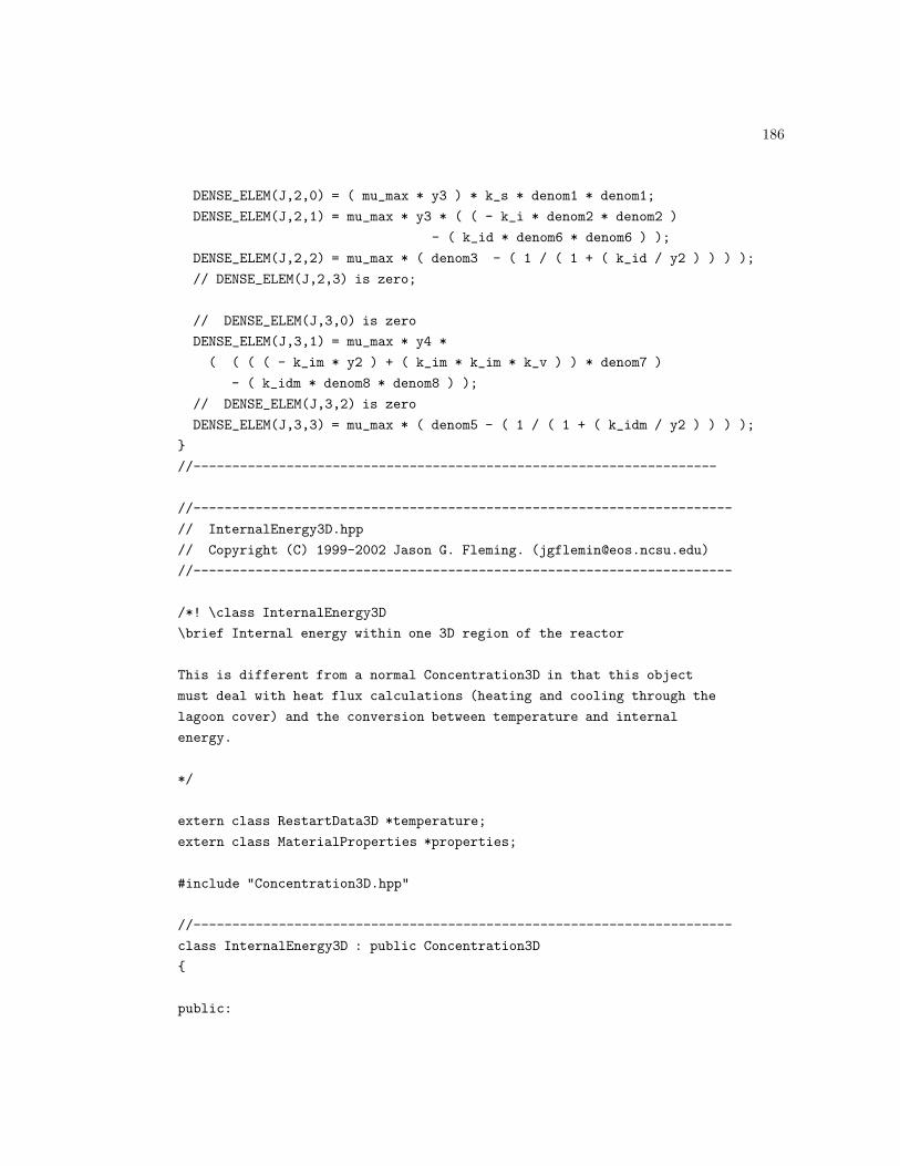
186
DENSE_ELEM(J,2,0) = ( mu_max * y3 ) * k_s * denom1 * denom1;
DENSE_ELEM(J,2,1) = mu_max * y3 * ( ( - k_i * denom2 * denom2 )
- ( k_id * denom6 * denom6 ) );
DENSE_ELEM(J,2,2) = mu_max * ( denom3 - ( 1 / ( 1 + ( k_id / y2 ) ) ) );
// DENSE_ELEM(J,2,3) is zero;
// DENSE_ELEM(J,3,0) is zero
DENSE_ELEM(J,3,1) = mu_max * y4 *
( ( ( ( - k_im * y2 ) + ( k_im * k_im * k_v ) ) * denom7 )
- ( k_idm * denom8 * denom8 ) );
// DENSE_ELEM(J,3,2) is zero
DENSE_ELEM(J,3,3) = mu_max * ( denom5 - ( 1 / ( 1 + ( k_idm / y2 ) ) ) );
}
//--------------------------------------------------------------------
//----------------------------------------------------------------------
// InternalEnergy3D.hpp
// Copyright (C) 1999-2002 Jason G. Fleming. ([email protected])
//----------------------------------------------------------------------
/*! \class InternalEnergy3D
\brief Internal energy within one 3D region of the reactor
This is different from a normal Concentration3D in that this object
must deal with heat flux calculations (heating and cooling through the
lagoon cover) and the conversion between temperature and internal
energy.
*/
extern class RestartData3D *temperature;
extern class MaterialProperties *properties;
#include "Concentration3D.hpp"
//----------------------------------------------------------------------
class InternalEnergy3D : public Concentration3D
{
public:

187
InternalEnergy3D(void);
virtual ~InternalEnergy3D(void);
//! calculate the value of internal energy, given temperature and properties
void CalculateInternalEnergyFromTemperature(RestartData3D *temperature,
MaterialProperties *properties);
//! calculates temperature from internal energy, given material properties
void CalculateTemperatureFromInternalEnergy(RestartData3D *temperature,
MaterialProperties *properties);
//! calculates new value based on heat flux and time step
virtual void ApplyHeatFlux(double inlet_temperature,
double heat_flux, int i, int j, int k,
MaterialProperties *properties,
double time_step);
//! sets up boundary conditions
virtual void Initialize(RestartData3D *temperature,
MaterialProperties *properties,
double temperature_boundary_condition);
//! calculates the effect of bubble mixing
virtual void Diffuse(MaterialProperties *properties,
DoubleData3D *this_biogas_generation,
DoubleData3D *below_biogas_generation,
RestartData3D *temperature,
double time_step);
protected:
//! temperature of the slurry flowing into the region
double temperature_boundary_condition;
};
//----------------------------------------------------------------------
//----------------------------------------------------------------------
// Filename: InternalEnergy3D.cpp
// Copyright (C) 1999-2002 Jason G. Fleming. ([email protected])

188
//----------------------------------------------------------------------
extern "C" {
#include<gnome-xml/parser.h>
#include<gnome-xml/tree.h>
#include<malloc.h>
}
#include<iostream.h>
#include<strstream.h>
#include<string.h>
#include "ls3d_Object.hpp"
#include "Geometry3D.hpp"
#include "MaterialProperties.hpp"
#include "UnsteadyInputData.hpp"
#include "TridiagonalMatrix.hpp"
#include "InternalEnergy3D.hpp"
//----------------------------------------------------------------------
InternalEnergy3D::InternalEnergy3D(void)
{
// call base class constructors
}
//----------------------------------------------------------------------
//----------------------------------------------------------------------
InternalEnergy3D::~InternalEnergy3D(void)
{
// call base class destructors
}
//----------------------------------------------------------------------
//----------------------------------------------------------------------
void InternalEnergy3D::Initialize(RestartData3D *temperature,
MaterialProperties *properties,
double temperature_boundary_condition)
{
double specific_heat;
specific_heat = properties->GetSpecificHeat();
Concentration3D::Initialize();

189
this->temperature_boundary_condition = temperature_boundary_condition;
this->inflow = specific_heat * ( 273.0 + temperature_boundary_condition );
this->CalculateInternalEnergyFromTemperature(temperature, properties);
}
//----------------------------------------------------------------------
//----------------------------------------------------------------------
void InternalEnergy3D::CalculateInternalEnergyFromTemperature
(RestartData3D *temperature,MaterialProperties *properties)
{
double specific_heat;
double internal_energy;
double t; // temperature at a particular location
int lb, rb, bb, tb, ab, pb; // domain boundaries
int i, j, k; // mesh point counters
lb = this->domain3D->GetLeftBoundary();
rb = this->domain3D->GetRightBoundary();
bb = this->domain3D->GetBottomBoundary();
tb = this->domain3D->GetTopBoundary();
ab = this->domain3D->GetAnteriorBoundary();
pb = this->domain3D->GetPosteriorBoundary();
specific_heat = properties->GetSpecificHeat();
// set all to zero (including ghostcells)
this->SetValue(0.0);
for ( i=lb ; i<=rb ; ++i ) {
for ( j=bb ; j<=tb ; ++j ) {
for ( k=ab ; k<=pb ; ++k ) {
t = temperature->GetValue(i, j, k);
internal_energy = specific_heat * ( 273.0 + t );
this->value[i][j][k] = internal_energy;
}
}
}
}
//----------------------------------------------------------------------
//----------------------------------------------------------------------

190
void InternalEnergy3D::CalculateTemperatureFromInternalEnergy
(RestartData3D *temperature, MaterialProperties *properties)
{
double specific_heat;
double t; // temperature at a particular location
int lb, rb, bb, tb, ab, pb; // domain boundaries
int i, j, k; // mesh point counters
lb = this->domain3D->GetLeftBoundary();
rb = this->domain3D->GetRightBoundary();
bb = this->domain3D->GetBottomBoundary();
tb = this->domain3D->GetTopBoundary();
ab = this->domain3D->GetAnteriorBoundary();
pb = this->domain3D->GetPosteriorBoundary();
specific_heat = properties->GetSpecificHeat();
// set all to zero (including ghostcells)
temperature->SetValue(0.0);
for ( i=lb ; i<=rb ; ++i ) {
for ( j=bb ; j<=tb ; ++j ) {
for ( k=ab ; k<=pb ; ++k ) {
t = ( this->value[i][j][k] / specific_heat ) - 273.0;
temperature->SetValue(i, j, k, t);
}
}
}
}
//----------------------------------------------------------------------
//----------------------------------------------------------------------
void InternalEnergy3D::ApplyHeatFlux(double inlet_temperature,
double heat_flux, int i, int j, int k,
MaterialProperties *properties,
double time_step)
{
double density;
double heat_transferred; // kJ
double surface_area; // area of lagoon cover for one mesh cell (m^2)
double volume; // m^3

191
double mass; // kg
double total_internal_energy; // capital U, kJ
double delta_x, delta_y, delta_z; // mesh spacing in meters
delta_x = this->domain3D->GetXMeshSpacing();
delta_y = this->domain3D->GetYMeshSpacing();
delta_z = this->domain3D->GetZMeshSpacing();
double specific_heat;
specific_heat = properties->GetSpecificHeat();
surface_area = delta_x * delta_z;
// heat flux is kW/m^2, surface area is m^2, time step is seconds
heat_transferred = heat_flux * surface_area * time_step; // kJ
// internal energy is kJ/kg
density = properties->GetDensity();
volume = delta_x * delta_y * delta_z;
mass = density * volume;
total_internal_energy = this->value[i][j][k] * mass;
total_internal_energy += heat_transferred;
this->value[i][j][k] = total_internal_energy / mass;
this->temperature_boundary_condition = inlet_temperature;
this->inflow = specific_heat * ( 273.0 + temperature_boundary_condition );
}
//----------------------------------------------------------------------
//----------------------------------------------------------------------
void InternalEnergy3D::Diffuse(MaterialProperties *properties,
DoubleData3D *this_biogas_generation,
DoubleData3D *below_biogas_generation,
RestartData3D *temperature,
double time_step)
{
// This method calculates the amount of material one slurry volume
// element that is transferred to the slurry volume elements above
// and below due to diffusion and bubble mixing effects.
int i, j, k; // mesh point counters in i, j, k directions
int lb, rb, bb, tb, ab, pb; // domain boundaries

192
int gc; // number of ghost cells
int y_cells; // number of cells in y direction
double density;
double specific_heat;
double *conductivity; // kW/mK of a particular cell
double *bubble_volume; // volume of bubbles passing through a cell
double ap0; // coefficient from Patankar
double delta_x, delta_y, delta_z; // meters, assuming 1.0m mesh spacing
double this_temperature; // deg.C, used for buoyancy calcs
double above_temperature; // deg.C, used for buoyancy calcs
double cell_volume; // volume of a mesh cell, m^3
double gas_thru; // gas throughput, l/(m^3.s)
gc = this->domain3D->GetNumOfGhostCells();
lb = this->domain3D->GetLeftBoundary();
rb = this->domain3D->GetRightBoundary();
bb = this->domain3D->GetBottomBoundary();
tb = this->domain3D->GetTopBoundary();
ab = this->domain3D->GetAnteriorBoundary();
pb = this->domain3D->GetPosteriorBoundary();
y_cells = this->domain3D->GetNumOfYCells() + ( 2 * gc );
density = properties->GetDensity();
specific_heat = properties->GetSpecificHeat();
delta_x = this->domain3D->GetXMeshSpacing();
delta_y = this->domain3D->GetYMeshSpacing();
delta_z = this->domain3D->GetZMeshSpacing();
cell_volume = delta_x * delta_y * delta_z;
ap0 = specific_heat * density * delta_y / time_step;
TridiagonalMatrix *TDMA;
// solve 1D transient heat diffusion equation in j direction
TDMA = new TridiagonalMatrix(y_cells);
conductivity = new double[y_cells];
bubble_volume = new double[y_cells];
j=bb;
for ( i=lb ; i<=rb ; ++i ) {
for ( k=ab ; k<=pb ; ++k ) {

193
// bubble volume in the vertical column of cells
bubble_volume[bb] = below_biogas_generation->GetValue(i, 2, k)
+ this_biogas_generation->GetValue(i, j, k);
for ( j=bb+1 ; j<=tb ; ++j ) {
bubble_volume[j] = bubble_volume[j-1] +
+ this_biogas_generation->GetValue(i, j, k);
}
for ( j=bb ; j<=tb ; ++j ) {
gas_thru = bubble_volume[j] / ( cell_volume * time_step ); //l/(m^3.s)
conductivity[j] = ( this->mass_diffusivity_slope * gas_thru )
+ this->diffusion_coefficient;
}
conductivity[bb-1] = 1.0e-15;
conductivity[tb+1] = 1.0e-15;
// mixing (conductivity) due to buoyancy driven flow
for ( j=bb ; j<=tb ; ++j ) {
this_temperature = temperature->GetValue(i, j, k);
above_temperature = temperature->GetValue(i, (j+1), k);
if ( this_temperature > above_temperature ) {
if ( conductivity[j] < (100000.0 * this->diffusion_coefficient) ) {
conductivity[j] = 100000.0 * this->diffusion_coefficient;
}
}
}
// bottom boundary is adiabatic
TDMA->a[bb-1] = 1.0;
TDMA->b[bb-1] = 0.0;
TDMA->c[bb-1] = 0.0;
TDMA->d[bb-1] = temperature->GetValue(i, bb, k);
TDMA->sum_of_neighbors[bb-1] = 0.0;
// interior of domain use harmonic mean for interface
// conductivity
for ( j=bb ; j<=tb ; ++j ) {
TDMA->b[j] = ( 2.0 * conductivity[j+1] * conductivity[j]
/ ( conductivity[j+1] + conductivity[j] ) ) / delta_y;
TDMA->c[j] = ( 2.0 * conductivity[j-1] * conductivity[j]

194
/ ( conductivity[j-1] + conductivity[j] ) ) / delta_y;
TDMA->a[j] = TDMA->b[j] + TDMA->c[j] + ap0;
TDMA->d[j] = ap0 * temperature->GetValue(i, j, k);
TDMA->sum_of_neighbors[j] = 0.0;
}
// top boundary is adiabatic
TDMA->a[tb+1] = 1.0;
TDMA->b[tb+1] = 0.0;
TDMA->c[tb+1] = 0.0;
TDMA->d[tb+1] = temperature->GetValue(i, tb, k);
TDMA->sum_of_neighbors[tb+1] = 0.0;
TDMA->Solve(y_cells, bb-1, tb+1);
for ( j=bb ; j<=tb ; ++j ) {
temperature->SetValue(i, j, k, TDMA->solution[j]);
if ( TDMA->solution[j] < 0 ) {
cerr << "ERROR: In Internal Energy, negative value of temperature";
cerr << this->value[i][j][k] << " detected at the \n";
cerr << "location i=" << i << " j=" << j << " k=" << k << ’\n’;
}
}
}
}
delete TDMA;
delete[] conductivity;
delete[] bubble_volume;
this->CalculateInternalEnergyFromTemperature(temperature, properties);
}
//--------------------------------------------------------------------
//----------------------------------------------------------------------
// Filename: LagoonSim3DShell.cpp
// Copyright (C) 1999-2002 Jason G. Fleming. ([email protected])
//----------------------------------------------------------------------
#include<iostream.h>
#include<qstring.h>

195
#include<hdf5.h>
#include "ls3d_Object.hpp"
#include "HillReactor3D.hpp"
#include "ShellPostProcess.hpp"
int main(int argc, char *argv[])
{
/////////////////////////////
// parse command line options
/////////////////////////////
QString fn; // name of file containing problem definition or post
// processing instructions
int option = 1; // keep track of number of options
int solve = 0; // boolean, 1 if user wants to solve a new problem
int post = 0; // boolean, 1 if user wants to post process existing data
while ( option <= argc - 1 ) {
if ( strcmp(argv[option],"--problem-definition") == 0 ) {
solve = 1; // user wants to solve a new problem
++option;
fn = argv[option];
}
if ( strcmp(argv[option],"--post-process") == 0 ) {
post = 1; // user wants to post process existing output data
++option;
fn = argv[option];
}
++option;
}
/////////////////////////////
// perform requested action
/////////////////////////////
if ( solve == 1 ) {
HillReactor3D *barham_lagoon;
barham_lagoon = new HillReactor3D(fn);
barham_lagoon->Initialize();
barham_lagoon->Solve();
delete barham_lagoon;

196
}
if ( post == 1 ) {
ShellPostProcess *post_processor;
post_processor = new ShellPostProcess(fn);
post_processor->PostProcess();
delete post_processor;
}
return(0);
}
//--------------------------------------------------------------------
// Filename: MaterialProperties.hpp
// Copyright (C) 1999-2002 Jason G. Fleming. ([email protected])
//--------------------------------------------------------------------
/*! \class MaterialProperties
\brief density, viscosity, specific heat, kinematic viscosity
*/
class MaterialProperties
{
public:
MaterialProperties(void);
~MaterialProperties(void);
void SetXMLInputNode(xmlNodePtr node) { this->xml_input_node = node; }
double GetSpecificHeat(void) { return(this->specific_heat); }
double GetDensity(void) { return(this->density); };
double GetViscosity(void) { return(this->viscosity); }
double GetKinematicViscosity(void) { return(this->kinematic_viscosity); }
void Initialize(void);

197
protected:
//! node in XML tree where input material properties data is found
xmlNodePtr xml_input_node;
//! units: kg/m3
double density;
//! units: Ns/m^2, = 0.000874 for water @300K
double viscosity;
//! units: kJ/(kg K) = 4.181 for water @300K
double specific_heat;
//! this is nu, what units?
double kinematic_viscosity;
};
//--------------------------------------------------------------------
// Filename: MaterialProperties.cpp
// Copyright (C) 1999, 2000, 2001 Jason G. Fleming. ([email protected])
//--------------------------------------------------------------------
extern "C" {
#include<gnome-xml/parser.h>
#include<gnome-xml/tree.h>
}
#include<string.h>
#include "MaterialProperties.hpp"
//--------------------------------------------------------------------
MaterialProperties::MaterialProperties(void)
{
// do something
}
//--------------------------------------------------------------------
//--------------------------------------------------------------------
MaterialProperties::~MaterialProperties(void)
{

198
// do something
}
//--------------------------------------------------------------------
//--------------------------------------------------------------------
void MaterialProperties::Initialize(void)
{
// This function loads material properties from an XML tree
xmlChar *content;
float value;
xmlNodePtr node;
node = this->xml_input_node;
for( node=node->childs; node != NULL; node=node->next ) {
content = xmlNodeGetContent(node);
sscanf((const char *)content, "%f\n", &value);
if ( !strcmp((const char *)node->name,"Density") ) {
this->density = value;
}
if ( !strcmp((const char *)node->name,"Viscosity") ) {
this->viscosity = value;
}
if ( !strcmp((const char *)node->name,"SpecificHeat") ) {
this->specific_heat = value;
}
}
this->kinematic_viscosity = this->viscosity / this->density;
}
//--------------------------------------------------------------------
//--------------------------------------------------------------------
// Filename: RestartData3D.hpp
// Copyright (C) 1999-2002 Jason G. Fleming. ([email protected])
//--------------------------------------------------------------------
/*! \class RestartData3D
\brief Data that can read itself in from a previous output file

199
*/
#ifndef RESTARTDATA3D_HPP
#define RESTARTDATA3D_HPP
#include "DoubleData3D.hpp"
//--------------------------------------------------------------------
class RestartData3D : public DoubleData3D
{
public:
RestartData3D(void);
virtual void SetXMLTag(char *tag) { this->xml_tag = tag; }
virtual void SetBoundaryCondition(double value) { this->inflow = value; }
virtual void ActivateRestart(void) { this->use_restart = 1; }
virtual void ActivateVisualization(void) { this->viz = 1; }
virtual void SetRestartIndex(int index) { this->restart_index = index; }
virtual void SetRestartFileName(char *name);
virtual void Initialize(void);
//! set name of output file to be visualized
void SetVisualizationFileName(QString fn) { this->viz_restart_fn = fn; }
protected:
//! inlet boundary condition
double inflow;
//! name of XML tag in input file
char *xml_tag;
//! name of HDF5 output file to be used for restart data

200
char restart_file_name[80];
//! name of group (frame) to get restart data from
int restart_index;
//! 1 if initial conditions should come from a restart file, 0 otherwise
int use_restart;
//! name of output velocity data for use with visualization
QString viz_restart_fn;
//! boolean, 1 if this should set up for visualization
int viz;
};
//--------------------------------------------------------------------
#endif
//--------------------------------------------------------------------
// Filename: RestartData3D.cpp
// Copyright (C) 1999-2002 Jason G. Fleming. ([email protected])
//--------------------------------------------------------------------
extern "C" {
#include<gnome-xml/parser.h>
#include<gnome-xml/tree.h>
#include "hdf5.h"
#include<malloc.h>
}
#include<iostream.h>
#include "ls3d_Object.hpp"
#include "RestartData3D.hpp"
#include "Geometry3D.hpp"
//--------------------------------------------------------------------
RestartData3D::RestartData3D(void)
{
this->viz = 0;
this->use_restart = 0;
}
//--------------------------------------------------------------------

201
//--------------------------------------------------------------------
void RestartData3D::SetRestartFileName(char *name)
{
strcpy(this->restart_file_name, name);
this->restart_file_name[sizeof(this->restart_file_name)-1] = ’\0’;
}
//--------------------------------------------------------------------
//----------------------------------------------------------------------
void RestartData3D::Initialize(void)
{
DoubleData3D::Initialize();
if ( this->use_restart == 1 || this->viz == 1 ) {
int i, j, k; // mesh point counters
hid_t scalar_dataset;
hid_t region_group;
hid_t current_frame_group;
hid_t scalar_filespace;
hid_t scalar_memspace;
hsize_t dims[3]; // size of dataset i.e., 20x20, 25x40, etc.
herr_t status;
herr_t status_n;
char this_frame_name[9];
DoubleData3D *scalar;
int rank; // dimensionality of data: 1D, 2D, or 3D
// form the frame name
sprintf(this_frame_name, "frame%04d", this->restart_index);
// open the restart file
hid_t restart_file_handle = -1;
if ( this->use_restart == 1 ) {
restart_file_handle =
H5Fopen(this->restart_file_name, H5F_ACC_RDWR, H5P_DEFAULT);
}
if ( this->viz == 1 ) {
// cerr << "Opening " << this->viz_restart_fn << "...\n";

202
restart_file_handle = H5Fopen(this->viz_restart_fn, H5F_ACC_RDONLY,
H5P_DEFAULT);
}
// open the Reactor3D group
hid_t reactor3D_group;
reactor3D_group = H5Gopen(restart_file_handle, "Reactor3D");
// open the region group
region_group = H5Gopen(reactor3D_group, this->region_name);
// open the group for the restart frame
current_frame_group = H5Gopen(region_group, this_frame_name);
// cerr << "Opening " << this_frame_name << "...\n";
scalar_dataset = H5Dopen(current_frame_group, this->name);
scalar_filespace = H5Dget_space(scalar_dataset);
rank = H5Sget_simple_extent_ndims(scalar_filespace);
status_n = H5Sget_simple_extent_dims(scalar_filespace, dims, NULL);
// Allocate memory
scalar = new DoubleData3D;
scalar->SetDimensions((int)dims[0], (int)dims[1], (int)dims[2]);
scalar->Initialize();
// define the memory space to read dataset
scalar_memspace = H5Screate_simple(rank, dims, NULL);
// read dataset back
status = H5Dread(scalar_dataset, H5T_NATIVE_DOUBLE, scalar_memspace,
scalar_filespace, H5P_DEFAULT, scalar->GetPointer());
int lb, bb, ab;
lb = this->domain3D->GetLeftBoundary();
bb = this->domain3D->GetBottomBoundary();
ab = this->domain3D->GetAnteriorBoundary();
for ( k=0; k<= (int) dims[2]-1; ++k ) {
for ( j=0; j<= (int) dims[1]-1; ++j ) {
for ( i=0; i<= (int) dims[0]-1; ++i ) {

203
this->value[i+lb][j+bb][k+ab] = scalar->GetValue(i, j, k);
}
}
}
delete scalar;
H5Dclose(scalar_dataset);
H5Sclose(scalar_filespace);
H5Sclose(scalar_memspace);
H5Gclose(current_frame_group);
H5Gclose(region_group);
H5Gclose(reactor3D_group);
H5Fclose(restart_file_handle);
}
}
//----------------------------------------------------------------------
//--------------------------------------------------------------------
// Filename: TridiagonalMatrix.hpp
// Copyright (C) 1999-2002 Jason G. Fleming. ([email protected])
//--------------------------------------------------------------------
/*! \class TridiagonalMatrix
\brief Used for solving 3D diffusion equations in a 1D line-by-line method
This class holds the data for a Tridiagonal matrix, as well as methods
for populating the matrix entries, solving, and getting the solution
back. The solution of tridiagonal matrices is described in many texts
on numerocal methods. The variable names were chosen to match the
description used in Patankar’s Numerical Heat Transfer and Fluid Flow
book. The class also contains a data member (sum_of_neighbors) that is
only useful when solving a 3D problem in a 1D line-by-line
method. General TDMA algorithms don’t use this variable; read Patankar
for more details on this.
*/
class TridiagonalMatrix
{
public:
//! Constructor, allocates memory based on value of length (number of rows).
/*! Allocates memory for eight vectors: a, b, c, d, P, Q,

204
sum_of_neighbors, and solution. These letters are selected to match
those used in Patankar’s description of the TriDiagonal Matrix
Algorithm in Numerical Heat Transfer and Fluid Flow. This object is
typically constructed once and used to solve many matrices before
destruction. */
TridiagonalMatrix(int length);
//! Destructor. Frees memory used by eight vectors.
~TridiagonalMatrix(void);
//! left hand side coefficient; see Patankar
double *a;
//! i+1 coefficient; see Patankar
double *b;
//! i-1 coefficient; see Patankar
double *c;
//! right hand side ; see Patankar
double *d;
//! Sum of the neighboring nodes in other coordinate directions.
/*! This is due to the inherent one-dimensionality in the
tridiagonal matrix algorithm. This only comes into play when using
the TDMA to solve a 3D problem in a 1D line-by-line method The
summation of the contribution of the neighboring nodes (in the
currently-inactive coordinate directions) is included with this
variable (see Patankar for more info). */
double *sum_of_neighbors;
//! vector containing the solution
double *solution;
//! shorthand variable used in Patankar’s description; P1 = b1 / a1
double *P;
//! shorthand variable used in Patankar’s description; Q1 = d1 / a1
double *Q;

205
//! Solves the tridiagonal matrix.
/*!
\param length total number of rows in the matrix, including ghostpoints.
\param begin index value corresponding to the first real
(non-ghostpoint) row.
\param end index value corresponding to the last real row.
\return The solution is contained in the solution member of this object.
*/
void Solve(int length, int begin, int end);
};
//--------------------------------------------------------------------
// Filename: TridiagonalMatrix.cpp
// Copyright (C) 1999, 2000, 2001 Jason G. Fleming. ([email protected])
//--------------------------------------------------------------------
#include<iostream.h>
#include "TridiagonalMatrix.hpp"
//--------------------------------------------------------------------
TridiagonalMatrix::TridiagonalMatrix(int length)
{
a = new double[length];
b = new double[length];
c = new double[length];
d = new double[length];
sum_of_neighbors = new double[length];
solution = new double[length];
P = new double[length];
Q = new double[length];
}
//--------------------------------------------------------------------
//--------------------------------------------------------------------
TridiagonalMatrix::~TridiagonalMatrix(void)
{
delete[] a;
delete[] b;
delete[] c;
delete[] d;

206
delete[] sum_of_neighbors;
delete[] solution;
delete[] P;
delete[] Q;
}
//--------------------------------------------------------------------
//--------------------------------------------------------------------
void TridiagonalMatrix::Solve(int length, int begin, int end)
{
//! equation counter, could represent x, y, or z mesh pts
int index;
//! used to avoid division by zero
double denominator;
//! down ...
//! boundary
P[begin] = b[begin];
//! boundary
Q[begin] = d[begin];
denominator = a[begin];
if ( denominator == 0.0 ) {
//! avoid division by zero
P[begin] = 0.0;
Q[begin] = 0.0;
} else {
P[begin] /= denominator;
Q[begin] /= denominator;
}
for ( index=begin+1 ; index<=end ; ++index ) {
denominator = a[index] - c[index] * P[index-1];
P[index] = b[index] ;
Q[index] = d[index] + c[index] * Q[index-1];
if ( denominator != 0.0 ) {
P[index] /= denominator;
Q[index] /= denominator;
} else {
P[index] = 0.0; // avoid division by zero

207
Q[index] = 0.0; // avoid division by zero
}
}
//! boundary
solution[end] = Q[end] + sum_of_neighbors[end];
for ( index=end-1 ; index>=begin ; --index ) {
solution[index] = P[index] * solution[index+1] + Q[index]
+ sum_of_neighbors[index];
}
}
//--------------------------------------------------------------------
//--------------------------------------------------------------------
// Filename: UnsteadyInputData.hpp
//--------------------------------------------------------------------
#ifndef UNSTEADYINPUTDATA_HPP
#define UNSTEADYINPUTDATA_HPP
/*! \class UnsteadyInputData
\brief Used for managing time series data used as input.
This class manages data (from ASCII files) that will somehow be used
as input to the simulation. The class expects one number per line with
nothing else on the line. No inherent expectation of any units on the
input numbers (up to the user/developer to make sure the units are
right). Also no time stamps allowed in the file, user specifies the
time difference between data (in seconds) in the input .xml file. */
class UnsteadyInputData : public ls3d_Object
{
public:
UnsteadyInputData(void);
virtual ~UnsteadyInputData(void);

208
virtual void SetIndex(int index)
{ this->current_index = index; }
virtual void SetNumberOfMeasurements(int number_of_measurements)
{ this->num_of_measurements = number_of_measurements; }
virtual void SetTimeInterval(double interval)
{ this->time_between_measurements = interval; }
virtual double GetTimeInterval(void)
{ return(this->time_between_measurements); }
virtual double GetValue(void) { return(value[current_index]); }
//! set name of ASCII input file
virtual void SetInputDataFileName(char *name);
virtual void IncrementTime(double time_step);
virtual double GetTimeUntilNextMeasurement(void);
virtual void Initialize(void);
virtual void Output(void);
protected:
//! name of ASCII text file with input data
/*! This file should contain one datum per line with
nothing else on the line */
char *input_data_file_name;
//! array, units depend on application
double *value;
//! output number (used for extending output dataset size)
int output_number;
//! number of data in the file
int num_of_measurements;

209
//! seconds
float time_between_measurements;
//! seconds
float time_since_last_update;
//! array index
int current_index;
};
#endif
//--------------------------------------------------------------------
// Filename: UnsteadyInputData.cpp
// Copyright (C) 1999-2002 Jason G. Fleming. ([email protected])
//--------------------------------------------------------------------
extern "C" {
#include<gnome-xml/parser.h>
#include<gnome-xml/tree.h>
#include<string.h>
#include<stdlib.h>
#include "hdf5.h"
}
#include<iostream.h>
#include<strstream.h>
#include<fstream.h>
#include "ls3d_Object.hpp"
#include "UnsteadyInputData.hpp"
//---------------------------------------------------------------------
UnsteadyInputData::UnsteadyInputData( void )
{
this->time_since_last_update = 0.0;
this->current_index = 0;
this->output_number = 0;
}
//---------------------------------------------------------------------

210
//---------------------------------------------------------------------
UnsteadyInputData::~UnsteadyInputData(void)
{
delete[] this->value;
}
//---------------------------------------------------------------------
//---------------------------------------------------------------------
void UnsteadyInputData::SetInputDataFileName(char *name)
{
int length;
length = strlen(name);
this->input_data_file_name = new char[length+1];
strcpy(this->input_data_file_name, name);
}
//---------------------------------------------------------------------
//---------------------------------------------------------------------
void UnsteadyInputData::Initialize(void)
{
// This function gets the time series of data from an ascii file and
// puts it into an array. It expects to find just one floating point
// number per line with nothing else on the line.
int i; // data point counter
ifstream data_file;
// a value of -99 in the data file represents a gap in the measured
// data ... in this case we set the value to be the same as the one
// from the previous hour or zero if the first hour is missing
// allocate memory
this->value = new double[this->num_of_measurements];
// open file
data_file.open(this->input_data_file_name);
i = 0;
if ( data_file.bad() ) {
cerr << "ERROR: Could not open " << this->input_data_file_name << ’\n’;

211
} else {
cerr << "Loading " << this->input_data_file_name << " ...\n";
}
while ( i < num_of_measurements ) {
data_file >> this->value[i];
if ( this->value[i] == -99 ) {
if ( i == 0 ) {
this->value[i] = 0;
} else {
this->value[i] = this->value[i-1];
}
}
++i;
}
cerr << "... " << this->input_data_file_name << " completely loaded.\n";
}
//---------------------------------------------------------------------
//---------------------------------------------------------------------
void UnsteadyInputData::IncrementTime(double time_step)
{
this->time_since_last_update += time_step;
// determine if it is time to update the slurry temperature
if ( this->time_since_last_update >= this->time_between_measurements ) {
this->time_since_last_update = 0.0;
++(this->current_index);
}
}
//---------------------------------------------------------------------
//---------------------------------------------------------------------
double UnsteadyInputData::GetTimeUntilNextMeasurement(void)
{
double remaining_time;
remaining_time = this->time_between_measurements
- this->time_since_last_update;
return(remaining_time);
}

212
//---------------------------------------------------------------------
//---------------------------------------------------------------------
void UnsteadyInputData::Output(void)
{
// check to see if the dataset has already been created in the
// output file. if not, create it. if so, extend it and add the
// new value
// place temperature data in output file
// open (or create) the output file
hid_t output_file_handle;
output_file_handle =
H5Fopen(this->output_file_name, H5F_ACC_RDWR, H5P_DEFAULT);
if ( output_file_handle < 0 ) {
output_file_handle = H5Fcreate(this->output_file_name, H5F_ACC_TRUNC,
H5P_DEFAULT, H5P_DEFAULT);
}
hid_t dataset; // handle for data
hid_t dataspace; // handle
hid_t plist; // property list for the data set
herr_t status;
hid_t datatype; // handle
hsize_t dims[1] = { 1 };
hsize_t max_dims[1] = { H5S_UNLIMITED };
datatype = H5Tcopy(H5T_NATIVE_DOUBLE);
status = H5Tset_order(datatype, H5T_ORDER_LE);
dataset = H5Dopen(output_file_handle, this->name);
plist = H5Pcreate(H5P_DATASET_CREATE);
if ( dataset < 0 ) {
dataspace = H5Screate_simple(1, dims, max_dims);
dataset
= H5Dcreate(output_file_handle, this->name, datatype,
dataspace, plist);
status = H5Dwrite(dataset, H5T_NATIVE_DOUBLE, H5S_ALL, H5S_ALL,

213
H5P_DEFAULT, &this->value);
} else {
hid_t filespace; // for selecting the hyperslab to insert data
hssize_t offset[1]; // location of value to be added to dataset
hsize_t size[1]; // location of value to be added to dataset
size[0] = this->output_number + 1;
offset[0] = this->output_number;
dims[0] = 1;
dataspace = H5Screate_simple(1, dims, max_dims);
status = H5Dextend(dataset, size);
// select hyperslab
filespace = H5Dget_space(dataset);
status = H5Sselect_hyperslab(filespace, H5S_SELECT_SET, offset, NULL,
dims, NULL);
// write the data to the dataset using default transfer properties
status = H5Dwrite(dataset, H5T_NATIVE_DOUBLE, dataspace, filespace,
H5P_DEFAULT, &this->value);
H5Sclose(filespace);
}
// close and release resources
H5Dclose(dataset);
H5Pclose(plist);
H5Tclose(datatype);
H5Sclose(dataspace);
H5Fclose(output_file_handle);
}
//---------------------------------------------------------------------
//--------------------------------------------------------------------
// Velocity.hpp Executive Summary:
// Copyright (C) 1999-2002 Jason G. Fleming.
//--------------------------------------------------------------------

214
/*! \class Velocity
\brief All the data elements in one cell of a Velocity3D object
*/
#ifndef VELOCITY3D_HPP
#define VELOCITY3D_HPP
extern class TridiagonalMatrix *TDMA;
extern class Geometry3D *domain3D;
extern class MaterialProperties *properties;
#include "DoubleData3D.hpp"
#include<qstring.h>
//--------------------------------------------------------------------
class Velocity
{
public:
//! velocity in x direction (cell center), m/s
double u;
//! velocity in y direction (cell center), m/s
double v;
//! velocity in y direction (cell center), m/s
double w;
//! left face u velocity, m/s
double left;
//! right face u velocity, m/s
double right;
//! bottom face v velocity, m/s
double bottom;
//! top face v velocity, m/s
double top;

215
//! front face w velocity, m/s
double anterior;
//! back face w velocity, m/s
double posterior;
//! east face u velocity
double u_e;
//! north face v velocity
double v_n;
//! front face w velocity
double w_t;
//! guessed pressure field (p* in Patankar)
double p_star;
//! corrected pressure field (p’ in Patankar)
double p_corr;
//! pressure field (p in Patankar)
double p;
//! guessed x direction velocity
double u_star;
//! guessed y direction velocity
double v_star;
//! guessed z direction velocity
double w_star;
//! x-dir momentum convection/diffusion coefficient (east)
double a_e;
//! x-dir momentum convection/diffusion coefficient (west)
double a_w;
//! y-dir momentum convection/diffusion coefficient (north)
double a_n;

216
//! y-dir momentum convection/diffusion coefficient (south)
double a_s;
//! z-dir momentum convection/diffusion coefficient (top)
double a_t;
//! z-dir momentum convection/diffusion coefficient (bottom)
double a_b;
double a_Pi;
double a_Ei;
double a_Ni;
double a_Si;
double a_Ti;
double a_Bi;
double a_Pj;
double a_Ej;
double a_Wj;
double a_Nj;
double a_Tj;
double a_Bj;
double a_Pk;
double a_Ek;
double a_Wk;
double a_Nk;
double a_Sk;
double a_Tk;
double a_E;
double a_W;
double a_N;
double a_S;
double a_T;
double a_B;
double a_P;
double b_term;
};
//--------------------------------------------------------------------
/*! \class Velocity3D
\brief Define, solve, save, and reload velocity solutions
*/

217
//--------------------------------------------------------------------
class Velocity3D : public ls3d_Object
{
public:
Velocity3D(void);
virtual ~Velocity3D(void);
void SetGeometry(Geometry3D *domain3D)
{ this->domain3D = domain3D; }
void SetMaterialProperties(MaterialProperties *properties)
{ this->properties = properties; }
void SetPressureUnderrelaxationFactor(double factor)
{ this->pressure_underrelax = factor; }
void SetPressureCorrectionTolerance(double tolerance)
{ this->pressure_correction_tolerance = tolerance; }
void SetRestartFileName(char *name)
{ this->restart_file_name = name; this->use_restart = 1; }
void SetVisualizationRestartFileName(QString fn)
{ this->viz_restart_fn = fn; this->use_restart = 1; }
void ActivateSolver(void)
{ this->use_solver = 1; }
void ActivateOutput(void)
{ this->use_output = 1; }
void SetCourantNumber(double number)
{ this->courant_number = number; }
void SetInletXLocation(int index) { this->inlet_x_location = index; };
void SetInletYLocation(int index) { this->inlet_y_location = index; };
void SetOutletXLocation(int index) { this->outlet_x_location = index; };

218
void SetOutletYLocation(int index) { this->outlet_y_location = index; };
int GetInletXLocation(void) { return(this->inlet_x_location); };
int GetInletYLocation(void) { return(this->inlet_y_location); };
int GetOutletXLocation(void) { return(this->outlet_x_location); };
int GetOutletYLocation(void) { return(this->outlet_y_location); };
double GetLeftVelocity(int i, int j, int k);
double GetBottomVelocity(int i, int j, int k);
double GetAnteriorVelocity(int i, int j, int k);
void SetInletVolumetricFlowRate(double volumetric_flow_rate)
{ this->inlet_volumetric_flow_rate = volumetric_flow_rate; }
double GetInletVelocity(void)
{ return( (this->inlet_velocity * this->inlet_velocity_multiplier) ); }
void Initialize(void);
void Solve(void);
void Output(void);
double GetMaximumAdvectionTimeStep(void);
double GetUVelocity(int i, int j, int k);
double GetVVelocity(int i, int j, int k);
double GetWVelocity(int i, int j, int k);
protected:
void ConserveMemory(void);
void ApplyUniformZeroPressure(void);
void SolveMomentum(void);
void CalculateMomentumCoefficients(void);

219
int SolvePressureCorrection(void);
/*! This function sets the boundary conditions on the coefficients
for the pressure correction equation. */
void SetPressureCorrectionCoefficients(double density);
void SetPressureCorrectionBoundaryConditions(double bc, double density);
//! Determines local error.
/*! This function determines which cell face velocity is the largest,
then compares the mass source term (b_term) with it.
\return mass source term which is largest relative to the local cell
face velocities.
*/
double FindRelativeMaximumSourceTerm(void);
void CopyTemporaryIntoCorrectedPressure(DoubleData3D *p_temp);
void SetUpPressureCorrectionISweep(TridiagonalMatrix *TDMA, int j, int k);
void SetUpPressureCorrectionJSweep(TridiagonalMatrix *TDMA, int i, int k);
void SetUpPressureCorrectionKSweep(TridiagonalMatrix *TDMA, int i, int j);
void CalculateCorrectedPressure(void);
void CalculateCorrectedVelocity(void);
void UseCorrectedPressureAsGuessed(void);
//! Calculates cell centered velocity based on cell face velocity.
/*! This function takes the one sided face velocities calculated by
the SIMPLE algoritm and turns them into a form that is usable in
the advection algorithm. It also generates cell centered velocities
for use in visualization. */
void TranslateFaceVelocity(void);
//! Sets the velocities on each side of a cell face to be equal.
/* Conservation of mass requires the velocities on each side of a

220
cell face to be equal. This function also sets up the velocity
boundary conditions required to get advection working properly. */
void CompleteConsistentFaceVelocity(void);
//! Check velocities to ensure that they are mass conservative
void ConservationCheck(void);
//! reads cell centered velocities from an HDF formatted restart file
void LoadVelocityFromRestart(void);
void ApplyBarhamLagoonFluidIC(void);
Geometry3D *domain3D;
Velocity ***vel0D;
DoubleData3D *U_velocity;
DoubleData3D *V_velocity;
DoubleData3D *W_velocity;
DoubleData3D *Ue_velocity;
DoubleData3D *Vn_velocity;
DoubleData3D *Wt_velocity;
int inlet_x_location;
int inlet_y_location;
int outlet_x_location;
int outlet_y_location;
MaterialProperties *properties;
//! make it possible to turn the velocity on/off (0=off, 1=on)
int use_velocity;
//! whether or not to save the velocity solution in output file
// (0=no, 1=yes)
int save_velocity;
//! Maximum change in solution for convergence.
/*! Number which dictates how small the solution change should be

221
from iteration to iteration on the Poisson problem for the pressure
correction for us to consider the problem solved. */
double pressure_correction_tolerance;
//! Sucessive overrelaxation (SOR) parameter.
/*! This slows and stabilizes the convergence of the Poisson
problem. */
double vel_underrelax;
double pressure_underrelax;
//! allowable deviation from discrete incompressibility
double divergence;
//! velocity at inlet (units: m/s)
double inlet_velocity;
//! velocity at inlet (units: liters/s)
double inlet_volumetric_flow_rate;
//! courant = c dt / dx (unitless), must be less than 1.0 for stability
double courant_number;
//! velocity multiplier.
/*! all velocities are multiplied by this after simulation is run to
obtain a velocity field of the desired magnitude */
double inlet_velocity_multiplier;
//! name of velocity restart file
char *restart_file_name;
//! 1 if the velocity solution is needed, 0 otherwise
int use_solver;
//! 1 if the velocity solution should be saved in output file, 0 otherwise
int use_output;
//! 1 if the velocity solution should be loaded from output file, 0
// otherwise
int use_restart;
//! name of output velocity data for use with visualization

222
QString viz_restart_fn;
};
//--------------------------------------------------------------------
#endif
//--------------------------------------------------------------------
// File name: Velocity.cpp
// Copyright (C) 1999, 2000, 2001 Jason G. Fleming.
//--------------------------------------------------------------------
extern "C" {
#include<malloc.h>
#include<gnome-xml/parser.h>
#include<gnome-xml/tree.h>
#include "hdf5.h"
#include<math.h>
}
#include "ls3d_Object.hpp"
#include "Velocity.hpp"
#include "Geometry3D.hpp"
#include "TridiagonalMatrix.hpp"
#include "MaterialProperties.hpp"
#include "DoubleData3D.hpp"
//--------------------------------------------------------------------
Velocity3D::Velocity3D(void)
{
vel_underrelax = 1.0;
}
//--------------------------------------------------------------------
//--------------------------------------------------------------------
Velocity3D::~Velocity3D(void)
{
delete this->U_velocity;
delete this->V_velocity;
delete this->W_velocity;
delete this->Ue_velocity;
delete this->Vn_velocity;

223
delete this->Wt_velocity;
}
//--------------------------------------------------------------------
//--------------------------------------------------------------------
void Velocity3D::Initialize(void)
{
int i, j;
int nrows;
int ncolumns;
int ndepth;
nrows = domain3D->GetNumOfXCells() + 2 * domain3D->GetNumOfGhostCells();
ncolumns = domain3D->GetNumOfYCells() + 2 * domain3D->GetNumOfGhostCells();
ndepth = domain3D->GetNumOfZCells() + 2 * domain3D->GetNumOfGhostCells();
/* allocate pointers to pointers to rows */
this->vel0D = (Velocity ***) malloc( nrows * sizeof(Velocity **) );
this->vel0D[0] = (Velocity **)
malloc( nrows * ncolumns * sizeof(Velocity *) );
this->vel0D[0][0] = (Velocity *)
malloc( nrows*ncolumns*ndepth * sizeof(Velocity) );
for ( j=1; j<=ncolumns-1; ++j ) {
this->vel0D[0][j] = this->vel0D[0][j-1] + ndepth;
}
for ( i=1; i<=nrows-1; ++i ) {
this->vel0D[i] = this->vel0D[i-1] + ncolumns;
this->vel0D[i][0] = this->vel0D[i-1][0] + (ncolumns * ndepth);
for ( j=1; j<=ncolumns-1; j++ ) {
this->vel0D[i][j] = this->vel0D[i][j-1] + ndepth;
}
}
if ( this->use_restart == 1 ) {
this->LoadVelocityFromRestart();
this->inlet_volumetric_flow_rate = 1.8;
} else {
this->ApplyBarhamLagoonFluidIC();

224
}
// The inlet velocity boundary condition is calculated assuming that
// the inlet flow comes through a single mesh cell
double delta_x, delta_y;
double vol_inlet_flow_m3; // cubic meters per second
double inlet_area; // m^2
delta_x = this->domain3D->GetXMeshSpacing();
delta_y = this->domain3D->GetYMeshSpacing();
vol_inlet_flow_m3 = this->inlet_volumetric_flow_rate / 1000.0;
inlet_area = delta_x * delta_y;
this->inlet_velocity = vol_inlet_flow_m3 / inlet_area;
this->inlet_velocity_multiplier = 1000.0;
this->inlet_velocity /= this->inlet_velocity_multiplier;
}
//--------------------------------------------------------------------
//--------------------------------------------------------------------
void Velocity3D::Solve(void)
{
if ( this->use_solver == 1 ) {
int iteration;
/*! significant_pressure_correction is 1 if the mass source term
(b_term) in the pressure correction equation is sufficiently large
(indicating lack of convergence), 0 otherwise (0 indicates
convergence) */
int significant_pressure_correction;
iteration = 0;
significant_pressure_correction = 1;
//! Step 1: Guess the pressure field
this->ApplyUniformZeroPressure();
while( significant_pressure_correction ) {
//! Step 2: Solve momentum equations for u*, v*, and w*

225
this->SolveMomentum();
//! Step 3: Solve the p’ equation
significant_pressure_correction = this->SolvePressureCorrection();
//! Step 4: Calculate p from p = p* + p’
this->CalculateCorrectedPressure();
//! Step 5: Calculate u, v, and w using velocity correction equations
this->CalculateCorrectedVelocity();
//! Step 6: Solve for other phi’s if they influence the flow field
//! return to step 2
this->UseCorrectedPressureAsGuessed();
cerr << " iteration " << iteration << " \n";
++iteration;
if ( iteration > 100000 ) {
break;
}
}
this->TranslateFaceVelocity();
this->CompleteConsistentFaceVelocity();
this->ConservationCheck();
}
this->ConserveMemory();
}
//--------------------------------------------------------------------
//--------------------------------------------------------------------
void Velocity3D::ApplyUniformZeroPressure(void)
{
//! mesh point counters in x, y, z directions
int i, j, k;
int gc; // number of ghost cells
gc = this->domain3D->GetNumOfGhostCells();
int lb, rb, bb, tb, ab, pb; // domain boundaries
lb = this->domain3D->GetLeftBoundary();
rb = this->domain3D->GetRightBoundary();
bb = this->domain3D->GetBottomBoundary();

226
tb = this->domain3D->GetTopBoundary();
ab = this->domain3D->GetAnteriorBoundary();
pb = this->domain3D->GetPosteriorBoundary();
double bc;
bc = this->inlet_velocity; // m/s
for (i=(lb - gc); i<=(rb + gc); ++i) {
for ( j=(bb - gc); j<=(tb + gc); ++j) {
for ( k=(ab - gc); k<=(pb + gc); ++k) {
this->vel0D[i][j][k].p_star = 0.0;
this->vel0D[i][j][k].p_corr = 0.0;
this->vel0D[i][j][k].u_e = 0.0;
this->vel0D[i][j][k].v_n = 0.0;
this->vel0D[i][j][k].w_t = 0.0;
this->vel0D[i][j][k].u_star = 0.0;
this->vel0D[i][j][k].v_star = 0.0;
this->vel0D[i][j][k].w_star = 0.0;
}
}
}
this->vel0D[lb+2][bb+2][pb].w_star = bc;
this->vel0D[rb-2][tb-2][ab-1].w_star = bc;
}
//--------------------------------------------------------------------
//--------------------------------------------------------------------
void Velocity3D::SolveMomentum(void)
{
TridiagonalMatrix *TDMA;
double bc;
//! used to avoid division by zero
double denominator;
//! mesh point counters in x, y, and z directions
int i, j, k;
int gc; // number of ghost cells
gc = this->domain3D->GetNumOfGhostCells();

227
int lb, rb, bb, tb, ab, pb; // domain boundaries
lb = this->domain3D->GetLeftBoundary();
rb = this->domain3D->GetRightBoundary();
bb = this->domain3D->GetBottomBoundary();
tb = this->domain3D->GetTopBoundary();
ab = this->domain3D->GetAnteriorBoundary();
pb = this->domain3D->GetPosteriorBoundary();
//! total in each direction: domain + 2 * ghost
int x_cells, y_cells, z_cells;
x_cells = this->domain3D->GetNumOfXCells() + 2 * gc;
y_cells = this->domain3D->GetNumOfYCells() + 2 * gc;
z_cells = this->domain3D->GetNumOfZCells() + 2 * gc;
double delta_x, delta_y, delta_z; // mesh spacing in meters
delta_x = this->domain3D->GetXMeshSpacing();
delta_y = this->domain3D->GetYMeshSpacing();
delta_z = this->domain3D->GetZMeshSpacing();
//! boundary conditions
bc = this->inlet_velocity;
this->vel0D[lb+2][bb+2][pb].w_star = bc;
this->vel0D[rb-2][tb-2][ab-1].w_star = bc;
//! calculate new convection/diffusion coefficients for momentum
this->CalculateMomentumCoefficients();
// :::::::::::::::::::::::::::::::::::::::::::::::
// X M O M E N T U M
// :::::::::::::::::::::::::::::::::::::::::::::::
//! sweep in i direction
TDMA = new TridiagonalMatrix(x_cells);
for ( j=bb ; j<=tb ; ++j ) {
for ( k=ab ; k<=pb ; ++k ) {
for ( i=lb ; i<=rb ; ++i ) {
//! x momentum, i sweep
TDMA->a[i] = this->vel0D[i][j][k].a_e;
TDMA->b[i] = this->vel0D[i][j][k].a_Ei;
TDMA->c[i] = this->vel0D[i][j][k].a_Pi;

228
TDMA->d[i] = delta_y * delta_z * ( this->vel0D[i][j][k].p_star
- this->vel0D[i+1][j][k].p_star );
if ( i == rb ) { TDMA->d[i] = 0.0; }
TDMA->sum_of_neighbors[i]
= ( this->vel0D[i][j][k].a_Ni * this->vel0D[i][j+1][k].u_star
+ this->vel0D[i][j][k].a_Si * this->vel0D[i][j-1][k].u_star
+ this->vel0D[i][j][k].a_Ti * this->vel0D[i][j][k+1].u_star
+ this->vel0D[i][j][k].a_Bi * this->vel0D[i][j][k-1].u_star );
denominator = this->vel0D[i][j][k].a_e;
if ( denominator != 0.0 ) {
TDMA->sum_of_neighbors[i] /= denominator;
} else {
TDMA->sum_of_neighbors[i] = 0.0;
}
}
TDMA->Solve(x_cells, lb, rb);
for ( i=lb ; i<=rb ; ++i ) {
this->vel0D[i][j][k].u_star = TDMA->solution[i];
//! boundary values are known!
this->vel0D[rb][j][k].u_star = 0.0;
}
}
}
delete TDMA;
//! sweep in j direction
TDMA = new TridiagonalMatrix(y_cells);
for ( i=lb ; i<=rb ; ++i ) {
for ( k=ab ; k<=pb ; ++k ) {
//! x momentum, j sweep
for ( j=bb ; j<=tb ; ++j ) {
TDMA->a[j] = this->vel0D[i][j][k].a_e;
TDMA->b[j] = this->vel0D[i][j][k].a_Ni;
TDMA->c[j] = this->vel0D[i][j][k].a_Si;
TDMA->d[j] = delta_y * delta_z * ( this->vel0D[i][j][k].p_star
- this->vel0D[i+1][j][k].p_star );
if ( i == rb ) { TDMA->d[j] = 0.0; }
TDMA->sum_of_neighbors[j]
= ( this->vel0D[i][j][k].a_Ei * this->vel0D[i+1][j][k].u_star

229
+ this->vel0D[i][j][k].a_Pi * this->vel0D[i-1][j][k].u_star
+ this->vel0D[i][j][k].a_Ti * this->vel0D[i][j][k+1].u_star
+ this->vel0D[i][j][k].a_Bi * this->vel0D[i][j][k-1].u_star );
denominator = this->vel0D[i][j][k].a_e;
if ( denominator != 0.0 ) {
TDMA->sum_of_neighbors[j] /= denominator;
} else {
TDMA->sum_of_neighbors[j] = 0.0;
}
}
TDMA->Solve(y_cells, bb, tb);
for ( j=bb ; j<=tb ; ++j ) {
this->vel0D[i][j][k].u_star = TDMA->solution[j];
//! boundary values are known!
this->vel0D[rb][j][k].u_star = 0.0;
}
}
}
delete TDMA;
//! sweep in k direction
TDMA = new TridiagonalMatrix(z_cells);
for ( i=lb ; i<=rb ; ++i ) {
for ( j=bb ; j<=tb ; ++j ) {
//! x momentum, k_sweep
for ( k=ab ; k<=pb ; ++k ) {
TDMA->a[k] = this->vel0D[i][j][k].a_e;
TDMA->b[k] = this->vel0D[i][j][k].a_Ti;
TDMA->c[k] = this->vel0D[i][j][k].a_Bi;
TDMA->d[k] = delta_y * delta_z * ( this->vel0D[i][j][k].p_star
- this->vel0D[i+1][j][k].p_star );
if ( i == rb ) { TDMA->d[k] = 0.0; }
TDMA->sum_of_neighbors[k]
= ( this->vel0D[i][j][k].a_Ei * this->vel0D[i+1][j][k].u_star
+ this->vel0D[i][j][k].a_Pi * this->vel0D[i-1][j][k].u_star
+ this->vel0D[i][j][k].a_Ni * this->vel0D[i][j+1][k].u_star
+ this->vel0D[i][j][k].a_Si * this->vel0D[i][j-1][k].u_star );
denominator = this->vel0D[i][j][k].a_e;
if ( denominator != 0.0 ) {

230
TDMA->sum_of_neighbors[k] /= denominator;
} else {
TDMA->sum_of_neighbors[k] = 0.0;
}
}
TDMA->Solve(z_cells, ab, pb);
for ( k=ab ; k<=pb ; ++k ) {
this->vel0D[i][j][k].u_star = TDMA->solution[k];
//! boundary values are known!
this->vel0D[rb][j][k].u_star = 0.0;
}
}
}
delete TDMA;
// :::::::::::::::::::::::::::::::::::::::::::::::
// Y M O M E N T U M
// :::::::::::::::::::::::::::::::::::::::::::::::
//! sweep in i direction
TDMA = new TridiagonalMatrix(x_cells);
for ( j=bb ; j<=tb ; ++j ) {
for ( k=ab ; k<=pb ; ++k ) {
for ( i=lb ; i<=rb ; ++i ) {
//! y momentum, i sweep
TDMA->a[i] = this->vel0D[i][j][k].a_n;
TDMA->b[i] = this->vel0D[i][j][k].a_Ej;
TDMA->c[i] = this->vel0D[i][j][k].a_Wj;
TDMA->d[i] = delta_z * delta_x * ( this->vel0D[i][j][k].p_star
- this->vel0D[i][j+1][k].p_star );
if ( j == tb ) { TDMA->d[j] = 0.0; }
TDMA->sum_of_neighbors[i] =
( this->vel0D[i][j][k].a_Nj * this->vel0D[i][j+1][k].v_star
+ this->vel0D[i][j][k].a_Pj * this->vel0D[i][j-1][k].v_star
+ this->vel0D[i][j][k].a_Tj * this->vel0D[i][j][k+1].v_star
+ this->vel0D[i][j][k].a_Bj * this->vel0D[i][j][k-1].v_star );
denominator = this->vel0D[i][j][k].a_n;
if ( denominator != 0.0 ) {
TDMA->sum_of_neighbors[i] /= this->vel0D[i][j][k].a_n;
} else {

231
TDMA->sum_of_neighbors[i] = 0.0;
}
}
TDMA->Solve(x_cells, lb, rb);
for ( i=lb ; i<=rb ; ++i ) {
this->vel0D[i][j][k].v_star = TDMA->solution[i];
this->vel0D[i][tb][k].v_star = 0.0;
}
}
}
delete TDMA;
//! sweep in j direction
TDMA = new TridiagonalMatrix(y_cells);
for ( i=lb ; i<=rb ; ++i ) {
for ( k=ab ; k<=pb ; ++k ) {
//! y momentum, j sweep
for ( j=bb ; j<=tb ; ++j ) {
TDMA->a[j] = this->vel0D[i][j][k].a_n;
TDMA->b[j] = this->vel0D[i][j][k].a_Nj;
TDMA->c[j] = this->vel0D[i][j][k].a_Pj;
TDMA->d[j] = delta_z * delta_x * ( this->vel0D[i][j][k].p_star
- vel0D[i][j+1][k].p_star );
if ( j == tb ) { TDMA->d[j] = 0.0; }
TDMA->sum_of_neighbors[j]
= ( this->vel0D[i][j][k].a_Ej * this->vel0D[i+1][j][k].v_star
+ this->vel0D[i][j][k].a_Wj * this->vel0D[i-1][j][k].v_star
+ this->vel0D[i][j][k].a_Tj * this->vel0D[i][j][k+1].v_star
+ this->vel0D[i][j][k].a_Bj * this->vel0D[i][j][k-1].v_star );
denominator = this->vel0D[i][j][k].a_n;
if ( this->vel0D[i][j][k].a_n != 0.0 ) {
TDMA->sum_of_neighbors[j] /= denominator;
} else {
TDMA->sum_of_neighbors[j] = 0.0;
}
}
TDMA->Solve(y_cells, bb, tb);
for ( j=bb ; j<=tb ; ++j ) {
this->vel0D[i][j][k].v_star = TDMA->solution[j];

232
this->vel0D[i][tb][k].v_star = 0.0;
}
}
}
delete TDMA;
//! sweep in k direction
TDMA = new TridiagonalMatrix(z_cells);
for ( i=lb ; i<=rb ; ++i ) {
for ( j=bb ; j<=tb ; ++j ) {
//! y momentum, k sweep
for ( k=ab ; k<=pb ; ++k ) {
TDMA->a[k] = this->vel0D[i][j][k].a_n;
TDMA->b[k] = this->vel0D[i][j][k].a_Tj;
TDMA->c[k] = this->vel0D[i][j][k].a_Bj;
TDMA->d[k] = delta_z * delta_x * ( this->vel0D[i][j][k].p_star
- this->vel0D[i][j+1][k].p_star );
if ( j == tb ) { TDMA->d[k] = 0.0; }
TDMA->sum_of_neighbors[k]
= ( this->vel0D[i][j][k].a_Ej * this->vel0D[i+1][j][k].v_star
+ this->vel0D[i][j][k].a_Wj * this->vel0D[i-1][j][k].v_star
+ this->vel0D[i][j][k].a_Nj * this->vel0D[i][j+1][k].v_star
+ this->vel0D[i][j][k].a_Pj * this->vel0D[i][j-1][k].v_star );
denominator = this->vel0D[i][j][k].a_n;
if ( denominator != 0.0 ) {
TDMA->sum_of_neighbors[k] /= denominator;
} else {
TDMA->sum_of_neighbors[k] = 0.0;
}
}
TDMA->Solve(z_cells, ab, pb);
for ( k=ab ; k<=pb ; ++k ) {
this->vel0D[i][j][k].v_star = TDMA->solution[k];
this->vel0D[i][tb][k].v_star = 0.0;
}
}
}
delete TDMA;
// :::::::::::::::::::::::::::::::::::::::::::::::

233
// Z M O M E N T U M
// :::::::::::::::::::::::::::::::::::::::::::::::
//! sweep in i direction
TDMA = new TridiagonalMatrix(x_cells);
for ( j=bb ; j<=tb ; ++j ) {
for ( k=ab ; k<=pb ; ++k ) {
for ( i=lb ; i<=rb ; ++i ) {
//! z momentum, i sweep
TDMA->a[i] = this->vel0D[i][j][k].a_t;
TDMA->b[i] = this->vel0D[i][j][k].a_Ek;
TDMA->c[i] = this->vel0D[i][j][k].a_Wk;
TDMA->d[i] = delta_x * delta_y * ( this->vel0D[i][j][k].p_star
- this->vel0D[i][j][k+1].p_star );
if ( k == pb ) { TDMA->d[i] = 0.0; }
TDMA->sum_of_neighbors[i]
= ( this->vel0D[i][j][k].a_Nk * this->vel0D[i][j+1][k].w_star
+ this->vel0D[i][j][k].a_Sk * this->vel0D[i][j-1][k].w_star
+ this->vel0D[i][j][k].a_Tk * this->vel0D[i][j][k+1].w_star
+ this->vel0D[i][j][k].a_Pk * this->vel0D[i][j][k-1].w_star );
denominator = this->vel0D[i][j][k].a_t;
if ( denominator != 0.0 ) {
TDMA->sum_of_neighbors[i] /= this->vel0D[i][j][k].a_t;
} else {
TDMA->sum_of_neighbors[i] = 0.0;
}
}
TDMA->Solve(x_cells, lb, rb);
for ( i=lb ; i<=rb ; ++i ) {
this->vel0D[i][j][k].w_star = TDMA->solution[i];
this->vel0D[i][j][pb].w_star = 0.0;
this->vel0D[lb+2][bb+2][pb].w_star = bc;
}
}
}
delete TDMA;
//! sweep in j direction
TDMA = new TridiagonalMatrix(y_cells);
for ( i=lb ; i<=rb ; ++i ) {
for ( k=ab ; k<=pb ; ++k ) {

234
//! z momentum, j sweep
for ( j=bb ; j<=tb ; ++j ) {
TDMA->a[j] = this->vel0D[i][j][k].a_t;
TDMA->b[j] = this->vel0D[i][j][k].a_Nk;
TDMA->c[j] = this->vel0D[i][j][k].a_Sk;
TDMA->d[j] = delta_x * delta_y * ( this->vel0D[i][j][k].p_star
- this->vel0D[i][j][k+1].p_star );
if ( k == pb ) { TDMA->d[j] = 0.0; }
TDMA->sum_of_neighbors[j]
= ( this->vel0D[i][j][k].a_Ek * this->vel0D[i+1][j][k].w_star
+ this->vel0D[i][j][k].a_Wk * this->vel0D[i-1][j][k].w_star
+ this->vel0D[i][j][k].a_Tk * this->vel0D[i][j][k+1].w_star
+ this->vel0D[i][j][k].a_Pk * this->vel0D[i][j][k-1].w_star );
denominator = this->vel0D[i][j][k].a_t;
if ( this->vel0D[i][j][k].a_t != 0.0 ) {
TDMA->sum_of_neighbors[j] /= this->vel0D[i][j][k].a_t;
} else {
TDMA->sum_of_neighbors[j] = 0.0;
}
}
TDMA->Solve(y_cells, bb, tb);
for ( j=bb ; j<=tb ; ++j ) {
this->vel0D[i][j][k].w_star = TDMA->solution[j];
this->vel0D[i][j][pb].w_star = 0.0;
this->vel0D[lb+2][bb+2][pb].w_star = bc;
}
}
}
delete TDMA;
//! sweep in k direction
TDMA = new TridiagonalMatrix(z_cells);
for ( i=lb ; i<=rb ; ++i ) {
for ( j=bb ; j<=tb ; ++j ) {
//! z momentum, k sweep
for ( k=ab ; k<=pb ; ++k ) {
TDMA->a[k] = this->vel0D[i][j][k].a_t;
TDMA->b[k] = this->vel0D[i][j][k].a_Tk;
TDMA->c[k] = this->vel0D[i][j][k].a_Pk;
TDMA->d[k] = delta_x * delta_y * ( this->vel0D[i][j][k].p_star

235
- this->vel0D[i][j][k+1].p_star );
if ( k == pb ) { TDMA->d[k] = 0.0; }
TDMA->sum_of_neighbors[k]
= ( this->vel0D[i][j][k].a_Ek * this->vel0D[i+1][j][k].w_star
+ this->vel0D[i][j][k].a_Wk * this->vel0D[i-1][j][k].w_star
+ this->vel0D[i][j][k].a_Nk * this->vel0D[i][j+1][k].w_star
+ this->vel0D[i][j][k].a_Sk * this->vel0D[i][j-1][k].w_star );
denominator = this->vel0D[i][j][k].a_t;
if ( denominator != 0.0 ) {
TDMA->sum_of_neighbors[k] /= denominator;
} else {
TDMA->sum_of_neighbors[k] = 0.0;
}
}
TDMA->Solve(z_cells, ab, pb);
for ( k=ab ; k<=pb ; ++k ) {
this->vel0D[i][j][k].w_star = TDMA->solution[k];
this->vel0D[i][j][pb].w_star = 0.0;
this->vel0D[lb+2][bb+2][pb].w_star = bc;
}
}
}
delete TDMA;
}
//--------------------------------------------------------------------
//--------------------------------------------------------------------
void Velocity3D::CalculateMomentumCoefficients(void)
{
//! mesh counters in x, y, and z directions
int i, j, k;
int lb, rb, bb, tb, ab, pb; // domain boundaries
lb = this->domain3D->GetLeftBoundary();
rb = this->domain3D->GetRightBoundary();
bb = this->domain3D->GetBottomBoundary();
tb = this->domain3D->GetTopBoundary();
ab = this->domain3D->GetAnteriorBoundary();
pb = this->domain3D->GetPosteriorBoundary();
double diffusion_term;

236
double diffusion_component;
double convection_component;
//! diffusion component
double D;
//! convection component
double F;
//! just for readability
double density;
double visc; // viscosity
double bc;
double delta_x, delta_y, delta_z; // mesh spacing in meters
delta_x = this->domain3D->GetXMeshSpacing();
delta_y = this->domain3D->GetYMeshSpacing();
delta_z = this->domain3D->GetZMeshSpacing();
bc = this->inlet_velocity;
density = this->properties->GetDensity();
visc = this->properties->GetViscosity();
// D = this->properties->GetViscosity() * 0.5; assumed mesh spacing = 1.0m
for ( i=lb ; i<=rb ; ++i ) {
for ( j=bb ; j<=tb ; ++j ) {
for ( k=ab ; k<=pb ; ++k ) {
//! boundary conditions
if ( i == rb ) this->vel0D[i][j][k].u_star = 0.0;
if ( j == tb ) this->vel0D[i][j][k].v_star = 0.0;
if ( k == pb ) this->vel0D[i][j][k].w_star = 0.0;
this->vel0D[lb+2][bb+2][pb].w_star = bc;
this->vel0D[rb-2][tb-2][ab-1].w_star
= bc;
//::::::::::::::::::::::::::::::::::::::::::::::::::::
// momentum in the i direction
//::::::::::::::::::::::::::::::::::::::::::::::::::::
// point P
D = visc * delta_y * delta_z / ( delta_x * 0.5 );

237
F = density
* ( 0.5 * ( this->vel0D[i-1][j][k].u_star
+ this->vel0D[i][j][k].u_star ) ) * delta_y * delta_z;
diffusion_term = 1.0 - 0.1 * fabs(F) / D;
// try this later ... why haven’t I been using this?
if ( diffusion_term < 0 ) {
diffusion_term = 0.0;
}
diffusion_component = D * pow(diffusion_term,5);
if ( F > 0 ) {
convection_component = F;
} else {
convection_component = 0.0;
}
this->vel0D[i][j][k].a_Pi = diffusion_component+convection_component;
//! point E
D = visc * delta_y * delta_z / ( delta_x * 0.5 );
F = density
* ( 0.5 * (this->vel0D[i+1][j][k].u_star
+ this->vel0D[i][j][k].u_star) ) * delta_y * delta_z;
diffusion_term = 1.0 - 0.1 * fabs(F) / D;
// try this later ... why haven’t I been using this?
if ( diffusion_term < 0 ) {
diffusion_term = 0.0;
}
diffusion_component = D * pow(diffusion_term,5);
if ( - F > 0 ) {
convection_component = - F;
} else {
convection_component = 0.0;
}
this->vel0D[i][j][k].a_Ei = diffusion_component+convection_component;
//! points N, S, T, B, no F because no velocity normal to boundary
this->vel0D[i][j][k].a_Ni = D;
this->vel0D[i][j][k].a_Si = D;
this->vel0D[i][j][k].a_Ti = D;
this->vel0D[i][j][k].a_Bi = D;
//::::::::::::::::::::::::::::::::::::::::::::::::::::::::
// momentum in the j direction

238
//::::::::::::::::::::::::::::::::::::::::::::::::::::::::
// point P
D = visc * delta_x * delta_z / ( delta_y * 0.5 );
F = density
* ( 0.5 * (this->vel0D[i][j-1][k].v_star
+ this->vel0D[i][j][k].v_star) ) * delta_z * delta_x;
diffusion_term = 1.0 - 0.1 * fabs(F) / D;
// try this later ... why haven’t I been using this?
if ( diffusion_term < 0 ) {
diffusion_term = 0.0;
}
diffusion_component = D * pow(diffusion_term,5);
if ( F > 0 ) {
convection_component = F;
} else {
convection_component = 0.0;
}
this->vel0D[i][j][k].a_Pj = diffusion_component+convection_component;
// point N
D = visc * delta_x * delta_z / ( delta_y * 0.5 );
F = density
* ( 0.5 * (this->vel0D[i][j+1][k].v_star
+ this->vel0D[i][j][k].v_star) ) * delta_x * delta_z;
diffusion_term = 1.0 - 0.1 * fabs(F) / D;
// try this later ... why haven’t I been using this?
if ( diffusion_term < 0 ) {
diffusion_term = 0.0;
}
diffusion_component = D * pow(diffusion_term,5);
if ( - F > 0 ) {
convection_component = - F;
} else {
convection_component = 0.0;
}
this->vel0D[i][j][k].a_Nj = diffusion_component+convection_component;
//! points E, W, T, B, no F because no velocity normal to boundary
this->vel0D[i][j][k].a_Ej = D;
this->vel0D[i][j][k].a_Wj = D;
this->vel0D[i][j][k].a_Tj = D;
this->vel0D[i][j][k].a_Bj = D;

239
//:::::::::::::::::::::::::::::::::::::::::::::::::::::::
// momentum in the k direction
//:::::::::::::::::::::::::::::::::::::::::::::::::::::::
// point P
D = visc * delta_x * delta_y / ( delta_z * 0.5 );
F = density
* ( 0.5 * (this->vel0D[i][j][k-1].w_star
+ this->vel0D[i][j][k].w_star) ) * delta_x * delta_y;
diffusion_term = 1.0 - 0.1 * fabs(F) / D;
// try this later ... why haven’t I been using this?
if ( diffusion_term < 0 ) {
diffusion_term = 0.0;
}
diffusion_component = D * pow(diffusion_term,5);
if ( F > 0 ) {
convection_component = F;
} else {
convection_component = 0.0;
}
this->vel0D[i][j][k].a_Pk = diffusion_component+convection_component;
//! point T
D = visc * delta_x * delta_y / ( delta_z * 0.5 );
F = density
* ( 0.5 * (this->vel0D[i][j][k+1].w_star
+ this->vel0D[i][j][k].w_star) ) * delta_x * delta_y;
diffusion_term = 1.0 - 0.1 * fabs(F) / D;
// try this later ... why haven’t I been using this?
if ( diffusion_term < 0 ) {
diffusion_term = 0.0;
}
diffusion_component = D * pow(diffusion_term,5);
if ( - F > 0 ) {
convection_component = - F;
} else {
convection_component = 0.0;
}
this->vel0D[i][j][k].a_Tk = diffusion_component+convection_component;
//! points E, W, N, S, no F because no velocity normal to boundary
this->vel0D[i][j][k].a_Ek = D;

240
this->vel0D[i][j][k].a_Wk = D;
this->vel0D[i][j][k].a_Nk = D;
this->vel0D[i][j][k].a_Sk = D;
this->vel0D[i][j][k].a_e
= this->vel0D[i][j][k].a_Ei + this->vel0D[i][j][k].a_Pi
+ this->vel0D[i][j][k].a_Ni + this->vel0D[i][j][k].a_Si
+ this->vel0D[i][j][k].a_Ti + this->vel0D[i][j][k].a_Bi;
this->vel0D[i][j][k].a_n
= this->vel0D[i][j][k].a_Nj + this->vel0D[i][j][k].a_Pj
+ this->vel0D[i][j][k].a_Ej + this->vel0D[i][j][k].a_Wj
+ this->vel0D[i][j][k].a_Tj + this->vel0D[i][j][k].a_Bj;
this->vel0D[i][j][k].a_t
= this->vel0D[i][j][k].a_Tk + this->vel0D[i][j][k].a_Pk
+ this->vel0D[i][j][k].a_Ek + this->vel0D[i][j][k].a_Wk
+ this->vel0D[i][j][k].a_Nk + this->vel0D[i][j][k].a_Sk;
}
}
}
}
//--------------------------------------------------------------------
//--------------------------------------------------------------------
int Velocity3D::SolvePressureCorrection(void)
{
//! mesh point counters in x, y, and z directions
int i, j, k;
int lb, rb, bb, tb, ab, pb; // domain boundaries
lb = this->domain3D->GetLeftBoundary();
rb = this->domain3D->GetRightBoundary();
bb = this->domain3D->GetBottomBoundary();
tb = this->domain3D->GetTopBoundary();
ab = this->domain3D->GetAnteriorBoundary();
pb = this->domain3D->GetPosteriorBoundary();
int gc; // number of ghostcells
gc = this->domain3D->GetNumOfGhostCells();
//! holds coefficients used in the Tri Diagonal Matrix Algorithm

241
TridiagonalMatrix *TDMA;
DoubleData3D *p_temp;
//! largest b_term relative to local velocity
double max_relative_source_term;
//! just used for shorthand to improve readability
double density;
double bc; // m/s
int significant_pressure_correction;
//! total in each direction: domain + 2 * ghost
int x_cells, y_cells, z_cells;
bc = this->inlet_velocity; // m/s
x_cells = this->domain3D->GetNumOfXCells() + 2 * gc;
y_cells = this->domain3D->GetNumOfYCells() + 2 * gc;
z_cells = this->domain3D->GetNumOfZCells() + 2 * gc;
// just for readability
density = this->properties->GetDensity();
p_temp = new DoubleData3D;
p_temp->SetGeometry(this->domain3D);
p_temp->Initialize();
significant_pressure_correction = 1; // i.e., TRUE
this->SetPressureCorrectionCoefficients(density);
this->SetPressureCorrectionBoundaryConditions(bc, density);
max_relative_source_term = this->FindRelativeMaximumSourceTerm();
cerr << "max relative error term is " << max_relative_source_term;
if ( max_relative_source_term <= this->pressure_correction_tolerance
&& max_relative_source_term != 0.0 ) {
significant_pressure_correction = 0; // convergence reached
}

242
//! solve via Thomas’s algorithm in directional sweeps (treat as 1D)
//! i sweep
TDMA = new TridiagonalMatrix(x_cells);
for ( j=bb ; j<=tb ; ++j ) {
for ( k=ab ; k<=pb ; ++k ) {
this->SetUpPressureCorrectionISweep(TDMA, j, k);
TDMA->Solve(x_cells, lb, rb);
for ( i=lb ; i<=rb ; ++i ) {
p_temp->SetValue(i, j, k, TDMA->solution[i]);
}
}
}
this->CopyTemporaryIntoCorrectedPressure(p_temp);
delete TDMA;
//! SWEEP in j direction
TDMA = new TridiagonalMatrix(y_cells);
for ( i=lb ; i<=rb ; ++i ) {
for ( k=ab ; k<=pb ; ++k ) {
this->SetUpPressureCorrectionJSweep(TDMA, i, k);
TDMA->Solve(y_cells, bb, tb);
for ( j=bb ; j<=tb ; ++j ) {
p_temp->SetValue(i, j, k, TDMA->solution[j]);
}
}
}
this->CopyTemporaryIntoCorrectedPressure(p_temp);
delete TDMA;
//! SWEEP in k direction
TDMA = new TridiagonalMatrix(z_cells);
for ( i=lb ; i<=rb ; ++i ) {
for ( j=bb ; j<=tb ; ++j ) {

243
this->SetUpPressureCorrectionKSweep(TDMA, i, j);
TDMA->Solve(z_cells, ab, pb);
for ( k=ab ; k<=pb ; ++k ) {
p_temp->SetValue(i, j, k, TDMA->solution[k]);
}
}
}
this->CopyTemporaryIntoCorrectedPressure(p_temp);
delete TDMA;
delete p_temp;
return(significant_pressure_correction);
}
//--------------------------------------------------------------------
//--------------------------------------------------------------------
void Velocity3D::SetPressureCorrectionCoefficients(double density)
{
/* Set the coefficients for each term in the pressure correction
equation, boundary conditions for these terms are set elsewhere,
so the terms set here will be wrong in the places where boundary
conditions are required. */
int i, j, k;
int lb, rb, bb, tb, ab, pb; // domain boundaries
lb = this->domain3D->GetLeftBoundary();
rb = this->domain3D->GetRightBoundary();
bb = this->domain3D->GetBottomBoundary();
tb = this->domain3D->GetTopBoundary();
ab = this->domain3D->GetAnteriorBoundary();
pb = this->domain3D->GetPosteriorBoundary();
double delta_x, delta_y, delta_z; // meters
double A_e, A_n, A_t; // areas of east, north, and top faces, m^2
double d_e, d_w, d_n, d_s, d_t, d_b;
delta_x = this->domain3D->GetXMeshSpacing();

244
delta_y = this->domain3D->GetYMeshSpacing();
delta_z = this->domain3D->GetZMeshSpacing();
A_e = delta_y * delta_z;
A_n = delta_x * delta_z;
A_t = delta_x * delta_y;
for ( i=lb ; i<=rb ; ++i ) {
for ( j=bb ; j<=tb ; ++j ) {
for ( k=ab ; k<=pb ; ++k ) {
if ( this->vel0D[i][j][k].a_e != 0.0 ) {
d_e = A_e / this->vel0D[i][j][k].a_e;
this->vel0D[i][j][k].a_E = density * d_e * delta_y * delta_z;
} else {
//! avoid division by zero
this->vel0D[i][j][k].a_E = 0.0;
}
if ( this->vel0D[i-1][j][k].a_e != 0.0 ) {
d_w = A_e / this->vel0D[i-1][j][k].a_e;
this->vel0D[i][j][k].a_W = density * d_w * delta_y * delta_z;
} else {
//! avoid division by zero
this->vel0D[i][j][k].a_W = 0.0;
}
if ( this->vel0D[i][j][k].a_n != 0.0 ) {
d_n = A_n / this->vel0D[i][j][k].a_n;
this->vel0D[i][j][k].a_N = density * d_n * delta_z * delta_x;
} else {
// avoid division by zero
this->vel0D[i][j][k].a_N = 0.0;
}
if ( vel0D[i][j-1][k].a_n != 0.0 ) {
d_s = A_n / this->vel0D[i][j-1][k].a_n;
this->vel0D[i][j][k].a_S = density * d_s * delta_z * delta_x;
} else {
// avoid division by zero
this->vel0D[i][j][k].a_S = 0.0;
}
if ( this->vel0D[i][j][k].a_t != 0.0 ) {
d_t = A_t / this->vel0D[i][j][k].a_t;
this->vel0D[i][j][k].a_T = density * d_t * delta_x * delta_y;

245
} else {
// avoid division by zero
this->vel0D[i][j][k].a_T = 0.0;
}
if ( this->vel0D[i][j][k-1].a_t != 0.0 ) {
d_b = A_t / this->vel0D[i][j][k-1].a_t;
this->vel0D[i][j][k].a_B = density * d_b * delta_x * delta_y;
} else {
// avoid division by zero
this->vel0D[i][j][k].a_B = 0.0;
}
this->vel0D[i][j][k].a_P
= this->vel0D[i][j][k].a_E + this->vel0D[i][j][k].a_W
+ this->vel0D[i][j][k].a_N + this->vel0D[i][j][k].a_S
+ this->vel0D[i][j][k].a_T + this->vel0D[i][j][k].a_B;
this->vel0D[i][j][k].b_term =
density * ( this->vel0D[i-1][j][k].u_star
- this->vel0D[i][j][k].u_star ) * delta_y * delta_z
+ density * ( this->vel0D[i][j-1][k].v_star
- this->vel0D[i][j][k].v_star ) * delta_z * delta_x
+ density * ( this->vel0D[i][j][k-1].w_star
- this->vel0D[i][j][k].w_star) * delta_x * delta_y;
}
}
}
}
//--------------------------------------------------------------------
//--------------------------------------------------------------------
void Velocity3D::SetPressureCorrectionBoundaryConditions(double bc,
double density)
{
//! mesh counters in x, y, z directions
int i, j, k;
int lb, rb, bb, tb, ab, pb; // domain boundaries
lb = this->domain3D->GetLeftBoundary();
rb = this->domain3D->GetRightBoundary();
bb = this->domain3D->GetBottomBoundary();
tb = this->domain3D->GetTopBoundary();
ab = this->domain3D->GetAnteriorBoundary();
pb = this->domain3D->GetPosteriorBoundary();

246
double delta_x, delta_y, delta_z;
delta_x = this->domain3D->GetXMeshSpacing();
delta_y = this->domain3D->GetYMeshSpacing();
delta_z = this->domain3D->GetZMeshSpacing();
//! outlet boundary
i = lb+2;
j = bb+2;
k = pb;
this->vel0D[i][j][k].a_T = 0.0;
this->vel0D[i][j][k].b_term =
density * ( this->vel0D[i-1][j][k].u_star
- this->vel0D[i][j][k].u_star ) * delta_y * delta_z
+ density * ( this->vel0D[i][j-1][k].v_star
- this->vel0D[i][j][k].v_star ) * delta_z * delta_x
+ density * ( this->vel0D[i][j][k-1].w_star - bc ) * delta_x * delta_y;
//! inlet boundary
i = rb-2;
j = tb-2;
k = ab;
this->vel0D[i][j][k].a_B = 0.0;
this->vel0D[i][j][k].b_term =
density * ( this->vel0D[i-1][j][k].u_star
- this->vel0D[i][j][k].u_star ) * delta_y * delta_z
+ density * ( this->vel0D[i][j-1][k].v_star
- this->vel0D[i][j][k].v_star ) * delta_z * delta_x
+ density * ( bc - this->vel0D[i][j][k].w_star) * delta_x * delta_y;
}
//--------------------------------------------------------------------
//--------------------------------------------------------------------
double Velocity3D::FindRelativeMaximumSourceTerm(void)
{

247
//! mesh counters in x, y, z directions
int i, j, k;
int lb, rb, bb, tb, ab, pb; // domain boundaries
lb = this->domain3D->GetLeftBoundary();
rb = this->domain3D->GetRightBoundary();
bb = this->domain3D->GetBottomBoundary();
tb = this->domain3D->GetTopBoundary();
ab = this->domain3D->GetAnteriorBoundary();
pb = this->domain3D->GetPosteriorBoundary();
double largest_face_velocity;
double max_relative_error;
double local_relative_error;
max_relative_error = 0.0;
for ( i=lb ; i<=rb ; ++i ) {
for ( j=bb ; j<=tb ; ++j ) {
for ( k=ab ; k<=pb ; ++k ) {
if ( fabs(this->vel0D[i][j][k].v_n) > fabs(this->vel0D[i][j][k].u_e)){
largest_face_velocity = fabs(this->vel0D[i][j][k].v_n);
} else {
largest_face_velocity = fabs(this->vel0D[i][j][k].u_e);
}
if ( fabs(this->vel0D[i][j][k].w_t) > largest_face_velocity ) {
largest_face_velocity = fabs(this->vel0D[i][j][k].w_t);
}
local_relative_error
= fabs( this->vel0D[i][j][k].b_term / largest_face_velocity );
if ( local_relative_error > max_relative_error ) {
max_relative_error = local_relative_error;
}
}
}
}
return(max_relative_error);
}
//--------------------------------------------------------------------
//--------------------------------------------------------------------
void Velocity3D::CopyTemporaryIntoCorrectedPressure(DoubleData3D *p_temp)

248
{
//! mesh counters in x, y, z directions
int i, j, k;
int lb, rb, bb, tb, ab, pb; // domain boundaries
lb = this->domain3D->GetLeftBoundary();
rb = this->domain3D->GetRightBoundary();
bb = this->domain3D->GetBottomBoundary();
tb = this->domain3D->GetTopBoundary();
ab = this->domain3D->GetAnteriorBoundary();
pb = this->domain3D->GetPosteriorBoundary();
for ( i=lb ; i<=rb ; ++i ) {
for ( j=bb ; j<=tb ; ++j ) {
for ( k=ab ; k<=pb ; ++k ) {
this->vel0D[i][j][k].p_corr = p_temp->GetValue(i, j, k);
}
}
}
}
//--------------------------------------------------------------------
//--------------------------------------------------------------------
void Velocity3D::SetUpPressureCorrectionISweep(TridiagonalMatrix *TDMA,
int j, int k)
{
//! mesh point counter in x direction
int i;
int lb, rb, bb, tb, ab, pb; // domain boundaries
lb = this->domain3D->GetLeftBoundary();
rb = this->domain3D->GetRightBoundary();
bb = this->domain3D->GetBottomBoundary();
tb = this->domain3D->GetTopBoundary();
ab = this->domain3D->GetAnteriorBoundary();
pb = this->domain3D->GetPosteriorBoundary();
for ( i=lb ; i<=rb ; ++i ) {
TDMA->a[i] = this->vel0D[i][j][k].a_P;
TDMA->b[i] = this->vel0D[i][j][k].a_E;
TDMA->c[i] = this->vel0D[i][j][k].a_W;
TDMA->d[i] = this->vel0D[i][j][k].b_term;

249
TDMA->sum_of_neighbors[i] =
( this->vel0D[i][j][k].a_N * this->vel0D[i][j+1][k].p_corr
+ this->vel0D[i][j][k].a_S * this->vel0D[i][j-1][k].p_corr
+ this->vel0D[i][j][k].a_T * this->vel0D[i][j][k+1].p_corr
+ this->vel0D[i][j][k].a_B * this->vel0D[i][j][k-1].p_corr );
if ( this->vel0D[i][j][k].a_P != 0.0 ) {
TDMA->sum_of_neighbors[i] /= this->vel0D[i][j][k].a_P;
} else {
//! avoid division by zero
TDMA->sum_of_neighbors[i] = 0.0;
}
}
}
//--------------------------------------------------------------------
//--------------------------------------------------------------------
void Velocity3D::SetUpPressureCorrectionJSweep(TridiagonalMatrix *TDMA,
int i, int k)
{
//! mesh point counter in y direction
int j;
double denominator;
int lb, rb, bb, tb, ab, pb; // domain boundaries
lb = this->domain3D->GetLeftBoundary();
rb = this->domain3D->GetRightBoundary();
bb = this->domain3D->GetBottomBoundary();
tb = this->domain3D->GetTopBoundary();
ab = this->domain3D->GetAnteriorBoundary();
pb = this->domain3D->GetPosteriorBoundary();
for ( j=bb ; j<=tb ; ++j ) {
TDMA->a[j] = this->vel0D[i][j][k].a_P;
TDMA->b[j] = this->vel0D[i][j][k].a_N;
TDMA->c[j] = this->vel0D[i][j][k].a_S;
TDMA->d[j] = this->vel0D[i][j][k].b_term;
TDMA->sum_of_neighbors[j] =
( this->vel0D[i][j][k].a_E * this->vel0D[i+1][j][k].p_corr
+ this->vel0D[i][j][k].a_W * this->vel0D[i-1][j][k].p_corr
+ this->vel0D[i][j][k].a_T * this->vel0D[i][j][k+1].p_corr

250
+ this->vel0D[i][j][k].a_B * this->vel0D[i][j][k-1].p_corr );
denominator = this->vel0D[i][j][k].a_P;
if ( denominator != 0.0 ) {
TDMA->sum_of_neighbors[j] /= denominator;
} else {
//! avoid division by zero
TDMA->sum_of_neighbors[j] = 0.0;
}
}
}
//--------------------------------------------------------------------
//--------------------------------------------------------------------
void Velocity3D::SetUpPressureCorrectionKSweep(TridiagonalMatrix *TDMA,
int i, int j)
{
//! mesh point counter in z direction
int k;
double denominator;
int lb, rb, bb, tb, ab, pb; // domain boundaries
lb = this->domain3D->GetLeftBoundary();
rb = this->domain3D->GetRightBoundary();
bb = this->domain3D->GetBottomBoundary();
tb = this->domain3D->GetTopBoundary();
ab = this->domain3D->GetAnteriorBoundary();
pb = this->domain3D->GetPosteriorBoundary();
for ( k=ab ; k<=pb ; ++k ) {
TDMA->a[k] = this->vel0D[i][j][k].a_P;
TDMA->b[k] = this->vel0D[i][j][k].a_T;
TDMA->c[k] = this->vel0D[i][j][k].a_B;
TDMA->d[k] = this->vel0D[i][j][k].b_term;
TDMA->sum_of_neighbors[k] =
( this->vel0D[i][j][k].a_E * this->vel0D[i+1][j][k].p_corr
+ this->vel0D[i][j][k].a_W * this->vel0D[i-1][j][k].p_corr
+ this->vel0D[i][j][k].a_N * this->vel0D[i][j+1][k].p_corr
+ this->vel0D[i][j][k].a_S * this->vel0D[i][j-1][k].p_corr );
denominator = this->vel0D[j][j][k].a_P;

251
if ( denominator != 0.0 ) {
TDMA->sum_of_neighbors[k] /= denominator;
} else {
TDMA->sum_of_neighbors[k] = 0.0;
}
}
}
//--------------------------------------------------------------------
//--------------------------------------------------------------------
void Velocity3D::CalculateCorrectedPressure(void)
{
//! mesh counters in x, y, z directions
int i, j, k;
int lb, rb, bb, tb, ab, pb; // domain boundaries
lb = this->domain3D->GetLeftBoundary();
rb = this->domain3D->GetRightBoundary();
bb = this->domain3D->GetBottomBoundary();
tb = this->domain3D->GetTopBoundary();
ab = this->domain3D->GetAnteriorBoundary();
pb = this->domain3D->GetPosteriorBoundary();
for ( i=lb ; i<=rb ; ++i ) {
for ( j=bb ; j<=tb ; ++j ) {
for ( k=ab ; k<=pb ; ++k ) {
this->vel0D[i][j][k].p = this->vel0D[i][j][k].p_star
+ this->pressure_underrelax * this->vel0D[i][j][k].p_corr;
}
}
}
}
//--------------------------------------------------------------------
//--------------------------------------------------------------------
void Velocity3D::CalculateCorrectedVelocity(void)
{
//! mesh counters in x, y, z directions
int i, j, k;
int lb, rb, bb, tb, ab, pb; // domain boundaries
lb = this->domain3D->GetLeftBoundary();
rb = this->domain3D->GetRightBoundary();

252
bb = this->domain3D->GetBottomBoundary();
tb = this->domain3D->GetTopBoundary();
ab = this->domain3D->GetAnteriorBoundary();
pb = this->domain3D->GetPosteriorBoundary();
//! 1 / vel0D[i][j][k].a_e
double reciprocal_a_e;
//! 1 / vel0D[i][j][k].a_n
double reciprocal_a_n;
//! 1 / vel0D[i][j][k].a_t
double reciprocal_a_t;
//! used to avoid division by zero
double denominator;
double bc;
bc = this->inlet_velocity;
for ( i=lb ; i<=rb ; ++i ) {
for ( j=bb ; j<=tb ; ++j ) {
for ( k=ab ; k<=pb ; ++k ) {
reciprocal_a_e = 1.0;
reciprocal_a_n = 1.0;
reciprocal_a_t = 1.0;
denominator = vel0D[i][j][k].a_e;
if ( denominator != 0.0 ) {
reciprocal_a_e /= denominator;
} else {
reciprocal_a_e = 0.0;
}
denominator = vel0D[i][j][k].a_n;
if ( denominator != 0.0 ) {
reciprocal_a_n /= denominator;
} else {
reciprocal_a_n = 0.0;
}
denominator = vel0D[i][j][k].a_t;
if ( denominator != 0.0 ) {
reciprocal_a_t /= denominator;

253
} else {
reciprocal_a_t = 0.0;
}
//! x direction
vel0D[i][j][k].u_e = vel0D[i][j][k].u_star + reciprocal_a_e
* ( vel0D[i][j][k].p_corr - vel0D[i+1][j][k].p_corr );
//! y direction
vel0D[i][j][k].v_n = vel0D[i][j][k].v_star + reciprocal_a_n
* ( vel0D[i][j][k].p_corr - vel0D[i][j+1][k].p_corr );
//! z direction
vel0D[i][j][k].w_t = vel0D[i][j][k].w_star + reciprocal_a_t
* ( vel0D[i][j][k].p_corr - vel0D[i][j][k+1].p_corr );
}
}
}
//! inlet and outlet
vel0D[lb+2][bb+2][pb].w_t = bc;
vel0D[rb-2][tb-2][ab-1].w_t = bc;
}
//--------------------------------------------------------------------
//--------------------------------------------------------------------
void Velocity3D::UseCorrectedPressureAsGuessed(void)
{
//! mesh counters in x, y, z directions
int i, j, k;
int lb, rb, bb, tb, ab, pb; // domain boundaries
lb = this->domain3D->GetLeftBoundary();
rb = this->domain3D->GetRightBoundary();
bb = this->domain3D->GetBottomBoundary();
tb = this->domain3D->GetTopBoundary();
ab = this->domain3D->GetAnteriorBoundary();
pb = this->domain3D->GetPosteriorBoundary();
for ( i=lb ; i<=rb ; ++i ) {
for ( j=bb ; j<=tb ; ++j ) {
for ( k=ab ; k<=pb ; ++k ) {
vel0D[i][j][k].p_star = vel0D[i][j][k].p;

254
}
}
}
}
//--------------------------------------------------------------------
//--------------------------------------------------------------------
void Velocity3D::TranslateFaceVelocity(void)
{
//! counter for cells in the x, y, and z directions
int i, j, k;
int lb, rb, bb, tb, ab, pb; // domain boundaries
lb = this->domain3D->GetLeftBoundary();
rb = this->domain3D->GetRightBoundary();
bb = this->domain3D->GetBottomBoundary();
tb = this->domain3D->GetTopBoundary();
ab = this->domain3D->GetAnteriorBoundary();
pb = this->domain3D->GetPosteriorBoundary();
int gc; // number of ghostcells
gc = this->domain3D->GetNumOfGhostCells();
//! factor by which velocities will be multiplied
double mult;
double bc;
bc = this->inlet_velocity;
mult = this->inlet_velocity_multiplier;
//! generate cell centered velocities for visualization
for ( i=lb; i<=rb; ++i ) {
for ( j=bb; j<=tb; ++j ) {
for ( k=ab; k<=pb; ++k ) {
vel0D[i][j][k].u =
mult * 0.5 * ( vel0D[i][j][k].u_e + vel0D[i-1][j][k].u_e );
vel0D[i][j][k].v =
mult * 0.5 * ( vel0D[i][j][k].v_n + vel0D[i][j-1][k].v_n );
vel0D[i][j][k].w =
mult * 0.5 * ( vel0D[i][j][k].w_t + vel0D[i][j][k-1].w_t );
}
}
}

255
//! initialize face velocities
for (i=(lb - gc); i<=(rb + gc); ++i) {
for ( j=(bb - gc); j<=(tb + gc); ++j) {
for ( k=(ab - gc); k<=(pb + gc); ++k) {
vel0D[i][j][k].left = 0.0;
vel0D[i][j][k].right = 0.0;
vel0D[i][j][k].top = 0.0;
vel0D[i][j][k].bottom = 0.0;
vel0D[i][j][k].anterior = 0.0;
vel0D[i][j][k].posterior = 0.0;
}
}
}
//! boundaries
//! posterior
k = pb;
for ( i=lb ; i<=rb ; ++i ) {
for ( j=bb ; j<=tb ; ++j ) {
vel0D[i][j][k].w_t = 0.0;
}
}
//! top
j = tb;
for ( i=lb ; i<=rb ; ++i ) {
for ( k=ab ; k<=pb ; ++k ) {
vel0D[i][j][k].v_n = 0.0;
}
}
//! right
i = rb;
for ( j=bb ; j<=tb ; ++j ) {
for ( k=ab ; k<=pb ; ++k ) {
vel0D[i][j][k].u_e = 0.0;
}
}
/*! magnifying all velocities because the velocity I REALLY want
seems to cause VEL0D to go unstable at the mesh resolution I am
using */
for ( i=lb; i<=rb; ++i ) {
for ( j=bb; j<=tb; ++j ) {

256
for ( k=ab; k<=pb; ++k ) {
vel0D[i][j][k].right = mult * vel0D[i][j][k].u_e;
vel0D[i][j][k].top = mult * vel0D[i][j][k].v_n;
vel0D[i][j][k].posterior = mult * vel0D[i][j][k].w_t;
}
}
}
k = pb;
for ( i=lb ; i<=rb ; ++i) {
for ( j=bb ; j<=tb ; ++j) {
if ( vel0D[i][j][k].posterior != 0.0 ) {
cerr << "ERROR: vel at " << i << " " << j << " " << k;
cerr << " is " << vel0D[i][j][k].posterior;
cerr << " and should be 0.0\n";
}
}
}
}
//--------------------------------------------------------------------
//--------------------------------------------------------------------
void Velocity3D::CompleteConsistentFaceVelocity(void)
{
//! counter for cells in the x, y, and z directions
int i, j, k;
int lb, rb, bb, tb, ab, pb; // domain boundaries
lb = this->domain3D->GetLeftBoundary();
rb = this->domain3D->GetRightBoundary();
bb = this->domain3D->GetBottomBoundary();
tb = this->domain3D->GetTopBoundary();
ab = this->domain3D->GetAnteriorBoundary();
pb = this->domain3D->GetPosteriorBoundary();
//! factor by which velocities will be multiplied
double mult;
double bc;
bc = inlet_velocity;
mult = inlet_velocity_multiplier;
for ( i=lb; i<=rb; ++i ) {
for ( j=bb; j<=tb; ++j ) {

257
for ( k=ab; k<=pb; ++k ) {
vel0D[i][j][k].left = vel0D[i-1][j][k].right;
vel0D[i][j][k].bottom = vel0D[i][j-1][k].top;
vel0D[i][j][k].anterior = vel0D[i][j][k-1].posterior;
}
}
}
//! for advection
vel0D[rb-2][tb-2][ab].anterior = mult * bc;
vel0D[rb-2][tb-2][ab-1].posterior = mult * bc;
vel0D[lb+2][bb+2][pb+1].anterior = mult * bc;
vel0D[lb+2][bb+2][pb].posterior = mult * bc;
}
//--------------------------------------------------------------------
//--------------------------------------------------------------------
void Velocity3D::ConservationCheck(void)
{
//! mesh point counters in x, y, and z directions
int i, j, k;
int lb, rb, bb, tb, ab, pb; // domain boundaries
lb = this->domain3D->GetLeftBoundary();
rb = this->domain3D->GetRightBoundary();
bb = this->domain3D->GetBottomBoundary();
tb = this->domain3D->GetTopBoundary();
ab = this->domain3D->GetAnteriorBoundary();
pb = this->domain3D->GetPosteriorBoundary();
double divergence;
int divergence_flag;
divergence_flag = 0;
for ( i=lb ; i<=rb ; ++i ) {
for ( j=bb ; j<=tb ; ++j ) {
for ( k=ab ; k<=pb ; ++k ) {
divergence = ( vel0D[i][j][k].left - vel0D[i][j][k].right )
+ ( vel0D[i][j][k].bottom - vel0D[i][j][k].top )
+ ( vel0D[i][j][k].anterior - vel0D[i][j][k].posterior );
if ( divergence > 1e-12 ) {
cerr << "Conservation not satisfied, i=" << i << " j=" << j;
cerr << " k=" << k << " div=" << divergence << "\n";

258
divergence_flag = 1;
}
}
}
}
cerr << "Finished conservation check.\n";
}
//--------------------------------------------------------------------
//--------------------------------------------------------------------
double Velocity3D::GetMaximumAdvectionTimeStep(void)
{
int i, j, k; // mesh point counter, x y z direction
int lb, rb, bb, tb, ab, pb; // domain boundaries
double max_vel; // maximum velocity in the field
double max_time_step; // (seconds) based on wave speed (m/s) and courant num
max_vel = 0.0;
lb = this->domain3D->GetLeftBoundary();
rb = this->domain3D->GetRightBoundary();
bb = this->domain3D->GetBottomBoundary();
tb = this->domain3D->GetTopBoundary();
ab = this->domain3D->GetAnteriorBoundary();
pb = this->domain3D->GetPosteriorBoundary();
for ( i=lb ; i<=rb ; ++i ) {
for ( j=bb ; j<=tb ; ++j ) {
for ( k=ab ; k<=pb ; ++k ) {
if ( this->Ue_velocity->GetValue(i, j, k) > max_vel ) {
max_vel = this->Ue_velocity->GetValue(i, j, k);
}
if ( this->Vn_velocity->GetValue(i, j, k) > max_vel ) {
max_vel = this->Vn_velocity->GetValue(i, j, k);
}
if ( this->Wt_velocity->GetValue(i, j, k) > max_vel ) {
max_vel = this->Wt_velocity->GetValue(i, j, k);
}
}
}
}

259
max_time_step = this->courant_number / max_vel;
return(max_time_step);
}
//--------------------------------------------------------------------
//--------------------------------------------------------------------
void Velocity3D::Output(void)
{
if ( this->use_output == 1 ) {
herr_t group_exists; // neg. if group does not exist, pos otherwise
int neg_one = -1; // to avoid compiler warnings
// open (or create) the output file
hid_t output_file_handle;
output_file_handle =
H5Fopen(this->output_file_name, H5F_ACC_RDWR, H5P_DEFAULT);
if ( output_file_handle < 0 ) {
output_file_handle = H5Fcreate(this->output_file_name, H5F_ACC_TRUNC,
H5P_DEFAULT, H5P_DEFAULT);
}
// check to see if the Reactor3D group already exists
hid_t reactor3D_group;
group_exists = H5Gget_objinfo(output_file_handle, "Reactor3D", 1, NULL);
if ( group_exists < 0 ) {
// create a new group for the 3D reactor
reactor3D_group = H5Gcreate(output_file_handle, "Reactor3D", neg_one);
} else {
// group exists, just open it
reactor3D_group = H5Gopen(output_file_handle, "Reactor3D");
}
// check to see if the group for this region already exists
hid_t region_group;
group_exists =H5Gget_objinfo(reactor3D_group, this->region_name, 1, NULL);
if ( group_exists < 0 ) {

260
// create a new group for this region
region_group = H5Gcreate(reactor3D_group, this->region_name, neg_one);
} else {
// group exists, just open it
region_group = H5Gopen(reactor3D_group, this->region_name);
}
hid_t velocity_group;
velocity_group = H5Gcreate(region_group, "Velocity", neg_one);
int i, j, k; // mesh point counters
int lb, rb, bb, tb, ab, pb; // domain boundaries
lb = this->domain3D->GetLeftBoundary();
rb = this->domain3D->GetRightBoundary();
bb = this->domain3D->GetBottomBoundary();
tb = this->domain3D->GetTopBoundary();
ab = this->domain3D->GetAnteriorBoundary();
pb = this->domain3D->GetPosteriorBoundary();
int gc; // number of ghostcells
gc = this->domain3D->GetNumOfGhostCells();
hid_t u_velocity_dataset; // dataset handle
hid_t v_velocity_dataset; // dataset handle
hid_t w_velocity_dataset; // dataset handle
hid_t ue_dataset; // dataset handle
hid_t vn_dataset; // dataset handle
hid_t wt_dataset; // dataset handle
hid_t datatype; // handle
hid_t dataspace; // handle
hid_t plist; // property list for the data set
hsize_t dimsf[3]; // dataset dimensions (i.e., data is 3D
herr_t status;
DoubleData3D *u_velocity; //! cell centered
DoubleData3D *v_velocity; //! cell centered
DoubleData3D *w_velocity; //! cell centered
DoubleData3D *ue; // u velocity, east cell face
DoubleData3D *vn; //! v velocity, north cell face
DoubleData3D *wt; //! w velocity, top cell face
/* describe the size of the array and create the data space for
261
fixed size dataset */
dimsf[0] = rb - lb + 1;
dimsf[1] = tb - bb + 1;
dimsf[2] = pb - ab + 1;
u_velocity = new DoubleData3D;
v_velocity = new DoubleData3D;
w_velocity = new DoubleData3D;
ue = new DoubleData3D;
vn = new DoubleData3D;
wt = new DoubleData3D;
u_velocity->SetDimensions(dimsf[0],dimsf[1],dimsf[2]);
v_velocity->SetDimensions(dimsf[0],dimsf[1],dimsf[2]);
w_velocity->SetDimensions(dimsf[0],dimsf[1],dimsf[2]);
ue->SetDimensions(dimsf[0],dimsf[1],dimsf[2]);
vn->SetDimensions(dimsf[0],dimsf[1],dimsf[2]);
wt->SetDimensions(dimsf[0],dimsf[1],dimsf[2]);
u_velocity->Initialize();
v_velocity->Initialize();
w_velocity->Initialize();
ue->Initialize();
vn->Initialize();
wt->Initialize();
//! define datatype for the data in the file and store it as little endian
datatype = H5Tcopy(H5T_NATIVE_DOUBLE);
status = H5Tset_order(datatype, H5T_ORDER_LE);
dataspace = H5Screate_simple(3, dimsf, NULL);
//! set up properties for chunking/compressing the data
plist = H5Pcreate(H5P_DATASET_CREATE);
H5Pset_chunk(plist, 3, dimsf);
H5Pset_deflate(plist, 6);
u_velocity_dataset
= H5Dcreate(velocity_group, "u_velocity3D", datatype, dataspace, plist);
v_velocity_dataset
= H5Dcreate(velocity_group, "v_velocity3D", datatype, dataspace, plist);
w_velocity_dataset

262
= H5Dcreate(velocity_group, "w_velocity3D", datatype, dataspace, plist);
ue_dataset
= H5Dcreate(velocity_group,"ue_velocity3D", datatype, dataspace, plist);
vn_dataset
= H5Dcreate(velocity_group,"vn_velocity3D", datatype, dataspace, plist);
wt_dataset
= H5Dcreate(velocity_group,"wt_velocity3D", datatype, dataspace, plist);
for ( i=lb ; i<=rb ; ++i ) {
for ( j=bb ; j<=tb ; ++j ) {
for ( k=ab ; k<=pb ; ++k ) {
u_velocity->SetValue((i-gc), (j-gc), (k-gc),
this->U_velocity->GetValue(i, j, k));
v_velocity->SetValue((i-gc), (j-gc), (k-gc),
this->V_velocity->GetValue(i, j, k));
w_velocity->SetValue((i-gc), (j-gc), (k-gc),
this->W_velocity->GetValue(i, j, k));
ue->SetValue((i-gc), (j-gc), (k-gc),
this->Ue_velocity->GetValue(i, j, k));
vn->SetValue((i-gc), (j-gc), (k-gc),
this->Vn_velocity->GetValue(i, j, k));
wt->SetValue((i-gc), (j-gc), (k-gc),
this->Wt_velocity->GetValue(i, j, k));
}
}
}
//! write the data to the datasets using default transfer properties
status = H5Dwrite(u_velocity_dataset, H5T_NATIVE_DOUBLE, H5S_ALL, H5S_ALL,
H5P_DEFAULT, u_velocity->GetPointer() );
status = H5Dwrite(v_velocity_dataset, H5T_NATIVE_DOUBLE, H5S_ALL, H5S_ALL,
H5P_DEFAULT, v_velocity->GetPointer() );
status = H5Dwrite(w_velocity_dataset, H5T_NATIVE_DOUBLE, H5S_ALL, H5S_ALL,
H5P_DEFAULT, w_velocity->GetPointer() );
status = H5Dwrite(ue_dataset, H5T_NATIVE_DOUBLE, H5S_ALL, H5S_ALL,
H5P_DEFAULT, ue->GetPointer() );
status = H5Dwrite(vn_dataset, H5T_NATIVE_DOUBLE, H5S_ALL, H5S_ALL,
H5P_DEFAULT, vn->GetPointer() );
status = H5Dwrite(wt_dataset, H5T_NATIVE_DOUBLE, H5S_ALL, H5S_ALL,
H5P_DEFAULT, wt->GetPointer() );

263
//! close and release resources
H5Dclose(u_velocity_dataset);
H5Dclose(v_velocity_dataset);
H5Dclose(w_velocity_dataset);
H5Dclose(ue_dataset);
H5Dclose(vn_dataset);
H5Dclose(wt_dataset);
H5Pclose(plist);
H5Sclose(dataspace);
H5Tclose(datatype);
delete u_velocity;
delete v_velocity;
delete w_velocity;
delete ue;
delete vn;
delete wt;
H5Gclose(velocity_group);
H5Gclose(region_group);
H5Gclose(reactor3D_group);
H5Gclose(output_file_handle);
}
}
//--------------------------------------------------------------------
//--------------------------------------------------------------------
void Velocity3D::LoadVelocityFromRestart(void)
{
// open (or create) the output file
hid_t output_file_handle;
cerr << "Opening " << this->viz_restart_fn << "...\n";
output_file_handle = H5Fopen(this->viz_restart_fn, H5F_ACC_RDONLY,
H5P_DEFAULT);
hid_t reactor3D_group;
cerr << "Opening Reactor3D group...\n";
reactor3D_group = H5Gopen(output_file_handle, "Reactor3D");
hid_t region_group;
cerr << "Opening " << this->region_name << "...\n";
region_group = H5Gopen(reactor3D_group, this->region_name);

264
hid_t velocity_group;
cerr << "Opening Velocity...\n";
velocity_group = H5Gopen(region_group, "Velocity");
hid_t u_dataset;
hid_t v_dataset;
hid_t w_dataset;
hid_t ue_dataset;
hid_t vn_dataset;
hid_t wt_dataset;
hid_t u_filespace;
hid_t v_filespace;
hid_t w_filespace;
hid_t ue_filespace;
hid_t vn_filespace;
hid_t wt_filespace;
hid_t u_memspace;
hid_t v_memspace;
hid_t w_memspace;
hid_t ue_memspace;
hid_t vn_memspace;
hid_t wt_memspace;
//! size of dataset i.e., 20x20, 25x40, etc.
hsize_t dims[3];
herr_t status;
herr_t status_n;
DoubleData3D *u_velocity;
DoubleData3D *v_velocity;
DoubleData3D *w_velocity;
DoubleData3D *ue_velocity;
DoubleData3D *vn_velocity;
DoubleData3D *wt_velocity;
//! dimensionality of data: 1D, 2D, or 3D
int rank;
//! mesh point counters
int i, j, k;
int lb, rb, bb, tb, ab, pb; // domain boundaries
lb = this->domain3D->GetLeftBoundary();

265
rb = this->domain3D->GetRightBoundary();
bb = this->domain3D->GetBottomBoundary();
tb = this->domain3D->GetTopBoundary();
ab = this->domain3D->GetAnteriorBoundary();
pb = this->domain3D->GetPosteriorBoundary();
u_dataset = H5Dopen(velocity_group, "u_velocity3D");
v_dataset = H5Dopen(velocity_group, "v_velocity3D");
w_dataset = H5Dopen(velocity_group, "w_velocity3D");
ue_dataset = H5Dopen(velocity_group, "ue_velocity3D");
vn_dataset = H5Dopen(velocity_group, "vn_velocity3D");
wt_dataset = H5Dopen(velocity_group, "wt_velocity3D");
u_filespace = H5Dget_space(u_dataset);
v_filespace = H5Dget_space(v_dataset);
w_filespace = H5Dget_space(w_dataset);
ue_filespace = H5Dget_space(ue_dataset);
vn_filespace = H5Dget_space(vn_dataset);
wt_filespace = H5Dget_space(wt_dataset);
rank = H5Sget_simple_extent_ndims(u_filespace);
if ( rank != 3 ) {
cerr << "RESTART FILE ERROR: This data set is " << rank << "D not 3D!\n";
// exit(1);
}
status_n = H5Sget_simple_extent_dims(u_filespace, dims, NULL);
cerr << "restart dimensions are " << (int)dims[0];
cerr << " by " << (int)dims[1] << " by " << (int)dims[2] << "\n";
u_velocity = new DoubleData3D;
v_velocity = new DoubleData3D;
w_velocity = new DoubleData3D;
ue_velocity = new DoubleData3D;
vn_velocity = new DoubleData3D;
wt_velocity = new DoubleData3D;
u_velocity->SetDimensions((int)dims[0], (int)dims[1], (int)dims[2]);
v_velocity->SetDimensions((int)dims[0], (int)dims[1], (int)dims[2]);
w_velocity->SetDimensions((int)dims[0], (int)dims[1], (int)dims[2]);
ue_velocity->SetDimensions((int)dims[0], (int)dims[1], (int)dims[2]);
vn_velocity->SetDimensions((int)dims[0], (int)dims[1], (int)dims[2]);
wt_velocity->SetDimensions((int)dims[0], (int)dims[1], (int)dims[2]);
266
u_velocity->Initialize();
v_velocity->Initialize();
w_velocity->Initialize();
ue_velocity->Initialize();
vn_velocity->Initialize();
wt_velocity->Initialize();
//! define the memory space to read dataset
u_memspace = H5Screate_simple(rank, dims, NULL);
v_memspace = H5Screate_simple(rank, dims, NULL);
w_memspace = H5Screate_simple(rank, dims, NULL);
ue_memspace = H5Screate_simple(rank, dims, NULL);
vn_memspace = H5Screate_simple(rank, dims, NULL);
wt_memspace = H5Screate_simple(rank, dims, NULL);
//! read dataset in
status = H5Dread(u_dataset, H5T_NATIVE_DOUBLE, u_memspace, u_filespace,
H5P_DEFAULT, u_velocity->GetPointer() );
status = H5Dread(v_dataset, H5T_NATIVE_DOUBLE, v_memspace, v_filespace,
H5P_DEFAULT, v_velocity->GetPointer() );
status = H5Dread(w_dataset, H5T_NATIVE_DOUBLE, w_memspace, w_filespace,
H5P_DEFAULT, w_velocity->GetPointer() );
status = H5Dread(ue_dataset, H5T_NATIVE_DOUBLE, ue_memspace, ue_filespace,
H5P_DEFAULT, ue_velocity->GetPointer() );
status = H5Dread(vn_dataset, H5T_NATIVE_DOUBLE, vn_memspace, vn_filespace,
H5P_DEFAULT, vn_velocity->GetPointer() );
status = H5Dread(wt_dataset, H5T_NATIVE_DOUBLE, wt_memspace, wt_filespace,
H5P_DEFAULT, wt_velocity->GetPointer() );
for ( i=0; i<= (int) dims[0]-1; ++i ) {
for ( j=0; j<= (int) dims[1]-1; ++j ) {
for ( k=0; k<= (int) dims[2]-1; ++k ) {
vel0D[i+lb][j+bb][k+ab].u = u_velocity->GetValue(i, j, k);
vel0D[i+lb][j+bb][k+ab].v = v_velocity->GetValue(i, j, k);
vel0D[i+lb][j+bb][k+ab].w = w_velocity->GetValue(i, j, k);
vel0D[i+lb][j+bb][k+ab].right = ue_velocity->GetValue(i, j, k);
vel0D[i+lb][j+bb][k+ab].top = vn_velocity->GetValue(i, j, k);
vel0D[i+lb][j+bb][k+ab].posterior = wt_velocity->GetValue(i, j, k);
}
}
}

267
//! set up face velocities for use in advection
this->CompleteConsistentFaceVelocity();
//! close/release resources
H5Dclose(u_dataset);
H5Dclose(v_dataset);
H5Dclose(w_dataset);
H5Dclose(ue_dataset);
H5Dclose(vn_dataset);
H5Dclose(wt_dataset);
H5Sclose(u_filespace);
H5Sclose(v_filespace);
H5Sclose(w_filespace);
H5Sclose(ue_filespace);
H5Sclose(vn_filespace);
H5Sclose(wt_filespace);
H5Sclose(u_memspace);
H5Sclose(v_memspace);
H5Sclose(w_memspace);
H5Sclose(ue_memspace);
H5Sclose(vn_memspace);
H5Sclose(wt_memspace);
delete u_velocity;
delete v_velocity;
delete w_velocity;
delete ue_velocity;
delete vn_velocity;
delete wt_velocity;
H5Gclose(velocity_group);
H5Gclose(region_group);
H5Gclose(reactor3D_group);
H5Gclose(output_file_handle);
}
//--------------------------------------------------------------------
//--------------------------------------------------------------------
void Velocity3D::ApplyBarhamLagoonFluidIC(void)
{
//! mesh point counters in x, y, and z directions
int i, j, k;

268
int lb, rb, bb, tb, ab, pb; // domain boundaries
lb = this->domain3D->GetLeftBoundary();
rb = this->domain3D->GetRightBoundary();
bb = this->domain3D->GetBottomBoundary();
tb = this->domain3D->GetTopBoundary();
ab = this->domain3D->GetAnteriorBoundary();
pb = this->domain3D->GetPosteriorBoundary();
int gc; // number of ghostcells
gc = this->domain3D->GetNumOfGhostCells();
for ( i=(lb - gc); i<=(rb + gc); ++i ) {
for ( j=(bb - gc); j<=(tb + gc); ++j ) {
for ( k=(ab - gc); k<=(pb + gc); ++k ) {
vel0D[i][j][k].u_e = 0.0;
vel0D[i][j][k].v_n = 0.0;
vel0D[i][j][k].w_t = 0.0;
vel0D[i][j][k].p_star = 0.0;
vel0D[i][j][k].p_corr = 0.0;
vel0D[i][j][k].p = 0.0;
vel0D[i][j][k].u_star = 0.0;
vel0D[i][j][k].v_star = 0.0;
vel0D[i][j][k].w_star = 0.0;
vel0D[i][j][k].a_e = 0.0;
vel0D[i][j][k].a_w = 0.0;
vel0D[i][j][k].a_n = 0.0;
vel0D[i][j][k].a_s = 0.0;
vel0D[i][j][k].a_t = 0.0;
vel0D[i][j][k].a_b = 0.0;
}
}
}
}
//--------------------------------------------------------------------
//--------------------------------------------------------------------
void Velocity3D::ConserveMemory(void)
{
int i, j, k; // mesh point counters
int lb, rb, bb, tb, ab, pb; // domain boundaries
lb = this->domain3D->GetLeftBoundary();

269
rb = this->domain3D->GetRightBoundary();
bb = this->domain3D->GetBottomBoundary();
tb = this->domain3D->GetTopBoundary();
ab = this->domain3D->GetAnteriorBoundary();
pb = this->domain3D->GetPosteriorBoundary();
int gc; // number of ghostcells
gc = this->domain3D->GetNumOfGhostCells();
this->U_velocity = new DoubleData3D;
this->V_velocity = new DoubleData3D;
this->W_velocity = new DoubleData3D;
this->Ue_velocity = new DoubleData3D;
this->Vn_velocity = new DoubleData3D;
this->Wt_velocity = new DoubleData3D;
this->U_velocity->SetGeometry(this->domain3D);
this->V_velocity->SetGeometry(this->domain3D);
this->W_velocity->SetGeometry(this->domain3D);
this->Ue_velocity->SetGeometry(this->domain3D);
this->Vn_velocity->SetGeometry(this->domain3D);
this->Wt_velocity->SetGeometry(this->domain3D);
this->U_velocity->Initialize();
this->V_velocity->Initialize();
this->W_velocity->Initialize();
this->Ue_velocity->Initialize();
this->Vn_velocity->Initialize();
this->Wt_velocity->Initialize();
for ( i=lb - gc; i<=rb + gc; ++i ) {
for ( j=bb - gc ; j<=tb + gc ; ++j ) {
for ( k=ab - gc ; k<=pb + gc ; ++k ) {
this->U_velocity->SetValue(i, j, k, this->vel0D[i][j][k].u);
this->V_velocity->SetValue(i, j, k, this->vel0D[i][j][k].v);
this->W_velocity->SetValue(i, j, k, this->vel0D[i][j][k].w);
this->Ue_velocity->SetValue(i, j, k, this->vel0D[i][j][k].right);
this->Vn_velocity->SetValue(i, j, k, this->vel0D[i][j][k].top);
this->Wt_velocity->SetValue(i, j, k, this->vel0D[i][j][k].posterior);
}
}

270
}
free(this->vel0D[0][0]);
free(this->vel0D[0]);
free(this->vel0D);
cerr << "Finished memory conservation.\n";
}
//--------------------------------------------------------------------
//--------------------------------------------------------------------
double Velocity3D::GetLeftVelocity(int i, int j, int k)
{
return(this->Ue_velocity->GetValue( (i-1), j, k) );
}
//--------------------------------------------------------------------
//--------------------------------------------------------------------
double Velocity3D::GetBottomVelocity(int i, int j, int k)
{
return(this->Vn_velocity->GetValue(i, (j-1), k) );
}
//--------------------------------------------------------------------
//--------------------------------------------------------------------
double Velocity3D::GetAnteriorVelocity(int i, int j, int k)
{
return(this->Wt_velocity->GetValue( i, j, (k-1)) );
}
//--------------------------------------------------------------------
//--------------------------------------------------------------------
double Velocity3D::GetUVelocity(int i, int j, int k)
{
int lb, bb, ab;
lb = this->domain3D->GetLeftBoundary();
bb = this->domain3D->GetBottomBoundary();
ab = this->domain3D->GetAnteriorBoundary();
return(this->vel0D[i+lb][j+bb][k+ab].u);
}
//--------------------------------------------------------------------

271
//--------------------------------------------------------------------
double Velocity3D::GetVVelocity(int i, int j, int k)
{
int lb, bb, ab;
lb = this->domain3D->GetLeftBoundary();
bb = this->domain3D->GetBottomBoundary();
ab = this->domain3D->GetAnteriorBoundary();
return(this->vel0D[i+lb][j+bb][k+ab].v);
}
//--------------------------------------------------------------------
//--------------------------------------------------------------------
double Velocity3D::GetWVelocity(int i, int j, int k)
{
int lb, bb, ab;
lb = this->domain3D->GetLeftBoundary();
bb = this->domain3D->GetBottomBoundary();
ab = this->domain3D->GetAnteriorBoundary();
return(this->vel0D[i+lb][j+bb][k+ab].w);
}
//--------------------------------------------------------------------
//--------------------------------------------------------------------
// Filename: ls3d_Object.hpp
// Copyright (C) 1999-2002 Jason G. Fleming. ([email protected])
//--------------------------------------------------------------------
/*! \class ls3d_Object
\brief Foundation class, just contains basic info such as object name
*/
#ifndef LS3DOBJECT_HPP
#define LS3DOBJECT_HPP
#include <qstring.h>

272
class ls3d_Object
{
public:
//! constructor does nothing
ls3d_Object(void) {}
//! destructor does nothing
virtual ~ls3d_Object(void) {}
//! set name of this object (needed for output file)
void SetName(QString name);
//! set name of region this object belongs to (needed for output file)
void SetRegionName(QString name);
//! set name of HDF5 output file
void SetOutputFileName(char *name);
protected:
//! name of HDF5 output file
char output_file_name[80];
//! name of the region this object belongs to
QString region_name;
//! name of this object
QString name;
};
#endif
//--------------------------------------------------------------------
// Filename: ls3d_Object.cpp
// Copyright (C) 1999, 2000, 2001 Jason G. Fleming. ([email protected])
//--------------------------------------------------------------------

273
#include<iostream.h>
#include<string.h>
#include "ls3d_Object.hpp"
//--------------------------------------------------------------------
void ls3d_Object::SetName(QString name)
{
this->name = name;
}
//--------------------------------------------------------------------
//--------------------------------------------------------------------
void ls3d_Object::SetRegionName(QString name)
{
this->region_name = name;
}
//--------------------------------------------------------------------
//--------------------------------------------------------------------
void ls3d_Object::SetOutputFileName(char *name)
{
strcpy(this->output_file_name, name);
this->output_file_name[sizeof(this->output_file_name)-1] = ’\0’;
}
//--------------------------------------------------------------------