
A380RR_71..80_B12X1
478
Revision: Author: For Training Purposes Only E LTT 2007 ATA Power Plant A380 Airbus RR RB211 Trent 900 71−80 EASA Part-66 B1/B2_(excluding−Level-1−Contents) A380_71−80_B12x1 WzT 1OCT2010
-
Upload
elijah-paul-merto -
Category
Documents
-
view
73 -
download
18
description
Lufthansa Technical Training Manual of the Rolls Royce Trent 900 Engine. B1/B2 (Level 2 and 3).
Transcript of A380RR_71..80_B12X1

Revision:Author:For Training Purposes Only� LTT 2007
ATAPower Plant
A380Airbus
RR RB211 Trent 900
71−80
EASA Part-66B1/B2_(excluding−Level-1−Contents)
A380_71−80_B12x1
WzT1OCT2010

Training Manual
For training purposes and internal use only.� Copyright by Lufthansa Technical Training (LTT).LTT is the owner of all rights to training documents andtraining software.Any use outside the training measures, especiallyreproduction and/or copying of training documents andsoftware − also extracts there of − in any format all(photocopying, using electronic systems or with the aidof other methods) is prohibited.Passing on training material and training software tothird parties for the purpose of reproduction and/orcopying is prohibited without the express writtenconsent of LTT.Copyright endorsements, trademarks or brands maynot be removed.A tape or video recording of training courses or similarservices is only permissible with the written consent ofLTT.In other respects, legal requirements, especially undercopyright and criminal law, apply.
Lufthansa Technical TrainingDept HAM USLufthansa Base HamburgWeg beim Jäger 19322335 HamburgGermany
Tel: +49 (0)40 5070 2520Fax: +49 (0)40 5070 4746E-Mail: [email protected]
www.Lufthansa-Technical-Training.com
� The date given in the column ”Revision” on the face ofthis cover is binding for the complete Training Manual.
� Dates and author’s ID, which may be given at the baseof the individual pages, are for information about thelatest revision of that page(s) only.
� The LTT production process ensures that the TrainingManual contains a complete set of all necessary pagesin the latest finalized revision.
Revision Identification:

FO
R T
RA
ININ
G P
UR
PO
SE
S O
NLY
!
Page 3ATA DOC
ENGINE A380
71−80
FRA US/T WzT Sep 10, 2008
ATA 71−80 ENGINE RR TRENT 900
Lufth
ansa
Tec
hnic
al T
rain
ing

FO
R T
RA
ININ
G P
UR
PO
SE
S O
NLY
!
Page 401 |71 |L2
POWER PLANTPOWER PLANT
A380RR Trent 900
71
FRA US/T WzT Sep 10, 2008
ATA 71 POWER PLANT
TRENT 900 FOR THE AIRBUS A380−840Rolls−Royce has developed the high thrust Trent family to meet the strongmarket demand for heavyweight, long range Aircraft, and its design exploitsproven advance technology to provide a low−risk route to high power. Theengine for the Airbus A380−840 is designated Trent 900.The Trent 900 benefits from the experience of the Trent 700 in the AirbusA330, the Trent 500 in the A340−500/600 and the Trent 800 in the Boeing 777.Reliability is ensured by the use of high technology components and keepingoperating temperatures close to RB211 experience. The unique Rolls−Roycethree−shaft configuration, a high bypass ratio and enhanced componentefficiencies contribute to improved fuel consumption and overall efficiency.
Lufth
ansa
Tec
hnic
al T
rain
ing

FO
R T
RA
ININ
G P
UR
PO
SE
S O
NLY
!
Page 501 |71 |L2
POWER PLANTPOWER PLANT
A380RR Trent 900
71
FRA US/T WzT Sep 10, 2008
Lufth
ansa
Tec
hnic
al T
rain
ing
Figure 1 The RB211 Family

FO
R T
RA
ININ
G P
UR
PO
SE
S O
NLY
!
Page 602 |71 |L2
POWER PLANTPOWER PLANT
A380RR Trent 900
71
FRA US/T WzT Sep 10, 2008
POWERPLANT EXTERNAL DIMENSIONS
The diagram opposite shows the powerplant external dimensions in imperialand metric, it is the same for all thrust variants of the Trent 900.
Ground Clearance� Inboard - 1.05m to 1.25m / 42in to 49.2in� Outboard - 1.90m to 2.27m / 74.4in to 90in
Leading ParticularsTake off thrust Trent 970−84 − 78 304 lbs(S.L. Static) Trent 970B−84 − 75 152 lbs
Trent 972−84 − 76 750 lbsTrent 972B−84 − 80 211 lbsTrent 977−84 − 83 835 lbsTrent 977B−84 − 80 780 lbsTrent 980−84 − 84 098 lbs
LP System Single Stage FanN1 Indication − 5 Stage TurbineIP System 8 Stage Axial Flow CompressorN2 Indication − Single Stage TurbineHP System − 6 Stage Axial Flow CompressorN3 Indication − Single Stage TurbineFlat Rated − ISA + 15 �CTemperature
By−pass ratio − 8.12:1Overall Pressure 41.7:1Ratio at Take−off
Powerplant length 329in/8.36mPowerplant diameter 152.5in/3.87mFan Diameter 116in/2.95mDressed Engine Weight 14 190lb/6 437kg
Direction of rotation shafts:LP Counter−clockwise viewed from rearIP Counter−clockwise viewed from rearHP Clockwise viewed from rearShaft speeds (100%) N1 = 2 900 rpm
N2 = 8 300 rpmN3 = 12 200 rpm
Lufth
ansa
Tec
hnic
al T
rain
ing

FO
R T
RA
ININ
G P
UR
PO
SE
S O
NLY
!
Page 702 |71 |L2
POWER PLANTPOWER PLANT
A380RR Trent 900
71
FRA US/T WzT Sep 10, 2008
Lufth
ansa
Tec
hnic
al T
rain
ing
Figure 2 Engine Dimension

FO
R T
RA
ININ
G P
UR
PO
SE
S O
NLY
!
Page 803 |71 |L2
POWER PLANT A380RR Trent 900
71
FRA US/T WzT Sep 10, 2008
DANGER AREAS OF THE ENGINE
WORKING AREAEngine Not RunningEven if the engine is not running, the area is still dangerous and the personnelhas to obey the precautions, which are given to operate an engine safely.
Engine RunningTo enable personnel safety when he has to act exceptionally on a runningengine, the power level must be kept to the minimum necessary by settingthrottle control levers to the IDLE position.The restricted areas are:� the intake suction area: in a radius of 4.5 m (15 ft),� the exhaust danger area: a corridor of 30� from the exhaust nozzles to 70 m
(230 ft) afterwards.To work on the engine safely, you must use the entry corridors located at theengine outboard side 1.3 m (4 ft) aft of the air intake cowl.
NOTE: To work on the inboard engines, the outboard engines must beshut off first.
Human factor points:
WARNING: BE CAREFUL WHEN YOU DO WORK ON THE ENGINEPARTS AFTER THE ENGINE IS SHUTDOWN. THE ENGINEPARTS CAN STAY HOT FOR ALMOST 1 HOUR.
WARNING: UNDER NORMAL CONDITIONS, EXCEPT IN THE ASSISTEDMANUAL START SEQUENCE, THERE IS NO NEED AND IT ISNOT ALLOWED TO PERFORM MAINTENANCE TASKS ON ARUNNING ENGINE.
WARNING: DO NOT GO NEAR AN ENGINE THAT IS IN OPERATIONABOVE LOW IDLE. IF YOU DO, IT CAN CAUSE AN INJURY.GO NEAR AN ENGINE IN OPERATION THROUGH THEENTRY CORRIDORS ONLY.
WARNING: KEEP ALL PERSONS OUT OF THE DANGER AREAS DURINGENGINE OPERATION.CLEAN THE RAMP IF THERE IS SNOW, ICE, WATER, OIL OROTHER CONTAMINATION OR MOVE THE AIRCRAFT TO ALOCATION THAT IS CLEAN.MAKE SURE THAT ALL PERSONS ARE SAFE BEFORE YOUSTART THE ENGINE.MAKE SURE THE PERSONS IN THE COCKPIT CAN SPEAKTO ALL PERSONS NEAR THE DANGER AREA DURINGENGINE OPERATION.OBEY ALL OF THE GROUND SAFETY PRECAUTIONS FORTHE ENGINES.THE ENGINES CAN PULL PERSONS OR UNWANTEDMATERIALS INTO THEM AND CAUSE SERIOUS INJURIESOR DAMAGE TO EQUIPMENT
Lufth
ansa
Tec
hnic
al T
rain
ing

FO
R T
RA
ININ
G P
UR
PO
SE
S O
NLY
!
Page 903 |71 |L2
POWER PLANT A380RR Trent 900
71
FRA US/T WzT Sep 10, 2008
INTAKE SUCTION DANGER AREA MAX TAKE−OFF POWER
EXHAUST DANGER AREA
8.9 m(29 ft)
30TO 548.6 m (1800 ft) AFT OF EXHAUST NOZZLES
INTAKE SUCTION DANGER AREA MINIMUM IDLEWPOWER
EXHAUST DANGER AREA
ENTRY CORRIDOR
70 m(230 ft)
30 �
4,5 m(15 ft)
1,3 m(4 ft 3 in)
Lufth
ansa
Tec
hnic
al T
rain
ing
Figure 3 Engine Danger Areas

FO
R T
RA
ININ
G P
UR
PO
SE
S O
NLY
!
Page 1004 |71 |L2
POWER PLANT A380RR Trent 900
71
FRA US/T WzT Sep 10, 2008
MAJOR UNITS
The propulsion system is comprised of the following items:� Air inlet cowl� Left and Right fan cowl doors� Engine, associated fairings, front and rear mounts� Exhaust nozzle assembly including the Thrust Reverser� Pylon mounted − left and right thrust reverser halves (inboard engines) or
Fan Exhaust Duct (outboard engines).
Lufth
ansa
Tec
hnic
al T
rain
ing

FO
R T
RA
ININ
G P
UR
PO
SE
S O
NLY
!
Page 1104 |71 |L2
POWER PLANT A380RR Trent 900
71
FRA US/T WzT Sep 10, 2008
Lufth
ansa
Tec
hnic
al T
rain
ing
Figure 4 Propulsion System Components

FO
R T
RA
ININ
G P
UR
PO
SE
S O
NLY
!
Page 1205 |71 |L2
POWER PLANT A380RR Trent 900
71
FRA US/T WzT Sep 10, 2008
ACCESS DOORS AND PANELS
There are a number of access doors and panels around the engine to giveaccess for maintenance and servicing.
Lufth
ansa
Tec
hnic
al T
rain
ing

FO
R T
RA
ININ
G P
UR
PO
SE
S O
NLY
!
Page 1305 |71 |L2
POWER PLANT A380RR Trent 900
71
FRA US/T WzT Sep 10, 2008
Lufth
ansa
Tec
hnic
al T
rain
ing
Figure 5 Access Doors & Panels

FO
R T
RA
ININ
G P
UR
PO
SE
S O
NLY
!
Page 1406 |71 |L2
POWER PLANTPOWER PLANT
A380RR Trent 900
71
FRA US/T WzT Sep 10, 2008
ENGINE COWLING DESCRIPTION
Fan Cowl OpeningThe fan cowl doors can be opened for maintenance purposes on the engine.The unlatching sequence is carried out from the latch access panel located atthe split line between the two fan cowl doors.Unlocking of the four latches is done in a defined sequence: L4 first, L1, L3 andL2 at the end. Once the fan cowl doors are unlocked, the opening is done fromthe fan cowl P/B control switches installed on the air intake cowl, at the RH andLH sides of the engine. The maintenance personnel must push and hold theUP switch until the fan cowl door has reached the desired position. The HORs(Hold Open Rods) are automatically locked. When a HOR is locked the greenindicator is visible in the full open position. Then the maintenance personnelmust push the DOWN switch to hold the cowl on the HORs.The fan cowl doors have two open positions:� intermediate position of 40 degrees,� full open position of 50 degrees.
The fan cowl doors can be directly opened from zero to the full open position.
NOTE: There are two flag indicators to know the HOR state:− red indicator, unlocked between 0º and 40º positions,− No indicator, locked on 40º position and unlocked between 40ºand 50º positions,− green indicator, locked at 50º position.
CAUTION: MAKE SURE THAT THE WIND SPEED CONDITIONS ARENOT MORE THAN 45 KNOTS.
CAUTION: BEFORE YOU FULLY OPEN THE FAN COWLS, MAKE SURETHAT SLATS ARE RETRACTED AND THAT THEY CANNOTMOVE TO PREVENT FROM POSSIBLE INTERFERENCES.
Fan Cowl ClosingAt the end of maintenance tasks on the engine, the fan cowl doors have to beclosed to put the aircraft back into operation. First of all, the maintenancepersonnel must push the UP switch momentarily and operate the release leveron the HOR to manually unlock it. When the HOR is unlocked, the red indicatoris visible. Then he has to push and hold the DOWN switch until the fan cowldoor closes completely.The locking of the four latches is done in a defined sequence:� L2 first,� L3,� L1,� and L4 at the end.
Once the latches are locked, the latch access panel has to be closed.
Lufth
ansa
Tec
hnic
al T
rain
ing

FO
R T
RA
ININ
G P
UR
PO
SE
S O
NLY
!
Page 1506 |71 |L2
POWER PLANTPOWER PLANT
A380RR Trent 900
71
FRA US/T WzT Sep 10, 2008
FAN COWL OPEN SEQUENCE
FAN COWL CLOSE SEQUENCE
Lufth
ansa
Tec
hnic
al T
rain
ing
Figure 6 Fan Cowl − Opening/Closing

FO
R T
RA
ININ
G P
UR
PO
SE
S O
NLY
!
Page 1607|71 |L2
POWER PLANTPOWER PLANT
A380RR Trent 900
71
FRA US/T WzT Sep 10, 2008
MAINTENANCE
Preservation of the PowerplantCautions:
CAUTION: YOU MUST DO ALL THE APPLICABLE PRESERVATIONPROCEDURES WHEN YOU PUT AN ENGINE INTOSTORAGE. IF YOU DO NOT, CORROSION AND GENERALDETERIORATION OF THE CORE ENGINE AND THE FUELSYSTEM CAN OCCUR.
CAUTION: YOU MUST NOT KEEP THE ENGINE IN STORAGE FOR TOOLONG. THE TIMES GIVEN IN THIS PROCEDURE ARE THEMAXIMUM FOR WHICH THE ENGINE CAN BE PRESERVED.IF THE TIME THE ENGINE IS IN PRESERVATION IS TO BEEXTENDED, YOU MUST DO THE FULL PRESERVATIONPROCEDURE AGAIN. IF THESES PROCEDURES ARE NOTFOLLOWED, DAMAGE TO ENGINE CAN OCCUR
The preservation procedure protects the RR TRENT 900 against corrosion,liquid and debris entering the engine and atmospheric conditions during periodsof storage and inactivity.The time during which the engine will be stored, and the climatic conditions ofstorage are shown in a chart.This chart also gives the preservation procedures, which must be done indifferent conditions and for the different storage times. Refer to the AMM(Aircraft Maintenance Manual) for specific storage requests.To find the applicable preservation procedure you have to:� find the climatic condition in which the power plant will be stored,� find the time during which the power plant will be stored,� compare this data with the chart and make the decision as to which
preservation procedures must be done.
Before a power plant is put in storage, these basic procedures must also bedone:� clean and examine the power plant,� make sure the power plant is dry,� clean the power plant if a fire extinguisher has been used on it.
For powerplants stored on−wing, desiccant must be used for protection.According with the conditions and the time of storage the procedure can alsocomposed of:� Preservation of the main line bearings,� Inhibit the engine fuel system,� Attach the transportation covers,� Remove the engine and install it in an MVP bag.
Lufth
ansa
Tec
hnic
al T
rain
ing

FO
R T
RA
ININ
G P
UR
PO
SE
S O
NLY
!
Page 1707|71 |L2
POWER PLANTPOWER PLANT
A380RR Trent 900
71
FRA US/T WzT Sep 10, 2008
Lufth
ansa
Tec
hnic
al T
rain
ing
Figure 7 Preservation of the Powerplant

FO
R T
RA
ININ
G P
UR
PO
SE
S O
NLY
!
Page 1808|71 |L3
POWER PLANT A380RR Trent 900
71
FRA US/T WzT Sep 10, 2008
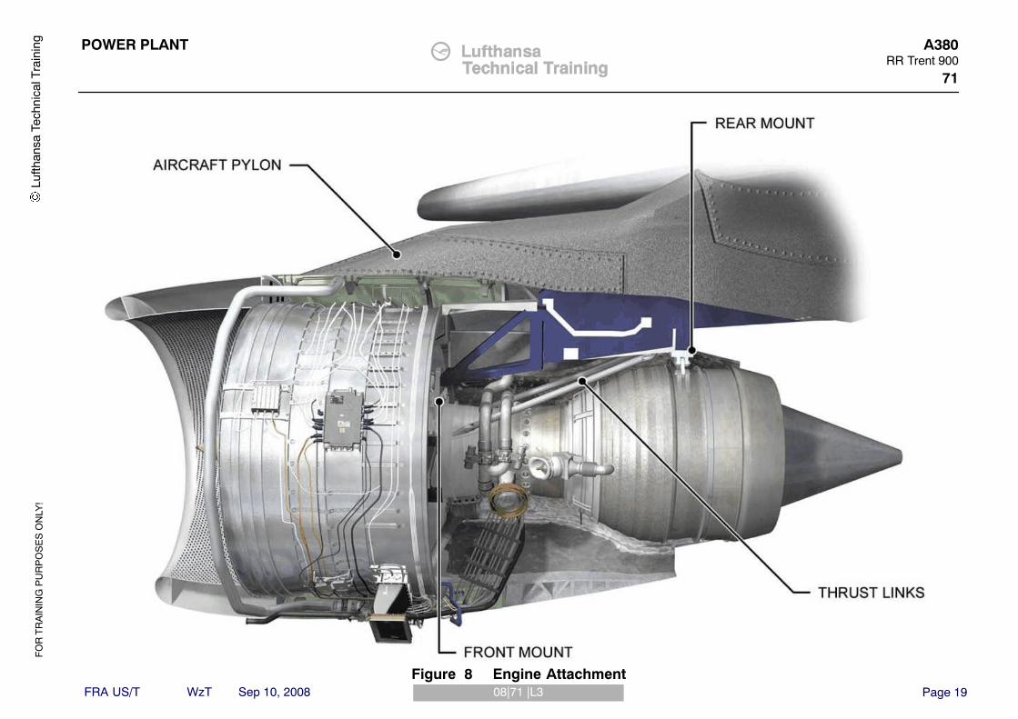
ENGINE ATTACHMENT
DescriptionThe engine is core mounted and attached to the Aircraft pylon by:� Front Mount� Thrust Links� Rear Mount
The engine mounts transmit the engine loads and thrust to the Aircraft pylon.
Lufth
ansa
Tec
hnic
al T
rain
ing
FO
R T
RA
ININ
G P
UR
PO
SE
S O
NLY
!
Page 1908|71 |L3
POWER PLANT A380RR Trent 900
71
FRA US/T WzT Sep 10, 2008
Lufth
ansa
Tec
hnic
al T
rain
ing
Figure 8 Engine Attachment

FO
R T
RA
ININ
G P
UR
PO
SE
S O
NLY
!
Page 2009|71 |L3
POWER PLANT A380RR Trent 900
71
FRA US/T WzT Sep 10, 2008
ENGINE MOUNTS
PurposeThe mounts support the weight of the engine and transmit loads to the Aircraftstructure.
Front MountThe engine front mount is installed on the top of the intermediate case andattaches to the Aircraft pylon with six tension bolts. The front mount transmitsthe following loads to the Aircraft pylon:� Vertical� Side
Thrust LinksThe thrust links transmit the thrust from the intermediate case to the undersideof the pylon just forward of the rear mount attachment.
Rear MountThe engine rear mount is installed on top of turbine exhaust case and attachesto the Aircraft pylon via a pylon adapter beam with four tension bolts. The rearmount transmits the following loads to the Aircraft pylon:� Vertical� Side� Torsion
Lufth
ansa
Tec
hnic
al T
rain
ing

FO
R T
RA
ININ
G P
UR
PO
SE
S O
NLY
!
Page 2109|71 |L3
POWER PLANT A380RR Trent 900
71
FRA US/T WzT Sep 10, 2008
Lufth
ansa
Tec
hnic
al T
rain
ing
Figure 9 Engine Mounts

FO
R T
RA
ININ
G P
UR
PO
SE
S O
NLY
!
Page 2210|71 |L2
POWER PLANT A380RR Trent 900
71
FRA US/T WzT Sep 10, 2008
ENGINE DRAINS
DescriptionThe drains system collects and discards unused fuel and other fluids that canleak from certain engine units and from certain engine areas.The drain system collects leakage from the following systems:� Fuel� Oil� Hydraulic
Fuel System DrainsA drains tank is installed on the right side of the LP compressor case, justabove the HMU, and it collects fuel from the fuel manifold when the engine isshut down on the ground. The contents of the drains tank are drawn back intothe main fuel system during subsequent engine running via a self−consumingdrains system, consisting of a float valve and an ejector valve, which is locatedin the base of the drains tank. A float within the tank prevents the ingress of airinto the system when the level falls. Should the tank become full an overflowpipe carries surplus fuel to the drains mast.Drain lines take fuel from the following components to the drains mast:� Fuel pump mounting pad� Variable stator vane actuators (VSVA)� Fuel drains tank overflow
Oil DrainsDrain lines take oil from the following components to the drains mast:� Oil tank filler scupper� Air starter mounting pad� Variable Frequency Generator (VFG)
Hydraulic SystemDrain lines take hydraulic fluid to the drains mast from the inboard andoutboard hydraulic pump mounting pads and pump seal cavity.
Other DrainsThere is a pipe from the lower splitter fairing in Zone 2, to allow drainageoverboard in the event of leakage or water ingestion. This drain exits through ahole in the C−duct latch access panel between latches 1 & 2.The turbine case drain is provided to drain any residual fuel left in the turbinearea following a wet crank or start attempt when the engine fails to light up.The drain pipe exits through a hole in the C−duct latch access panel just to therear of latch 6.A duct incorporated within the interservice bifurcation panel provides drainagefrom Zone 3 through a hole in the C duct latch access panel between latches 1and 2There are also forward and rear pylon drains which drain fluid overboardthrough holes in the latch access panel just to the rear of latch 6.
Lufth
ansa
Tec
hnic
al T
rain
ing

FO
R T
RA
ININ
G P
UR
PO
SE
S O
NLY
!
Page 2310|71 |L2
POWER PLANT A380RR Trent 900
71
FRA US/T WzT Sep 10, 2008
Lufth
ansa
Tec
hnic
al T
rain
ing
Figure 10 Drains System

FO
R T
RA
ININ
G P
UR
PO
SE
S O
NLY
!
Page 2411|71 |L2
POWER PLANT A380RR Trent 900
71
FRA US/T WzT Sep 10, 2008
Drain System Leakage RatesTo be sure that an engine operates correctly, the leakage rates at drain masthave to be monitored, checked and measured. The leakage rates for eachsystem have to be within the acceptable limits specified by the enginemanufacturer. If this is not the case, further troubleshooting is necessary toidentify the source of the leak.Lu
fthan
sa T
echn
ical
Tra
inin
g

FO
R T
RA
ININ
G P
UR
PO
SE
S O
NLY
!
Page 2511|71 |L2
POWER PLANT A380RR Trent 900
71
FRA US/T WzT Sep 10, 2008
Lufth
ansa
Tec
hnic
al T
rain
ing
Figure 11 Drain System − Leakage Rates

FO
R T
RA
ININ
G P
UR
PO
SE
S O
NLY
!
Page 2612|71 |L3
POWER PLANT A380RR Trent 900
71
FRA US/T WzT Sep 10, 2008
DRAINS MAST AND BREATHER OUTLET
The drains mast and breather outlet are attached to a bracket on the rear faceof the external gearbox. The drains mast is on the split line between the twofan cowl doors.The breather outlet from the centrifugal breather and other drains areannotated on the drains mast.
Lufth
ansa
Tec
hnic
al T
rain
ing

FO
R T
RA
ININ
G P
UR
PO
SE
S O
NLY
!
Page 2712|71 |L3
POWER PLANT A380RR Trent 900
71
FRA US/T WzT Sep 10, 2008
Lufth
ansa
Tec
hnic
al T
rain
ing
Figure 12 Drains Mast

FO
R T
RA
ININ
G P
UR
PO
SE
S O
NLY
!
Page 2813|71 |L3
POWER PLANT A380RR Trent 900
71
FRA US/T WzT Sep 10, 2008
DRAINS TANK
PurposeTo prevent the formation of coking deposits within the fuel spray nozzlemanifold drains system to give increased HMU and float valve/ejector valvereliability.
Drains Tank LocationThe drains tank is installed on a bracket on the lower right side of the fan case,between the Fuel Oil Heat Exchanger (FOHE) and the Hydro Mechanical Unit(HMU).
Lufth
ansa
Tec
hnic
al T
rain
ing

FO
R T
RA
ININ
G P
UR
PO
SE
S O
NLY
!
Page 2913|71 |L3
POWER PLANT A380RR Trent 900
71
FRA US/T WzT Sep 10, 2008
Lufth
ansa
Tec
hnic
al T
rain
ing
Figure 13 Drains Tank Location

FO
R T
RA
ININ
G P
UR
PO
SE
S O
NLY
!
Page 3014|71 |L3
POWER PLANT A380RR Trent 900
71
FRA US/T WzT Sep 10, 2008
DRAINS TANK OPERATION
Unlike previous RB211 / Trent designs there is no dedicated drain line from thefuel spray nozzle manifold. When the HMU drains valve is opened, fuel isdrained directly from the main HP fuel line.When the engine is shut down, or after failure to start on the ground, fuel isdrained from the fuel manifold. As fuel flows into the tank air is releasedthrough the outlet tube.After a number of failed starts, the tank can become full of drained fuel; thisfuel is then discharged through the outlet tube to the drains mast.During normal operation, fuel in the drains tank lifts the float valve and moves itto the open position. During engine starting LP fuel flows through the ejector,this will lower the fuel pressure in the ejector to less than that in the tank andthe non−return valve opens. This allows fuel to be removed from the tank androuted to the inlet side of the LP pump.When the fuel in the tank falls to a certain level the float valve closespreventing air being introduced into the LP fuel supply.
Lufth
ansa
Tec
hnic
al T
rain
ing

FO
R T
RA
ININ
G P
UR
PO
SE
S O
NLY
!
Page 3114|71 |L3
POWER PLANT A380RR Trent 900
71
FRA US/T WzT Sep 10, 2008
Lufth
ansa
Tec
hnic
al T
rain
ing
Figure 14 Drains Tank Operation

FO
R T
RA
ININ
G P
UR
PO
SE
S O
NLY
!
Page 3215|71 |L3
POWER PLANT A380RR Trent 900
71
FRA US/T WzT Sep 10, 2008
PYLON ELECTRICAL DISCONNECTS
There are 18 separate harness electrical connectors between the engine /nacelle mounted components and the pylon. The connectors are keyed tocorrectly align the connector with its mating receptacle and to prevent crossconnection.The powerplant harnesses are colour coded by having braids of differentcolours, known as tracer colours. These are used to identify the harness andfollow its route. They also assist in identifying the FADEC systems harnessesfrom those of other systems.The illustration opposite shows the harness numbers and the pylon connectorsto which they attach. It also shows the units which are connected by eachharness.
Lufth
ansa
Tec
hnic
al T
rain
ing

FO
R T
RA
ININ
G P
UR
PO
SE
S O
NLY
!
Page 3315|71 |L3
POWER PLANT A380RR Trent 900
71
FRA US/T WzT Sep 10, 2008
Lufth
ansa
Tec
hnic
al T
rain
ing
Figure 15 Pylon / Powerplant Electrical Disconnects

FO
R T
RA
ININ
G P
UR
PO
SE
S O
NLY
!
Page 3416|71 |L3
POWER PLANT A380RR Trent 900
71
FRA US/T WzT Sep 10, 2008
PYLON ELECTRICAL RECEPTACLES & CONNECTORS
VFG Cable and ZoneThe illustrations below show the following electrical disconnects:The VFG power cables junction block on the upper left side of the fan case.The receptacles and harness connectors above the left side of the engine core.
Fan Case to PylonThe illustrations below show the receptacles and harness connectors abovethe left side of the fan case. There are two groups of connections in this area.
Lufth
ansa
Tec
hnic
al T
rain
ing

FO
R T
RA
ININ
G P
UR
PO
SE
S O
NLY
!
Page 3516|71 |L3
POWER PLANT A380RR Trent 900
71
FRA US/T WzT Sep 10, 2008
ELECTRICALCONNECTOR5012VCA
ELECTRICALCONNECTOR5013VCA
ELECTRICAL CONNECTOR5014VCA
FAN CASE TO PYLON ELECTRICAL CONNECTION
VFG CABLE AND ZONE ELECTRICAL CONNECTION
Lufth
ansa
Tec
hnic
al T
rain
ing
Figure 16 Electrical Connectors

FO
R T
RA
ININ
G P
UR
PO
SE
S O
NLY
!
Page 3601 |72 |L3
POWER PLANTENGINE
A380RR TRENT 900
72
FRA US/T WzT Sep 10, 2008
ATA 72 ENGINE
MAIN ROTATING ASSEMBLIES
DescriptionThe three rotating assemblies comprise:� Low Pressure (LP) compressor (fan) connected by a shaft to a five−stage
turbine.� Intermediate pressure (IP) compressor connected by a shaft to a single
stage turbine.� High Pressure (HP) compressor connected by a shaft to a single stage
turbine.Roller bearings and ball (location) bearings support each shaft.The external gearbox is driven from the HP shaft through an internal gearboxand an intermediate (step−aside) gearbox.
Lufth
ansa
Tec
hnic
al T
rain
ing

FO
R T
RA
ININ
G P
UR
PO
SE
S O
NLY
!
Page 3701 |72 |L3
POWER PLANTENGINE
A380RR TRENT 900
72
FRA US/T WzT Sep 10, 2008
Lufth
ansa
Tec
hnic
al T
rain
ing
Figure 17 Main Rotating Assemblies

FO
R T
RA
ININ
G P
UR
PO
SE
S O
NLY
!
Page 3802 |72 |L3
POWER PLANTENGINE
A380RR TRENT 900
72
FRA US/T WzT Sep 10, 2008
ENGINE MAIN BEARING ARRANGEMENTThe LP and IP rotor assemblies are each supported by three bearings. The HProtor is supported by two bearings.Two types of bearings are used in this engine, ball bearings for shaft locationand roller bearings providing shaft radial support whilst allowing axial thermalmovement. The bearings are located in 4 bearing housings.The location bearings for all three shafts are positioned in the intermediatecase module.The front bearing housing contains the LP compressor and IP compressorroller bearings.The Internal gearbox contains the three thrust or location ball bearingassemblies.The HP/IP Turbine bearing housing contains the HP turbine and IP turbineroller bearings.The Tail Bearing Housing (TBH) contains the LP turbine roller bearing.
Lufth
ansa
Tec
hnic
al T
rain
ing

FO
R T
RA
ININ
G P
UR
PO
SE
S O
NLY
!
Page 3902 |72 |L3
POWER PLANTENGINE
A380RR TRENT 900
72
FRA US/T WzT Sep 10, 2008
Lufth
ansa
Tec
hnic
al T
rain
ing
Figure 18 Engine Bearing Arrangenment

FO
R T
RA
ININ
G P
UR
PO
SE
S O
NLY
!
Page 4003 |72 |L3
POWER PLANTENGINE
A380RR TRENT 900
72
FRA US/T WzT Sep 10, 2008
TRENT MODULAR BREAKDOWNThe Trent engine consists of eight modules as follows:� Module 01 (31) − LP Compressor Rotor� Module 02 (32) − IP Compressor� Module 03 (33) − Intermediate Case� Module 04 (41) − HP System� Module 05 (51) − IP Turbine� Module 06 (61) − External Gearbox� Module 07 (34) − LP Compressor Case� Module 08 (52) − LP Turbine
The numbers in parentheses are the ATA numbers relating to modules, asused in the Engine Manual.The fan blades are non−modular items but can be considered as part ofmodule 01 (31).The modular construction gives several important benefits:� Decreased turn−round time for repair� Lower overall maintenance costs� Reduced spare engine holdings� Maximum life achieved from each module� Savings on transport costs� Ease of transport and storage� On−wing test capability after any module change
The engine is completed by the addition of various non−modular items andsystems e.g. fuel, oil etc.Modules 01, 02, 03, 04, 05 and 08 form the core engine module.
Lufth
ansa
Tec
hnic
al T
rain
ing

FO
R T
RA
ININ
G P
UR
PO
SE
S O
NLY
!
Page 4103 |72 |L3
POWER PLANTENGINE
A380RR TRENT 900
72
FRA US/T WzT Sep 10, 2008
Lufth
ansa
Tec
hnic
al T
rain
ing
Figure 19 Modular Breakdown

FO
R T
RA
ININ
G P
UR
PO
SE
S O
NLY
!
Page 4204 |72 |L3
POWER PLANTENGINE
A380RR TRENT 900
72
FRA US/T WzT Sep 10, 2008
LP COMPRESSOR
DescriptionThe LP compressor consists of the fan disc and fan shaft. The fan blades andannulus fillers, are non−modular but considered to be included in this module.Fan DiscThe fan disc is a titanium disc with axial ”dovetail” slots for blade fitment. Eachblade is held in the disc with a shear key. The disc incorporates a drive armthat connects to the rotor shaft with a curvic coupling. The disc alsoincorporates annulus filler location lugs as integral features.
LP Compressor ShaftThe LP compressor (fan) shaft connects to the fan disc through a curviccoupling that provides accurate location. The coupling is secured by a ring ofbolts, which thread into captive nuts on the LP compressor roller bearing innerrace, which is secured to the shaft by an interference fit in addition to the bolts.The bearing race also incorporates the front bearing housing oil seal and aphonic wheel for measurement of LP speed. The shaft connects to the LPturbine shaft through a helical spline coupling.A failsafe shaft is fitted inside the LP compressor shaft and secured to the LPturbine shaft by a collar and nut.
LP Compressor BladesThe 24 wide chord titanium fan blades incorporate an inner platform with adovetail feature for location in the disc. The blades are retained axially in thedisc by a shear key.
Annulus FillersThere are 24 aluminium annulus fillers located between each fan blade, whichprovide an aerodynamic profile at the base of each blade. The annulus fillersare installed onto the fan disc lugs and the located by a dowel into the rearspinner rear flange.
Lufth
ansa
Tec
hnic
al T
rain
ing

FO
R T
RA
ININ
G P
UR
PO
SE
S O
NLY
!
Page 4304 |72 |L3
POWER PLANTENGINE
A380RR TRENT 900
72
FRA US/T WzT Sep 10, 2008
Lufth
ansa
Tec
hnic
al T
rain
ing
Figure 20 LP Compressor Module
FO
R T
RA
ININ
G P
UR
PO
SE
S O
NLY
!
Page 4405 |72 |L3
POWER PLANTENGINE
A380RR TRENT 900
72
FRA US/T WzT Sep 10, 2008
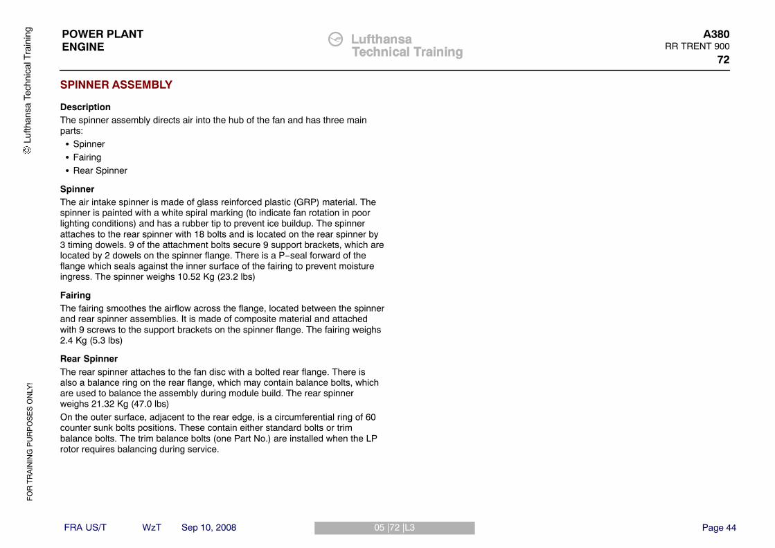
SPINNER ASSEMBLY
DescriptionThe spinner assembly directs air into the hub of the fan and has three mainparts:� Spinner� Fairing� Rear Spinner
SpinnerThe air intake spinner is made of glass reinforced plastic (GRP) material. Thespinner is painted with a white spiral marking (to indicate fan rotation in poorlighting conditions) and has a rubber tip to prevent ice buildup. The spinnerattaches to the rear spinner with 18 bolts and is located on the rear spinner by3 timing dowels. 9 of the attachment bolts secure 9 support brackets, which arelocated by 2 dowels on the spinner flange. There is a P−seal forward of theflange which seals against the inner surface of the fairing to prevent moistureingress. The spinner weighs 10.52 Kg (23.2 lbs)
FairingThe fairing smoothes the airflow across the flange, located between the spinnerand rear spinner assemblies. It is made of composite material and attachedwith 9 screws to the support brackets on the spinner flange. The fairing weighs2.4 Kg (5.3 lbs)
Rear SpinnerThe rear spinner attaches to the fan disc with a bolted rear flange. There isalso a balance ring on the rear flange, which may contain balance bolts, whichare used to balance the assembly during module build. The rear spinnerweighs 21.32 Kg (47.0 lbs)On the outer surface, adjacent to the rear edge, is a circumferential ring of 60counter sunk bolts positions. These contain either standard bolts or trimbalance bolts. The trim balance bolts (one Part No.) are installed when the LProtor requires balancing during service.
Lufth
ansa
Tec
hnic
al T
rain
ing

FO
R T
RA
ININ
G P
UR
PO
SE
S O
NLY
!
Page 4505 |72 |L3
POWER PLANTENGINE
A380RR TRENT 900
72
FRA US/T WzT Sep 10, 2008
Lufth
ansa
Tec
hnic
al T
rain
ing
Figure 21 Spinner / Fairing Assembly

FO
R T
RA
ININ
G P
UR
PO
SE
S O
NLY
!
Page 4606 |72 |L3
POWER PLANTENGINE
A380RR TRENT 900
72
FRA US/T WzT Sep 10, 2008
FAN BLADE ASSEMBLY
DescriptionThe LP compressor has 24 wide−chord, hollow, titanium fan blades,incorporating low speed swept fan aerodynamics for efficiency and noise. Theassembly consists of the following parts:� fan blade� shear key� slider assembly� annulus filler
The fan blades fit into dovetail slots in the LP compressor disc. Each blade isaxially located by a shear key, which fits into a slot in the disc. A rubber strapon the base of the blade dovetail holds the shear key on the blade.A slider assembly fits in the dovetail slot at the end of each blade and ensuresthat the shear key is located in the slot in the disc.The annulus fillers provide an aerodynamic profile between adjacent fanblades. They are manufactured in aluminium and incorporate retention lugs,which mate with the disc lugs for location. They also incorporate a rubber stripon both sides, which abut the airfoil surface of the fan blade. Axial retention ofthe annulus fillers is provided by the rear spinner assembly, which locates eachannulus filler by a dowel through the rear flange.
Lufth
ansa
Tec
hnic
al T
rain
ing

FO
R T
RA
ININ
G P
UR
PO
SE
S O
NLY
!
Page 4706 |72 |L3
POWER PLANTENGINE
A380RR TRENT 900
72
FRA US/T WzT Sep 10, 2008
Lufth
ansa
Tec
hnic
al T
rain
ing
Figure 22 Fan Blade

FO
R T
RA
ININ
G P
UR
PO
SE
S O
NLY
!
Page 4807 |72 |L3
POWER PLANTENGINE
A380RR TRENT 900
72
FRA US/T WzT Sep 10, 2008
IP COMPRESSOR
DescriptionThe IP compressor module is an eight stage axial assembly consisting of fourmain sections:� Front bearing housing� The IP compressor stage 1 - 4 case� The IP compressor stage 5 - 8 case� The IP compressor rotor
Front Bearing Housing (FBH)The front bearing housing includes a hub, which locates the LP and IPcompressor bearings and an oil sump, also the LP and IP shaft speed probes.Connected to the hub are the engine section stator vanes (ESS) or fixed inletguide vanes. The vanes are welded together as one unit and there are lugs onthe outer ring. These lugs are connected to the FOGV torsion ring to make theFBH/OGV joint. This FBH/OGV joint holds the LP compressor case to the coreengine. The electrical cables, from the shaft speed probes, pass internallythrough the ESS vanes. Other vanes contain tubes to supply oil to and fromthe roller bearings. Behind the ESS vanes are the variable inlet guide vanes.
IP Compressor Stage 1 - 4 CaseThe stage 1 to 4 case is connected to the FBH at the front and to the stage 5to 8 case at the rear. The case is divided into two semi−circular titanium halfcases. The stage 1 and 2 vanes are variable with spindles on the outersurface, which are connected by levers and unison rings to the VIGV/VSVoperating mechanism. The stage 3 and 4 vanes are fixed and located in T slotsaround the inner circumference of the half cases. Between the stator vanepositions on the inner surface there are abradable linings, located opposite tothe rotor blade tracks.
IP Compressor Stage 5 - 8 CaseThe IP compressor case is flanged and bolted to the rear of the stage 1 to 4case and is made of steel and contains stages 5 to 8 of the compressor. Thecase is divided into two semi−circular half cases. The stage 5 to 8 vanes aremade of nickel alloy and installed in T slots around the inner circumference ofthe half cases. The stage 8 stator vanes are also known as the IP compressoroutlet guide vanes (OGV‘s).
IP Compressor RotorThe IP compressor rotor is an assembly of eight titanium rotor discs, inbetween the discs of stages 1, 2 & 3 there are spacers that have interstageseal fins. The discs at stages 1 to 6 have axial dovetail slots into which therotor blades are installed. Retaining plates and lock plates keep the blades inposition. At stages 7 and 8 the blades are installed in circumferential dovetailslots. These blades are locked in position with nut and screw lock assemblies.The IP front stubshaft is attached to the stage 1 disc with bolts, the forwardend of the stubshaft has a phonic wheel for IP speed measurement.The stage 6 disc incorporates a drive arm with a curvic coupling to which therear stubshaft is attached. Splines in the stubshaft engage with splines on theIP turbine shaft.
Lufth
ansa
Tec
hnic
al T
rain
ing

FO
R T
RA
ININ
G P
UR
PO
SE
S O
NLY
!
Page 4907 |72 |L3
POWER PLANTENGINE
A380RR TRENT 900
72
FRA US/T WzT Sep 10, 2008
Lufth
ansa
Tec
hnic
al T
rain
ing
Figure 23 IP Compressor

FO
R T
RA
ININ
G P
UR
PO
SE
S O
NLY
!
Page 5008 |72 |L3
POWER PLANTENGINE
A380RR TRENT 900
72
FRA US/T WzT Sep 10, 2008
INTERMEDIATE CASEThe intermediate case is one of the major structural parts of the engine andmade from two titanium cylindrical casings, which are welded together. In therear half, behind the weld, there are ten equally spaced radial struts, whichsupport an inner structure. The IP and HP location bearings and the internalgearbox are attached to the inner structure. Two lugs on the rear case, abovethe radial struts, transmit engine thrust through struts to the airframe pylon.The front part of the intermediate case has a stronger area at the top, whichincludes lugs for the attachment of the front engine mount. Above and belowthe center−line there are symmetrical positions for the installation of the Aframe struts. The two A frame struts on each side of the case align with theinstallation point on each side of the LP compressor case. Below the enginehorizontal center line on the intermediate case, there are borescope accessholes, which align with related holes in the compressor cases.The radial struts, which have an aerofoil shape, are hollow. Some of the vanescontain tubes, which supply oil to and from the internal gearbox. The externalgearbox drive shaft, which transmits power to the External Gearbox (EGB), isin one of the struts. Other struts supply compressor air to cool the HP/IP andLPT bearing chambers and seal the EGB accessory mount pads.The front part of the intermediate case is installed around the Stage 5 to 8 caseand is connected to a flange around the middle of the stage 1 to 4 case. Therear part of the intermediate case is installed around the front part of the HPcompressor case. The rear of the intermediate case is connected to thecombustion outer case. There is also a bayonet connection from an internalflange at the rear of the intermediate case to the HP compressor case. Innerand outer walls make an annulus, through which the air flows from the IPcompressor to the HP compressor.
Lufth
ansa
Tec
hnic
al T
rain
ing

FO
R T
RA
ININ
G P
UR
PO
SE
S O
NLY
!
Page 5108 |72 |L3
POWER PLANTENGINE
A380RR TRENT 900
72
FRA US/T WzT Sep 10, 2008
Lufth
ansa
Tec
hnic
al T
rain
ing
Figure 24 Intermediate Case

FO
R T
RA
ININ
G P
UR
PO
SE
S O
NLY
!
Page 5209 |72 |L3
POWER PLANTENGINE
A380RR TRENT 900
72
FRA US/T WzT Sep 10, 2008
HP SYSTEM
DescriptionThe system comprises:� HP compressor� Combustion chamber and outer case� HP turbine
HP CompressorThe HP compressor rotor is a six−stage assembly. Stages 1 to 4 are made ofheat resistant alloy discs welded together to form one drum. The stage 5 disc isalso heat resistant alloy. The stage 6 disc and rear cone are made of heatresistant alloy and welded together. The first stage blades are made of titaniumand installed in axial dovetail slots and are locked with retaining plates. Stages2 to 6 are made of heat resistant alloy and installed in circumferential dovetailslots and locked with nuts and screws.The heat resistant alloy cone, which tapers rearwards is inertia bonded to therear of the stage 6 disc. At the rear of this cone is a mini disc to which the HPturbine is connected.The HP compressor case is an assembly of six flanged, cylindrical casingsbolted together. The flanged joints are also the location for the rotor pathabradable linings. There are slots in this assembly for the installation of thestator vanes.The stage 6 stator vanes are also the HP compressor outlet guide vanes(OGVs). These are installed at the entrance of the combustion chamber innercase.
Combustion Chamber and Outer CaseThe outer case is flanged and bolted to the rear of the intermediate case and tothe front of the IP turbine module. There are 20 openings through which thefuel spray nozzles are installed. There are also two igniter plugs installedthrough bosses in the combustion outer case. The combustion chamber is fullyannular and consists of a tiled liner that is located inside the combustionchamber inner case. At the front of the inner case are the HP compressoroutlet guide vanes (OGVs) and at its rear are the HP turbine nozzle guidevanes (NGVs).
HP TurbineThe HP turbine is a single stage disc connected to a mini disc to the rear of theHP compressor drum. On the rear of the disc there is a stubshaft, which isinertia bonded to the disc. The disc has fir tree roots into which fit the turbineblades. Adjacent to the casing rear flange is a turbine case cooling (TCC) airmanifold.
Lufth
ansa
Tec
hnic
al T
rain
ing

FO
R T
RA
ININ
G P
UR
PO
SE
S O
NLY
!
Page 5309 |72 |L3
POWER PLANTENGINE
A380RR TRENT 900
72
FRA US/T WzT Sep 10, 2008
Lufth
ansa
Tec
hnic
al T
rain
ing
Figure 25 HP System

FO
R T
RA
ININ
G P
UR
PO
SE
S O
NLY
!
Page 5410 |72 |L3
POWER PLANTENGINE
A380RR TRENT 900
72
FRA US/T WzT Sep 10, 2008
IP TURBINE
DescriptionThe IP turbine case houses the IP turbine and IP NGVs, LP turbine stage 1NGVs and the HP/IP bearing housing. The front flange bolts to the combustionouter case and the rear flange bolts to the front flange of the LP turbine module(52).The IP turbine NGVs are hollow. In alternate NGVs there is a strut that isattached to the turbine case by a bolt. The inner end of each strut is connectedto the structure that holds the HP/IP bearing support assembly. Through someof the other NGVs are tubes to supply oil to and from the bearings and IP 8cooling air to cool the housing.The IP turbine is a single stage turbine assembly. At the hub of the disc a drivearm extends rearwards, which connects to the IP turbine shaft and stub shaftusing taper bolts The IP turbine shaft runs forward and is connected to the IPcompressor stub shaft with helical splines. The IP stubshaft runs forward toengage with the IP turbine roller bearing.The disc has fir tree roots into which fit the turbine blades.Adjacent to the rear flange is a turbine case cooling (TCC) air manifold andlocation bosses for fourteen thermocouples. To the rear of the turbine bladesare the LP1 NGVs.
Lufth
ansa
Tec
hnic
al T
rain
ing

FO
R T
RA
ININ
G P
UR
PO
SE
S O
NLY
!
Page 5510 |72 |L3
POWER PLANTENGINE
A380RR TRENT 900
72
FRA US/T WzT Sep 10, 2008
Lufth
ansa
Tec
hnic
al T
rain
ing
Figure 26 IP Turbine

FO
R T
RA
ININ
G P
UR
PO
SE
S O
NLY
!
Page 5611 |72 |L3
POWER PLANTENGINE
A380RR TRENT 900
72
FRA US/T WzT Sep 10, 2008
LP TURBINE
DescriptionThe LP turbine has five discs which are bolted together to form a drum. Thestage 4 disc acts as the drive arm and attaches to the turbine shaft with acurvic coupling. Also attached to the drive arm on the rear face is a stub shaftthat connects the LP turbine to the LP roller bearing in the tail bearing housingto provide radial support. The stub shaft also connects to a phonic wheel shaftassembly for LP turbine shaft speed measurement.The discs have fir tree roots into which fit the turbine blades.The LP turbine case is a one−piece cylinder flanged and bolted between the IPturbine case at the front, and the exhaust outer case at the rear. Around thecase is a cooling duct through which cooling air flows. On the inner surfacebetween the NGV locations there are seal segments which touch the turbineblade shrouds.In front of each stage of turbine blades there is a stage of NGVs. The firststage of NGVs, which are hollow, are installed as 3 vane sets in the outlet fromthe IP turbine case. One vane in fourteen of the sets contains an EGTthermocouple and one set includes an overheat detector and one set includesa borescope access hole. Stages 2, 3, 4 and 5 NGVs are hollow and areinstalled in the LP turbine case. At the inner ends of the NGVs are honeycombliners, which touch the fins of the interstage seals between the rotor discs.The LP turbine shaft goes forward through the center of the IP shaft andconnects with the LP compressor shaft with splines.The tail bearing housing support structure includes a hub that is held concentricin an outer case by 14 radial hollow vanes. Some of the vanes contain tubesthat supply oil to and from the bearing housing. There is also a supply of IP 8air to cool and seal the bearing.One of the vanes has a pressure inlet in the leading edge to measure LPturbine outlet pressure (P50). LP turbine outlet pressure is used for healthmonitoring. The front flange of the case is attached with bolts to the rear flangeof the LP turbine case. At the rear flange to the primary exhaust nozzle aroundthe case are two flanges to increase the strength. Attached to these flanges, atthe top, is the rear mount.
Lufth
ansa
Tec
hnic
al T
rain
ing

FO
R T
RA
ININ
G P
UR
PO
SE
S O
NLY
!
Page 5711 |72 |L3
POWER PLANTENGINE
A380RR TRENT 900
72
FRA US/T WzT Sep 10, 2008
Lufth
ansa
Tec
hnic
al T
rain
ing
Figure 27 LP Turbine

FO
R T
RA
ININ
G P
UR
PO
SE
S O
NLY
!
Page 5812 |72 |L3
POWER PLANTENGINE
A380RR TRENT 900
72
FRA US/T WzT Sep 10, 2008
EXTERNAL GEARBOX
DescriptionThe external gearbox is a one−piece aluminium gearcase. It is installed on thelower part of the LP compressor case. The gearbox assembly transmits powerfrom the engine to provide drives for the accessories mounted on the gearboxfront and rear faces. During engine starting the gearbox also transmits powerfrom the air starter motor to the engine.The gearbox also provides a means of hand turning the HP rotor system formaintenance purposes.The gearbox is driven from the HP rotor via a transmission system, consistingof an Intermediate gearbox (step−aside gearbox), an external gearbox driveshaft (radial drive) and lower bevel gearbox.The drive shafts for the installed accessories are sealed by non−contact airblown labyrinth seals fed with IP8 air. All the accessory interfaces are protectedby a drains system.Components Installed on the Front Face� Dedicated Alternator� Air Starter Motor� Hand turning point� 2 Hydraulic Pumps
Components Installed on the Rear Face� Variable Frequency Generator (VFG)� Lower bevel gearbox� Oil Pumps� Centrifugal Breather� LP/HP Fuel Pumps� Hydro−Mechanical Unit (HMU)
Lufth
ansa
Tec
hnic
al T
rain
ing

FO
R T
RA
ININ
G P
UR
PO
SE
S O
NLY
!
Page 5912 |72 |L3
POWER PLANTENGINE
A380RR TRENT 900
72
FRA US/T WzT Sep 10, 2008
Lufth
ansa
Tec
hnic
al T
rain
ing
Figure 28 External Gearbox

FO
R T
RA
ININ
G P
UR
PO
SE
S O
NLY
!
Page 6013 |72 |L3
POWER PLANTENGINE
A380RR TRENT 900
72
FRA US/T WzT Sep 10, 2008
LP COMPRESSOR CASE
DescriptionThe LP compressor casing assembly consists of three main sections:� Front Fan Case� Rear Fan Case� Fan Outlet Guide Vanes
Front Fan CaseThe containment case (front) and the center case are manufactured fromtitanium and are welded together to form the front fan case. The containmentcase has circumferential stiffening ribs (3 off), which provide reinforcement inthe fan track region where additional energy absorption is required in the eventof an LP compressor blade release. The front case has the following liningsattached to the inner surface:� Acoustic panels (4)� Attrition lining� Ice impact area� Acoustic perforate skin
Rear Fan CaseThe rear fan case is made from a titanium honeycomb structure. Two titaniumsupports (A frames), located on the horizontal centerline, connect the rear caseto the core engine. On the rear outer edge of the case, there is a “V“ groove,which provides axial location of the thrust reverser.There is an opening in the left side of the case for the Variable FrequencyGenerator (VFG) Air Cooled Oil Cooler. There is also a large opening at BDCfor the external gearbox drive shaft.
Fan Outlet Guide Vanes (OGV‘s)The OGV outer ring is attached at the rear of the front case with bolts. The 52OGV‘s are hollow titanium vanes filled with blue filler. The vanes are installed atequal distance around the circumference and the inner ends are welded to aninner ring.
Lufth
ansa
Tec
hnic
al T
rain
ing

FO
R T
RA
ININ
G P
UR
PO
SE
S O
NLY
!
Page 6113 |72 |L3
POWER PLANTENGINE
A380RR TRENT 900
72
FRA US/T WzT Sep 10, 2008
Lufth
ansa
Tec
hnic
al T
rain
ing
Figure 29 LP Compressor Case

FO
R T
RA
ININ
G P
UR
PO
SE
S O
NLY
!
Page 6214 |72 |L3
POWER PLANTENGINE
A380RR TRENT 900
72
FRA US/T WzT Sep 10, 2008
ENGINE CORE FAIRINGS
DescriptionTo ensure a smooth airflow over the parts of the gas generator not covered bythe thrust reverser halves, six removable fairings are fitted around the front partof the IP compressor case.Each fairing panels are a sandwich construction of titanium inner skin andperforated titanium outer skin with a nomex honeycomb core. The outer skin isperforated for noise attenuation. Two ventilation inlet holes are provided, one ineach of the upper panels and two ventilation outlet holes, one in each of thelower panels.The front edge of each fairing is attached to the LP compressor OGV torsionring with bolts secured in floating anchor nuts. The rear edge is attached tomounting brackets on the rear support diaphragm with bolts secured in floatinganchor nuts.
UPPER SPLITTER FAIRING
PurposeTo smooth the fan airflow into the thrust reverser halves and to provide aposition for the fan air pressure rake (P160).
DescriptionThe upper splitter fairing is a carbon and glass composite fairing installedbetween the fan case and the intermediate case support structure. The P160probe rake is installed inside the fairing with its six measuring heads projectinginto the fan duct through holes in the leading edge of the fairing.
LOWER SPLITTER FAIRING
PurposeTo smooth the fan airflow around the external gearbox driveshaft (radial drive)into the thrust reverser halves.
DescriptionThe lower splitter fairing is a carbon and glass composite fairing installedforward of the external gearbox driveshaft assembly, between the fan case andthe intermediate case support structure.
Lufth
ansa
Tec
hnic
al T
rain
ing

FO
R T
RA
ININ
G P
UR
PO
SE
S O
NLY
!
Page 6314 |72 |L3
POWER PLANTENGINE
A380RR TRENT 900
72
FRA US/T WzT Sep 10, 2008
Lufth
ansa
Tec
hnic
al T
rain
ing
Figure 30 Engine Core Fairings

FO
R T
RA
ININ
G P
UR
PO
SE
S O
NLY
!
Page 6415 |72 |L2
POWER PLANTENGINE
A380RR TRENT 900
72
FRA US/T WzT Sep 10, 2008
FAN BLADE CLEANING
PurposeTo maintain the efficiency of the fan it is necessary to clean the fan blades andfan outlet guide vanes (OGV s) at regular intervals.
DescriptionThe procedure is fully described in the AMM 72−00−00 and is briefly describedbelow:Follow all applicable Warnings and Cautions.Note:Depending upon the outside air temperature the washing fluid is a mixture ofdemineralized water, washing fluid (OM−1070) and monopropylene glycol (OM - 1076). Follow the AMM procedure for the applicable ratios.� Use a clean lint−free cloth soaked in the cleaning solution to clean the LP
compressor blades. Makesure you apply the cleaning solution to the frontandthe aft of the blades, and that the blade to becleaned is at bottom deadcenter.
� Let the cleaning solution stay on the surface of theblades for 15 minutes.� Use a clean lint−free cloth soaked in demineralized or distilled water to
remove the cleaning solution fromthe surface of the blades� Examine the blades for dirty areas� If they are not sufficiently clean, repeat the cleaning procedure again� Repeat this process for the fan OGV s.
NOTE:1. It is important that the fan blades are cleaned at bottom dead center to
avoid any dirt migrating into the blade dovetail root area.2. Most the dirt tends to stay on the suction face (rear) of the fan blade and
particular attention should be given to this area.3. Mix the washing fluid at regular 30 minute intervals
Lufth
ansa
Tec
hnic
al T
rain
ing

FO
R T
RA
ININ
G P
UR
PO
SE
S O
NLY
!
Page 6515 |72 |L2
POWER PLANTENGINE
A380RR TRENT 900
72
FRA US/T WzT Sep 10, 2008
Lufth
ansa
Tec
hnic
al T
rain
ing
Figure 31 Fan Blade Cleaning

FO
R T
RA
ININ
G P
UR
PO
SE
S O
NLY
!
Page 6616 |72 |L3
POWER PLANTENGINE
A380RR TRENT 900
72
FRA US/T WzT Sep 10, 2008
INSPECTION OF LPC BLADE & ANNULUS FILLERS
(AMM 72−31−41)
WARNING: YOU MUST MAKE SURE THAT THE APPLICABLE COVERSARE INSTALLED TO THE REAR OF THE ENGINE. THEMOVEMENT OF AIR THROUGH THE ENGINE CAN CAUSETHE LP COMPRESSOR TO TURN VERY QUICKLY ANDCAUSE INJURY.
Preparation:Before carrying out the Inspection carry out the following:� Put a suitable access platform in a safe position� Put a protective rug into the air inlet cowl. (Make sure the red warning
flagcan be seen externally of the air intake).� Install the Immobiliser - LP compressor rotor to prevent movement
Fan Blade InspectionThe blade airfoil surfaces should be inspected for the following types ofdamage:� Cracks� Blade tip & adjacent airfoil surface heat discolouration� Arc−burns� Scratches & dents� Nicks� Blade bends
NOTE: Cracks and arc−burns are not permitted and the affected bladesmust be replaced.
Refer to the Aircraft Maintenance Manual limits for all other damage.
NOTE: The blade is divided into separate areas with different limits foreach.
NOTE: In addition to the normal limits for blade bends, there are fly onlimits − the blade must be replaced within 125 hours or 25 flights(whichever occurs first).
Annulus Filler Inspection:Examine the annulus fillers for the following:� Cracks� Bends� Distortion� Nicks� Scores� Dents� Missing or split air seals
If the annulus fillers are removed then the hooks and ribs should also bechecked for nicks and dents.Cracks, bends and distortion are not allowed. Refer to the AMM for all otherdamage limits.
NOTE: Annulus fillers that are rejected should be replaced withcomponents that are the same weight or almost the sameweight.
Lufth
ansa
Tec
hnic
al T
rain
ing

FO
R T
RA
ININ
G P
UR
PO
SE
S O
NLY
!
Page 6716 |72 |L3
POWER PLANTENGINE
A380RR TRENT 900
72
FRA US/T WzT Sep 10, 2008
Lufth
ansa
Tec
hnic
al T
rain
ing
Figure 32 LPC Blade Inspection

FO
R T
RA
ININ
G P
UR
PO
SE
S O
NLY
!
Page 6817 |72 |L3
POWER PLANTENGINE
A380RR TRENT 900
72
FRA US/T WzT Sep 10, 2008
REMOVAL /INSTALLATION OF THE SPINNER & FAIRING
(AMM 72−35−41)
WARNING: YOU MUST MAKE SURE THAT THE APPLICABLE COVERSARE INSTALLED TO THE REAR OF THE ENGINE. THEMOVEMENT OF AIR THROUGH THE ENGINE CAN CAUSETHE LP COMPRESSOR TO TURN VERY QUICKLY ANDCAUSE INJURY.
Preparation:� Put a suitable access platform in a safe position� Put a protective rug into the air inlet cowl. (Make sure the red warning flag
can be seen externally of the air intake).� Install the Immobiliser (HU44211) - LP compressor rotor to prevent
movement
Removal Procedure:
NOTE: The component weights are as follows:fairing 2.40 Kg (5.3 lb)spinner 10.52 Kg (23.21 lb)
4. Using a temporary marker make an alignment mark across the fairing,spinner, rear spinner and annulus filler
5. Remove the attaching screws and remove the fairing.6. Remove the bolts and brackets securing the spinner7. Install the guide pins (HU44265) Make sure the groove points up (this is to
catch the spinner when it is released from the support ring).8. Install four of the removed bolts in the four extraction bushes and turn the
four bolts in equal increments to release the spinner9. Carefully remove the spinner from the guide pins10.Put the spinner rear edge down on to an applicable flat surface.
CAUTION: YOU MUST NOT HOLD THE NOSE CAP WHEN YOUREMOVE/INSTALL THE AIR INTAKE SPINNER. YOU CANCAUSE DAMAGE TO THE SPINNER.
Installation ProcedureThe installation procedure is the reverse of the removal procedure but youmust make sure of the following points.1. Align the timing pin on the spinner with the hole on the rear spinner2. Torque all bolts to the value stated in the AMM.3. Make sure all equipment is removed and the aircraft is put back to the
correct configuration.
Lufth
ansa
Tec
hnic
al T
rain
ing

FO
R T
RA
ININ
G P
UR
PO
SE
S O
NLY
!
Page 6917 |72 |L3
POWER PLANTENGINE
A380RR TRENT 900
72
FRA US/T WzT Sep 10, 2008
Lufth
ansa
Tec
hnic
al T
rain
ing
Figure 33 Spinner Fairing Removal

FO
R T
RA
ININ
G P
UR
PO
SE
S O
NLY
!
Page 7018 |72 |L3
POWER PLANTENGINE
A380RR TRENT 900
72
FRA US/T WzT Sep 10, 2008
REMOVAL /INSTALLATION OF THE REAR SPINNER
(72−35−41)
Removal Procedure:
NOTE: The spinner weights 21.32 Kg (47.0 lb)Make a record of the positions of any compensation balance weights that areinstalled on the balance flangeInstall the lifting tool handles (HU44445) on the front flange of the rear spinnerHold the rear spinner and remove the attaching bolts and washersInstall the guide pins (HU44265), making sure the groove points up.Install four of the removed bolts in the four extraction bushes and turn the fourbolts in equal increments to release the rear spinnerRemove the rear spinner from the guide pinsPut the rear spinner rear edge down on to an applicable flat surface
Installation ProcedureThe installation procedure is the reverse of the removal procedure but youmust make sure of the following points.Install the lifting tool handles (HU44445) on to the front flange of the rearspinnerAlign the timing pin on the rear spinner with the timing pin hole in the LPcompressor discTorque all bolts to the value stated in the AMM.
Lufth
ansa
Tec
hnic
al T
rain
ing

FO
R T
RA
ININ
G P
UR
PO
SE
S O
NLY
!
Page 7118 |72 |L3
POWER PLANTENGINE
A380RR TRENT 900
72
FRA US/T WzT Sep 10, 2008
Lufth
ansa
Tec
hnic
al T
rain
ing
Figure 34 Rear Spinner Removal

FO
R T
RA
ININ
G P
UR
PO
SE
S O
NLY
!
Page 7219 |72 |L3
POWER PLANTENGINE
A380RR TRENT 900
72
FRA US/T WzT Sep 10, 2008
REMOVAL / INSTALLATION OF THE ANNULUS FILLER
(72−31−41)Removal Procedure4. Using a temporary marker identify the location of each fan blade and each
annulus filler5. To remove the annulus filler, pull the annulus fillers forward to disengage
the hooks from the LP compressor disc, then turn the annulus filler in thedirection of its curve to clear the blades
6. Remove the two annulus fillers on each side of the blade to be removed.
Installation Procedure1. Make sure all grease and debris has been removed from the seals and
mating blade aerofoil surfaces2. Lubricate the rubber seals with 1 part compressor washing fluid (OMat
1070) mixed with 4 parts water
NOTE: Engine Oil can be applied if core washing detergent is notavailable
3. Install the annulus fillers in their initial positions
NOTE: A maximum of 5 replacement annulus fillers can be installedwithout a change to the positions of the full set. If new annulusfillers are installed, the moment weight of each replacement mustbe no more than +10/-10 grams of the removed filler.
4. Make sure the lugs of the annulus filler are fully engaged in the lugs of theLP compressor disc.
5. Make sure the annulus fillers are aligned at the forward end and that therear is located below the rear air seal
NOTE: The information on the annulus filler including serial number, partnumber and weight, is found on the underside at the rear.
Lufth
ansa
Tec
hnic
al T
rain
ing

FO
R T
RA
ININ
G P
UR
PO
SE
S O
NLY
!
Page 7319 |72 |L3
POWER PLANTENGINE
A380RR TRENT 900
72
FRA US/T WzT Sep 10, 2008
Lufth
ansa
Tec
hnic
al T
rain
ing
Figure 35 LP Compresssor Blade Removal

FO
R T
RA
ININ
G P
UR
PO
SE
S O
NLY
!
Page 7420 |72 |L3
POWER PLANTENGINE
A380RR TRENT 900
72
FRA US/T WzT Sep 10, 2008
REMOVAL/INSTALLATION OF THE FAN BLADE
(72−31−41)
WARNING: YOU MUST USE APPLICABLE GLOVES WHEN YOU HOLDTHE FAN BLADES. THE LEADING EDGES OF THE BLADESCAN CAUSE INJURY.
WARNING: YOU MUST MAKE SURE YOU CAN HOLD THE WEIGHT OFTHE COMPONENT BEFORE YOU REMOVE /INSTALL IT. IT ISHEAVY AND CAN CAUSE INJURY TO PERSONS ANDDAMAGE EQUIPMENT.
CAUTION: YOU MUST MAKE SURE THE BLADES DO NOT TOUCHADJACENT BLADES AS DAMAGE CAN BE CAUSED IF THEBLADES TOUCH.
NOTE: The LP Compressor Blade weighs 15.2 Kg (33.5 lb)
Removal Procedure1. Turn the LP rotor so that the blade to be removed is at Bottom Dead Centre
(BDC) and install Immobilizer HU44079 to prevent movement of the out ofbalance fan assembly.
2. Using extracter HU29255 & adapter HU37594 remove the chocking padand slider
3. Lift the blade to disengage the shear key then carefully pull the bladeforward to remove it.
4. Record the radial moment weight of the blade.
Installation Procedure:
CAUTION: BEFORE INSTALLING THE BLADE ALL UNWANTEDMATERIAL MUST BE ROVED FROM THE BLADE DOVETAILAND THE GROOVE IN THE DISC. THE DRY FILM LUBRICANTSHOULD BE INSPECTED AND REPAIRED AS NECESSARY .IF YOU DO NOT DO THIS N1 VIBRATION CAN OCCUR.
1. If a different blade is being fitted then the Moment Weight Difference(MWD) must be calculated.
2. If the MWD is between +80 and −80 oz.in then the installation can proceed.3. If the MWD is more than +80 and −80 oz.in, then the procedure should be
followed to remove the blade opposite to the initial blade removed.4. Install the blade into the slot until the shear key engages.5. Put the slider assembly into the opening of the disc groove above the
blade, push it rearward then fully install using a nylon faced mallet.On completion a vibration survey & fan trim balance is required, unless:
A. You have replaced no more than 3 blades and the MWD is between +8and −8 oz.in of the blade it replaces.
B. You have replaced no more than 5 annulus fillers and the weightdifference is between +10 and −10 grams of the annulus filler itreplaces.
Lufth
ansa
Tec
hnic
al T
rain
ing

FO
R T
RA
ININ
G P
UR
PO
SE
S O
NLY
!
Page 7520 |72 |L3
POWER PLANTENGINE
A380RR TRENT 900
72
FRA US/T WzT Sep 10, 2008
Lufth
ansa
Tec
hnic
al T
rain
ing
Figure 36 LP Compressor Blade Removal

FO
R T
RA
ININ
G P
UR
PO
SE
S O
NLY
!
Page 7621 |72 |L3
POWER PLANTENGINE
A380RR TRENT 900
72
FRA US/T WzT Sep 10, 2008
FAN TRIM BALANCE
Reason for the Job:Some repair work, including fan blade replacement, can affect the balance ofthe Low Pressure (LP) Compressor. The balance of the fan can also changewith time as the engine wears. A fan that is not balanced causes enginevibration.
Trim Balance MethodsThere are two methods of fan trim balance in the AMM:� .The One−Shot Trim Balance� Trial Weight Trim Balance.
The one−shot method uses the data recorded by the Engine Monitoring Unit(EMU) during flight or ground runs and gives the necessary information in orderfor the trim balance weights to be installed in the correct positions to reduce thelevel of vibration of the fan assembly.
NOTE: Flight data should be used where possible, particularly if the fanvibration has been changing with time. Ground data is normallyused if components on the fan have been changed or repairedsince the last flight.
The trial weight method is used if the one−shot method is not giving goodresults and fan vibration remains high. Occasionally some engines exhibitdifferent vibration characteristics to the majority of engines and genericcoefficients cannot be used.
Fan Trim Balance WeightsThe fan trim balance weights are installed on the rear spinner outercircumference near the rear edge. The bolt holes contain either standard boltsor trim balance bolts. All trim balance bolts are the same weight and have thesame part number (the part numbers of the bolts are vibro−engraved on thebolt head).
NOTE: There are 60 positions where trim balance bolts can be installed.The hole positions are numbered counter−clockwise, when youlook at the engine from the front. Their numbers start from theasterisk that identifies hole position No.1.
Description:There is only one part number for trim balance weights. When required, thestandard bolt is removed and replaced by a trim balance weight.The trim balance weights can be identified by the part number on the bolt head,when installed in the rear spinner.Removal of a standard bolt and installation of a trim balance bolt increases themass of the assembly by 13.32 g (0.470 oz.)Mass of standard bolt = 12.36 g (0.436 oz.)Mass of trim balance bolt = 25.68 g (0.906 oz.)
Lufth
ansa
Tec
hnic
al T
rain
ing

FO
R T
RA
ININ
G P
UR
PO
SE
S O
NLY
!
Page 7721 |72 |L3
POWER PLANTENGINE
A380RR TRENT 900
72
FRA US/T WzT Sep 10, 2008
STANDARD BOLT ASSEMBLY BALANCE-WEIGHT ASSEMBLY
Lufth
ansa
Tec
hnic
al T
rain
ing
Figure 37 Fan Trim Balance Weights Position

FO
R T
RA
ININ
G P
UR
PO
SE
S O
NLY
!
Page 7822 |72 |L3
POWER PLANTENGINE
A380RR TRENT 900
72
FRA US/T WzT Sep 10, 2008
BORESCOPE ACCESS PORTS
DescriptionTo inspect the gas path of the engine there are many borescope access portsprovided as follows:� IP Compressor - 4 ports� HP Compressor - 4 ports� Combustion Chamber - 6 ports� HP turbine - 2 ports� IP turbine - 2 ports� LP turbine - 5 ports
NOTE: On the turbine section some ports are used to inspect HP/IP orIP/LP stage 1.
There are a total of 21 borescope access ports, all of which are located on theright side of the engine except for the combustion chamber ports which arelocated radially around the combustion case.
Lufth
ansa
Tec
hnic
al T
rain
ing

FO
R T
RA
ININ
G P
UR
PO
SE
S O
NLY
!
Page 7922 |72 |L3
POWER PLANTENGINE
A380RR TRENT 900
72
FRA US/T WzT Sep 10, 2008
Lufth
ansa
Tec
hnic
al T
rain
ing
Figure 38 Borescope Access Ports

FO
R T
RA
ININ
G P
UR
PO
SE
S O
NLY
!
Page 8023 |72 |L3
POWER PLANTENGINE
A380RR TRENT 900
72
FRA US/T WzT Sep 10, 2008
IP COMPRESSOR BORESCOPE ACCESS
Borescope Plug Removal:The procedure that follows is the same for the blanking plugs at positions.IP3S, IP5S, IP7S .IP3S, IP5S, IP7S:Remove the two retaining bolts and using impact extractor HU29255 andadapter HU51166, remove the blanking plug.IP1SRemove the two retaining bolts and remove the blanking plug.
Borescope Plug Installation:On completion of the inspection carry out the following actions:Clean the mating faces of the blanking plugs and the IP compressor case(AMM Task 70−20−01−100−802)Use a brush to apply a thin layer of Omat 4−62 anti−seize compound to thelocation surface of the plug end and the mating faces of the blanking plug andIP compressor case.Put the blanking plug into position in the IP compressor case and install thebolts.
CAUTION: YOU MUST NOT USE THE BOLTS TO PULL THE BLANKINGPLUGS INTO POSITION. IF YOU DO, YOU CAN CAUSEDAMAGE TO THE PLUG AND ENGINE.
Torque the bolts to the figure given in the AMM
Lufth
ansa
Tec
hnic
al T
rain
ing

FO
R T
RA
ININ
G P
UR
PO
SE
S O
NLY
!
Page 8123 |72 |L3
POWER PLANTENGINE
A380RR TRENT 900
72
FRA US/T WzT Sep 10, 2008
Lufth
ansa
Tec
hnic
al T
rain
ing
Figure 39 IP Compressor Borescope Plugs

FO
R T
RA
ININ
G P
UR
PO
SE
S O
NLY
!
Page 8224 |72 |L3
POWER PLANTENGINE
A380RR TRENT 900
72
FRA US/T WzT Sep 10, 2008
HP COMPRESSOR BORESCOPE ACCESS
Borescope Plug RemovalThe procedure that follows is the same for the blanking plugs at positions − HPinlet, HP1S, HP2S. A different extractor adapter is used for HP5S blankingplug.HP inlet, HP1S, HP2S:Remove the two retaining bolts and using impact extractor HU29255 andadapter HU51166, remove the blanking plug.HP5SRemove the two retaining bolts and using impact extractor HU29255 andadapter HU28499, remove the blanking plug.
Borescope Plug Installation:Clean the mating faces of the blanking plugs and the HP compressor case(AMM Task 70−20−01−100−802)Use a brush to apply a thin layer of Omat 4−62 anti−seize compund to thelocation surface of the plug end and the mating faces of the blanking plug andHP compressor case.Put the blanking plug into position in the HP compressor case and install thebolts.
NOTE: On the HP5S blanking plug, install a new face seal on the plugbefore installation.
CAUTION: YOU MUST NOT USE THE BOLTS TO PULL THE BLANKINGPLUGS INTO POSITION. IF YOU DO, YOU CAN CAUSEDAMAGE TO THE PLUG AND ENGINE.
Torque the bolts to the figure given in the AMM
Lufth
ansa
Tec
hnic
al T
rain
ing

FO
R T
RA
ININ
G P
UR
PO
SE
S O
NLY
!
Page 8324 |72 |L3
POWER PLANTENGINE
A380RR TRENT 900
72
FRA US/T WzT Sep 10, 2008
Lufth
ansa
Tec
hnic
al T
rain
ing
Figure 40 HP Compressor Borescope Plugs

FO
R T
RA
ININ
G P
UR
PO
SE
S O
NLY
!
Page 8425 |72 |L3
POWER PLANTENGINE
A380RR TRENT 900
72
FRA US/T WzT Sep 10, 2008
COMBUSTION CHAMBER BORESCOPE ACCESS
Borescope Plug Removal / Installation� Remove the HP compressor exit (T30) thermocouples (AMM Task
77−33−12−000−801)� Remove the bolts and using Impact Extractor HU29255 and Adapter
HU28499 remove the combustion borescope blanking plugs.� Remove and discard the face seals from the blanking plugs.� Carry out inspection.� Install the HP compressor exit (T30) thermocouples (AMM Task
77−33−12−400−801).� Clean the mating faces of the blanking plugs and the combustion outer case
(AMM Task 70−20−01−100−802).� Install new face seals to the blanking plugs.� Apply with a brush a thin layer of anti−seize compound (Omat 4−62) to the
mating faces of the blanking plugs and the combustion outer case.� Fit the blanking plugs into position.
CAUTION: CAUTION: YOU MUST NOT USE THE BOLTS TO PULL THEBORESCOPE BLANKING PLUGS INTO POSITION. IF YOUDO NOT OBEY THIS INSTRUCTION, DAMAGE TO THE PLUGAND/OR ENGINE CAN OCCUR
� Torque the bolts to figure given in AMM
Lufth
ansa
Tec
hnic
al T
rain
ing

FO
R T
RA
ININ
G P
UR
PO
SE
S O
NLY
!
Page 8525 |72 |L3
POWER PLANTENGINE
A380RR TRENT 900
72
FRA US/T WzT Sep 10, 2008
Lufth
ansa
Tec
hnic
al T
rain
ing
Figure 41 Combustion Chamber Borescope Plugs

FO
R T
RA
ININ
G P
UR
PO
SE
S O
NLY
!
Page 8626 |72 |L3
POWER PLANTENGINE
A380RR TRENT 900
72
FRA US/T WzT Sep 10, 2008
HP TURBINE BORESCOPE ACCESS
HP NGV Borescope Plug Removal/Installation� Remove the bolts, the blanking plate and the borescope access blanking
plug.� Make sure the face seal has been removed with the cover − Remove and
discard the face seal� Clean the mating faces of the blanking plug and the combustion outer case
(Task 70−20−01−100−802)� Apply with a small bristle brush a thin layer of anti−seize compound (OMat
4−62) to the plug thread� Install the HP NGV borescope blanking plug in the combustion outer case
Align the plug end into its location by moving the central rod at thehexagonal end of the plug
� Torque the HP NGV blanking plug to figure given in the AMM� Clean the mating faces of the blanking cover and the combustion outer case
& install a new face seal on the cover� Apply with a small bristle brush a thin layer of anti−seize compound (OMat
4−62) to the mating faces of the cover and the combustion outer case� Put the cover into position on the combustion outer case and install the
bolts� Torque the bolts to the figure given in the AMM
IP Turbine Borescope Plug Removal/Installation� Remove the IP Turbine borescope blanking plug� Clean the mating faces of the blanking plug and the IP turbine case (Ref
Task 70−20−01−100−802)� Apply with a small bristle brush a thin layer of anti−seize compound (OMat
4−62) to the threads and the mating faces of the blanking plug� Put the IP turbine blanking plug in the IP turbine case.� Torque the HP NGV blanking plug to figure given in the AMM
LP Turbine Borescope Plug Removal/Installation� Remove the LP borescope blanking plugs.� Clean the end and mating faces of the LP blanking plug and the IP/LP
turbine cases (AMM Task 70−20−01−100−802).� Apply with a small bristled brush a thin layer of anti−sieze compound to the
location surface of the plug end and the mating faces of the blanking plugand IP turbine case.
� Fit the LP blanking plugs in the turbine case.� Torque the borescope plug to figure given in the AMM
Lufth
ansa
Tec
hnic
al T
rain
ing

FO
R T
RA
ININ
G P
UR
PO
SE
S O
NLY
!
Page 8726 |72 |L3
POWER PLANTENGINE
A380RR TRENT 900
72
FRA US/T WzT Sep 10, 2008
Lufth
ansa
Tec
hnic
al T
rain
ing
Figure 42 Turbine Borescope Plugs

FO
R T
RA
ININ
G P
UR
PO
SE
S O
NLY
!
Page 8827 |72 |L3
POWER PLANTENGINE
A380RR TRENT 900
72
FRA US/T WzT Sep 10, 2008
TURNING THE LOW PRESSURE (L.P.) SYSTEM
(AMM 72−00−00−860−801)
WARNING: YOU MUST BE CAREFUL WHEN YOU DO WORK ON THEENGINE PARTS AFTER THE ENGINE IS SHUT DOWN. THEENGINE PARTS CAN STAY HOT FOR ALMOST 1 HOUR.
WARNING: YOU MUST NOT TOUCH HOT PARTS WITHOUTAPPLICABLE GLOVES. HOT PARTS CAN CAUSE INJURY. IFYOU GET AN INJURY PUT IT INTO COLD WATER FOR 10MINUTES AND GET MEDICAL AID.
WARNING: MAKE SURE THE APPLICABLE COVERS ARE INSTALLED TOTHE REAR OF THE ENGINE. THE MOVEMENT OF AIRTHROUGH THE ENGINE CAN CAUSE THE L.P.COMPRESSOR TO TURN VERY QUICKLY AND CAUSEINJURY.
WARNING: YOU MUST USE APPLICABLE GLOVES ON YOUR HANDSWHEN YOU HOLD THE LP COMPRESSOR BLADES. THELEADING EDGES OF THE BLADES CAN CAUSE AN INJURY
SAFETY PRECAUTIONMake sure engine has been shutdown for at least 5 minutes.
Turn the LP SystemYou must go into the air intake cowl to turn the L.P. system which can beturned by hand.
Procedure:� Position a suitable access platform in a safe position and install the Exhaust
Nozzle and Thrust Reverser Covers� Position a suitable access platform in a safe position at the Engine Air
Intake Cowl. And install the inlet protective rug into position in the air intakecowl. Make sure red warning flag of the mat can be seen externally of theintake cowl.
� Enter the intake cowl. and turn the L.P. compressor with your hand.When task is complete ensure all equipment tools and fixtures are removed.
Lufth
ansa
Tec
hnic
al T
rain
ing

FO
R T
RA
ININ
G P
UR
PO
SE
S O
NLY
!
Page 8927 |72 |L3
POWER PLANTENGINE
A380RR TRENT 900
72
FRA US/T WzT Sep 10, 2008
Lufth
ansa
Tec
hnic
al T
rain
ing
Figure 43 Turbine the Low Pressure System

FO
R T
RA
ININ
G P
UR
PO
SE
S O
NLY
!
Page 9028 |72 |L3
POWER PLANTENGINE
A380RR TRENT 900
72
FRA US/T WzT Sep 10, 2008
TURNING THE INTERMEDIATE PRESSURE (IP) SYSTEM
(AMM 72−00−00−860−802)
ATTENTION: Warnings and CautionsObserve all Warnings and Cautions in the AMM.
Turn the IP SystemThe variable inlet guide vanes are normally at the fully open position when theengine is shut down. If they are not fully open then the following procedureshould be used to so that the IP system turning tool can be installed.If you do the procedure on an inboard engine, do the deactivation of the thrustreverser.
WARNING: YOU MUST MAKE THE THRUST REVERSERUNSERVICEABLE (INSTALL AND SAFETY THE INHIBITIONDEVICE) BEFORE YOU DO WORK ON OR AROUND THETHRUST REVERSER. IF YOU DO NOT INSTALL AND SAFETYTHE INHIBITION DEVICE YOU CAN CAUSE ACCIDENTALOPERATION AND/OR DAMAGE TO EQUIPMENT.
Procedure� Position a suitable access platform in a safe position and install the Exhaust
Nozzle and Thrust Reverser Covers� Position a suitable access platform in a safe position at the Engine Air
Intake Cowl. And install the inlet protective rug into position in the air intakecowl. Make sure red warning flag of the mat can be seen externally of theintake cowl.
� Drain the variable Stator Vane Actuator (VSVA) fuel tubes at the interfacewith the winged bib into a clean container.
� Remove the applicable gas generator fairings to get access to one of theVSVA‘s.
� Install the VSV tool HU43122 onto the crankshaft and turn in ananti−clockwise direction to the fully open position
� Note: some more fuel may come out of the fuel tubes when the VSVA‘s aremoved.
� Note: The VSVA‘s and mechanism will go back to the closed position duringthe next engine start or wet motor.
� Remove the VSV tool HU43122 from the crankshaft� Install the gas generator fairings removed for access� Install the fuel tubes to the winged bib and torque the end fittings to
6.1m.daN (44.98 lbf.ft) (Task 70−51−00−910−801)� Access to the IP rotor is from the engine intake reaching through the LP
Compressor (fan) blades.� Install the immobiliser (TBD) to prevent movement of the LP Compressor
Rotor.� Carefully put the turning tool (HU43985) through the LP compressor blades,
inlet guide vanes and variable inlet guide vanes to turn the IPC stage 1 rotorblades.
� Push the turning tool against the leading edges of the 1st stage IPcompressor blades to turn the IP system as requiredDo the fuel & oil leak check on the fuel tubes.
Lufth
ansa
Tec
hnic
al T
rain
ing

FO
R T
RA
ININ
G P
UR
PO
SE
S O
NLY
!
Page 9128 |72 |L3
POWER PLANTENGINE
A380RR TRENT 900
72
FRA US/T WzT Sep 10, 2008
Lufth
ansa
Tec
hnic
al T
rain
ing
Figure 44 Turning the IP System

FO
R T
RA
ININ
G P
UR
PO
SE
S O
NLY
!
Page 9229 |72 |L3 REV
POWER PLANTENGINE
A380RR TRENT 900
72
FRA US/T WzT Feb 16, 2009
TURNING THE HP SHAFTThe HP rotor provides the drive to the external gearbox and this is utilised forturning the rotor.
ProcedureObserve all Warnings and Cautions� Remove the bolts and washers and the blanking plate from the front of the
gearbox� Remove and discard the seal ring� Carefully install the turning tool (HU43923) into the gearbox and attach with
the slave bolts� Use an applicable wrench to turn the turning tool. This will turn the HP
system through the external gearbox
CAUTION: YOU MUST NOT EXCEED THE TURNING TORQUE VALUEGIVEN IN THE AMM. IF YOU DO NOT OBEY THISINSTRUCTION DAMAGE TO THE ENGINE AND/OR TOOLCAN OCCUR.
� On completion of the turning operation, carefully remove the turning tool.� Install a new seal ring on the blanking plate.� Put the blanking plate into position on the gearbox and install the bolts and
washersTorque the bolts to the figure given in the AMM.
NOTE: After performing the handcrank procedure, it is an idle leak testto perform.
Lufth
ansa
Tec
hnic
al T
rain
ing

FO
R T
RA
ININ
G P
UR
PO
SE
S O
NLY
!
Page 9329 |72 |L3 REV
POWER PLANTENGINE
A380RR TRENT 900
72
FRA US/T WzT Feb 16, 2009
Lufth
ansa
Tec
hnic
al T
rain
ing
Figure 45 Turning the High Presure System

FO
R T
RA
ININ
G P
UR
PO
SE
S O
NLY
!
Page 9430 |72 |L3
POWER PLANTENGINE
A380RR TRENT 900
72
FRA US/T WzT Sep 10, 2008
RADIAL DRIVE SHAFT REMOVAL/INSTALLATION
(AMM 72−61−43)Removal ProcedureThe procedure is contained in the AMM but the main points are as follows:� Observe all the relevant safety precautions� On the OMT, get access to the Power Distribution Control management
pages and Open, safety/lock and tag the relevant circuit breakers.� Open the fan and fan exhaust cowls� Remove the lower splitter fairing� Remove the bolts & segments and disengage the lower shroud from the
input drive bevel housing� Remove the bolts and washers and disconnect the upper shroud from the
intermediate gearbox housing� Disconnect the driveshaft from the driven bevel gearshaft:− Remove the driveshaft attachment bolts and nuts− Turn the coupling half a spline on the gearshaft− Move the coupling and drive shaft adapter up the gearshaft
� Carefully remove the driveshaft, shrouds, adapter and coupling from theengine
NOTE: Keep the driveshaft, adapter and coupling together as a set -they are a balanced set and identified by the same S/No.
� Inspect the weir seals on the driveshaft and coupling and repair asnecessary
Installation ProcedureThe installation procedure is the reverse of the removal procedure but the mainpoints are as follows:� Lubricate the splines of the driveshaft, adapter and coupling with clean oil
(OMat−1011)� Loosely assemble the driveshaft, upper & lower shrouds and install new
seal rings on the upper & lower shrouds� Install the coupling & adapter on the driven bevel gearshaft & move to the
highest point� Keeping the shrouds retracted, move the top of the driveshaft up until it is
around the driven bevel gearshaft, then align the bottom of the driveshaftwith the driving bevel gearshaft and lower into position
� Turn the drive shaft and align the mark on the rim with the mark on theadapter, move the adapter down to engage the splines
� Connect the driveshaft to the driven bevel gearshaft− Move the driveshaft and adapter up until just below the lowest groove on
the gearshaft− Move the coupling down and align it‘s inner splines with the lowest
groove on the gearshaft. Turn the coupling to align it‘s mark with thedriveshaft & adapter & install the bolts & nuts - torque the nuts
� Connect the upper and lower shrouds.
NOTE: After installing the upper shroud it is necessary to use pressingtool HU43381 to push the lower shroud into the input drive bevelhousing.
Lufth
ansa
Tec
hnic
al T
rain
ing

FO
R T
RA
ININ
G P
UR
PO
SE
S O
NLY
!
Page 9530 |72 |L3
POWER PLANTENGINE
A380RR TRENT 900
72
FRA US/T WzT Sep 10, 2008
Lufth
ansa
Tec
hnic
al T
rain
ing
Figure 46 Radial Drive Removal

FO
R T
RA
ININ
G P
UR
PO
SE
S O
NLY
!
Page 9601 |73 |L2 B2
POWER PLANTENGINE FUEL & CONTROL
A380
73
FRA US/T WzT Sep 10, 2008
ATA 73 ENGINE FUEL & CONTROL
FADEC SYSTEM
IntroductionA Full Authority Digital Engine Control system (FADEC), together with theaircraft systems, provides control for engine starting, shut down, powermanagement and engine instrumentationThe FADEC system is made of sub−systems working together to form a closedloop control system, maintaining efficient engine operation. The two channelEngine Electronic Controller (EEC) uses embedded software to controlfunctions. It also has segregated and duplicated electrical circuits for enginesensors, actuators and digital data busses to aircraft systems.FADEC is used for engine control of the following:� Fuel Metering Valve� Minimum pressure and shut−off valve� VSV actuators� Handling bleed valves� Ignition� Starting: starter control valve and pneumatic starter� Turbine Case Cooling� Hydraulic pump off−load solenoid (request to A/C system)� Thrust Reverser (request to A/C system),
FADEC FUNCTIONS:� Control engine start - pneumatic starter sequence, ignition, fuel & hydraulic
pump off−load (as necessary).� Control fuel and airflow to provide steady state and transient response for
all environmental conditions.� Schedule engine power levels as necessary for aircraft operation.� Schedule thrust reverser deploy and stow control� Provide limit protection for N1, N2, N3, & P30 (plus EGT during ground
automatic start)� Provide HP, IP & LP turbine tip clearance control� Shut−off fuel in the event of an N1 or N2 overspeed or LP shaft breakage� Shut−off or limit fuel flow (as permitted by the aircraft) in the event of thrust
control malfunction� Provide auto−relight (ignition) if a flame−out occurs� Provide recovery if an engine surge occurs� Provide instrumentation, engine and control data to the aircraft for control
computers, cockpit displays, maintenance and data recorders.
Lufth
ansa
Tec
hnic
al T
rain
ing

FO
R T
RA
ININ
G P
UR
PO
SE
S O
NLY
!
Page 9701 |73 |L2 B2
POWER PLANTENGINE FUEL & CONTROL
A380
73
FRA US/T WzT Sep 10, 2008
Lufth
ansa
Tec
hnic
al T
rain
ing
Figure 47 FADEC System

FO
R T
RA
ININ
G P
UR
PO
SE
S O
NLY
!
Page 9802 |73 |L2 B2
POWER PLANTENGINE FUEL & CONTROL
A380RR Trent 900
73
FRA US/T WzT Sep 10, 2008
FADEC POWER SUPPLY ON GROUND
General ArchitectureThe FADEC (Full Authority Digital Engine Control) system accepts signals fromthe various aircraft sub−systems and the engine sensors.These signals allow the FADEC to provide all the necessary features to controlthe engine, command stow and deploy of the thrust reverser and to provideengine data to the aircraft.The system is composed of:� the EEC (Engine Electronic Controller),� the EMU (Engine Monitoring Unit).
The EEC is the FADEC central unit, which is a full authority, dual channel,digital electronic control unit, interfacing with the aircraft and engine controlsystem components.The EMU monitors engine vibration and engines condition. The inputs receivedfrom the EEC and various engine and environmental sensors are analyzed bythe EMU, which generates a report on the engines condition and identifiesirregular engine data.For maintenance purposes, the FADEC system can be energized from theENGine FADEC GrouND PoWeR P/BSW located on the overheadmaintenance panel. The EIPM (Engine Interface Power Management)computer achieves the power supply command.
Supply on GroundThe power supply of the FADEC systems is controlled by the EIPM computer,which supplies the electrical power from the aircraft to the FADEC systems.When the engine is not running, the EEC gets its 115 VAC power supply fromthe AC BUS 2 and the AC EMER BUS.The EMU is supplied in 115 VAC from the AC BUS 2. The EIPM computer 1(2)itself is supplied in 28 VDC from the DC BUS 1(2).During on−ground maintenance operations, setting the FADEC GND PWRP/BSW to ON allows the EEC to be energized for 10 minutes.The EEC will stay permanently energized if the EEC INTERACTIVE mode isset through the CMS (Central Maintenance System) during the 10 minutes.Releasing out the FADEC GND PWR P/BSW cuts the EEC power supply.
Lufth
ansa
Tec
hnic
al T
rain
ing

FO
R T
RA
ININ
G P
UR
PO
SE
S O
NLY
!
Page 9902 |73 |L2 B2
POWER PLANTENGINE FUEL & CONTROL
A380RR Trent 900
73
FRA US/T WzT Sep 10, 2008
Lufth
ansa
Tec
hnic
al T
rain
ing
Figure 48 FADEC − General Architecture & Supply on Ground

FO
R T
RA
ININ
G P
UR
PO
SE
S O
NLY
!
Page 10002 |73 |L3 B2
POWER PLANTENGINE FUEL AND CONTROL
A380
73
FRA US/T WzT Sep 10, 2008
ELECTRONIC ENGINE CONTROLLER (EEC)
LocationThe Electronic Engine Controller (EEC) is located on the upper left side of thefan case at approximately the 10 o‘clock position.
FunctionThe main function of the EEC is to control the engine through all ground & flightmodes and environmental conditions.
Physical DescriptionThe EEC is bolted through 4 anti−vibration mounts at each corner of the EEChousing, to the mount brackets on the fan case. The EEC is grounded andprotected against Electro Magnetic Interference (EMI).The unit has two almost identical housings, which contain the EEC channels, Aand B. Each control housing contains the power supply/input circuits, pressuresensors and EEC channel circuits. The two EEC channels are isolated fromeach other.The power supply/input circuits regulate power for each channel of the EECfrom the aircraft and dedicated generator inputs. Each channel is provided witha stable DC input.There are 17 electrical receptacles on the EEC housing, 9 on the channel Ahousing and 8 on the channel B housing. They connect to the matingconnectors from the aircraft and engine systems. They are keyed to preventincorrect fitment. The Data Entry Plug (DEP) receptacle is located on theChannel B housing at the top of the EEC. The EEC harnesses are colourcoded, yellow stripes -ChA, green stripes - ChB.
Functional DescriptionThe EEC is a microprocessor controlled digital unit, which has two channels ofoperation, identified as Channel A and Channel B. Each channel is suppliedwith inputs from the aircraft, FADEC system and cockpit sources. Eachchannel can monitor and control the operation of the engine using torquemotors, solenoids and relays and transmit engine data to the aircraft. The EECalso maintains and supplies data for fault analysis and output to other systemson the aircraft.One channel is the control computer (channel in control) while the otherchannel is the stand−by computer. The control computer can access the inputinterfaces of the stand−by computer and would stay in control if a related inputbecomes defective. If there is a failure of the control computer circuits or powersupply, then control would be given to the stand−by computer, which thenbecomes the control computer. The channel in control is normally alternated oneach engine run to make sure the circuits are used and to minimise the risk ofdormant faults. During start, between starter cut−out and idle, the EEC willselect a channel change using the following selection procedure (in priority):� If one channel has defects then the channel with no defects will get control.� If both channels have defects, the channel in control when the defects are
found, will stay in control.
Lufth
ansa
Tec
hnic
al T
rain
ing

FO
R T
RA
ININ
G P
UR
PO
SE
S O
NLY
!
Page 10102 |73 |L3 B2
POWER PLANTENGINE FUEL AND CONTROL
A380
73
FRA US/T WzT Sep 10, 2008
Lufth
ansa
Tec
hnic
al T
rain
ing
Figure 49 Engine Electronic Control

FO
R T
RA
ININ
G P
UR
PO
SE
S O
NLY
!
Page 10203 |73 |L3 B2
POWER PLANTENGINE FUEL AND CONTROL
A380
73
FRA US/T WzT Sep 10, 2008
DATA ENTRY PLUG (DEP)
LocationThe Data Entry Plug (DEP) is located on the channel B housing of the EEC atthe top and fastened to the engine fancase by a lanyard.
FunctionThe EEC has been designed to control all possible configurations of theengine, regardless of individual characteristics. The function of the DEP is tosupply the specific engine related data for EEC operation.
DescriptionThe DEP is a dual channel memory device providing storage for Enginespecific performance and configuration information. The DEP consists of a plugand housing, which contains two EEPROM (Electrically ErasableProgrammable Read Only Memory) devices located inside the plug, one foreach channel of the EEC.
Data Stored in the DEPBoth DEP EEPROMS are programmed with identical data:� Engine Serial Number� Engine Ratings Selection� TPR/Thrust Trim Relationship� EGT Trim� Idle Trim
NOTE: The data in the EEPROM can be changed as required by the useof a test set.
Engine Serial NumberThe engine serial number is stored in the DEP so that the aircraft can identifyengine health data transmitted from the EEC.
Engine Rating selectionThe EEC is programmed with all possible engine ratings. The data stored in theDEP lets the EEC make the selection from memory of the applicable ratings forthe aircraft operation.
TPR TrimThe necessary TPR trim is calculated during the engine test to make the TPRindications (at the cockpit) the same for all engines of the same build standard.And changes the calibration of the engine thrust to TPR relation. This relationcan be different for each engine because of the manufacturing tolerances. Thedata stored in the DEP gives the EEC the level of trim that is necessary for theengine.
EGT TrimThe EGT trim factors the actual engine EGT to a lower value for display in thecockpit. The EGT trim is calculated from data obtained during the enginemanufacturers type test to align approved EGT levels with the cockpitindications.
Idle TrimThe EEC can trim the idle speeds for minimum and approach idle, asnecessary, for the aircraft operation. The data stored in the DEP gives the EECthe trim levels that are necessary for this function.
Lufth
ansa
Tec
hnic
al T
rain
ing

FO
R T
RA
ININ
G P
UR
PO
SE
S O
NLY
!
Page 10303 |73 |L3 B2
POWER PLANTENGINE FUEL AND CONTROL
A380
73
FRA US/T WzT Sep 10, 2008
Lufth
ansa
Tec
hnic
al T
rain
ing
Figure 50 Data Entry Plug

FO
R T
RA
ININ
G P
UR
PO
SE
S O
NLY
!
Page 10404 |73 |L3 B2
POWER PLANTENGINE FUEL AND CONTROL
A380
73
FRA US/T WzT Sep 10, 2008
DEDICATED ALTERNATOR
LocationThe unit is installed on the external gearbox front face and driven by directdrive from the HP shaft (N3).
PurposeThe purpose of the Dedicated Alternator is to provide the main source of powerto the EEC and provide a speed reference signal of the HP shaft speed (N3).
DescriptionThe EEC dedicated alternator supplies three−phase power for each EECChannel during engine operation. The alternator has four independentwindings, two isolated three−phase outputs to operate the control electronicsand two single−phase outputs to supply the N3 speed for monitoring, controland overspeed sensing.A satisfactory power output is available to the EEC from the alternator at N3speeds higher than approximately 8 percent. At N3 speeds between 5 and 8percent the power supply to the EEC is from the alternator and the 115V ACaircraft stand−by power.The alternator is the assembly of a rotor and a stator.The rotor is a cylinder, which contains a set of permanent magnets (below thesurface). It is assembled to the related output shaft on the gearbox module.The stator is an outer cover, which contains two electrical windings in analuminium stator housing.The rotor is aligned with the windings in the stator housing when the two partsare assembled to the gearbox module. An electrical current is magneticallyinduced in these windings when the rotor is turned.Two electrical connectors (Ch A & Ch B) are attached to the bottom side of thestator. The harness routing is to the EEC where they connect to their relatedEEC Channels.When the engine HP shaft turns it causes the gears in the external gearboxmodule to turn. This causes the alternator rotor to turn. An electrical alternatingcurrent then flows through the stator windings and alternator output harnesses.The frequency of these voltages is in proportion to the N3 shaft speed.At engine speeds higher than 8 percent N3, the output from the alternator onlyis sufficient for the EEC to use (as regulated by the EEC power supply circuits).
NOTE: The primary source of N3 speed for vibration monitoring istransmitted from the EEC Channel A to the Engine MonitoringUnit (EMU).
Lufth
ansa
Tec
hnic
al T
rain
ing

FO
R T
RA
ININ
G P
UR
PO
SE
S O
NLY
!
Page 10504 |73 |L3 B2
POWER PLANTENGINE FUEL AND CONTROL
A380
73
FRA US/T WzT Sep 10, 2008
Lufth
ansa
Tec
hnic
al T
rain
ing
Figure 51 Permanent Magnetic Alternator

FO
R T
RA
ININ
G P
UR
PO
SE
S O
NLY
!
Page 10605a |73 |L3 B2
POWER PLANTENGINE FUEL & CONTROL; ENGINE INDICATING
A380
73/77
FRA US/T WzT Sep 10, 2008
ATA 73 ENGINE FUEL & CONTROL; ATA 77 ENGINE INDICATING
SHAFT SPEED MEASUREMENT
IntroductionThere are three primary rotors in the engine known as the LP (Low Pressure),IP (Intermediate Pressure) and HP (High Pressure) rotors. These rotateindependently of each other and consequently are measured independentlyand shown as a percentage equivalent (N1, N2 and N3 rotor speeds) on theECAM displays.
Component LocationThe following components are fitted in the system:� The LP shaft phonic wheel (60 teeth) is installed to the rear of the roller
bearing inner race.� The IP shaft phonic wheel (60 teeth) is installed on the IP compressor front
stubshaft.� Four LP speed probes installed in the front bearing housing� Four IP speed probes installed in the front bearing housing.� Dedicated alternator installed on the front face of the external gearbox.
DescriptionN1 & N2 shaft speeds are measured using probes that interact with phonicwheels. The output from the speed probes is sent to Channel A and Channel Bin the EEC. Two speed probes on each shaft output to Channel A and the othertwo speed probes on each shaft output to Channel B.N3 speed is supplied by the dedicated alternator, which is turned by thegearbox and HP rotor. There are two separate single phase N3 speed windingsin the dedicated alternator which provide the N3 speed to both channel A andchannel B of the EEC. The EEC uses these speed inputs to facilitate speedmonitoring, engine control and overspeed sensing.The EEC sends digital N1, N2, and N3 signals to the Aircraft for indication.In the unlikely event of total loss of speed signals, the EEC generates asynthesised N1 and N2 to support cockpit indication and N3 to maintaintransient control.
Lufth
ansa
Tec
hnic
al T
rain
ing

FO
R T
RA
ININ
G P
UR
PO
SE
S O
NLY
!
Page 10705a |73 |L3 B2
POWER PLANTENGINE FUEL & CONTROL; ENGINE INDICATING
A380
73/77
FRA US/T WzT Sep 10, 2008
Lufth
ansa
Tec
hnic
al T
rain
ing
Figure 52 Shaft Speed Component Location

FO
R T
RA
ININ
G P
UR
PO
SE
S O
NLY
!
Page 10805b |73 |L3 B2
POWER PLANTENGINE INDICATING
A380
77
FRA US/T WzT Sep 10, 2008
ENGINE PROTECTION SYSTEMS
IntroductionThe Protection System is incorporated into the EEC and provides hardware toperform the following functions:� LP & IP Rotor Overspeed protection� LP Turbine Overspeed protection� TCM (Thrust Control Malfunction) protection
LP & IP Rotor Overspeed SystemThe EEC monitors the LP & IP compressor shaft speeds (N1 & N2). If themeasured values are above the defined limits, overspeed of the engine isdetected and the engine is automatically shut down.
Turbine Overspeed System (TOS)The EEC compares the LP compressor speed with the LP Turbine speed. If thespeed difference is more than the limit, it is an indication of a shaft breakageand the engine is automatically shutdown.
Thrust Control Malfunction (TCM)The EEC monitors the engine thrust, both TPR (Turbofan Power Ratio) and N1speed. If the actual thrust or N1 speed exceeds the commanded values inexcess of the limits, the TCM protection system will operate and will eitherreduce engine power or shut the engine down automatically, depending uponthe aircraft speed and altitude. The Flight Controls Primary Computer (PRIM)provides a discrete signal hardwired to the EEC which permits engine shutdown.
System OperationEach channel of the EEC has a hardware protection system incorporated in it,which is separate from the other EEC control functions.Comparators are used to determine if an overspeed or TCM have exceededthe threshold values. If set, a fuel shutoff or reduction command is sent to bothprotection PAL‘s (Programmable Array Logic) from the channel that hasdetected the condition. The first set of this channels torque rail enable switchesare closed. The protection PAL determines if there is a request from theopposite channel for fuel shutdown or reduction and if so, closes the secondset of enable switches. Combinational logic is then used to set the currentcommand required for fuel reduction or shutdown to the protection motor in theHydromechanical Unit (HMU).In normal operation both sets of enable switches need to be closed before theProtection system outputs to the protection motor in the HMU. In degradedoperation (power supply or processor failure), shutdown or fuel reduction canbe activated by one set of enable switches.
Lufth
ansa
Tec
hnic
al T
rain
ing

FO
R T
RA
ININ
G P
UR
PO
SE
S O
NLY
!
Page 10905b |73 |L3 B2
POWER PLANTENGINE INDICATING
A380
77
FRA US/T WzT Sep 10, 2008
Lufth
ansa
Tec
hnic
al T
rain
ing
Figure 53 Engine Protection System

FO
R T
RA
ININ
G P
UR
PO
SE
S O
NLY
!
Page 11006 |73 |L3 B2
POWER PLANTENGINE FUEL AND CONTROL
A380
73
FRA US/T WzT Sep 10, 2008
P20/T20 PROBE
DescriptionThe P20/T20 probe is installed inside the air intake cowl at 150 to right of topdead centre when viewed from rear. The probe measures both engine intakepressure and temperature.
T20Temperature T20 is measured by two independent platinum resistanceelements. A small amount of air passes over the elements, whilst the rest ofthe air passes straight through the probe. The two elements are wired one toeach channel of the EEC. The system performs compensation for probe selfheating effects and the change to measured temperature caused by the probeheater. The EEC also carries out fault detection on the compensated values.
P20The pressure signal offtake is just above where the main airstream flowsthrough the probe. A pipe passes through the body to the pressure connectoron the base plate and a single pipe connects the probe to the transducer in theEEC.P20 is measured by a single transducer, situated in channel A of the EEC. Itsoutput is available to channel B via cross channel communication. The P20input is filtered to prevent noise degradation of the EEC performance and alsosubjected to range checks.
Probe HeaterAn electrical de−icing heater element is configured around the probe poweredby Aircraft 115V supply. The EEC selects probe heat on and off dependentupon the following:Probe Heat selected ON if:Aircraft is in flight and N1>10%Or Aircraft is on ground and engine is producing thrust with N3>45% andN1>10%Probe Heat is selected OFF if:Aircraft is in flight and engine is not producing thrust, withN1 < 10%Aircraft is on ground and engine is not producing thrust, with N3<45% orN1<10%.
Lufth
ansa
Tec
hnic
al T
rain
ing

FO
R T
RA
ININ
G P
UR
PO
SE
S O
NLY
!
Page 11106 |73 |L3 B2
POWER PLANTENGINE FUEL AND CONTROL
A380
73
FRA US/T WzT Sep 10, 2008
Lufth
ansa
Tec
hnic
al T
rain
ing
Figure 54 P20/T20 Probe

FO
R T
RA
ININ
G P
UR
PO
SE
S O
NLY
!
Page 11207 |73 |L3 B2
POWER PLANTENGINE FUEL AND CONTROL
A380
73
FRA US/T WzT Sep 10, 2008
EXHAUST GAS TEMPERATURE (EGT)
IntroductionThe EGT is the temperature of the gas at the inlet to the LP turbine. Thethermocouples generate an electrical voltage proportional to the temperature atthe thermocouple. The thermocouples are connected in parallel in two groupsof 7 and an average value of the 7 thermocouples is sent to each channel ofthe EEC.The left side thermocouples are connected to EEC Ch A and the right sidethermocouples are connected to EEC Ch B.The signal is transmitted to the cockpit to be displayed on the upper ECAMdisplay unit.
Lufth
ansa
Tec
hnic
al T
rain
ing

FO
R T
RA
ININ
G P
UR
PO
SE
S O
NLY
!
Page 11307 |73 |L3 B2
POWER PLANTENGINE FUEL AND CONTROL
A380
73
FRA US/T WzT Sep 10, 2008
Lufth
ansa
Tec
hnic
al T
rain
ing
Figure 55 EGT Thermocouple System

FO
R T
RA
ININ
G P
UR
PO
SE
S O
NLY
!
Page 11408 |73 |L3 B2
POWER PLANTENGINE FUEL AND CONTROL
A380
73
FRA US/T WzT Sep 10, 2008
EXHAUST GAS TEMPERATURE (EGT) THERMOCOUPLE
DescriptionThe EGT indicating system uses 14 thermocouple assemblies to measure EGT(T44). The thermocouples are installed in the stage 1 LP turbine nozzle guidevanes (LP1 NGV), through a transfer tube between the turbine case and theLPT1 NGV. The transfer tube isolates the turbine case from the hot exhaustgas in the LPT1 NGV.Each thermocouple assembly consists of two sheathed elements positioned attwo different immersion depths within the LP1 NGVs. The outputs from the twoelements are balanced, paralleled and brought out to a common pair ofterminals to form a single thermocouple unit.The thermocouple assemblies are connected using wires, one made fromNickel Chromium (Chromel) and the other made from Nickel Aluminium(Alumel). Each of these harnesses is connected to a terminal block. Twoelectrical harnesses, one for Channel A and the other for Channel B connectsthe terminal blocks to the EEC.The received signal is trimmed by the EEC from data in the Data Entry Plug(DEP), changed to a digital form and transmitted to the aircraft for display bythe ECAM system and the Engine Monitoring Unit (EMU).EGT is used for the following:� As a parameter for TPR� Engine condition monitoring� Engine starting� Cockpit indication
Lufth
ansa
Tec
hnic
al T
rain
ing

FO
R T
RA
ININ
G P
UR
PO
SE
S O
NLY
!
Page 11508 |73 |L3 B2
POWER PLANTENGINE FUEL AND CONTROL
A380
73
FRA US/T WzT Sep 10, 2008
Lufth
ansa
Tec
hnic
al T
rain
ing
Figure 56 EGT Thermocouple

FO
R T
RA
ININ
G P
UR
PO
SE
S O
NLY
!
Page 11609 |73 |L3 B2
POWER PLANTENGINE FUEL AND CONTROL
A380
73
FRA US/T WzT Sep 10, 2008
ENGINE MONITORING UNIT
PurposeThe purpose of the Engine Monitoring Unit (EMU) is to carry out vibration andcondition monitoring for the engine. The EMU receives inputs from the EECand various engine and environmental sensors. It analyses the data from theseinputs and provides reports on both normal and abnormal engine condition.
LocationThe EMU is located on the upper left side of the fan case forward of the EEC.
IntroductionThe EMU contains two processing units, both contained in a fire resistant box:The Signal Processing Module (SPM) & the Main Processing Module (MPM)The EMU has 4 operating modes as follows:� Initialisation Mode− when power is supplied, various tests and operations are carried out to
check EMU health.� Normal Mode− when EMU is fully operational
� Extreme Mode− when EMU operates outside a specified temperature range. Some SPM
& MPM functions are changed.� Maintenance Mode− when engine is not running, allows maintenance staff to download data
and carry out software reprogramming.
Signal Processing Module (SPM)The SPM receives inputs for vibration, shaft speeds, engine pressures and oilcontamination. The 3 sources of inputs are:� Direct inputs from environmental sensors� Environmental sensor inputs via the EEC� EEC processed data via the CAN data bus
NOTE: the CAN bus is an electrical connection that allows transfer ofdigital data between the SPM, MPM and EEC.
Main Processing Module (MPM)The MPM receives digital signals from the SPM and EEC.The MPM carries out the following functions:� Software reprogramming− New & updated programs are entered into the MRM through the Up &
Down data loading system.� EMU Built−in Test (BIT) function which it collates and sends to the EEC.� Output EMU hardware and software standard.� It performs on−engine analysis of engine performance and health and
reports on any irregular engine data.
Lufth
ansa
Tec
hnic
al T
rain
ing

FO
R T
RA
ININ
G P
UR
PO
SE
S O
NLY
!
Page 11709 |73 |L3 B2
POWER PLANTENGINE FUEL AND CONTROL
A380
73
FRA US/T WzT Sep 10, 2008
Lufth
ansa
Tec
hnic
al T
rain
ing
Figure 57 Engine Monitoring Unit

FO
R T
RA
ININ
G P
UR
PO
SE
S O
NLY
!
Page 11810 |73 |L3 B2
POWER PLANTENGINE FUEL AND CONTROL
A380
73
FRA US/T WzT Sep 10, 2008
ENGINE MONITORING UNIT (EMU) INTERFACE
SPM InputsThe SPM inputs include the following:� Vibration indication from dual transducer� Oil debris monitoring (EMCD)� Engine Pressures: P20, P25, P50, P160� Shaft Speeds (N1, N2, & N3)� Engine Performance parameters� Engine Control parameters (TPR, fuel flow etc)� EEC Bite data� Aircraft sourced data (altitude, flight phase etc)
SPM OutputsThe SPM outputs the following:� Processes and stores Fan Trim Balance data� Carries out broad level built−in test (BIT) of the EMU functions during start.� Sends digital data to the MPM for monitoring and analysis� Sends engine vibration data to the EEC through the CAN bus. The EEC
then outputs this data via the AFDX for cockpit display.Sends oil debris alerts to the EEC through the CAN bus. The EEC then sendsthis data via the AFDX for reporting in the cockpit.
MPM OutputsInput data is analysed by a multi−sensor data fusion system, known as a “Q“system. Computational methods are then used to identify abnormal enginedata and produce related reports as follows:� Engine Novelty Reports showing abnormal engine data.� EEC/Engine Incident Event Summaries and snapshot data� Fan Damage Report� EMU BITE data� The processed data is output via the CAN to the EEC, which the EEC
addresses and sends out via the AFDX for:� Status indication on the ECAM� Storage on the aircraft e.g. Engine Novelty Reports� Output through ACARS e.g. Engine Incident Event Summaries & Snapshot
data.
Lufth
ansa
Tec
hnic
al T
rain
ing

FO
R T
RA
ININ
G P
UR
PO
SE
S O
NLY
!
Page 11910 |73 |L3 B2
POWER PLANTENGINE FUEL AND CONTROL
A380
73
FRA US/T WzT Sep 10, 2008
Lufth
ansa
Tec
hnic
al T
rain
ing
Figure 58 EMU Inputs/Outputs

FO
R T
RA
ININ
G P
UR
PO
SE
S O
NLY
!
Page 12011 |73 |L3 B2
POWER PLANTENGINE FUEL AND CONTROL
A380
73
FRA US/T WzT Sep 10, 2008
VIBRATION TRANSDUCERThe vibration transducer is mounted on the right side of the intermediate caseon the end of the No. 2 vane on the upper right side.The vibration transducer is a dual output accelerometer. It contains twopeizo−electric crystal stack elements, each with a mechanical load ofelectrically insulated seismic mass. Each element has a mineral insulatedelectrical lead, which connects them to an engine harness. The harnessconnects the transducer to the Engine Monitoring Unit (EMU).The vibration signals to the EMU are used in two ways:� The engine vibration is sent to the EEC, which sends the signal to the
ECAM for cockpit display.� The EMU uses the signals to do on−board analysis to give information on
engine performance, general health and any irregular engine data.
T25 THERMOCOUPLEThe input parameter T25 provides a measure of IP compressor outlettemperature. T25 is used solely for engine condition monitoring.One single element thermocouple provides an input to Channel B and theprocessed temperature is available to Channel A. The T25 thermocouple isinstalled on the right side of the intermediate case in the No. 2 vane.
Lufth
ansa
Tec
hnic
al T
rain
ing

FO
R T
RA
ININ
G P
UR
PO
SE
S O
NLY
!
Page 12111 |73 |L3 B2
POWER PLANTENGINE FUEL AND CONTROL
A380
73
FRA US/T WzT Sep 10, 2008
Lufth
ansa
Tec
hnic
al T
rain
ing
Figure 59 Vibration Transducer & T25 Thermocouple

FO
R T
RA
ININ
G P
UR
PO
SE
S O
NLY
!
Page 12212 |73 |L3 B2
POWER PLANTENGINE FUEL AND CONTROL
A380
73
FRA US/T WzT Sep 10, 2008
T30 THERMOCOUPLE
The input parameter T30 provides a measure of HP compressor outlettemperature. There are two single element thermocouples per engine. The twoseparate signals are input into each channel of the EEC. Under normaloperating conditions the EEC averages the two signals. If one signal is lost, theEEC will use the other signal.T30 is used for:� Engine condition monitoring� Detection of rain/hail ingestion� Engine starting
The T30 thermocouples are installed in two of the combustion borescope ports.
Lufth
ansa
Tec
hnic
al T
rain
ing

FO
R T
RA
ININ
G P
UR
PO
SE
S O
NLY
!
Page 12312 |73 |L3 B2
POWER PLANTENGINE FUEL AND CONTROL
A380
73
FRA US/T WzT Sep 10, 2008
Lufth
ansa
Tec
hnic
al T
rain
ing
Figure 60 T30 Thermocouple

FO
R T
RA
ININ
G P
UR
PO
SE
S O
NLY
!
Page 12414 |73 |L3 B2
POWER PLANTENGINE FUEL & CONTROL
A380RR Trent 900
73
FRA US/T WzT Sep 10, 2008
ENGINE MASTER CONTROL OPERATION
GeneralThe ENGine MASTER lever located on the center pedestal interfaces with thefuel system and the FADEC system.Note that the engine FIRE pushbutton also acts on the LP fuel valve.On the fuel system, the ENGine MASTER lever acts on the LP valve andMPSOV (Minimum Pressure Shut−Off Valve).On the FADEC system, the ENGine MASTER lever is used for the startingmode selection and the EEC (Engine Electronic Controller) memory resetpurposes.
Low Pressure fuel valve And Airframe Shut Down SolenoidThe MASTER lever is directly hardwired to the airframe shut down solenoid ofthe HMU. It controls also the Low Pressure fuel valve through the enginemaster switch relay.Setting the switch from the ’ON’ to the ’OFF’ position directly energizes theairframe shut down solenoid then the MPSOV moves to the close position.After one minute, the power off relay de energized the solenoid in order toavoid heat dissipation into the HMU.This gives the independent authority to close the MPSOV regardless of theEEC command.
ENGine MASTER and netwok InterfaceThe MASTER Lever is directly hardwired to each channel of the EEC.Then each channel sends its own discrete signal via the EEC internal data busto the other channel.This signal is used to keep the MASTER Lever position readable into the EECin case of AFDX failure.The MASTER lever is also hardwired to the IOM and interfaces with the EECthrough the ADCN.The MASTER Lever uses the ADCN signals as source to arbitrate in case ofdisagreement between network signals or discrete signals into the EEC.The MASTER Lever signal acts on the metering valve servo valve of the HMU,which is the second device to turn on or off the MPSOV.
ENGine MASTER and EEC resetMoving the MASTER lever from ”ON” to the ”OFF” position, closes bothchannel reset discrete contacts, resetting both EEC channels; all data stored inthe EEC memory will be cleared.
ENGine MASTER FAULT lightThe amber ’’FAULT” light installed located on the ENGine MASTER leverindicates a disagreement between the MPSOV poition and its commandedposition.The Master lever FAULT light is managed by the EIPM, based on the digitaldata received from the related EEC via the IOM.
Lufth
ansa
Tec
hnic
al T
rain
ing

FO
R T
RA
ININ
G P
UR
PO
SE
S O
NLY
!
Page 12514 |73 |L3 B2
POWER PLANTENGINE FUEL & CONTROL
A380RR Trent 900
73
FRA US/T WzT Sep 10, 2008
Lufth
ansa
Tec
hnic
al T
rain
ing
Figure 61 Engine Master Control Operation

FO
R T
RA
ININ
G P
UR
PO
SE
S O
NLY
!
Page 12615 |76 |L3 B2
POWER PLANTENGINE CONTROLS
A380RR Trent 900
76
FRA US/T WzT Sep 10, 2008
ATA 76 ENGINE CONTROLS
THROTTLE CONTROL ASSEMBLY COMPONENT DESCRIPTION
GeneralThe TCA (Throttle Control Assembly) design is based on a modular concept.It is composed of 4 independent assemblies (two inboard assemblies and twooutboard assemblies), each one dedicated to one engine.Each assembly is composed of:� A housing,� A throttle lever,� A thrust reverser lever (inboard assemblies, engines 2 and 3),� A/THR instinctive disconnect push button (outboard assemblies, engines 1
and 4),Electrical connectors.
Modulation of Engine ThrustExcept during A/THR mode, control of the forward thrust of each engine shallbe achieved by modulation of the related throttle lever position.The throttle levers can only be moved manually.The throttles move over a sector divided into three areas separated by uniquepositions.The rating selection is achieved by setting the thrust levers in thepre−determined detent point, which divide the sector.The four throttle levers can be moved independently.Each detent point gives the limit mode for each engine rating.
Reverse ModeControl of the reverse thrust of either engine 2 or 3 is achieved by modulationof thrust reverser levers fitted on the throttle lever inboard assemblies.Control of the stow/deploy sequence is achieved when the thrust reverserlevers are in reverse area.As in forward mode, the thrust reverser levers can be moved independently.When the throttle levers are not at idle, the thrust reverser levers aremechanically locked in the stowed position.
Sensing DevicesThe primary function of the TCA is to sense the commands and to generateelectric signals. This positional information is received by several A/C systems.The throttle control lever sensing devices are composed of 4 independentgroups of 2 resolvers, and 4 independent groups of 3 potentiometers.The thrust reverser lever deployed order (inboard levers only) is provided bymeans of a switch (one per lever).These 2 switches signals are obtained through one track of potentiometers.
Throttle Levers and Thrust Reverser levers Detents Points and StopsThrust reverser lever detent point and stops are located as follows:
Lufth
ansa
Tec
hnic
al T
rain
ing

FO
R T
RA
ININ
G P
UR
PO
SE
S O
NLY
!
Page 12715 |76 |L3 B2
POWER PLANTENGINE CONTROLS
A380RR Trent 900
76
FRA US/T WzT Sep 10, 2008
Lufth
ansa
Tec
hnic
al T
rain
ing
Figure 62 Throttle Control Assembly Component Description

FO
R T
RA
ININ
G P
UR
PO
SE
S O
NLY
!
Page 12816 |76 |L3 B2
POWER PLANTENGINE CONTROLS
A380RR Trent 900
76
FRA US/T WzT Sep 10, 2008
Inboard and Outboard AssembliesThere are internal mechanical features that are installed into each inboard andoutboard assembly, which are:� The Artificial force feel device (friction force),� The soft detent device, related to several thrust settings,� The interlock mechanism (inboard assemblies only).
There are internal electrical features that are installed into each inboard andoutboard assembly, which are:� The 3 potentiometers and one switch (inboard assemblies) which are
installed inside the TTU (Throttle Transducer Unit),� The 2 resolvers,� A/THR push button switch (outboard assemblies),� The electrical connectors.
Interlock MechanismThis mechanism is implemented only on inboard assemblies.The purpose of the interlock mechanism is to prevent thrust reverser leversmovement from the stowed position if one of the throttle levers is out of theforward idle position.The interlock also has the following functionalities:� Prevent the throttle lever movement forward or backward from idle position
if reverse lever is raised.� Automatic recall of the throttle lever to IDLE when thrust reverser lever is
moved.� Automatic recall of the thrust reverser lever to neutral when the throttle
levers are moved from IDLE and when thrust reverser levers are positionedbetween 0� and 10�.
Lufth
ansa
Tec
hnic
al T
rain
ing

FO
R T
RA
ININ
G P
UR
PO
SE
S O
NLY
!
Page 12916 |76 |L3 B2
POWER PLANTENGINE CONTROLS
A380RR Trent 900
76
FRA US/T WzT Sep 10, 2008
Lufth
ansa
Tec
hnic
al T
rain
ing
Figure 63 Inboard Assemblies

FO
R T
RA
ININ
G P
UR
PO
SE
S O
NLY
!
Page 13016 |76 |L3 B2
POWER PLANTENGINE CONTROLS
A380RR Trent 900
76
FRA US/T WzT Sep 10, 2008
THIS PAGE INTENTIONALLY LEFT BLANK
Lufth
ansa
Tec
hnic
al T
rain
ing

FO
R T
RA
ININ
G P
UR
PO
SE
S O
NLY
!
Page 13116 |76 |L3 B2
POWER PLANTENGINE CONTROLS
A380RR Trent 900
76
FRA US/T WzT Sep 10, 2008
Lufth
ansa
Tec
hnic
al T
rain
ing
Figure 64 Outboard Assemblies

FO
R T
RA
ININ
G P
UR
PO
SE
S O
NLY
!
Page 13217 |76 |L3 B2
POWER PLANTENGINE CONTROLS
A380RR Trent 900
76
FRA US/T WzT Sep 10, 2008
THROTTLE CONTROL ASSEMBLY INTERFACES
GenrealModulation of engine thrust and selection of the thrust limit mode functions areachieved using throttle position lever sent by resolvers and potentiometers.For each throttle lever:� Each of the two resolvers transmits the angle information of the throttle
lever to the A and B channels of the EEC (cross−communicated to the otherchannel).The EEC supplies 6 VAC power to the resolvers.
� Each potentiometer transmits the angle information of the thrust lever toeach PRIM.The PRIM (primary system) supplies 10 VDC power to the potentiometers
For each thrust reverser lever:The reverse position switch sends a discrete signal via the EIPM (EngineInterface Power Management) to control the ETRAC (Engine Thrust ReverserActuator Controller) power.In addition of the two resolvers signal, the EEC receives, via the AFDX(Avionics Full Duplex Switched Ethernet) network, three digital throttle anglevalues coming from the three PRIMs.PRIM potentiometer information is used to consolidate resolver signalselection.
Throttle Position Selection LogicTo measure the Throttle position, the EEC has 5 sources of Throttle anglemeasurement:2 Resolvers (one analog signal per channel, cross−communicated to the otherchannel).3 Potentiometers signals (sensed by Flight Controls Primary Computers)received from AFDX Network.Based on the 5 sources of throttle position, the EEC does the following logicalselection:Resolver and Potentiometers signals are all validated by the EEC (range &consistency checks).The resolvers are selected if they are both validated and agreed by each other(digital information from potentiometers are disregarded).When both resolvers are in disagreement, then the potentiometers are used asa referee to identify which resolver has failed.Then, the EEC selects the valid resolver.If there is a disagreement between a single resolver and the potentiometers,then the potentiometers are selected (via AFDX).
Instinctive Disconnect Push Button InterfaceThe disengagement of the A/THR function can be done manually throughaction on the instinctive disconnect push buttons on the throttle levers.Both Instinctive Disconnects (A/THR disengagement) are directly hardwired toeach EEC.The EEC receives also this signal as an AFDX information from the PRIM.The FADEC Autothrust Function is inhibited until the next EEC reset if theAutothrust Instinctive Diconnect signal is asserted continuously for more than15 seconds.The ESS BUS and DC 2 BUS supply 28 VDC power to the instinctivedisconnect pushbutton.
Lufth
ansa
Tec
hnic
al T
rain
ing

FO
R T
RA
ININ
G P
UR
PO
SE
S O
NLY
!
Page 13317 |76 |L3 B2
POWER PLANTENGINE CONTROLS
A380RR Trent 900
76
FRA US/T WzT Sep 10, 2008
Lufth
ansa
Tec
hnic
al T
rain
ing
Figure 65 Throttle Control Assembly Interfaces

FO
R T
RA
ININ
G P
UR
PO
SE
S O
NLY
!
Page 13418 |77 |L3 B2
POWER PLANTENGINE INDICATING
A380RR Trent 900
77
FRA US/T WzT Sep 10, 2008
ATA 77 ENGINE INDCIATING
ENGINE POWER PHILOSOPHY
GeneralThe engine thrust is the result of several cockpit settings. To meter the fuelflow, according to its own laws, the EEC (Engine Electronic Controller) takesinto account:� The throttle control levers positions,� The AFS (Auto Flight System) commands,� The KCCU (Keyboard and Cursor Control Unit) take−off data input by the
flight crew.The command signals and other relevant input signals are processed within theEEC.Output EEC control signals are transmitted to the engine HMU (HydroMechanical Unit) to be converted in fuel flow and through the ACUTE (AirbusCockpit Universal Thrust Emulator) for the indication of the thrust parameters.The EEC sends to the CDS (Control and Display System) the thrust that mustbe indicated via the Aircraft AFDX (Avionics Full Duplex Switched Ethernet)network.
Manual thrust and AutothrustTwo thrust setting philosophies are used in order to obtain the required thrust,manual and automatic modes.In the manual mode, the EEC receives a command signal from the TRA(Throttle Resolver Angle), to set the thrust.Alternatively, when the A/THR (AutoTHRust) is activated, the EEC sets thethrust by taking into account:� The N1 target from the AFS and,� The TRA, for thrust limitation and to set the thrust limit mode.
During Take−Off the A/THR function is engaged but not active.
Memo Thrust ModeThis is a transitive mode of thrust control between the autothrust mode and themanual mode.
When the autothrust mode is deactivated and the throttle levers are set on themax continuous or max climb detent points, the EEC will enter the memo thrustmode.In this mode the EEC prior to the exiting autothrust mode locks the thrustdemand. This is to prevent potential thrust step changes, which may occurwhen reverting from autothrust to manual mode.
Thrust Setting: TPR Mode and N1 ModeThere are two EEC internal thrust laws to meter the fuel flow.The ”TPR” (Turbofan Power Ratio) law is the normal operating mode tocompute the thrust. The selected parameters for TPR thrust control are:� P20/T20: LP compressor inlet pressure/ temperature.� P30: Combustor inlet pressure.� EGT (Exhaust Gas Temperature): Low pressure turbine inlet temperature.
The N1 law is activated as a back−up mode if the TPR mode fails.In manual or in A/THR modes, the EEC dedicated to each engine adapts themetered fuel flow to set the thrust. The EEC prevents the thrust fromexceeding the limit related to the throttle lever position in both manual andautomatic modes.The EEC controls the engine to an N1 reversionary schedule as a result ofcockpit command (ALTerNate mode push button) or loss of TPR parameters.There are two forms of N1 reversionary control:� Rated N1 Reversionary Mode:
The TPR command is converted into a N1 command. The EEC calculatesN1 command using a simple comparison table ”N1 versus TPR” and theengine is controlled using this N1 command.
� Unrated N1 reversionary mode:The EEC sets the forward idle detent position equal to idle N1 and the maxtake−off detent position equal to ”red line” N1. The EEC then uses agraphical comparison table such that the N1 versus TRA profile isequivalent to the TPR versus TRA profile. The engine is then controlledusing this N1 command.
Either in TPR or in Rated or Unrated N1 mode, the manual mode or A/THRmode can be achieved.
NOTE: A/THR mode is still available if no more than one engine isreverted to N1 unrated.
Lufth
ansa
Tec
hnic
al T
rain
ing

FO
R T
RA
ININ
G P
UR
PO
SE
S O
NLY
!
Page 13518 |77 |L3 B2
POWER PLANTENGINE INDICATING
A380RR Trent 900
77
FRA US/T WzT Sep 10, 2008
Lufth
ansa
Tec
hnic
al T
rain
ing
Figure 66 Engine Power Philosophy

FO
R T
RA
ININ
G P
UR
PO
SE
S O
NLY
!
Page 13619 |77 |L3 B2
POWER PLANTENGINE INDICATING
A380RR Trent 900
77
FRA US/T WzT Sep 10, 2008
THRUST CONTROL FUNCTION OPERATION
Air Data Selection LogicEngine signals (P0 and P20/T20) are compared by the EEC to the 3independent ADIRUs (Air Data Inertial Reference Units) signals (PS, PT, TAT)via the Aircraft AFDX network to be used as inputs for the air data selectionlogic.Engine P0 is measured by a single transducer, which is situated in the EEC.The transducer measures the pressure P0 air pressure from Zone 1 asunder−cowl pressure environment.The Engine air data selection logic has the input of each of the threeparameters (P0, P20 and T20) of the EEC compared with each of the threeADIRU parameters, which are:� Ps (static pressure) equivalent to engine P0,� Pt (total pressure) equivalent to engine P20,� TAT (Total Air Temperature) equivalent to engine T20
The 3 ADIRUs plus the 4 EECs give a total of 7 available sources that arecompared and validated through the AFDX network, to compute the TPR or N1command.To make sure that the engine thrust symmetry or N1 symmetry and theselection between the TPR and the N1 mode are related to the availability of airdata inputs to the EEC.
TPR actual CalculationTPR actual is derived from the P20, P30, T20 and EGT parameters.P20/T20 probe is installed in the Engine air intake forward of the fan.The probe is electrically heated to prevent ice formation.P30 (measure of the HP Compressor exit pressure) is used into the EEC tocalculate the TPR and to schedule fuel to the burners.14 EGT thermocouples (low pressure turbine inlet temperature) supply a gastemperature measurement. This temperature measurement is also used tocompute theTPR.The value of TPR is calculated using the following relationship:
��� � ���
���
����
����
Reversionary Thrust ControlThe Reversionary Thrust Control gives a backup control in the event that theFADEC System can no longer support theTPR control.The reversionary thrust control mode has the following settings:Rated reversionary thrust control, which is selected when there is not enoughvalid signals to calculate a TPR thrust setting demands.Unrated reversionary thrust control, which is selected when there are notenough valid parameters available to calculate the TPR thrust settingdemands.
Rated Reversion Thrust ControlRated reversion is used when it is not possible to calculate an engine TPRactual, but theTPR command can still be derived and so rated N1 is derivedfrom the TPR command.The rated reversionary thrust control N1 command is calculated as the productof T20 and TPR command and calculated mach number.The EEC selects rated reversionary thrust control when one or more of thefollowing conditions are true:� EGT measurement has been confirmed as Invalid.� Selection of model P30 has been confirmed as Invalid.� P30 measurement has been confirmed as Invalid.� TPR measurement has been confirmed as Invalid.� TPR control loop upward run−away is detected.� P30 pipe fault detection has been confirmed.� P30 pipe freezing has been detected.
Lufth
ansa
Tec
hnic
al T
rain
ing

FO
R T
RA
ININ
G P
UR
PO
SE
S O
NLY
!
Page 13719 |77 |L3 B2
POWER PLANTENGINE INDICATING
A380RR Trent 900
77
FRA US/T WzT Sep 10, 2008
Lufth
ansa
Tec
hnic
al T
rain
ing
Figure 67 AIRBUS Cockpit Universal Thraust Emulator (ACUTE)

FO
R T
RA
ININ
G P
UR
PO
SE
S O
NLY
!
Page 13819 |77 |L3 B2
POWER PLANTENGINE INDICATING
A380RR Trent 900
77
FRA US/T WzT Sep 10, 2008
Unrated Reversion Thrust ControlThe unrated reversionary thrust control N1 command is selected as thereversionary thrust control N1 command when it is not possible to calculate aTPR demand.The unrated reversionary thrust control N1 command is scheduled as afunction of TRA position and altitude.The EEC selects unrated reversionary thrust control when one or more of thefollowing conditions are true:� P0 signal has been confirmed as Invalid.� P20 signal has been confirmed as Invalid.� T20 signal has been confirmed as Invalid.
Autothrust ControlThe AFS interfaces with the FADEC to give the autothrust function, includingthe Alpha Floor protection.The autothrust function can be engaged or disengaged according to the logicimplemented in the PRIMs computer. When engaged, the function is eitheractive or inactive.Once engaged and active, the EEC uses the airframe N1 target to set theengine power level. In normal mode, even if the A/THR sends an N1 target tothe engine, the THR is computed from the TPR.Autothrust is operative in the TPR and ALTerNate (N1) modes.The autothrust function can be engaged if the engines are not in the samemode (TPR or N1).The PRIM accepts the engine in ALTerNate N1 Unrated mode.
Autothrust Function Engagement / Disengagement / ActivationThe engagement of the autothrust function can be accomplished manually orautomatically.The autothrust function can be engaged manually through the A/THR pushbutton of the FCU (Flight Control Unit).The autothrust function is automatically engaged when throttles are set in thetake off detent (it is associated to the engagement of the TAKE−OFF / GOAROUND mode of the autopilot) or when the Alpha Floor protection isactivated.The disengagement of the autothrust function can be achieved:� Manually via the instinctive disconnect pushbuttons located on the throttle
control levers (normal operation),� Manually through the FCU autothrust push−button (if already engaged),� Automatically when all (4) throttle control levers are selected at Idle,� Automatically when all (2) thrust reverser levers are selected to reverse,� Automatically when more than 1 engine is not in A/THR mode,� Automatically in case of more than 1 Engine failure,� Automatically in case of failure seen by the AFS.
In case of autothrust disengagement, each Engine is controlled in manualmode, or in memo mode in the case of involuntary disconnection.When autothrust is engaged it can be:� Active: throttle control levers between IDLE and CLB (or MCT (Maximum
Continuous Thrust) with one engine failure) and at least one throttle at orbelow CLB (with no engine failure). Thrust is controlled by the A/THRfunction.
� Inactive: if all throttles are above CLB (or above MCT with one Enginefailure). Thrust is controlled by the throttle position.
ALPHA FLOOR: Autothrust ActivationIn case of Alpha FLOOR detection the A/THR mode is automatically activatedand commands the TOGA thrust, regardless of the throttle lever position.
Lufth
ansa
Tec
hnic
al T
rain
ing

FO
R T
RA
ININ
G P
UR
PO
SE
S O
NLY
!
Page 13919 |77 |L3 B2
POWER PLANTENGINE INDICATING
A380RR Trent 900
77
FRA US/T WzT Sep 10, 2008
Lufth
ansa
Tec
hnic
al T
rain
ing
Figure 68 AIRBUS Cockpit Universal Thraust Emulator (ACUTE)

FO
R T
RA
ININ
G P
UR
PO
SE
S O
NLY
!
Page 14019 |77 |L3 B2
POWER PLANTENGINE INDICATING
A380RR Trent 900
77
FRA US/T WzT Sep 10, 2008
Cockpit Thrust Display (ACUTE)ACUTE (AIRBUS Cockpit Universal Thrust Emulator) is a percentageindication of thrust.The ACUTE function calculates percentage parameters from engine commandand thrust feedback parameters, for transmission to the airframe andsubsequent cockpit display.The parameters are:� THR Limit,� THR Actual,� THR Command,� THR REF (Throttle),� THR Idle,� THR Max.
THR WML: Thrust windmilling is the THR achieved when engine in WindMilling (0%).THR 100: Thrust 100 is the THR achieved when Throttle at TOGA and BleedOff (100%).THR IDLE: Low−end of grey sector, corresponds to the THR achieved whenthe engine is operating at Idle.THR MAX: High−end of grey sector agrees with the THR achieved whenthrottle at TOGA detent.THR Actual: raw engine thrust corrected by engine drag.The parameters THR100, THR Limit, THR Actual, THR Command, THRThrottle, THR Idle, THR MAX, are sent to the airframe CDS through the AFDXnetwork.When operating in Unrated N1 mode, the EEC THR parameters output sent tothe airframe CDS are not computed.
Thrust Limit Modes and Thrust Rating LimitThe thrust limit modes (Max CLB, Derated Climb, Derated Take−Off, FLEXibletake off, MTO, MCT, GA, FlexGA), are calculated to show the engine thrustsetting mode from which the THR LIMIT (THRust Limit) value is computed.The selected thrust limit mode is shown in the cockpit beside the thrust limitvalue.THR Limit value in N1 mode is the value of THR Limit calculated as derived forN1 mode.
Lufth
ansa
Tec
hnic
al T
rain
ing

FO
R T
RA
ININ
G P
UR
PO
SE
S O
NLY
!
Page 14119 |77 |L3 B2
POWER PLANTENGINE INDICATING
A380RR Trent 900
77
FRA US/T WzT Sep 10, 2008
Lufth
ansa
Tec
hnic
al T
rain
ing
Figure 69 AIRBUS Cockpit Universal Thrust Emulator (ACUTE)

FO
R T
RA
ININ
G P
UR
PO
SE
S O
NLY
!
Page 14220 |77 |L3 B2
POWER PLANTENGINE INDICATING
A380RR Trent 900
77
FRA US/T WzT Sep 10, 2008
FADEC ARCHITECTURE & INTERFACE DESCRIPTION
FADEC OverviewThe FADEC (Full Authority Digital Engine Control) system, together withaircraft systems, gives the control for engine starting, shut down, powermanagement and engine indicating. The FADEC system is controlled andmonitored by an EEC (Engine Electronic Controller). The EEC is a dualchannel digital unit. The EEC reads inputs from the aircraft and the enginesystems and provides engine control and cockpit indications.Output data from the channel A of the EEC is sent to the EIPM (EngineInterface Power Management) computer via an ARINC 429 bus, for Back−uppurpose. The EEC sends also a N1 ANALOG speed back−up signal directlywired to the EIPM. The N1 speed value is then forwarded to the IOM throughARINC 429 bus.Each channel of the EEC receives its own TRA (Throttle Resolver Angle)analog signal from the Throttle Control Assembly, independently from theAFDX network through two dedicated resolvers.The A/THR (Autothrust) instinctive disconnect discrete signal is directlyhardwired to each channel of the EEC. Both A/THR instinctive disconnect P/Bsare used by the flight crew to disengage the A/THR mode on all engines.The EEC exchanges signals and data with the EMU (Engine Monitoring Unit).The EMU analyses data from engine sensors such as pressure sensors,accelerometers, tachometers and electrical magnetic chip detectors. The EMUgives a report on the engine condition and identifies irregular data. Someprocessed data are sent from the EMU to the EEC for cockpit display.EEC acquires the following discrete signals from cockpit panels, through 4IOM’s (Input Output Module) and the ADCN (Avionics Data CommunicationNetwork):� Rotary selector CRANK/NORM/IGN START position� ENG MAN START p/b switches status� ENG ALTN MODE p/b switch status (for N1 Back−up mode)� MASTER lever position ON/OFF (one per engine), to initiate the Engine
Starting sequence (in Automatic Start) or to turn the fuel on (in Manual Startor Wet crank).
A discrete signal is directly hardwired from the MASTER lever to each channelof the EEC for EEC reset, and to keep the MASTER Lever position in case ofAFDX failure.
The MASTER Lever FAULT light is managed by the EIPM, based on digitaldata received from the related EECs (own and opposite), via the 4 IOMs.EIPM sends a discrete signal to the ENG MASTER lever for fault light
Lufth
ansa
Tec
hnic
al T
rain
ing
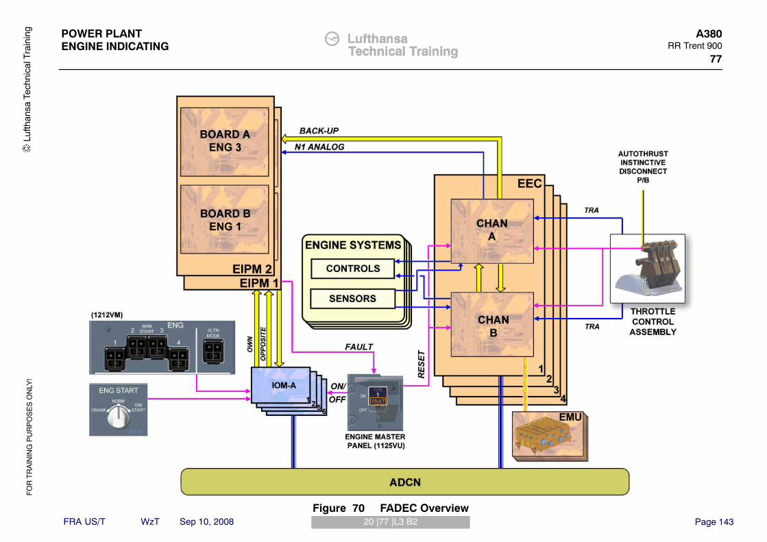
FO
R T
RA
ININ
G P
UR
PO
SE
S O
NLY
!
Page 14320 |77 |L3 B2
POWER PLANTENGINE INDICATING
A380RR Trent 900
77
FRA US/T WzT Sep 10, 2008
Lufth
ansa
Tec
hnic
al T
rain
ing
Figure 70 FADEC Overview

FO
R T
RA
ININ
G P
UR
PO
SE
S O
NLY
!
Page 14421 |77 |L3 B2
POWER PLANTENGINE INDICATING
A380RR Trent 900
77
FRA US/T WzT Sep 10, 2008
EEC Aircraft InterfacesEEC has digital interfaces, analog and discrete inputs/outputs.
EEC Digital InterfacesThe four EECs have digital interfaces with the aircraft systems through theADCN.The IOMs transmit cockpit commands (Master Lever, Rotary Selector, N1 P/B,Man Start P/B) and the EIPM and the AICU (Anti−Ice Control Unit) data to theEEC.The EIPMs receive, via the IOM, engine status data (speed, starting,shutdown, reverse inhibition, reverse locked...) from the EEC own and oppositedata busses.The AICU (Anti−Icing Control Unit) receives, via the IOM, data on enginerunning, maximum take off/go around, flex take off and derated take off limitmode selected. It sends WAI/NAI (Wing Anti−Ice/Nacelle Anti−Ice) status tothe EEC for engine thrust modulation.The EBAS (Engine Bleed Air System), the PADS (Pneumatic Air DistributionSystem) and the OHDS (Overheat Detection System) are hosted in CPIOM−A.Those systems receive data from the EEC concerning:� Engine status (engine starting and running, reverse operation) and starting
information for Pack closure,� Engine pressure & temperatures (P0, P30, T30),� Starter control valve position,� Burst duct detection (to OHDS).
The EBAS, the PADS and the OHDS send data to the EEC concerning:� Bleed configuration status,� HP/IP Command,� Bleed manifold Pressure,� Cross−bleed valves position,� APU isolation valve.
The AVS (Avionics Ventilation System), the AGS (Air Generation System) andthe CPCS (Cabin Pressure Control System) are hosted in CPIOM−B. The AVSreceives data from the EEC concerning the Engine Status (engine running/ notrunning). The CPCS receives data from the EEC concerning the Enginerunning, the engine take−off power and the N1 speed. The AGS receives
engine starting information for the closure demand of the pack valves from theEEC.The FWS (Flight Warning System) is hosted in CPIOM−C: It receives enginefailures warning annunciation and engine status (speed, starting, shutdown,reverse operation) from the EEC via the ADCN and from EIPM in back up withARINC 429 bus.The WBBC (Weight and Balance Back−up Computer), hosted in CPIOM−C,receives data on fuel used from the EEC.The ATC (Air traffic Control) is hosted in CPIOM−D1 and receives data fromthe EEC on engine status (engine running, not running...).The FQMS (Fuel Quantity Management System) is hosted in CPIOM−F: Itreceives Fuel used data from the EEC and sends fuel temperature data to theEEC.The LGERS (Landing Gear Extension Retraction System) is hosted inCPIOM−G: It sends wing and body landing gears status (for flight/groundstatus computation) to the EEC.The DSMS (Doors and Slides Management System) receives engine runningdata from the EEC.The EPGS (Electrical Power Generating System) receives data from the EECon the engine status (MASTER lever OFF, engine Start/crank sequence active)and on engine speeds N3.The PRIM (Flight controls and Guidance Computer) receives Engine status(speed, starting, shutdown, reverse operation) and autothrust feedbacks(actual thrust, commanded thrust, thrust limits...) from the EEC. It sends to theEEC:� Autothrust command,� Autothrust engaged and active signals,� Alpha floor protection,� Throttle position (for consolidation of EEC signals),� T/O mode selection input (Flex temperature, derated T/O levels, Derated
Climb levels),� TCM (Thrust Control Malfunction) permission discrete command,� Wheel speed (provision).
Lufth
ansa
Tec
hnic
al T
rain
ing

FO
R T
RA
ININ
G P
UR
PO
SE
S O
NLY
!
Page 14521 |77 |L3 B2
POWER PLANTENGINE INDICATING
A380RR Trent 900
77
FRA US/T WzT Sep 10, 2008
Lufth
ansa
Tec
hnic
al T
rain
ing
Figure 71 EEC Digital Interfaces 1

FO
R T
RA
ININ
G P
UR
PO
SE
S O
NLY
!
Page 14621 |77 |L3 B2
POWER PLANTENGINE INDICATING
A380RR Trent 900
77
FRA US/T WzT Sep 10, 2008
The AESS (Aircraft Environment Surveillance System) receives Enginerunning, selected take off power and thrust data from the EEC.The ADIRS (Air data and Inertial reference System) receives engine runningdata and engine Ps, Pt, TAT (for consolidation of ADIRU internal parameters)data from the EEC. The ADIRS sends air data parameters (Ps, Pt, TAT, M),probe heat status (pitot, L/H static, TAT, AOA), and CAS (calibrated airspeed)to the EEC. The ECB (APU controller) receives start sequence signal for theAPU boost from the EEC and sends APU availability signal (for bleedconfiguration determination) to the EEC.The SFCC (Slat/Flap Control Computer) sends slat/flap configuration (forapproach selection) to the EEC.The CDS (Command and Display System) receives from the EEC:� Engine Primary parameters (THR, N1, EGT),� Engine secondary parameters (N2, N3, FF (Fuel Flow), Fuel Used, Oil
Quantity, Oil Temperature, Oil Pressure, Vibration levels),� Engine status (speed, starting, shutdown, reverse operation).
The ACMS (Aircraft Condition Monitoring System) and the FDIAF (Flight Dataand Interface/Acquisition Function) are hosted in the CDAM (Centralized DataAcquisition Module). Those systems receive engine data for performance andtrend monitoring, engine manufacturer’s reserved parameters, and EMUadvanced Maintenance reports.The FDRS (Flight data Recording System), linked on the CDAM, receives datafrom the EEC concerning:� PS3, Regulated Pressure, Engine bleed demand/K factors,� N1/TPR limit, N2, N3,� Each thrust reverser position, and throttle / power lever position,� EGT, oil quantity, Engine Vibration, oil temperature, and oil pressure,� HP/LP fuel valve,� Fuel flow, and derated take−off,� Position engine relight indication,� Thrust command,� Engine warning (each engine vibration),� Thrust/Power on each engine.
The CDAM transmits its data to the OMS (Onboard Maintenance System).The OMS application interfaces with ADCN through the SCI (SecureCommunication Interface) data.
Lufth
ansa
Tec
hnic
al T
rain
ing

FO
R T
RA
ININ
G P
UR
PO
SE
S O
NLY
!
Page 14721 |77 |L3 B2
POWER PLANTENGINE INDICATING
A380RR Trent 900
77
FRA US/T WzT Sep 10, 2008
Lufth
ansa
Tec
hnic
al T
rain
ing
Figure 72 EEC Digital Interfaces 2

FO
R T
RA
ININ
G P
UR
PO
SE
S O
NLY
!
Page 14822 |73 |L3 B2
POWER PLANTENGINE FUEL & CONTROL
A380RR Trent 900
73
FRA US/T WzT Sep 10, 2008
ATA 73 ENGINE FUEL & CONTROL
EEC ANALOG AND DISCRETE INPUTS/OUTPUTS
The EEC has direct interfaces with aircraft systems and cockpit controls. Itreceives and sends analog and discrete data.Control of the engines is achieved by modulation of a throttle lever angle.The TCA (Throttle Control Assembly) receives the excitation current for theresolvers from each channel of the EEC.The TRA (Throttle Resolver Angle) of the throttle lever position is transmitted inanalog signals to each channel of the EEC.A discrete signal from the MASTER lever is directly hardwired to each channelof the EEC, for EEC reset function.The activation of the A/THR instinctive disconnect P/B is used to disengage theA/THR mode on all engines. An A/THR instinctive disconnect discrete signal isdirectly hardwired to one EEC channel (internally cross−wired) as well as to theFlight Controls Computers (PRIMs) and to the Flight Warning System.In order for the Engine Control System to protect against TCM (Thrust ControlMalfunction), an independant discrete signal from the aircraft is directlyhardwired to each EEC. The purpose of this independant input is to authorisethe EEC to shut the engine down if it has detected an uncommanded anduncontrollable thrust excursion, which may affect the aircraft controllability. TheTCM protection signal is set by the Flight Controls PRIM (PRIMary Computer).Each EEC receives from the Airframe hardwired discretes indicating positionon the aircraft. These discretes are directly hardwired from the Pylon jonctionbox to the EEC.A N1 speed back−up signal will be made available at the aircraft level. Theanalog signal is wired directly from the N1 sensor on the engine to the EIPMcomputer. The N1 back−up indication is used to keep as a minimum the N1display available under the following cases:� AFDX network failure,� Complete loss of EEC,� Complete loss of AFDX busses on the engine.
When engine speed is detected to be higher than 50% N3 (for Trent 900Engine), both EEC channels set the engine running discrete output.
However, only the output from the channel A is planned to be acquired on theaircraft side by the IOMs 1 and 2, the Emergency Power Center, the PEPDC(Primary Electrical Power Distribution Center) and the HSMU (HydraulicSystem Monitoring Unit).For engine in−flight wind milling restart purposes, the EEC has the possibility todepressurize both hydraulic pumps on the engine. To achieve this function,both EEC channels are able to switch one output ground/open discrete signalthat commands the depressurization of both engine−driven hydraulic pumps.
Lufth
ansa
Tec
hnic
al T
rain
ing

FO
R T
RA
ININ
G P
UR
PO
SE
S O
NLY
!
Page 14922 |73 |L3 B2
POWER PLANTENGINE FUEL & CONTROL
A380RR Trent 900
73
FRA US/T WzT Sep 10, 2008
Lufth
ansa
Tec
hnic
al T
rain
ing
Figure 73 EEC Analog and Discrete Inputs/Outputs

FO
R T
RA
ININ
G P
UR
PO
SE
S O
NLY
!
Page 15023 |73 |L3 B2
POWER PLANTENGINE FUEL & CONTROL
A380RR Trent 900
73
FRA US/T WzT Sep 10, 2008
EEC COMMAND AND SENSOR INTERFACES
The FADEC has to perform engine control and monitoring.The DEP (Data Entry Plug) is a dual channel serial memory device providingstorage for engine specific performance and configuration information. TheDEP is a plug and housing, which is fastened to the engine by the use of alanyard. The data entry plug is only programmed with the applicable data forthe engine on which it is installed. It cannot be removed and then installed to adifferent engine unless it is programmed for that engine.The data entry plug is programmed with the data that follows:� Turbofan power ratio trim,� Engine rating selection,� EGT trim,� Engine serial number,� Idle trim.
Note: If the DEP and the engine do not have the same data the engine will notoperate normally.The fuel flow XMTR (Transmitter) continuously monitors the fuel flow to thecombustion system. The XMTR supplies analog signals to the EEC that are inproportion to the mass fuel flow rate. The EEC uses these signals to calculatethe flow rate and the quantity of fuel that has been used. The EEC thentransmits this data for display in the cockpit.The Fuel filter differential pressure switch indicates to the EEC if the fuel filter iscoming clogged.The oil quantity XMTR is installed through an opening in the center of the topface of the oil tank. The EEC uses this signal for display in the cockpit.The oil pressure XMTR senses the difference between supply and scavenge oilpressures. One XMTR per each channel of the EEC supplies an oil pressureindication.The oil temperature thermocouples are installed at the top of the scavenge oilfilter housing. The system uses the thermocouples that are sensitive totemperature changes. An oil temperature signal is sent through the EEC to theaircraft indicating system.The filters differential pressure switches (supply and scavenge) compare thedifference between upstream and downstream pressure for their related filters.
Dual vibration XDCR (Transducer) signal and magnetic chip detector signal arecomputed by EMU, which monitors engines performance and trend, enginesvibration.Both channels of the EEC have a T20 thermocouple analog input. The T25thermocouple sends, to the EEC, the signal of the TAT (Total Air Temperature)at the IP compressor exit. This signal is used for health monitoring purposes.The signal is input to both channels of the EEC.The T30 signal is obtained by two single element thermocouples mounted atdifferent radial positions around the engine. Each thermocouple sends a signalto the related channel of the EEC. T30 is the TAT at the HP compressor.The EGT (Exhaust Gas Temperature), or TGT (Turbine Gas Temperature) isderived from 14 double element thermocouples mounted in the nozzle guidevanes. The thermocouples are wired in parallel by two leads, one in alumel andone in chromel. Each pair of leads is connected to each channel of the EEC.The TCAF (Turbine Cooling Air Front) probe converts the IP turbinedisc−cooling air temperature at the front of the disc into an electrical signal.The TCAR (Turbine Cooling Air Rear) probe converts the IP turbinedisc−cooling air temperature at the rear of the disc into an electrical signal.TCAF and TCAR thermocouples are used to provide IP Turbine disk overheatdetection.A single thermocouple, mounted on the IP/LP TCC flange, sends to the EEC atemperature signal from Zone 3 nacelle, used for condition monitoringpurposes.The N1C and N1T shaft speeds are derived from engine pulse probes.The probes provide a sinusoidal frequency voltage proportional to the LPcompressor and LP turbine shaft speed rotation. The N1 Compressor speedsignal is sent to each channel of the EEC, as a main parameter for thrustlimitation and N1 mode back−up computation. The comparison between N1Cand N1T speeds is used to give a LP Turbine overspeed protection.The N2 shaft speed signal is derived from engine pulse probes. The probessupply a sinusoidal fraquency voltage proportional to the IP shaft speedrotation. The N2 speed signals are used for engine control functions and areused by the ROS (Rotor OverSpeed) protection. The N2 speed signal is sent toeach channel of the EEC.
Lufth
ansa
Tec
hnic
al T
rain
ing

FO
R T
RA
ININ
G P
UR
PO
SE
S O
NLY
!
Page 15123 |73 |L3 B2
POWER PLANTENGINE FUEL & CONTROL
A380RR Trent 900
73
FRA US/T WzT Sep 10, 2008
Lufth
ansa
Tec
hnic
al T
rain
ing
Figure 74 EEC Command and Sensor Interfaces 1

FO
R T
RA
ININ
G P
UR
PO
SE
S O
NLY
!
Page 15223 |73 |L3 B2
POWER PLANTENGINE FUEL & CONTROL
A380RR Trent 900
73
FRA US/T WzT Sep 10, 2008
The N3 shaft speed signal, used within the EEC, is derived from the PMA(Permanent Magnetic Alternator). The outputs from the PMA are at afrequency proportional to the N3 shaft speed and send an N3 speed signal toeach channel of the EEC.The P0 signal is input to channel B.The P20 probe sends to the EEC, the signal of the TAT (Total Air Temperature)at the engine air intake. The EEC automatically selects the P20 probe heater toprevent ice on the probe air inlets. The P20 signal is input to channel B.The HP compressor pressure signal called P30 is split inside the EEC to give apressure tapping to a transducer in each channel. The ratio P30/P20 is usedfor the TPR thrust computation.The IP Compressor pressure signal called P25 is input to the EMU forcondition monitoring purposes.The P50 signal is an exhaust gas pressure signal, which is split into the EMUto give a pressure tapping to a transducer in each channel of the EEC.A fan exit signal called P160 is used for condition monitoring purposes and isinput to the EMU.The EEC controls the starting system during the engine start sequence, theEEC opens the starter control valve to operate pneumatic starter from eitherAPU air, cross−bleed air or an external air source. The EEC receives feedbackfrom the starter control valve position switch.The EEC supplies the two ignition units (A and B) of the Ignition system with115 VAC aircraft power.The EEC controls the fuel flow to the combustion system. The control elementsare:� The Metering valve, which controls the rate of fuel flow (the EEC receives
feedback from an LVDT),� The PROT MOTOR, which has three positions (STBY, TCM, OVSP),� The MPSOV, which can stop the flow and cause an engine shutdown in
case of an overspeed (the feedback is given by the MPSOV switch)� The VSV controller, which supplies fuel to the VSV actuators (the EEC
receives feedback from a LVDT located on the VSV actuators).
In the engine air system, the EEC controls the operation of eight valves:� Three IP 8 bleed valves,� Three HP 3 bleed valves,� The TCC (Turbine Case Cooling) valve.
To prevent an engine surge condition, bleed valves controlled by solenoids areindependently supplied with electrical power from the EEC. During cruisecondition, the EEC fully opens the TCC valve to supply LP compressor air tothe external surface of the turbine cases. This causes a smaller clearancebetween the cases and the tips of the HP and IP/LP turbine blades to increaseturbine performance. There is no feedback of the bleed and the TCC valves.The EEC controls the ETRAC (Electronic Thrust Reverser Actuation Controller)through an ARINC 429 BUS. The Thrust Reverser Power Unit sends aninhibition signal to the EEC through the ETRAC. The EEC receives feedbackfrom the TLS (Tertiary Locking System) proximity SNSRs, from the RH and LHside proximity SNSRs and from the RH and LH side cowl resolvers.The EEC controls the hydraulic pump off−load solenoids (channel A for EDP1and channel B for EDP2) to depressurize the hydraulic system during anin−flight start.The EEC receives feedback from the engine anti−ice protection system forbleed status demand.The EEC channel B only monitors the RAIV (Regulated Anti Ice Valve) positionby means of a High Pressure Switch.
Lufth
ansa
Tec
hnic
al T
rain
ing

FO
R T
RA
ININ
G P
UR
PO
SE
S O
NLY
!
Page 15323 |73 |L3 B2
POWER PLANTENGINE FUEL & CONTROL
A380RR Trent 900
73
FRA US/T WzT Sep 10, 2008
Lufth
ansa
Tec
hnic
al T
rain
ing
Figure 75 EEC Command and Sensor Interfaces 2

FO
R T
RA
ININ
G P
UR
PO
SE
S O
NLY
!
Page 15424 |73 |L3 B2
POWER PLANTENGINE FUEL & CONTROL
A380RR Trent 900
73
FRA US/T WzT Sep 10, 2008
EIPM ARCHITECTURE & INTERFACE DESCRIPTION
ArchitectureThere are two EIPMs (Engine Interface Power Management Units) per aircraft,one unit per two engines with dedicated and separated boards and processorper engine.EIPM1:� Board A: ENG 2� Board B: ENG 4
EIPM2:� Board A: ENG 3� Board B: ENG 1
The EIPM, installed in the avionics bay, controls and delivers electrical powersupply from aircraft towards engine systems.The basic function of the EIPM is to control and monitor the electrical powersupply to:� EEC (Engine Electronic Controller),� COS (Cowl Opening System) via the PCPU (Primary COS Power Unit),� P20T20,� ETRAC (Electronic Thrust Reverser Actuation Controller),� EMU (Engine Monitoring Unit),� Ignitors.
The EIPM converts N1 analog signal in ARINC 429 bus, for back−up.From a DSI (Discrete Signals Input) group the EIPM generates, for aircraftinterface purpose, DSO (Discrete Signals Output) group.
The EIPM exchanges also data via ARINC 429 with:� The OMS (Onboard Maintenance System) through the SCI (Secure
Communication Interface). The OMS and the SCI are in the NSS (NetworkServer System),
� The CDS (Control and Display System) via the CPIOM (Core ProcessingInput Output Module) of the FWS (Flight Warning System) as a back−upoutput,
� The IOM (Input Output Module),� The EEC Channel A (back−up),� The SSPCs (Solid State Power Controllers) in the SEPDC (Secondary
Electrical Power Distribution Center) via the IOM and the ADCN (AircraftData Communication Network).
Lufth
ansa
Tec
hnic
al T
rain
ing

FO
R T
RA
ININ
G P
UR
PO
SE
S O
NLY
!
Page 15524 |73 |L3 B2
POWER PLANTENGINE FUEL & CONTROL
A380RR Trent 900
73
FRA US/T WzT Sep 10, 2008
Lufth
ansa
Tec
hnic
al T
rain
ing
Figure 76 EIPM Architecture

FO
R T
RA
ININ
G P
UR
PO
SE
S O
NLY
!
Page 15625 |73 |L3 B2
POWER PLANTENGINE FUEL & CONTROL
A380RR Trent 900
73
FRA US/T WzT Sep 10, 2008
EIPM INTERFACES
Electrical Power Supply Control LogicsEach electrical power supply AC2 BUS (EEC, Igniters, ETRAC, P20T20,EIPM) is controlled by SSPCs.In case of EIPM failure or loss, the EEC channels are fail−safe power supplied.In the EIPM each power supply is controlled by relays, which are controlled bythe electrical power supply control logics.
Interface Control LogicsThe EIPM proceeds to the control and monitoring of the DSI and DSO groups.The EIPM computes the ”oil low press and ground” signal based on theacquisition and combination of discrete signals from the LGRDCs (LandingGear Remote Data Concentrator) and Oil Low Press switch, and ARINC signalfrom IOM (SCI, EEC).The EIPMU sends (via discrete signal) the ”oil low press and ground” signal toother users (IOM, CIDS (Cabin Intercommunication Data System), FCDC(Flight Control Data Concentrator)).The EIPM controls the second line of defense of the Thrust Reverser system,only according to states of inputs of the LGRDC status, reverse switch position,and ARINC bus. This second line of defense is authorized via discrete outputRCCB (Remote Control Circuit Breaker) command.The EIPM monitors the T/R second defense line authorization via the RCCBmonitoring input.The RCCB Command function is only available for engine 2 and engine 3(inboard engine).The EIPM controls the power supply of the Cowl Opening System. The fan andThrust Reverser (or Fan Exhaust) cowl opening is done via the PCPUsupplying electrical actuators.The power supply of the COS is only available when the aircraft is on groundand with engine not running.EIPM also uses ARINC data to manage COS application.By default, manual cowls opening is inhibited and carried out by the function ofCOS.The power supply to the COS is cut in case of action on the ”handfulfire−break” of the associated engine.
When the FADEC (Full Authority Digital Engine Control) ground power P/B isactivated, the EIPMU electrically powers the EEC channels for five minutes(maintenance only) if no OMS interactive mode.If the ENG FIRE P/B SW is activated, the EIPM cuts−off the electrical powersupply to EEC channels for isolation purpose.The EEC sends the MASTER lever FAULT light (Boolean information) to theEIPM. The EIPM generates a power supply discrete signals to turn the EngineFAULT light on, on the Master Lever.The EIPM acquires N1 speed in an analog form and transmits it via ARINC 429to the IOM and the FWC. This information is used as a back up information ofthe N1 speed from the EEC via the ADCN.
Lufth
ansa
Tec
hnic
al T
rain
ing

FO
R T
RA
ININ
G P
UR
PO
SE
S O
NLY
!
Page 15725 |73 |L3 B2
POWER PLANTENGINE FUEL & CONTROL
A380RR Trent 900
73
FRA US/T WzT Sep 10, 2008
Lufth
ansa
Tec
hnic
al T
rain
ing
Figure 77 EIPM Interfaces

FO
R T
RA
ININ
G P
UR
PO
SE
S O
NLY
!
Page 15826 |73 |L3 B2
POWER PLANTENGINE FUEL & CONTROL
A380RR Trent 900
73
FRA US/T WzT Sep 10, 2008
EIPM & FADEC POWER SUPPLY DESCRIPTION
GeneralThe FADEC (Full Authority Digital Engine Control) has two computers:� EEC (Engine Electronic Controller),� Engine Monitoring Unit (EMU).
The power supply of the EEC can be processed into two different manners:� By the airframe power supply (115 VAC) that comes from the EIPM (Engine
Interface Power Management),� By the EEC dedicated alternator, also called PMA (Permanent Magnet
Alternator).EEC is normally powered by its own power supply (PMA), when engine isrunning.EMU is supplied by airframe power supply (115 VAC)
WARNING: DO NOT SET THE MASTER LEVER TO THE ”ON” POSITIONWITH THE ENGINE ROTARY SELECTOR ALREADY IN THE”IGN/START” OR ”CRANK” POSITION. ENGINE RISKS TO BESTARTED OR CRANKED
Airframe Power SupplyEIPM is powered in 28 VDC DC1 BUS.The EEC receives power from two airframe 115VAC buses through the EIPMcontrol logic function.The supply line from the emergency bus is connected into channel A of theEEC and the line from the Airframe AC2 bus is connected with channel B of theEEC. In an emergency situation (following loss of all variable frequencygenerators), only the emergency bus from airframe will operate.The airframe power supply is available on ground and in flight and shall beused by the EEC for its ground tests, ground engine starting, and in flightstarting when engine speed is below 8% N3, or in case of PMA failure.
EEC Dedicated Alternator Power Supply (PMA)The PMA has a Stator and Rotor that supply two independent three−phasepower windings to the EEC (1 per channel). A mechanical drive from theEngine gearbox is used to rotate the PMA Rotor. The interface is required topower the EEC in all Engine running conditions.
When the engine speed is above 8% N3, the PMA will deliver the electricalpower necessary for the EEC to achieve its functions including in−flight starterassist or wind−milling engine starting.
NOTE: Between 5% and 8% of N3 the power supply to the EEC isshared between airframe power and PMA power.
NOTE: one single phase is also dedicated to N3 sensing.
FADEC Power Supply
Aircraft Power−UpAt aircraft Power−up or EIPM initialization, the EEC and the EMU will bepowered as detailed below:Channel A will be powered if with the airframe 115 VAC Emergency bus isavailable,Channel A & B and the EMU will be powered for 5 minutes if the full airframeelectrical network is available.
Engine Mode SelectorWith engine not running:� When you set the ENG START rotary selector to ”CRANK” or ”STAR/IGN”
position, the EEC and the EMU are permanently supplied,� When you set the ENG START rotary selector to the ”NORM” position the
power supply of the EECs and the EMU is cut off
Engine Master LeverWith engine not running:� Each ENG MASTER lever in the ”ON” position supplies permanently the
related EEC and EMU.On the ground, airframe 115 VAC will be removed from the EEC and EMU 15minutes after selection of the ENG MASTER lever from the ”ON” to ”OFF”position. This will not occur in flight.
Lufth
ansa
Tec
hnic
al T
rain
ing

FO
R T
RA
ININ
G P
UR
PO
SE
S O
NLY
!
Page 15926 |73 |L3 B2
POWER PLANTENGINE FUEL & CONTROL
A380RR Trent 900
73
FRA US/T WzT Sep 10, 2008
Lufth
ansa
Tec
hnic
al T
rain
ing
Figure 78 EIPM & FADEC Power Supply 1

FO
R T
RA
ININ
G P
UR
PO
SE
S O
NLY
!
Page 16026 |73 |L3 B2
POWER PLANTENGINE FUEL & CONTROL
A380RR Trent 900
73
FRA US/T WzT Sep 10, 2008
Engine FADEC Ground PowerFor maintenance operation, with the ENG FADEC GrouND PoWeR P/Bselected to the ”ON” position and the EEC interactive mode not instigated,airframe 115 VAC will be cut off for 10 minutes.The airframe 115 VAC power will be cut off immediately by selecting the ENGFADEC GrouND PoWeR P/B to the ”OFF” position or by returning the ENGrotary selector to the ”NORM” position (with the ENG MASTER lever to the”OFF” position).
Engine Fire Push−ButtonIn the case of fire, in flight or on ground, airframe 115 VAC power will be cut offimmediately following operation of the ENGine FIRE P/B SW.
EIPM−FailureIn the event of EIPM failure, airframe 115 VAC power will be permanentlyavailable to the EEC whenever the airframe electrical network is powered.
EEC Dedicated Alternator FailureIf the EEC dedicated alternator winding for the EEC channel in controlbecomes defective, there will be an EEC channel change over if the secondwinding is healthy.If both alternators power supply is lost, the EEC will be supplied by the airframe115 VAC through the EIPM.
Lufth
ansa
Tec
hnic
al T
rain
ing

FO
R T
RA
ININ
G P
UR
PO
SE
S O
NLY
!
Page 16126 |73 |L3 B2
POWER PLANTENGINE FUEL & CONTROL
A380RR Trent 900
73
FRA US/T WzT Sep 10, 2008
Lufth
ansa
Tec
hnic
al T
rain
ing
Figure 79 EIPM & FADEC Power Supply 2

FO
R T
RA
ININ
G P
UR
PO
SE
S O
NLY
!
Page 16227 |73 |L3 B2
POWER PLANTENGINE FUEL & CONTROL
A380RR Trent 900
73
FRA US/T WzT Sep 10, 2008
FADEC TEST
TestsThe OMS (Onboard Maintenance System) is used for the test of two maincomputers of the power plant system:� EEC (Engine Electronic Controller)� EIPM (Engine Interface Power Management)
These tests are launched from the OMS HMI (Human−Machine Interface)using the OMT (Onboard Maintenance Terminal), OIT (Onboard InformationTerminal) or GMAT (Ground Maintenance Access Terminal).
EECTo reach the ”TEST SELECTION” page, you must select the ATA and thesystem to test in the ”ATA SELECTION” page. Then you select the channel inthe ”SIDE SELECTION”.The EEC gives the following interactive tests, reports, engine procedures,specific functions:
Lufth
ansa
Tec
hnic
al T
rain
ing

FO
R T
RA
ININ
G P
UR
PO
SE
S O
NLY
!
Page 16327 |73 |L3 B2
POWER PLANTENGINE FUEL & CONTROL
A380RR Trent 900
73
FRA US/T WzT Sep 10, 2008
Lufth
ansa
Tec
hnic
al T
rain
ing
Figure 80 Tests − EEC

FO
R T
RA
ININ
G P
UR
PO
SE
S O
NLY
!
Page 16428 |73 |L3 B2
POWER PLANTENGINE FUEL & CONTROL
A380RR Trent 900
73
FRA US/T WzT Sep 10, 2008
TestsAUDIBLE TEST OF THE IGNITERSThe EEC cannot detect the operation of the igniter during the test.Even if the test is OK, the result is indicated; you have to make sure that youhear sparks from the ignition system on the engine.VARIABLE−STATOR−VANES SYSTEM TESTThe engine will be dry cranked during the test.
CAUTION: YOU SET THE CONTROLS AS SPECIFIED IN THEPROCEDURE DISPLAYED ON THE OMS, THE DRY CRANKWILL START IMMEDIATELY.
TEST OF THE P20T20 PROBE HEATER
CAUTION: THE P20T20 PROBE WILL BE ENERGIZED FOR 5 SECONDSAND BECOMES HOT DURING THIS TEST.
Make sure that not cover, cap or plug is installed on the P20T20 probe.HYDRAULIC PUMP OFFLOAD TESTThe engine will be dry cranked during the test.
CAUTION: YOU SET THE CONTROLS AS SPECIFIED IN THEPROCEDURE DISPLAYED ON THE OMS, THE DRY CRANKWILL START IMMEDIATELY. IN THIS TEST YOU MUST LOOKTO SEE IF THE HYDRAULIC PRESSURE INCREASES ANDDECREASES AT THE APPLICABLE TIMES.
HARNESS TESTThis test monitors the Full Authority Digital Engine Control (FADEC) system for15 minutes and looks for faults while you shake the harness.THRUST REVERSER CYCLING TEST
NOTE: This test is only done onto the EEC of the inboard engines.
WARNING: THRUST REVERSER WILL BE ENERGIZED AND MOVEDDURING TEST. MAKE SURE THAT THE THRUST REVERSERAREA IS CLEAR AND CLEAN OF PERSONS AND TOOLS OROTHER ITEMS.
Make sure that the thrust reverser is not in the inhibited position. Move thethrottle lever to reverse idle within 50 seconds, then move the throttle lever toforward idle within 50 seconds.
ReportsThe reports are the same for the two channels of the four EEC.EGT EXCEEDANCE REPORTSHAFT−SPEEDTHE STATUS OF AIRCRAFT HARDWIRED INPUTS
Engine ProceduresThe engine procedures are the same for the two channels of the four EEC.FAN TRIM BALANCEENGINE CORE WASHINGBLEED−VALVE TEST SCHEDULING
CAUTION: THE ENGINE MUST BE STARTED TO PROVIDE THE AIRPRESSURE TO OPERATE THE BLEED VALVES WHENCOMMANDED BY EEC
Specific FunctionsThe specific functions are the same for the two channels of the four EEC.ENGINE RUNNING SIMULATIONEngine run discrete signal simulation. The engine is not started for this testRESET FUEL USED
Lufth
ansa
Tec
hnic
al T
rain
ing

FO
R T
RA
ININ
G P
UR
PO
SE
S O
NLY
!
Page 16528 |73 |L3 B2
POWER PLANTENGINE FUEL & CONTROL
A380RR Trent 900
73
FRA US/T WzT Sep 10, 2008
Lufth
ansa
Tec
hnic
al T
rain
ing
Figure 81 EEC Tests and Specific Functions

FO
R T
RA
ININ
G P
UR
PO
SE
S O
NLY
!
Page 16629 |73 |L3 B2
POWER PLANTENGINE FUEL & CONTROL
A380RR Trent 900
73
FRA US/T WzT Sep 10, 2008
EIPMTo reach the ”TEST SELECTION” page, you must select the ATA and thesystem to test in the ”ATA SELECTION” page. Then you select the channeldedicated to an engine in the ”SIDE SELECTION” page.The EIPM gives the following interactive tests, reports and Specific function:
TestsThe tests are the same for each EIPMGROUND POWER LIGHTENGINE LIGHT FAULT
ReportsThe reports are the same for each EIPMDISCRETE INPUTS REPORTSDISCRETE OUTPUTS REPORTSPIN PROGRAMMING REPORTS
Specific FunctionOIL LOW PRESS AND GROUNDOn the EIPM 1 ENG 2 and the EIPM 2 ENG 3 there are two other specificfunctions:THRUST REVERSER 3*115 V / 25 KW POWER SUPPLY
WARNING: REVERSE SECOND LINE OF DEFENSE WILL BEDEACTIVATED; POSSIBLE REVERSE DOORS ACTIVATIONCAN OCCUR.
ETRAC MANUAL POWER SUPPLY
WARNING: ELECTRONIC THRUST REVERSER ACTUATIONCONTROLLER (ETRAC) WILL BE POWER SUPPLIED;POSSIBLE REVERSE DOORS ACTIVATION CAN OCCUR.
Lufth
ansa
Tec
hnic
al T
rain
ing

FO
R T
RA
ININ
G P
UR
PO
SE
S O
NLY
!
Page 16729 |73 |L3 B2
POWER PLANTENGINE FUEL & CONTROL
A380RR Trent 900
73
FRA US/T WzT Sep 10, 2008
Lufth
ansa
Tec
hnic
al T
rain
ing
Figure 82 EIPM Tests and Specific Function

FO
R T
RA
ININ
G P
UR
PO
SE
S O
NLY
!
Page 16830 |73 |L3
POWER PLANTENGINE FUEL AND CONTROL
A380
73
FRA US/T WzT Sep 10, 2008
FUEL SYSTEM INTRODUCTION
The function of the system is to receive fuel from the Aircraft tanks and deliverconditioned metered fuel into the combustion chamber for combustion.The fuel system is divided into:� Fuel Control� Fuel Supply
Low Pressure Pump (LPP)The LPP is a single stage centrifugal pump that receives fuel from the Aircraftsystem and ensures satisfactory pressure to both HP pump inlets.
Fuel Oil Heat Exchanger (FOHE)The heat exchanger is used to transfer heat between the engine oil and the LPfuel from the LPP.
LP Fuel FilterThe filter removes contaminants from the LP fuel before it passes to the HPsystem. It is a 40 micron non−cleanable filter.A differential pressure transducer (set at 5psid) provides an indication ofimpending filter blockage. A by−pass valve operates at 25 psid to allowunfiltered fuel to the HP pump.
Main High Pressure Pump (HPP)The HP pump is a spur gear type pump and provides high pressure fuel to theHMU.
Servo High Pressure Pump (HPP)The Servo HP pump is a spur gear type pump and provides high pressure fuelto the HMU for use in the Variable Stator Vane (VSV) system.
Hydromechanical Unit (HMU)The HMU interfaces with the EEC to control fuel flow for all normal &emergency conditions through the fuel metering, overspeed and fuel shut−offvalves. The shut−off valve can also be operated by electrical signals from thefuel control switch in the cockpit
Fuel Flow TransmitterThe transmitter provides a signal of fuel flow to the EEC for onwardtransmission to the cockpit for display.
HP Fuel FilterLocated in the inlet to the fuel manifold to prevent blockage of the fuel spraynozzles. The HP fuel filter is a cleanable 250 micron filter
Fuel Manifold & Fuel Spray Nozzles (FSN)The fuel manifold is an assembly of flexible hoses at equal distances aroundthe combustion outer case. The manifold distributes the fuel to the 20 FSNsthat provide the necessary atomisation of fuel into the combustion chamber.
Lufth
ansa
Tec
hnic
al T
rain
ing

FO
R T
RA
ININ
G P
UR
PO
SE
S O
NLY
!
Page 16930 |73 |L3
POWER PLANTENGINE FUEL AND CONTROL
A380
73
FRA US/T WzT Sep 10, 2008
Lufth
ansa
Tec
hnic
al T
rain
ing
Figure 83 Fuel System Schematic

FO
R T
RA
ININ
G P
UR
PO
SE
S O
NLY
!
Page 17031 |73 |L3
POWER PLANTENGINE FUEL AND CONTROL
A380
73
FRA US/T WzT Sep 10, 2008
FUEL SYSTEM SCHEMATIC & CONTROL
Direct Control InputsThe engine master switch outputs to the following:� ON/OFF command directly to the LP Shutoff Valve� ON/OFF command to the IOM‘s� OFF command only to the airframe shutdown solenoid in the HMU.
The master switch input to the IOM is sent to both channels of the EEC via theADCN.The throttle resolvers input the throttle position to each channel of the EEC.The auto thrust system also inputs thrust requirements to the EEC when autothrust is selected.The PRIMs also input to the EEC to provide a discrete signal when parametersallow engine shutdown, during a thrust control malfunction (TCM).Control OutputsThe EEC controls the engine fuel system through the HMU using the followingdevices:� Metering valve servo valve� Protection Torque Motor� VSV Controller
Fuel System Inputs to the EECThe HMU has the following feedback devices:� An LVDT which provides positional feedback to the EEC of metering valve
position� A dual proximity probe providing Minimum Pressure Shut Off valve
(MPSOV) position to the EEC.A differential pressure (dP) transducer provides an indication of partialblockage of the LP fuel filter.The Fuel Flow Transmitter provides a mass flow indication to the EEC.
Lufth
ansa
Tec
hnic
al T
rain
ing

FO
R T
RA
ININ
G P
UR
PO
SE
S O
NLY
!
Page 17131 |73 |L3
POWER PLANTENGINE FUEL AND CONTROL
A380
73
FRA US/T WzT Sep 10, 2008
Lufth
ansa
Tec
hnic
al T
rain
ing
Figure 84 Fuel System Schematic and Control

FO
R T
RA
ININ
G P
UR
PO
SE
S O
NLY
!
Page 17232 |73 |L3
POWER PLANTENGINE FUEL AND CONTROL
A380
73
FRA US/T WzT Sep 10, 2008
FUEL PUMP
PurposeThe fuel pump receives fuel from the Aircraft and pressurises it sufficiently toensure:� Adequate pressure for fuel powered actuators� Good atomisation of fuel at the FSNs
LocationThe low pressure fuel pump and the high pressure fuel pumps (2) arecombined as one single assembly mounted on the rear face of the externalgearbox
DescriptionFuel from the aircraft flows into the inlet of the centrifugal impeller type LPpump. The LP pump compresses any fuel vapour back into solution andincreases the fuel pressure by centrifugal action to approximately 175 psid (atmax speed). The LP fuel is supplied to the FOHE. The LP pump also suppliesfuel through a filter to the fuel drains tank ejector.There are two high−pressure fuel pumps (HPP) which are both positivedisplacement spur gear type pumps.The main HP pump increases the main fuel pressure to approximately 1725psid. (at maximum speed) and supplies fuel to the HMU for fuel delivery andcontrol.The servo HP pump increases the fuel pressure to approximately 1825 psid.(at maximum speed), and supplies fuel to the HMU for use by the VariableStator Vane (VSV) system.A full flow relief valve is fitted within the pump to prevent overpressurising thepump casing, which opens at 2250 psid. The relief valve returns HP fuel backto the HP pump inlet. There is also a relief valve on the servo pump, whichlimits maximum pressure to 2350 psid.The pump is driven from the external gearbox and is bolted to the rear face ofthe external gearbox.
Lufth
ansa
Tec
hnic
al T
rain
ing

FO
R T
RA
ININ
G P
UR
PO
SE
S O
NLY
!
Page 17332 |73 |L3
POWER PLANTENGINE FUEL AND CONTROL
A380
73
FRA US/T WzT Sep 10, 2008
Lufth
ansa
Tec
hnic
al T
rain
ing
Figure 85 Fuel Pump Assembly

FO
R T
RA
ININ
G P
UR
PO
SE
S O
NLY
!
Page 17433 |73 |L3
POWER PLANTENGINE FUEL AND CONTROL
A380
73
FRA US/T WzT Sep 10, 2008
FUEL OIL HEAT EXCHANGER (FOHE)
PurposeTo transfer heat from the engine oil to the fuel to prevent ice formation in thefuel.
LocationThe FOHE is mounted on the right side of the fan case below the oil tank.
DescriptionHeat is transferred from the oil to the fuel in the core of the FOHE. The oil flowis made slower by many baffle plates around the steel tubes through which thefuel is flowing. The slower oil flow enhances the exchange of heat between theoil and fuel.The LP fuel filter housing is part of the same LRU and fuel flows directly fromthe FOHE into the fuel filter.
LP FUEL FILTER
PurposeTo remove contaminants from the fuel before passing into the high−pressuresystem.
LocationAttached to the FOHE assembly and mounted on the right side of the fan case.
DescriptionThe LP fuel filter is a 40−micron non−cleanable element located in a cylindricalaluminium cast housing. The filter housing is connected by a bolted flangemidway along it is length, to the FOHE housing.The filter is held in place in the housing, sealed by a spring−loaded pressureplate reacting against the filter housing end cap that is bolted in position.In the event of a partial blockage of the filter, a differential pressure transducer(5 psid.) will provide a cockpit indication. If the filter becomes blocked, aby−pass valve opens at 25 psid to allow unfiltered fuel through to the HP pump.
Lufth
ansa
Tec
hnic
al T
rain
ing

FO
R T
RA
ININ
G P
UR
PO
SE
S O
NLY
!
Page 17533 |73 |L3
POWER PLANTENGINE FUEL AND CONTROL
A380
73
FRA US/T WzT Sep 10, 2008
Lufth
ansa
Tec
hnic
al T
rain
ing
Figure 86 Fuel / Oil Heat Exchanger (FOHE)

FO
R T
RA
ININ
G P
UR
PO
SE
S O
NLY
!
Page 17634 |73 |L3
POWER PLANTENGINE FUEL AND CONTROL
A380
73
FRA US/T WzT Sep 10, 2008
HYDROMECHANICAL UNIT (HMU)The HMU is installed on the rear face of the external gearbox. Fuel flowbetween the pump and HMU is via internal passages in the gearbox.
PurposeTo control the fuel flow to the fuel spray nozzles and combustion chamber fromelectrical inputs received from the following:� EEC� Overspeed Protection System (OPS)� Cockpit engine master switch.
LocationBolted to the rear face of the external gearbox.
Lufth
ansa
Tec
hnic
al T
rain
ing

FO
R T
RA
ININ
G P
UR
PO
SE
S O
NLY
!
Page 17734 |73 |L3
POWER PLANTENGINE FUEL AND CONTROL
A380
73
FRA US/T WzT Sep 10, 2008
Lufth
ansa
Tec
hnic
al T
rain
ing
Figure 87 Hydromechanical Unit (HMU)

FO
R T
RA
ININ
G P
UR
PO
SE
S O
NLY
!
Page 17835 |73 |L3
POWER PLANTENGINE FUEL AND CONTROL
A380
73
FRA US/T WzT Sep 10, 2008
HYDROMECHANICAL UNIT (HMU)
OperationThe EEC controls four servovalve torque motors in the HMU, which gives thefollowing functions:� Fuel Metering Valve control� Fuel high−pressure (HP) control� Overspeed & protection� Fuel shut−off control� VSVA control
The HMU works on a constant pressure drop principle and varies the fuel flowto the combustion chamber by varying a bypass return flow back to the inlet ofthe HP pump. The Pressure Regulating Valve (PRV) senses any changes inthe pressure drop across the metering valve and opens or closes to maintain aconstant pressure drop.
Metering ValveControlled by the EEC via electrical inputs through the metering valve torquemotor. A change in the metering valve position changes the pressure drop,which is sensed by the pressure regulating valve (PRV) to effectively changethe fuel flow to the combustion chamber by changing the bypass return flow.The LVDT on the metering valve provides positional feedback to the EEC.
Airframe Shutdown SolenoidThe airframe shutdown solenoid is energised when the MASTER switch ismoved to the OFF position. This changes the reference pressure at the PRV,which reduces the pump discharge pressure and the metered fuel pressurereduces to a low value and the Minimum Pressure & Shut−Off Valve (MPSOV)spring forces the valve closed, resulting in drop tight shutoff of fuel flow to theengine. A dual proximity probe provides MPSOV position to the EEC.
Protection Torque MotorThe protection torque motor is operated by the EEC in the followingcircumstances:� During normal engine shutdown on the ground� N1 and N2 overspeed� LP turbine overspeed� Thrust Control Malfunction (TCM)
BITE checks are also carried out during engine start and shutdown as follows:� TCM BITE carried out during start� Overspeed BITE carried out during shutdown
During a TCM the fuel flow can be reduced or engine shut−down commanded.The shutdown permission is provided by the aircraft PRIM.
VSVA Controller Torque MotorSee Section 8.
Lufth
ansa
Tec
hnic
al T
rain
ing

FO
R T
RA
ININ
G P
UR
PO
SE
S O
NLY
!
Page 17935 |73 |L3
POWER PLANTENGINE FUEL AND CONTROL
A380
73
FRA US/T WzT Sep 10, 2008
Lufth
ansa
Tec
hnic
al T
rain
ing
Figure 88 HMU Schematic

FO
R T
RA
ININ
G P
UR
PO
SE
S O
NLY
!
Page 18036 |73 |L3
POWER PLANTENGINE FUEL AND CONTROL
A380
73
FRA US/T WzT Sep 10, 2008
HMU REMOVAL/INSTALLATION
(AMM 73−21−52)
ATTENTION: Warnings & CautionsMake sure you observe all the applicable warnings and cautions given in theAMM
HMU Removal (73−21−52−000−801)The AMM procedure is briefly described below:� Open the fan cowl doors� Drain the fuel from the drain point on the FOHE� Disconnect the electrical connectors on the HMU and put blanking caps on
the harness connectors and the HMU.� Put a container in place to collect the remaining fuel� Disconnect the fuel tube connections at the HMU.� Support the weight of the HMU and remove the bolts securing the HMU to
the external gearbox module.� Carefully remove the HMU from the gearbox.� Blank all remaining openings.
NOTE: The seals located in the grooves on the rear face of the externalgearbox can be difficult to remove. Do not insert sharp objectsinto the groove as this can cause damage and subsequent leaksfrom the mating face. The correct method of removing the seal isto carefully lift the edge of the seal using special tool (TBA) thenpull the seal out of the seal groove with a pair of pliers.
� If you think there has been a release of material from the HMU, clean theHP fuel filter (73−11−42−100−801)
HMU Installation� Remove the blanks from the HMU and external gearbox� Examine the HP fuel main outlet, HP fuel servo outlet and the LP spill inlet
in the external gearbox module. Make sure these openings are clean andclear of unwanted objects.
� Install new seal rings in the grooves on the external gearbox module� Put the HMU in position and loosely install the bolts and washers.� Torque the bolts in the sequence given in the AMM� Connect the fuel tubes to the HMU and torque the connectors� Remove the blanking caps and connect the electrical connectors� Carry out a leak check of the HMU installation and FOHE drain point� Put the aircraft back to its initial configuration
Lufth
ansa
Tec
hnic
al T
rain
ing

FO
R T
RA
ININ
G P
UR
PO
SE
S O
NLY
!
Page 18136 |73 |L3
POWER PLANTENGINE FUEL AND CONTROL
A380
73
FRA US/T WzT Sep 10, 2008
Lufth
ansa
Tec
hnic
al T
rain
ing
Figure 89 HMU Removal

FO
R T
RA
ININ
G P
UR
PO
SE
S O
NLY
!
Page 18237 |73 |L3
POWER PLANTENGINE FUEL AND CONTROL
A380
73
FRA US/T WzT Sep 10, 2008
HMU SHUTDOWN SEQUENCES
There are 3 independent methods of shutting the engine down as follows:
Normal ShutdownWhen the MASTER lever is moved to the OFF position the AF shutdownsolenoid is energised. The pressure downstream of the metering valve isported to return. The Minimum Pressure & Shutoff Valve (MPSOV) springforces the valve closed, resulting in drop−tight shutoff.After shutdown is commanded, the EEC recognises that shut off has occurredand signals the Metering Valve (MV) Torque Motor (T/M) to latch the MV in theshutoff position.If the aircraft is on the ground, EEC commands the Protection T/M, which portsHP fuel to the spring side of the MPSOV and also to the manifold drain valve.The high pressure signal puts the drain valve to the drain position, whichremains in the open position until the HP fuel signal from the Protection Motoris removed.Note: If shutdown occurs in the air, the EEC does not energise the protectionmotor and the manifold drain remains closed.
Unusual Event Protection ShutdownThe protection motor is commanded to its overspeed position by the EEC forany of the following conditions:� LP compressor shaft overspeed� IP compressor shaft overspeed� LP shaft failure� Thrust Control Malfunction
Movement of the protection motor to its overspeed position causes a servo portto open. The MPSOV spring will then close the valve and shut off fuel to theengine. This also commands the manifold drain valve to Open.When the MPSOV closes and the manifold drain valve opens, it lets theremaining pressure in the engine force the HMU fuel discharge into the drainstank. This will cause rapid shut down of the engine.
NOTE: For Thrust Control Malfunction, the EEC must receive the aircraftpermission discrete input, in order for shut down to occur.
If the shutdown discrete is not received from the aircraft a fuel reduction will beactivated as described below.
Thrust Control Malfunction (Fuel Reduction)The EEC protection system, utilising the aircraft input, commands theProtection torque motor to the TCM position (−40 mA).This provides a spill of fuel back to HP pump return via the TCM orifice. Thisresults in the pump discharge pressure now being referenced to a combinedspill from both the Pressure Regulating Valve and the TCM orifice. The greaterspill causes a reduction in fuel flow.
Lufth
ansa
Tec
hnic
al T
rain
ing

FO
R T
RA
ININ
G P
UR
PO
SE
S O
NLY
!
Page 18337 |73 |L3
POWER PLANTENGINE FUEL AND CONTROL
A380
73
FRA US/T WzT Sep 10, 2008
NORMAL SHUTDOWN
AF Shutdown Solenoid Engised.
MV Downstream pressure opendto spill.
MPSOV spring forced vale closed.
EEC recognises S/D has occured.
Selects MV T/M to Shutoff posi-tion.
MV latched in shutoff postion.
EEC commands Protection T/M andHP fuel ports to spring side of MPSOVconforming closure and to ManifoldDrain valve to position open
Step 1 Step 2 Step 3 - (On Ground only)
EEC Commands Protection T/M:
Ports MV downstream pressure to spill.
Ports HP fuel to spring side of MPSOV.
MPSOV closes rapidly.
OVERSPEED SHUTDOWN
THRUST CONTROL MALFUNBCTION(FUEL REDUCTION)
EEC commands Protection T/M to TCM position (-40 mA):
Flow path opened to spill via TCM orifice.
Pump discharge pressure noe referenced to combined spill between PRV and TCM orifice.
Reduced in Fuel Flow.
Lufth
ansa
Tec
hnic
al T
rain
ing
Figure 90 System Introduction

FO
R T
RA
ININ
G P
UR
PO
SE
S O
NLY
!
Page 18438 |73 |L3
POWER PLANTENGINE FUEL AND CONTROL
A380
73
FRA US/T WzT Sep 10, 2008
FUEL FLOW TRANSMITTER
PurposeTo provide fuel flow and fuel usage indications in the cockpit.
LocationThe fuel flow transmitter is located in the fuel line between the HMU and HPfuel filter and is attached to brackets on the bottom of the fan case at the rearat approx 5 o‘clock position viewed from the rear.
DescriptionThe transmitter sends analogue pulse signals to the EEC that are in proportionto the engine mass fuel flow rate. The flowmeter is connected to one channelof the EEC and crosswired between channels.The EEC uses the signals to calculate the engine mass fuel flow and fuelusage and sends this data on the ARINC 429 data bus for display on thecockpit System Display (SD).
Lufth
ansa
Tec
hnic
al T
rain
ing

FO
R T
RA
ININ
G P
UR
PO
SE
S O
NLY
!
Page 18538 |73 |L3
POWER PLANTENGINE FUEL AND CONTROL
A380
73
FRA US/T WzT Sep 10, 2008
Lufth
ansa
Tec
hnic
al T
rain
ing
Figure 91 Fuel Flow Transmitter

FO
R T
RA
ININ
G P
UR
PO
SE
S O
NLY
!
Page 18639 |73 |L3
POWER PLANTENGINE FUEL AND CONTROL
A380
73
FRA US/T WzT Sep 10, 2008
HP FUEL FILTER
PurposeTo filter HP fuel prior to entry into the primary fuel manifold
LocationAttached to the inlet of the fuel manifold, on the core engine at the underside.
DescriptionThe filter is a 250 micron element housed in a cast casing. The element issecured in the casing by a retained bolt. The element is re−usable.
Lufth
ansa
Tec
hnic
al T
rain
ing

FO
R T
RA
ININ
G P
UR
PO
SE
S O
NLY
!
Page 18739 |73 |L3
POWER PLANTENGINE FUEL AND CONTROL
A380
73
FRA US/T WzT Sep 10, 2008
Lufth
ansa
Tec
hnic
al T
rain
ing
Figure 92 HP Fuel Filter

FO
R T
RA
ININ
G P
UR
PO
SE
S O
NLY
!
Page 18840 |73 |L3
POWER PLANTENGINE FUEL AND CONTROL
A380
73
FRA US/T WzT Sep 10, 2008
FUEL MANIFOLD
PurposeTo deliver HP fuel to the fuel spray nozzles.
LocationFitted around the combustion outer case.
DescriptionThe fuel manifold is an assembly of flexible hoses at equal distances aroundthe combustion outer case. The manifold distributes the fuel to the 20 FSNsthat provide the necessary atomisation of fuel into the combustion chamber.The fuel manifold assembly is divided into 5 parts:� The inlet manifold� The right−hand rear fuel manifold� The right−hand forward fuel manifold� The left−hand rear fuel manifold� The left−hand forward fuel manifold
The inlet manifold has the fuel inlet from the HP fuel filter and the othermanifolds are connected to the inlet manifold.When the engine is shutdown (or does not start) on the ground, the fuel in themanifold is drained back through the inlet connection. This allows fuel to drainfrom the manifold via the HMU to the drain tank. Fuel is not drained from thefuel manifold when the engine is shutdown in the air.
Lufth
ansa
Tec
hnic
al T
rain
ing

FO
R T
RA
ININ
G P
UR
PO
SE
S O
NLY
!
Page 18940 |73 |L3
POWER PLANTENGINE FUEL AND CONTROL
A380
73
FRA US/T WzT Sep 10, 2008
Lufth
ansa
Tec
hnic
al T
rain
ing
Figure 93 Fuel Manifold & Fuel Spray Nozzles

FO
R T
RA
ININ
G P
UR
PO
SE
S O
NLY
!
Page 19041 |73 |L3
POWER PLANTENGINE FUEL AND CONTROL
A380
73
FRA US/T WzT Sep 10, 2008
FUEL MANIFOLD INSPECTION
(AMM 73−11−43−200−802)Observe all Warnings and Cautions given in the AMM.
Procedure:The procedure is fully covered in the AMM and briefly described below.� On the OMT, get access to the Power Distribution Control management and
open, safety the applicable circuit breakers.� On the inboard engines make sure that the thrust reverser is made
unserviceable for maintenance.� Open the Fan cowls and fan exhaust cowls� Clean the fuel manifold (AMM 70−20−01−100−801)� Dry the fuel manifold with a lint free cloth� Using a light source and mirror examine the fuel manifold assemblies.
Examine the following areas:� Fuel manifold tube brackets, clips and their related nuts and bolts. Replace
damaged, loose or worn parts.� Fuel manifold tube end connectors and unions. Refer to the AMM for
applicable limits on nicks.� The condition of the silicon on the fuel manifold fire sleeve for the following
damage:− Torn− Split− Cut− Cracked or missing material− Chafed (where the woven fibreglass fire sleeve cannot be seen - accept)
� Torn, Split, Cut and Chafed silicon on the fuel manifold sleeve where thewoven fibreglass sleeve can be seen− reject and replace the applicable section of the fuel manifold.
� On completion return the aircraft back to its initial configuration.
Lufth
ansa
Tec
hnic
al T
rain
ing

FO
R T
RA
ININ
G P
UR
PO
SE
S O
NLY
!
Page 19141 |73 |L3
POWER PLANTENGINE FUEL AND CONTROL
A380
73
FRA US/T WzT Sep 10, 2008
Lufth
ansa
Tec
hnic
al T
rain
ing
Figure 94 Fuel Manifold Removal

FO
R T
RA
ININ
G P
UR
PO
SE
S O
NLY
!
Page 19242 |73 |L3
POWER PLANTENGINE FUEL AND CONTROL
A380
73
FRA US/T WzT Sep 10, 2008
FUEL SPRAY NOZZLES (FSN)
PurposeTo deliver the correct fuel/air mix to the combustion chamber.
LocationFitted through openings in the outer combustion case into the head of thecombustion chamber.
DescriptionThere are 20 fuel spray nozzles (FSNs). They are cast body fabrications ofsimplex air spray design. Fuel is delivered to the FSN then through the body(feed arm) to the swirl chamber head for atomisation and air mix before entryinto the combustion chamber.The fuel enters the swirl chamber and is partially atomised, HP compressordelivery air passes into the rear of the swirl chamber mixing with the swirlingfuel. The air/fuel is swirled further by a series of vanes before exiting the swirlchamber nozzle.
Weight Type DistributorsThe weight type distributor valve fits inside the feed arm to control theindividual fuel delivery pressure, to match all the FSNs output during low flowconditions i.e. engine start.There are two different weight assemblies in the distributor vales installed.� Two weight assemblies in position 8 and 12 with identical weight and� 18 other weight assemblies in the other positions which have all the same
weight.
Lufth
ansa
Tec
hnic
al T
rain
ing

FO
R T
RA
ININ
G P
UR
PO
SE
S O
NLY
!
Page 19342 |73 |L3
POWER PLANTENGINE FUEL AND CONTROL
A380
73
FRA US/T WzT Sep 10, 2008
DISTRIBUTORWEIGHT
WEIGHT ASSEMBLYLOCATIONS 8 AND 12
WEIGHT ASSEMBLY18 LOCATIONS
(DOES NOT INCLUDELOCATIONS 8 AND 12)
Lufth
ansa
Tec
hnic
al T
rain
ing
Figure 95 Fuel Spray Nozzle

FO
R T
RA
ININ
G P
UR
PO
SE
S O
NLY
!
Page 19443 |73 |L2
POWER PLANTENGINE FUEL AND CONTROL
A380
73
FRA US/T WzT Sep 10, 2008
LP FUEL FILTER REMOVAL/INSTALLATION
(AMM 73−11−41)
ATTENTION: Warnings & CautionsMake sure you observe all the applicable warnings and cautions given in theAMM
Removal Procedure� The procedure is described in AMM 73−11−41 and briefly described below:� On the OMT, get access to the Power Distribution Control management and
open, safety the applicable circuit breakers.� Open the right fan cowl door� Drain fuel from the drain point on the Fuel Oil Heat Exchanger into a
container� Loosen and disengage the captive bolts from the fuel filter housing and
carefully lower the end cover with the filter element together.
NOTE: The four bolts and washers stay attached to the end cover.� Discard the filter element� Remove and discard the seal ring� Put a cover on filter housing� Installation Procedure� Remove the cover from the filter housing� Inspect the inner area of the filter housing and make sure it is clean and
clear of unwanted material
Install a new seal ring in the groove on the end cover� Put a new filter element into position on the end cover. Make sure that the
bonded seal at the end of the filter element, engages with its location in theend cover
� Carefully install the filter element and end cover into position in the filterhousing. Attach the end cover to the filter housing with the captive bolts
� Torque the captive bolts to the value in the AMM� Close the applicable circuit breakers through the OMT.� Carry out a leak check of the filter installation and drain point� Return the aircraft back to its initial configuration
Lufth
ansa
Tec
hnic
al T
rain
ing
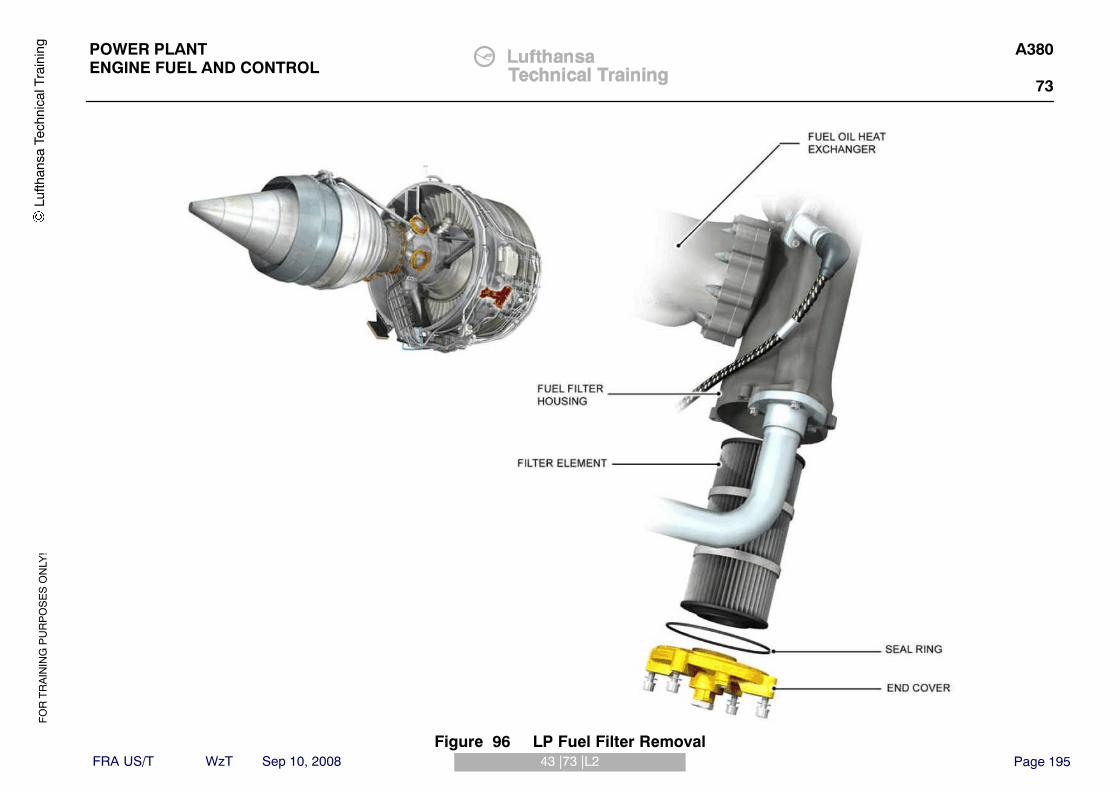
FO
R T
RA
ININ
G P
UR
PO
SE
S O
NLY
!
Page 19543 |73 |L2
POWER PLANTENGINE FUEL AND CONTROL
A380
73
FRA US/T WzT Sep 10, 2008
Lufth
ansa
Tec
hnic
al T
rain
ing
Figure 96 LP Fuel Filter Removal

FO
R T
RA
ININ
G P
UR
PO
SE
S O
NLY
!
Page 19644 |73 |L3
POWER PLANTENGINE FUEL AND CONTROL
A380
73
FRA US/T WzT Sep 10, 2008
INHIBIT THE ENGINE FUEL SYSTEM
If the aircraft or the engine is to be placed into storage for periods in excess of30 days, then the engine fuel system may be required to be inhibited to protectthe fuel system internal components. The storage conditions are given in theAMM Task 71−00−00−600−802−A.
Procedure:The procedure is given in AMM Task 71−00−00−600−806 and briefly describedbelow. Follow all Warnings & Cautions given in the AMM for your own safetyand the safety of others.1. Using the Onboard Maintenance Terminal (OMT) get access to the Power
Distribution Control Management pages and open, safety/lock and tag theapplicable circuit breakers as shown in the AMM.
2. Get access to the engine and open the fan cowl doors.A. On the inboard engines make sure that the thrust reverser is made
unserviceable for maintenance.3. Drain the fuel from the following engine fuel system component drain
points:A. a) FOHE, fuel pump, HMU, HP fuel supply, VSV extend and retract
tubes4. Inhibit the engine fuel system:
A. Disconnect the engine LP fuel supply tube at the pylon (Let the fueldrain into a clean container).
B. Connect the adapter HU41792 to the engine LP fuel supply tube.C. Prepare the inhibiting rig
WARNING: YOU MUST NOT PRESSURIZE THE RESERVOIR ABOVE 100PSIG AS THIS CAN CAUSE DAMAGE AND INJURY TOPERSONS.
5. Connect the delivery hose to the adapter on the LP fuel supply tube.6. Install new seal rings on the drain plugs removed in 3. (Note: Do not install
a new seal ring on the HMU drain plug as it will be necessary to install thistemporarily).
7. Supply mineral oil (OMat 1024) to the fuel system.A. Make sure the pressure gauge on the shows 50 psi (3.45 bar) and with
clean containers below the drain plugs, open the shut off valve on therig.
B. When fuel free mineral oil flows from the drains, install the drain plugs inthe following order:
C. FOHE, fuel pump, HMU, HP fuel supply & VSV fuel supply tube drainpoints
D. Wait 30 secs for the VSV actuators to fill then close the shut−off valveon the rig.
E. Remove the drain plug on the HMU and install the adapter HU80277and connect the other end of the adapter to the HP fuel supply tubedrain point
F. Open the shut−off valve on the rig and supply mineral oil to the fuelsystem until a fuel free flow comes from the LP turbine drain tube.
8. Disconnect the adapters and install the LP fuel supply tube and drain plugs.Install new seal rings, torque load and safety where necessary alldisconnected points.
Lufth
ansa
Tec
hnic
al T
rain
ing

FO
R T
RA
ININ
G P
UR
PO
SE
S O
NLY
!
Page 19744 |73 |L3
POWER PLANTENGINE FUEL AND CONTROL
A380
73
FRA US/T WzT Sep 10, 2008
Lufth
ansa
Tec
hnic
al T
rain
ing
Figure 97 Inhibiting the Engine Fuel System

FO
R T
RA
ININ
G P
UR
PO
SE
S O
NLY
!
Page 19801 |77 |L3 B2
POWER PLANTENGINE INDICATING
A380RR Trent 900
77
FRA US/T WzT Sep 10, 2008
ATA 77 ENGINE INDICATING
ENGINE & FADEC SYSTEMS OPS/CTL & IND (RR)
GeneralLet’s see the general view of the A380 cockpit.Lu
fthan
sa T
echn
ical
Tra
inin
g

FO
R T
RA
ININ
G P
UR
PO
SE
S O
NLY
!
Page 19901 |77 |L3 B2
POWER PLANTENGINE INDICATING
A380RR Trent 900
77
FRA US/T WzT Sep 10, 2008
Lufth
ansa
Tec
hnic
al T
rain
ing
Figure 98 FADEC System Ops/Ctl & ind

FO
R T
RA
ININ
G P
UR
PO
SE
S O
NLY
!
Page 20002 |77 |L3 B2
POWER PLANTENGINE INDICATING
A380RR Trent 900
77
FRA US/T WzT Sep 10, 2008
Engine Control Panels LocationThe engine control panels are located on the overhead panel:� The EIPM 1 & 2 reset circuit breakers,� The ENGINE FADEC GND PWR panel,� The ENGine FIRE panel,� The ENG MANual START panel with the ALTN MODE P/BSW,� The ENG START panel.
An A/THR (autothrust) P/B is located on the glareshield and on the pedestalthere are:� The THROTTLE CONTROL LEVERS with the instinctive disconnect P/Bs
and the reverser levers on the engine 2 and 3 only,� The ENG MASTER levers panel.
Lufth
ansa
Tec
hnic
al T
rain
ing

FO
R T
RA
ININ
G P
UR
PO
SE
S O
NLY
!
Page 20102 |77 |L3 B2
POWER PLANTENGINE INDICATING
A380RR Trent 900
77
FRA US/T WzT Sep 10, 2008
Lufth
ansa
Tec
hnic
al T
rain
ing
Figure 99 Engine Control Panels Location

FO
R T
RA
ININ
G P
UR
PO
SE
S O
NLY
!
Page 20203 |77 |L3 B2
POWER PLANTENGINE INDICATING
A380RR Trent 900
77
FRA US/T WzT Sep 10, 2008
EEC Powering / DepoweringBy setting the ENG START selector switch to the CRANK or IGN STARTposition with engines not running the FADEC is powered. The correspondingindication is clearly displayed on the EWD and the amber ”XX” which weredisplayed due to the absence of information are replaced by the main thrustparameters.Also when you press the FADEC GND PWR P/BSW to ON, the FADECparameters are clearly displayed on the EWD and the amber ”XX” are replacedby the main thrust parameters. If the FADEC GND PWR P/BSW remains ON,this means that the FADEC is powered for 10 min, except if OMS in interactivemode. In this case the FADEC stays automatically energized as long as youare in the related EEC tests menu. After these 10 min, on FADEC GND PWRpanel, the ON legend goes off automatically.
NOTE: The MASTER LEVER could be used for powering the FADEC.In this case, the dedicated FADEC will be powered for 15minutes, but it is not recommended on A/C, because there is arisk of the engine to be started if the rotary selector has beenforgotten in IGN START position.If you do so, observe quick ON and OFF action, because you donot have to forget that when the MASTER LEVER is set to ONthe LP fuel SOV is controlled to open.
If the EIPM reset switches are pulled for maintenance purposes, the dedicatedEECs are fail−safe powered. The ENGINE FIRE P/BSW also has effects onthe EEC powering/depowering. When this P/BSW is released out, it has effectson the various aircraft systems such as:� FADEC power supply is cut,� The hydraulic system: closure of the fire shut−off valves in order to isolate
the hydraulic pumps from the reservoir,� The electrical system,� The bleed system,� The fuel system: closure of the engine LP valve.
CAUTION: WITH ENG FIRE PUSH BUTTON RELEASED OUT, THE FIREEXTINGUISHERS ARE ARMED. DO NOT PRESS ON THEAGENT P/BSWS.
Lufth
ansa
Tec
hnic
al T
rain
ing

FO
R T
RA
ININ
G P
UR
PO
SE
S O
NLY
!
Page 20303 |77 |L3 B2
POWER PLANTENGINE INDICATING
A380RR Trent 900
77
FRA US/T WzT Sep 10, 2008
Lufth
ansa
Tec
hnic
al T
rain
ing
Figure 100 Indication Presentation − EEC Powering

FO
R T
RA
ININ
G P
UR
PO
SE
S O
NLY
!
Page 20404 |77 |L3 B2
POWER PLANTENGINE INDICATING
A380RR Trent 900
77
FRA US/T WzT Sep 10, 2008
Engine Parameters DisplayAmong the main parameters displayed on the EWD, you have the thrust modeindication (CLB, MCT, TO).The N1 and EGT indications are given as numerical values.The ECAM ENGINE page can be called by the selection of the ENG key on theECAM Control Panel (ACP) located on the pedestal.The secondary engine parameters, which are shown on the ECAM ENGINEpage, are:� IP rotor speed (N2),� HP rotor speed (N3),� Fuel Flow (FF),� Engine oil quantity (OIL QTY),� Engine oil temperature (OIL TEMP),� Engine oil pressure (OIL PRESS),� Engine rotor vibration levels (N1, N2, N3),� Nacelle temperature (NAC) from 0 to 500�C.
Lufth
ansa
Tec
hnic
al T
rain
ing

FO
R T
RA
ININ
G P
UR
PO
SE
S O
NLY
!
Page 20504 |77 |L3 B2
POWER PLANTENGINE INDICATING
A380RR Trent 900
77
FRA US/T WzT Sep 10, 2008
Lufth
ansa
Tec
hnic
al T
rain
ing
Figure 101 Indication Presentation − Engine Parameters Display

FO
R T
RA
ININ
G P
UR
PO
SE
S O
NLY
!
Page 20679 |77 |L3 B2
POWER PLANTENGINE INDICATING
A380RR Trent 900
77
FRA US/T WzT Sep 10, 2008
Throttle Control LeversThe Throttle Control Levers can be individually moved and manually only, theyare used to adjust the aircraft forward thrust. The range of the leversmovement is divided into 4 detent points: 0 (IDLE), CL for climb, FLX/MCT andTO/GA. When you supply an engine FADEC for example, by pushing theFADEC GND PWR P/BSW to ON and when you move the correspondingThrottle Control Lever, you will see the displacement of the cyan circle on theEWD THR indicator.The thrust mode corresponding to the lever position is also displayed on theupper part of the EWD.On the Throttle Control Leverl, are the reverser levers to control thedeployment or the stowing of the reversers and adjust the reverse thrust.These thrust reversers are installed on the engine 2 and 3 only.The reverser levers move between two detents: IDLE and full reverse thrust.Two A/THR instinctive disconnect P/BSWs (red) are located on the ThrottleControl Levers (engines 1 and 4 only). They direct input to all EECs in order todisconnect the A/THR function as soon as one of them is pushed.
A/THR P/BAn A/THR P/B is located on the FCU (Flight Control Unit) section of theglareshield. When it is pressed, three green lines on this P/BSW illuminate.The green lines go off when any instinctive disconnect P/B is pressed or whenyou press the A/THR P/B again.
Lufth
ansa
Tec
hnic
al T
rain
ing

FO
R T
RA
ININ
G P
UR
PO
SE
S O
NLY
!
Page 20779 |77 |L3 B2
POWER PLANTENGINE INDICATING
A380RR Trent 900
77
FRA US/T WzT Sep 10, 2008
Lufth
ansa
Tec
hnic
al T
rain
ing
Figure 102 Throttle Control Levers & A/THR P/B

FO
R T
RA
ININ
G P
UR
PO
SE
S O
NLY
!
Page 20801 |75 |L3
POWER PLANTAIR
A380
75
FRA US/T WzT Sep 10, 2008
ATA 75 ENGINE AIR SYSTEM
ENGINE AIRFLOW CONTROL INTRODUCTION
DescriptionThe engine compressor system is designed to produce high pressure ratios inthe higher RPM range in which the engine normally operates. In the lower RPMrange the airflow through the IP and HP compressors becomes unstableespecially during acceleration and deceleration. It is therefore necessary tohave airflow control devices to provide stable compressor airflow, duringstarting and lower power operation.The EEC controls the airflow control system.
IP Compressor Airflow ControlThe IP compressor airflow control system consists of:� Variable Inlet Guide Vanes (VIGVs) at the inlet to compressor� Two stages of Variable Stator Vanes (VSVs)� Three bleed valves at stage 8
The VIGVs and VSVs control the angle of the air supplied to the first threestages of the IP compressor. The angle of the VIGVs and VSVs is changed toadapt to different conditions of compressor operation and helps to preventcompressor stall/surge conditions.
HP Compressor Airflow ControlThe HP compressor airflow control system consists of three bleed valves atstage 3.
IP & HP Bleed ValvesAt lower engine speeds the bleed valves are open bleeding some of thecompressor airflow into the by−pass duct to prevent stall/surge conditions. Thebleed valves are closed at higher engine speeds to provide full airflow throughthe IP and HP compressors. All the bleed valves are two position valves onlyand are either open or closed.
Lufth
ansa
Tec
hnic
al T
rain
ing

FO
R T
RA
ININ
G P
UR
PO
SE
S O
NLY
!
Page 20901 |75 |L3
POWER PLANTAIR
A380
75
FRA US/T WzT Sep 10, 2008
Lufth
ansa
Tec
hnic
al T
rain
ing
Figure 103 Airflow Control System

FO
R T
RA
ININ
G P
UR
PO
SE
S O
NLY
!
Page 21002 |75 |L3
POWER PLANTAIR
A380
75
FRA US/T WzT Sep 10, 2008
VIGV/VSV CONTROL SYSTEM
OperationThe IP compressor VIGV/VSV system consists of the following units:� VIGV/VSV Control Valve in the HMU� Two VIGV/VSV Actuators� VIGV/VSV Actuating Mechanism
The EEC uses IP shaft speed, IP shaft acceleration, LP shaft speed, altitudeand T20 to schedule the VSV position. When these conditions change duringacceleration or deceleration the EEC will send a signal to the VIGV/VSVcontroller in the HMU. The controller responds by directing HP servo fuelpressure to position the actuators. The actuators are extended at low speedsand retract as the IP shaft speed increasesThe two actuators are each connected to a crankshaft assembly located at the3 o‘clock & 9 o‘clock positions. From each crankshaft assembly, there are 3output rods to the VIGV and VSV unison rings. The unison rings are connectedto the vane operating levers and as the unison ring moves, they change theangular position of each vane.Linear Variable Differential Transducers (LVDT), located inside the actuators,send signals back to the EEC confirming the position of the actuators.
Transient ControlThe control system modifies the actuator position schedule through all transientconditions, including engine acceleration, deceleration, reverse thrust operationand in the unlikely event of engine surge, transiently increasing handlingmargins.
Failsafe ControlIf the IP shaft speeds are not available, control is attempted using LP shaftspeed, whilst the fuel control system brings the engine speed to idle.If a failure of the electrical supply occurs, the system is designed to retract theactuators to the high−speed position. This minimises the risk of an overspeedevent that might otherwise occur if the actuators extend too fast relative to fuelflow control.
Engine ShutdownWhen the engine is shutdown, the EEC directs the VSV system to open theVIGVs & VSVs. This allows the IP rotor to be turned without the requirement todisconnect fuel lines and manually move the vanes to the open position. Duringstart, the EEC returns the VSV system back to the normal operating schedule.
Lufth
ansa
Tec
hnic
al T
rain
ing

FO
R T
RA
ININ
G P
UR
PO
SE
S O
NLY
!
Page 21102 |75 |L3
POWER PLANTAIR
A380
75
FRA US/T WzT Sep 10, 2008
Lufth
ansa
Tec
hnic
al T
rain
ing
Figure 104 VIGV/VSV Control System

FO
R T
RA
ININ
G P
UR
PO
SE
S O
NLY
!
Page 21203 |75 |L3
POWER PLANTAIR
A380
75
FRA US/T WzT Sep 10, 2008
VIGV/VSV ACTUATORS
PurposeThe two identical actuators provide the muscle force to move the VIGV/VSVmechanism to required position.
LocationMounted on brackets attached to the IP compressor case and the intermediatecasing at approximately the 3 & 9 o‘clock positions. The left actuator is justabove the engine centreline, the right actuator just below the engine centreline.
DescriptionThe actuators are powered by fuel pressure from the VSV actuator control inthe HMU. There are fuel lines to the extend and retract sides of the actuator.There is also a fuel drain line to collect fuel that leaks past the actuator seals.Each actuator has a single channel LVDT that provides a signal of actuatorposition to the EEC. The left actuator LVDT provides a signal to channel A, theright actuator provides a signal to channel B. The EEC channel in control onlyuses the input from it is own LVDT. If that signal is lost, it will then use the inputsignal from the other channel.
Lufth
ansa
Tec
hnic
al T
rain
ing

FO
R T
RA
ININ
G P
UR
PO
SE
S O
NLY
!
Page 21303 |75 |L3
POWER PLANTAIR
A380
75
FRA US/T WzT Sep 10, 2008
Lufth
ansa
Tec
hnic
al T
rain
ing
Figure 105 VSV Actuators

FO
R T
RA
ININ
G P
UR
PO
SE
S O
NLY
!
Page 21404 |75 |L3
POWER PLANTAIR
A380
75
FRA US/T WzT Sep 10, 2008
COMPRESSOR BLEED VALVE SYSTEM
IP / HP Bleed Valve Control SolenoidsThe EEC controls the bleed valves through the bleed valve solenoid units (2).The two units are located on the upper left and right sides of the IP compressorcase and control the bleed valves on their respective sides. Each solenoid unithas an HP3 air inlet connection and two electrical connectors to the EECChannels A and B. Each solenoid is dual wound, with control from each EECchannel.
IP Bleed ValvesThere are three poppet type IP compressor stage 8 bleed valves, eachcontrolled by a solenoid valve switching HP3 servo air. The bleed valves arespring−loaded in the normal open position with the engine not running. Afterstarting, with the engine at idle or above, sufficient air pressure will build up atthe valve inlet to close the bleed valves against the spring force. When thesolenoid is energised, the servo air system is pressurized and the bleed valveopens. When the valve solenoid is de−energized, the servo air system isvented and the bleed valve closes.
HP Bleed ValvesThere are three poppet type HP compressor stage 3 bleed valves, eachcontrolled by a solenoid valve switching HP3 servo air. Operation of the controlvalve solenoid and bleed valve is the same as that for the IP bleed valves.
NOTE: All the bleed valves bleed air into the by−pass duct when in theopen position.
Fault AnnunciationThe EEC can carry out continuity checks between the EEC and the bleed valvecontrollers and will set a fault message for failure of continuity. However, thereis no feedback to the EEC to confirm that the bleed valve has operatedcorrectly. If a bleed valve is not operating it will show itself by either of thefollowing:Valve open when it should be closed this will bleed air from the compressorat the higher rpm range and will show an increase in TGT. This may beobserved by the aircrew, but will certainly show itself on condition monitoring asa step change.Valve closed when it should be open - this is likely to show itself during startingwith a tendency to cause hung/hot starts.A bleed valve scheduling test can be carried out on the ground, with the enginerunning at idle. The EEC commands each of the bleed valves open & closedand reports any faults by monitoring changes in engine conditions.
Failsafe ControlIf a failure of the electrical supply occurs, the system is designed for thehandling bleed valves to automatically close (high speed position). This failuremode makes sure that the engine internal air pressure distribution does notadversely affect turbine cooling.
Lufth
ansa
Tec
hnic
al T
rain
ing

FO
R T
RA
ININ
G P
UR
PO
SE
S O
NLY
!
Page 21504 |75 |L3
POWER PLANTAIR
A380
75
FRA US/T WzT Sep 10, 2008
Lufth
ansa
Tec
hnic
al T
rain
ing
Figure 106 Bleed Valve System

FO
R T
RA
ININ
G P
UR
PO
SE
S O
NLY
!
Page 21605 |75 |L3
POWER PLANTAIR
A380
75
FRA US/T WzT Sep 10, 2008
BLEED VALVE SOLENOIDS
PurposeTo control the opening and closing of the three HP3 and three IP8 bleed valveson commands from the EEC.
LocationOne four−solenoid unit is installed on the left side of the IP compressor case.The other four−solenoid unit is installed on the right side of the IP compressorcase. Access by opening the C−ducts and removing the left and/or right uppercore fairing.
DescriptionThe two bleed valve solenoid units consist of eight independently operatedsolenoid valves in total. (3 for the IP8 bleed valves, 3 for the HP3 bleed valves,1 for the turbine case cooling valve and 1 for the NAI shut−off valve.There is one pneumatic connector (HP3) and two electrical connectors on eachunit, these supply electrical power and air to the solenoids. Each solenoid hastwo coils, one is connected to EEC channel A, the other to channel B. Theoutlets pneumatically connect the solenoids with the bleed valves.
Lufth
ansa
Tec
hnic
al T
rain
ing

FO
R T
RA
ININ
G P
UR
PO
SE
S O
NLY
!
Page 21705 |75 |L3
POWER PLANTAIR
A380
75
FRA US/T WzT Sep 10, 2008
CHANNEL A & BELECTRICALCONNECTORS
CHANNEL A & BELECTRICALCONNECTORS
Lufth
ansa
Tec
hnic
al T
rain
ing
Figure 107 Bleed Valve Solenoids

FO
R T
RA
ININ
G P
UR
PO
SE
S O
NLY
!
Page 21806 |75 |L3
POWER PLANTAIR
A380
75
FRA US/T WzT Sep 10, 2008
IP AND HP BLEED VALVES
LocationThe three IP8 and three HP3 bleed valve locations are shown opposite.The IP8 Bleed Valves are numbered and positioned as follows viewed lookingforwards:� No.1 − Top right� No.2 − Bottom right (blanking plate fitted to casing)� No.3 − Bottom left� No.4 − Top left
The HP3 Bleed Valves are numbered and positioned as follows viewed lookingforwards:� No.1 − Top right� No.2 − Bottom right� No.3 − Bottom left
Lufth
ansa
Tec
hnic
al T
rain
ing

FO
R T
RA
ININ
G P
UR
PO
SE
S O
NLY
!
Page 21906 |75 |L3
POWER PLANTAIR
A380
75
FRA US/T WzT Sep 10, 2008
Lufth
ansa
Tec
hnic
al T
rain
ing
Figure 108 IP/HP Handling Bleed Valves

FO
R T
RA
ININ
G P
UR
PO
SE
S O
NLY
!
Page 22007 |75 |L3
POWER PLANTAIR
A380
75
FRA US/T WzT Sep 10, 2008
COOLING & SEALING INTRODUCTIONThe engine is internally cooled with air supplied by the IP and HP compressors.This air is also used to seal bearing chambers to prevent internal leakage of oil.Air that is supplied by the IP compressor is taken from stages IP5 and IP8.Air that is supplied by the HP compressor is taken from stages HP3 and HP6.Parts of the engine, which are at different pressures, are isolated from eachother by labyrinth seals. The temperature of the cooling air around the IPturbine disc is monitored by the turbine overheat detection system.
Lufth
ansa
Tec
hnic
al T
rain
ing

FO
R T
RA
ININ
G P
UR
PO
SE
S O
NLY
!
Page 22107 |75 |L3
POWER PLANTAIR
A380
75
FRA US/T WzT Sep 10, 2008
Lufth
ansa
Tec
hnic
al T
rain
ing
Figure 109 Cooling & Sealing Airflows

FO
R T
RA
ININ
G P
UR
PO
SE
S O
NLY
!
Page 22208 |75 |L3
POWER PLANTAIR
A380
75
FRA US/T WzT Sep 10, 2008
VARIABLE STATOR VANES SYSTEM TEST
CAUTION: THIS TEST IS CARRIED OUT WHEN THE ENGINE IS BEINGDRY CRANKED.
DescriptionThe test is carried out through the On−board Maintenance Terminal (OMT).The engine is dry cranked to provide sufficient fuel pressure to move the VSVactuators when commanded by the EEC.The EEC commands the VSV actuators to move between the closed and openpositions and monitors the feedback signal from the LVDT‘s (Linear VariableDifferential Transducer) in each actuator to ensure they move to thecommanded position within a specified time.The test takes approximately 90 secs. If the N3 speed does not increase to asatisfactory value in 60 secs, the test is aborted.During the test a dry crank time indicator appears on the OMT screen and thisis replaced by a time indicator for the test, once the N3 speed has reached asatisfactory value.On completion, a message appears on the screen to command:� Rotary selector switch to NORM position� Engine Manual Start pushbutton to OFF� Remove the starter air
The Test result is then displayed. If the test failed then you should check forrelated Maintenance Messages.
Procedure:
NOTE: Obey the Instructions shown on the Onboard MaintenanceTerminal
1. Make a decision on which EEC channel you need to set during the test.2. Make sure the ENG MASTER lever is set to off3. Make sure the ENG START rotary selector is in the NORM position4. On the OMT, on the OMS home page, select:
A. SYSTEM REPORT/TESTB. ATA 73C. EECD. The applicable EEC
5. Start the test6. On completion of the test, put the aircraft back to its initial configuration.
Lufth
ansa
Tec
hnic
al T
rain
ing

FO
R T
RA
ININ
G P
UR
PO
SE
S O
NLY
!
Page 22308 |75 |L3
POWER PLANTAIR
A380
75
FRA US/T WzT Sep 10, 2008
Lufth
ansa
Tec
hnic
al T
rain
ing
Figure 110 Variable Stator Vane System Test

FO
R T
RA
ININ
G P
UR
PO
SE
S O
NLY
!
Page 22409 |75 |L3
POWER PLANTAIR
A380
75
FRA US/T WzT Sep 10, 2008
BLEED VALVE TESTS SCHEDULING
CAUTION: THIS TEST IS CARRIED OUT WHEN THE ENGINE IS BEINGGROUND RUN AT GROUND IDLE POWER.
DescriptionThe test is carried out through the On−board Maintenance Terminal (OMT).The engine is started to provide the air pressure to operate the bleed valveswhen commanded by the EEC.The test can be enabled for HP bleed valves only or can be enabled for boththe IP & HP bleed valve scheduling test.The EEC commands each bleed valve in turn (HP only or IP&HP valves) andmonitors the engine parameters during the test. If the EEC does not see achange in engine parameters when the bleed valve is operated between open& closed, then a fault message will be set.
Lufth
ansa
Tec
hnic
al T
rain
ing

FO
R T
RA
ININ
G P
UR
PO
SE
S O
NLY
!
Page 22509 |75 |L3
POWER PLANTAIR
A380
75
FRA US/T WzT Sep 10, 2008
Lufth
ansa
Tec
hnic
al T
rain
ing
Figure 111 Bleed Valve Testing Schedule

FO
R T
RA
ININ
G P
UR
PO
SE
S O
NLY
!
Page 22610 |75 |L3
POWER PLANTAIR
A380
75
FRA US/T WzT Sep 10, 2008
TURBINE CASE COOLING SYSTEM (TCC)
PurposeThe turbine case cooling system uses fan air to cool the HP, IP and LP turbinecases to maintain the turbine casings within satisfactory temperature limits. Italso controls the HP, IP and LP turbine casing thermal growth andconsequently controls the turbine blade running tip clearances, which improvesthe turbine efficiency.
Location of UnitsThe solenoid control valve is part of the Bleed Valve Solenoid pack on the leftside of the intermediate case in Zone 2.The TCC Valve assembly is located on the left side of the engine at thehorizontal centreline, to the rear of the PRSOV in the air offtake system inZone 3.
Lufth
ansa
Tec
hnic
al T
rain
ing

FO
R T
RA
ININ
G P
UR
PO
SE
S O
NLY
!
Page 22710 |75 |L3
POWER PLANTAIR
A380
75
FRA US/T WzT Sep 10, 2008
Lufth
ansa
Tec
hnic
al T
rain
ing
Figure 112 TCC System
FO
R T
RA
ININ
G P
UR
PO
SE
S O
NLY
!
Page 22811 |75 |L3
POWER PLANTAIR
A380
75
FRA US/T WzT Sep 10, 2008
TURBINE CASE COOLING SYSTEM (TCC)
DescriptionThe TCC valve assembly is a single line replaceable unit (LRU) interfacing withthe fan bypass air offtake and turbine cooling manifolds. The valve is a poppettype similar to the IP and HP handling bleed valves and is controlled by asolenoid valve switching HP3 servo air.
OperationThe TCC valve is spring−loaded in the closed position. When the solenoid isenergized, the servo system is pressurized and the bleed valve opens. Whenthe control valve solenoid is de−energized, the servo air system is vented andthe spring force closes the TCC valve. The control valve solenoid is connectedto both channels of the EEC and is driven by a signal from either channel A orB.
In Take−Off ConditionsThe TCC valve is in the closed position preventing flow to the HP and IPturbine cooling manifolds. However, a smaller amount of fan bypass air is stillallowed to flow into the LP turbine cooling manifold, thereby maintaining coolingto the LP turbine case.
In cruise conditionsThe TCC valve is opened allowing fan bypass air to flow into the HP, IP & LPturbine cooling manifolds. This contracts the combustion outer case, HP/IPturbine case and LP turbine case, reducing HP, IP and LP turbine blade tipclearances and thereby maintaining engine performance.
Failsafe ControlIf a failure of the electrical supply occurs, the system is designed for the TCCsolenoid to be de−energised, the servo line vented and the TCC valve closedby spring pressure.
Lufth
ansa
Tec
hnic
al T
rain
ing

FO
R T
RA
ININ
G P
UR
PO
SE
S O
NLY
!
Page 22911 |75 |L3
POWER PLANTAIR
A380
75
FRA US/T WzT Sep 10, 2008
Lufth
ansa
Tec
hnic
al T
rain
ing
Figure 113 TCC Operation

FO
R T
RA
ININ
G P
UR
PO
SE
S O
NLY
!
Page 23012 |75 |L3
POWER PLANTAIR
A380
75
FRA US/T WzT Sep 10, 2008
TCC MANIFOLD AND COOLING DUCT
DescriptionThe manifold and cooling duct assembly consists of the following items:� manifold inlet (HP and IP turbine)� manifold − 2 halves� 4 access panels� 4 sections of LPT cooling duct
Lufth
ansa
Tec
hnic
al T
rain
ing

FO
R T
RA
ININ
G P
UR
PO
SE
S O
NLY
!
Page 23112 |75 |L3
POWER PLANTAIR
A380
75
FRA US/T WzT Sep 10, 2008
Lufth
ansa
Tec
hnic
al T
rain
ing
Figure 114 TCC Duct Assembly

FO
R T
RA
ININ
G P
UR
PO
SE
S O
NLY
!
Page 23213 |75 |L3
POWER PLANTAIR
A380
75
FRA US/T WzT Sep 10, 2008
TURBINE OVERHEAT DETECTION SYSTEM
PurposeThe turbine overheat detection system monitors the temperature of the HP3cooling air at the front and rear of the IP turbine, and the IP8 cooling air at therear of the seal panel. A “TURBINE OVHT“ warning occurs on the E/WD in thecockpit if the temperature is more than the overheat limit.
LocationThe two thermocouple probes are located on the IP turbine case. The frontthermocouple assembly fits through the inside of one of the IP nozzle guidevanes and is located to the left of top dead centre. The rear thermocouple fitsthrough the inside of one of the LP1 nozzle guide vanes and is located on theright of bottom dead centre.
DescriptionThe turbine overheat detection system has two thermocouple probes whichmonitor the temperature. Each probe has two thermocouple elements, onesends a signal to EEC channel A, the other sends a signal to channel B. If thetemperature is more than the overheat limit, the EEC sends a signal to theAircraft via the AFDX outputs.The EEC will send a signal to the Aircraft when:� Both elements in the same thermocouple indicate the overheat limit� One element indicates the overheat limit and the other element in the same
thermocouple has a fault.
NOTE: If one element in the front thermocouple assembly and one in therear thermocouple assembly indicate the overheat limit the EECwill not signal an overheat.
Fault DetectionThe EEC monitors the thermocouple circuits for faults. Any faults aretransmitted to the Aircraft.
Lufth
ansa
Tec
hnic
al T
rain
ing

FO
R T
RA
ININ
G P
UR
PO
SE
S O
NLY
!
Page 23313 |75 |L3
POWER PLANTAIR
A380
75
FRA US/T WzT Sep 10, 2008
Lufth
ansa
Tec
hnic
al T
rain
ing
Figure 115 Turbine Overheat Detectors

FO
R T
RA
ININ
G P
UR
PO
SE
S O
NLY
!
Page 23414 |75 |L3
POWER PLANTAIR
A380
75
FRA US/T WzT Sep 10, 2008
NACELLE TEMPERATURE MONITORING
IntroductionThere are two air temperature sensors used to monitor the temperature of theair. One sensor is in engine zone 1 and one in engine zone 3.
Zone 1The engine Zone 1 fan compartment air temperature is continuously monitoredby the EEC, to make sure that it stays in limits. If the air temperature (T Zone1) becomes higher than the specified limit, the nacelle anti ice and starter ductvalves are closed and the EEC transmits an ADVISORY indication to the flightcrew.
Zone 3The engine Zone 3 air temperature is continuously monitored by the EEC, tomake sure that it stays in limits. If the air temperature (T Zone 3) becomeshigher than the specified limit, the EEC transmits an ADVISORY indication tothe flight crew.
Lufth
ansa
Tec
hnic
al T
rain
ing

FO
R T
RA
ININ
G P
UR
PO
SE
S O
NLY
!
Page 23514 |75 |L3
POWER PLANTAIR
A380
75
FRA US/T WzT Sep 10, 2008
Lufth
ansa
Tec
hnic
al T
rain
ing
Figure 116 Zone 1 and 3 Temperature Monitoring

FO
R T
RA
ININ
G P
UR
PO
SE
S O
NLY
!
Page 23615 |75 |L3
POWER PLANTENGINEAIR
A380
75
FRA US/T WzT Sep 10, 2008
FAN ZONE TEMPERATURE SENSOR
FunctionThe primary function of the Fan compartment Temperature Sensor is to detecta burst duct event. If the T zone 1 input signal to the EEC becomes higher thana temperature of 160 deg C (360 deg F), it transmits an ADVISORY indicationto the flight crew. The Nacelle anti−ice and starter duct valves supplying hot airare closed by the A/C systems.
LocationThe fan compartment temperature sensor is installed in engine zone 1 and isattached to the engine oil breather pipe located in the lower region of theengine zone. The sensor has a stainless steel housing which contains twotemperature−sensing elements.
DescriptionThe fan compartment temperature sensor has two 100−ohm platinumresistance temperature detectors (RTDs). The RTD elements are connected toeach EEC channel via simplex 2−wire cables, providing separate sensoroutputs for each channel. As the temperature in zone 1 increases, theresistance of the sensors will change sending a signal via the EEC.The T zone 1 signal will be made available to the Engine Monitoring Unit(EMU) through the EEC for engine health monitoring.
Lufth
ansa
Tec
hnic
al T
rain
ing

FO
R T
RA
ININ
G P
UR
PO
SE
S O
NLY
!
Page 23715 |75 |L3
POWER PLANTENGINEAIR
A380
75
FRA US/T WzT Sep 10, 2008
Lufth
ansa
Tec
hnic
al T
rain
ing
Figure 117 Zone 1 Temperature Sensor

FO
R T
RA
ININ
G P
UR
PO
SE
S O
NLY
!
Page 23816 |75 |L3
POWER PLANTAIR
A380
75
FRA US/T WzT Sep 10, 2008
ZONE 3 TEMPERATURE THERMOCOUPLE
PurposeThe Zone 3 Temperature Thermocouple (T Zone 3) is used to sense anincreasing air temperature resulting from leaking hot air ducts in the zone 3area.
LocationThe thermocouple is located on the left side of the engine and secured via abracket to the Turbine Case Cooling valve assembly.
DescriptionThe unit is a dual element insulated junction type thermocouple. The outputfrom each element is connected together to provide a single average output toChannel A of the EEC. Input to EEC channel B is provided by cross wiring fromchannel A. The temperature measurement is used to generate an indication inthe cockpit on the lower ECAM screenFlight deck notification (no crew action), is given when the temperature limit isexceeded to prompt maintenance action to determine the cause of thetemperature increase.Should the signal fail a range check then the nacelle temperature indication inthe cockpit turns amber and is replaced by XX.
Lufth
ansa
Tec
hnic
al T
rain
ing

FO
R T
RA
ININ
G P
UR
PO
SE
S O
NLY
!
Page 23916 |75 |L3
POWER PLANTAIR
A380
75
FRA US/T WzT Sep 10, 2008
Lufth
ansa
Tec
hnic
al T
rain
ing
Figure 118 Zone 3 NAC Temperature Thermocouple

FO
R T
RA
ININ
G P
UR
PO
SE
S O
NLY
!
Page 24001 |79 |L2
POWER PLANTOIL
A380RR Trent 900
79
FRA US/T WzT Sep 10, 2008
ATA 79 ENIGINE OIL SYSTEM
ENGINE OIL SYSTEM ARCHITECTURE
System ArchitectureThe engine oil system serves to lubricate and cool the engine internal drives,gears and bearings. The system is composed of:� an oil tank used for the storage of the oil,� an oil pump unit, which supplies pressure to move the oil to or from the
drives, gears and bearings,� a fuel oil heat exchanger, which decreases the oil temperature and
increases the fuel temperature,� a scavenge filter, which avoids unwanted particles in the re−circulated oil to
enter into the oil tank.The oil filter has a differential pressure transducer, which compares thedifference between upstream and downstream pressures to determine if thefilter is clogged. In this case, the difference will increase, and transducer willsend a signal to the cockpit FADEC (Full Authority Digital Engine Control).After data possessing, the FADEC will send a signal to the FWS (FlightWarning System) for cockpit indications.Each oil tank has an electric magnetic chip detector to attract magnetic debrisin the oil. This metallic oil contamination is shown on the ECAM and on theOMS (Onboard Maintenance System) devices for maintenance.
Lufth
ansa
Tec
hnic
al T
rain
ing

FO
R T
RA
ININ
G P
UR
PO
SE
S O
NLY
!
Page 24101 |79 |L2
POWER PLANTOIL
A380RR Trent 900
79
FRA US/T WzT Sep 10, 2008
Lufth
ansa
Tec
hnic
al T
rain
ing
Figure 119 Engine Oil System Architecture

FO
R T
RA
ININ
G P
UR
PO
SE
S O
NLY
!
Page 24202 |79 |L3
POWER PLANTOIL
A380
79
FRA US/T WzT Sep 10, 2008
OIL SYSTEM OVERVIEW
DescriptionThe engine oil system is a full flow recirculatory system. It must give adequatelubrication and cooling for all engine bearings, gears and driving splines duringall operating conditions.The complete system is divided into three primary areas:� The Feed oil and the cooling� The Return oil� The Vent, De−aeration and the Breather System
A self−contained oil tank is installed on the right side of the fan case. Itincorporates a quantity sight glass and provision is made for gravity oil filling.The system is vented through a centrifugal breather, installed on the rear faceof the external gearbox.
Oil CoolingThe cooling of the feed oil is achieved by a Fuel/Oil Heat Exchanger (FOHE),which controls the oil temperature in the limits.
Oil Filtration & InspectionA pressure filter, scavenge filter and line filters (last chance) provide thenecessary filtration. Location for magnetic chip detectors (MCDs) are providedin the scavenge lines.
Pump AssemblyThe pump assembly consists of a pressure pump element to move the oilaround the system, and nine scavenge pumps elements, as follows:� LP Turbine Bearing Chamber Scavenge Element� IP Turbine Bearing Chamber Scavenge Element� HP Turbine Bearing Chamber Scavenge Element� Internal Gearbox Front Scavenge Element� Internal Gearbox Rear Scavenge Element� Front Bearing Chamber Scavenge Element� The intermediate gearbox assembly (step aside gearbox) and gearbox input
drive (lower bevel box).� External Gearbox Scavenge Element� Centrifugal Breather Scavenge Element
Indications� The following indications are provided in the cockpit:� Oil tank quantity� Oil temperature� Oil pressure� Oil filter clog
Lufth
ansa
Tec
hnic
al T
rain
ing

FO
R T
RA
ININ
G P
UR
PO
SE
S O
NLY
!
Page 24302 |79 |L3
POWER PLANTOIL
A380
79
FRA US/T WzT Sep 10, 2008
Lufth
ansa
Tec
hnic
al T
rain
ing
Figure 120 Oil System Introduction

FO
R T
RA
ININ
G P
UR
PO
SE
S O
NLY
!
Page 24403 |79 |L3
POWER PLANTOIL
A380
79
FRA US/T WzT Sep 10, 2008
FEED OIL, LUBRICATION & COOLING
Feed oil is circulated by a single pressure pump, which draws oil from the oiltank through a gauze strainer. Additionally the pump has a pressure reliefvalve, which acts as a by−pass for cold starting and system blockageprotection.A 125−micron filter cleans feed oil. A differential pressure transducer monitorsfilter condition and provides a cockpit indication that the filter is becomingclogged, this switch is set to operate at a differential pressure of 23 psid.The FOHE will keep the oil temperature within limits.The FOHE has two functions:� To decrease the temperature of the oil� To increase the temperature of the fuel
An oil pressure relief valve protects the cooler core when the engine oil is verycold or if the core is blocked. An anti−syphon tube prevents oil suction from theFOHE during engine shut down.From the FOHE the feed oil is supplied through external tubes to the mainengine bearings, gears and drives.
Return Oil (Scavenge)The return oil/air is scavenged by nine pump elements in the pump modulefrom each of the eight primary lubricated locations of the engine and thebreather (air/oil separator).There are positions for installing nine (9) magnetic chip detectors (MCDs), tosample return oil from the engine main bearings and the gearboxes.The oil outlets from the scavenge pumps join to form a combined scavengereturn flow which is sampled by the electric master chip detector beforepassing through a 15−micron fine scavenge filter. The filter has a by−passvalve (20 psid) and a pressure differential transducer (13 psid) to give cockpitindication of impending by−pass.Temperature sensors in the return line between the scavenge pumps andscavenge filter provide cockpit indication of oil temperature.
De−aeration, Breather and Vent SystemLabyrinth oil seals and the sealing airflows from the engine compressors,prevents oil loss from the bearing chambers. The oversized scavenge pumpsand the vent pipes remove the sealing air, which flows continuously through theseals and into the bearing chambers. The return flow is an oil/air mixture.All scavenge oil is de−aerated when it enters the oil tank by a cyclone typeseparator. The air, which still contains a small amount of oil, is transferred tothe inlet of the centrifugal breather. The centrifugal breather separates the airand oil before discarding the air to atmosphere, the oil is scavenged from thebreather housing back into the combined scavenge line back to the oil tank.
Lufth
ansa
Tec
hnic
al T
rain
ing

FO
R T
RA
ININ
G P
UR
PO
SE
S O
NLY
!
Page 24503 |79 |L3
POWER PLANTOIL
A380
79
FRA US/T WzT Sep 10, 2008
Lufth
ansa
Tec
hnic
al T
rain
ing
Figure 121 Oil System

FO
R T
RA
ININ
G P
UR
PO
SE
S O
NLY
!
Page 24604 |79 |L3
POWER PLANTOIL
A380
79
FRA US/T WzT Sep 10, 2008
OIL TANK
PurposeTo store the engine oil.
LocationThe oil tank is attached to the A3 & A4 flanges of the LP compressor case onthe right side.
CapacityTank contents at the full mark: − 28 US Quarts
FeaturesThe tank is a magnesium casting to which other components attach to make upthe oil tank assembly. These components are as follows:� Oil quantity transmitter� Sight glass� Oil filler assembly� Scavenge filter assembly� Scavenge Filter Differential Pressure switch� Outlet tube� Vent tube� Electric Magnetic Chip Detector (EMCD)� Oil Temperature Sensors (2)
DescriptionThe oil tank provides the reservoir for the engine oil system. The feed line fromthe oil tank supplies the pressure pump, which feeds the oil system. There isalso a coarse filter in the tank to prevent contamination of the oil feed system.The scavenge pumps returns the oil from the various bearing chambers andgearboxes back to the oil tank, along with large quantities of air. A de−aeratorin the tank separates the oil and the air. The released air passes from the airspace at the top of the tank, via a vent tube to the centrifugal breather mountedon the gearbox.An anti−syphon line carries a small flow of oil from the main feed line back tothe oil tank, which is used to clean and cool the sight glass.The oil filler assembly has a quick release cap. Internally the filler has a flapvalve, which closes under engine running pressure maintaining sealing if thefiller cap is not fitted.
Lufth
ansa
Tec
hnic
al T
rain
ing

FO
R T
RA
ININ
G P
UR
PO
SE
S O
NLY
!
Page 24704 |79 |L3
POWER PLANTOIL
A380
79
FRA US/T WzT Sep 10, 2008
Lufth
ansa
Tec
hnic
al T
rain
ing
Figure 122 Oil Tank

FO
R T
RA
ININ
G P
UR
PO
SE
S O
NLY
!
Page 24805 |79 |L2
POWER PLANTOIL
A380RR Trent 900
79
FRA US/T WzT Sep 10, 2008
ENGINE OIL SERVICING
ServicingThe engine oil servicing is done by the filling of the engine oil system withapproved oil and by inspecting the system in order to find and correct theengine oil contamination.
Inspection of scavenge oil filterTo examine the scavenge filter element, it must be removed first. The presenceof particles has to be detected and these particles have to be removed. Thefilter and the filter housing have to be cleaned if magnetic particles are found inthe scavenge filter, the electric magnetic chip detector also has to beexamined. After examination of the particles, the filter and its seal have to bereplaced by new ones.The fuel and oil leak check on the scavenge filter housing is required beforeputting the aircraft back into operation.
Inspection of Electric Magnetic Chip DetectorTo examine the electric magnetic chip detector, it must be removed first. Thepresence of particles has to be detected and these particles have to beremoved. The detector and the particles are examined.After examination of the particles, the detector can be re−installed but the twoseal rings have to be replaced by new ones. The oil leak check on the detectorhousing is required before putting the aircraft back into operation.
Refill of engine oil tankBefore replenishing the oil tank, a visual check of the engine oil level in thesight glass of the oil tank must be done. If the engine has been stopped formore than six hours; the engine has to be operated at IDLE before refilling theoil tank by respecting the duration between engine shutdown and the oil tankrefilling. To refill the tank, the oil filler cap is removed and the engine lubricatingoil also known as material No.OMat 1011 is added. The check for fuel fumes in the tank is required beforeputting the aircraft back into operation.
HUMAN FACTOR POINTS:
WARNING: YOU MUST WAIT FOR A MINIMUM OF 10 MINUTES AFTERTHE ENGINE HAS STOPPED BEFORE YOU DO A CHECK OFTHE OIL LEVEL. THIS WILL LET THE OIL LEVEL BECOMESTABLE AND THIS WILL PREVENT OIL SPLASH DUE TORESIDUAL PRESSURE.
CAUTION: AVOID SPILLAGE WHEN SERVICING OIL.
Lufth
ansa
Tec
hnic
al T
rain
ing

FO
R T
RA
ININ
G P
UR
PO
SE
S O
NLY
!
Page 24905 |79 |L2
POWER PLANTOIL
A380RR Trent 900
79
FRA US/T WzT Sep 10, 2008
Lufth
ansa
Tec
hnic
al T
rain
ing
Figure 123 Engine Oil − Servicing

FO
R T
RA
ININ
G P
UR
PO
SE
S O
NLY
!
Page 25005 |79 |L2
POWER PLANTOIL
A380RR Trent 900
79
FRA US/T WzT Sep 10, 2008
WARNING: BE CAREFUL, THE ENGINE PARTS (BLEED DUCT, OIL TANK)CAN STAY HOT FOR ALMOST 1 HOUR AFTER SHUTDOWN.
Lufth
ansa
Tec
hnic
al T
rain
ing

FO
R T
RA
ININ
G P
UR
PO
SE
S O
NLY
!
Page 25105 |79 |L2
POWER PLANTOIL
A380RR Trent 900
79
FRA US/T WzT Sep 10, 2008
Lufth
ansa
Tec
hnic
al T
rain
ing
Figure 124 Engine Oil − Servicing Cautions

FO
R T
RA
ININ
G P
UR
PO
SE
S O
NLY
!
Page 25206 |79 |L3
POWER PLANTOIL
A380
79
FRA US/T WzT Sep 10, 2008
OIL QUANTITY TRANSMITTER
PurposeThe oil quantity transmitter measures the quantity of engine oil in the oil tank toprovide a cockpit indication.
LocationInstalled into the top of the oil tank and secured by bolts in the mounting boss.Access by opening the right fan cowl.
DescriptionThe oil quantity transmitter is a potentiometer style device with changes inresistance indicating different oil levels. The transmitter consists of a series ofreed switches and resistors that form a ladder activated by a float containing apermanent magnet.As the float moves along the stack different reed switches are activatedthereby changing resistance. The EEC provides a constant current to thetransmitter and as the resistance changes, this results in a change in theoutput voltage across the resistance stack. The output voltage is measured bychannel B of the EEC, which conditions the signal and transmits the oil quantitylevel to the Electronic Instrument System (EIS) for cockpit display on the lowerECAM (System Display) screen. (Also displayed on ECAM CRUISE page).The needle and the digital indication are normally green. If the oil quantitydrops below 4 quarts the digital indication pulses.
Lufth
ansa
Tec
hnic
al T
rain
ing

FO
R T
RA
ININ
G P
UR
PO
SE
S O
NLY
!
Page 25306 |79 |L3
POWER PLANTOIL
A380
79
FRA US/T WzT Sep 10, 2008
Lufth
ansa
Tec
hnic
al T
rain
ing
Figure 125 Oil Quantity Transmitter

FO
R T
RA
ININ
G P
UR
PO
SE
S O
NLY
!
Page 25407 |79 |L3
POWER PLANTOIL
A380
79
FRA US/T WzT Sep 10, 2008
OIL PUMP AND PRESSURE FILTER ASSEMBLY
PurposeThe oil pump and pressure filter housing supplies the pressurised oil tolubricate the engine bearings and gears. The pump assembly also scavengesoil back to the oil tank.The filter housing contains the pressure oil filter that cleans the feed oil.
LocationThe oil pump and pressure filter assembly is installed on the rear face of theexternal gearbox between the centrifugal breather and the lower bevel gearbox.
Oil Pump DescriptionThe vane type oil pump assembly consists of a pressure pump and ninescavenge pumps to scavenge oil from the various areas of the engine back tothe oil tank.The pressure pump has a pressure relief valve, this protects the system forcold starting and blockage protection and is set to 600 psi. The relief valveopens and oil is fed back to the pump inlet, which reduces the systempressure.
Pressure Filter DescriptionThe pressure filter is installed inside the filter housing, access can be gained byremoval of the filter cover. The filter is a 125 micron cleanable type filter andhas a life of 3 cleans.The filter is a non−bypass type.A check valve in the housing prevents the loss of oil when the filter is changed.The housing also contains an anti−leak valve to prevent oil draining back to thepump when the engine is shut down.
Lufth
ansa
Tec
hnic
al T
rain
ing

FO
R T
RA
ININ
G P
UR
PO
SE
S O
NLY
!
Page 25507 |79 |L3
POWER PLANTOIL
A380
79
FRA US/T WzT Sep 10, 2008
Lufth
ansa
Tec
hnic
al T
rain
ing
Figure 126 Oil Pump Assembly & Pressure Filter

FO
R T
RA
ININ
G P
UR
PO
SE
S O
NLY
!
Page 25608 |79 |L3
POWER PLANTOIL
A380
79
FRA US/T WzT Sep 10, 2008
MAGNETIC CHIP DETECTORS (MCDS)
PurposeA Vickers Electric Master Chip Detector (EMCD) and nine Muirhead Vatricscrew−in magnetic chip detectors are installed in the return oil system to allowmonitoring of the following:� Front Bearing Housing� Internal Gearbox (Front)� Internal Gearbox (Rear)� HP Turbine Bearing Chamber� IP Turbine Bearing Chamber� LP Turbine Bearing Chamber� Intermediate and Lower Bevel Gearboxes� External Gearbox� Centrifugal Breather
LocationThe EMCD is installed in the combined scavenge return line on the forwardside of the oil tank.There are nine ports on the bottom of the oil pump which can be used to installadditional MCDs..
NOTE: During normal engine operation, only the Master EMCD isinstalled. If metallic particles are found on the EMCD duringinspection, diagnostic MCD‘s can then be installed to isolate thesource of the debris.
Electric MCDThe Electric MCD is positioned at the inlet to the scavenge filter and collectsferrous metal particles from the engine oil. The head of the EMCD has twoelectrically isolated magnetic poles. A circuit is made when debris bridges thetwo poles. The EMU continuously monitors the EMCD during flight andgenerates a EMCD debris maintenance message 10 secs after landing whichis sent to the Aircraft via the EEC.
Screw−in MCDThe screw−in MCD assembly consists of a housing and Magnetic ChipDetector, which has a magnetic end. When the MCD is installed the magneticend is located in the return (scavenge) oilways.The MCD housing contains a self−closing check valve to prevent oil leakagewhen the MCD is removed for inspection.If metallic particles are found on the EMCD during inspection, MCDs can beinstalled in the ports on the oil pump assembly. This allows the problem to beisolated by checking each scavenge oil line.
Lufth
ansa
Tec
hnic
al T
rain
ing

FO
R T
RA
ININ
G P
UR
PO
SE
S O
NLY
!
Page 25708 |79 |L3
POWER PLANTOIL
A380
79
FRA US/T WzT Sep 10, 2008
ELECTRIC MAGNETIC CHIP DETECTORLufth
ansa
Tec
hnic
al T
rain
ing
Figure 127 Magnetic Chip Detector Locations

FO
R T
RA
ININ
G P
UR
PO
SE
S O
NLY
!
Page 25809 |79 |L3
POWER PLANTOIL
A380
79
FRA US/T WzT Sep 10, 2008
SCAVENGE FILTER ASSEMBLY
PurposeTo remove contamination from the scavenge oil that is returning to the oil tank.
LocationInstalled on the rear of the oil tank on the right side of the fan case.
DescriptionThe assembly consists of the following items:� Scavenge filter assembly (15 micron)� Scavenge filter differential pressure switch� Scavenge filter by−pass valve
Scavenge FilterThe scavenge filter element cleans the combined scavenge oil returning to theoil tank. The filter element is a non−cleanable, throw away type filter. If the filterelement becomes clogged, the by−pass valve opens and allows the oil to flowdirectly back to the tank.
Scavenge Filter Differential Pressure SwitchThe scavenge filter differential pressure switch monitors the pressure at theinlet & outlet of the filter and provides an indication when the filter becomespartially clogged. The switch is set at 13 psid.
NOTE: The EEC will inhibit the filter clog message when oil temperatureis low, to prevent nuisance messages.
Scavenge Filter By−pass ValveThe scavenge filter is fitted with a by−pass valve which operates independentlyof the differential pressure switch. The by−pass valve operates at 20 psid tomaintain oil flow in the event of scavenge filter blockage.
Lufth
ansa
Tec
hnic
al T
rain
ing

FO
R T
RA
ININ
G P
UR
PO
SE
S O
NLY
!
Page 25909 |79 |L3
POWER PLANTOIL
A380
79
FRA US/T WzT Sep 10, 2008
Lufth
ansa
Tec
hnic
al T
rain
ing
Figure 128 Oil Scavenge Filter

FO
R T
RA
ININ
G P
UR
PO
SE
S O
NLY
!
Page 26010 |79 |L3
POWER PLANTOIL
A380
79
FRA US/T WzT Sep 10, 2008
CENTRIFUGAL BREATHER
PurposeTo remove the oil from the vent air, before discarding the air overboard.
LocationInstalled in the external gearbox, and located on the rear face between the oilpump and the fuel pump.
DescriptionThe centrifugal breather has a rotor that contains retimet segments and isdriven by the external gearbox.Aerated oil from the bearing chamber vent system and the oil tank is deliveredto the centrifugal breather. The aerated oil tries to pass through the retimetsegments but is centrifuged out. The air can pass through the retimetsegments into the hollow rotor and is vented overboard. The centrifuged oil isscavenged back to the oil tank by the breather scavenge pump element.
Lufth
ansa
Tec
hnic
al T
rain
ing

FO
R T
RA
ININ
G P
UR
PO
SE
S O
NLY
!
Page 26110 |79 |L3
POWER PLANTOIL
A380
79
FRA US/T WzT Sep 10, 2008
Lufth
ansa
Tec
hnic
al T
rain
ing
Figure 129 Centrifugal Filter

FO
R T
RA
ININ
G P
UR
PO
SE
S O
NLY
!
Page 26211 |79 |L3
POWER PLANTOIL
A380
79
FRA US/T WzT Sep 10, 2008
FUEL/OIL HEAT EXCHANGER (FOHE)
PurposeThe FOHE has two functions as follows:� To reduce the temperature of the engine oil� To prevent the water content of the fuel from turning to ice.
LocationThe FOHE is mounted horizontally below the oil tank on the right side of thefan case.
DescriptionThe FOHE consists of the following units:� FOHE matrix core� By−pass Valve� Oil pressure transmitters (2)� Low oil pressure switch� LP Fuel Filter� Fuel Filter Differential Pressure Switch
FOHE Matrix CoreHeat is transferred from the oil to the fuel in the core of the FOHE. The oil flowis made slower by many baffle plates around the steel tubes through which thefuel is flowing. The slower oil flow enhances the exchange of heat.An anti−syphon hole connects the inlet to outlet to prevent oil suction from theFOHE during engine shut down.
By−pass ValveIf the oil pressure in the FOHE becomes more than a specified limit a by−passvalve will open allowing the oil to by−pass approximately two−thirds of the core.This normally occurs when the engine oil is extremely cold.
Oil Pressure Transmitters & Low Oil Pressure SwitchDescription on page 6−19
LP Fuel Filter, Differential Pressure Switch & By−pass ValveDescription in Fuel System
Lufth
ansa
Tec
hnic
al T
rain
ing

FO
R T
RA
ININ
G P
UR
PO
SE
S O
NLY
!
Page 26311 |79 |L3
POWER PLANTOIL
A380
79
FRA US/T WzT Sep 10, 2008
Lufth
ansa
Tec
hnic
al T
rain
ing
Figure 130 Fuel/Oil Heat Exchanger (FOHE)

FO
R T
RA
ININ
G P
UR
PO
SE
S O
NLY
!
Page 26412 |79 |L3
POWER PLANTOIL
A380
79
FRA US/T WzT Sep 10, 2008
OIL PRESSURE INDICATION
PurposeThe oil pressure transducers (2) assembly measures the differential oilpressure between the output of the oil pump and the internal gearbox chamberscavenge line.
LocationThe oil pressure transducers assembly is installed on the FOHE assembly.Access by opening the right fan cowl door.
DescriptionThe oil pressure transducer assembly consists of two transducers supplied bythe same oil pressures. They are ratiometric devices supplied with a constantreference voltage, as the pressure changes the internal resistance of thetransducers change, resulting in variable voltage outputs, which are read by theEEC. One pressure transducer provides a signal to EEC channel A, the othertransducer provides a signal to channel B. The EEC conditions and filters thesignal to remove pump ripple effects and sends the smooth oil pressure signalto the EIS for cockpit display on the lower ECAM screen.The needle and the digital indication are normally green. The needle and thedigital indication will turn red if the oil pressure drops below 25 psi.
Oil Pressure Limits� Minimum oil pressure 25 psi.
LOW OIL PRESSURE SWITCH
PurposeThe low oil pressure switch measures the same differential oil pressure as theoil pressure transducers to provide an indication when the oil pressure drops toa pre−set level.
LocationThe switch is installed on the FOHE.
DescriptionWhen the differential oil pressure falls below the switch pre−set value, theinternal contacts close indicating a loss of oil pressure. The output of the switchis fed directly to the aircraft system (AFDX) and from there to the EEC.
Low Oil Pressure IndicationOil pressure warnings are provided for two conditions:� Oil pressure less than an N3 related value (Amber)� Oil pressure less than the minimum threshold (Red)
The amber minimum oil pressure is proportional to N3 and is output to thecockpit display to help format the oil pressure display. When the oil pressurefalls below the amber value but remains above the low pressure switch limit,the cockpit display will become amber and a maintenance message will be set.When the oil pressure falls below the threshold value a Red Alert is set. This isderived from the 3 inputs, the oil pressure transducers and low oil pressureswitch. With the engine running 2 out of the 3 inputs are required to enunciatethe low oil pressure condition.
Lufth
ansa
Tec
hnic
al T
rain
ing

FO
R T
RA
ININ
G P
UR
PO
SE
S O
NLY
!
Page 26512 |79 |L3
POWER PLANTOIL
A380
79
FRA US/T WzT Sep 10, 2008
Lufth
ansa
Tec
hnic
al T
rain
ing
Figure 131 Oil Pressure Indication

FO
R T
RA
ININ
G P
UR
PO
SE
S O
NLY
!
Page 26613 |79 |L3
POWER PLANTOIL
A380
79
FRA US/T WzT Sep 10, 2008
OIL PRESSURE FILTER DELTA P TRANSDUCER
PurposeThe oil pressure filter differential pressure (dP) transducer monitors thecondition of the filter element in the oil pressure filter. It provides a cockpitindication of impending filter blockage.
LocationThe pressure filter dP transducer is located on the oil pump & pressure filterassembly. Access to the unit is via the right fan cowl.
DescriptionThe oil pressure filter differential pressure transducer measure the pressuredrop across the filter element. The transducer is a ratiometric device suppliedwith a constant reference voltage. As the pressure changes, the internalresistance of the device changes resulting in a variable voltage output that isread by the EEC. As the filter becomes clogged with debris, the pressure dropincreases and when it reaches a pre−determined level, the filter is consideredto be blocked.The pressure filter dP transducer sends the output signal to channel B of theEEC.Note: When the oil temperature is too low, the EEC will inhibit the filter blockindications, to prevent nuisance indications.
IndicationsImpending blockage of either the pressure filter or scavenge filter will give thefollowing indications:
Engine Warning Display (EWD)� OIL FILTER CLOG message� Aural Warning� Master Caution
System Display (SD)� Amber CLOG message
Lufth
ansa
Tec
hnic
al T
rain
ing

FO
R T
RA
ININ
G P
UR
PO
SE
S O
NLY
!
Page 26713 |79 |L3
POWER PLANTOIL
A380
79
FRA US/T WzT Sep 10, 2008
Lufth
ansa
Tec
hnic
al T
rain
ing
Figure 132 Oil Pressure Filter dP Transducer

FO
R T
RA
ININ
G P
UR
PO
SE
S O
NLY
!
Page 26814 |79 |L3
POWER PLANTOIL
A380
79
FRA US/T WzT Sep 10, 2008
OIL SCAVENGE FILTER DELTA P TRANSDUCER
PurposeThe oil scavenge filter differential pressure (dP) transducer monitors thecondition of the filter element in the oil scavenge filter. It provides a cockpitindication of impending filter blockage.
LocationThe scavenge filter dP transducer is located on the oil tank. Access to the unitsis via the right fan cowl.
DescriptionThe Scavenge oil filter differential pressure transducer measures the pressuredrop across the filter element. The transducer is a ratiometric device suppliedwith a constant reference voltage. As the pressure changes, the internalresistance of the device changes resulting in a variable voltage output that isread by the EEC. As the filter becomes clogged with debris, the pressure dropincreases and when it reaches a pre−determined level, the filter is deemed tobe blocked.The scavenge filter dP transducer send the output signal to channel B of theEEC.
NOTE: When the oil temperature is too low, the EEC will inhibit the filterblock indications, to prevent nuisance indications.
IndicationsImpending blockage of either the pressure filter or scavenge filter will give thefollowing indications:
Engine/Warning Display (E/WD)� OIL FILTER CLOG message� Aural Warning� Master Caution
System Display (SD)� Amber CLOG message
Lufth
ansa
Tec
hnic
al T
rain
ing

FO
R T
RA
ININ
G P
UR
PO
SE
S O
NLY
!
Page 26914 |79 |L3
POWER PLANTOIL
A380
79
FRA US/T WzT Sep 10, 2008
Lufth
ansa
Tec
hnic
al T
rain
ing
Figure 133 Oil Scavenge Filter dP Transducer

FO
R T
RA
ININ
G P
UR
PO
SE
S O
NLY
!
Page 27015 |79 |L3
POWER PLANTOIL
A380
79
FRA US/T WzT Sep 10, 2008
OIL TEMPERATURE SENSOR
PurposeThe oil temperature sensors within the engine oil system are used to sense thescavenge oil.
LocationThe two temperature sensors are installed on the oil tank in the scavengereturn line..
DescriptionThe sensors are resistance temperature devices (RTD‘s) which have a variableresistance with temperature. Each temperature sensor sends a signal to onechannel of the EEC. The EEC processes the output of the sensors andprovides an output for cockpit display. Oil temperature is also used for startingand accel fuel scheduling.The EEC continuously monitors the outputs of the RTD‘s. In the event of afailure of one of the sensors, the EEC shall select the remaining valid sensor.When there is a disagreement between the two measurements, the higher ofthe two values will be selected.
IndicationsThe oil temperature displays in degrees C on the ECAM SD screen and isnormally green. The indication turns Amber if the temperature exceeds TBD �C.
Engine/Warning Display (E/WD)� OIL LO TEMP� OIL HI TEMP� Aural Warning� Master Caution
System Display (SD)� Engine STATUS page
Lufth
ansa
Tec
hnic
al T
rain
ing

FO
R T
RA
ININ
G P
UR
PO
SE
S O
NLY
!
Page 27115 |79 |L3
POWER PLANTOIL
A380
79
FRA US/T WzT Sep 10, 2008
Lufth
ansa
Tec
hnic
al T
rain
ing
Figure 134 Oil Temperature Sensor

FO
R T
RA
ININ
G P
UR
PO
SE
S O
NLY
!
Page 27216 |79 |L2
POWER PLANTOIL
A380
79
FRA US/T WzT Sep 10, 2008
OIL SYSTEM SERVICING
(AMM 79−00−00−610−801)
WARNING: YOU MUST BE CAREFUL WHEN YOU DO WORK ON THEENGINE PARTS AFTER THE ENGINE IS SHUT DOWN. THEENGINE PARTS CAN STAY HOT FOR ALMOST 1 HOUR.
WARNING: YOU MUST NOT TOUCH HOT PARTS WITHOUTAPPLICABLE GLOVES. IF YOU GET AN INJURY PUT IT INCOLD WATER FOR 10 MINUTES AND GET MEDICAL AID.
WARNING: YOU MUST NOT LET ENGINE OIL STAY ON YOUR SKIN.FLUSH THE OIL FROM YOUR SKIN WITH WATER. YOUMUST NOT BREATHE THE FUMES. YOU MUST NOT GET OILIN YOUR EYES OR MOUTH. PUT ON GOGGLES OR A FACEMASK. IF YOU GET OIL IN YOUR MOUTH, YOU MUST NOTCAUSE VOMITING BUT GET MEDICAL AID IMMEDIATELY.
Procedure:The procedure in the AMM is briefly described below:� On the OMT, get access to the Power Distribution Control management
pages and open & safety the applicable circuit breakers� Open the oil tank access panel in the right fan cowl door� Do a visual check of the oil level in the oil tank sight glass
NOTE: You must wait at least 10 minutes after engine shutdown for theoil level to become stable.
NOTE: If the engine rpm was not stabilised at idle before engineshutdown, the oil system will not have become stable. In thiscondition the oil quantity indication can apparently be low, this isnormal and the engine oil system must not be filled.
� If the engine has been stopped for less than 6 hours and the oil level is low,fill the engine oil tank.
� If the engine has been stopped for more than 6 hours and the oil level islow, but not below 4.73 litres (5 US quarts) from the required level, then:− Do not fill the engine oil system− Start the engine and operate at idle for 5 minutes− Stop the engine− Do a check of the engine oil level again (after waiting at least 10 minutes
for the oil level to become stable)− If the oil level is low, fill the oil tank
� If the engine has been stopped for more than 6 hours and the oil level isbelow 4.73 litres (5 US quarts) from the required level, then:− Drain the external gearbox (AMM 79−00−00−680−801)− Fill the engine oil tank− Start the engine and operate at idle for 5 minutes− Do a check of the engine oil level again (after waiting at least 10 minutes
for the oil level to become stable)− If the oil level is low, fill the oil tank
Notes:1. Add clean approved engine oil (Omat 1011) to the tank.2. Check for fuel fumes when you remove the oil tank cap (fuel fumes are
easier to find when the oil is hot) AMM task 79−00−00−280−8013. Check condition of seal ring in the groove of the oil filler cap before
installing. Replace if loose or damaged.
Lufth
ansa
Tec
hnic
al T
rain
ing

FO
R T
RA
ININ
G P
UR
PO
SE
S O
NLY
!
Page 27316 |79 |L2
POWER PLANTOIL
A380
79
FRA US/T WzT Sep 10, 2008
Lufth
ansa
Tec
hnic
al T
rain
ing
Figure 135 Oil System Servicing

FO
R T
RA
ININ
G P
UR
PO
SE
S O
NLY
!
Page 27417 |79 |L2
POWER PLANTOIL
A380
79
FRA US/T WzT Sep 10, 2008
OIL SCAVENGE FILTER REMOVAL/INSTALLATION
(AMM 79−22−45)
ATTENTION: Warnings and Cautions:Observe all Warnings and Cautions given in the AMM
Removal Procedure:The procedure in the AMM is briefly described below:� On the OMT, get access to the Power Distribution Control management
pages and open & safety the applicable circuit breakers� Open the right fan cowl door� Put a clean 10 L container into position to catch the oil� Remove the drain plug from the filter housing and drain the oil into the
container (Do not discard the oil at this step)� Remove seal from the drain plug, install a new seal and refit the drain plug
in the housing and torque� Hold the housing and remove the bolts and washers� Carefully remove the housing and filter from the scavenge filter cover� Examine the element and the drained oil for contamination (AMM Task
79−00−00−280−801)� Discard the element� Remove and discard the seal ring
Installation Procedure� Examine the inner area of the housing and make sure it is clean and clear
of unwanted material� Install a new seal ring to the housing� Carefully install the filter element in the scavenge filter cover. Make sure you
hold the filter element in this position.� Put the housing in position on the scavenge filter cover� Attach the housing with the bolts and washers� Torque the bolts to the value given in the AMM� Fill the engine oil system� Do a fuel and oil leak check of the scavenge filter housing� Put the aircraft back to its initial configuration
Lufth
ansa
Tec
hnic
al T
rain
ing

FO
R T
RA
ININ
G P
UR
PO
SE
S O
NLY
!
Page 27517 |79 |L2
POWER PLANTOIL
A380
79
FRA US/T WzT Sep 10, 2008
Lufth
ansa
Tec
hnic
al T
rain
ing
Figure 136 Oil Scavenge Filter Removal

FO
R T
RA
ININ
G P
UR
PO
SE
S O
NLY
!
Page 27618 |79 |L2
POWER PLANTOIL
A380
79
FRA US/T WzT Sep 10, 2008
OIL PRESSURE FILTER REMOVAL/INSTALLATION
(AMM 79−22−43)
ATTENTION: Warnings and Cautions:Observe all Warnings and Cautions given in the AMM
Removal Procedure:The procedure in the AMM is briefly described below:� On the OMT, get access to the Power Distribution Control management
pages and open & safety the applicable circuit breakers� Open the right fan cowl door� Put a clean container into position to catch the oil� Remove the lockwire or safety cable that safeties the housing� Turn the housing counter clockwise to release it (Use a strap wrench if
necessary)� Carefully remove the housing and filter element from the oil pump assembly
CAUTION: MAKE SURE YOU REMOVE THE ELEMENT WITH THEHOUSING. IF THE FILTER ELEMENT IS NOT REMOVED ATTHE SAME TIME IN CAN FALL AND DAMAGE THE PART
� Drain the oil from the housing and element into a clean container� Remove and discard the seal ring� Examine the element and the drained oil for contamination (AMM Task
79−00−00−200−804)
NOTE: The element can be cleaned and used again� Put the element into a clean container for its protection
Installation Procedure� Make sure there is a new seal ring installed on the new element� Install a new seal ring on the housing� Carefully install the filter element in the oil pump assembly. Make sure you
hold the filter element in this position.� Put the housing in position on the oil pump assembly� Turn the housing in a clockwise direction with your hand until it is tight
NOTE: You must only tighten the filter housing with your hand only. Ifyou use tools you can cause damage to the screw threads.
� Safety the housing with lockwire or Safety Cable� Fill the engine oil system� Do a fuel and oil leak check of the pressure filter housing� Put the aircraft back to its initial configuration
Lufth
ansa
Tec
hnic
al T
rain
ing

FO
R T
RA
ININ
G P
UR
PO
SE
S O
NLY
!
Page 27718 |79 |L2
POWER PLANTOIL
A380
79
FRA US/T WzT Sep 10, 2008
Lufth
ansa
Tec
hnic
al T
rain
ing
Figure 137 Oil Pressure Filter Removal

FO
R T
RA
ININ
G P
UR
PO
SE
S O
NLY
!
Page 27819 |79 |L2y
POWER PLANTOIL
A380
79
FRA US/T WzT Sep 10, 2008
EMCD INSPECTION
(AMM TASK 79−00−00−200−802)
ATTENTION: Warnings and Cautions:Observe all Warnings and Cautions given in the AMM
Procedure:The procedure in the AMM is briefly described below:� On the OMT, get access to the Power Distribution Control management
pages and open & safety the applicable circuit breakers� Open the right fan cowl door� Remove the master EMCD� Put the master EMCD probe into clean kerosene and remove the oil (The
kerosene should be in a clean non−metallic container) Make sure you donot contaminate the electrical contacts with kerosene
NOTE: Be careful to only remove the oil from the EMCD and not anycontamination, which may be present.
� Examine the master EMCD in good light for contamination using a 05Xmagnifying glass
� Refer to the contamination standards in the AMM. (The types ofcontamination are shown on the next page)
� Keep all contamination which does not cause you to immediately reject theengine or gearbox as a record.
� Take a piece of 25mm (1 inch) wide transparent self adhesive tapepreferably Scotch Magic Tape (OMat 1269) approximately 50mm long andapply the centre of the gummed side over the recessed insulated debrisgap. It may require several attempts to remove all the debris with the samepiece of tape
NOTE: The contamination record will help you monitor the type of wearin the engine or gearbox
NOTE: Laboratory analysis is recommended to help with materialidentification
NOTE: If the contamination is outside the permitted standards you mustrefer the contamination to Rolls−Royce for recommended action.
Lufth
ansa
Tec
hnic
al T
rain
ing

FO
R T
RA
ININ
G P
UR
PO
SE
S O
NLY
!
Page 27919 |79 |L2y
POWER PLANTOIL
A380
79
FRA US/T WzT Sep 10, 2008
Lufth
ansa
Tec
hnic
al T
rain
ing
Figure 138 EMCD Inspection

FO
R T
RA
ININ
G P
UR
PO
SE
S O
NLY
!
Page 28020 |79 |L3
POWER PLANTOIL
A380
79
FRA US/T WzT Sep 10, 2008
EMCD INSPECTION
(AMM TASK 79−00−00−200−802)
ATTENTION: Warnings and Cautions:Observe all Warnings and Cautions given in the AMM
Procedure:The procedure in the AMM is briefly described below:� On the OMT, get access to the Power Distribution Control management
pages and open & safety the applicable circuit breakers� Open the right fan cowl door� Remove the master EMCD� Put the master EMCD probe into clean kerosene and remove the oil (The
kerosene should be in a clean non−metallic container) Make sure you donot contaminate the electrical contacts with kerosene
NOTE: Be careful to only remove the oil from the EMCD and not anycontamination, which may be present.
� Examine the master EMCD in good light for contamination using a 05Xmagnifying glass
� Refer to the contamination standards in the AMM. (The types ofcontamination are shown on the next page)
� Keep all contamination which does not cause you to immediately reject theengine or gearbox as a record.
� Take a piece of 25mm (1 inch) wide transparent self adhesive tapepreferably Scotch Magic Tape (OMat 1269) approximately 50mm long andapply the centre of the gummed side over the recessed insulated debrisgap. It may require several attempts to remove all the debris with the samepiece of tape
NOTE: The contamination record will help you monitor the type of wearin the engine or gearbox
NOTE: Laboratory analysis is recommended to help with materialidentification
NOTE: If the contamination is outside the permitted standards you mustrefer the contamination to Rolls−Royce for recommended action.
Lufth
ansa
Tec
hnic
al T
rain
ing

FO
R T
RA
ININ
G P
UR
PO
SE
S O
NLY
!
Page 28120 |79 |L3
POWER PLANTOIL
A380
79
FRA US/T WzT Sep 10, 2008
EMCD AFTER REMOVAL MCD WASHING
Lufth
ansa
Tec
hnic
al T
rain
ing
Figure 139 EMCD Inspection & Washing

FO
R T
RA
ININ
G P
UR
PO
SE
S O
NLY
!
Page 28220 |79 |L3
POWER PLANTOIL
A380
79
FRA US/T WzT Sep 10, 2008
DEBRIS TRANSFER TO SCOTCH MAGNETIC TAPE
TRANFERING DEBRIS ONTO RECORDING CARD
Lufth
ansa
Tec
hnic
al T
rain
ing
Figure 140 Debris Transfer
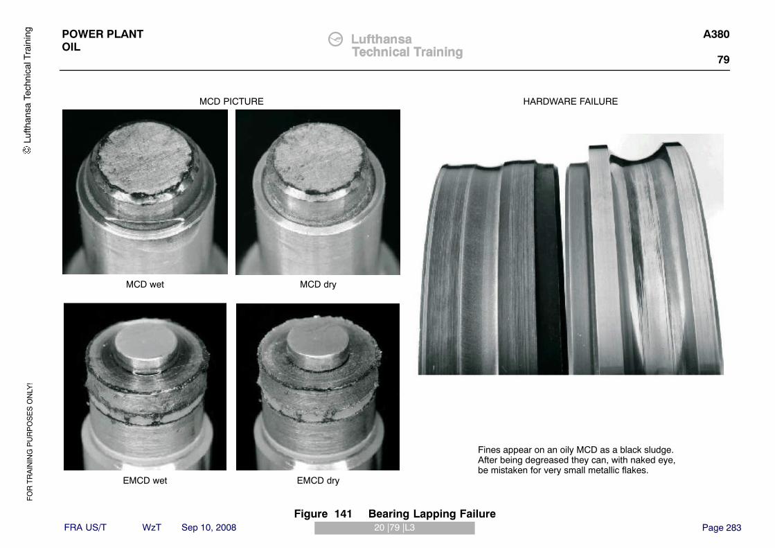
FO
R T
RA
ININ
G P
UR
PO
SE
S O
NLY
!
Page 28320 |79 |L3
POWER PLANTOIL
A380
79
FRA US/T WzT Sep 10, 2008
MCD PICTURE HARDWARE FAILURE
Fines appear on an oily MCD as a black sludge. After being degreased they can, with naked eye,be mistaken for very small metallic flakes.
MCD wet MCD dry
EMCD wet EMCD dry
Lufth
ansa
Tec
hnic
al T
rain
ing
Figure 141 Bearing Lapping Failure

FO
R T
RA
ININ
G P
UR
PO
SE
S O
NLY
!
Page 28420 |79 |L3
POWER PLANTOIL
A380
79
FRA US/T WzT Sep 10, 2008
MCD PICTURE HARDWARE FAILURE
The gear scuffing shown produces relatively coarse fines.
Note: normal „wear“ fines are similar in size to those produced by bearing lapping failures.
Lufth
ansa
Tec
hnic
al T
rain
ing
Figure 142 Gear Wear - Fines

FO
R T
RA
ININ
G P
UR
PO
SE
S O
NLY
!
Page 28520 |79 |L3
POWER PLANTOIL
A380
79
FRA US/T WzT Sep 10, 2008
MCD
EMCD
MCD PICTURE HARDWARE FAILURE
RACE
BALL
These can be sub-divided into ball bearing , roller bearing, bearing trackand gear teeth flakes.
• Ball bearing and ball bearing track flakes are usually roughly circular with radial splits
• Roller bearing and roller bearing track flakes can be roughly rectangular in shape with criss-cross scratches, but are usually similar to ball bearing flakes
• Fatique flakes are typically 0,5 - 1,0 mm (0.020 - 0.040 inch) in diameter, and very thin.
Lufth
ansa
Tec
hnic
al T
rain
ing
Figure 143 Bearing Failure - Flakes

FO
R T
RA
ININ
G P
UR
PO
SE
S O
NLY
!
Page 28620 |79 |L3
POWER PLANTOIL
A380
79
FRA US/T WzT Sep 10, 2008
MCD PICTURE HARDWARE FAILURE
Gear teeth fragments - corner pieces aof gear teeth may be evidence of
incorrect geatr alignement or bedding, or handling damage during over-haull.
Lufth
ansa
Tec
hnic
al T
rain
ing
Figure 144 Gear Tooth Fragments

FO
R T
RA
ININ
G P
UR
PO
SE
S O
NLY
!
Page 28720 |79 |L3
POWER PLANTOIL
A380
79
FRA US/T WzT Sep 10, 2008
Chip, ground surface
Chip, rough surface
MCD PICTURE HARDWARE FAILURE
Chips - these are very thick flakes or definite lumps of metal usullay with
one ground (smooth) surface.
Bearing race spalling can produce chips in addition to flakes.
Lufth
ansa
Tec
hnic
al T
rain
ing
Figure 145 Chips

FO
R T
RA
ININ
G P
UR
PO
SE
S O
NLY
!
Page 28820 |79 |L3
POWER PLANTOIL
A380
79
FRA US/T WzT Sep 10, 2008
MCD PICTURE HARDWARE FAILURE
Note: there may be criteria for the number of rivets found.
Refer to Aircraft Maintenance Manual.
Lufth
ansa
Tec
hnic
al T
rain
ing
Figure 146 Cage Rivet Failure

FO
R T
RA
ININ
G P
UR
PO
SE
S O
NLY
!
Page 28920 |79 |L3
POWER PLANTOIL
A380
79
FRA US/T WzT Sep 10, 2008
MCD PICTURE HARDWARE FAILURE
If cage tanges are found, refer to the Aircraft Maintenance Manual or a
local Rolls-Royce Service representative.
Lufth
ansa
Tec
hnic
al T
rain
ing
Figure 147 Roller Bearing Cage Tang Failure

FO
R T
RA
ININ
G P
UR
PO
SE
S O
NLY
!
Page 29020 |79 |L3
POWER PLANTOIL
A380
79
FRA US/T WzT Sep 10, 2008
Hairs of seal lining meterialor seal fin material
Chunks of lining orseal fin material
Explanation
While every effort is made to remove manufacturing orbuild debris (swarf), unfortunately small amounts maybe present within the engine on build. This beris will bewashed down by oil system to the MCD‘s.
Pieces of tuning are easily identifiable but milling de-bris, ehrn broken up, could possibly be confused withgear or steel rubbings and must be carfully examined.
In assition there may be some running-in or bedding-inof the engine which may produce a small amount ofadditional debris. Both will reduce after a short period oftime.
Seal lining material is sometimes released from thebearing chamber oil seal into the system after enginesurges.
Lufth
ansa
Tec
hnic
al T
rain
ing
Figure 148 Build Debris or Swarft

FO
R T
RA
ININ
G P
UR
PO
SE
S O
NLY
!
Page 29120 |79 |L3
POWER PLANTOIL
A380
79
FRA US/T WzT Sep 10, 2008
(E)MCD
debris
discovered
Analyse debris usingvisual and (optional)
SEM processes
Compare analysis against AircraftMaintenance Manual acceptance criteria.
Acceptable?
Inspect all MCD‘s fitted, scavenge screens and oilfilters. Compare against Aircraft
Maintenance Manual acceptance citeria.
Acceptable?
Fit diagnostic MCD‘s in all positions. Carry out a ground run or two, 90 second dry motor cycles
Indicate an alertr status an accumulated records andrequest MCD inspections to be taken at more
frequent intervals
Does debris rate reduce?
Remove engine fromservice immediately for
investigation
Resume normalmonitoring procedure
Yes
No
No
No
Yes
Yes
Lufth
ansa
Tec
hnic
al T
rain
ing
Figure 149 Action to take when debris is discovereed

FO
R T
RA
ININ
G P
UR
PO
SE
S O
NLY
!
Page 29221 |79 |L3
POWER PLANTOIL
A380
79
FRA US/T WzT Sep 10, 2008
PRESERVATION OF MAIN LINE BEARINGS
Reason for the JobUsed oil can cause corrosion if you keep an engine in storage for a long period.The preservation procedure makes it necessary to drain all the oil from the oilsystem. You must then supply new engine oil to the bearings. It is necessary tomotor the engine to move the oil through the system. This can only be donewith the engine installed or on a test bed.
ProcedureThe procedure is fully described in AMM Task 71−00−00−600−805 but can bebriefly described as follows:� Gain access to the engine� Drain the oil tank� Drain the oil from the fuel/oil heat exchanger� Drain the external gearbox� Drain the oil pressure filter housing� Drain the oil scavenge filter housing� Drain the oil pump assembly� Fill the engine oil tank with clean approved oil� Dry motor the engine until you see an oil pressure indication on the ECAM
display screen.� If there is not an oil pressure indication after 30 secs after N3 starts to turn,
stop the dry motor and carry out the following step.− Make sure you see oil in the oil tank sight glass− If necessary put oil in the tank until you can see oil in the sight glass− Repeat the dry motor of the engine until you see an oil pressure
indication on the ECAM display screen.− Put the aircraft back to its initial configuration.
Lufth
ansa
Tec
hnic
al T
rain
ing

FO
R T
RA
ININ
G P
UR
PO
SE
S O
NLY
!
Page 29321 |79 |L3
POWER PLANTOIL
A380
79
FRA US/T WzT Sep 10, 2008
Lufth
ansa
Tec
hnic
al T
rain
ing
Figure 150 Preservation of Main Line Bearings

FO
R T
RA
ININ
G P
UR
PO
SE
S O
NLY
!
Page 29401 |80 |L3
POWER PLANTSTARTING
A380
80
FRA US/T WzT Sep 10, 2008
ATA 80 STARTING
ENGINE STARTING SYSTEM
IntroductionThe EEC is able to perform Automatic and Manual engine starts initiated bydigital command signals from the aircraft AFDX system.To achieve engine starting, the following sub−systems are combined:� Starting� Fuel� Ignition
Each channel of the EEC interfaces with the Start Control Valve (SCV), theHeigh Energy Igniter Unit (HEIU) / systems and the minimum pressure andshut−off valve (MPSOV), in order to control their operation during thestarting/cranking phases.The EEC controls the engine starting sequences, engine cranking options andthe ignition selection in response to aircraft command signals.
Lufth
ansa
Tec
hnic
al T
rain
ing

FO
R T
RA
ININ
G P
UR
PO
SE
S O
NLY
!
Page 29501 |80 |L3
POWER PLANTSTARTING
A380
80
FRA US/T WzT Sep 10, 2008
e. g. Engine #2
Lufth
ansa
Tec
hnic
al T
rain
ing
Figure 151 Starting System Schematic

FO
R T
RA
ININ
G P
UR
PO
SE
S O
NLY
!
Page 29602 |80 |L3
POWER PLANTSTARTING
A380
80
FRA US/T WzT Sep 10, 2008
ENGINE STARTING COMMAND CONTROLS
Cockpit Starting/Shutdown/Ignition ControlsEngine starting, cranking and ignition selection are commanded from theaircraft cockpit panels. Engine cranking and starting is initiated by the EECbased on the position of the switches on the aircraft cockpit panels. Theseswitch positions are transmitted to the EEC via the aircraft Avionics Full DuplexSwitched Ethernet (AFDX).
Engine Control PanelThe engine control panel is located on the central pedestal in the cockpit andcomprises:1. Four Master Levers, one per engine each with two positions:
A. Engine ONB. Engine OFF
2. One Rotary Selector (which serves all four engines) with three positions:A. CrankB. NormalC. Ignition/Start
Engine Manual Start Push−buttonThe engine manual start push−buttons are located on the overhead panel ofthe cockpit. There is one guarded push−button for each engine.
Auto & Manual StartingFor automatic engine starts, only the Master Lever (one per engine) and RotarySwitch are used. For manual (alternate) engine starts, the Manual Start pushbutton is used as well as the Master Lever and Rotary Switch.Hardwired Master Lever position discrete signals are also available to the EEC.If the aircraft is in flight and the Rotary Switch position is invalid the EEC willinitiate an auto relight if the Master Lever is toggled from OFF to ON.
Lufth
ansa
Tec
hnic
al T
rain
ing

FO
R T
RA
ININ
G P
UR
PO
SE
S O
NLY
!
Page 29702 |80 |L3
POWER PLANTSTARTING
A380
80
FRA US/T WzT Sep 10, 2008
Lufth
ansa
Tec
hnic
al T
rain
ing
Figure 152 Cockpit Panels

FO
R T
RA
ININ
G P
UR
PO
SE
S O
NLY
!
Page 29803 |80 |L3
POWER PLANTSTARTING
A380
80
FRA US/T WzT Sep 10, 2008
COCKPIT INDICATION
During the start sequence, the nacelle temperature indications are replaced bythe ignition and starting parameters on the System Display (SD).The start parameters displayed are as follows:� Ignition (A, B or AB).� Start control valve position.� Air pressure to the starter.
Lufth
ansa
Tec
hnic
al T
rain
ing

FO
R T
RA
ININ
G P
UR
PO
SE
S O
NLY
!
Page 29903 |80 |L3
POWER PLANTSTARTING
A380
80
FRA US/T WzT Sep 10, 2008
Lufth
ansa
Tec
hnic
al T
rain
ing
Figure 153 Engine Staring Indications

FO
R T
RA
ININ
G P
UR
PO
SE
S O
NLY
!
Page 30004 |80 |L3
POWER PLANTSTARTING
A380
80
FRA US/T WzT Sep 10, 2008
STARTER CONTROL VALVE (SCV)
PurposeThe starter control valve (SCV) controls the air supply to the starter motor.
LocationThe starter control valve is installed in the starter duct at the lower left side ofthe fan case. Access by opening the left fan cowl door.
OperationOn command from the EEC, the pneumatic starter control valve, controls theflow of air to the pneumatic starter. During the starting sequence the pneumaticstarter control valve is commanded closed after the starter has reached cut−outspeed.A solenoid−operated valve and regulator control the supply of starter air ductpressure to an actuator that moves the butterfly valve. The solenoid contains adouble coil assembly that is controlled by the EEC, one coil being connected toEEC channel A, the other to EEC channel B. The regulator limits the pressureof air to the pneumatic starter.Two microswitches give an indication to the EEC of the valve position. Onemicroswitch is connected to EEC channel A, the other to EEC channel B.
Manual OperationAn extension of the butterfly valve shaft has a visual position indicator and asquare socket to permit manual operation of the butterfly valve. Access to thesquare drive is via a sprung loaded flap in the fan cowl door. Manual operationof the pneumatic start control valve does not require the fan cowl door to beopened. This method can be used to dispatch the aircraft with a fault in theSCV system.
Failure of SCVFailure of the pneumatic starter control valve to close, or leakage of the starterair ducting, is determined by commanded valve position and a flow detectionsystem in the start air ducting. When a failure is detected the engine cabinbleed and aircraft cross−flow valves are closed to prevent an overspeed of thepneumatic starter or leakage of air into Zone 1.
Lufth
ansa
Tec
hnic
al T
rain
ing

FO
R T
RA
ININ
G P
UR
PO
SE
S O
NLY
!
Page 30104 |80 |L3
POWER PLANTSTARTING
A380
80
FRA US/T WzT Sep 10, 2008
Lufth
ansa
Tec
hnic
al T
rain
ing
Figure 154 Start Control Valve

FO
R T
RA
ININ
G P
UR
PO
SE
S O
NLY
!
Page 30205 |80 |L3
POWER PLANTSTARTING
A380
80
FRA US/T WzT Sep 10, 2008
STARTER MOTOR
PurposeThe pneumatic starter motor turns the external gearbox for starting andmotoring the engine. The external gearbox turns the high−pressure shaft (N3).
LocationThe starter motor is located on the left side front face of the external gearbox.Access by opening the left fan cowl.
DescriptionThe pneumatic starter motor consists of:� Inlet housing with containment baffles� Turbine rotor assembly� Reduction gears� Gear cage� A clutch� Transmission housing� Splined output shaft
The inlet housing is designed to lessen the danger of turbine blades exiting thestarter in the event of a turbine rotor assembly failure. A quick attach−detach(QAD) clamp attaches the starter motor to a QAD adapter, which is bolted tothe front face of the external gearbox. Dowels between the starter and adapterensure correct alignment of the starter motor.
Functional DescriptionThe air supply from the starter air duct turns the turbine at high speed with lowtorque. The reduction gears reduce the speed and increase torque to the clutchmechanism and output shaft. After passing through the turbine the air isreleased to ambient through the exhaust deflector baffles. The clutchmechanism (SEC) disengages the starter from the engine once the enginereaches idle speed.
Starter Oil SystemThe starter motor has a self−contained oil system with the following parts:� Gravity fill and overflow plug� Oil sight glass� Drain plug with an integral magnetic chip detector (MCD)
The MCD catches ferrous contamination in the starter oil system. To inspectthe MCD, unscrew from the drain plug housing and remove.
Lufth
ansa
Tec
hnic
al T
rain
ing

FO
R T
RA
ININ
G P
UR
PO
SE
S O
NLY
!
Page 30305 |80 |L3
POWER PLANTSTARTING
A380
80
FRA US/T WzT Sep 10, 2008
Lufth
ansa
Tec
hnic
al T
rain
ing
Figure 155 Starter Motor

FO
R T
RA
ININ
G P
UR
PO
SE
S O
NLY
!
Page 30406 |80 |L2
POWER PLANTSTARTING
A380
80
FRA US/T WzT Sep 10, 2008
STARTER OIL SERVICING
(AMM 80−11−41)The starter servicing procedure is detailed in the AMM 80−11−41 and brieflydescribed below:
WARNING: DO NOT LET ENGINE OIL STAY ON YOUR SKIN.POISONOUS MATERIALS CAN BE ABSORBED THROUGHYOUR SKIN.
CAUTION: REMOVE ANY OIL SPILLAGE ON THE ENGINEIMMEDIATELY WITH A LINT FREE CLOTH AS THE OIL MAYCAUSE DAMAGE TO THE SURFACE PROTECTION ORSOME ENGINE PARTS.
Procedure� Open the fan cowl doors.� Remove the drain plug and allow the oil to drain from the starter� Install a new seal ring on the drain plug and install the drain plug, torque
tighten and safety.� Remove the oil fill and overflow plugs from the starter and discard the seals.� Add clean oil to the starter oil fill position until oil starts to drip from the oil
level overflow.� Wait until oil does not drip from the oil level overflow.� Remove oil from the external surface of the starter with a clean cloth� Put new seal rings on the plugs and install the oil fill and overflow plugs,
torque tighten and safety.� Look at the oil level sightglass and make sure the level is above the ADD
mark.
Detailed Inspection of the Starter MCD (AMM 80−11−41)The inspection of the Starter MCD is detailed the AMM 80−11−41 and brieflydescribed below:Note: The magnetic chip detector is installed through the center of the drainplug. Do not remove the drain plug.
Procedure:� Remove the MCD plug and allow the oil to drain from the starter� Put the MCD in clean Kerosene and remove the oil. The Kerosene must be
in a clean non−metallic container.� Examine the MCD in good light for contamination. If the MCD has chips
larger than 0.1 in (2.54 mm) in one direction is found, reject the starter.� Keep any contamination which you find as this will help you to keep a record
of type of wear in the starter.� If you reject the starter, send the contamination which you found with the
starter to the service bay.
Lufth
ansa
Tec
hnic
al T
rain
ing

FO
R T
RA
ININ
G P
UR
PO
SE
S O
NLY
!
Page 30506 |80 |L2
POWER PLANTSTARTING
A380
80
FRA US/T WzT Sep 10, 2008
Lufth
ansa
Tec
hnic
al T
rain
ing
Figure 156 Starter Oil Servicing

FO
R T
RA
ININ
G P
UR
PO
SE
S O
NLY
!
Page 30601 |74 |L3
POWER PLANTIGNITION
A380
74
FRA US/T WzT Sep 10, 2008
ATA 74 IGNITION
ENGINE IGNITION SYSTEM
PurposeEach engine has two ignition systems, “1“ and “2“, which can operate togetheror independently to supply electrical sparks in the combustion chamber toignite the fuel/air mixture or keep combustion going.
LocationThe ignition units are located on the lower left side of the fan case, rear unit(system “1“) and front unit (system “2“). Access through left fan cowl. The twoigniter plugs fit through the outer combustion case.
DescriptionEach engine has two ignition systems, which can operate independently ortogether. Each system has an ignition power supply and an ignition distributionsystem. The ignition systems are operated when supplied with 115 V AC(variable frequency) aircraft power by the EECThe engine master lever must be in the “ON“ position for supply of ignitionelectrical power.EEC logic is also used to operate the ignition systems when inclement weatheris detected at low power or there is an un−commanded engine run down:� Automatic inclement weather protection (continuous ignition)� Auto relight function
Continuous ignition is only used when commanded by the EEC for automaticinclement weather protection, there is no manual selection of continuousignition.
Ignition SelectionThe EEC alternates between the ’1’ and ’2’ ignition systems for Automaticengine ground starts. In the event of a “failure to light“ being detected usingone system, the EEC automatically commands both ignition systems to operateand sends an “ignition failed“ message to the aircraft identifying the inoperativecomponents.The EEC commands both ignition systems to operate for:� manual ground starts� in−flight starts� automatic inclement weather protection (continuous ignition)� auto relight.
Quick RelightIf the master lever is accidentally moved to the OFF position during engineoperation and subsequently returned to the ON position within 30 seconds, theEEC will command both ignition systems to operate until 10 seconds after theengine reaches idle providing:� The HP shaft speed is above 10% when the master lever is returned to the
ON position when in flight� The HP shaft speed is above 50% when the master lever is returned to the
ON position when on the ground.
Lufth
ansa
Tec
hnic
al T
rain
ing

FO
R T
RA
ININ
G P
UR
PO
SE
S O
NLY
!
Page 30701 |74 |L3
POWER PLANTIGNITION
A380
74
FRA US/T WzT Sep 10, 2008
Lufth
ansa
Tec
hnic
al T
rain
ing
Figure 157 Ignition System Schematic

FO
R T
RA
ININ
G P
UR
PO
SE
S O
NLY
!
Page 30802 |74 |L3
POWER PLANTIGNITION
A380
79
FRA US/T WzT Sep 10, 2008
IGNITION SYSTEM COMPONENTS
Ignition UnitThe ignition unit is a capacitive discharge circuit. The unit converts the 115 VAC variable frequency aircraft power supply input to provide an output voltageof approximately 3 kV. Energy is stored in the ignition unit at 7.5 − 12.0 Joulesand released by the unit to give a spark to the igniter plug at a minimum rate of60 sparks per minute.There is no BITE within the ignition unit. The EEC monitors supply of power tothe ignition unit to enable faults to be annunciated and to allow automaticselection of the other ignition system.
Igniter PlugThe igniter plug is a surface discharge type and is used to ignite the fuel / airmixture in the combustion chamber. The igniter plugs are installed adjacent tothe fuel spray nozzles at position numbers eight (system 1) and twelve (system 2) when the engine is viewed clockwise from the rear.
Ignition LeadThe ignition leads connect the ignition units to the igniter plugs and havereplaceable contact buttons at both ends.The ignition lead from the igniter plug located adjacent to the number eight fuelspray nozzle is connected to the rear ignition unit (system 1) and the igniterlead from the igniter plug adjacent to the number twelve fuel spray nozzle isconnected to the front ignition unit (system 2).
Lufth
ansa
Tec
hnic
al T
rain
ing

FO
R T
RA
ININ
G P
UR
PO
SE
S O
NLY
!
Page 30902 |74 |L3
POWER PLANTIGNITION
A380
79
FRA US/T WzT Sep 10, 2008
Lufth
ansa
Tec
hnic
al T
rain
ing
Figure 158 Ignition System Components

FO
R T
RA
ININ
G P
UR
PO
SE
S O
NLY
!
Page 31003 |74 |L3
POWER PLANTIGNITION
A380
74
FRA US/T WzT Sep 10, 2008
IGNITION SYSTEM DESCRIPTION
Ignition Power SupplyThe ignition system 1 and ignition system 2 use power from the 115VACEmergency (Ignition) and 115VAC Normal (Ignition) electrical busesrespectively.The EEC switches the supply of electrical power to each ignition box. When incontrol, each channel can command both electrical power switches, even whenthe other channel processor system is faulty. The EEC incorporates a powermonitor in each electrical power supply output to the ignition box.The ignition boxes, when supplied with 115VAC convert and output this powerto the high tension supply to their respective surface discharge Ignition Plugs.The engine electrical ground plane provides the high tension power returnpatch.
Single & Dual Ignition SelectionThe ignition system may be required by a number of functions, with a primarychoice of single or dual ignition circuit operation according to the table opposite.To optimise the life of the ignition system (especially ignition plugs) andminimise the risk of operation with dormant faults, the EEC will normallycommand single ignition circuit operation for ground Autostart.The cycle of ignition circuit operations, during ground autostart, is shown on thetable opposite. This will exercise all software controlled combinations of EECchannel in control, ignition exciter, lead and plug and power source to exposeotherwise dormant faults.
Lufth
ansa
Tec
hnic
al T
rain
ing

FO
R T
RA
ININ
G P
UR
PO
SE
S O
NLY
!
Page 31103 |74 |L3
POWER PLANTIGNITION
A380
74
FRA US/T WzT Sep 10, 2008
Lufth
ansa
Tec
hnic
al T
rain
ing
Figure 159 Ignition System Selection

FO
R T
RA
ININ
G P
UR
PO
SE
S O
NLY
!
Page 31204 |74 |L3
POWER PLANTIGNITION
A380
79
FRA US/T WzT Sep 10, 2008
REPLACEMENT OF THE IGNITION LEAD CONTACTS
Removal of the Ignition Lead ContactsThis task is covered in AMM Task 74−21−52−000−802
WARNING: YOU MUST ISOLATE THE ELECTRICAL POWER SUPPLY ATLEAST 3 MINUTES BEFORE YOU WORK ON THE IGNITIONSYSTEM. THIS WILL LET THE SYSTEM VOLTAGEDECREASE. THE IGNITION SYSTEM USES VERY HIGHVOLTAGES WHICH ARE DANGEROUS. THE ELECTRICALPOWER IS SUFFICIENTLY STRONG TO CAUSE AN INJURYOR KILL YOU.
Make sure you observe all the Warnings in the AMM procedure.� Disconnect the electrical input lead connector from the ignition system you
are going to work on.� Put a blanking cap on the disconnected connector.
CAUTION: YOU MUST NOT BEND THE IGNITION LEADS TOO MUCHWHEN YOU DISCONNECT/CONNECT THEM. THE IGNITIONLEADS CAN BE DAMAGED AND CAUSE ELECTRICALCIRCUIT DEFECTS.
� Remove and discard the lockwire and disconnect the ignition lead connectorfrom the applicable ignition unit.
� Remove and discard the lockwire and disconnect the ignition lead connectorfrom the applicable igniter plug.
� Using pliers, remove the locating ring.� Remove the ceramic insulator� Remove the contact from the contact body� Put blanking caps on the ignition unit, igniter plug and ignition lead.
Installation of the Ignition Lead ContactsThis task is covered in AMM Task 74−21−52−400−802Make sure you observe all the Warnings in the AMM procedure.� Remove the blanking caps from the ignition lead� Install the contact in the contact body� Install the ceramic insulator on the contact body� Attach the insulator with the locating ring� Connect the ignition lead connector to the applicable ignition unit� Torque the connector and safety with lockwire or safety cable.� Connect the ignition lead connector to the applicable igniter plug� Torque the connector and safety with lockwire or safety cable.� Connect the electrical input lead connector on the ignition unit� Do a test of the Ignition System.
Lufth
ansa
Tec
hnic
al T
rain
ing

FO
R T
RA
ININ
G P
UR
PO
SE
S O
NLY
!
Page 31304 |74 |L3
POWER PLANTIGNITION
A380
79
FRA US/T WzT Sep 10, 2008
Lufth
ansa
Tec
hnic
al T
rain
ing
Figure 160 Ignition Lead Contact Replacement

FO
R T
RA
ININ
G P
UR
PO
SE
S O
NLY
!
Page 31405 |74 |L3
POWER PLANTIGNITION
A380
79
FRA US/T WzT Sep 10, 2008
IGNITER INSPECTION
(AMM 74−21−51−200−801)
WARNING: YOU MUST ISOLATE THE ELECTRICAL POWER SUPPLY ATLEAST 3 MINUTES BEFORE YOU WORK ON THE IGNITIONSYSTEM. THIS WILL LET THE SYSTEM VOLTAGEDECREASE. THE IGNITION SYSTEM USES VERY HIGHVOLTAGES WHICH ARE DANGEROUS. THE ELECTRICALPOWER IS SUFFICIENTLY STRONG TO CAUSE AN INJURYOR KILL YOU.
Observe all AMM WarningsExamine the igniter plug for the following damage:� Examine the igniter plug body, the joints and the igniter plug insulation
above the contact button for cracks. If cracked, reject.� Frettage in the outer shell of the igniter plug. See AMM for limits.� Examine the igniter tip for erosion. See AMM for limits.� Examine the contact button for damage. If damaged, reject.
NOTE: If excessive contact pitting can be seen due to arcingimpingement, reject.
NOTE: If excessive contact pitting can be seen, examine the ignitionlead contact for excessive pitting. If excessive pitting can beseen, replace the ignition lead contact.
� If the igniter is corroded and/or pitted, reject.
NOTE: The igniter body has a rough surface when new.� Examine the plug center electrode. If the center electrode is not there,
reject. If rejected, make an inspection of the HP turbine blades.� Examine the insulator (between the center and outer electrode) for cracks
or missing pieces. If it is cracked or has missing pieces, reject.
Lufth
ansa
Tec
hnic
al T
rain
ing

FO
R T
RA
ININ
G P
UR
PO
SE
S O
NLY
!
Page 31505 |74 |L3
POWER PLANTIGNITION
A380
79
FRA US/T WzT Sep 10, 2008
Lufth
ansa
Tec
hnic
al T
rain
ing
Figure 161 Igniter Inspection

FO
R T
RA
ININ
G P
UR
PO
SE
S O
NLY
!
Page 31606 |74 |L3
POWER PLANTIGNITION
A380
79
FRA US/T WzT Sep 10, 2008
IGNITER PLUG REPLACEMENT
IGNITER REMOVAL (AMM 74−21−51−000−801)
WARNING: YOU MUST ISOLATE THE ELECTRICAL POWER SUPPLY ATLEAST 3 MINUTES BEFORE YOU WORK ON THE IGNITIONSYSTEM. THIS WILL LET THE SYSTEM VOLTAGEDECREASE. THE IGNITION SYSTEM USES VERY HIGHVOLTAGES WHICH ARE DANGEROUS. THE ELECTRICALPOWER IS SUFFICIENTLY STRONG TO CAUSE AN INJURYOR KILL YOU.
Observe all AMM Warnings
Procedure:� On the OMT, get access to the Power Distribution Control management
pages and open & safety the applicable circuit breakers.� If working on an inboard engine, make sure the thrust reverser is
deactivated.� Open the fan cowls and fan exhaust cowls� Disconnect the applicable electrical input lead connector on the ignition unit
and cap the connector� Remove the lockwire and disconnect the applicable ignition lead from the
igniter plug and cap the connector.� Use HU43915 (socket) to remove the igniter plug and install blanking caps
on the plug and opening.
IGNITER INSTALLATION (AMM 74−21−51−400−801)Observe all safety Warning & Cautions
Procedure� Apply anti−seize compound (Omat 4−62) to the threads of the igniter plug� Use HU43915 (socket) to install the igniter plug and torque to the value
given in the AMM
NOTE: It is not necessary to carry out an immersion depth check wheninstalling an igniter. The adjusting shims are located between theadapter and outer case and these are not removed during igniterplug replacement.
� Clean the contact buttons with emery paper (Omat 5−43). Remove the dustwith a lint free cloth
� Connect the ignition lead to the igniter plug, torque and safety� Connect the applicable electrical input lead connector to the ignition unit� Reset the applicable circuit breakers� Carry out a test of the Ignition system
Lufth
ansa
Tec
hnic
al T
rain
ing
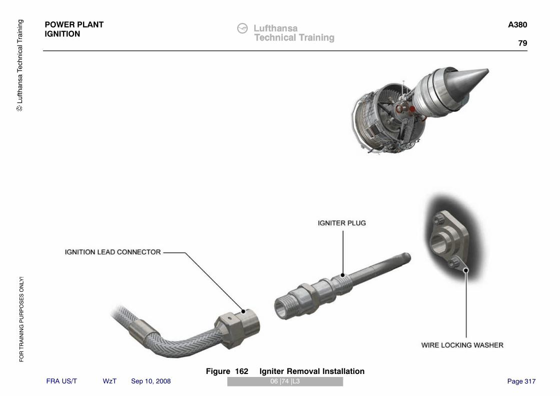
FO
R T
RA
ININ
G P
UR
PO
SE
S O
NLY
!
Page 31706 |74 |L3
POWER PLANTIGNITION
A380
79
FRA US/T WzT Sep 10, 2008
Lufth
ansa
Tec
hnic
al T
rain
ing
Figure 162 Igniter Removal Installation

FO
R T
RA
ININ
G P
UR
PO
SE
S O
NLY
!
Page 31801 |78 |L2
POWER PLANTEXHAUST
A380
78
FRA US/T WzT Sep 10, 2008
ATA 78−30 THRUST REVERSER
TRENT 900 NACELLE OVERALL PRESENTATIONThe nacelle is the aerodynamic structure around the engine.
The primary functions of the nacelle :� Ensure smooth airflow both around and into the engine� Protect the engine and the engine accessories� Provide engine noise attenuation� Permit access to the engine & its components for servicing and
maintenance� Reverse engine fan flow after landing to brake aircraft� Provide ventilation of the engine fan and core zones� Participate to engine load distribution (load sharing)
The TRENT900 nacelle is composed of :� Air Intake Cowl� Fan Cowl Doors� Thrust Reverser Cowl Doors only for inboard engines.� Electronic Thrust Reverser Actuation System, mounted on the Thrust
Reverser forward frame.� Fan Exhaust Cowls for outboard engines� Exhaust Nozzle and Plugs (rear and forward)
Lufth
ansa
Tec
hnic
al T
rain
ing

FO
R T
RA
ININ
G P
UR
PO
SE
S O
NLY
!
Page 31901 |78 |L2
POWER PLANTEXHAUST
A380
78
FRA US/T WzT Sep 10, 2008
TRENT 900 Engine
Thrust Reverser
or
Fan Exhaust Cowl
Pylon
Exhaust Nozzle
Exhaust Plugs
Fan Cowl Door
Air Intake Cowl TRENT 900 Engine
Lufth
ansa
Tec
hnic
al T
rain
ing
Figure 163 Trent 9000 Nacelle Overalll Presentation

FO
R T
RA
ININ
G P
UR
PO
SE
S O
NLY
!
Page 32002 |78 |L3
POWER PLANTEXHAUST
A380
78
FRA US/T WzT Sep 10, 2008
THRUST REVERSER COWL DOORS
Thrust Reverser Cowl Doors PresentationThe A380 inboard engines are equipped with Thrust Reverser Cowl Doors.(Outboard engines are equipped with Fan Exhaust Cowls.The main function of the Thrust Reverser is to contribute to the aircraft brakingat landing.The Thrust Reverser assembly encloses the engine core with an aerodynamicflow path, and provides a fan exhaust duct and nozzle exit.The Thrust Reverser assembly is located between the Fan Cowl Doors and theExhaust. It is attached to the wing pylon by four hinges. Two hinges areattached to floating rods.The Thrust Reverser assembly is a cascade type Thrust Reverser withtranslating cowls and blocker doors.It is made of two halves that make a duct around the engine core. Each halfconsists of a fixed structure, which provides support for the cascades andactuation system, and a translating cowl.The Thrust Reverser halves open at 6 o’clock and rotates around the 12o’clock hinge beam to give access to the engine during maintenanceoperations.The Thrust Reverser system is composed of :� the structure� the Powered Cowl Opening System� the control and indicating : the ETRAS (Electronic Thrust Reverser
Actuation Controller)
Thrust Reverser Cowl Doors StructureThe Thrust Reverser structure is composed of a fixed structure (outer andinner fixed structure) and the translating cowl.
FIXED STRUCTURE
Outer Fixed Structure AssemblyThe outer fixed structure assembly is composed of the following components:� the forward frame� the J−ring� the cascades assembly (12 cascades)
Inner Fixed Structure AssemblyThe inner fixed structure assembly is composed of the following components:� the 12 o’clock hinge beam� the 6 o’clock latch beam� the Inner Fixed Structure (IFS)
TRANSLATING STRUCTUREThe translating structure is composed of the following components:� the translating cowl (including two translating sleeves),� the blocker doors and links (six for each translating cowl).
Lufth
ansa
Tec
hnic
al T
rain
ing

FO
R T
RA
ININ
G P
UR
PO
SE
S O
NLY
!
Page 32102 |78 |L3
POWER PLANTEXHAUST
A380
78
FRA US/T WzT Sep 10, 2008
CASCADES 12 POSITIONS
J-RING
INNER FIXED STRUCTURE
TRANSLATING COWL
LINKS(6 POSITIONS)
BLOCKER DOORS(6 POSITIONS)
PRECOOLERSCOPE TCC INLET
FINGERSEALS
BLEED VALVES
Weight: 650 kg (1 430 lbs) per Cowl Door
Lufth
ansa
Tec
hnic
al T
rain
ing
Figure 164 Thrust Reverser Cowl Doors

FO
R T
RA
ININ
G P
UR
PO
SE
S O
NLY
!
Page 32203 |78 |L3
POWER PLANTEXHAUST
A380
78
FRA US/T WzT Sep 10, 2008
FAN EXHAUST COWLThis component is dedicated to be installed on the utboard nacelles inreplacement of the Thrust Reversers.The Fan Exhaust Cowls (FEC) therefore share the same external interfaces asthe Thrust Reverser.It differs from the Thrust Reverser Cowl Doors by :� No ETRAS� No blocker doors and links� No translating structure� No latch L8� Carrying a Core Pressure Relief Door
If the Core Pressure Relief Door is opened, the red popout goes out and isvisible from the ground.
Lufth
ansa
Tec
hnic
al T
rain
ing

FO
R T
RA
ININ
G P
UR
PO
SE
S O
NLY
!
Page 32303 |78 |L3
POWER PLANTEXHAUST
A380
78
FRA US/T WzT Sep 10, 2008
No ETRAS
Weight: 380 kg (840 lbs) per Cowl
No Latch L8No Blocker DoorsNo LinksNo Translating Structure
Pressure Relief Doors
(left side)
View from internal side
Pop Out
View from external side
Lufth
ansa
Tec
hnic
al T
rain
ing
Figure 165 Fan Exhaust Cowl

FO
R T
RA
ININ
G P
UR
PO
SE
S O
NLY
!
Page 32404 |78 |L2
POWER PLANTEXHAUST
A380RR Trent 900
78
FRA US/T WzT Sep 10, 2008
FAN EXHAUST COWL/THRUST REVERSER COWL
OpeningThe fan exhaust cowl / thrust reverser cowl doors can be opened formaintenance purposes on the engine. The unlatching sequence is carried outfrom the latch access door and the latches all installed at the bottom of the fanexhaust cowl / thrust reverser cowl. Unlocking of these latches is done in adefined sequence:� the Latch L1 is opened first by pulling the lock trigger and the handle to the
down position,� the Latch L6.1 handle has to be fully open,� the Latch L6.2,
NOTE: A push/pull cable connects the latch L6.1 to the latch L7. Whenyou unlatch the latch L6.1, you unlatch the latch L7 at the sametime.
� the Latch L5.2� the Latch L5.1,� the Latch L4,� the Latch L3,� the Latch L2.
Once the fan exhaust cowl / thrust reverser cowl doors are unlocked, theopening is done from the switch box. There is one switch box per side. Themaintenance personnel must push the UP switch until the fan exhaust cowl /thrust reverser cowl door is opened and the HOR is locked. When the HOR islocked, the green stripe is visible. Then the maintenance personnel must pushthe DOWN switch to hold the fan exhaust cowl / thrust reverser cowl on theHOR. The fan exhaust cowl / thrust reverser cowl doors have two openpositions:� initial position of 35 degrees,� full open position of 45 degrees.
NOTE: To open the cowl up to 45 degrees, it must be open up to 35degrees before and hold open rod have to be put on its 45degrees fitting.
CAUTION: MAKE SURE THAT THE WIND SPEED CONDITIONS ARENOT MORE THAN 45 KNOTS.
CAUTION: BEFORE OPENING THE FAN EXHAUST COWLS / THRUSTREVERSER COWLS, MAKE SURE THAT SLATS ARERETRACTED AND THAT THEY CANNOT MOVE, TOPREVENT FROM POSSIBLE INTERFERENCES.
CAUTION: BEFORE OPENING THE FAN EXHAUST COWLS / THRUSTREVERSER COWLS OF INBOARD ENGINES (2 OR 3), MAKESURE THAT THE THRUST REVERSER SYSTEM HAS BEENDEACTIVATED FOR MAINTENANCE.
Lufth
ansa
Tec
hnic
al T
rain
ing

FO
R T
RA
ININ
G P
UR
PO
SE
S O
NLY
!
Page 32504 |78 |L2
POWER PLANTEXHAUST
A380RR Trent 900
78
FRA US/T WzT Sep 10, 2008
Lufth
ansa
Tec
hnic
al T
rain
ing
Figure 166 Fan Exhaust Cowl/Thrust Reverser Cowl − Opening

FO
R T
RA
ININ
G P
UR
PO
SE
S O
NLY
!
Page 32604 |78 |L2
POWER PLANTEXHAUST
A380RR Trent 900
78
FRA US/T WzT Sep 10, 2008
THIS PAGE INTENTIONALLY LEFT BLANK
Lufth
ansa
Tec
hnic
al T
rain
ing

FO
R T
RA
ININ
G P
UR
PO
SE
S O
NLY
!
Page 32704 |78 |L2
POWER PLANTEXHAUST
A380RR Trent 900
78
FRA US/T WzT Sep 10, 2008
Lufth
ansa
Tec
hnic
al T
rain
ing
Figure 167 Fan Exhaust Cowl/Thrust Reverser Cowl − CAUTION

FO
R T
RA
ININ
G P
UR
PO
SE
S O
NLY
!
Page 32805 |78 |L2
POWER PLANTEXHAUST
A380RR Trent 900
78
FRA US/T WzT Sep 10, 2008
Specific Latch for Inboard EnginesIn addition, the two fixed halves of the thrust reverser structures for the inboardengines are connected together by an eighth latch L8. The latch L8 iscomposed of a telescopic locking system permanently connected to the LHstructure at 12 o’clock and a pin latch at 6 o’clock position. A handle controlsthis latch, and locks/unlocks simultaneously the 6 o’clock pin latch via acommand rod and the 12 o’clock latch. The 12 o’clock latch is linked to the 6o’clock pin latch by the push/pull cable.To open the thrust reverser cowls, you must:� Turn counterclockwise the handle,� Pull the handle until the red strip becomes visible to unlock the latch L8,� Turn clockwise the handle.
To close the cowls, you must make sure that the latch L8 returned correctly inits stored position. You must also secure it by re−installing the safety ball pin.
NOTE: L8 is the first latch to be opened for the opening sequence of thethrust reverser cowl on the inboard engines.
Lufth
ansa
Tec
hnic
al T
rain
ing

FO
R T
RA
ININ
G P
UR
PO
SE
S O
NLY
!
Page 32905 |78 |L2
POWER PLANTEXHAUST
A380RR Trent 900
78
FRA US/T WzT Sep 10, 2008
Lufth
ansa
Tec
hnic
al T
rain
ing
Figure 168 Specific Latch for Inboard Engines

FO
R T
RA
ININ
G P
UR
PO
SE
S O
NLY
!
Page 33006 |78 |L3
POWER PLANTEXHAUST
A380
78
FRA US/T WzT Sep 10, 2008
The Hold Open Rod (HOR)Each Thrust Reverser Cowl Door opens and is maintained in the openedposition by one HOR.The other mean of retention is the cowl door opening actuator.Two opening positions : 35� and 45�.The HOR keeps the Thrust Reverser Cowl Door in the opened position forground maintenance.The ends of the HOR are attached to a fitting on the Thrust Reverser CowlDoor and to a bracket on the engine.The 35� fitting is the storage fitting.It is necessary to move the HOR on a second forward frame fitting to open theThrust Reverser Cowl Door in the 45� position.Coloured flags enable to know the HOR state :� red indicator : unlock� green indicator : lock
Lufth
ansa
Tec
hnic
al T
rain
ing

FO
R T
RA
ININ
G P
UR
PO
SE
S O
NLY
!
Page 33106 |78 |L3
POWER PLANTEXHAUST
A380
78
FRA US/T WzT Sep 10, 2008
Hold Open Rod in stored position
Hold Open Rod in 45°opened position
35° fitting
45° fitting
Lufth
ansa
Tec
hnic
al T
rain
ing
Figure 169 Hold Open Rod

FO
R T
RA
ININ
G P
UR
PO
SE
S O
NLY
!
Page 33207 |78 |L2
POWER PLANTEXHAUST
A380RR Trent 900
78
FRA US/T WzT Sep 10, 2008
Fan Exhaust Cowl/Thrust Reverser Cowl ClosingAt the end of maintenance tasks on the engine, the fan exhaust cowl / thrustreverser cowl doors have to be closed to put the aircraft back into operation.First of all, the maintenance personnel must push the UP switch to unload theHORs. The HOR is then unlocked and in this case, the red stripe is visible. TheDOWN switch must be pushed and held until the fan exhaust cowl / thrustreverser cowl door closes completely.
NOTE: You cannot close the cowl from the 45 degrees position to the 35degrees position directly. At 35 degrees, put the hold open rod onthe 35 degrees HOR fitting.
The locking of these latches is done in a defined sequence:� the Latch L2 first,� the Latch L3,� the Latch L4,� the Latch L5.1,� the lLatch L5.2,� the Latch L6.1 handle has to be fully closed,
NOTE: A push/pull cable connects the Latch L6.1 to the Latch L7. Whenyou latch the Latch L6.1, you latch the Latch L7 at the sametime.
� the Latch L6.2,� and at the end, the Latch L1 is closed by pulling the lock trigger and the
handle upward.Once the latches are locked, the latch access door has to be closed.
Lufth
ansa
Tec
hnic
al T
rain
ing

FO
R T
RA
ININ
G P
UR
PO
SE
S O
NLY
!
Page 33307 |78 |L2
POWER PLANTEXHAUST
A380RR Trent 900
78
FRA US/T WzT Sep 10, 2008
Lufth
ansa
Tec
hnic
al T
rain
ing
Figure 170 Fan Exhaust Cowl/Thrust Reverser Cowl − Closing

FO
R T
RA
ININ
G P
UR
PO
SE
S O
NLY
!
Page 33408 |78 |L2
POWER PLANTEXHAUST
A380RR Trent 900
78
FRA US/T WzT Sep 10, 2008
Manual Opening/ClosingEach fan exhaust cowl / thrust reverser cowl is equipped with an openingactuator, which has a MDU (Manual Drive Unit). This MDU can be used for theopening/closing of the fan exhaust cowl / thrust reverser cowl when theelectrical power is off, or in case of failure of the electrical functions in the cowlopening system. The fan exhaust cowl / thrust reverser cowl can be openmanually to 35 or 45 degrees.To open the fan exhaust cowl / thrust reverser cowl manually, you must:� Remove the MDU cap� Put the tool in the MDU 3/8” square� Use the tool to open the actuator to 35 degrees position (clockwise) until
HOR locking� Use the tool to release the weight of the cowl on the HOR
(counterclockwise)� To open the cowl to 45 degrees position, put the HOR on its 45 degrees
fitting, and use the tool to open the actuator to 45 degrees position(clockwise) until HOR locking
NOTE: The HOR makes a rattling noise at the locked position.� Use the tool to release the weight of the cowl on the HOR
(counterclockwise)� Remove the tool and reinstall the cap at the end.
NOTE: The HOR locking sleeve must slide to show the green stripe(locked position) and hide the red stripe.
CAUTION: IF POWERED TOOLS ARE USED, ONLY USE POWEREDTOOLS WITH A TORQUE LIMITER TO MAXIMUM VALUE133.5 IN.LBS (15 N.M).
CAUTION: TURN THE TORQUE WRENCH SLOWLY WHEN THE HOLDOPEN ROD IS NEAR THE LOCKED POSITION TO PREVENTDAMAGE TO THE HOLD OPEN ROD AND TO THE THRUSTREVERSER STRUCTURE.
Lufth
ansa
Tec
hnic
al T
rain
ing

FO
R T
RA
ININ
G P
UR
PO
SE
S O
NLY
!
Page 33508 |78 |L2
POWER PLANTEXHAUST
A380RR Trent 900
78
FRA US/T WzT Sep 10, 2008
Lufth
ansa
Tec
hnic
al T
rain
ing
Figure 171 Manual Opening/Closing

FO
R T
RA
ININ
G P
UR
PO
SE
S O
NLY
!
Page 33609 |78 |L2
POWER PLANTEXHAUST
A380RR Trent 900
78
FRA US/T WzT Sep 10, 2008
THRUST REVERSER INHIBITION
Power Inhibition for MaintenanceTo make sure that the thrust reverser system is unserviceable for maintenance,the TRPU (Thrust Reverser Power Unit) has to be deactivated by inhibiting thepower supply of the thrust reverser system. The TRPUs are installed on theinboard engines only, under the LH fan cowl door.In normal operation, the TRPU is powered with 115 VAC 3 phase by the EIPMlogic. The TRPU then energizes the ETRAC (Electronic Thrust ReverserActuation Controller), which will supply the PDU (Power Drive Unit) to controlthe actuators.So the power supply inhibition requires the removal of the ball pin from theTRPU and to turn the TRPU lever to the ”INHIBITED” position. The ball pinmust be re−installed. When the TRPU lever is in the ”INHIBITED” position, theETRAC is no longer supplied. A lock−out pin with the ”REMOVE BEFOREFLIGHT” flag must be installed in the TRPU hole.
Lufth
ansa
Tec
hnic
al T
rain
ing

FO
R T
RA
ININ
G P
UR
PO
SE
S O
NLY
!
Page 33709 |78 |L2
POWER PLANTEXHAUST
A380RR Trent 900
78
FRA US/T WzT Sep 10, 2008
Lufth
ansa
Tec
hnic
al T
rain
ing
Figure 172 Thrust Reverser − Inhibition for Maintenance

FO
R T
RA
ININ
G P
UR
PO
SE
S O
NLY
!
Page 33810 |78 |L2
POWER PLANTEXHAUST
A380RR Trent 900
78
FRA US/T WzT Sep 10, 2008
Power Inhibition and Mechanical Inhibition Before FlightTo make sure that the thrust reverser system is unserviceable for flight, theTRPU has to be electrically deactivated and the two translating cowlsmechanically deactivated. The mechanical inhibition device of the thrustreverser is accessed by loosening the four captive screws on the mechanicalinhibition access panel installed on the rear lower part of the thrust reversercowls.The mechanical inhibition requires the removal of the ball pin from themechanical device. By using a lever, the mechanical inhibition device is thenset to the ”INHIBITED” position. The ball pin has to be re−installed to lock themechanical inhibition device. When the thrust reverser system is mechanicallyinhibited a red pop−out is visible on the inhibition access panel.
WARNING: TO INHIBIT THE THRUST REVERSER SYSTEM YOU MUSTINHIBIT IT ON ENGINE 2 AND 3,REFER TO MMEL + CDL.
Lufth
ansa
Tec
hnic
al T
rain
ing

FO
R T
RA
ININ
G P
UR
PO
SE
S O
NLY
!
Page 33910 |78 |L2
POWER PLANTEXHAUST
A380RR Trent 900
78
FRA US/T WzT Sep 10, 2008
Lufth
ansa
Tec
hnic
al T
rain
ing
Figure 173 Thrust Reverser − Inhibition Before Flight

FO
R T
RA
ININ
G P
UR
PO
SE
S O
NLY
!
Page 34011 |78 |L3
POWER PLANTEXHAUST
A380RR Trent 900
78
FRA US/T WzT Sep 10, 2008
THRUST REVERSER CONTROL COMPONENT DESCRIPTION
Major Component IdentificationThe major components of the ETRAS are installed on the forward frame of theLH (Left Hand) fan exhaust cowl:� the PDU is installed on the upper part,� the ETRAC and TRPU are installed on the middle side,� the TLS Power Unit is installed on the lower part.
Lufth
ansa
Tec
hnic
al T
rain
ing

FO
R T
RA
ININ
G P
UR
PO
SE
S O
NLY
!
Page 34111 |78 |L3
POWER PLANTEXHAUST
A380RR Trent 900
78
FRA US/T WzT Sep 10, 2008
Lufth
ansa
Tec
hnic
al T
rain
ing
Figure 174 Major Component Identification

FO
R T
RA
ININ
G P
UR
PO
SE
S O
NLY
!
Page 34212 |78 |L3
POWER PLANTEXHAUST
A380RR Trent 900
78
FRA US/T WzT Sep 10, 2008
THRUST REVERSER CONTROL FUNCTION OPERATION
GeneralThe A380−800 Trent 900 Electrical Thrust Reverser Actuation System(ETRAS) is an electro−mechanical system which allows the translating cowls ofthe engine 2 & 3 to be deployed and stowed in response to electricalcommands from the EEC and from the aircraft interfaces.The thrust reverser assembly is installed at the aft part of the nacelle, only onthe aircraft inboard engines (No. 2 & 3).The assembly is a conventional fixed cascade translating cowl blocker doortype. It is made of two halves that make a duct around the engine.Each halve has a fixed structure, which is used as a support for the cascades,the actuation system and the translating cowl.Both engine−translating cowls are mechanically linked and slid onto the thrustreverser upper and lower tracks.The Thrust Reverser halves open at the 12 o’clock hinge beam to give accessto the engine during maintenance operations.The ETRAS carries out the following functions:� deployment of the thrust reverser translating cowls when the deploy
command is set,� stowage of the thrust reverser translating cowls when the stow command is
set,� avoidance of inadvertent deployment of the thrust reversers,� manual deployment and stowage of the translating cowls for maintenance,� manual inhibition and deactivation of the translating cowls for maintenance.
ArchitectureThe Deploy command has three independent electrical command lines upon areverser thrust selection on the throttle control assembly:� an aircraft 115 VAC power supply commanded by the flight/ground control
PRIM to the tertiary lock system,� an aircraft 155 VAC from EIPM to TRPU,� an electrical command from EEC to ETRAC.
For ETRAS monitoring, fault reporting and BITE test, the EEC communicateswith the OMS (On−board Maintenance System) and CDS (Control and Display
System) via ADCN. For maintenance equipments, a thrust reverser operationaltest (deploy/stow) is available on the OMS.The ETRAS is basically composed of:� ETRAC (Electronic Thrust Reverser Actuation Controller),� TRPU (Thrust Reverser Power Unit),� PDU (Power Drive Unit) electrical motor,� 6 ball screw actuators mechanically driven through a synchronizing flexible
shaft power train system from the PDU.
ActuationThe ETRAS (Electrical Thrust Reverser Actuation System) operates in normalmode, when the following initial conditions are met:� aircraft on the ground,� engines are running,� and Throttle Lever in Reverse thrust position.
The Electrical Power is supplied from the aircraft to the TRPU.The TRPU supplies electrical power through the ETRAC to all the electricalcomponents.The ETRAC releases all the locks and the PDU brake.Electrical power is transformed into mechanical power by the PDU.The PDU is composed of:� a motor and a resolver assembly,� a brake assembly.
The disc brake of the PDU needs to be energized for release.When the brake solenoid is de−energized, the disc brake engages:� to maintain preload of actuation system in fully stowed position,� to lock the T/R in fully deployed position.
Lufth
ansa
Tec
hnic
al T
rain
ing

FO
R T
RA
ININ
G P
UR
PO
SE
S O
NLY
!
Page 34312 |78 |L3
POWER PLANTEXHAUST
A380RR Trent 900
78
FRA US/T WzT Sep 10, 2008
Lufth
ansa
Tec
hnic
al T
rain
ing
Figure 175 Thrust Reverser Operation 1

FO
R T
RA
ININ
G P
UR
PO
SE
S O
NLY
!
Page 34412 |78 |L3
POWER PLANTEXHAUST
A380RR Trent 900
78
FRA US/T WzT Sep 10, 2008
The electrical motor of the PDU gives torque and rotational speed to theflexible shafts,� Mechanical power is then distributed to middle ball−screw actuators by 2
flexible shafts.� Mechanical power is distributed to the other 4 actuators by flexible shafts.
Middle actuators have a MDU (Manual Drive Unit) which allows the manualdeployment / stowage for maintenance operations.There are two primary locks, one on the top right actuator and one on the topleft actuator.These internal locks are part of retention means of the thrust reverser system.Their function is to lock the thrust reverser when stowed.Two resolver sensors mounted on the lower actuators monitor the position ofthe translating cowls.The EEC detects that:� the upper translating actuators (LHS and RHS) are locked, through the two
primary lock system proximity sensors.� the translating cowls are in the stowed position through the lower actuator
position cowl resolvers.The ETRAC implements the ETRAS control functions except for tertiary lock.The ETRAC commands the left PLS to unlock for deployment, and through theTRPU:� the right PLS and the disc brake to unlock for deployment,� the disc brake to engage at the end of the deploy sequence, to secure the
T/R in fully deployed position,� the disc brake to unlock for stowing,� the electrical motor of the PDU for deployment or stowing,� provides monitoring data to the EEC, including ETRAS BITE results, data of
the TRPU internal power switch.The TLS (Tertiary Lock System) is installed on the nacelle structure at the rearbottom of the left translating cowl.The function of the TLS is to lock the thrust reverser when it is stowed, in orderto prevent an inadvertent deployment, mainly in flight.The TLS design follows a fail−safe motion in which the TLS engages into alocked position when the electrical power is removed.
The TLS (Tertiary Lock System) is mechanically locked. The Tertiary LockSystem must be electrically released to allow deployment.Two proximity sensors are mounted on this Tertiary Lock System.The EEC detects that the TLS is locked or unlocked through the two TLSproximity sensors.
First Defense LineWhen The EEC detects that the aircraft is on the ground (LGERS discretesignal) and TRA (Throttle Reverser Angle) thresholds are reached (−9 fordeploy signal and −8 for stow signal), the EEC sends to the ETRAC (ElectronicThrust Reverser Actuation Controller) deploy/stow order for thrust reverseroperation.
Second Defense LineActuating as the second line of defense of the ETRAS:� The Engine Interface Power Management (EIPM) will control the switching
of low power supply (28 VDC) to the ETRAC for basic control of the thrustreverser system in normal operation and during maintenance operationwhen the aircraft is on the ground (LGERS discrete signal).
� The EIPM controls and monitors the switching of the 115 VAC 3 phasespower supply to the TRPU.
Third Defense LineThe PRIM (PRIMary flight control and guidance computer) installed in theavionic bay will control the switching of the SSPC (Solid State PowerController) providing the third line of defense of the ETRAS system.The 115 VAC power supply for the Tertiary Lock System will be transformedand rectified into DC voltage through a TLS Power Unit.The thrust reverser tertiary lock is the third line of defense to avoid aninadvertent deployment in flight. It stops the mobile structure in case of failureof the primary locks.The tertiary lock is composed of one electro−mechanical lock, installed on theleft 6 o’clock beam.The tertiary lock can be manually deactivated in the unlock position to manuallydeploy the sleeves to get access to the cascades.Two proximity sensors send the TLS position to the EEC.
Lufth
ansa
Tec
hnic
al T
rain
ing

FO
R T
RA
ININ
G P
UR
PO
SE
S O
NLY
!
Page 34512 |78 |L3
POWER PLANTEXHAUST
A380RR Trent 900
78
FRA US/T WzT Sep 10, 2008
Lufth
ansa
Tec
hnic
al T
rain
ing
Figure 176 Thrust Reverser Operation 2

FO
R T
RA
ININ
G P
UR
PO
SE
S O
NLY
!
Page 34612 |78 |L3
POWER PLANTEXHAUST
A380RR Trent 900
78
FRA US/T WzT Sep 10, 2008
Deploy SequenceThe two translating cowls are initially stowed.The EEC detects that:� the upper translating actuators (LHS and RHS) are locked through the
proximity sensor signals of the Primary Lock System (PLS).� the translating cowls are in the stowed position through the translating cowl
resolver signals.The deploy command is set.The third defense line closes alternative current contactor and energizes theTLS once the TRA (Throttle Resolver Angle) is detected below the 4.5 degreesposition.The EIPM (Engine Interface Power Management) will command the 115 VAC(3 phases) power supply at the TRPU (Thrust Reverser Power Unit) input oncethe TRA is detected below the − 7 degrees position and ETRAC is suppliedwith 28 VDC.The EEC confirms that the TLS is released through the TLS sensor A & Bsignals.The deploy command will be sent by the EEC to the ETRAC through ARINC429 bus.The EEC will apply an hysteresis of 0.9 degrees on the throttle position: thethrottle deploy condition will be true when the selected TRA is below − 9.0degrees and will remain true until the selected TRA goes above − 8.1 degrees.The engine throttle lever moves to a position below − 9.0 degrees. The TRPUis distributing the electrical power to all the electrical components throughETRAC, which commands locks and the brake to be released. The PDU(Power Drive Unit) transforms the electrical power into mechanical power.The mechanical power is distributed to:� the two middle ballscrew actuators by two synchro flex shafts.� the upper and lower actuators by four other flex shafts and allow the
translating cowl to move in the deployment position.The EEC detects that:� the PLS are unlocked through the PLS unlock proximity sensor signals.� the translating cowls are no more in the stowed position through left and
right translating cowl resolvers signals.
The time for both translating cowls to deploy is monitored.When both translating cowls reach 80 % of the full stroke, the EEC detects thatthe thrust reverser is fully deployed through left and right translating cowlresolvers signals.Near full deploy position; the speed is reduced to slow.When 100 % of the stroke is reached, the end actuator hard stop is engaged.The motors stall at low speed and force limit. The ETRAC de−energizes lockdrivers, brake drivers and disables inverter. The aircraft opens alternativecurrent contactor and may de−energize the Tertiary Locking System.
Stow SequenceWhen the Aircraft is on the ground and a deploy command has previously beenexecuted, or partially executed, the pilot selecting forward thrust will cause theEEC to initiate a stow command. The EEC will send the stow command to theETRAC via the data bus which will then release the brake and command themotor to rotate in the opposite direction drawing the sleeves to close. The stowcommand will be transmitted continuously by the EEC to the ETRAC until theEEC detects the thrust reverser to be fully stowed.The STOW sequence follows different steps:The system is initially in the deployed position.The engine throttle lever moves to the forward position and above − 8 degrees.The EEC detects the TRA position above − 8 degrees.The stow command sent by the EEC to the ETRAC through ARINC 429 bus.The aircraft closes alternative current contactors and energizes the TLS oncethe TRA is detected up to − 4.5 degrees position.The TRPU supplies the electrical power to all electrical components throughthe ETRAC, which commands the locks and brake to be released. Theelectrical power is transformed into mechanical power by the PDU.
Lufth
ansa
Tec
hnic
al T
rain
ing

FO
R T
RA
ININ
G P
UR
PO
SE
S O
NLY
!
Page 34712 |78 |L3
POWER PLANTEXHAUST
A380RR Trent 900
78
FRA US/T WzT Sep 10, 2008
Lufth
ansa
Tec
hnic
al T
rain
ing
Figure 177 Thrust Reverser Operation 3

FO
R T
RA
ININ
G P
UR
PO
SE
S O
NLY
!
Page 34812 |78 |L3
POWER PLANTEXHAUST
A380RR Trent 900
78
FRA US/T WzT Sep 10, 2008
The mechanical power is supplied to:� the two middle ballscrew actuators by the two synchro flex shafts.� the upper and lower actuators by four other flex shafts and let the
translating cowl move in the stowage position.� The EEC detects that:� the PLS are unlocked through the PLS unlock proximity sensor signals.� the translating cowls are no more in the deployed position through left and
right translating cowl resolver signals.The translating cowls reach the position at which the tertiary lock ismechanically locked.The EEC detects that:� the TLS is locked through the TLS sensor signals.� the PLS are locked through the PLS unlock proximity sensor signals.� the translating cowls are in the stow position through the left and right
translating cowl resolvers signal.� the thrust reverser is stowed and locked.
The EIPM switches off the 115 VAC (3 phases) power supply at the TRPUinput at the end of the stow sequence when the EEC indicates thatthe thrust reversers are locked with a confirmation of 1 second.The ETRAC 28 VDC will be isolated by the EIPM.
Lufth
ansa
Tec
hnic
al T
rain
ing

FO
R T
RA
ININ
G P
UR
PO
SE
S O
NLY
!
Page 34912 |78 |L3
POWER PLANTEXHAUST
A380RR Trent 900
78
FRA US/T WzT Sep 10, 2008
Lufth
ansa
Tec
hnic
al T
rain
ing
Figure 178 Thrust Reverser Operation 4

FO
R T
RA
ININ
G P
UR
PO
SE
S O
NLY
!
Page 35013 |78 |L3
POWER PLANTEXHAUST
A380RR Trent 900
78
FRA US/T WzT Sep 10, 2008
SummaryThe following schematic summarizes the deploy and stow sequence.
Lufth
ansa
Tec
hnic
al T
rain
ing

FO
R T
RA
ININ
G P
UR
PO
SE
S O
NLY
!
Page 35113 |78 |L3
POWER PLANTEXHAUST
A380RR Trent 900
78
FRA US/T WzT Sep 10, 2008
Lufth
ansa
Tec
hnic
al T
rain
ing
Figure 179 Thrust Reverser Movement Summary

FO
R T
RA
ININ
G P
UR
PO
SE
S O
NLY
!
Page 35214 |78 |L3
POWER PLANTEXHAUST
A380RR Trent 900
78
FRA US/T WzT Sep 10, 2008
THRUST REVERSER MAINTENANCE
Manual Deploy/Stow the Thrust Reverser Translating CowlThe procedure to manually deploy the thrust reverser translating cowl is:� Make the thrust reverser unserviceable for maintenance (TRPU (Thrust
Reverser Power Unit) inhibition),� Make the TLS (Tertiary Lock System) of the thrust reverser unserviceable,� Unlock the PLS (Primary Lock System) of left thrust reverser� Release the brake of the PDU (Power Drive Unit),� Unlock the PLS of right thrust reverser� Make the right and left MDUs (Manual Drive Units) of the thrust reverser
operative,� Manually deploy the thrust reverser translating cowl,� Make the right and left MDUs of the thrust reverser inoperative.
The procedure to manually stow the thrust reverser translating cowl is:� Make the thrust reverser unserviceable for maintenance,� Make the TLS of the thrust reverser unserviceable,� Make the right and left MDU of the thrust reverser operative,� Active the PLS of the right thrust reverser� Active the PLS of the left thrust reverser� Manually stow the thrust reverser translating cowl,� Make the right and left MDU of the thrust reverser inoperative,� Active the brake of the PDU.
Lufth
ansa
Tec
hnic
al T
rain
ing

FO
R T
RA
ININ
G P
UR
PO
SE
S O
NLY
!
Page 35314 |78 |L3
POWER PLANTEXHAUST
A380RR Trent 900
78
FRA US/T WzT Sep 10, 2008
Lufth
ansa
Tec
hnic
al T
rain
ing
Figure 180 Deploy/Stow the Thrust Reverser Translating Cowl

FO
R T
RA
ININ
G P
UR
PO
SE
S O
NLY
!
Page 35415 |78 |L3
POWER PLANTEXHAUST
A380RR Trent 900
78
FRA US/T WzT Sep 10, 2008
Make the Thrust Reverser Unserviceable for Maintenance
WARNING: YOU MUST MAKE THE THRUST REVERSERUNSERVICEABLE (INSTALLATION AND SECURIZATION OFTHE INHIBITION DEVICE) BEFORE YOU DO A WORK ON ORAROUND THE THRUST REVERSER. IF YOU DO NOTINSTALL AND SECURE THE INHIBITION DEVICE, YOU CANCAUSE ACCIDENTAL OPERATION OF THE THRUSTREVERSER AND INJURY TO PERSONS AND/OR DAMAGETO THE EQUIPMENT.
The opening of fan cowl doors gives access to the TRPU.To make the TRPU unserviceable, you must:� Remove the ball pin from the TRPU,� Move the TRPU lever to the ”inhibited” position,� Install the ball pin on the TRPU,
CAUTION: AFTER INSTALLATION OF THE BALL PIN, CHECK THAT THEBALL PIN IS CORRECTLY INSTALLED BY PULLING IT.
� Install the lock out pin with the ”Remove Before Flight” flag in the TRPUhole.
Lufth
ansa
Tec
hnic
al T
rain
ing

FO
R T
RA
ININ
G P
UR
PO
SE
S O
NLY
!
Page 35515 |78 |L3
POWER PLANTEXHAUST
A380RR Trent 900
78
FRA US/T WzT Sep 10, 2008
Lufth
ansa
Tec
hnic
al T
rain
ing
Figure 181 Thrust Reverser TRPU Deactivation

FO
R T
RA
ININ
G P
UR
PO
SE
S O
NLY
!
Page 35616 |78 |L3
POWER PLANTEXHAUST
A380RR Trent 900
78
FRA US/T WzT Sep 10, 2008
Make the TLS of the Thrust Reverser Unserviceable
WARNING: IF YOU INHIBIT THE THRUST REVERSER ENGINE 2, YOUMUST INHIBIT THE THRUST REVERSER ENGINE 3 ANDOPPOSITE.
WARNING: YOU MUST MAKE THE THRUST REVERSERUNSERVICEABLE (INSTALLATION AND SECURIZATION OFTHE INHIBITION DEVICE) BEFORE YOU DO A WORK ON ORAROUND THE THRUST REVERSER. IF YOU DO NOTINSTALL AND SECURE THE INHIBITION DEVICE, YOU CANCAUSE ACCIDENTAL OPERATION OF THE THRUSTREVERSER AND INJURY TO PERSONS AND/OR DAMAGETO THE EQUIPMENT.
Thrust reverser TLS is located at the lower part of the thrust reverser behindthe mechanical inhibition access doorTo make the thrust reverser TLS unserviceable, you must:� Remove the ball pin from the TLS,� Move the yellow lever on the ”UNLOCKED” position,� Install the ball pin to lock the lever.
When the access door is closed, make sure that the visual pop−out is visible.
Lufth
ansa
Tec
hnic
al T
rain
ing

FO
R T
RA
ININ
G P
UR
PO
SE
S O
NLY
!
Page 35716 |78 |L3
POWER PLANTEXHAUST
A380RR Trent 900
78
FRA US/T WzT Sep 10, 2008
Lufth
ansa
Tec
hnic
al T
rain
ing
Figure 182 TLS Deactivation

FO
R T
RA
ININ
G P
UR
PO
SE
S O
NLY
!
Page 35817 |78 |L3
POWER PLANTEXHAUST
A380RR Trent 900
78
FRA US/T WzT Sep 10, 2008
Unlock/Active the PLS of the Thrust ReverserThere are two PLSs per engine. The opening of fan cowl doors gives access toPLSsTo unlock the PLS of the thrust reverser, you must:� Remove the inhibition pin from the end of the lever,� Rotate the lever to put the translating axis knob in the ”UNLOCKED”
position,� Install the inhibition pin at the end of the lever.
To active the PLS of the thrust reverser, you must:� Remove the inhibition pin from the end of the lever,� Rotate the lever to put the translating axis knob in the ”ACTIVE” position,� Install the inhibition pin at the end of the lever.
Lufth
ansa
Tec
hnic
al T
rain
ing

FO
R T
RA
ININ
G P
UR
PO
SE
S O
NLY
!
Page 35917 |78 |L3
POWER PLANTEXHAUST
A380RR Trent 900
78
FRA US/T WzT Sep 10, 2008
Lufth
ansa
Tec
hnic
al T
rain
ing
Figure 183 Unlock/Active of PLS at the Thrust Reverser

FO
R T
RA
ININ
G P
UR
PO
SE
S O
NLY
!
Page 36018 |78 |L3
POWER PLANTEXHAUST
A380RR Trent 900
78
FRA US/T WzT Sep 10, 2008
Release/Active the Brake of the PDUThe PDU (Power Drive Unit) is installed behind the fan cowl doors.To release the brake of the PDU, you must:� Move the yellow lever to the ”UNLOCKED” position.
To active the brake of the PDU, you must:� Move the yellow lever to the ”ACTIVE” position.
Lufth
ansa
Tec
hnic
al T
rain
ing

FO
R T
RA
ININ
G P
UR
PO
SE
S O
NLY
!
Page 36118 |78 |L3
POWER PLANTEXHAUST
A380RR Trent 900
78
FRA US/T WzT Sep 10, 2008
Lufth
ansa
Tec
hnic
al T
rain
ing
Figure 184 Release/Active the Brake of the PDU

FO
R T
RA
ININ
G P
UR
PO
SE
S O
NLY
!
Page 36219 |78 |L3
POWER PLANTEXHAUST
A380RR Trent 900
78
FRA US/T WzT Sep 10, 2008
Make the MDUs of the Thrust Reverser Operative/InoperativeThere are two MDUs (Manual Drive Units) per engine. They are installedbehind the fan cowl doors.To Make the MDUs of the thrust reverser operative, you must:� Make sure that the yellow levers of the two MDUs are on the ”ACTIVE”
position,� If not, move them on the ”ACTIVE” position.
To Make the MDUs of the thrust reverser inoperative, you must:� Make sure that the yellow levers of the two MDUs are on the ”LOCKED”
position,� If not, move them to the ”LOCKED” position.
Lufth
ansa
Tec
hnic
al T
rain
ing

FO
R T
RA
ININ
G P
UR
PO
SE
S O
NLY
!
Page 36319 |78 |L3
POWER PLANTEXHAUST
A380RR Trent 900
78
FRA US/T WzT Sep 10, 2008
Lufth
ansa
Tec
hnic
al T
rain
ing
Figure 185 Deactivating the MDUs

FO
R T
RA
ININ
G P
UR
PO
SE
S O
NLY
!
Page 36420 |78 |L3
POWER PLANTEXHAUST
A380RR Trent 900
78
FRA US/T WzT Sep 10, 2008
Manually Deploy/Stow the Thrust Reverser Translating Cowl
To manually deploy the translating cowl of the thrust reverser, you must:
� Put the 3/8 inch speed wrench at the MDU,
NOTE: make sure that the male square drive of the speed wrench iscorrectly engaged in the MDU, before you turn the MDU.
NOTE: you can use special pneumatic or electrical tool to turn theMDU.
� Push and turn the MDU clockwise to deploy the translating cowl of thethrust reverser until the MDU torque limiter releases,
NOTE: The translating cowl can be deployed either with the left MDU orwith the right MDU.
� Remove the speed wrench.To manually stow the translating cowl of the thrust reverser, you must:� Put the 3/8 inch speed wrench at the MDU,
NOTE: Note: make sure that the male square drive of the speed wrenchis correctly engaged in the MDU, before you turn the MDU.
NOTE: you can use special pneumatic or electrical tool to turn theMDU.
� Push and turn the MDU counter−clockwise to stow the translating cowl ofthe thrust reverser until the MDU torque limiter releases,
NOTE: The translating cowl can be stowed either with the left MDU orwith the right MDU.
� Remove the speed wrench.
Lufth
ansa
Tec
hnic
al T
rain
ing

FO
R T
RA
ININ
G P
UR
PO
SE
S O
NLY
!
Page 36520 |78 |L3
POWER PLANTEXHAUST
A380RR Trent 900
78
FRA US/T WzT Sep 10, 2008
Lufth
ansa
Tec
hnic
al T
rain
ing
Figure 186 Manual Ops. of Thrust Reverser Translating Cowl

FO
R T
RA
ININ
G P
UR
PO
SE
S O
NLY
!
Page 36621 |78 |L3
POWER PLANTEXHAUST
A380
78
FRA US/T WzT Sep 10, 2008
EXHAUSTThe Exhaust system is composed of two parts, the Nozzle and the Plugs (Rearand Front).It is an acoustically treated structure that provides flow contour for engineexhaust gas.The upper part of the Nozzle is equipped with finger seals, which are fire seals.There are three spigots on the Nozzle.Spigots are locators and ease the Nozzle removal and installation.
Lufth
ansa
Tec
hnic
al T
rain
ing

FO
R T
RA
ININ
G P
UR
PO
SE
S O
NLY
!
Page 36721 |78 |L3
POWER PLANTEXHAUST
A380
78
FRA US/T WzT Sep 10, 2008
Nozzel Finger Seals
Rear Plug
Forward Plug
Nozzle
3 Spigot
Weight: 50 kg (110 lbs) for Nozzle
35 kg (75 lbs) for FWD Plug
15 kg (35 lbs) for Rear PlugLufth
ansa
Tec
hnic
al T
rain
ing
Figure 187 Exhaust

FO
R T
RA
ININ
G P
UR
PO
SE
S O
NLY
!
Page 36801 |24 |L2
ELECTRICAL POWER A380RR Trent 900
24
FRA US/T WzT Sep 10, 2008
VARIABLE FREQUENCY GENERATOR (VFG)
PurposeThe function of the VFG is to supply 115 V ac, 3− phase power for use in theaircraft electrical systems.
LocationThe VFG is installed on the rear left side face of the external gearbox of eachengine.
DescriptionThe VFG is an AC generator, which provides 115v AC 3−phase variablefrequency electrical power to the aircraft. The VFG is attached directly to thegearbox via studs on the gearbox rear face.
VFG Oil SystemThe VFG has an integral oil system to lubricate and keep it cool. The oil iscooled by fan air passing through a heat exchanger, which is then ventedoverboard through the left fan cowl. There is also a filter to removecontaminants from the oil, which has a pop out indicator to show when it isblocked.
VFG Air/Oil Heat Exchanger LocationThe heat exchanger is installed on the lower left side of the fan case andconsists of:A fin−and−plate heat exchangerAn outlet ductA seal which abuts the inner surface of the left fan cowl door.
Functional DescriptionThe air/oil heat exchanger dissipates the VFG heat by exchanging heatbetween the VFG oil and engine fan air. The fan air inlet is on the inner surfaceof the fan case and allows air to enter the heat exchanger which is bolted to thefan case outer surface.The heat exchanger has a bypass valve, which allows the oil to bypass thecooler matrix when the oil temperature is low.
Lufth
ansa
Tec
hnic
al T
rain
ing

FO
R T
RA
ININ
G P
UR
PO
SE
S O
NLY
!
Page 36901 |24 |L2
ELECTRICAL POWER A380RR Trent 900
24
FRA US/T WzT Sep 10, 2008
Lufth
ansa
Tec
hnic
al T
rain
ing
Figure 188 VFG Air/Oil Heat Exchanger

FO
R T
RA
ININ
G P
UR
PO
SE
S O
NLY
!
Page 37002 |24 |L2
ELECTRICAL POWER A380RR Trent 900
24
FRA US/T WzT Sep 10, 2008
VFG − OIL SERVICING
DescriptionThe VFG (Variable Frequency Generator) is mounted on the engine accessorygearbox located in the engine nacelle.The filling ports and a sight glass are mounted on the LH side of the VFG.The VFG is cooled and lubricated by an internal oil cooling system with anengine mounted, called the ACOC (Air Cooled Oil Cooler).This ACOC uses airflow from the fan case to cool the VFG oil.The cooling system limits the temperature VFG oil inlet to 125�C.A manual disconnection of a faulty VFG could be done through the DRIVE P/Bon the overhead ELEC panel (1225 VM).When disconnected, VFG cannot be reconnected and should be removed fromthe A/C.
Lufth
ansa
Tec
hnic
al T
rain
ing

FO
R T
RA
ININ
G P
UR
PO
SE
S O
NLY
!
Page 37102 |24 |L2
ELECTRICAL POWER A380RR Trent 900
24
FRA US/T WzT Sep 10, 2008
Lufth
ansa
Tec
hnic
al T
rain
ing
Figure 189 VFG Oil Servicing

FO
R T
RA
ININ
G P
UR
PO
SE
S O
NLY
!
Page 37203 |24 |L2
ELECTRICAL POWER A380
24
FRA US/T WzT Sep 10, 2008
OIL SERVICING
Level CheckThere are two ways to do a check of the oil level:� on the vertical sight glass, directly installed on the VFG,� with the ROLS (Remote Oil Level Sensor).
The ROLS gives indications on the CMS (Central Maintenance System),through the servicing report or on the ECAM in case of a low level.The ROLS has three sensors for three different levels:� an oil level overfill sensor which results in the message ”FULL/OVERFILL
OIL LEVEL”,� a low level sensor, which gives the message ”LOW OIL LEVEL” (500 hours
before refill),� a very low level sensor which gives the message ”VERY LOW OIL LEVEL”.
Those messages are presented on the SD status page.They appear as well as on the servicing report or by using the CMS via thefault flight report.The ROLS operates on ground four minutes after engine shutdown.
NOTE: Note: To access to the VFG, it is necessary to open the fan cowl.
DPIThe DPI (Differential Pressure Indicator) extends if the oil filter is clogged.At the same time, it triggers a message through the GGPCU (Generator andGround Power Control Unit) to the CMS.In that case, applicable procedure for oil filter check should be done.
RefillingFor the refilling connect the pressure fill hose of the pump−hand, oil filling−up tothe pressure fill port.The oil overflow is collected from the over fill drain port into a container.A visual check could be done on the sight glass.Human factor points:
WARNING: YOU MUST BE CAREFUL WHEN YOU DO WORK ON THEENGINE PARTS AFTER THE ENGINE IS SHUTDOWN. THEENGINE PARTS CAN STAY HOT FOR ALMOST 1 HOUR.
WARNING: YOU MUST NOT LET ENGINE OIL STAY ON YOUR SKIN.FLUSH THE OIL FROM YOUR SKIN WITH WATER.
WARNING: YOU MUST NOT BREATHE THE FUMES.
WARNING: YOU MUST NOT GET ENGINE OIL IN YOUR EYES OR INYOUR MOUTH. PUT ON GOGGLES AND A FACE MASK.
WARNING: IF YOU GET ENGINE OIL IN YOUR MOUTH, YOU MUST NOTCAUSE VOMITING BUT GET MEDICAL AID IMMEDIATELY.
HUMAN FACTOR POINTS:
CAUTION: TO PREVENT DAMAGE, DO NOT DO THE SERVICING OF ADISCONNECTED VFG.
CAUTION: DO NOT USE DEVICES OTHER THAN THE APPROVEDOVERFLOW DRAIN−HOSE FITTING. HARD METAL OBJECTSSUCH AS SCREWDRIVERS CAN CAUSE DAMAGE TO THEOVERFLOW DRAIN−VALVE SEAT.
CAUTION: USE ONLY NEW OIL CANS, WHEN YOU FILL THE VFG WITHOIL OR ADD OIL TO THE VFG. THE CONTAMINATION IN OILTHAT STAYS IN OPEN CANS CAN CAUSE FASTDETERIORATION OF THE OIL AND WILL DECREASE THELIFETIME OF THE VFG.
CAUTION: DO NOT USE SOLVENTS THAT CONTAIN CHLORINE TOCLEAN THE EQUIPMENT (PUMP, HOSES, TANK ANDFUNNEL) USED TO FILL THE VFG WITH OIL. CHLORINECONTAMINATION OF THE OIL CAN CAUSE FASTDETERIORATION OF THE OIL AND WILL DECREASE THELIFETIME OF THE VFG
Lufth
ansa
Tec
hnic
al T
rain
ing

FO
R T
RA
ININ
G P
UR
PO
SE
S O
NLY
!
Page 37303 |24 |L2
ELECTRICAL POWER A380
24
FRA US/T WzT Sep 10, 2008
Lufth
ansa
Tec
hnic
al T
rain
ing
Figure 190 Oil Servicing − Level Check ... Refilling

FO
R T
RA
ININ
G P
UR
PO
SE
S O
NLY
!
Page 37426−01 |L3
FIRE PROTECTIONENGINE
A380RR Trent 900
26
FRA US/T WzT Sep 10, 2008
ATA 26 FIRE PROTECTION
FIRE/OVERHEAT DETECTORS
PurposeThe engine fire detection assemblies monitor the temperature in the enginezones.
LocationEach detector assembly has two elements (Loop A and Loop B) which attachto a support tube. The two elements run parallel to each other along thesupport tube and monitor the temperature along their length. They provide acontinual analog output to the conversion module for the engine. Quick releaseclamps and bushing support the elements along their length. There are fivedetector assemblies as follows:
Assembly Zone Position
1 1 Fancase - forward side of gearbox
2 1 Fan case - rear side of casebox
3 2 IP Comp/Intermediate case - lower
4 3 Above Combustor attached to pylon
5 3 LP Turbine
Lufth
ansa
Tec
hnic
al T
rain
ing

FO
R T
RA
ININ
G P
UR
PO
SE
S O
NLY
!
Page 37526−01 |L3
FIRE PROTECTIONENGINE
A380RR Trent 900
26
FRA US/T WzT Sep 10, 2008
Lufth
ansa
Tec
hnic
al T
rain
ing
Figure 191 Fire Detection Loop Location

FO
R T
RA
ININ
G P
UR
PO
SE
S O
NLY
!
Page 37601 |29 |L2
HYDRAULIC POWER A380RR Trent 900
29
FRA US/T WzT Sep 10, 2008
ATA 29 HYDRAULIC POWER
HYDRAULIC SYSTEM
PurposeThe engine driven hydraulic pumps (2) is the primary pump for the aircrafthydraulic systems.
LocationThe hydraulic pumps are installed on the right side front face of the externalgearbox of each engine.
DescriptionThe hydraulic pump is a variable displacement pump. The pump is designed tooperate at a nominal pressure of 5000 psi (343 bar).The pump is fitted with an electrically operated Hydraulic Pump OffloadSolenoid. The EEC controls the solenoid.Case drain hydraulic flow cools and lubricates the engine driven pump. There isa non−bypass case drain filter with visual indication of blockage installed on theright side of the fan case, one for each pump.A ripple damper smoothes the pump pressure output.
Functional DescriptionThe engine external gearbox drives the hydraulic pump when the engine isoperating. Pump pressure goes to the hydraulic system when the offloadsolenoid valve is not energised.To improve engine inflight restart capability, the EEC commands a relay ineither channel to switch Aircraft 28 V dc to operate the Hydraulic Pump OffloadSolenoid to de−pressurise the hydraulic system during windmill starts.An indication lamp is illuminated in the cockpit when the Hydraulic PumpOffload Solenoid is energised.
Lufth
ansa
Tec
hnic
al T
rain
ing

FO
R T
RA
ININ
G P
UR
PO
SE
S O
NLY
!
Page 37701 |29 |L2
HYDRAULIC POWER A380RR Trent 900
29
FRA US/T WzT Sep 10, 2008
Lufth
ansa
Tec
hnic
al T
rain
ing
Figure 192 Hydraulic System

FO
R T
RA
ININ
G P
UR
PO
SE
S O
NLY
!
Page 37802 |29 |L2
HYDRAULIC POWER A380RR Trent 900
29
FRA US/T WzT Sep 10, 2008
ENGINE DRIVEN PUMP DESCRIPTION
HYDRAULIC PUMP
Disengagement/Re−engagementOpen the fan cowl to access the EDP (Engine Driven Pump). It is possible todo a mechanical disengagement of the EDP (Engine Driven Pump) from theengine gearbox by means of the declutch system.In flight, the EDP disengagement will be operated through an electricalsolenoid, from an electrical switch (28VDC) on the hydraulic panel. In this case,both pumps of the given engine will be de−clutched.The disengagement of the EDP is irreversible in flight until a specificmaintenance action is done.On the ground, for maintenance purpose, the EDP can be manuallyde−clutched by pulling a ring outward.The re−engagement of the EDP can be made manually (engine shut down) byacting on the reset port.
WARNING: WHILE APPROACHING THE ENGINE, THE AIR INTAKESUCTION OR EXHAUST BLOW COULD INJURE.THEREFORE ACCESSING THE ENGINE FROM ITS SIDEWITHIN THE SAFETY AREA WILL PREVENT THIS.
CAUTION: WHEN MANUALLY RE−ENGAGING THE EDP, IT IS POSSIBLENOT TO REARM PROPERLY THE SYSTEM, LEADING TO ANINADVERTENT DISENGAGEMENT WHEN THE ENGINE WILLBE RUNNING (VIBRATION EFFECT). TO PREVENT THIS,TURNING THE RESET SHAFT UNTIL THE RESET MARKWILL FULFILL A PROPER RE−ENGAGEMENT OF THE PUMP.
Lufth
ansa
Tec
hnic
al T
rain
ing

FO
R T
RA
ININ
G P
UR
PO
SE
S O
NLY
!
Page 37902 |29 |L2
HYDRAULIC POWER A380RR Trent 900
29
FRA US/T WzT Sep 10, 2008
Lufth
ansa
Tec
hnic
al T
rain
ing
Figure 193 Hyd. Pump Dis-/Re−Engagement 1

FO
R T
RA
ININ
G P
UR
PO
SE
S O
NLY
!
Page 38002 |29 |L2
HYDRAULIC POWER A380RR Trent 900
29
FRA US/T WzT Sep 10, 2008
Lufth
ansa
Tec
hnic
al T
rain
ing
Figure 194 Hyd. Pump Dis-/Re−Engagement 2

FO
R T
RA
ININ
G P
UR
PO
SE
S O
NLY
!
Page 38102 |29 |L2
HYDRAULIC POWER A380RR Trent 900
29
FRA US/T WzT Sep 10, 2008
Lufth
ansa
Tec
hnic
al T
rain
ing
Figure 195 Hyd. Pump Dis-/Re−Engagement 3

FO
R T
RA
ININ
G P
UR
PO
SE
S O
NLY
!
Page 38201 |36 |L3
PNEUMATIC A380RR Trent 900
36
FRA US/T WzT Sep 10, 2008
AIRCRAFT PNEUMATIC SYSTEM
DescriptionAir for the pneumatic system can come from the following:� Engine compressors� Auxiliary power unit (APU)� Ground air source
APU BleedThe Auxiliary Power Unit (APU) is the primary source of compressed air on theground. The APU can also be used to supply compressed air in flight throughthe APU Bleed Valve. With APU air bleed supply, the Crossbleed Valve isautomatically opened and the Pressure Regulating Valves (PRV) areautomatically closed.
Ground SupplyA ground air source is an alternative to the APU for the supply of compressedair on the ground. There are three High−Pressure (HP) ground connectorsinstalled on the Aircraft
Engine BleedThe engines are the primary source of compressed air in flight. The air is bledfrom the 8th stage of the IP compressor and 6th stage of the HP compressor.Depending on engine speed, air is tapped off either the IP compressor (IP8) orthe HP compressor (HP6).The IP8 Bleed Check Valve protects the HP compressor from reverse flow.The HPV is fitted with a dual solenoid and is opened and closed by the EngineElectronic Control System (EEC). This will ensure maximum efficiency from theengine.
Pressure RegulationBleed air from the IP8 and HP6 is ducted to the Pressure Regulating Valve(PRV), which regulates downstream pressure.An Overpressure Valve (OPV) protects the precooler and downstream usersystems against potential overpressure.
Temperature RegulationA precooler and Fan Air Valve (FAV) installed in the Aircraft pylon achievesbleed air temperature regulation using LP compressor (fan) air.
Lufth
ansa
Tec
hnic
al T
rain
ing

FO
R T
RA
ININ
G P
UR
PO
SE
S O
NLY
!
Page 38301 |36 |L3
PNEUMATIC A380RR Trent 900
36
FRA US/T WzT Sep 10, 2008
Lufth
ansa
Tec
hnic
al T
rain
ing
Figure 196 Aircraft Bleed System

FO
R T
RA
ININ
G P
UR
PO
SE
S O
NLY
!
Page 38402 |36 |L3
PNEUMATIC A380RR Trent 900
36
FRA US/T WzT Sep 10, 2008
ENGINE BLEED AIR SUPPLY
Component LocationThe engine bleed air supply system consists of the following:� IP8 Bleed Check Valve� HP6 Bleed Valve (HPV)� Pressure Regulating Valve (PRV)� Bleed Air Ducts
The engine bleed air supply system valves and ducts are installed on the leftside of the core engine.
Lufth
ansa
Tec
hnic
al T
rain
ing

FO
R T
RA
ININ
G P
UR
PO
SE
S O
NLY
!
Page 38502 |36 |L3
PNEUMATIC A380RR Trent 900
36
FRA US/T WzT Sep 10, 2008
Lufth
ansa
Tec
hnic
al T
rain
ing
Figure 197 Engien Bleed Air Supply

FO
R T
RA
ININ
G P
UR
PO
SE
S O
NLY
!
Page 38601 |30−20 |L3
ICE & RAIN PROTECTIONENGINE AIR INTAKE ICE PROTECTION
A380
30−20
FRA US/T WzT Sep 10, 2008
ATA 30−20 ENGINE AIR INTAKE ICE PROTECTION
ENGINE ICE PROTECTION AREAS
IntroductionIce may form on the leading edge of the Inlet Cowl, Spinner and P20/T20probe when the engine is operating in conditions of low temperature and highhumidity. Ice build up could affect engine performance and could causedamage to the compressor from ice ingestion. To prevent ice formation,anti−icing protection is provided to the following areas:� The Inlet Cowl leading edge (Thermal)� The P20/T20 Probe (Thermal)� The Spinner (Dynamic)
Inlet Cowl Leading EdgeThe area inside the “D“ chamber on the inlet cowl leading edge is heated byhot air from the HP compressor stage 3 when the ENG anti−ice system isselected on.
SpinnerA solid rubber tip that vibrates naturally to break up and dislodge the iceimmediately it starts to form, protecting the spinner from ice build up.
P20/T20 ProbeThe P20/T20 probe is heated by a single electrical heating element duringengine operation. The electrical power for heating the probe is provided by theaircraft 115VAC supply via the Engine Interface Power Management (EIPM)unit and controlled by relays in the EEC which either channel can control. In theevent of EIPM failure, airframe 115VAC is permanently available to the probeheater whenever the airframe electrical network is powered.After engine shutdown on the ground, the probe heater is powered for a periodof 15 minutes maximumIn the case of an engine fire, in flight or on the ground, the probe heater115VAC power supply is removed immediately following operation of the firehandle.
Lufth
ansa
Tec
hnic
al T
rain
ing
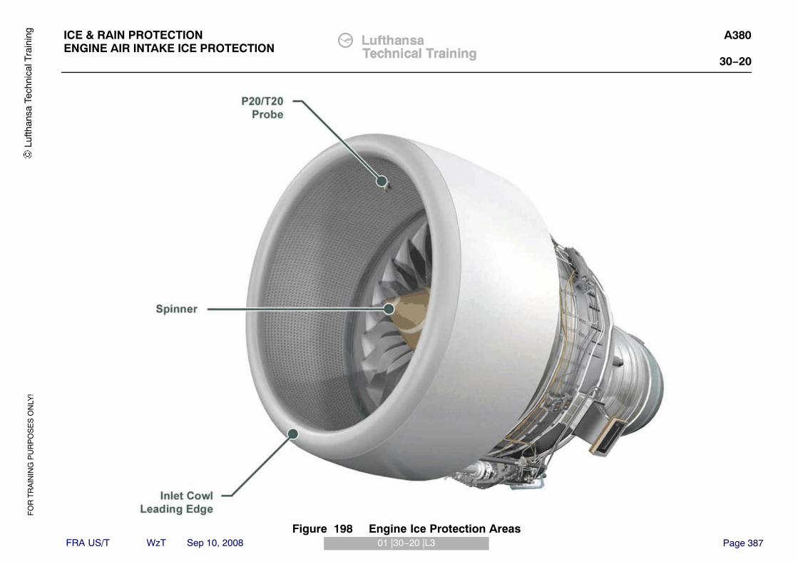
FO
R T
RA
ININ
G P
UR
PO
SE
S O
NLY
!
Page 38701 |30−20 |L3
ICE & RAIN PROTECTIONENGINE AIR INTAKE ICE PROTECTION
A380
30−20
FRA US/T WzT Sep 10, 2008
Lufth
ansa
Tec
hnic
al T
rain
ing
Figure 198 Engine Ice Protection Areas

FO
R T
RA
ININ
G P
UR
PO
SE
S O
NLY
!
Page 38802 |30−20 |L3
ICE & RAIN PROTECTIONENGINE AIR INTAKE ICE PROTECTION
A380
30−20
FRA US/T WzT Sep 10, 2008
AIR INTAKE COWL
Air Intake Cowl PresentationThe Air Intake Cowl is an interchangeable component attached to the enginefan case.The function of the Air Intake Cowl is to provide:� Smooth and sufficient air flow to the engine� Smooth air flow over the nacelle outer surfaces� Engine noise attenuation by using acoustic materials
Full acoustic attenuation treatment by using zero splice contact.The Air Intake Cowl contains the ice protection system.The Air Intake Cowl incorporates the interphone jacks and the engine P20/T20probe.Panels are provided on the Air Intake Cowl to give quick access to the internalcomponents.The Air Intake Cowl main components :� Lip (aluminium alloy)� Forward Bulkhead� Anti−Ice and P20/T20 access panels� Outer Barrel (composite)� Inner Barrel (acoustic composite)� Aft Bulkhead (titanium)� Anti−ice ducting� Fan compartment ventilation inlet scoop� Interphone jack (only on Left Hand Side)� P20/T20 probe, pipe and harness� Fan Cowl Opening Switch Boxes (both sides)
Lufth
ansa
Tec
hnic
al T
rain
ing

FO
R T
RA
ININ
G P
UR
PO
SE
S O
NLY
!
Page 38902 |30−20 |L3
ICE & RAIN PROTECTIONENGINE AIR INTAKE ICE PROTECTION
A380
30−20
FRA US/T WzT Sep 10, 2008
Outer Barrel
Inner Barrel
Lip
Anti-Ice Access Panel
Left Fan Cowl
Opening SwitchBox
Interphone Jack
Weight: 350 kg (770 lbs)
Aft Bulkhead
VentilationScoop
P20/T20 AccessPanel
P20/T20 Harness andPipe Access Panel
Right Fan Cowl
Opening SwitchBox
Nacelle Anti Ice Interface
Lufth
ansa
Tec
hnic
al T
rain
ing
Figure 199 Air Intake Cowl

FO
R T
RA
ININ
G P
UR
PO
SE
S O
NLY
!
Page 39003 |30−20 |L3
ICE & RAIN PROTECTIONENGINE AIR INTAKE ICE PROTECTION
A380
30−20
FRA US/T WzT Sep 10, 2008
Nacelle Anti−Ice SystemHot engine air is provided through the anti−ice duct and through a tube, basedon cyclone concept, inside the lip.The hot air flows inside the lip and is released overboard through the anti−iceaccess panel that is connected to the forward bulkhead.The anti−icing system can operate in all flight and ground conditions.
NAI ComponentsThe NAI components installed on the inlet cowl are as follows:� Nose cowl lip skin − defines the inlet cowl protected area� Forward bulkhead - ensures confinement of hot air in the forward part of the
nose cowl� Supply duct assembly - Ensures routing of hot air from the EBU/Nose cowl
interface to the nozzle� Cyclone Nozzle - delivers primary hot air massflow for anti−icing� Cyclone Mixer - ensures mixing of primary mass flow with recirculating air
and avoids direct impingement of primary flow on nose cowl lip� Exhaust panel - discharges hot air overboard and ensures mixing with
aerodynamic flow� Protection pipe - ensures containment of hot air that may leak from the
supply duct and directs it to the intake lip where it is discharged overboardthrough the exhaust grid.
General DescriptionThe hot air from HP compressor via the NAI valves, is ducted through the feedpipe into the air intake lip. The feed pipe is located between the aft and theforward bulkheads in the space between the inner and outer barrel. Aprotection pipe is located around the feed pipe and gives protection in theevent of duct rupture, so that it does not have an effect on the nose cowlstructure.The cyclone system is located inside the intake lip and gives a swirlingmovement to the airflow inside the intake lip.The cyclone system consists of the following:� An injector with one centre nozzle and two lateral nozzles� A mixer� Spring brackets
The mixer prevents direct impingement of the hot air onto the inlet, thuspreventing overheating. It also causes a jet pump effect, which gives good hotair recirculation around the intake lip.The hot air circulates around the intake lip a few times before being dischargedoverboard through the exhaust grid.
Lufth
ansa
Tec
hnic
al T
rain
ing

FO
R T
RA
ININ
G P
UR
PO
SE
S O
NLY
!
Page 39103 |30−20 |L3
ICE & RAIN PROTECTIONENGINE AIR INTAKE ICE PROTECTION
A380
30−20
FRA US/T WzT Sep 10, 2008
Forward Bulkhead
Cyclone Tube
Cyclone Nozzle
Lip(shown transparent) Anti Ice Duct
Anti Ice Air Exit Grid (shown transparent)
Anti Ice Access Panel (shown transparent)
Aft Bulkhead
Lufth
ansa
Tec
hnic
al T
rain
ing
Figure 200 Nacelle Anti-Ice System

FO
R T
RA
ININ
G P
UR
PO
SE
S O
NLY
!
Page 39204 |30−20 |L3
ICE & RAIN PROTECTIONENGINE AIR INTAKE ICE PROTECTION
A380
30−20
FRA US/T WzT Sep 10, 2008
NAI SYSTEM
System DescriptionThe NAI system is controlled by one of the two Anti−Ice Control Units (AICU)on the aircraft, with inputs from the Anti−Ice switches on the overhead panel.When the system is operated in AUTO mode, the AICU uses inputs fromaircraft mounted Ice detectors. In manual mode the AICU using the switchposition inputs from the overhead panel switches.There are two nacelle anti−ice valves on each engine:� One shut−off valve (SOV)� One Pressure Regulating Anti−Ice Valve (RAIV)
The shut−off valve is controlled by the AICU, via one of the solenoids in theright bleed valve controller in Zone 2. The valve is located in Zone 3 and is apneumatically operated valve using HP3 muscle pressure from the bleed valvecontroller solenoid. Downstream of the SOV is a venturi restrictor whichoperates as a flow restrictor in case of a burst duct in the fan compartment(Zone 1), This will limit flow in these conditions, but will not affect normaloperation.The pressure regulating anti−ice valve (RAIV) is located in Zone 1 and ispneumatically operated using downstream pressure. The valve regulatesdownstream pressure to avoid too high pressures on the lip skin. The valveincorporates two switches which both monitor the valve downstream pressure.The LP switch outputs to the AICU and is used to detect failures of the On/Offfunction. The HP switch outputs to the EEC, which sets a fault message if thedownstream pressure is too high.
AICU Control Unit (AICU) ControlThe two aircraft mounted AICU s perform activation and deactivation of WingAnti−Ice (WAI) and Nacelle Anti−Ice (NAI) systems based on inputs from theice detectors and cockpit pushbutton switches.Each AICU is a dual channel controller, which controls the WAI & NAI systems.They also perform monitoring of the WAI & NAI system valves. The AICU sperforms the following NAI functions:� AICU1 Channel A performs:− Engine 2 NAI control− Engine 4 NAI monitoring
� AICU1 Channel B performs:− Engine 2 NAI monitoring− Engine 4 NAI control
� AICU2 Channel A performs:− Engine 1 NAI control− Engine 3 NAI monitoring
� AICU2 Channel B performs:− Engine 1 NAI monitoring− Engine 3 NAI control
Lufth
ansa
Tec
hnic
al T
rain
ing

FO
R T
RA
ININ
G P
UR
PO
SE
S O
NLY
!
Page 39304 |30−20 |L3
ICE & RAIN PROTECTIONENGINE AIR INTAKE ICE PROTECTION
A380
30−20
FRA US/T WzT Sep 10, 2008
Lufth
ansa
Tec
hnic
al T
rain
ing
Figure 201 NAI System Schematic

FO
R T
RA
ININ
G P
UR
PO
SE
S O
NLY
!
Page 39405 |30−20 |L3
ICE & RAIN PROTECTIONENGINE AIR INTAKE ICE PROTECTION
A380
30−20
FRA US/T WzT Sep 10, 2008
NAI SHUT−OFF VALVE (SOV)
PurposeTo control the flow of HP3 air to the NAI system. The valve acts as an ON/OFFsystem
LocationThe NAI SOV is located on the lower right side of the HP combustion outercase in Zone 3.
DescriptionThe Shut−Off Valve is a solenoid operated and pneumatically actuated valve.The solenoid is contained in the right bleed valve controller in Zone 2 (coveredin 75 − Air Systems).When the solenoid is energised, HP3 servo pressure from the solenoid valveacts on the piston in the SOV, and the valve is closed against the springpressure.When the solenoid is de−energised, the HP3 servo pressure line to the valve isvented and the spring and HP3 air pressure from the compressor case, act onthe piston and valve respectively to open the valve.
NOTE: The valve is sprung−loaded in the open position.
Manual OverrideIf there are faults in the NAI system, the SOV may be locked in the openposition. The manual override is unscrewed and locked in the fully openposition. The manual override has a different colour to allow people to know ifthe valve is open or closed.
Lufth
ansa
Tec
hnic
al T
rain
ing

FO
R T
RA
ININ
G P
UR
PO
SE
S O
NLY
!
Page 39505 |30−20 |L3
ICE & RAIN PROTECTIONENGINE AIR INTAKE ICE PROTECTION
A380
30−20
FRA US/T WzT Sep 10, 2008
Lufth
ansa
Tec
hnic
al T
rain
ing
Figure 202 NAI Shut Off Valve

FO
R T
RA
ININ
G P
UR
PO
SE
S O
NLY
!
Page 39606 |30−20 |L3
ICE & RAIN PROTECTIONENGINE AIR INTAKE ICE PROTECTION
A380
30−20
FRA US/T WzT Sep 10, 2008
ANTI−ICE PRESSURE REGULATING VALVE
PurposeTo regulate the pressure of the HP3 air to the inlet cowl.
LocationThe NAI Pressure Regulating Valve is located on the lower left side of the fancase in Zone 1.
DescriptionThe Pressure Regulating Valve is a spring−loaded open, pneumaticallyactuated valve.When inlet pressure is applied to the valve, air flows past the open butterflyvalve and provides a source of pressure at the downstream sensing port. Thisdownstream pressure is used for:� Pressure regulation� Actuator positioning� Pressure switch operation
The downstream pressure is regulated to provide an outlet pressure from thevalve in the range of 65 - 83 psig.The LP switch operates in the range of 14 - 18 psig and is used to detectfailures of the On/Off function. The LP switch outputs to the AICUThe HP switch operates in the range of 85 - 98 psig and is used to detectfailures of the valve regulation system. The HP switch outputs to the EEC,which sets a fault message if the downstream pressure is too high.
Manual OverrideThe valve includes a visual indicator and a manual lock arm that can lock theNAI pressure regulating valve in either the fully open or fully closed position.The override uses a manual lock bolt that serves a dual purpose. When seatedin the storage position, the manual lock bolt holds a manual lock valve open inthe downstream sense line, which allows the valve to function normally. On theremoval of the manual lock bolt, the manual lock valve closes in thedownstream sense line, blocking off downstream pressure and venting theregulator assembly and actuator to ambient.The manual lock bolt is retained by a lanyard and threads into the manualoverride to lock it in position.
Lufth
ansa
Tec
hnic
al T
rain
ing

FO
R T
RA
ININ
G P
UR
PO
SE
S O
NLY
!
Page 39706 |30−20 |L3
ICE & RAIN PROTECTIONENGINE AIR INTAKE ICE PROTECTION
A380
30−20
FRA US/T WzT Sep 10, 2008
Lufth
ansa
Tec
hnic
al T
rain
ing
Figure 203 NAI Pressure Regulating Valve

FO
R T
RA
ININ
G P
UR
PO
SE
S O
NLY
!
Page 39807 |30−20 |L3
ICE & RAIN PROTECTIONENGINE AIR INTAKE ICE PROTECTION
A380
30−20
FRA US/T WzT Sep 10, 2008
MODE OF OPERATION AND COCKPIT INDICATIONS
Manual ModeWhen the engine anti−ice is selected on the ENG Anti−Ice P/BSW‘s the ONlegends on the switches illuminate and the MAN ENG A ICE message comeson as a MEMO item on the EWD.When manual mode is selected and icing conditions are detected by thesystem, a warning message will be displayed if the engine anti−ice is notselected ON. This will consist of a MASTER CAUT, single chime and messageadvising selection of ENG anti−ice ON.When icing conditions are no longer detected for more than 190 seconds andthe ice protection systems are selected ON, the ICE NOT DET messageilluminates as a MEMO on the EWD.
IndicationsENG P/BSW‘s − ON (blue light) or FAULT (amber light). The fault lightindicates a failure of one nacelle anti−ice system.
Lufth
ansa
Tec
hnic
al T
rain
ing

FO
R T
RA
ININ
G P
UR
PO
SE
S O
NLY
!
Page 39907 |30−20 |L3
ICE & RAIN PROTECTIONENGINE AIR INTAKE ICE PROTECTION
A380
30−20
FRA US/T WzT Sep 10, 2008
Lufth
ansa
Tec
hnic
al T
rain
ing
Figure 204 NAI Operating Mode and Indication

FO
R T
RA
ININ
G P
UR
PO
SE
S O
NLY
!
Page 40001|71|L3
POWER PLANTENGINE GROUND OPERATION
A380RR Trent 900
71
FRA US/T WzT Sep 10, 2008
DANGER AREAS OF THE ENGINE
WORKING AREAEngine Not RunningEven if the engine is not running, the area is still dangerous and the personnelhas to obey the precautions, which are given to operate an engine safely.
Engine RunningTo enable personnel safety when he has to act exceptionally on a runningengine, the power level must be kept to the minimum necessary by settingthrottle control levers to the IDLE position.The restricted areas are:� the intake suction area: in a radius of 4.5 m (15 ft),� the exhaust danger area: a corridor of 30� from the exhaust nozzles to 70 m
(230 ft) afterwards.To work on the engine safely, you must use the entry corridors located at theengine outboard side 1.3 m (4 ft) aft of the air intake cowl.
NOTE: To work on the inboard engines, the outboard engines must beshut off first.
Human factor points:
WARNING: BE CAREFUL WHEN YOU DO WORK ON THE ENGINEPARTS AFTER THE ENGINE IS SHUTDOWN. THE ENGINEPARTS CAN STAY HOT FOR ALMOST 1 HOUR.
WARNING: UNDER NORMAL CONDITIONS, EXCEPT IN THE ASSISTEDMANUAL START SEQUENCE, THERE IS NO NEED AND IT ISNOT ALLOWED TO PERFORM MAINTENANCE TASKS ON ARUNNING ENGINE.
WARNING: DO NOT GO NEAR AN ENGINE THAT IS IN OPERATIONABOVE LOW IDLE. IF YOU DO, IT CAN CAUSE AN INJURY.GO NEAR AN ENGINE IN OPERATION THROUGH THEENTRY CORRIDORS ONLY.
WARNING: KEEP ALL PERSONS OUT OF THE DANGER AREAS DURINGENGINE OPERATION.CLEAN THE RAMP IF THERE IS SNOW, ICE, WATER, OIL OROTHER CONTAMINATION OR MOVE THE AIRCRAFT TO ALOCATION THAT IS CLEAN.MAKE SURE THAT ALL PERSONS ARE SAFE BEFORE YOUSTART THE ENGINE.MAKE SURE THE PERSONS IN THE COCKPIT CAN SPEAKTO ALL PERSONS NEAR THE DANGER AREA DURINGENGINE OPERATION.OBEY ALL OF THE GROUND SAFETY PRECAUTIONS FORTHE ENGINES.THE ENGINES CAN PULL PERSONS OR UNWANTEDMATERIALS INTO THEM AND CAUSE SERIOUS INJURIESOR DAMAGE TO EQUIPMENT
Lufth
ansa
Tec
hnic
al T
rain
ing

FO
R T
RA
ININ
G P
UR
PO
SE
S O
NLY
!
Page 40101|71|L3
POWER PLANTENGINE GROUND OPERATION
A380RR Trent 900
71
FRA US/T WzT Sep 10, 2008
INTAKE SUCTION DANGER AREA MAX TAKE−OFF POWER
EXHAUST DANGER AREA
8.9 m(29 ft)
30TO 548.6 m (1800 ft) AFT OF EXHAUST NOZZLES
INTAKE SUCTION DANGER AREA MINIMUM IDLEWPOWER
EXHAUST DANGER AREA
ENTRY CORRIDOR
70 m(230 ft)
30 �
4,5 m(15 ft)
1,3 m(4 ft 3 in)
Lufth
ansa
Tec
hnic
al T
rain
ing
Figure 205 Engine Danger Areas

FO
R T
RA
ININ
G P
UR
PO
SE
S O
NLY
!
Page 40202|71/L3
POWER PLANTENGINE GROUND OPERATION
A380RR Trent 900
71
FRA US/T WzT Sep 10, 2008
POWER PLANT GROUND OPERATIONPREPARE THE AIRCRAFT / ENGINE FOR GROUND OPERATIONTask 71−00−00−860−803−AObey the instructions that follow:
WARNING: YOU MUST OBEY THE PRECAUTIONS THAT ARE GIVENFOR PERSONS TO OPERATE AN ENGINE SAFELY. IF YOUDO NOT, AN INJURY AND/OR DAMAGE CAN OCCUR.
The ground operation time for the engine.Do not start the engine, unless it is necessary.You must keep the ground operation time of the engine to a minimum.When you operate the engine, change the engine speed slowly.
NOTE: Movements of the throttle lever (to increase or decrease theengine speed) must be smooth and slow. Unless the instructionis different, the controlled movement must take at least 30seconds.When you operate the engine on the ground, keep thepower level and the time of the operation to the minimum that isnecessary.
NOTE: When you must do more than one task that makes it necessaryto operate the engine, try to do the tasks at the same time.
The safety precautions for the ground operation of an engine.Make sure that the aircraft is pointed into the wind.Make sure that the ground surface in the engine ground operations area is notbroken or loose and is clear of unwanted materials.
NOTE: The ground operation area is 12.19 m (40 ft.) each side of theengine center line and 18.28 m (60 ft.)forward from the rear ofthe engine.
Make sure that the aircraft is clear of all structures and other aircraft. Makesure the engine exhaust danger area for all engines is clear.
NOTE: If a blast fence is necessary, it is recommended that the enginenozzle is positioned at least 60.96 m (200 ft.) from it. If theengine is operated less than 60.96 m (200 ft.) from the blastfence, it is possible that the engine will not be stable.
Make sure that the aircraft brakes are on. Make sure that the CHOCK −WHEEL are in position in front of each forward wheel of the WLG (WingLanding Gear).
NOTE: If engine start is followed by a high power run, useCHOCK−WHEEL, ENGINE RUN UP (98L10001005000).
Make sure that there are no COVER − PROTECTION on the engine.Make sure that there are no unwanted objects in the engine inlet and exhaust.Make sure that the engine inlet and exhaust danger areas are clear of personsand ground support equipment.Make sure that unwanted persons and unwanted vehicles cannot easily enterthe danger areas.Make sure that persons with loose clothing do not go near the engine.Make sure that the ground fire extinguisher equipment is in its position with theapplicable persons.Make sure that the fan cowl panels are closed before you operate the engine.
NOTE: The fan cowl panels can be open for specified tests, for exampleleak tests. The applicable procedure will tell you when to keepthe fan cowl panels open.
The entry corridors.
WARNING: YOU MUST NOT GO NEAR AN ENGINE THAT IS INOPERATION ABOVE LOW IDLE. IF YOU DO, IT CAN CAUSEAN INJURY. WHEN AN ENGINE IS IN OPERATION AT LOWIDLE, YOU CAN ONLY GO NEAR IT THROUGH THE ENTRYCORRIDORS.
Make sure that you use the entry corridors to go near an engine that is inoperation at low IDLE (forward thrust only).Make sure that you do not operate the engine above low IDLE with persons inthe entry corridor.
NOTE: If the engine is in operation at more than low IDLE, refer to thetake−off power danger areas or to the breakaway power dangerareas.
Lufth
ansa
Tec
hnic
al T
rain
ing

FO
R T
RA
ININ
G P
UR
PO
SE
S O
NLY
!
Page 40302|71/L3
POWER PLANTENGINE GROUND OPERATION
A380RR Trent 900
71
FRA US/T WzT Sep 10, 2008
Ear protection.WARNING: WARNING: YOU MUST USE EAR PROTECTION WHEN YOU
ARE NEAR AN ENGINE THAT IS IN OPERATION. THE NOISEMADE BY AN ENGINE IN OPERATION CAN CAUSEPERMANENT DAMAGE TO YOUR EARS.
Make sure that you use the correct ear protection when you are near an enginethat is in operation.
The engine operation.Do not operate the engine on the ground, at more than the engine limitsEngine power control.Keep the power level and the time of the operation at the minimum that isnecessary.Make sure that you move the throttle levers slowly unless, because of theprocedure, it is necessary to move them differently.
NOTE: Fast movement of the throttle levers can cause the enginetemperature to change quickly. This will decrease the life of theengine.
Crosswind conditions and engine surges.Make sure that you obey the wind direction and velocity limits for engineoperation.Bad wind conditions (turbulence, gusty, crosswind) while you operate theengine at middle power and above can cause:� The engine parameters (TPR (Turbine Power Ratio), EGT (Exhaust Gas
Temperature), RPM (Revolution Per Minute)) to increase or decrease andnot stay constant
� A roar from the air intake to be heard.If you hear the intake roar you must immediately decrease the engine power. Itis not permitted that you run the engine in these conditions. You can identify anengine surge by an increase in EGT and a sudden increase in noise from theengine.
If an engine surge occurs you must:� Immediately decrease the engine power until the engine surge stops.� Make sure that the EGT decreases.� Let the engine become stable at low idle.� Slowly increase the engine power.� Look at the engine parameters to see if the engine has a surge again.� If the surge does not occur again, continue with the engine test procedure.� If the engine has a surge again, because of bad wind conditions, stop the
engine procedure. It is not necessary to examine the engine for this type ofsurge.
� If the engine has a surge again, not caused by bad wind conditions,immediately decrease power to low idle. Let the engine cool for 5 minutes,then stop the engine. Find the cause of the surge.
Static electricity discharge from the LP compressor spinner.If you operate the engine on the ground in a low−humidity condition, you cansee sparks around the LP compressor spinner. This will not cause damage tothe engine.
Lufth
ansa
Tec
hnic
al T
rain
ing

FO
R T
RA
ININ
G P
UR
PO
SE
S O
NLY
!
Page 40402|71/L3
POWER PLANTENGINE GROUND OPERATION
A380RR Trent 900
71
FRA US/T WzT Sep 10, 2008
The engine anti−ice.You must use the engine anti−ice if the conditions that follow occur:If the OAT (Outside Air Temperature) is less than 6 deg.C (43 deg.F) andmoisture (fog, rain, snow, sleet or hail) is seen.
NOTE: Fog is specified as visibility lower than 300 m (984 ft.) due tomoisture.
If it is necessary to use the engine anti−ice, set the applicable ENG ANTI ICEswitch to ON immediately after the engine gets to low idle.Do not do the performance test procedures when the ENG ANTI ICE switch isset to ON.
NOTE: The performance limits are given with the air off−takes set toOFF.
Do the steps that follow if you must do the performance test when conditionsmake the use of the anti−ice system necessary.Make sure that there is no ice on the air intake cowl before you set the ENGANTI ICE switch to OFF.When you must make a record of the engine indications, set the ENG ANTIICE switch to OFF for a maximum of 60 seconds.Immediately after you make a record of the engine indications, set the ENGANTI ICE switch to ON.Make sure that there is no ice on the air intake cowl before you set the ENGANTI ICE switch to OFF again.
CAUTION: IF YOU OPERATE THE ENGINE IN FREEZING FOG, YOUMUST DE−ICE THE ENGINE CORE INLET REGULARLY. THEMAXIMUM PERMITTED TOTAL TIME OF OPERATION INTHESE CONDITIONS IS 60 MINUTES (UNLESS THE ENGINECORE INLET IS DE−ICED DURING THAT PERIOD). IF YOUOPERATE THE ENGINE FOR LONGER, TOO MUCH ICE CANBUILD−UP ON THE CORE INLET COMPONENTS. THESUBSEQUENT RELEASE OF THIS ICE, AT HIGHER POWER,CAN CAUSE DAMAGE TO THE COMPRESSOR.
Lufth
ansa
Tec
hnic
al T
rain
ing

FO
R T
RA
ININ
G P
UR
PO
SE
S O
NLY
!
Page 40502|71/L3
POWER PLANTENGINE GROUND OPERATION
A380RR Trent 900
71
FRA US/T WzT Sep 10, 2008
The engine start. The engine start is satisfactory if these conditions occur:On the panel 1125VU, the engine starts in 30 seconds or less after the ENGMASTER control switch is set to ON.The engine speed increases smoothly and continuously to low idle.The EGTstays in the limits.The engine start is unsatisfactory if these conditions occur:Hot start or impending hot start� A start when the EGT goes near or higher than the start limit.
Hung start� The engine light−up is satisfactory but it does not accelerate correctly
(speed increases slowly or decreases) and the EGT goes near to its limit.Aborted start� The start procedure is stopped before the start is completed.
A cold weather condition start.
CAUTION: YOU MUST NOT START, DRY MOTOR OR WET MOTOR THEENGINE IF THE OIL TEMPERATURE IS LESS THAN MINUS10 DEG.C (14 DEG.F). LOW OIL TEMPERATURES CANCAUSE DAMAGE TO THE ENGINE BEARINGS.
CAUTION: IF THE ENGINE IS IN A COLD ENVIRONMENT, THE ENGINEOIL CAN BECOME TOO COLD. IF THE ENGINE IS NOTOPERATED, AND IS IN THIS ENVIRONMENT, YOU MUST DOA CHECK OF THE ENGINE OIL TEMPERATURE REGULARLY.IF NECESSARY, REGULARLY START THE ENGINE ANDOPERATE IT AT IDLE TO KEEP THE OIL TEMPERATUREABOVE MINUS 10 DEG.C (14 DEG.F).
Make sure that the oil temperature is more than −10 deg.C (14 deg.F) beforeyou start the engine. To find the engine oil temperature:� Do the steps necessary to set the ECAM (Electronic Centralized Aircraft
Monitoring) screen to the engine page� Look at the ECAM display screen and get the oil temperature value from the
applicable SD (System Display).
At ambient temperatures below −40 deg.C (−40 deg.F), do a check of thevibration indication on the ECAM screen. If the vibration indication is not seenon the ECAM screen, do the steps that follow:Warm the EMU (Engine Monitoring Unit). To warm the EMU, on the panel1215VM, select the applicable ENG START selector switch to IGN START.
NOTE: When the EMU is warm, a vibration indication will be seen on theECAM screen. It can be 15 minutes before the EMU is warm.When the vibration indication is seen on the ECAM screen, onthe ENG START section of the panel 1215VM, select theapplicable ENG START selector switch to NORM.
Do the applicable autostart or manual start, immediately.When you start a cold soaked engine these conditions can occur:� The engine oil pressure can be more than 100 psi (6.89 bar).� The indication for oil quantity can decrease.
When the engine becomes stable at the low idle condition:� The oil temperature will rise.� The oil pressure will decrease.� The indication for the oil quantity will become normal.
Do not operate the engine above idle until the oil quantity indication issatisfactory.
NOTE: If the start procedure takes a long time to complete, theindication for the oil pressure can decrease. You can also have awarning for low oil pressure. These conditions are permitted if theoil system parameters go to their normal values when the enginebecomes stable at low idle.
NOTE: If you stop the start because of an indication of low oil quantityand LP warning, you can start the engine again. But do not addoil to the oil tank.
NOTE: If the start is satisfactory, make sure that the oil parametersreturn to the normal limits when the engine is at low idle.
Lufth
ansa
Tec
hnic
al T
rain
ing

FO
R T
RA
ININ
G P
UR
PO
SE
S O
NLY
!
Page 40602|71/L3
POWER PLANTENGINE GROUND OPERATION
A380RR Trent 900
71
FRA US/T WzT Sep 10, 2008
ENGINE OPERATION LIMITS
Exhaust Gas Temperature (EGT) limits.Ground start:� 700 deg.C (1292 deg.F) at less than 50 percent N3.� In−flight relight: 850 deg.C (1562 deg.F).
Maximum continuous: 850 deg.C (1562 deg.F).Takeoff: 900 deg.C (1652 deg.F) for a maximum of 5 minutes, or 10 minutes inthe event of an engine failure.
Oil pressure limits.The minimum oil pressure with N3 at or above idle is 25 psi (1.7 bar) differentialpressure.
NOTE: An engine oil pressure indication is shown in the cockpit. This isan adjusted indication if the engine RPM is above 70% N3. Thisis so that the in−flight LP advisory message and the low oilpressure warning are given at the same time. The low oilpressure warning is given if engine oil pressure is 25 psi (1.724bar) or less.
Oil temperature limits.
CAUTION: YOU MUST NOT START, DRY MOTOR OR WET MOTOR THEENGINE IF THE OIL TEMPERATURE IS LESS THAN MINUS10 DEG.C (14 DEG.F). LOW OIL TEMPERATURES CANCAUSE DAMAGE TO THE ENGINE BEARINGS.
At start, the oil temperature must be more than a minimum of −10 deg.C (14deg.F).Before acceleration to take−off, the oil temperature must be 60 deg.C (140deg.F) or more.The maximum oil temperature is 196 deg.C (384.8 deg.F) when the operationcondition is stable.
Oil consumption limits.The maximum oil consumption is 0.45 l/hr (0.48 USQT/hr).The usual engine oil consumption is 0.095 l/hr (0.1 USQT/hr).If the engine has an increase in oil consumption above 0.14 l/hr (0.15USQT/hr), do the high oil consumption troubleshooting
Rotor operation speed limits.The maximum N1 is 96.1 percent rpm (100 percent = 2900 rpm).The maximum N2 is 97.8 percent rpm (100 percent = 8300 rpm).The maximum N3 is 97.8 percent rpm (100 percent = 12200 rpm).
NOTE: You must tell Rolls−Royce plc if an overspeed condition occurs.Give Rolls−Royce the exceedance data from the OMT and theengine standard from the data plate.
NOTE: Engine speed can be reduced by the EEC (Engine ElectronicController) to less than the specified limits above.
Static engine operation.Stable operation in the speed range 64 to 72 percent N1 or above 78 percentN1 is not permitted during static ground operations. But temporary operationthrough the speed range 64 to 72 percent N1 is permitted while the thrustincreases or decreases. The EEC automatically prevents operation in thesespeed ranges in primary and rated reversionary thrust control modes.
Starter motoring limits.Continuous motoring:� The maximum time is five minutes.� After continuous motoring of five minutes the starter must be cooled for 30
minutes, before the starter is motored again.� Intermittent motoring.
The total motoring time permitted is five minutes in any 35 minutes time period.
Vibration Advisory Limits.Cockpit alert level:1 LP band 5 units (1.00 in./second peak velocity).2 IP band 5 units (0.9 in./second peak velocity).3 HP band 5 units (0.7 in./second peak velocity).
Lufth
ansa
Tec
hnic
al T
rain
ing

FO
R T
RA
ININ
G P
UR
PO
SE
S O
NLY
!
Page 40702|71/L3
POWER PLANTENGINE GROUND OPERATION
A380RR Trent 900
71
FRA US/T WzT Sep 10, 2008
��� ���
���
RELATIVE WIND
RECOMMENDED 30 KNOTSMAXIMUM WIND VELOCITY
PERMITTED 10 KNOTSMAXIMUM WIND VELOCITY
PERMITTED 5 KNOTS MAXIMUM WINDVELOCITY (limited up to high idle)
NO LIMIT
PERMITTED 35 KNOTSMAXIMUM WIND VELOCITY
PERMITTED 20 KNOTSMAXIMUM WIND VELOCITY
GROUND OPERATIONS UP TO THE MAXIMUM N1GROUND LIMIT (ref TASK 71−00−00−860−810)
GROUND OPERATIONSUP TO LOW IDLE
The wind velocity is for stablewind conditions. Decrease themaximum wind limit 5 knots forgusty wind conditions.
Lufth
ansa
Tec
hnic
al T
rain
ing
Figure 206 Ground Operations-Crosseind Condtions

FO
R T
RA
ININ
G P
UR
PO
SE
S O
NLY
!
Page 40803|71|L3
POWER PLANTENGINE GROUND OPERATION
A380RR Trent 900
71
FRA US/T WzT Sep 10, 2008
ENGINE START ASSISTANCE OPS/CTL & IND
GeneralThis is a general view of the A380 cockpit.
Lufth
ansa
Tec
hnic
al T
rain
ing

FO
R T
RA
ININ
G P
UR
PO
SE
S O
NLY
!
Page 40903|71|L3
POWER PLANTENGINE GROUND OPERATION
A380RR Trent 900
71
FRA US/T WzT Sep 10, 2008
Lufth
ansa
Tec
hnic
al T
rain
ing
Figure 207 Engine Start Assistance Ops/Ctl & Ind.

FO
R T
RA
ININ
G P
UR
PO
SE
S O
NLY
!
Page 41004|71|L3
POWER PLANTENGINE GROUND OPERATION
A380RR Trent 900
71
FRA US/T WzT Sep 10, 2008
Engine Start Controls & Panels LocationOn the overhead panel, the engine controls are:� ENGine FADEC GrouND PoWeR panel,� ENG START mode selector,� ENG MANual START panel,
On the center pedestal, the engine start controls are:� ENG MASTER levers,� ENG Throttle Control Levers.
Lufth
ansa
Tec
hnic
al T
rain
ing

FO
R T
RA
ININ
G P
UR
PO
SE
S O
NLY
!
Page 41104|71|L3
POWER PLANTENGINE GROUND OPERATION
A380RR Trent 900
71
FRA US/T WzT Sep 10, 2008
Lufth
ansa
Tec
hnic
al T
rain
ing
Figure 208 Engine Start Controls & Panels Location

FO
R T
RA
ININ
G P
UR
PO
SE
S O
NLY
!
Page 41205|71|L3
POWER PLANTENGINE GROUND OPERATION
A380RR Trent 900
71
FRA US/T WzT Sep 10, 2008
ENGINE START ASSISTANCE DESCRIPTION
Ignition System ArchitectureEach engine has two independent ignition systems, which give an electricalspark used to start ignition of the fuel/air mixture in the engine.The engine starting, ignition controls are found on the following cockpit panels:� ENGine START control panel, on the overhead control panel,� ENG MASTER control panel, on the center pedestal,� ENG MANual START panel, on the overhead control panel.
All these controls are linked to the Input/Output Modules (IOMs) type A. TheIOMs are themselves linked to the EEC (Engine Electronic Controller) via theADCN (Avionics Data Communication Network). This enables the EEC tocontrol the engine starting sequences, engine cranking options and the ignitionselection in response to aircraft command signals.The ENG MASTER levers are hardwired to the EEC for reset and back−uppurposes if the ADCN fails. The EEC also interfaces with the ignition units andthe Starter Control Valves, in order to control and monitor their operation duringthe starting or cranking phases.The EIPM (Engine Interface Power Management) maintains the power supplyto the EEC and supplies the ignition system with 115 VAC.The ignition leads transmit the electrical power from the ignition units to theigniter plugs. Throttle control lever sends an analogic signal to the EEC toenable it to compute the correct thrust to be applied.
Automatic StartThe EEC does the selection of an automatic engine start after reception of theappropriate cockpit commands. The EEC will automatically shut down theengine if the start procedure is not satisfactory.For automatic start of the engine, the controls have to be selected as follows:� the MAN START P/BSW on the ENG panel is off (ON legend is off),� the thrust lever is set to the IDLE position,� the rotary selector on the ENG START panel is set to the IGNition/START
position,� the lever on the ENG MASTER panel is set to the ON position.� once the engine is running the ENG START rotary selector is set to NORM
position.
Manual StartAlternatively the engine can be started manually with the flight crew ormaintenance personnel in control of the start sequence. In this mode theengine starting control is under limited authority of the EEC. After reception ofthe appropriate cockpit commands the EEC system has a limited interaction tocontrol the starter control valve, fuel and igniters.For manual ground start of the engine, the controls have to be selected asfollows:� the thrust lever is set to the IDLE position,� the rotary selector on the ENG START panel is set to the IGN/START
position,� the MAN START P/BSW on the ENG panel is set to ON,� the applicable N2 (intermediate pressure shaft) and N3 (HP shaft) rotation
speeds are monitored on the ENGINE page of the ECAM SD and theprocedure continues when they are reached,
� the lever on the ENG MASTER panel is set to the ON position at 25% N3and EGT (Exhaust Gas Temperature) less than 150�C (302�F),
� the normal EGT rise is checked on the E/WD by means of an indicationlight−up,
� the applicable N1 (LP compressor rotation speed) is monitored on the EWDand the procedure continues when it is reached,
� once the engine is running MAN START P/BSW goes off,� the ENG START rotary selector is set to NORM position.
WARNING: USE SPECIFIC EQUIPMENTS (FIRE FIGHTING,COMMUNICATION...).
Lufth
ansa
Tec
hnic
al T
rain
ing

FO
R T
RA
ININ
G P
UR
PO
SE
S O
NLY
!
Page 41305|71|L3
POWER PLANTENGINE GROUND OPERATION
A380RR Trent 900
71
FRA US/T WzT Sep 10, 2008
Lufth
ansa
Tec
hnic
al T
rain
ing
Figure 209 Engine Start Assistance

FO
R T
RA
ININ
G P
UR
PO
SE
S O
NLY
!
Page 41406|71|L3
POWER PLANTENGINE GROUND OPERATION
A380RR Trent 900
71
FRA US/T WzT Sep 10, 2008
Engine StartAfter the preliminary cockpit preparation has been done, the engine start canbe initiated.
Normal Start ProcedureIn normal start procedure, you start engine in automatic mode.To start the engine in normal procedure:� Turn the ENG START selector on ”IGNition START” position, the ECAM
ENG page appears,� Check if all indications are normal and all parameters for logical indications,� Ask the ground clearance to start the engine,� If you obtain this clearance, announce the start engine,� Check the air pressure is above 30 psi on the ECAM,� Set the ENG MASTER lever to ON,� On the ECAM, check that the start valve is in line and the start valve air
pressure is upper 30 psi. The N3 and the oil pressure increase, When N3 isequal to 25%, the active igniter (A or B) is indicated and the fuel flows.
� Start the chronometer and within 30 seconds, the EGT increases,� At N3 above 30%, N1 increases and the oil pressure is green,� At N3 above 50%, the start valve is cross line and the igniter indication
disappears,� When the engine is at idle, check parameters for logical indication.
Engine Start Valve FaultIf a start valve fault is detected during engine start in automatic mode:� a single chime sounds,� the MASTER CAUTion lights come on,� the ENG 2 START VALVE FAULT message is displayed on E/WD,� the ENG START VALVE FAILED CLOSED caution is displayed on ECAM
ENG page.With the failure of the engine start in automatic mode, you can perform theengine start in manual mode with ground mechanic assistance.
Lufth
ansa
Tec
hnic
al T
rain
ing

FO
R T
RA
ININ
G P
UR
PO
SE
S O
NLY
!
Page 41506|71|L3
POWER PLANTENGINE GROUND OPERATION
A380RR Trent 900
71
FRA US/T WzT Sep 10, 2008
Lufth
ansa
Tec
hnic
al T
rain
ing
Figure 210 Engine Start

FO
R T
RA
ININ
G P
UR
PO
SE
S O
NLY
!
Page 41607|71|L3
POWER PLANTENGINE GROUND OPERATION
A380RR Trent 900
71
FRA US/T WzT Sep 10, 2008
Engine Start with AssistanceIn case of the engine start failure in automatic mode, you will have to perform aspecific procedure to start the engine in manual mode with ground mechanicassistance:
Start ProcedureBefore you start the engine, check the cockpit configuration:� the ENG 1 MASTER LEVER is OFF,� the ENG 2 MASTER LEVER is OFF,� the ENG 3 MASTER LEVER is OFF,� the ENG 4 MASTER LEVER is OFF,� the ENG START selector switch is on NORMAL position,� the ENG 1 MAN START is NORMAL,� the ENG 2 MAN START is NORMAL,� the ENG 3 MAN START is NORMAL,� the ENG 4 MAN START is NORMAL,� the ALTerNate MODE is NORMAL,� the ENG 1 FIRE is NORMAL,� the ENG 2 FIRE is NORMAL,� the ENG 3 FIRE is NORMAL,� the ENG 4 FIRE is NORMAL,� the ENG 1 THROTTLE CONTROL LEVER is on FWD IDLE position,� the ENG 2 THROTTLE CONTROL LEVER is on FWD IDLE position,� the ENG 3 THROTTLE CONTROL LEVER is on FWD IDLE position,� the ENG 4 THROTTLE CONTROL LEVER is on FWD IDLE position,� the ENG 2 THRUST REVERSER LEVER is on STOW POSITION,� the ENG 3 THRUST REVERSER LEVER is on STOW POSITION,� ECAM−E/WD & SD are powered,� the FUEL PUMPS are ON,� the FLAPS LEVER POSITION is at 0 position,� the PARKING BRAKE is ON,
Inform the GROUND CREW before you start the engine.
Radio Management PanelUse flight or service interphone to establish the contact with the groundpersonnel. The RMPs (Radio Management Panels) located in the centerpedestal panel give the controls to manage this communication.With the CALLS/MECH P/BSW on the overhead panel you can make a call tothe ground mechanic and you can validate a call from the ground mechanic bypressing the MECH P/BSW on the RMP (cf ATA23).
Lufth
ansa
Tec
hnic
al T
rain
ing

FO
R T
RA
ININ
G P
UR
PO
SE
S O
NLY
!
Page 41707|71|L3
POWER PLANTENGINE GROUND OPERATION
A380RR Trent 900
71
FRA US/T WzT Sep 10, 2008
Lufth
ansa
Tec
hnic
al T
rain
ing
Figure 211 Engine Start Procedure

FO
R T
RA
ININ
G P
UR
PO
SE
S O
NLY
!
Page 41808|71|L3
POWER PLANTENGINE GROUND OPERATION
A380RR Trent 900
71
FRA US/T WzT Sep 10, 2008
Starter Control Valve OverrideThe starter control valve is installed in the starter duct at the lower left side ofthe fan case. Normally controlled by the EEC, the starter control valve controlsthe flow of air to the pneumatic starter.When the starter control valve fails to open, the START VLV FAULT messageis shown on the EWD. The starter control valve can be manually open fordispatch reasons without opening the fan cowl door. Access is availablethrough a spring−loaded flap in the fan cowl door. The manual override of thestarter control valve shall be possible by applying a DRIVE 3/8−inch −SQUARE to the square socket installed on the valve.During this operation the maintenance personnel has to stay in contact with thecockpit through the service interphone whose connection is located at the airintake cowl. Only the cockpit crew orders to open the valve, the tool has to berotated counter clockwise until the end stop is reached. The valve is kept in thisposition until the cockpit crew order to close it. This order is given after 50% ofN3 is reached. Rotating the tool clockwise until the end stop is reached closesthe starter control valve.
WARNING: BE CAREFUL WHEN WORKING ON A HOT RUNNINGENGINE,
WARNING: USE SPECIFIC EQUIPMENTS (ACCESS PLATFORM,GLOVES, HEADSET...).
Lufth
ansa
Tec
hnic
al T
rain
ing

FO
R T
RA
ININ
G P
UR
PO
SE
S O
NLY
!
Page 41908|71|L3
POWER PLANTENGINE GROUND OPERATION
A380RR Trent 900
71
FRA US/T WzT Sep 10, 2008
DRIVE 3/8 INSQUARE
WRENCH
SQUARE SOCKET(MANUAL OVERRIDE)
CHANNEL A & BELECTRICAL
CONNECTORS
ACTUATORASSEMBLY
STARTER CONTROL VALVE
FAN COWL DOOR
LEFTFAN
COWLUP/DOWNSWITCH
MAINTENANCEINTERPHONE
JACK
MANUAL OVERRIDE
ECAM/EWD MEMO ZONE
SPRING LOADED FLAP
Lufth
ansa
Tec
hnic
al T
rain
ing
Figure 212 Starter Control Valve Override

FO
R T
RA
ININ
G P
UR
PO
SE
S O
NLY
!
Page 42009|71|L3
POWER PLANTENGINE GROUND OPERATION
A380RR Trent 900
71
FRA US/T WzT Sep 10, 2008
Engine Manual StartThe procedure to start the engine in manual mode is to:� Set the ENG START selector to the ”IGN/START” position. The ECAM
ENGINE page is displayed.� Check if all indications are normal and all parameters for logical indications,� Ask the ground clearance to start the engine,� If the GROUND CLEARANCE is OBTAIN, announce the engine 2 start,� Check the air pressure is above 30 psi on the ECAM ENGINE page,� Set the ENG MAN START 2 to the ”ON” position.� Contact the ground crew to turn the start valve in OPEN position.� On the ECAM, check that the start valve is in line and the start valve air
pressure is upper 30 psi. The N3 and the oil pressure increase,� When N3 reaches 20%, set the ENG MASTER lever to the ”ON” position.
On ECAM ENGINE page the active igniter (A or B) and the fuel flow areindicated.
� Start the chronometer and within 30 seconds, the EGT increases,� At N3 above 30%, N1 increases and the oil pressure is green.� At N3 above 50%, contact the ground mechanic crew to close the start
valve, the start valve is in cross line and the igniter indication disappears.� Set the ENG MAN START to the ”OFF” position� When the engine is at idle, check parameters for logical indication.
Lufth
ansa
Tec
hnic
al T
rain
ing

FO
R T
RA
ININ
G P
UR
PO
SE
S O
NLY
!
Page 42109|71|L3
POWER PLANTENGINE GROUND OPERATION
A380RR Trent 900
71
FRA US/T WzT Sep 10, 2008
Lufth
ansa
Tec
hnic
al T
rain
ing
Figure 213 Engine Manual Start - Starter Valve Open

FO
R T
RA
ININ
G P
UR
PO
SE
S O
NLY
!
Page 42209|71|L3
POWER PLANTENGINE GROUND OPERATION
A380RR Trent 900
71
FRA US/T WzT Sep 10, 2008
THIS PAGE INTENTIONALLY LEFT BLANK
Lufth
ansa
Tec
hnic
al T
rain
ing

FO
R T
RA
ININ
G P
UR
PO
SE
S O
NLY
!
Page 42309|71|L3
POWER PLANTENGINE GROUND OPERATION
A380RR Trent 900
71
FRA US/T WzT Sep 10, 2008
Lufth
ansa
Tec
hnic
al T
rain
ing
Figure 214 Engine Manual Start - Starter Valve Closed

FO
R T
RA
ININ
G P
UR
PO
SE
S O
NLY
!
Page 42410|71|L3 REV
POWER PLANTENGINE GROUND OPERATION
A380RR Trent 900
71
FRA US/T WzT Feb 23, 2009
IGNITION AND STARTING SYSTEM DESCRIPTIONThe ignition and starting system has three subsystems:� Starting,� Fuel command,� Ignition.
StartingEngines can be started using the APU air bleed, a ground air supply orcrossbleed air from an operating engine.The EEC (Engine Electronic Controller) controls the opening and closing of theSCV (Starter Control Valve) in all start modes. The SCV controls the air flow tothe pneumatic starter. The Pneumatic starter drives N3 through the accessorygearbox.The starter has three different cycles:� Normal cycle runs:− Up to 2 minutes continuous operation then runs down to zero N3,− Up to 2 minutes continuous operation then runs down to zero N3,− Up to 1 minute continuous operation then runs down to zero N3 and wait
30 minutes for the cooling.� Extended start cycle:− Up to 5 minutes continuous operation followed by 30 minutes wait for the
cooling.� Extended crank cycle:− Up to 5 minutes continuous operation followed by 30 minutes wait for the
cooling.
Fuel commandThe EEC controls, through the MV (Metering Valve) servovalve, the FMV (FuelMetering Valve) which regulates the fuel flow to the manifolds.The ENGine MASTER lever controls, through the airframe shutdown solenoid,the closing of the HP SOV (High Pressure Shut−OFF Valve).The HPSOV is also called the MP SOV (Minimum Pressure Shut−Off Valve).EEC controls through the protection motor the closing of the HPSOV.The Fuel Flow Transmitter (FF XMTR) sends his data to the EEC.
Ignition units power supplyThe EIPM (Engine Interface Power Management) supplies ignition units (A andB) through the EEC (channel A and B) control.A/C EMERgency BUS BAR 115 VAC supplies EIPM CHAN A function. EIPMCHAN A function could supply Ignition unit A or B depending on the EECswitching.A/C BUS 2 BAR 115 VAC supplies EIPM CHAN B function. EIPM CHAN Bfunction could supply Ignition unit A or B depending on the EEC switching.EEC ignition units switching function:Each EEC channel is able to control the switching of the power supply of thetwo ignition units A and B.During an engine auto start on ground, the EEC controls automatically theswitching of the ignition units A or B.During an engine manual start, the EEC controls both ignition units A and B, forignition efficiency.
NOTE: During Engine auto start in flight, both ignition units areenergized, for redundancy.
Lufth
ansa
Tec
hnic
al T
rain
ing

FO
R T
RA
ININ
G P
UR
PO
SE
S O
NLY
!
Page 42510|71|L3 REV
POWER PLANTENGINE GROUND OPERATION
A380RR Trent 900
71
FRA US/T WzT Feb 23, 2009
Lufth
ansa
Tec
hnic
al T
rain
ing
Figure 215 Engine Starting System Description 1

FO
R T
RA
ININ
G P
UR
PO
SE
S O
NLY
!
Page 42610|71|L3 REV
POWER PLANTENGINE GROUND OPERATION
A380RR Trent 900
71
FRA US/T WzT Feb 23, 2009
Controls from the cockpitThe engine start/crank is controlled from the cockpit by:� ENGine rotary selector,� ENGine MASTER levers,� ENGine MANual START P/B SW,� TCA (Throttle Control Assembly).
System functionsThe engine can be started in two manners:� Automatic start (normal procedure),� Manual start (back−up procedure).
The engine can be cranked in two manners:� Dry crank,� Wet crank.
Continuous relight function:� Manually selected with ENG START rotary selector to the ”IGN/START”
position.Auto−relight function:� When a flame−out is detected the system energizes the two igniters. Quick
relight function (in flight only):� When the ENG MASTER lever is inadvertently selected ”OFF”, the ENG
MASTER lever can be selected ”ON” again within 30 seconds to cancel theshutdown sequence.
Lufth
ansa
Tec
hnic
al T
rain
ing

FO
R T
RA
ININ
G P
UR
PO
SE
S O
NLY
!
Page 42710|71|L3 REV
POWER PLANTENGINE GROUND OPERATION
A380RR Trent 900
71
FRA US/T WzT Feb 23, 2009
Lufth
ansa
Tec
hnic
al T
rain
ing
Figure 216 Engine Starting System Description 2

FO
R T
RA
ININ
G P
UR
PO
SE
S O
NLY
!
Page 42811|71|L3
POWER PLANTENGINE GROUND OPERATION
A380RR Trent 900
71
FRA US/T WzT Sep 10, 2008
ENGINE START / CRANK CONTROL DESCRIPTION
Instructions and Precautions for Engine Ground Operation
WARNING: YOU MUST NOT GO NEAR AN ENGINE THAT IS INOPERATION ABOVE MINIMUM IDLE. IF YOU DO, IT CANCAUSE AN INJURY. WHEN AN ENGINE IS IN OPERATION ATMINIMUM IDLE, YOU CAN ONLY GO NEAR IT THROUGH THEENTRY CORRIDORS.
WARNING: YOU MUST MAKE SURE THAT ALL AREAS WHERE YOUOPERATE THE ENGINE ARE AS CLEAN AS POSSIBLE. ALLAREAS MUST BE VERY CLEAN TO PREVENT INJURY ANDSERIOUS DAMAGE TO THE ENGINE AND AIRCRAFT.
WARNING: BEFORE YOU OPERATE THE ENGINES AT POWERSETTINGS ABOVE IDLE, MAKE SURE THAT THERE IS NORISK OF PRE−PRESSURIZATION OR RESIDUAL PRESSUREIN THE AIRCRAFT AFTER SUBSEQUENT ENGINESHUTDOWN. TO DO THIS, MAKE SURE THAT THE AIRCONDITIONING OUTFLOW VALVES ARE OPEN DURING THEENTIRE TEST.
WARNING: IF PERSONS TRY TO OPEN A DOOR WHEN THERE ISRESIDUAL PRESSURE IN THE AIRCRAFT:−THE DOOR CAN OPEN WITH DANGEROUS SUDDENFORCE,−THERE IS A RISK OF BAD INJURY OR DEATH, AND−THERE CAN BE DAMAGE TO THE AIRCRAFT.
WARNING: MAKE SURE THAT THE TRAVEL RANGES OF THE FLIGHTCONTROL SURFACES ARE CLEAR BEFORE YOU MOTORTHE ENGINE. MOVEMENT OF THE FLIGHT CONTROLSURFACES CAN BE DANGEROUS AND/OR CAUSEDAMAGE.
WARNING: TO ABORT THE ENGINE START SEQUENCE, YOU MUSTPUT THE ENG/MASTER SWITCH BACK TO THE OFFPOSITION. IF YOU ONLY CHANGE THE POSITION OF THEENGINE MODE ROTARY SELECTOR SWITCH (FROMIGN/START TO NORM), THE FADEC SYSTEM WILL NOTABORT THE START SEQUENCE. THIS CAUSES A RISK THATTHE ENGINE WILL CONTINUE TO START. THIS, IN TURN,CAN CAUSE INJURIES TO PERSONNEL.
CAUTION: YOU MUST NO OPERATE THE ENGINE IF THE FANEXHAUST COWLS ARE OPEN. IF THE ENGINE ISOPERATED WHEN THE FAN EXHAUST COWLS ARE OPEN,DAMAGE TO THE POWER PLANT CAN OCCUR.
CAUTION: YOU MUST NOT START, DRY MOTOR OR WET MOTOR THEENGINE IF THE OIL TEMPERATURE IS TOO COLD (REFERTO AMM). LOW OIL TEMPERATURES CAN CAUSE DAMAGETO THE ENGINE BEARINGS.
CAUTION: IF THE ENGINE IS IN COLD ENVIRONMENT, THE ENGINEOIL CAN BECOME TOO COLD. IF THE ENGINE IS NOTOPERATED, AND IS IN THIS ENVIRONMENT, YOU MUST DOA CHECK OF THE ENGINE OIL TEMPERATURE REGULARY.IF NECESSARY, DO AN ENGINE START AND OPERATE THEENGINE AT IDLE UNTIL THE ENGINE OIL TEMPERATURE ISSATISFACTORY.
Lufth
ansa
Tec
hnic
al T
rain
ing

FO
R T
RA
ININ
G P
UR
PO
SE
S O
NLY
!
Page 42911|71|L3
POWER PLANTENGINE GROUND OPERATION
A380RR Trent 900
71
FRA US/T WzT Sep 10, 2008
Lufth
ansa
Tec
hnic
al T
rain
ing
Figure 217 Precautions for Engine Ground Operation

FO
R T
RA
ININ
G P
UR
PO
SE
S O
NLY
!
Page 43012|71|L3
POWER PLANTENGINE GROUND OPERATION
A380RR Trent 900
71
FRA US/T WzT Sep 10, 2008
AUTOMATIC START
GeneralThe automatic start sequence could be automatically or manually aborted.
Automatic Start on GroundThe procedure to start the engine in automatic modeInitial configuration of controls (engine not running) is:The ENG MASTER lever is set to the ”OFF” position and the ENG STARTrotary selector is set to the ”NORM” position.Set the ENG START rotary selector to the ”IGN/START” position.The ECAM ENGINE page is displayed and the AGU (Air Generation Unit) flowcontrol valves close.Set the ENG MASTER LEVER to the ”ON” position. The LP (Low Pressure)fuel valve opens and the SCV opens.When N3 reaches 25% and the EGT (Exhaust Gas Temperature) is below150�C, the following events occur:� The ignition is in function on the igniter A or B,� The HP SOV opens,� The FF increases,� The EGT increases.
NOTE: The maximum EGT during a start is 700�C.When N3 reaches 50%, the SCV closes, the igniters cuts off and the AGU flowcontrol valves reopen if there is no other engine in starting sequence.
NOTE: The maximum of EGT during a start is 700�C.Set the ENG START rotary selector to the ”NORM” position. The ECAMENGINE page disappears.If after engine start, the rotary selector is set to NORM and back toIGN/START, continuous relight is activated on the running engine(s).
Automatic Start AbortAutomatic start abort is initiated when the following troubles occur:� Hot start / stall� Hung start,� No light up,� Locked N1 rotor,� SCV failed closed,� High N3.
If there is a default, the HP SOV automatically closes and the ignition stops.If there is hot start /stall, hung start or no light up, the EEC automaticallyinitiates a shutdown followed by a dry cranking period (to reduce EGT below150�C, only in hot start configuration) and then the EEC tries a new start.If there is a N1 rotor locked, a SCV failed closed or too high N3, the enginestart is automatically aborted.
Automatic Start Manual AbortIf a default occurs you can at anytime SET the ENG MASTER lever to the”OFF” position.ENG MASTER lever set to the ”OFF” position has priority over the automaticmode. At this time the HP and LP SOVs closes, the ignition stops, the SCVcloses and the EEC is reset.To restart the engine, proceed to another automatic start.
Lufth
ansa
Tec
hnic
al T
rain
ing

FO
R T
RA
ININ
G P
UR
PO
SE
S O
NLY
!
Page 43112|71|L3
POWER PLANTENGINE GROUND OPERATION
A380RR Trent 900
71
FRA US/T WzT Sep 10, 2008
Lufth
ansa
Tec
hnic
al T
rain
ing
Figure 218 Automatic Start

FO
R T
RA
ININ
G P
UR
PO
SE
S O
NLY
!
Page 43213|71|L3
POWER PLANTENGINE GROUND OPERATION
A380RR Trent 900
71
FRA US/T WzT Sep 10, 2008
MANUAL START
GeneralThe manual start sequence could be aborted only manually
Manual Start on GroundThe procedure to start the engine in manual mode.Initial configuration of controls (engine not running) is:The ENG MASTER lever is set to the ”OFF” position, the ENG START rotaryselector is set to the ”NORM” position and the ENG MAN START P/B SW ”ON”legend lights off.Set the ENG START rotary selector to the ”IGN/START” position.The ECAM ENGINE page is displayed and AGU flow control valve closes.Set the ENG MAN START to the ”ON” position. The SCV opens.When N3 reaches 25% and the EGT (Exhaust Gas Temperature) is below150�C, set the ENG MASTER lever to the ”ON” position. The following eventsoccur:� The ignition starts on the igniter A and B,� The LP fuel valve and the HP SOV open,� The FF increases,
Start the chronometer:� Within 30 seconds, the EGT increases.
NOTE: The maximum EGT during a start is 700�C.When N3 reaches 48%:� The SCV closes. The ENG MAN START pushbutton has to be set to the
”OFF” position only for confirmation.� Ignition stops.
When N3 reaches 50%, set the ENG START rotary selector to the ”NORM”position, this actions occurs:� AGU flow control valves reopen if there is no other engine in starting
sequence,� The ECAM ENGINE page disappears.
If after engine start, the rotary selector is set to NORM and back toIGN/START, continuous relight is activated (on the running engine)
Manual Start InterruptionBefore to set the ENG MASTER lever to the ”ON” position, you can interruptthe start sequence by setting the ENG MAN START P/B SW to the OFFposition. This action causes the closing of SCV.If, a SCV failed closed, a locked N1 or a too high N3 is detected you must setthe ENG MAN START P/B SW to the ”OFF” position.After you set the ENG MASTER lever to the ’ON” position, you can interruptthe engine starting by setting the ENG MASTER lever to the ”OFF” position.Following to this action, the LP fuel valve and the HP SOV close, the ignitionstops, the SCV closes, and the EEC is reset.The ENG MASTER lever must be set to the ”OFF” position, when the followingtroubles occurs:� Hot start / stall� Hung start,� No light up,� Locked N1 rotor,� SCV failed closed,� High N3.
Before attempting another start, dry crank the engine for 30 seconds at least (2minutes max) to reduce EGT below 150�C.
Lufth
ansa
Tec
hnic
al T
rain
ing

FO
R T
RA
ININ
G P
UR
PO
SE
S O
NLY
!
Page 43313|71|L3
POWER PLANTENGINE GROUND OPERATION
A380RR Trent 900
71
FRA US/T WzT Sep 10, 2008
Lufth
ansa
Tec
hnic
al T
rain
ing
Figure 219 Manual Start

FO
R T
RA
ININ
G P
UR
PO
SE
S O
NLY
!
Page 43414|71|L3 REV
POWER PLANTENGINE GROUND OPERATION
A380RR Trent 900
71
FRA US/T WzT Feb 23, 2009
CRANKING
GeneralDry crank or wet crank can be done.
Dry CrankDry crank is used to remove any residual fuel from the combustion chamberand to check if there is not oil leak.During Initial configuration of controls (engine not running):� Open the following C/Bs:− e.g. for Engeine 1 HP FUEL SOV ENG (1KC1)
� The ENG MASTER lever is set to the ”OFF” position,� the ENG START rotary selector is set to the ”NORM” position� and the ENG MAN START P/B SW ”ON” legend lights off.� Set the ENG START rotary selector to the ”CRANK” position.− The ECAM ENGINE page is displayed.
� Set the ENG MAN START to the ”ON” position.− The SCV opens.
� Start the chronometer.
NOTE: Dry crank the engine from 30 seconds untill 2 minutes maximum.� Set the ENG MAN START to the ”OFF” position,− SCV closes,
� Stop the chronometer.� Set the ENG START rotary selector to the ”NORM” position,− the ECAM ENGINE page disappears.
Wet CrankWet crank is used to check if there is not fuel leaks.The Initial configuration of controls (engine is not running) is:� The ENG MASTER LEVER set to the ”OFF” position,� the ENG START rotary selector set to the ”NORM” position� and the ENG MAN START P/B SW ”ON” legend lights off.
NOTE: obey the starter limitation (normal cycle : 2 minutes maximum)� Set the ENG START rotary selector to the ”CRANK” position,− the ECAM ENGINE page is displayed.
� Set the ENG MAN START to the ”ON” position,− the SCV opens.
When N3 reaches 33%,� set the ENG MASTER lever to the ”ON” position,− LP fuel valve and the HP SOV open,
� then start the chronometer.After 30 seconds set the ENG MASTER lever to the ”OFF” position, and thefollowing events occur:� LP and the HP fuel valves close (Make sure that the FF is at zero).� After 30 seconds set the ENG MAN START to the ”OFF” position,− this causes the closing of the SCV.
� Set the ENG START rotary selector to the ”NORM” position,− the ECAM ENGINE page disappears.
Lufth
ansa
Tec
hnic
al T
rain
ing

FO
R T
RA
ININ
G P
UR
PO
SE
S O
NLY
!
Page 43514|71|L3 REV
POWER PLANTENGINE GROUND OPERATION
A380RR Trent 900
71
FRA US/T WzT Feb 23, 2009
DRY CRANKOPEN C/Bs:
e.g. for Engine 1
HP FUEL SOV ENG (1KC1)
WET CRANK
CLOSE OPENED C/Bs
Lufth
ansa
Tec
hnic
al T
rain
ing
Figure 220 Engine Cranking

FO
R T
RA
ININ
G P
UR
PO
SE
S O
NLY
!
Page 43615|71|L3
POWER PLANTENGINE GROUND OPERATION
A380RR Trent 900
71
FRA US/T WzT Sep 10, 2008
LP and MP Shut−Off Valves Commands and Power SupplyThe ENGine MASTER Lever controls:� The reset of the EEC (Engine Electronic Controller) A and B channels,� The excitation of the ENG MASTER SW SLAVE relay, which controls the
LP fuel valve actuator,� The excitation of the airframe shut down solenoid, which controls the HP
fuel valve actuator.When the ENG MASTER lever is set to the ”OFF” position, the 28 VDCESSentiel bus supplies the slave relay. The slave relay switches the powersupply from 28 VDC ESS BUS and 28 VDC NORMal bus to the ”SHUT”position of the motor driver of the LP fuel valveWith ENG MASTER lever on the ”OFF” position, the LP fuel valve can be openby pulling the breaker 1KC1, if the ENG FIRE P/B is not released.To operate a dry crank the ENG MASTER lever must be set to the ”OFF”position. When a dry crank is initiated, the fuel must lubricate the LP fuel pump,so the breaker 1KC1 (1, 2, 3 or 4) must be pulled.The breaker 1KC1 (1, 2, 3 or 4) is located on the emergency power center(2500VU) in the emergency avionics compartment
Lufth
ansa
Tec
hnic
al T
rain
ing

FO
R T
RA
ININ
G P
UR
PO
SE
S O
NLY
!
Page 43715|71|L3
POWER PLANTENGINE GROUND OPERATION
A380RR Trent 900
71
FRA US/T WzT Sep 10, 2008
Lufth
ansa
Tec
hnic
al T
rain
ing
Figure 221 LP Valve and MPSOV Commands

FO
R T
RA
ININ
G P
UR
PO
SE
S O
NLY
!
Page 43816 |71|L3
POWER PLANTENGINE GROUND OPERATION
A380RR Trent 900
71/80
FRA US/T WzT Sep 10, 2008
ENGINE OPERATION
Engine Auto StartTo perform an automatic start of the engine:� Set the ENG START rotary selector to IGN START position,� Set the ENG MASTER lever ON,
The start valve opens and the N3 rate will increase. At 25% N3 IGN (ignition)and FF (fuel flow) indications come automatically into view on the ENGINEpage. Then the light up is automatically initiated by the FADEC, the EGTincreases normally. At 50% N3, the ignition stops and the start air valve closesautomatically.
NOTE: Before starting, make sure that the EGT is less than 150 ºC (302ºF).
During the engine start sequence; you have to monitor the status of the packsvalve. The packs valves have to close automatically when the ENG STARTrotary selector leaves the NORMal position. The packs valves will reopen oncethe start sequence has been completed.
Lufth
ansa
Tec
hnic
al T
rain
ing

FO
R T
RA
ININ
G P
UR
PO
SE
S O
NLY
!
Page 43916 |71|L3
POWER PLANTENGINE GROUND OPERATION
A380RR Trent 900
71/80
FRA US/T WzT Sep 10, 2008
Lufth
ansa
Tec
hnic
al T
rain
ing
Figure 222 Engine Operation − Engine Auto Start

FO
R T
RA
ININ
G P
UR
PO
SE
S O
NLY
!
Page 44016 |71|L3
POWER PLANTENGINE GROUND OPERATION
A380RR Trent 900
71/80
FRA US/T WzT Sep 10, 2008
THIS PAGE INTENTIONALLY LEFT BLANK
Lufth
ansa
Tec
hnic
al T
rain
ing

FO
R T
RA
ININ
G P
UR
PO
SE
S O
NLY
!
Page 44116 |71|L3
POWER PLANTENGINE GROUND OPERATION
A380RR Trent 900
71/80
FRA US/T WzT Sep 10, 2008
Lufth
ansa
Tec
hnic
al T
rain
ing
Figure 223 Engine Auto Start Indication

FO
R T
RA
ININ
G P
UR
PO
SE
S O
NLY
!
Page 44217|71|L3
POWER PLANTENGINE GROUND OPERATION
A380RR Trent 900
71/80
FRA US/T WzT Sep 10, 2008
Engine Manual StartTo perform a manual start of the engine:� Set the ENG START rotary selector to IGN START position,� Directly push the MAN START P/BSW to ON,
The start valve opens and the N3 rate will increase.� At 25% N3 set the ENG MASTER lever ON, IGN (ignition) and FF (fuel
flow) indications come automatically into view on the ENGINE page.Then the light up is automatically initiated by the FADEC, the EGTincreases normally.
� At 50% N3, deselect the MAN START P/BSW, the start air valve closesautomatically and the ignition stops.
NOTE: You must not start the engine if the EGT is more than 150 ºC(302 ºF). If you do so, the EGT will exceed its limit during theengine start. You can dry motor the engine to decrease the EGT.
CAUTION: MAKE SURE THAT THE EGT IS LESS THAN 150 ºC (302 ºF).Be careful and observe all the engine parameters, there is no automaticprotection during the engine manual start.
Lufth
ansa
Tec
hnic
al T
rain
ing

FO
R T
RA
ININ
G P
UR
PO
SE
S O
NLY
!
Page 44317|71|L3
POWER PLANTENGINE GROUND OPERATION
A380RR Trent 900
71/80
FRA US/T WzT Sep 10, 2008
Lufth
ansa
Tec
hnic
al T
rain
ing
Figure 224 Engine Operation − Engine Manual Start

FO
R T
RA
ININ
G P
UR
PO
SE
S O
NLY
!
Page 44417|71|L3
POWER PLANTENGINE GROUND OPERATION
A380RR Trent 900
71/80
FRA US/T WzT Sep 10, 2008
THIS PAGE INTENTIONALLY LEFT BLANK
Lufth
ansa
Tec
hnic
al T
rain
ing

FO
R T
RA
ININ
G P
UR
PO
SE
S O
NLY
!
Page 44517|71|L3
POWER PLANTENGINE GROUND OPERATION
A380RR Trent 900
71/80
FRA US/T WzT Sep 10, 2008
Lufth
ansa
Tec
hnic
al T
rain
ing
Figure 225 Engine Manual Start Indication

FO
R T
RA
ININ
G P
UR
PO
SE
S O
NLY
!
Page 44618|71|L3
POWER PLANTENGINE GROUND OPERATION
A380RR Trent 900
71/80
FRA US/T WzT Sep 10, 2008
Engine Start FaultsIn some cases the engine start sequence can be aborted due to the detectedfaults. Among them:� ENG START FAULT, EGT OVERLIMIT: the EGT has reached the maximum
allowed EGT.When the fault occurs during an automatic engine start, the EEC proceedsto an automatic abort sequence, the auto dry cranking period decreases to150�C (EGT).The cranking re−engages approximately at 10%N3, a new start sequenceengages with both igniters A and B. If the fault is still present, the startsequence aborts again.When the fault occurs during a manual engine start, there is no automaticabort sequence and the EGT rises. The operator has to initiate animmediate shutdown.The operator has to select the ENG MASTER lever to OFF before the EGTreaches the maximum allowed start temperature (700�C).
� ENG IGN A+B FAULT: there is a fault on the ignition exciters or on theigniter plugs.The EGT does not rise; no light up is done and recognized by the EEC. Inthe engine automatic start sequence the sequence is aborted and a secondattempt is initiated after 15 seconds with a dry cranking cycle. If the fault isstill present, the start sequence is automatically aborted.
� HP FUEL NOT OPEN/NOT CLOSED: the HP fuel valve is stuck in theclosed/open position.When the fault occurs during an automatic engine start, the SAV (Start AirValve) opens, igniter A or/and B are displayed. N3 is cranked but even theN3 is above 25% the fuel flow remains at 0. The operator has to identify therelated warnings and the integrated ”FAULT” light on the ENG MASTERlever comes on if the related ENG MASTER lever is kept in the ON position.
Lufth
ansa
Tec
hnic
al T
rain
ing

FO
R T
RA
ININ
G P
UR
PO
SE
S O
NLY
!
Page 44718|71|L3
POWER PLANTENGINE GROUND OPERATION
A380RR Trent 900
71/80
FRA US/T WzT Sep 10, 2008
Lufth
ansa
Tec
hnic
al T
rain
ing
Figure 226 Engine Start Faults

FO
R T
RA
ININ
G P
UR
PO
SE
S O
NLY
!
Page 44819|71|L3
POWER PLANTENGINE GROUND OPERATION
A380RR Trent 900
71/80
FRA US/T WzT Sep 10, 2008
FWD Thrust and Mode SettingsThe forward thrust is adjusted by moving the thrust lever into the differentdetent points. In function of the selected detent the corresponding thrust modeand indications are displayed on the EWD. Each engine thrust can be adjustedindividually.
NOTE: The EEC (Engine Electronic Controller) software does not let theengine operate in the 64% to 72% N1 speed range.Thus, speed increase will stop at 64% N1, until the throttle leveris in a position for engine operation at 72% N1. The EECsoftware will then let the engine accelerate through the 64% to72% N1 speed range.This function is called ”KOZ” (Keep Out of Zone)The full engine thrust will be available only when the aircraftspeed is above 45 knotsThis function is called ”METOTS” (Modified Engine Take OffThrust Settings)
Lufth
ansa
Tec
hnic
al T
rain
ing

FO
R T
RA
ININ
G P
UR
PO
SE
S O
NLY
!
Page 44919|71|L3
POWER PLANTENGINE GROUND OPERATION
A380RR Trent 900
71/80
FRA US/T WzT Sep 10, 2008
Lufth
ansa
Tec
hnic
al T
rain
ing
Figure 227 FWD Thrust And Mode Settings

FO
R T
RA
ININ
G P
UR
PO
SE
S O
NLY
!
Page 45020|71|L3
POWER PLANTENGINE GROUND OPERATION
A380RR Trent 900
71/80
FRA US/T WzT Sep 10, 2008
Thrust Control FaultsWhen the two resolvers and the three potentiometers of the same TCA(Throttle Control Assembly) are failed, the ENG THR LEVER FAULT isdisplayed on the EWD.As a consequence, the EEC does not get the thrust lever position signal anymore and the throttle reference, cyan circle related to the thrust lever positiondoes not follow the actual thrust lever demand. When the aircraft is on groundwith thrust levers position between IDLE and TOGA, the FDEC automaticallyselect the IDLE thrust.The TPR (Turbofan Power Ratio) is the primary thrust control parameter usedon the engine to calculate the engine thrust. It is used in the EEC for enginecontrol. In case of TPR loss, the thrust indications are no longer available. A”THR XX” message, underlined by an amber arc is displayed on the EWD. TheTPR mode automatically reverts to N1 rated mode. The ENG THRUST LOSSwarning and actions to be performed are displayed on the EWD.Pressing the ALTN MODE P/BSW ON forces the FADEC to be in N1 mode.
Lufth
ansa
Tec
hnic
al T
rain
ing

FO
R T
RA
ININ
G P
UR
PO
SE
S O
NLY
!
Page 45120|71|L3
POWER PLANTENGINE GROUND OPERATION
A380RR Trent 900
71/80
FRA US/T WzT Sep 10, 2008
Lufth
ansa
Tec
hnic
al T
rain
ing
Figure 228 Thrust Control Faults 1

FO
R T
RA
ININ
G P
UR
PO
SE
S O
NLY
!
Page 45220|71|L3
POWER PLANTENGINE GROUND OPERATION
A380RR Trent 900
71/80
FRA US/T WzT Sep 10, 2008
THIS PAGE INTENTIONALLY LEFT BLANK
Lufth
ansa
Tec
hnic
al T
rain
ing

FO
R T
RA
ININ
G P
UR
PO
SE
S O
NLY
!
Page 45320|71|L3
POWER PLANTENGINE GROUND OPERATION
A380RR Trent 900
71/80
FRA US/T WzT Sep 10, 2008
Lufth
ansa
Tec
hnic
al T
rain
ing
Figure 229 Thrust Control Faults 2

FO
R T
RA
ININ
G P
UR
PO
SE
S O
NLY
!
Page 45421|71|L3
POWER PLANTENGINE GROUND OPERATION
A380RR Trent 900
71/80
FRA US/T WzT Sep 10, 2008
Reverse ThrustThe aircraft is on ground and the engine 2 and 3 are running. The engines 2and 3 Throttle Control Levers are equipped with reverser levers to control thedeployment or the stowing of the reversers and adjust the reverse thrust. Whenthey are moved (with the Throttle Control Levers into IDLE detent stop only)the corresponding indications are displayed on the EWD. The thrust reverseractivation logic activates the deployment of the reversers.
Lufth
ansa
Tec
hnic
al T
rain
ing

FO
R T
RA
ININ
G P
UR
PO
SE
S O
NLY
!
Page 45521|71|L3
POWER PLANTENGINE GROUND OPERATION
A380RR Trent 900
71/80
FRA US/T WzT Sep 10, 2008
Lufth
ansa
Tec
hnic
al T
rain
ing
Figure 230 Reverse Thrust

FO
R T
RA
ININ
G P
UR
PO
SE
S O
NLY
!
Page 45622|71|L3
POWER PLANTENGINE GROUND OPEARTION
A380RR Trent 900
71/80
FRA US/T WzT Sep 10, 2008
Reverser FaultWhen the thrust reversers are fully deployed, the REV green indication isdisplayed on the N1 dial on EWD. This indication is displayed in amber whenthe reverse is selected and the thrust reverser is stowing or deploying onground or the reverse is unlocked. In this case the ENG REV UNLOCKEDmessage is displayed and the operator has to push the Throttle Control Leverto FWD IDLE in order to stow the reversers.
Lufth
ansa
Tec
hnic
al T
rain
ing

FO
R T
RA
ININ
G P
UR
PO
SE
S O
NLY
!
Page 45722|71|L3
POWER PLANTENGINE GROUND OPEARTION
A380RR Trent 900
71/80
FRA US/T WzT Sep 10, 2008
Lufth
ansa
Tec
hnic
al T
rain
ing
Figure 231 Reverser Fault

FO
R T
RA
ININ
G P
UR
PO
SE
S O
NLY
!
Page 45823|71|L3
POWER PLANTENGINE GROUND OPERATION
A380RR Trent 900
71/80
FRA US/T WzT Sep 10, 2008
Engine Parameters FaultsEngine secondary parameters also indicate some faults when they occur. Anamber CLOGGED flag under the fuel flow indicates that the fuel filter isclogged. The amber ENG FUEL FILTER CLOGGED message is displayed onthe EWD. The rotor vibration levels are also to be monitored VIB N1, N2, N3,when these VIB indications are above a specific threshold they pulses green. Incase of fan unbalance, there can be a sound effect.
CAUTION: YOU MUST NOT OPERATE THE ENGINE IF THE FUELFILTER IS CLOGGED. CONTAMINATED FUEL CAN BYPASSTHE FILTER AND CAUSE DAMAGE TO THE ENGINE.REPLACE THE LP FUEL FILTER BEFORE YOU OPERATETHE ENGINE AGAIN.
The engine turbine overheat is detected by two thermocouples, one located infront of the IP turbine disk and the other located at the rear of the IP turbinedisk.When detected, the red ENG TURBINE OVHT message is displayed on theEWD, the EGT increases abnormally but remains under the maximum EGTMCT limit (850�C). The MASTER WARNING lights flash and the ContinuousRepetitive Chime sounds.The engine oil low pressure can drop when the engine is running. In this casethe green oil pressure value reverts to amber and becomes red if it drops below25�PSI.The red ENG OIL PRESS LO message is displayed on the EWD, the MASTERWARNING lights flash, the CRC (Continuous Repetitive Chime) sounds andthe ENGINE SD page is automatically displayed.
Lufth
ansa
Tec
hnic
al T
rain
ing

FO
R T
RA
ININ
G P
UR
PO
SE
S O
NLY
!
Page 45923|71|L3
POWER PLANTENGINE GROUND OPERATION
A380RR Trent 900
71/80
FRA US/T WzT Sep 10, 2008
Lufth
ansa
Tec
hnic
al T
rain
ing
Figure 232 Engine Parameters Faults - Fuel, Vibration

FO
R T
RA
ININ
G P
UR
PO
SE
S O
NLY
!
Page 46023|71|L3
POWER PLANTENGINE GROUND OPERATION
A380RR Trent 900
71/80
FRA US/T WzT Sep 10, 2008
THIS PAGE INTENTIONALLY LEFT BLANK
Lufth
ansa
Tec
hnic
al T
rain
ing

FO
R T
RA
ININ
G P
UR
PO
SE
S O
NLY
!
Page 46123|71|L3
POWER PLANTENGINE GROUND OPERATION
A380RR Trent 900
71/80
FRA US/T WzT Sep 10, 2008
Lufth
ansa
Tec
hnic
al T
rain
ing
Figure 233 Engine Parameters Faults - EGT, Oil

FO
R T
RA
ININ
G P
UR
PO
SE
S O
NLY
!
Page 46224|71|L3
POWER PLANTENGINE GROUND OPERATION
A380RR Trent 900
71/80
FRA US/T WzT Sep 10, 2008
Engine Operation Limits SummaryHere are listed the red lines limits of the engine parameters. The maximumrotor operation speeds are: 96.1% N1, 97.8% N2 and 97.8% N3.The MAX EGT is limited to 700�C for ground start, to 850�C for in flight relightand 850�C for maximum continuous operation. The EGT is limited to 900�C fortake−off for a maximum of 5 minutes. The residual EGT before start must beless than 150�C, in contrary case the EEC will initiate an automatic crankduring automatic start.The minimum oil low pressure with N3 at or above IDLE is limited to 25 psidifferential pressure. The maximum oil consumption rate is approximately 0.45 lper hour (0.48 US QT per hour). At start, the oil temperature must be than aminimum of −10�C and the oil temperature must be 60�C or more beforeacceleration to Take−Off. The maximum allowed oil temperature is 196�C whenthe operation condition is stable.The engine has an oil quantity of 15 to 17 quarts; the minimum requiredcorresponds to a decrease of 2 quarts below the nominal value.The engine is started by cycles; the maximum continuous motoring is limited to5 minutes. After a continuous motoring of 5 minutes, the starter must be cooledfor 30 minutes before the starter is motored again. The total motoring timepermitted is 5 minutes in any 35 minutes period. The starter is activated at 10%N3 on ground, and will require 30% N3 as re−engagement speeds in flight.The rotor vibration levels are also monitored on the ECAM ENGINE page, theyare given in cockpit units. An advisory is displayed when the rotor vibrationlevel overpasses the 2.8 cockpit units for N1, 3.6 cockpit units for N2, 3.6cockpit units for N3. An advisory is also displayed when the nacelletemperature overpasses 300�C.
Lufth
ansa
Tec
hnic
al T
rain
ing

FO
R T
RA
ININ
G P
UR
PO
SE
S O
NLY
!
Page 46324|71|L3
POWER PLANTENGINE GROUND OPERATION
A380RR Trent 900
71/80
FRA US/T WzT Sep 10, 2008
Lufth
ansa
Tec
hnic
al T
rain
ing
Figure 234 Engine Operation Limits

FO
R T
RA
ININ
G P
UR
PO
SE
S O
NLY
!
Page 46425|71|L3
POWER PLANTENGINE GROUND OPERATION
A380RR Trent 900
71
FRA US/T WzT Sep 10, 2008
ENGINE GROUND OPERATION-OMS PAGES
Access ProcedureThe OMS (Onboard Maintenance System) gives access to the historical datanecessary for aircraft maintenance. It gives access to various system BITEtests.With the FADEC ground power established by pushing the FADEC GND PWRP/BSW to ON, you ca access to the different OMT pages:Home page, System Report, Test and then ATA 73. In this ATA chapter youcan access to the main menus of the EEC and EIPM computers. The EEC willbe permanently powered if there is a test in progress via the OMT. The EECmain menu gives access to its both channels ”EEC 2A” and ”EEC 2B”. In thesesub−menu are the different functions: Tests, Reports, Engine procedure andSpecific Functions.By selecting one of these sub−menus, you will have access to a more detailedlevel.The EIPM main menu gives access to the related engine systems, ”ENG 2”and ”ENG 4” for EIPM 1 or ”ENG 1” and ”ENG 3” for EIPM 2. In thesesub−menu are the different functions: Tests, Reports, and Specific Functions.By selecting one of these sub−menus, you will have access to a more detailedlevel.
EEC Menus
CAUTION: WHEN YOU SET THE CONTROLS AS SPECIFIED IN THEPROCEDURE DISPLAYED ON THE OMS, THE DRY CRANKWILL START IMMEDIATELY.THE P20T20 PROBE WILL BE ENERGIZED FOR 5 SECONDSAND GETS HOT DURING THIS TEST. MAKE SURE THATNOT COVER, CAP OR PLUG IS INSTALLED ON THE P20T20PROBE.WHEN YOU SET THE CONTROLS AS SPECIFIED IN THEPROCEDURE DISPLAYED ON THE OMS, THE DRY CRANKWILL START IMMEDIATELY.IN THIS TEST YOU MUST LOOK TO SEE IF THE HYDRAULICPRESSURE INCREASES AND DECREASES AT THEAPPLICABLE TIMES.
The EEC sub−menus are: Tests, Reports, Engine procedure and SpecificFunctions. For each EEC channel you will be able to access the Testsub−menu and perform:� An Audible test of the igniters,� A variable−stator−vanes system test,� A test of the P20T20 probe heater,� A hydraulic pump offload test,� And a harness test.
Additional tests are provided for each channel of EEC 2 and EEC 3:� Thrust reverser cycling test,� Thrust reverser monitoring test.
For each EEC channel you will be able to access the Reports sub−menu andsee:� The EEC configuration,� The EGT exceedance report,� The shaft speed exceedance report,� The Inhibition of the thrust reverser.
CAUTION: THE ENGINE MUST BE STARTED TO PROVIDE THE AIRPRESSURE TO OPERATE THE BLEED VALVES WHENCOMMANDED BY THE EEC.
For each EEC channel you will be able to access the engine proceduressub−menu to get:� The fan trim balance procedure,� The engine core washing procedure,� The bleed valve test scheduling.
NOTE: Notice that it is the engine run discrete signal simulation. Theengine is not started for this test.
For each EEC channel you will be able to access the Specific functionssub−menu to perform:� An engine running simulation,� Reset of the fuel used.
Lufth
ansa
Tec
hnic
al T
rain
ing

FO
R T
RA
ININ
G P
UR
PO
SE
S O
NLY
!
Page 46525|71|L3
POWER PLANTENGINE GROUND OPERATION
A380RR Trent 900
71
FRA US/T WzT Sep 10, 2008
Lufth
ansa
Tec
hnic
al T
rain
ing
Figure 235 OMS Pages − Access Procedure & EEC Menus

FO
R T
RA
ININ
G P
UR
PO
SE
S O
NLY
!
Page 46626|71|L3
POWER PLANTENGINE GROUND OPERATION
A380RR Trent 900
71
FRA US/T WzT Sep 10, 2008
EIPM MenusThe EIPM sub−menus are: Tests, Reports and Specific Functions. For eachengine you will be able to access the Test sub−menu and perform:� A FADEC ground power light test,� An engine light fault,� The system test (full test of the system).
For each engine you will be able to access the Reports sub−menu and see:� The discrete inputs reports,� The discrete outputs reports,� The pin programming report.
For each engine you will be able to access the Specific functions sub−menuand perform:� An oil low press and ground,� A thrust reverser 3*115V / 25KW power supply,� An ETRAC manual power supply.
WARNING: REVERSE SECOND LINE OF DEFENSE WILL BEDEACTIVATED, BE CAREFUL TO POSSIBLE REVERSEDOORS ACTIVATION.
WARNING: ETRAC WILL BE POWER SUPPLIED, BE CAREFUL TOPOSSIBLE REVERSE DOORS ACTIVATION.
Lufth
ansa
Tec
hnic
al T
rain
ing

FO
R T
RA
ININ
G P
UR
PO
SE
S O
NLY
!
Page 46726|71|L3
POWER PLANTENGINE GROUND OPERATION
A380RR Trent 900
71
FRA US/T WzT Sep 10, 2008
Lufth
ansa
Tec
hnic
al T
rain
ing
Figure 236 OMS Pages − EIPM Menus


TABLE OF CONTENTS
A380 RR 71−80 B12X1
Page i
ATA 71−80 ENGINE RR TRENT 900 3. . . . . . . . . . . . . . . . . .
ATA 71 POWER PLANT 4. . . . . . . . . . . . . . . . . . . . . . . . . . . . . . . . . . . . . . TRENT 900 FOR THE AIRBUS A380−840 4. . . . . . . . . . . POWERPLANT EXTERNAL DIMENSIONS 6. . . . . . . . . . DANGER AREAS OF THE ENGINE 8. . . . . . . . . . . . . . . . . MAJOR UNITS 10. . . . . . . . . . . . . . . . . . . . . . . . . . . . . . . . . . . ACCESS DOORS AND PANELS 12. . . . . . . . . . . . . . . . . . . . ENGINE COWLING DESCRIPTION 14. . . . . . . . . . . . . . . . . MAINTENANCE 16. . . . . . . . . . . . . . . . . . . . . . . . . . . . . . . . . . ENGINE ATTACHMENT 18. . . . . . . . . . . . . . . . . . . . . . . . . . . ENGINE MOUNTS 20. . . . . . . . . . . . . . . . . . . . . . . . . . . . . . . . ENGINE DRAINS 22. . . . . . . . . . . . . . . . . . . . . . . . . . . . . . . . . DRAINS MAST AND BREATHER OUTLET 26. . . . . . . . . . . DRAINS TANK 28. . . . . . . . . . . . . . . . . . . . . . . . . . . . . . . . . . . DRAINS TANK OPERATION 30. . . . . . . . . . . . . . . . . . . . . . . PYLON ELECTRICAL DISCONNECTS 32. . . . . . . . . . . . . . PYLON ELECTRICAL RECEPTACLES & CONNECTORS 34. . . . . . . . . . . . . . . . . . . . . . . . . . . . . . . . . . .
ATA 72 ENGINE 36. . . . . . . . . . . . . . . . . . . . . . . . . . . . . . . . . . . . . . . . . . . . . MAIN ROTATING ASSEMBLIES 36. . . . . . . . . . . . . . . . . . . . ENGINE MAIN BEARING ARRANGEMENT 38. . . . . . . . . . TRENT MODULAR BREAKDOWN 40. . . . . . . . . . . . . . . . . . LP COMPRESSOR 42. . . . . . . . . . . . . . . . . . . . . . . . . . . . . . . SPINNER ASSEMBLY 44. . . . . . . . . . . . . . . . . . . . . . . . . . . . . FAN BLADE ASSEMBLY 46. . . . . . . . . . . . . . . . . . . . . . . . . . . IP COMPRESSOR 48. . . . . . . . . . . . . . . . . . . . . . . . . . . . . . . . INTERMEDIATE CASE 50. . . . . . . . . . . . . . . . . . . . . . . . . . . . HP SYSTEM 52. . . . . . . . . . . . . . . . . . . . . . . . . . . . . . . . . . . . . IP TURBINE 54. . . . . . . . . . . . . . . . . . . . . . . . . . . . . . . . . . . . . . LP TURBINE 56. . . . . . . . . . . . . . . . . . . . . . . . . . . . . . . . . . . . . EXTERNAL GEARBOX 58. . . . . . . . . . . . . . . . . . . . . . . . . . . . LP COMPRESSOR CASE 60. . . . . . . . . . . . . . . . . . . . . . . . . ENGINE CORE FAIRINGS 62. . . . . . . . . . . . . . . . . . . . . . . . .
FAN BLADE CLEANING 64. . . . . . . . . . . . . . . . . . . . . . . . . . . INSPECTION OF LPC BLADE & ANNULUS FILLERS 66. REMOVAL /INSTALLATION OF THE SPINNER & FAIRING 68. . . . . . . . . . . . . . . . . . . . . . . . . . . . . . . . . . . . . . . . . REMOVAL /INSTALLATION OF THE REAR SPINNER 70. REMOVAL / INSTALLATION OF THE ANNULUS FILLER 72. . . . . . . . . . . . . . . . . . . . . . . . . . . . . . . . . . . . . . . . . . REMOVAL/INSTALLATION OF THE FAN BLADE 74. . . . . FAN TRIM BALANCE 76. . . . . . . . . . . . . . . . . . . . . . . . . . . . . . BORESCOPE ACCESS PORTS 78. . . . . . . . . . . . . . . . . . . . IP COMPRESSOR BORESCOPE ACCESS 80. . . . . . . . . . HP COMPRESSOR BORESCOPE ACCESS 82. . . . . . . . . COMBUSTION CHAMBER BORESCOPE ACCESS 84. . . HP TURBINE BORESCOPE ACCESS 86. . . . . . . . . . . . . . . TURNING THE LOW PRESSURE (L.P.) SYSTEM 88. . . . TURNING THE INTERMEDIATE PRESSURE (IP) SYSTEM 90. . . . . . . . . . . . . . . . . . . . . . . . . . . . . . . . . . . . . . . . . TURNING THE HP SHAFT 92. . . . . . . . . . . . . . . . . . . . . . . . . RADIAL DRIVE SHAFT REMOVAL/INSTALLATION 94. . .
ATA 73 ENGINE FUEL & CONTROL 96. . . . . . . . . . . . . . . . . . . . . . . . . . . FADEC SYSTEM 96. . . . . . . . . . . . . . . . . . . . . . . . . . . . . . . . . FADEC FUNCTIONS: 96. . . . . . . . . . . . . . . . . . . . . . . . . . . . . FADEC POWER SUPPLY ON GROUND 98. . . . . . . . . . . . . ELECTRONIC ENGINE CONTROLLER (EEC) 100. . . . . . . DATA ENTRY PLUG (DEP) 102. . . . . . . . . . . . . . . . . . . . . . . . DEDICATED ALTERNATOR 104. . . . . . . . . . . . . . . . . . . . . . . .
ATA 73 ENGINE FUEL & CONTROL; ATA 77 ENGINE INDICATING 106SHAFT SPEED MEASUREMENT 106. . . . . . . . . . . . . . . . . . . ENGINE PROTECTION SYSTEMS 108. . . . . . . . . . . . . . . . . P20/T20 PROBE 110. . . . . . . . . . . . . . . . . . . . . . . . . . . . . . . . . . EXHAUST GAS TEMPERATURE (EGT) 112. . . . . . . . . . . . . EXHAUST GAS TEMPERATURE (EGT) THERMOCOUPLE 114. . . . . . . . . . . . . . . . . . . . . . . . . . . . . . . . ENGINE MONITORING UNIT 116. . . . . . . . . . . . . . . . . . . . . . ENGINE MONITORING UNIT (EMU) INTERFACE 118. . . .

TABLE OF CONTENTS
A380 RR 71−80 B12X1
Page ii
VIBRATION TRANSDUCER 120. . . . . . . . . . . . . . . . . . . . . . . . T25 THERMOCOUPLE 120. . . . . . . . . . . . . . . . . . . . . . . . . . . . T30 THERMOCOUPLE 122. . . . . . . . . . . . . . . . . . . . . . . . . . . . ENGINE MASTER CONTROL OPERATION 124. . . . . . . . . .
ATA 76 ENGINE CONTROLS 126. . . . . . . . . . . . . . . . . . . . . . . . . . . . . . . . . THROTTLE CONTROL ASSEMBLY COMPONENT DESCRIPTION 126. . . . . . . . . . . . . . . . . . . . . . THROTTLE CONTROL ASSEMBLY INTERFACES 132. . . .
ATA 77 ENGINE INDCIATING 134. . . . . . . . . . . . . . . . . . . . . . . . . . . . . . . . . ENGINE POWER PHILOSOPHY 134. . . . . . . . . . . . . . . . . . . THRUST CONTROL FUNCTION OPERATION 136. . . . . . . FADEC ARCHITECTURE & INTERFACE DESCRIPTION 142. . . . . . . . . . . . . . . . . . . . . . . . . . . . . . . . . . .
ATA 73 ENGINE FUEL & CONTROL 148. . . . . . . . . . . . . . . . . . . . . . . . . . . EEC ANALOG AND DISCRETE INPUTS/OUTPUTS 148. . EEC COMMAND AND SENSOR INTERFACES 150. . . . . . . EIPM ARCHITECTURE & INTERFACE DESCRIPTION 154EIPM INTERFACES 156. . . . . . . . . . . . . . . . . . . . . . . . . . . . . . . EIPM & FADEC POWER SUPPLY DESCRIPTION 158. . . . FADEC TEST 162. . . . . . . . . . . . . . . . . . . . . . . . . . . . . . . . . . . . FUEL SYSTEM INTRODUCTION 168. . . . . . . . . . . . . . . . . . . FUEL SYSTEM SCHEMATIC & CONTROL 170. . . . . . . . . . FUEL PUMP 172. . . . . . . . . . . . . . . . . . . . . . . . . . . . . . . . . . . . . FUEL OIL HEAT EXCHANGER (FOHE) 174. . . . . . . . . . . . . LP FUEL FILTER 174. . . . . . . . . . . . . . . . . . . . . . . . . . . . . . . . . HYDROMECHANICAL UNIT (HMU) 176. . . . . . . . . . . . . . . . . HYDROMECHANICAL UNIT (HMU) 178. . . . . . . . . . . . . . . . . HMU REMOVAL/INSTALLATION 180. . . . . . . . . . . . . . . . . . . . HMU SHUTDOWN SEQUENCES 182. . . . . . . . . . . . . . . . . . . FUEL FLOW TRANSMITTER 184. . . . . . . . . . . . . . . . . . . . . . HP FUEL FILTER 186. . . . . . . . . . . . . . . . . . . . . . . . . . . . . . . . . FUEL MANIFOLD 188. . . . . . . . . . . . . . . . . . . . . . . . . . . . . . . . . FUEL MANIFOLD INSPECTION 190. . . . . . . . . . . . . . . . . . . . FUEL SPRAY NOZZLES (FSN) 192. . . . . . . . . . . . . . . . . . . . . LP FUEL FILTER REMOVAL/INSTALLATION 194. . . . . . . . .
INHIBIT THE ENGINE FUEL SYSTEM 196. . . . . . . . . . . . . .
ATA 77 ENGINE INDICATING 198. . . . . . . . . . . . . . . . . . . . . . . . . . . . . . . . . ENGINE & FADEC SYSTEMS OPS/CTL & IND (RR) 198. .
ATA 75 ENGINE AIR SYSTEM 208. . . . . . . . . . . . . . . . . . . . . . . . . . . . . . . . ENGINE AIRFLOW CONTROL INTRODUCTION 208. . . . . VIGV/VSV CONTROL SYSTEM 210. . . . . . . . . . . . . . . . . . . . VIGV/VSV ACTUATORS 212. . . . . . . . . . . . . . . . . . . . . . . . . . . COMPRESSOR BLEED VALVE SYSTEM 214. . . . . . . . . . . . BLEED VALVE SOLENOIDS 216. . . . . . . . . . . . . . . . . . . . . . . IP AND HP BLEED VALVES 218. . . . . . . . . . . . . . . . . . . . . . . . COOLING & SEALING INTRODUCTION 220. . . . . . . . . . . . VARIABLE STATOR VANES SYSTEM TEST 222. . . . . . . . . BLEED VALVE TESTS SCHEDULING 224. . . . . . . . . . . . . . . TURBINE CASE COOLING SYSTEM (TCC) 226. . . . . . . . . TURBINE CASE COOLING SYSTEM (TCC) 228. . . . . . . . . TCC MANIFOLD AND COOLING DUCT 230. . . . . . . . . . . . . TURBINE OVERHEAT DETECTION SYSTEM 232. . . . . . . . NACELLE TEMPERATURE MONITORING 234. . . . . . . . . . . FAN ZONE TEMPERATURE SENSOR 236. . . . . . . . . . . . . . ZONE 3 TEMPERATURE THERMOCOUPLE 238. . . . . . . . .
ATA 79 ENIGINE OIL SYSTEM 240. . . . . . . . . . . . . . . . . . . . . . . . . . . . . . . . ENGINE OIL SYSTEM ARCHITECTURE 240. . . . . . . . . . . . OIL SYSTEM OVERVIEW 242. . . . . . . . . . . . . . . . . . . . . . . . . FEED OIL, LUBRICATION & COOLING 244. . . . . . . . . . . . . OIL TANK 246. . . . . . . . . . . . . . . . . . . . . . . . . . . . . . . . . . . . . . . . ENGINE OIL SERVICING 248. . . . . . . . . . . . . . . . . . . . . . . . . . OIL QUANTITY TRANSMITTER 252. . . . . . . . . . . . . . . . . . . . OIL PUMP AND PRESSURE FILTER ASSEMBLY 254. . . . MAGNETIC CHIP DETECTORS (MCDS) 256. . . . . . . . . . . . SCAVENGE FILTER ASSEMBLY 258. . . . . . . . . . . . . . . . . . . CENTRIFUGAL BREATHER 260. . . . . . . . . . . . . . . . . . . . . . . FUEL/OIL HEAT EXCHANGER (FOHE) 262. . . . . . . . . . . . . OIL PRESSURE INDICATION 264. . . . . . . . . . . . . . . . . . . . . . LOW OIL PRESSURE SWITCH 264. . . . . . . . . . . . . . . . . . . .

TABLE OF CONTENTS
A380 RR 71−80 B12X1
Page iii
OIL PRESSURE FILTER DELTA P TRANSDUCER 266. . . . OIL SCAVENGE FILTER DELTA P TRANSDUCER 268. . . . OIL TEMPERATURE SENSOR 270. . . . . . . . . . . . . . . . . . . . . OIL SYSTEM SERVICING 272. . . . . . . . . . . . . . . . . . . . . . . . . OIL SCAVENGE FILTER REMOVAL/INSTALLATION 274. . OIL PRESSURE FILTER REMOVAL/INSTALLATION 276. . EMCD INSPECTION 278. . . . . . . . . . . . . . . . . . . . . . . . . . . . . . EMCD INSPECTION 280. . . . . . . . . . . . . . . . . . . . . . . . . . . . . . PRESERVATION OF MAIN LINE BEARINGS 292. . . . . . . . .
ATA 80 STARTING 294. . . . . . . . . . . . . . . . . . . . . . . . . . . . . . . . . . . . . . . . . . . ENGINE STARTING SYSTEM 294. . . . . . . . . . . . . . . . . . . . . . ENGINE STARTING COMMAND CONTROLS 296. . . . . . . . COCKPIT INDICATION 298. . . . . . . . . . . . . . . . . . . . . . . . . . . . STARTER CONTROL VALVE (SCV) 300. . . . . . . . . . . . . . . . . STARTER MOTOR 302. . . . . . . . . . . . . . . . . . . . . . . . . . . . . . . . STARTER OIL SERVICING 304. . . . . . . . . . . . . . . . . . . . . . . .
ATA 74 IGNITION 306. . . . . . . . . . . . . . . . . . . . . . . . . . . . . . . . . . . . . . . . . . . . ENGINE IGNITION SYSTEM 306. . . . . . . . . . . . . . . . . . . . . . . IGNITION SYSTEM COMPONENTS 308. . . . . . . . . . . . . . . . IGNITION SYSTEM DESCRIPTION 310. . . . . . . . . . . . . . . . . REPLACEMENT OF THE IGNITION LEAD CONTACTS 312IGNITER INSPECTION 314. . . . . . . . . . . . . . . . . . . . . . . . . . . . IGNITER PLUG REPLACEMENT 316. . . . . . . . . . . . . . . . . . .
ATA 78−30 THRUST REVERSER 318. . . . . . . . . . . . . . . . . . . . . . . . . . . . . . TRENT 900 NACELLE OVERALL PRESENTATION 318. . . THRUST REVERSER COWL DOORS 320. . . . . . . . . . . . . . . FAN EXHAUST COWL 322. . . . . . . . . . . . . . . . . . . . . . . . . . . . FAN EXHAUST COWL/THRUST REVERSER COWL 324. . THRUST REVERSER INHIBITION 336. . . . . . . . . . . . . . . . . . THRUST REVERSER CONTROL COMPONENT DESCRIPTION 340. . . . . . . . . . . . . . . . . . . . . . . . . . . . . . . . . . . THRUST REVERSER CONTROL FUNCTION OPERATION 342. . . . . . . . . . . . . . . . . . . . . . . . . . . . . . . . . . . . . THRUST REVERSER MAINTENANCE 352. . . . . . . . . . . . . . EXHAUST 366. . . . . . . . . . . . . . . . . . . . . . . . . . . . . . . . . . . . . . .
VARIABLE FREQUENCY GENERATOR (VFG) 368. . . . . . . VFG − OIL SERVICING 370. . . . . . . . . . . . . . . . . . . . . . . . . . . .
ATA 26 FIRE PROTECTION 374. . . . . . . . . . . . . . . . . . . . . . . . . . . . . . . . . . . FIRE/OVERHEAT DETECTORS 374. . . . . . . . . . . . . . . . . . . .
ATA 29 HYDRAULIC POWER 376. . . . . . . . . . . . . . . . . . . . . . . . . . . . . . . . . HYDRAULIC SYSTEM 376. . . . . . . . . . . . . . . . . . . . . . . . . . . . ENGINE DRIVEN PUMP DESCRIPTION 378. . . . . . . . . . . . AIRCRAFT PNEUMATIC SYSTEM 382. . . . . . . . . . . . . . . . . . ENGINE BLEED AIR SUPPLY 384. . . . . . . . . . . . . . . . . . . . . .
ATA 30−20 ENGINE AIR INTAKE ICE PROTECTION 386. . . . . . . . . . . . ENGINE ICE PROTECTION AREAS 386. . . . . . . . . . . . . . . . AIR INTAKE COWL 388. . . . . . . . . . . . . . . . . . . . . . . . . . . . . . . NAI SYSTEM 392. . . . . . . . . . . . . . . . . . . . . . . . . . . . . . . . . . . . . NAI SHUT−OFF VALVE (SOV) 394. . . . . . . . . . . . . . . . . . . . . ANTI−ICE PRESSURE REGULATING VALVE 396. . . . . . . . MODE OF OPERATION AND COCKPIT INDICATIONS 398DANGER AREAS OF THE ENGINE 400. . . . . . . . . . . . . . . . . POWER PLANT GROUND OPERATION 402. . . . . . . . . . . . . ENGINE OPERATION LIMITS 406. . . . . . . . . . . . . . . . . . . . . . ENGINE START ASSISTANCE OPS/CTL & IND 408. . . . . . ENGINE START ASSISTANCE DESCRIPTION 412. . . . . . . ENGINE START / CRANK CONTROL DESCRIPTION 428. AUTOMATIC START 430. . . . . . . . . . . . . . . . . . . . . . . . . . . . . . MANUAL START 432. . . . . . . . . . . . . . . . . . . . . . . . . . . . . . . . . . CRANKING 434. . . . . . . . . . . . . . . . . . . . . . . . . . . . . . . . . . . . . . ENGINE OPERATION 438. . . . . . . . . . . . . . . . . . . . . . . . . . . . . ENGINE GROUND OPERATION-OMS PAGES 464. . . . . . .

TABLE OF CONTENTS
A380 RR 71−80 B12X1
Page iv

TABLE OF FIGURES
A380 RR 71−80 B12X1
Page i
Figure 29 The RB211 Family 5. . . . . . . . . . . . . . . . . . . . . . . . . . . . . . . . . . . . Figure 30 Engine Dimension 7. . . . . . . . . . . . . . . . . . . . . . . . . . . . . . . . . . . . Figure 31 Engine Danger Areas 9. . . . . . . . . . . . . . . . . . . . . . . . . . . . . . . . . Figure 32 Propulsion System Components 11. . . . . . . . . . . . . . . . . . . . . . . . Figure 33 Access Doors & Panels 13. . . . . . . . . . . . . . . . . . . . . . . . . . . . . . . Figure 34 Fan Cowl − Opening/Closing 15. . . . . . . . . . . . . . . . . . . . . . . . . . . Figure 35 Preservation of the Powerplant 17. . . . . . . . . . . . . . . . . . . . . . . . . Figure 36 Engine Attachment 19. . . . . . . . . . . . . . . . . . . . . . . . . . . . . . . . . . . Figure 37 Engine Mounts 21. . . . . . . . . . . . . . . . . . . . . . . . . . . . . . . . . . . . . . . Figure 38 Drains System 23. . . . . . . . . . . . . . . . . . . . . . . . . . . . . . . . . . . . . . . Figure 39 Drain System − Leakage Rates 25. . . . . . . . . . . . . . . . . . . . . . . . . Figure 40 Drains Mast 27. . . . . . . . . . . . . . . . . . . . . . . . . . . . . . . . . . . . . . . . . . Figure 41 Drains Tank Location 29. . . . . . . . . . . . . . . . . . . . . . . . . . . . . . . . . . Figure 42 Drains Tank Operation 31. . . . . . . . . . . . . . . . . . . . . . . . . . . . . . . . Figure 43 Pylon / Powerplant Electrical Disconnects 33. . . . . . . . . . . . . . . . Figure 44 Electrical Connectors 35. . . . . . . . . . . . . . . . . . . . . . . . . . . . . . . . . Figure 45 Main Rotating Assemblies 37. . . . . . . . . . . . . . . . . . . . . . . . . . . . . Figure 46 Engine Bearing Arrangenment 39. . . . . . . . . . . . . . . . . . . . . . . . . . Figure 47 Modular Breakdown 41. . . . . . . . . . . . . . . . . . . . . . . . . . . . . . . . . . . Figure 48 LP Compressor Module 43. . . . . . . . . . . . . . . . . . . . . . . . . . . . . . . Figure 49 Spinner / Fairing Assembly 45. . . . . . . . . . . . . . . . . . . . . . . . . . . . Figure 50 Fan Blade 47. . . . . . . . . . . . . . . . . . . . . . . . . . . . . . . . . . . . . . . . . . . Figure 51 IP Compressor 49. . . . . . . . . . . . . . . . . . . . . . . . . . . . . . . . . . . . . . . Figure 52 Intermediate Case 51. . . . . . . . . . . . . . . . . . . . . . . . . . . . . . . . . . . . Figure 53 HP System 53. . . . . . . . . . . . . . . . . . . . . . . . . . . . . . . . . . . . . . . . . . Figure 54 IP Turbine 55. . . . . . . . . . . . . . . . . . . . . . . . . . . . . . . . . . . . . . . . . . . Figure 55 LP Turbine 57. . . . . . . . . . . . . . . . . . . . . . . . . . . . . . . . . . . . . . . . . . . Figure 56 External Gearbox 59. . . . . . . . . . . . . . . . . . . . . . . . . . . . . . . . . . . . . Figure 57 LP Compressor Case 61. . . . . . . . . . . . . . . . . . . . . . . . . . . . . . . . . Figure 58 Engine Core Fairings 63. . . . . . . . . . . . . . . . . . . . . . . . . . . . . . . . . . Figure 59 Fan Blade Cleaning 65. . . . . . . . . . . . . . . . . . . . . . . . . . . . . . . . . . . Figure 60 LPC Blade Inspection 67. . . . . . . . . . . . . . . . . . . . . . . . . . . . . . . . . Figure 61 Spinner Fairing Removal 69. . . . . . . . . . . . . . . . . . . . . . . . . . . . . . Figure 62 Rear Spinner Removal 71. . . . . . . . . . . . . . . . . . . . . . . . . . . . . . . . Figure 63 LP Compresssor Blade Removal 73. . . . . . . . . . . . . . . . . . . . . . .
Figure 64 LP Compressor Blade Removal 75. . . . . . . . . . . . . . . . . . . . . . . . Figure 65 Fan Trim Balance Weights Position 77. . . . . . . . . . . . . . . . . . . . . Figure 66 Borescope Access Ports 79. . . . . . . . . . . . . . . . . . . . . . . . . . . . . . Figure 67 IP Compressor Borescope Plugs 81. . . . . . . . . . . . . . . . . . . . . . . Figure 68 HP Compressor Borescope Plugs 83. . . . . . . . . . . . . . . . . . . . . . Figure 69 Combustion Chamber Borescope Plugs 85. . . . . . . . . . . . . . . . . Figure 70 Turbine Borescope Plugs 87. . . . . . . . . . . . . . . . . . . . . . . . . . . . . . Figure 71 Turbine the Low Pressure System 89. . . . . . . . . . . . . . . . . . . . . . Figure 72 Turning the IP System 91. . . . . . . . . . . . . . . . . . . . . . . . . . . . . . . . . Figure 73 Turning the High Presure System 93. . . . . . . . . . . . . . . . . . . . . . . Figure 74 Radial Drive Removal 95. . . . . . . . . . . . . . . . . . . . . . . . . . . . . . . . . Figure 75 FADEC System 97. . . . . . . . . . . . . . . . . . . . . . . . . . . . . . . . . . . . . . Figure 76 FADEC − General Architecture & Supply on Ground 99. . . . . . . Figure 77 Engine Electronic Control 101. . . . . . . . . . . . . . . . . . . . . . . . . . . . . . Figure 78 Data Entry Plug 103. . . . . . . . . . . . . . . . . . . . . . . . . . . . . . . . . . . . . . Figure 79 Permanent Magnetic Alternator 105. . . . . . . . . . . . . . . . . . . . . . . . . Figure 80 Shaft Speed Component Location 107. . . . . . . . . . . . . . . . . . . . . . Figure 81 Engine Protection System 109. . . . . . . . . . . . . . . . . . . . . . . . . . . . . Figure 82 P20/T20 Probe 111. . . . . . . . . . . . . . . . . . . . . . . . . . . . . . . . . . . . . . . Figure 83 EGT Thermocouple System 113. . . . . . . . . . . . . . . . . . . . . . . . . . . . Figure 84 EGT Thermocouple 115. . . . . . . . . . . . . . . . . . . . . . . . . . . . . . . . . . . Figure 85 Engine Monitoring Unit 117. . . . . . . . . . . . . . . . . . . . . . . . . . . . . . . . Figure 86 EMU Inputs/Outputs 119. . . . . . . . . . . . . . . . . . . . . . . . . . . . . . . . . . Figure 87 Vibration Transducer & T25 Thermocouple 121. . . . . . . . . . . . . . . Figure 88 T30 Thermocouple 123. . . . . . . . . . . . . . . . . . . . . . . . . . . . . . . . . . . . Figure 89 Engine Master Control Operation 125. . . . . . . . . . . . . . . . . . . . . . . Figure 90 Throttle Control Assembly Component Description 127. . . . . . . . Figure 91 Inboard Assemblies 129. . . . . . . . . . . . . . . . . . . . . . . . . . . . . . . . . . . Figure 92 Outboard Assemblies 131. . . . . . . . . . . . . . . . . . . . . . . . . . . . . . . . . Figure 93 Throttle Control Assembly Interfaces 133. . . . . . . . . . . . . . . . . . . . Figure 94 Engine Power Philosophy 135. . . . . . . . . . . . . . . . . . . . . . . . . . . . . . Figure 95 AIRBUS Cockpit Universal Thraust Emulator (ACUTE) 137. . . . Figure 96 AIRBUS Cockpit Universal Thraust Emulator (ACUTE) 139. . . . Figure 97 AIRBUS Cockpit Universal Thrust Emulator (ACUTE) 141. . . . . Figure 98 FADEC Overview 143. . . . . . . . . . . . . . . . . . . . . . . . . . . . . . . . . . . . .

TABLE OF FIGURES
A380 RR 71−80 B12X1
Page ii
Figure 99 EEC Digital Interfaces 1 145. . . . . . . . . . . . . . . . . . . . . . . . . . . . . . . Figure 100 EEC Digital Interfaces 2 147. . . . . . . . . . . . . . . . . . . . . . . . . . . . . . Figure 101 EEC Analog and Discrete Inputs/Outputs 149. . . . . . . . . . . . . . . Figure 102 EEC Command and Sensor Interfaces 1 151. . . . . . . . . . . . . . . . Figure 103 EEC Command and Sensor Interfaces 2 153. . . . . . . . . . . . . . . . Figure 104 EIPM Architecture 155. . . . . . . . . . . . . . . . . . . . . . . . . . . . . . . . . . . Figure 105 EIPM Interfaces 157. . . . . . . . . . . . . . . . . . . . . . . . . . . . . . . . . . . . . Figure 106 EIPM & FADEC Power Supply 1 159. . . . . . . . . . . . . . . . . . . . . . . Figure 107 EIPM & FADEC Power Supply 2 161. . . . . . . . . . . . . . . . . . . . . . . Figure 108 Tests − EEC 163. . . . . . . . . . . . . . . . . . . . . . . . . . . . . . . . . . . . . . . . Figure 109 EEC Tests and Specific Functions 165. . . . . . . . . . . . . . . . . . . . . Figure 110 EIPM Tests and Specific Function 167. . . . . . . . . . . . . . . . . . . . . . Figure 111 Fuel System Schematic 169. . . . . . . . . . . . . . . . . . . . . . . . . . . . . . Figure 112 Fuel System Schematic and Control 171. . . . . . . . . . . . . . . . . . . Figure 113 Fuel Pump Assembly 173. . . . . . . . . . . . . . . . . . . . . . . . . . . . . . . . Figure 114 Fuel / Oil Heat Exchanger (FOHE) 175. . . . . . . . . . . . . . . . . . . . . Figure 115 Hydromechanical Unit (HMU) 177. . . . . . . . . . . . . . . . . . . . . . . . . Figure 116 HMU Schematic 179. . . . . . . . . . . . . . . . . . . . . . . . . . . . . . . . . . . . . Figure 117 HMU Removal 181. . . . . . . . . . . . . . . . . . . . . . . . . . . . . . . . . . . . . . Figure 118 System Introduction 183. . . . . . . . . . . . . . . . . . . . . . . . . . . . . . . . . . Figure 119 Fuel Flow Transmitter 185. . . . . . . . . . . . . . . . . . . . . . . . . . . . . . . . Figure 120 HP Fuel Filter 187. . . . . . . . . . . . . . . . . . . . . . . . . . . . . . . . . . . . . . . Figure 121 Fuel Manifold & Fuel Spray Nozzles 189. . . . . . . . . . . . . . . . . . . Figure 122 Fuel Manifold Removal 191. . . . . . . . . . . . . . . . . . . . . . . . . . . . . . . Figure 123 Fuel Spray Nozzle 193. . . . . . . . . . . . . . . . . . . . . . . . . . . . . . . . . . . Figure 124 LP Fuel Filter Removal 195. . . . . . . . . . . . . . . . . . . . . . . . . . . . . . . Figure 125 Inhibiting the Engine Fuel System 197. . . . . . . . . . . . . . . . . . . . . Figure 126 FADEC System Ops/Ctl & ind 199. . . . . . . . . . . . . . . . . . . . . . . . . Figure 127 Engine Control Panels Location 201. . . . . . . . . . . . . . . . . . . . . . . Figure 128 Indication Presentation − EEC Powering 203. . . . . . . . . . . . . . . . Figure 129 Indication Presentation − Engine Parameters Display 205. . . . . Figure 130 Throttle Control Levers & A/THR P/B 207. . . . . . . . . . . . . . . . . . . Figure 131 Airflow Control System 209. . . . . . . . . . . . . . . . . . . . . . . . . . . . . . . Figure 132 VIGV/VSV Control System 211. . . . . . . . . . . . . . . . . . . . . . . . . . . . Figure 133 VSV Actuators 213. . . . . . . . . . . . . . . . . . . . . . . . . . . . . . . . . . . . . .
Figure 134 Bleed Valve System 215. . . . . . . . . . . . . . . . . . . . . . . . . . . . . . . . . Figure 135 Bleed Valve Solenoids 217. . . . . . . . . . . . . . . . . . . . . . . . . . . . . . . Figure 136 IP/HP Handling Bleed Valves 219. . . . . . . . . . . . . . . . . . . . . . . . . . Figure 137 Cooling & Sealing Airflows 221. . . . . . . . . . . . . . . . . . . . . . . . . . . . Figure 138 Variable Stator Vane System Test 223. . . . . . . . . . . . . . . . . . . . . . Figure 139 Bleed Valve Testing Schedule 225. . . . . . . . . . . . . . . . . . . . . . . . . Figure 140 TCC System 227. . . . . . . . . . . . . . . . . . . . . . . . . . . . . . . . . . . . . . . . Figure 141 TCC Operation 229. . . . . . . . . . . . . . . . . . . . . . . . . . . . . . . . . . . . . . Figure 142 TCC Duct Assembly 231. . . . . . . . . . . . . . . . . . . . . . . . . . . . . . . . . Figure 143 Turbine Overheat Detectors 233. . . . . . . . . . . . . . . . . . . . . . . . . . . Figure 144 Zone 1 and 3 Temperature Monitoring 235. . . . . . . . . . . . . . . . . . Figure 145 Zone 1 Temperature Sensor 237. . . . . . . . . . . . . . . . . . . . . . . . . . Figure 146 Zone 3 NAC Temperature Thermocouple 239. . . . . . . . . . . . . . . Figure 147 Engine Oil System Architecture 241. . . . . . . . . . . . . . . . . . . . . . . . Figure 148 Oil System Introduction 243. . . . . . . . . . . . . . . . . . . . . . . . . . . . . . Figure 149 Oil System 245. . . . . . . . . . . . . . . . . . . . . . . . . . . . . . . . . . . . . . . . . Figure 150 Oil Tank 247. . . . . . . . . . . . . . . . . . . . . . . . . . . . . . . . . . . . . . . . . . . . Figure 151 Engine Oil − Servicing 249. . . . . . . . . . . . . . . . . . . . . . . . . . . . . . . . Figure 152 Engine Oil − Servicing Cautions 251. . . . . . . . . . . . . . . . . . . . . . . Figure 153 Oil Quantity Transmitter 253. . . . . . . . . . . . . . . . . . . . . . . . . . . . . . Figure 154 Oil Pump Assembly & Pressure Filter 255. . . . . . . . . . . . . . . . . . Figure 155 Magnetic Chip Detector Locations 257. . . . . . . . . . . . . . . . . . . . . Figure 156 Oil Scavenge Filter 259. . . . . . . . . . . . . . . . . . . . . . . . . . . . . . . . . . Figure 157 Centrifugal Filter 261. . . . . . . . . . . . . . . . . . . . . . . . . . . . . . . . . . . . . Figure 158 Fuel/Oil Heat Exchanger (FOHE) 263. . . . . . . . . . . . . . . . . . . . . . Figure 159 Oil Pressure Indication 265. . . . . . . . . . . . . . . . . . . . . . . . . . . . . . . Figure 160 Oil Pressure Filter dP Transducer 267. . . . . . . . . . . . . . . . . . . . . . Figure 161 Oil Scavenge Filter dP Transducer 269. . . . . . . . . . . . . . . . . . . . . Figure 162 Oil Temperature Sensor 271. . . . . . . . . . . . . . . . . . . . . . . . . . . . . . Figure 163 Oil System Servicing 273. . . . . . . . . . . . . . . . . . . . . . . . . . . . . . . . . Figure 164 Oil Scavenge Filter Removal 275. . . . . . . . . . . . . . . . . . . . . . . . . . Figure 165 Oil Pressure Filter Removal 277. . . . . . . . . . . . . . . . . . . . . . . . . . . Figure 166 EMCD Inspection 279. . . . . . . . . . . . . . . . . . . . . . . . . . . . . . . . . . . . Figure 167 EMCD Inspection & Washing 281. . . . . . . . . . . . . . . . . . . . . . . . . . Figure 168 Debris Transfer 282. . . . . . . . . . . . . . . . . . . . . . . . . . . . . . . . . . . . .

TABLE OF FIGURES
A380 RR 71−80 B12X1
Page iii
Figure 169 Bearing Lapping Failure 283. . . . . . . . . . . . . . . . . . . . . . . . . . . . . . Figure 170 Gear Wear - Fines 284. . . . . . . . . . . . . . . . . . . . . . . . . . . . . . . . . . . Figure 171 Bearing Failure - Flakes 285. . . . . . . . . . . . . . . . . . . . . . . . . . . . . . Figure 172 Gear Tooth Fragments 286. . . . . . . . . . . . . . . . . . . . . . . . . . . . . . . Figure 173 Chips 287. . . . . . . . . . . . . . . . . . . . . . . . . . . . . . . . . . . . . . . . . . . . . . Figure 174 Cage Rivet Failure 288. . . . . . . . . . . . . . . . . . . . . . . . . . . . . . . . . . . Figure 175 Roller Bearing Cage Tang Failure 289. . . . . . . . . . . . . . . . . . . . . . Figure 176 Build Debris or Swarft 290. . . . . . . . . . . . . . . . . . . . . . . . . . . . . . . . Figure 177 Action to take when debris is discovereed 291. . . . . . . . . . . . . . . Figure 178 Preservation of Main Line Bearings 293. . . . . . . . . . . . . . . . . . . . Figure 179 Starting System Schematic 295. . . . . . . . . . . . . . . . . . . . . . . . . . . Figure 180 Cockpit Panels 297. . . . . . . . . . . . . . . . . . . . . . . . . . . . . . . . . . . . . . Figure 181 Engine Staring Indications 299. . . . . . . . . . . . . . . . . . . . . . . . . . . . Figure 182 Start Control Valve 301. . . . . . . . . . . . . . . . . . . . . . . . . . . . . . . . . . . Figure 183 Starter Motor 303. . . . . . . . . . . . . . . . . . . . . . . . . . . . . . . . . . . . . . . Figure 184 Starter Oil Servicing 305. . . . . . . . . . . . . . . . . . . . . . . . . . . . . . . . . Figure 185 Ignition System Schematic 307. . . . . . . . . . . . . . . . . . . . . . . . . . . . Figure 186 Ignition System Components 309. . . . . . . . . . . . . . . . . . . . . . . . . . Figure 187 Ignition System Selection 311. . . . . . . . . . . . . . . . . . . . . . . . . . . . . Figure 188 Ignition Lead Contact Replacement 313. . . . . . . . . . . . . . . . . . . . Figure 189 Igniter Inspection 315. . . . . . . . . . . . . . . . . . . . . . . . . . . . . . . . . . . . Figure 190 Igniter Removal Installation 317. . . . . . . . . . . . . . . . . . . . . . . . . . . Figure 191 Trent 9000 Nacelle Overalll Presentation 319. . . . . . . . . . . . . . . Figure 192 Thrust Reverser Cowl Doors 321. . . . . . . . . . . . . . . . . . . . . . . . . . Figure 193 Fan Exhaust Cowl 323. . . . . . . . . . . . . . . . . . . . . . . . . . . . . . . . . . . Figure 194 Fan Exhaust Cowl/Thrust Reverser Cowl − Opening 325. . . . . Figure 195 Fan Exhaust Cowl/Thrust Reverser Cowl − CAUTION 327. . . . Figure 196 Specific Latch for Inboard Engines 329. . . . . . . . . . . . . . . . . . . . . Figure 197 Hold Open Rod 331. . . . . . . . . . . . . . . . . . . . . . . . . . . . . . . . . . . . . Figure 198 Fan Exhaust Cowl/Thrust Reverser Cowl − Closing 333. . . . . . Figure 199 Manual Opening/Closing 335. . . . . . . . . . . . . . . . . . . . . . . . . . . . . Figure 200 Thrust Reverser − Inhibition for Maintenance 337. . . . . . . . . . . . Figure 201 Thrust Reverser − Inhibition Before Flight 339. . . . . . . . . . . . . . . Figure 202 Major Component Identification 341. . . . . . . . . . . . . . . . . . . . . . . . Figure 203 Thrust Reverser Operation 1 343. . . . . . . . . . . . . . . . . . . . . . . . . .
Figure 204 Thrust Reverser Operation 2 345. . . . . . . . . . . . . . . . . . . . . . . . . . Figure 205 Thrust Reverser Operation 3 347. . . . . . . . . . . . . . . . . . . . . . . . . . Figure 206 Thrust Reverser Operation 4 349. . . . . . . . . . . . . . . . . . . . . . . . . . Figure 207 Thrust Reverser Movement Summary 351. . . . . . . . . . . . . . . . . . Figure 208 Deploy/Stow the Thrust Reverser Translating Cowl 353. . . . . . . Figure 209 Thrust Reverser TRPU Deactivation 355. . . . . . . . . . . . . . . . . . . Figure 210 TLS Deactivation 357. . . . . . . . . . . . . . . . . . . . . . . . . . . . . . . . . . . . Figure 211 Unlock/Active of PLS at the Thrust Reverser 359. . . . . . . . . . . . Figure 212 Release/Active the Brake of the PDU 361. . . . . . . . . . . . . . . . . . Figure 213 Deactivating the MDUs 363. . . . . . . . . . . . . . . . . . . . . . . . . . . . . . . Figure 214 Manual Ops. of Thrust Reverser Translating Cowl 365. . . . . . . Figure 215 Exhaust 367. . . . . . . . . . . . . . . . . . . . . . . . . . . . . . . . . . . . . . . . . . . . Figure 216 VFG Air/Oil Heat Exchanger 369. . . . . . . . . . . . . . . . . . . . . . . . . . Figure 217 VFG Oil Servicing 371. . . . . . . . . . . . . . . . . . . . . . . . . . . . . . . . . . . Figure 218 Oil Servicing − Level Check ... Refilling 373. . . . . . . . . . . . . . . . . Figure 219 Fire Detection Loop Location 375. . . . . . . . . . . . . . . . . . . . . . . . . . Figure 220 Hydraulic System 377. . . . . . . . . . . . . . . . . . . . . . . . . . . . . . . . . . . . Figure 221 Hyd. Pump Dis-/Re−Engagement 1 379. . . . . . . . . . . . . . . . . . . . Figure 222 Hyd. Pump Dis-/Re−Engagement 2 380. . . . . . . . . . . . . . . . . . . . Figure 223 Hyd. Pump Dis-/Re−Engagement 3 381. . . . . . . . . . . . . . . . . . . . Figure 224 Aircraft Bleed System 383. . . . . . . . . . . . . . . . . . . . . . . . . . . . . . . . Figure 225 Engien Bleed Air Supply 385. . . . . . . . . . . . . . . . . . . . . . . . . . . . . . Figure 226 Engine Ice Protection Areas 387. . . . . . . . . . . . . . . . . . . . . . . . . . Figure 227 Air Intake Cowl 389. . . . . . . . . . . . . . . . . . . . . . . . . . . . . . . . . . . . . . Figure 228 Nacelle Anti-Ice System 391. . . . . . . . . . . . . . . . . . . . . . . . . . . . . . Figure 229 NAI System Schematic 393. . . . . . . . . . . . . . . . . . . . . . . . . . . . . . . Figure 230 NAI Shut Off Valve 395. . . . . . . . . . . . . . . . . . . . . . . . . . . . . . . . . . Figure 231 NAI Pressure Regulating Valve 397. . . . . . . . . . . . . . . . . . . . . . . . Figure 232 NAI Operating Mode and Indication 399. . . . . . . . . . . . . . . . . . . . Figure 233 Engine Danger Areas 401. . . . . . . . . . . . . . . . . . . . . . . . . . . . . . . . Figure 234 Ground Operations-Crosseind Condtions 407. . . . . . . . . . . . . . . Figure 235 Engine Start Assistance Ops/Ctl & Ind. 409. . . . . . . . . . . . . . . . . Figure 236 Engine Start Controls & Panels Location 411. . . . . . . . . . . . . . . . Figure 237 Engine Start Assistance 413. . . . . . . . . . . . . . . . . . . . . . . . . . . . . . Figure 238 Engine Start 415. . . . . . . . . . . . . . . . . . . . . . . . . . . . . . . . . . . . . . . .

TABLE OF FIGURES
A380 RR 71−80 B12X1
Page iv
Figure 239 Engine Start Procedure 417. . . . . . . . . . . . . . . . . . . . . . . . . . . . . . Figure 240 Starter Control Valve Override 419. . . . . . . . . . . . . . . . . . . . . . . . . Figure 241 Engine Manual Start - Starter Valve Open 421. . . . . . . . . . . . . . Figure 242 Engine Manual Start - Starter Valve Closed 423. . . . . . . . . . . . . Figure 243 Engine Starting System Description 1 425. . . . . . . . . . . . . . . . . . Figure 244 Engine Starting System Description 2 427. . . . . . . . . . . . . . . . . . Figure 245 Precautions for Engine Ground Operation 429. . . . . . . . . . . . . . . Figure 246 Automatic Start 431. . . . . . . . . . . . . . . . . . . . . . . . . . . . . . . . . . . . . Figure 247 Manual Start 433. . . . . . . . . . . . . . . . . . . . . . . . . . . . . . . . . . . . . . . . Figure 248 Engine Cranking 435. . . . . . . . . . . . . . . . . . . . . . . . . . . . . . . . . . . . Figure 249 LP Valve and MPSOV Commands 437. . . . . . . . . . . . . . . . . . . . . Figure 250 Engine Operation − Engine Auto Start 439. . . . . . . . . . . . . . . . . . Figure 251 Engine Auto Start Indication 441. . . . . . . . . . . . . . . . . . . . . . . . . . Figure 252 Engine Operation − Engine Manual Start 443. . . . . . . . . . . . . . . Figure 253 Engine Manual Start Indication 445. . . . . . . . . . . . . . . . . . . . . . . . Figure 254 Engine Start Faults 447. . . . . . . . . . . . . . . . . . . . . . . . . . . . . . . . . . Figure 255 FWD Thrust And Mode Settings 449. . . . . . . . . . . . . . . . . . . . . . . Figure 256 Thrust Control Faults 1 451. . . . . . . . . . . . . . . . . . . . . . . . . . . . . . . Figure 257 Thrust Control Faults 2 453. . . . . . . . . . . . . . . . . . . . . . . . . . . . . . . Figure 258 Reverse Thrust 455. . . . . . . . . . . . . . . . . . . . . . . . . . . . . . . . . . . . . Figure 259 Reverser Fault 457. . . . . . . . . . . . . . . . . . . . . . . . . . . . . . . . . . . . . . Figure 260 Engine Parameters Faults - Fuel, Vibration 459. . . . . . . . . . . . . . Figure 261 Engine Parameters Faults - EGT, Oil 461. . . . . . . . . . . . . . . . . . . Figure 262 Engine Operation Limits 463. . . . . . . . . . . . . . . . . . . . . . . . . . . . . . Figure 263 OMS Pages − Access Procedure & EEC Menus 465. . . . . . . . . Figure 264 OMS Pages − EIPM Menus 467. . . . . . . . . . . . . . . . . . . . . . . . . . .

TABLE OF FIGURES
A380 RR 71−80 B12X1
Page v

TABLE OF FIGURES
A380 RR 71−80 B12X1
Page vi


