A Wave-Based Vibration Analysis of a Finite Timoshenko ...
16
crystals Article A Wave-Based Vibration Analysis of a Finite Timoshenko Locally Resonant Beam Suspended with Periodic Uncoupled Force-Moment Type Resonators Hangyuan Lv 1, * and Yimin Zhang 2 1 School of Mechanical Engineering and Automation, Northeastern University, Shenyang 110819, China 2 Equipment Reliability Institute, Shenyang University of Chemical Technology, Shenyang 110142, China; [email protected] * Correspondence: [email protected]; Tel.: +86-24-8367-3816 Received: 9 November 2020; Accepted: 9 December 2020; Published: 11 December 2020 Abstract: This paper first employs and develops an exact wave-based vibration analysis approach to investigate a finite Timoshenko beam carrying periodic two-degree-of-freedom (2-DOF) uncoupled force-moment type resonators. In the approach, vibrations are described as structural waves that propagate along uniform structural elements and reflected and transmitted at structural discontinuities. Each uncoupled force-moment type resonator is considered as a cell which injects waves into the distributed beam through the transverse force and the bending moment at the attached point. By assembling wave relations of the cells into the beam, the forced vibration problem of the locally resonant (LR) structure is turned to be the solution to a related set of matrix equations. In addition, the parametric analysis provides an efficient method to obtain wide low-frequency range band-gaps. Accuracy of the proposed wave-based vibration analysis approach is demonstrated by the simulated and measured results of two sets of beam-like resonator samples. Keywords: locally resonant phononic crystal; uncoupled force-moment resonator; Timoshenko beam; wave-based vibration analysis 1. Introduction In the past decade, the propagation of elastic or acoustic waves in periodic structures, known as phononic crystals (PCs) and phononic metamaterials (PMs), has received growing attention. Such structures are attractive to be used in numerous engineering applications, such as vibration isolators, frequency sensors, sound barriers, acoustic cloaks, vibration energy harvesters, etc. [1–4], because of the existence of elastic band-gap properties within which no flexural wave can propagate through. Particularly, wide and low-frequency band-gaps are mostly desired in noise and vibration control engineering. Nowadays, plenty of studies are focused on locally resonant (LR) PCs due to their advantage in achieving low-frequency band-gaps with small lattice constants. It is worth mentioning that a beam carrying one or several spring-mass systems, such as oscillators or vibration absorbers, known as an LR beam, is frequently encountered in the fields of mechanical, civil and aeronautical engineering [5]. Many methods have been employed to study the band-gap properties of LR beams. Yu presented an Euler-Bernoulli beam [6] and a Timoshenko beam [7] suspended with a periodic resonator base on a transfer matrix (TM) method. The TM method is the most widely applied in analysis of the infinite LR beams [6–10]. Xiao [11] studied an LR beam using an analytical method based on the spectral element method. Hajhosseini [12] studied an infinite Euler–Bernoulli LR beam consisting of concentrated rigid masses and tapered beam elements with a linearly variable width using a generalized differential Crystals 2020, 10, 1132; doi:10.3390/cryst10121132 www.mdpi.com/journal/crystals
Transcript of A Wave-Based Vibration Analysis of a Finite Timoshenko ...

crystals
Article
A Wave-Based Vibration Analysis of a FiniteTimoshenko Locally Resonant Beam Suspended withPeriodic Uncoupled Force-Moment Type Resonators
Hangyuan Lv 1,* and Yimin Zhang 2
1 School of Mechanical Engineering and Automation, Northeastern University, Shenyang 110819, China2 Equipment Reliability Institute, Shenyang University of Chemical Technology, Shenyang 110142, China;
[email protected]* Correspondence: [email protected]; Tel.: +86-24-8367-3816
Received: 9 November 2020; Accepted: 9 December 2020; Published: 11 December 2020�����������������
Abstract: This paper first employs and develops an exact wave-based vibration analysis approach toinvestigate a finite Timoshenko beam carrying periodic two-degree-of-freedom (2-DOF) uncoupledforce-moment type resonators. In the approach, vibrations are described as structural waves thatpropagate along uniform structural elements and reflected and transmitted at structural discontinuities.Each uncoupled force-moment type resonator is considered as a cell which injects waves into thedistributed beam through the transverse force and the bending moment at the attached point.By assembling wave relations of the cells into the beam, the forced vibration problem of the locallyresonant (LR) structure is turned to be the solution to a related set of matrix equations. In addition,the parametric analysis provides an efficient method to obtain wide low-frequency range band-gaps.Accuracy of the proposed wave-based vibration analysis approach is demonstrated by the simulatedand measured results of two sets of beam-like resonator samples.
Keywords: locally resonant phononic crystal; uncoupled force-moment resonator; Timoshenko beam;wave-based vibration analysis
1. Introduction
In the past decade, the propagation of elastic or acoustic waves in periodic structures, knownas phononic crystals (PCs) and phononic metamaterials (PMs), has received growing attention.Such structures are attractive to be used in numerous engineering applications, such as vibrationisolators, frequency sensors, sound barriers, acoustic cloaks, vibration energy harvesters, etc. [1–4],because of the existence of elastic band-gap properties within which no flexural wave can propagatethrough. Particularly, wide and low-frequency band-gaps are mostly desired in noise and vibrationcontrol engineering.
Nowadays, plenty of studies are focused on locally resonant (LR) PCs due to their advantage inachieving low-frequency band-gaps with small lattice constants. It is worth mentioning that a beamcarrying one or several spring-mass systems, such as oscillators or vibration absorbers, known as anLR beam, is frequently encountered in the fields of mechanical, civil and aeronautical engineering [5].
Many methods have been employed to study the band-gap properties of LR beams. Yu presentedan Euler-Bernoulli beam [6] and a Timoshenko beam [7] suspended with a periodic resonator base on atransfer matrix (TM) method. The TM method is the most widely applied in analysis of the infinite LRbeams [6–10]. Xiao [11] studied an LR beam using an analytical method based on the spectral elementmethod. Hajhosseini [12] studied an infinite Euler–Bernoulli LR beam consisting of concentrated rigidmasses and tapered beam elements with a linearly variable width using a generalized differential
Crystals 2020, 10, 1132; doi:10.3390/cryst10121132 www.mdpi.com/journal/crystals

Crystals 2020, 10, 1132 2 of 16
quadrature method. Liang [13] proposed an improved differential quadrature method to obtain theband-gap properties of a Euler-Bernoulli LR beam with spring-mass resonators. Lepidi [14] studieda kind of nonlinear LR beam under the micro-scale using the method of multiple scales. However,band-gap properties of finite structures are more important in practical engineering applications. So far,a finite element method (FEM) is the only method which is widely used in analysis of the finite LRbeams [6,7,9,11,12,15]. Although FEM is suitable for plenty of structures, it is restricted to trainedpersonnel and is commercially expensive, in particular for preliminary design evaluation since themodel has to be rebuilt if the parameter is changed. Fast and low-cost analysis approach is moredesired for finite structures.
More recently, Mei [16] first proposed a finite Euler-Bernoulli beam carrying a singletwo-degree-of-freedom (2-DOF) spring-mass resonator using a wave-based vibration analysis approach.It is a very useful vibration analysis approach that provides the exact solution for structural wavesthat propagate along uniform structural elements and are reflected and transmitted at structuraldiscontinuities, such as joints, resonators, loading sites, and boundaries [17–21]. Furthermore,Leamy [22] employed the exact wave-based analysis approach to investigate wave propagation inperiodic structures. The approach is used for determining natural frequencies, mode shapes, and forcedresponse in structures composed of slender members through an exact procedure. In the approach,the relationships and undetermined coefficients of wave propagation between each uniform beamsection are obtained through analysis of the reflection and transmission of waves at discontinuities.With the relations, in combing with MATLAB software R2018b (MathWorks Inc., Natick, MA, USA),a general-purposed code can be written for assembling all the necessary discontinuity conditionsinto a single set of matrix equations. With the general code, the model can be built and modifiedautomatically and easily.
This paper first employs and develops the wave-based vibration analysis approach to studya finite Timoshenko LR beam suspended with periodic uncoupled force-moment type resonators.The resonator is 2-DOF. As described in Ref. [23], it exerts an uncoupled transverse force and a bendingmoment to the host beam, attenuating both the translational and rotational motions—it therefore hasbroader band-gap than a 1-DOF one. The goal of this paper is to provide an efficient and exact methodto analyze the finite LR structures. The frequency response functions and band-gap properties areacquired through forced vibration analysis. Moreover, the parametric study is performed to illustratethe effect of mass and length of moment arm of the resonator on the width of the low-frequencyband-gap. Finally, the accuracy of the approach is validated through comparisons to simulation andexperimental results.
2. Wave-Based Vibration Analysis Approach
2.1. Overview
For Timoshenko beams, the solutions from the equations of motion governing bending, rotational,and longitudinal wave propagation are given by [24],
GAκ(∂ψ(x, t)∂x
−∂2w(x, t)∂x2
)+ ρA
∂2w(x, t)∂t2 = q(x, t) (1)
EI∂2ψ(x, t)∂x2 + GAκ
(∂w(x, t)∂x
−ψ(x, t))− ρI
∂2ψ(x, t)∂t2 = 0 (2)
ρA∂2u(x, t)∂t2 − EA
∂2u(x, t)∂x2 = p(x, t) (3)
where x denotes position along the neutral axis of beam, t represents time, w(x, t) and u(x, t) arethe transverse and axial deflections, respectively. ψ(x, t) denotes the total cross-sectional rotational
angle, ∂w(x,t)∂x is the slope of the centerline, and ∂w(x,t)
∂x −ψ(x, t) is the shear angle. Loads q(x, t) and

Crystals 2020, 10, 1132 3 of 16
p(x, t) denote the external transverse and longitudinal forces applied per unit length, respectively.The material properties are mass density ρ, Young’s modulus E, and shear modulus G. The geometricalproperties are cross-sectional area A, area moment of inertia I, and shear coefficient κ. The expressionsof shear force V(x, t), bending moment M(x, t), and longitudinal force F(x, t), respectively, are,
V(x, t) = GAκ(∂w(x, t)∂x
−ψ(x, t))
(4)
M(x, t) = EI∂ψ(x, t)∂x
(5)
F(x, t) = EA∂u(x, t)∂x
(6)
In the absence of loading and with the time dependence eiωt suppressed, the solutions to the freewave propagation Equations (1)–(3) can be expressed as,
w(x, t) = a+1 e−ik1x + a+2 ek2x + a−1 eik1x + a−2 ek2x (7)
ψ(x, t) = −iPa+1 e−ik1x−Na+2 e−k2x + iPa−1 eik1x + Na−2 ek2x (8)
u(x, t) = c+e−ik3x + c−eik3x (9)
in which, a1, a2 and c denote the amplitude of the propagating flexural wave, the near-field flexuralwave, and the propagating longitudinal wave, respectively. The superscripts + or − denote the forward-or backward-propagating waves. k1, k2, k3 denote the three wavenumbers. iP and N in the equationsrelate the rotational solution to the transverse displacement solution and are given by,
P = k1
1−ω2
k21C2
s
, N = k2
1 +ω2
k22C2
s
(10)
The wavenumber-frequency dispersion relationships are,
k1 =
√√√√12
( 1Cs
)2+
(Cr
Cb
)2ω2 +
√√(ωCb
)2
+14
( 1Cs
)2−
(Cr
Cb
)22
ω4 (11)
k2 =
√√√√−
12
( 1Cs
)2+
(Cr
Cb
)2ω2 +
√√(ωCb
)2
+14
( 1Cs
)2−
(Cr
Cb
)22
ω4 (12)
k3 =
√Eρω2 (13)
where the wave speeds for bending, shear and rotation are given as,
Cs =
√GAκρA
, Cb =
√EIρA
, Cr =
√IA
(14)
For the vibration analysis of the periodic uncoupled force-moment resonators attached on thebeam in this paper, there are only bending vibrations involved.
2.2. Propagation Matrix
Between discontinuities, the solutions Equations (7)–(9) exactly represents the state of wavepropagation at a single frequency in a uniform beam. As shown in Figure 1, considering two points A

Crystals 2020, 10, 1132 4 of 16
and B of a beam falling between discontinuities and separated by distance x. As there are only bendingvibrations involved, the propagation matrix can be defined relating coefficients at A to B as,
b+ = f(x)a+, a− = f(x)b− (15)
where,
a+ =
[a1
+
a2+
], a− =
[a1−
a2−
], b+ =
[b1
+
b2+
], b− =
[b1−
b2−
](16)
Crystals 2020, 10, x FOR PEER REVIEW 4 of 16
= , = , = , = (16)
and denote the wave coefficients for forward and backward propagating waves at point A. and are wave coefficients at point B. ( ) = 00 (17)
Figure 1. Wave propagation at two points separated by a distance x along a uniform beam.
2.3. Reflection at a Free Support
For free boundary conditions, the transverse force and bending moment must all vanish. A reflection matrix can be derived with these conditions, which relates the incident waves to the reflected waves , = (18)
where
= − (− + ) + ( − )(− + ) + ( − ) 2 (− + )(− + ) + ( − )2 (− + )(− + ) + ( − ) (− + ) − ( − )(− + ) + ( − ) (19)
2.4. Analysis of a Beam Carrying an Uncoupled Force-Moment Type Resonator
Figure 2 shows a beam suspended with periodic uncoupled force-moment type resonators. In the figure, mA and mB present the masses of the resonators, kA and kB are the stiffnesses of two linear elastic springs, a and b denote the lengths of the moment arm of the resonators, and L is the lattice constant (spacing between two adjacent resonators) of the periodic structure.
Figure 2. A beam with periodic uncoupled force-moment type resonators.
Figure 3 depicts the free body diagram of a single resonator on the beam. Two springs are connected to the beam at points A and B, respectively. The transverse deflections of the mass blocks mA and mB are denoted as wAm and wBm. The transverse deflection, axial deflection and angular rotation of the host beam are w, u, and . As only the bending vibrations involved in the system, the axial deflection u is not considered below. The uncoupled force-moment resonator is located on the host beam at point O with a rigid block. Thus, the angular rotation of the arms AB is as well.
Figure 1. Wave propagation at two points separated by a distance x along a uniform beam.
a+ and a−denote the wave coefficients for forward and backward propagating waves at point A.b+ and b−are wave coefficients at point B.
f(x) =[
e−ik1x 00 e−k2x
](17)
2.3. Reflection at a Free Support
For free boundary conditions, the transverse force and bending moment must all vanish.A reflection matrix can be derived with these conditions, which relates the incident waves a+
to the reflected waves a−,a− = rfa+ (18)
where
r f =
−Pk1(−N + k2) + ik2N(k1 − P)Pk1(−N + k2) + ik2N(k1 − P)
2Nk2(−N + k2)
Pk1(−N + k2) + ik2N(k1 − P)2iPk1(−P + k1)
Pk1(−N + k2) + ik2N(k1 − P)Pk1(−N + k2) − ik2N(k1 − P)Pk1(−N + k2) + ik2N(k1 − P)
(19)
2.4. Analysis of a Beam Carrying an Uncoupled Force-Moment Type Resonator
Figure 2 shows a beam suspended with periodic uncoupled force-moment type resonators. In thefigure, mA and mB present the masses of the resonators, kA and kB are the stiffnesses of two linear elasticsprings, a and b denote the lengths of the moment arm of the resonators, and L is the lattice constant(spacing between two adjacent resonators) of the periodic structure.
Crystals 2020, 10, x FOR PEER REVIEW 4 of 16
= , = , = , = (16)
and denote the wave coefficients for forward and backward propagating waves at point A. and are wave coefficients at point B. ( ) = 00 (17)
Figure 1. Wave propagation at two points separated by a distance x along a uniform beam.
2.3. Reflection at a Free Support
For free boundary conditions, the transverse force and bending moment must all vanish. A reflection matrix can be derived with these conditions, which relates the incident waves to the reflected waves , = (18)
where
= − (− + ) + ( − )(− + ) + ( − ) 2 (− + )(− + ) + ( − )2 (− + )(− + ) + ( − ) (− + ) − ( − )(− + ) + ( − ) (19)
2.4. Analysis of a Beam Carrying an Uncoupled Force-Moment Type Resonator
Figure 2 shows a beam suspended with periodic uncoupled force-moment type resonators. In the figure, mA and mB present the masses of the resonators, kA and kB are the stiffnesses of two linear elastic springs, a and b denote the lengths of the moment arm of the resonators, and L is the lattice constant (spacing between two adjacent resonators) of the periodic structure.
Figure 2. A beam with periodic uncoupled force-moment type resonators.
Figure 3 depicts the free body diagram of a single resonator on the beam. Two springs are connected to the beam at points A and B, respectively. The transverse deflections of the mass blocks mA and mB are denoted as wAm and wBm. The transverse deflection, axial deflection and angular rotation of the host beam are w, u, and . As only the bending vibrations involved in the system, the axial deflection u is not considered below. The uncoupled force-moment resonator is located on the host beam at point O with a rigid block. Thus, the angular rotation of the arms AB is as well.
Figure 2. A beam with periodic uncoupled force-moment type resonators.

Crystals 2020, 10, 1132 5 of 16
Figure 3 depicts the free body diagram of a single resonator on the beam. Two springs areconnected to the beam at points A and B, respectively. The transverse deflections of the mass blocks mAand mB are denoted as wAm and wBm. The transverse deflection, axial deflection and angular rotationof the host beam are w, u, and ψ. As only the bending vibrations involved in the system, the axialdeflection u is not considered below. The uncoupled force-moment resonator is located on the hostbeam at point O with a rigid block. Thus, the angular rotation of the arms AB is ψ as well.
Crystals 2020, 10, x FOR PEER REVIEW 5 of 16
Figure 3. Free body diagram of a single uncoupled force-moment type resonator.
Assuming the directions of the deflections are as shown in Figure 3, the equation of motion of the resonator can be written as follows, − = (20) − = (21)
where = ( − + ) (22) = ( − − ) (23)
Considering time harmonic motion of the system with frequency , and substituting Equations (22) and (23) into Equations (20) and (21), the displacements of the mass blocks wAm and wBm can be expressed in terms of the deflections of point O on the host beam w and as, = − ( − ) (24)
= − ( + ) (25)
Substituting Equations (24) and (25) back into Equations (22) and (23), the forces and can be expressed with w and as, = − ( − ) (26)
= − ( + ) (27)
At point O on the host beam, the transverse force F and bending moment M applied by the resonator are, = + (28) = − (29)
Substituting Equations (26) and (27) into Equations (28) and (29), one obtains the transverse force F and bending moment M insert to the host beam from the uncoupled force-moment resonator as, = + (30) = + (31)
where
Figure 3. Free body diagram of a single uncoupled force-moment type resonator.
Assuming the directions of the deflections are as shown in Figure 3, the equation of motion of theresonator can be written as follows,
− FA = mA..wAm (20)
− FB = mB..wBm (21)
whereFA = kA(wAm −w + aψ) (22)
FB = kB(wBm −w− bψ) (23)
Considering time harmonic motion of the system with frequencyω, and substituting Equations (22)and (23) into Equations (20) and (21), the displacements of the mass blocks wAm and wBm can beexpressed in terms of the deflections of point O on the host beam w and ψ as,
wAm =kA
kA −mAω2(w− aψ) (24)
wBm =kB
kB −mBω2(bψ+ w) (25)
Substituting Equations (24) and (25) back into Equations (22) and (23), the forces FAand FB can beexpressed with w and ψ as,
FA =kAmAω
2
kA −mAω2(w− aψ) (26)
FB =kBmBω2
kB −mBω2(bψ+ w) (27)
At point O on the host beam, the transverse force F and bending moment M applied by theresonator are,
F = FA + FB (28)
M = FBb− FAa (29)

Crystals 2020, 10, 1132 6 of 16
Substituting Equations (26) and (27) into Equations (28) and (29), one obtains the transverse forceF and bending moment M insert to the host beam from the uncoupled force-moment resonator as,
F = r11w + r12ψ (30)
M = r21w + r22ψ (31)
where
r11 =kAmAω
2
kA −mAω2 +kBmBω2
kB −mBω2 (32)
r12 = r21 =kBmBω2
kB −mBω2 b−kAmAω
2
kA −mAω2 a (33)
r22 =kBmBω2
kB −mBω2 b2 +kAmAω
2
kA −mAω2 a2 (34)
The relation between the transverse force and bending moment generated by the resonator andthe deflections of the beam is described in Equations (30) and (31).
2.5. Applied Forces and Moments
The transverse force and bending moments generated by the resonator inject waves to the hostbeam. As shown in Figure 4, a point transverse force F, and a bending moment M, are assumed to beharmonic with frequencyω, respectively, applied at x = 0, and the generated waves a and b. Continuityand equilibrium conditions result in expressions relating wave coefficients to the right of loading tothose to the left,
b+ − a+ = f + m (35)
b− − a− = −f + m (36)
where the vectors of the excited wave amplitudes are related to the applied loading by,
q =
[iNP
]F
GAκ(k2P− k1N)(37)
m =
[−11
]M
2EI(k1P + k2N)(38)
Crystals 2020, 10, x FOR PEER REVIEW 6 of 16
= − + − (32)
= = − − − (33)
= − + − (34)
The relation between the transverse force and bending moment generated by the resonator and the deflections of the beam is described in Equations (30) and (31).
2.5. Applied Forces and Moments
The transverse force and bending moments generated by the resonator inject waves to the host beam. As shown in Figure 4, a point transverse force F, and a bending moment M, are assumed to be harmonic with frequency , respectively, applied at = 0, and the generated waves and . Continuity and equilibrium conditions result in expressions relating wave coefficients to the right of loading to those to the left, − = + (35) − = − + (36)
where the vectors of the excited wave amplitudes are related to the applied loading by, = ( − ) (37)
= −11 2 ( + ) (38)
Figure 4. Waves generated by external forces and moment.
Combining Equations (7)–(9) and (30)–(38), the following equations describe the relations of vibration waves at discontinuities caused by the uncoupled force-moment resonator attachment, + = 0 (39)
The coefficient matrices of Equation (39) are as follows, = ( − ) − ( − ) + 1 ( − ) − ( − )( − ) + ( − ) ( − ) + ( − ) + 1
= ( + ) − ( + ) ( + ) − ( + )( + ) + ( + ) ( + ) + ( + )
= − ( − ) − ( − ) − ( − ) − ( − )− ( − ) + ( − ) − ( − ) + ( − )
= − ( + ) − ( + ) + 1 − ( + ) − ( + )− ( + ) + ( + ) − ( + ) + ( + ) + 1
Figure 4. Waves generated by external forces and moment.
Combining Equations (7)–(9) and (30)–(38), the following equations describe the relations ofvibration waves at discontinuities caused by the uncoupled force-moment resonator attachment,[
A11 A12
A21 A22
][a+
a−
]+
[B11 B12
B21 B22
][b+
b−
]= 0 (39)

Crystals 2020, 10, 1132 7 of 16
The coefficient matrices of Equation (39) are as follows,
A11 =
[iNβ1(r11 − iPr12) − β2(r21 − iPr22) + 1 iNβ1(r11 −Nr12) − β2(r21 −Nr22)
Pβ1(r11 − iPr12) + β2(r21 − iPr22) Pβ1(r11 −Nr12) + β2(r21 −Nr22) + 1
]A12 =
[iNβ1(r11 + iPr12) − β2(r21 + iPr22) iNβ1(r11 + Nr12) − β2(r21 + Nr22)
Pβ1(r11 + iPr12) + β2(r21 + iPr22) Pβ1(r11 + Nr12) + β2(r21 + Nr22)
]A21 =
[−iNβ1(r11 − iPr12) − β2(r21 − iPr22) −iNβ1(r11 −Nr12) − β2(r21 −Nr22)
−Pβ1(r11 − iPr12) + β2(r21 − iPr22) −Pβ1(r11 −Nr12) + β2(r21 −Nr22)
]A22 =
[−iNβ1(r11 + iPr12) − β2(r21 + iPr22) + 1 −iNβ1(r11 + Nr12) − β2(r21 + Nr22)
−Pβ1(r11 + iPr12) + β2(r21 + iPr22) −Pβ1(r11 + Nr12) + β2(r21 + Nr22) + 1
]B11 = B22 =
[−1 00 −1
]B12 = B21 =
[0 00 0
]β1 =
12(GAκ)(k2P− k1N)
β2 =1
2(EI)(k1P + k2N)
3. Forced Vibration Analysis of a LR Beam Using the Wave-Based Approach
Based on the approach above, a finite Timoshenko beam suspended with eight periodic uncoupledforce-moment type resonators was chosen for the assessing forced response and band-gap propertiesof the LR system. Figure 5 depicts vibration waves in the continuous beam. The structure is composedeight periodic uncoupled force-moment type resonators attached at point B, C, D, E, F, H, J, and K withlattice constant L. Two free supports are at point A and N. The loading is applied at point G with adistance L11 from point A (left end of the host beam), and L12 from point B (first resonator attachedpoint). The distance from the last resonator to the right end of the host beam is L2. The transmissionand reflection relations of the waves in the beam elements are as follows.
Crystals 2020, 10, x FOR PEER REVIEW 7 of 16
= = −1 00 −1 = = 0 00 0
= 12( )( − )
= 12( )( + )
3. Forced Vibration Analysis of a LR Beam Using the Wave-Based Approach
Based on the approach above, a finite Timoshenko beam suspended with eight periodic uncoupled force-moment type resonators was chosen for the assessing forced response and band-gap properties of the LR system. Figure 5 depicts vibration waves in the continuous beam. The structure is composed eight periodic uncoupled force-moment type resonators attached at point B, C, D, E, F, H, J, and K with lattice constant L. Two free supports are at point A and N. The loading is applied at point G with a distance L11 from point A (left end of the host beam), and L12 from point B (first resonator attached point). The distance from the last resonator to the right end of the host beam is L2. The transmission and reflection relations of the waves in the beam elements are as follows.
Figure 5. Wave analysis of a finite locally resonant (LR) beam.
At eight resonator attached points B, C, D, E, F, H, J, and K + = 0 (40)
+ = 0 (41)
+ = 0 (42)
+ = 0 (43)
+ = 0 (44)
+ = 0 (45)
+ = 0 (46)
+ = 0 (47)
Figure 5. Wave analysis of a finite locally resonant (LR) beam.
At eight resonator attached points B, C, D, E, F, H, J, and K[A11 A12
A21 A22
][b1
+
b1−
]+
[B11 B12
B21 B22
][b2
+
b2−
]= 0 (40)
[A11 A12
A21 A22
][c1
+
c1−
]+
[B11 B12
B21 B22
][c2
+
c2−
]= 0 (41)
[A11 A12
A21 A22
][d1
+
d1−
]+
[B11 B12
B21 B22
][d2
+
d2−
]= 0 (42)

Crystals 2020, 10, 1132 8 of 16
[A11 A12
A21 A22
][e1
+
e1−
]+
[B11 B12
B21 B22
][e2
+
e2−
]= 0 (43)
[A11 A12
A21 A22
][f1+
f1−
]+
[B11 B12
B21 B22
][f2+
f2−
]= 0 (44)
[A11 A12
A21 A22
][h1
+
h1−
]+
[B11 B12
B21 B22
][h2
+
h2−
]= 0 (45)
[A11 A12
A21 A22
][j1+
j1−
]+
[B11 B12
B21 B22
][j2+
j2−
]= 0 (46)
[A11 A12
A21 A22
][k1
+
k1−
]+
[B11 B12
B21 B22
][k2
+
k2−
]= 0 (47)
At free end boundaries A and Na+ = rfa− (48)
n− = rfn+ (49)
The forced vibration analysis of the LR beam has ten pairs of propagation relations along thebeam elements AG, GB, BC, CD, DE, EF, FH, HJ, JK and KN.
Along BCc1
+ = f(L)b2+, b2
− = f(L)c−1 (50)
Along CDd1
+ = f(L)c2+, c2
− = f(L)d1− (51)
Along DEe1
+ = f(L)d2+, d2
− = f(L)e1− (52)
Along EFf1+ = f(L)e2
+, e2− = f(L)f1
− (53)
Along FHh1
+ = f(L)f2+, f2
− = f(L)h1− (54)
Along HJj1+ = f(L)h2
+, h2− = f(L)j1
− (55)
Along JKk1
+ = f(L)j2+, j2
− = f(L)k−1 (56)
Along KNn+ = f(L2)k2
+, k2− = f(L2)n− (57)
Assuming the generated waves caused by the external transverse force and bending moment areg11 and g12. This yields propagation relationships along beam AB as,
Along AGg11
+ = f(L11)a+, a− = f(L11)g11−, (58)
Along GBb1
+ = f(L12)g12+, g12
− = f(L12)b1− (59)
The relation between the excited wave amplitudes and applied loading is,
g12+− g11
+ = q + m (60)
g12−− g11
− = −q + m (61)

Crystals 2020, 10, 1132 9 of 16
Equations (40)–(61) can be written in matrix algebraic form as,
Afzf = F (62)
where Af is an 80 × 80 coefficient matrix, zf is an 80 × 1 component vector, and F is an 80 × 1 vectorholding the external transverse forces and bending moment.
For the frequency response analyses presented later, two types of loading are applied to the hostbeam, transverse force and bending moment. Assuming the output point is on the beam KN with adistance x from the point K, the deflection can be obtained from,
y = [1 1]f(x)k2+ + [1 1]f(−x)k2
− (63)
Under two types of applied loadings, the deflection can be combined into one expression,
yt =√
y f2 + ym2 (64)
where y f is the deflection of the output point under transverse force loading, and ym is the deflectionof the output point under bending moment loading.
Similarly, the deflection of the loading point G is given by,
x = [1 1]g11+ + [1 1]g11
− (65)
Under two types of applied loadings, the deflection of the loading point is,
xt =√
x f2 + xm2 (66)
where x f is the deflection of the loading point under transverse force loading, and xm is the deflectionof the loading point under bending moment loading.
Then, the frequency response of the LR beam can be obtained from,
f = 20lg( yt
xt
)(67)
4. Numerical and Experimental Results and Discussion
With the analysis approach illustrated above, several numerical examples were chosen to presentthe forced vibration response of a finite Timoshenko LR beam carrying eight periodic uncoupledforce-moment type resonators. The material of the example host beam is aluminum. The physicalproperties are as follows: Young’s modulus E = 70 GN/m2, Poisson’s ratio ν = 0.33, shear modulusG = E/2(1 + ν) related to E and the Poisson’s ratio v, mass density ρ = 2700 kg/m3, cross-sectionalgeometry of the host beam given by 3 × 10−3
× 1 × 10−2 m2, and the shear coefficient is foundusing κ = 10(1 + ν)/(12 + 11ν). The lattice constant L = 0.1 m, the loading site L11 = 0.01 m,L12 = 0.09 m, the measured output point is chosen on the host beam with the distance Lm = 0.01 mfrom the right end, and the distance from the last resonator to the right end of the host beamL2 = L = 0.1 m. Note that same two mass-spring systems are attached with the same moment arm foreach uncoupled force-moment type resonator. Thus, in this paper, mA = mB, kA = kB, and a = b.
As is widely known, the band-gaps are determined by the natural frequency of the resonatorsand lattice constant. For the uncoupled force-moment type resonator, the mass and the length ofmoment arm of the resonator influences the band-gaps as well. Figure 6 plots the upper and lowerboundaries of the band-gap as a function of the mass (Figure 6a) and the length of moment arm(Figure 6b) of a resonator with the same natural frequency 227 Hz. In Figure 6a, the stiffness of thespring kA = kB = mA × (227× 2π)2. In Figure 6b, the mass of the resonator is mA = mB = 4.027 g,and the stiffness kA = kB = mA × (227× 2π)2 = 8.1921× 10³ N/m. As expected, the center frequencies

Crystals 2020, 10, 1132 10 of 16
of the band-gaps are 227Hz, which matches the natural frequency of the resonator. From Figure 6a,it can be observed that the bandwidth of the band-gap increases with the increase in the mass ofthe resonator mA and mB. The bandwidth is about 10.28 times greater with mA = mB = 10 g thanmA = mB = 1 g. When the moment arm of the uncoupled force-moment resonator increases, the widthof band-gaps increases as well (see Figure 6b). The bandwidth is about 2.04 times wider when themoment arm a = b = 0.05 m than a = b = 0.01 m. It is obvious that it is more efficient to broaden theband-gaps of the LR beam through increasing the mass of the uncoupled force-moment type resonatorthan the moment arm. In general, for this LR beam with uncoupled force-moment type resonators,one can obtain the wider band-gaps of the LR beam through increasing the mass and the moment armof the resonator.Crystals 2020, 10, x FOR PEER REVIEW 10 of 16
Figure 6. (a) The upper and lower boundaries of the band-gaps as a function of (a) the mass and (b) the moment arm of a resonator with the same natural frequency of the resonator 227 Hz.
A finite Timoshenko LR beam suspended periodically with eight beam-like uncoupled force-moment resonators was modeled and fabricated with the same physical properties as above. A numerical simulation and a vibration experiment were performed to verify the results calculated with the wave-based vibration analysis approach. The material of the beam-like resonator we designed is aluminum, and the model is shown in Figure 7. Similarly to the theoretical analysis, two sets of resonators were chosen with the natural frequency around 227 Hz. The stiffness of the beam-like resonator can be expressed as, = 3
(68)
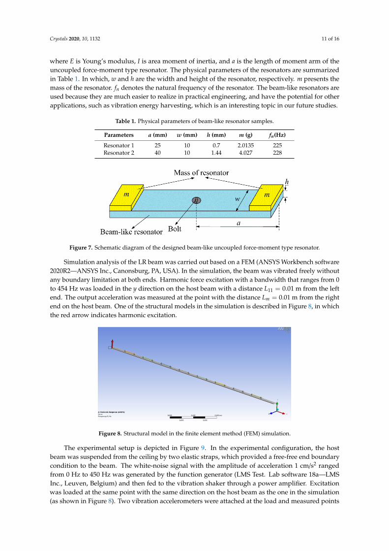
where E is Young’s modulus, I is area moment of inertia, and a is the length of moment arm of the uncoupled force-moment type resonator. The physical parameters of the resonators are summarized in Table 1. In which, w and h are the width and height of the resonator, respectively. m presents the mass of the resonator. fn denotes the natural frequency of the resonator. The beam-like resonators are used because they are much easier to realize in practical engineering, and have the potential for other applications, such as vibration energy harvesting, which is an interesting topic in our future studies.
Table 1. Physical parameters of beam-like resonator samples.
Parameters a (mm) w (mm) h (mm) m (g) fn(Hz) Resonator 1 25 10 0.7 2.0135 225 Resonator 2 40 10 1.44 4.027 228
Figure 6. (a) The upper and lower boundaries of the band-gaps as a function of (a) the mass and (b) themoment arm of a resonator with the same natural frequency of the resonator 227 Hz.
A finite Timoshenko LR beam suspended periodically with eight beam-like uncoupledforce-moment resonators was modeled and fabricated with the same physical properties as above.A numerical simulation and a vibration experiment were performed to verify the results calculatedwith the wave-based vibration analysis approach. The material of the beam-like resonator we designedis aluminum, and the model is shown in Figure 7. Similarly to the theoretical analysis, two sets ofresonators were chosen with the natural frequency around 227 Hz. The stiffness of the beam-likeresonator can be expressed as,
k =3EIa3 (68)
Crystals 2020, 10, 1132 11 of 16
where E is Young’s modulus, I is area moment of inertia, and a is the length of moment arm of theuncoupled force-moment type resonator. The physical parameters of the resonators are summarizedin Table 1. In which, w and h are the width and height of the resonator, respectively. m presents themass of the resonator. fn denotes the natural frequency of the resonator. The beam-like resonators areused because they are much easier to realize in practical engineering, and have the potential for otherapplications, such as vibration energy harvesting, which is an interesting topic in our future studies.
Table 1. Physical parameters of beam-like resonator samples.
Parameters a (mm) w (mm) h (mm) m (g) fn(Hz)
Resonator 1 25 10 0.7 2.0135 225Resonator 2 40 10 1.44 4.027 228Crystals 2020, 10, x FOR PEER REVIEW 11 of 16
Figure 7. Schematic diagram of the designed beam-like uncoupled force-moment type resonator.
Simulation analysis of the LR beam was carried out based on a FEM (ANSYS Workbench software 2020R2—ANSYS Inc., Canonsburg, PA, USA). In the simulation, the beam was vibrated freely without any boundary limitation at both ends. Harmonic force excitation with a bandwidth that ranges from 0 to 454 Hz was loaded in the y direction on the host beam with a distance =0.01 m from the left end. The output acceleration was measured at the point with the distance =0.01 m from the right end on the host beam. One of the structural models in the simulation is described in Figure 8, in which the red arrow indicates harmonic excitation.
Figure 8. Structural model in the finite element method (FEM) simulation.
The experimental setup is depicted in Figure 9. In the experimental configuration, the host beam was suspended from the ceiling by two elastic straps, which provided a free-free end boundary condition to the beam. The white-noise signal with the amplitude of acceleration 1 cm/s2 ranged from 0 Hz to 450 Hz was generated by the function generator (LMS Test. Lab software 18a—LMS Inc., Leuven, Belgium) and then fed to the vibration shaker through a power amplifier. Excitation was loaded at the same point with the same direction on the host beam as the one in the simulation (as shown in Figure 8). Two vibration accelerometers were attached at the load and measured points on the LR beam to measure the input and output accelerations, respectively. One period of a test sample in the experiment is presented in Figure 10. The mass of the resonator was realized by an aluminum block.
Figure 7. Schematic diagram of the designed beam-like uncoupled force-moment type resonator.
Simulation analysis of the LR beam was carried out based on a FEM (ANSYS Workbench software2020R2—ANSYS Inc., Canonsburg, PA, USA). In the simulation, the beam was vibrated freely withoutany boundary limitation at both ends. Harmonic force excitation with a bandwidth that ranges from 0to 454 Hz was loaded in the y direction on the host beam with a distance L11 = 0.01 m from the leftend. The output acceleration was measured at the point with the distance Lm = 0.01 m from the rightend on the host beam. One of the structural models in the simulation is described in Figure 8, in whichthe red arrow indicates harmonic excitation.
Crystals 2020, 10, x FOR PEER REVIEW 11 of 16
Figure 7. Schematic diagram of the designed beam-like uncoupled force-moment type resonator.
Simulation analysis of the LR beam was carried out based on a FEM (ANSYS Workbench software 2020R2—ANSYS Inc., Canonsburg, PA, USA). In the simulation, the beam was vibrated freely without any boundary limitation at both ends. Harmonic force excitation with a bandwidth that ranges from 0 to 454 Hz was loaded in the y direction on the host beam with a distance =0.01 m from the left end. The output acceleration was measured at the point with the distance =0.01 m from the right end on the host beam. One of the structural models in the simulation is described in Figure 8, in which the red arrow indicates harmonic excitation.
Figure 8. Structural model in the finite element method (FEM) simulation.
The experimental setup is depicted in Figure 9. In the experimental configuration, the host beam was suspended from the ceiling by two elastic straps, which provided a free-free end boundary condition to the beam. The white-noise signal with the amplitude of acceleration 1 cm/s2 ranged from 0 Hz to 450 Hz was generated by the function generator (LMS Test. Lab software 18a—LMS Inc., Leuven, Belgium) and then fed to the vibration shaker through a power amplifier. Excitation was loaded at the same point with the same direction on the host beam as the one in the simulation (as shown in Figure 8). Two vibration accelerometers were attached at the load and measured points on the LR beam to measure the input and output accelerations, respectively. One period of a test sample in the experiment is presented in Figure 10. The mass of the resonator was realized by an aluminum block.
Figure 8. Structural model in the finite element method (FEM) simulation.
The experimental setup is depicted in Figure 9. In the experimental configuration, the hostbeam was suspended from the ceiling by two elastic straps, which provided a free-free end boundarycondition to the beam. The white-noise signal with the amplitude of acceleration 1 cm/s2 rangedfrom 0 Hz to 450 Hz was generated by the function generator (LMS Test. Lab software 18a—LMSInc., Leuven, Belgium) and then fed to the vibration shaker through a power amplifier. Excitationwas loaded at the same point with the same direction on the host beam as the one in the simulation(as shown in Figure 8). Two vibration accelerometers were attached at the load and measured points

Crystals 2020, 10, 1132 12 of 16
on the LR beam to measure the input and output accelerations, respectively. One period of a testsample in the experiment is presented in Figure 10. The mass of the resonator was realized by analuminum block.Crystals 2020, 10, x FOR PEER REVIEW 12 of 16
Figure 9. Experimental setup for measuring the input and output accelerations near the two ends of the host beam.
Figure 10. One period of the test specimens.
Figure 11a,b show the numerical and measured frequency respond functions (FRFs) of the LR beam with periodic resonator 1 and resonator 2, respectively. Consider the propagation attenuation of the wave in the experiment, the flexural vibration band-gap in the measured transmission frequency respond curve is defined as the frequency range below −10 dB, while the one is defined below 0 dB line for the theoretical curves. Thus, the measured band-gap ranges are 206~245 Hz (resonator 1) and 187~285 Hz (resonator 2), respectively. The measured and simulated band-gaps show good agreement with the theoretical results obtained through the wave-based vibration analysis approach. Moreover, the influence of mass and length of the moment arm of the resonator on the width of the band-gaps is verified by the measured results. Comparing the curves of Figure 11a,b (solid lines), the width of band-gap is broadened about 151% when a 100% increase in the mass and 60% increase in the length of moment arm of the resonator occurs. The result demonstrates the method to obtain wide band-gaps easily in the low-frequency range for the LR beam suspended with an uncoupled force-moment type resonator in practical applications.
Figure 9. Experimental setup for measuring the input and output accelerations near the two ends ofthe host beam.
Crystals 2020, 10, x FOR PEER REVIEW 12 of 16
Figure 9. Experimental setup for measuring the input and output accelerations near the two ends of the host beam.
Figure 10. One period of the test specimens.
Figure 11a,b show the numerical and measured frequency respond functions (FRFs) of the LR beam with periodic resonator 1 and resonator 2, respectively. Consider the propagation attenuation of the wave in the experiment, the flexural vibration band-gap in the measured transmission frequency respond curve is defined as the frequency range below −10 dB, while the one is defined below 0 dB line for the theoretical curves. Thus, the measured band-gap ranges are 206~245 Hz (resonator 1) and 187~285 Hz (resonator 2), respectively. The measured and simulated band-gaps show good agreement with the theoretical results obtained through the wave-based vibration analysis approach. Moreover, the influence of mass and length of the moment arm of the resonator on the width of the band-gaps is verified by the measured results. Comparing the curves of Figure 11a,b (solid lines), the width of band-gap is broadened about 151% when a 100% increase in the mass and 60% increase in the length of moment arm of the resonator occurs. The result demonstrates the method to obtain wide band-gaps easily in the low-frequency range for the LR beam suspended with an uncoupled force-moment type resonator in practical applications.
Figure 10. One period of the test specimens.
Figure 11a,b show the numerical and measured frequency respond functions (FRFs) of the LRbeam with periodic resonator 1 and resonator 2, respectively. Consider the propagation attenuation ofthe wave in the experiment, the flexural vibration band-gap in the measured transmission frequencyrespond curve is defined as the frequency range below −10 dB, while the one is defined below 0 dBline for the theoretical curves. Thus, the measured band-gap ranges are 206~245 Hz (resonator 1) and187~285 Hz (resonator 2), respectively. The measured and simulated band-gaps show good agreementwith the theoretical results obtained through the wave-based vibration analysis approach. Moreover,the influence of mass and length of the moment arm of the resonator on the width of the band-gapsis verified by the measured results. Comparing the curves of Figure 11a,b (solid lines), the width ofband-gap is broadened about 151% when a 100% increase in the mass and 60% increase in the length ofmoment arm of the resonator occurs. The result demonstrates the method to obtain wide band-gapseasily in the low-frequency range for the LR beam suspended with an uncoupled force-moment typeresonator in practical applications.

Crystals 2020, 10, 1132 13 of 16Crystals 2020, 10, x FOR PEER REVIEW 13 of 16
Figure 11. The numerical and measured frequency response curves of (a) resonator 1, and (b) resonator 2.
Note that there are some extra resonance peaks in the measured results (see solid lines in Figure 11a, near 60, 260, 280, and 356 Hz, and in Figure 11b, near 60, 96, 115, and 153 Hz). It is because the uncoupled force-moment type resonator in our experiment is realized by a beam-like structure, which provides more vibration mode shapes than a simple spring-mass resonator, such as transverse deflection and rotation. It is also verified by the extra resonance peaks in the simulated curves obtained from FEM (see the dot dash line in Figure 11a,b). Because the band-gaps of the LR beam are the most important properties we were concerned about in practical applications, and all the extra resonance peaks are either near or below the 0 dB line, the unconformities are negligible.
To better understand the behavior of the structure, four points on the FRF curves in Figure 11 were selected to analyze the steady-state vibration profiles of the LR beam as presented in Figure 12. Two methods were used in Figure 12 as a comparison. The results show good agreement between vibration profiles and frequencies. There are small differences in the frequencies obtained by the two methods. This expected difference, as discussed above, is because the uncoupled force-moment type resonator in the simulation is realized by a beam-like structure, which provides more complex stiffness than a simple spring-mass resonator. Despite the expected difference, the results obtained from wave-based approach and FEM exhibit good agreement. Figure 12a–c present the vibration profiles at the resonance peaks A, B, and C. No obvious vibration attenuation along the structure can be observed on the vibration profiles. Figure 12d shows the vibration profiles inside the band-gap (around 120 Hz), the vibration amplitude at the right end of the LR beam is very small in comparison with that of the left end (excitation point). The vibration is highly localized close to the left end of the structure and is sharply attenuated along the structure, which presents as a band-gap.
Figure 11. The numerical and measured frequency response curves of (a) resonator 1, and (b) resonator 2.
Note that there are some extra resonance peaks in the measured results (see solid lines in Figure 11a,near 60, 260, 280, and 356 Hz, and in Figure 11b, near 60, 96, 115, and 153 Hz). It is because theuncoupled force-moment type resonator in our experiment is realized by a beam-like structure, whichprovides more vibration mode shapes than a simple spring-mass resonator, such as transverse deflectionand rotation. It is also verified by the extra resonance peaks in the simulated curves obtained from FEM(see the dot dash line in Figure 11a,b). Because the band-gaps of the LR beam are the most importantproperties we were concerned about in practical applications, and all the extra resonance peaks areeither near or below the 0 dB line, the unconformities are negligible.
To better understand the behavior of the structure, four points on the FRF curves in Figure 11were selected to analyze the steady-state vibration profiles of the LR beam as presented in Figure 12.Two methods were used in Figure 12 as a comparison. The results show good agreement betweenvibration profiles and frequencies. There are small differences in the frequencies obtained by thetwo methods. This expected difference, as discussed above, is because the uncoupled force-momenttype resonator in the simulation is realized by a beam-like structure, which provides more complexstiffness than a simple spring-mass resonator. Despite the expected difference, the results obtainedfrom wave-based approach and FEM exhibit good agreement. Figure 12a–c present the vibrationprofiles at the resonance peaks A, B, and C. No obvious vibration attenuation along the structure canbe observed on the vibration profiles. Figure 12d shows the vibration profiles inside the band-gap(around 120 Hz), the vibration amplitude at the right end of the LR beam is very small in comparisonwith that of the left end (excitation point). The vibration is highly localized close to the left end of thestructure and is sharply attenuated along the structure, which presents as a band-gap.

Crystals 2020, 10, 1132 14 of 16Crystals 2020, 10, x FOR PEER REVIEW 14 of 16
Figure 12. Steady-state vibration profiles obtained using the wave-based analysis approach and the FEM at the frequencies by the points (a) A, (b) B, (c) C, and (d) D in Figure 11a.
5. Concluding Remarks
In this paper, a finite Timoshenko LR beam carrying periodic 2-DOF uncoupled force-moment resonators is studied based on a wave-based vibration analysis approach. In formulating the system consisting of a host beam and uncoupled force-moment resonators, each resonator is considered as a source of an external transverse force and a bending moment to the beam. At each point that the resonator was attached, the reflected and transmitted coefficients can be easily assembled as a unit set of equations, which provides an accuracy and efficiency method in design and analysis of a finite Timoshenko LR beam. In addition, the parametric study is investigated to provide a promising method to broaden the low-frequency band-gap, such as adding the mass and length of moment arm of the resonator. Two sets of beam-like resonator samples are fabricated and measured to validate the accuracy of the proposed wave-based analysis method in analyzing frequency response functions of the LR beam. Vibration profiles acquired from wave-based analysis approach and FEM both show the resonance peak and band-gap vibration behavior of the LR beam. Theoretical calculation with the wave-based approach, numerical simulation using FEM, and the experiment all indicate the existence of a low frequency vibration band-gap in the LR beam. Results of this study prove that the wave-base vibration analysis approach is a powerful analytical tool in solving complex vibration problem in periodic LR structures. Future work can apply the proposed method to study the band-gap properties of 2-dimension and 3-dimension LR structures.
Figure 12. Steady-state vibration profiles obtained using the wave-based analysis approach and theFEM at the frequencies by the points (a) A, (b) B, (c) C, and (d) D in Figure 11a.
5. Concluding Remarks
In this paper, a finite Timoshenko LR beam carrying periodic 2-DOF uncoupled force-momentresonators is studied based on a wave-based vibration analysis approach. In formulating the systemconsisting of a host beam and uncoupled force-moment resonators, each resonator is consideredas a source of an external transverse force and a bending moment to the beam. At each point thatthe resonator was attached, the reflected and transmitted coefficients can be easily assembled as aunit set of equations, which provides an accuracy and efficiency method in design and analysis of afinite Timoshenko LR beam. In addition, the parametric study is investigated to provide a promisingmethod to broaden the low-frequency band-gap, such as adding the mass and length of moment armof the resonator. Two sets of beam-like resonator samples are fabricated and measured to validate theaccuracy of the proposed wave-based analysis method in analyzing frequency response functions ofthe LR beam. Vibration profiles acquired from wave-based analysis approach and FEM both show theresonance peak and band-gap vibration behavior of the LR beam. Theoretical calculation with thewave-based approach, numerical simulation using FEM, and the experiment all indicate the existenceof a low frequency vibration band-gap in the LR beam. Results of this study prove that the wave-basevibration analysis approach is a powerful analytical tool in solving complex vibration problem inperiodic LR structures. Future work can apply the proposed method to study the band-gap propertiesof 2-dimension and 3-dimension LR structures.

Crystals 2020, 10, 1132 15 of 16
Author Contributions: This paper represents a result of collaborative teamwork. H.L. developed the concept andprepared the manuscript. Y.Z. provided constructive suggestions and revised the manuscript. The two authorscontributed equally to this work. All authors have read and agreed to the published version of the manuscript.
Funding: This work was funded by the China Scholarship Council under grant number 201906085003.
Conflicts of Interest: The authors declare no conflict of interest.
References
1. Mead, D.J. Wave propagation in continuous periodic structures: Research contributions from Southampton.J. Sound Vib. 1996, 190, 495–524. [CrossRef]
2. Sigalas, M.M.; Economou, E. Elastic and acoustic wave band structure. J. Sound Vib. 1992, 158, 377–382.[CrossRef]
3. Kushwaha, M.S.; Halevi, P.; Dobrzynski, L.; Djafari-Rouhani, B. Acoustic band structure of periodic elasticcomposites. Phys. Rev. Lett. 1993, 71, 2022–2025. [CrossRef] [PubMed]
4. Cao, D.; Hu, W.; Gao, Y.; Guo, X. Vibration and energy harvesting performance of a piezoelectric phononiccrystal beam. Smart Mater. Struct. 2019, 28, 085014. [CrossRef]
5. Qiao, H.; Li, Q.S.; Li, G.Q. Vibratory characteristics of flexural non-uniform Euler–Bernoulli beams carryingan arbitrary number of spring–mass systems. Int. J. Mech. Sci. 2002, 44, 725–743. [CrossRef]
6. Yu, D.; Liu, Y.; Zhao, H.; Wang, G.; Qiu, J. Flexural vibration band gaps in Euler-Bernoulli beams with locallyresonant structures with two degrees of freedom. Phys. Rev. B 2006, 73, 064301. [CrossRef]
7. Yu, D.; Liu, Y.; Wang, G.; Zhao, H.; Qiu, J. Flexural vibration band gaps in Timoshenko beams with locallyresonant structures. J. Appl. Phys. 2006, 100, 124901. [CrossRef]
8. Wang, M.Y.; Wang, X. Frequency band structure of locally resonant periodic flexural beams suspended withforce-moment resonators. J. Phys. D Appl. Phys. 2013, 46, 255502. [CrossRef]
9. Chen, S.; Song, Y.; Zhang, H. Wave Propagation in L-Shape Beams with Piezoelectric Shunting Arrays.Shock Vib. 2019, 2019, 1–14. [CrossRef]
10. Zhou, J.; Dou, L.; Wang, K.; Xu, D.; Ouyang, H. A nonlinear resonator with inertial amplification for verylow-frequency flexural wave attenuations in beams. Nonlinear Dyn. 2019, 96, 647–665. [CrossRef]
11. Xiao, Y.; Wen, J.; Wang, G.; Wen, X. Theoretical and experimental study of locally resonant and Braggband gaps in flexural beams carrying periodic arrays of beam-like resonators. ASME J. Vib. Acoust. 2013,135, 041006. [CrossRef]
12. Hajhosseini, M.; Rafeeyan, M.; Ebrahimi, S. Vibration band gap analysis of a new periodic beam model usingGDQR method. Mech. Res. Commun. 2017, 79, 43–50. [CrossRef]
13. Liang, X.; Wang, T.; Jiang, X.; Liu, Z.; Ruan, Y.; Deng, Y. A Numerical Method for Flexural Vibration BandGaps in A Phononic Crystal Beam with Locally Resonant Oscillators. Crystals 2019, 9, 293. [CrossRef]
14. Lepidi, M.; Bacigalupo, A. Wave propagation properties of one-dimensional acoustic metamaterials withnonlinear diatomic microstructure. Nonlinear Dyn. 2019, 98, 2711–2735. [CrossRef]
15. Wu, X.; Li, Y.; Zuo, S. The study of a locally resonant beam with aperiodic mass distribution. Appl. Acoust.2020, 165, 107306. [CrossRef]
16. Mei, C. A Wave-Based Analytical Solution to Free Vibrations in a Combined Euler–Bernoulli Beam/Frameand a Two-Degree-of-Freedom Spring–Mass System. J. Vib. Acoust. 2018, 140, 061001. [CrossRef]
17. Mei, C. Wave Analysis of In-Plane Vibrations of H- and T-shaped Planar Frame Structures. J. Vib. Acoust.2008, 130, 061004. [CrossRef]
18. Mei, C. In-plane Vibrations of Classical Planar Frame Structures—An Exact Wave-based Analytical Solution.J. Vib. Control. 2010, 16, 1265–1285. [CrossRef]
19. Mei, C. Wave Analysis of In-Plane Vibrations of L-Shaped and Portal Planar Frame Structures. J. Vib. Acoust.2012, 134, 021011. [CrossRef]
20. Mei, C. Free vibration analysis of classical single-story multi-bay planar frames. J. Vib. Control. 2012, 19,2022–2035. [CrossRef]
21. Mei, C.; Mace, B.R. Wave Reflection and Transmission in Timoshenko Beams and Wave Analysis ofTimoshenko Beam Structures. J. Vib. Acoust. 2005, 127, 382–394. [CrossRef]
22. Leamy, M.J. Exact wave-based Bloch analysis procedure for investigating wave propagation intwo-dimensional periodic lattices. J. Sound Vib. 2012, 331, 1580–1596. [CrossRef]

Crystals 2020, 10, 1132 16 of 16
23. Salleh, H.; Brennan, M.J. Control of flexural waves on a beam using a vibration neutraliser: Effects of differentattachment configurations. J. Sound Vib. 2007, 303, 501–514. [CrossRef]
24. Graff, K.F. Wave Motion in Elastic Soilds; Ohio State University Press: Columbus, OH, USA, 1975.
Publisher’s Note: MDPI stays neutral with regard to jurisdictional claims in published maps and institutionalaffiliations.
© 2020 by the authors. Licensee MDPI, Basel, Switzerland. This article is an open accessarticle distributed under the terms and conditions of the Creative Commons Attribution(CC BY) license (http://creativecommons.org/licenses/by/4.0/).


![Vibration of Timoshenko Beam-Soil Foundation Interaction by …jsm.iau-arak.ac.ir/article_677316_9f91814aa7024a7daa258... · 2 days ago · span Timoshenko beam. Banerjee [15] investigated](https://static.fdocuments.net/doc/165x107/60c0f04fc2fd995b4c03c833/vibration-of-timoshenko-beam-soil-foundation-interaction-by-jsmiau-arakacirarticle6773169f91814aa7024a7daa258.jpg)