
Vibration analysis of rotating tapered Timoshenko...
11
Shock and Vibration 13 (2006) 117–126 117 IOS Press Vibration analysis of rotating tapered Timoshenko beams by a new finite element model Bulent Yardimoglu Department of Mechanical Engineering, Izmir Institute of Technology, 35430, Urla, Izmir, Turkey Tel.: +90 232 750 6599; E-mail: [email protected] Received 5 August 2005 Revised 7 October 2005 Abstract. A new finite element model is developed and subsequently used for transverse vibrations of tapered Timoshenko beams with rectangular cross-section. The displacement functions of the finite element are derived from the coupled displacement field (the polynomial coefficients of transverse displacement and cross-sectional rotation are coupled through consideration of the differential equations of equilibrium) approach by considering the tapering functions of breadth and depth of the beam. This procedure reduces the number of nodal variables. The new model can also be used for uniform beams. The stiffness and mass matrices of the finite element model are expressed by using the energy equations. To confirm the accuracy, efficiency, and versatility of the new model, a semi-symbolic computer program in MATLAB is developed. As illustrative examples, the bending natural frequencies of non-rotating/rotating uniform and tapered Timoshenko beams are obtained and compared with previously published results and the results obtained from the finite element models of solids created in ABAQUS. Excellent agreement is found between the results of new finite element model and the other results. 1. Introduction It is well known that when the beams are stubby or when the higher modes are of interest in bending vibrations, Timoshenko beam theory is employed. The effects of shear deformation and rotary inertia are taken into account in this theory which is expressed by two coupled partial differential equations. For free vibration of uniform beams, the coupled equations can be reduced to one single equation since the coefficients appeared in this set of equations are constants. However, for tapered beams, the aforementioned coefficients are variables. On the other hand, consideration of the rotational effects on the beam vibrations causes addition of a term with variable coefficient in those equations. Due to the variable coefficients, it is in general difficult to obtain exact solutions of vibration problems of rotating Timoshenko beams with varying cross-section. Therefore, selecting a number of cross-section variation functions, the problem has been solved mainly by numerical or approximate methods. A carefully selected sample of the relevant literature is as follows: Exact solution for the vibration of simply supported uniform Timoshenko beam can be found in some textbooks on vibration such as reference [9]. Huang [7] presented frequency and normal mode equations for flexural vibrations of uniform Timoshenko beams with six common boundary conditions. Davis et al. [4] derived a Timoshenko beam finite element model having two nodes of two degrees of freedoms consisting of transverse displacement and cross-sectional rotation by solving the static equilibrium equations of an infinitesimal unloaded element. Dawe [5] presented a three-noded Timoshenko beam element based on the coupled displacement field; the lateral deflection function is linked to the cross-sectional rotation function by satisfying the unloaded and homogeneous form of the coupled differential equations. Nodal freedoms of the latter are the same ISSN 1070-9622/06/$17.00 © 2006 – IOS Press and the authors. All rights reserved
Transcript of Vibration analysis of rotating tapered Timoshenko...

Shock and Vibration 13 (2006) 117–126 117IOS Press
Vibration analysis of rotating taperedTimoshenko beams by a new finite elementmodel
Bulent YardimogluDepartment of Mechanical Engineering, Izmir Institute of Technology, 35430, Urla, Izmir, TurkeyTel.: +90 232 750 6599; E-mail: [email protected]
Received 5 August 2005
Revised 7 October 2005
Abstract. A new finite element model is developed and subsequently used for transverse vibrations of tapered Timoshenko beamswith rectangular cross-section. The displacement functions of the finite element are derived from the coupled displacement field(the polynomial coefficients of transverse displacement and cross-sectional rotation are coupled through consideration of thedifferential equations of equilibrium) approach by considering the tapering functions of breadth and depth of the beam. Thisprocedure reduces the number of nodal variables. The new model can also be used for uniform beams. The stiffness and massmatrices of the finite element model are expressed by using the energy equations. To confirm the accuracy, efficiency, andversatility of the new model, a semi-symbolic computer program in MATLAB is developed. As illustrative examples, thebending natural frequencies of non-rotating/rotating uniform and tapered Timoshenko beams are obtained and compared withpreviously published results and the results obtained from the finite element models of solids created in ABAQUS. Excellentagreement is found between the results of new finite element model and the other results.
1. Introduction
It is well known that when the beams are stubby or when the higher modes are of interest in bending vibrations,Timoshenko beam theory is employed. The effects of shear deformation and rotary inertia are taken into account inthis theory which is expressed by two coupled partial differential equations. For free vibration of uniform beams,the coupled equations can be reduced to one single equation since the coefficients appeared in this set of equationsare constants. However, for tapered beams, the aforementioned coefficients are variables. On the other hand,consideration of the rotational effects on the beam vibrations causes addition of a term with variable coefficientin those equations. Due to the variable coefficients, it is in general difficult to obtain exact solutions of vibrationproblems of rotating Timoshenko beams with varying cross-section. Therefore, selecting a number of cross-sectionvariation functions, the problem has been solved mainly by numerical or approximate methods. A carefully selectedsample of the relevant literature is as follows:
Exact solution for the vibration of simply supported uniform Timoshenko beam can be found in some textbookson vibration such as reference [9]. Huang [7] presented frequency and normal mode equations for flexural vibrationsof uniform Timoshenko beams with six common boundary conditions.
Davis et al. [4] derived a Timoshenko beam finite element model having two nodes of two degrees of freedomsconsisting of transverse displacement and cross-sectional rotation by solving the static equilibrium equations of aninfinitesimal unloaded element. Dawe [5] presented a three-noded Timoshenko beam element based on the coupleddisplacement field; the lateral deflection function is linked to the cross-sectional rotation function by satisfying theunloaded and homogeneous form of the coupled differential equations. Nodal freedoms of the latter are the same
ISSN 1070-9622/06/$17.00 © 2006 – IOS Press and the authors. All rights reserved

118 B. Yardimoglu / Vibration analysis of rotating tapered Timoshenko beams by a new finite element model
as the first. Alternatively, Thomas et al. [19] presented a Timoshenko beam element having six degrees of freedom,comprising the transverse displacement, the cross-sectional rotation, and the shear deformation at the elementends. In order to analyze the in-plane (lead-lag) and out-of-plane (flapping) vibration characteristics of the rotatinguniform Timoshenko beams, Yokoyama [22] developed a two-noded finite element model by means of a staticalmoment-shear equilibrium condition and the relation between cross-sectional rotation and shear deformation; thenodal freedoms are the transverse displacement assumed as a cubic displacement distribution and the cross-sectionalrotation.
A number of papers for vibration analysis of tapered Timoshenko beams by finite element method have beenpublished. To [20] used the finite element model given by Thomas et al. [19] for vibration analysis of a linearlytapered Timoshenko beam. Bazoune and Khulief [1] referred to Yokoyama [22] and Przemieniecki [17] for elementalshape functions in their study on vibration of rotating linearly tapered Timoshenko beams. Likewise, Mulmuleet al. [14] employed the shape function given by Yokoyama [22] for flexural vibration of rotating linearly taperedTimoshenko beams. Rao and Gupta [18] derived the element mass and stiffness matrices for a rotating twisted andtapered Timoshenko beam element by considering bending deflection, shear deflection, bending slope, and shearslope as nodal freedoms. The displacements functions for bending and shear are assumed to be polynomials of thirddegree. However, cross-sectional tapering functions are not taken into account in the derivation of the finite elementdisplacement or shape functions used in the aforementioned models, while they are considered as geometricalproperties in energy integrals. Cleghorn and Tabarrok [3] developed a two-noded finite element formulation for atapered Timoshenko beam for free lateral vibration analysis. In their model, the shape functions are obtained fromthe homogeneous solution of the governing equations for static deflection. They judged that the inclusion of theshear strain in nodal variables as in model used by To [20] is superfluous, and then selected the lateral displacementand rotation of cross-section as the nodal variables. One of the drawbacks of this model is the tapering functionbased on the cross-sectional area. Another one is the removable singularity for the case of a uniform beam. Forthe latter, Cleghorn and Tabarrok [3] used the modifications by replacing the logarithmic terms with Taylor series inpowers of singularity parameter. However, in general, the variation of the cross sections of the beams is defined byusing their breadth and/or depth not by cross-sectional area. On the other hand, the usage of series expansions cancause to lose the accuracy of the results.
The vibration problems of tapered Timoshenko beams have been also studied by other methods such as the modifieddifferential quadrature method [2], the dynamic discretization technique [6], the spline interpolation technique [10],the transfer matrix method [11], and the method of Frobenius [12]. Among these studies, Lee and Lin [12] shown thatif the coefficient of the reduced differential equation are in polynomial form, then the exact fundamental solutionscan be obtained.
From the foregoing discussion on the finite element formulation, it is apparent that there is no available shapefunctions incorporated with the taper parameter(s) based on the breadth and/or depth of the cross-section of thetapered beam. Therefore, the main purpose of this paper is to propose the novel finite element model based on thecoupled displacement field incorporating the taper functions of breadth and depth of the rectangular cross-sectionedTimoshenko beams. The new finite element model derived in this study has exact stiffness matrix, but approximatemass matrix due to the usage of static equilibrium condition as in references [4,5]. It is clear that the usage of theapproximate mass matrix requires an increase in the number of elements required for a desired accuracy. However,this is amply compensated by the simplicity of the mathematical analysis it provides [16]. Finally, the new model isverified for out-of-plane vibration of non-rotating/rotating uniform and tapered Timoshenko beams by comparisonsof the results obtained from the semi-symbolic code of the present model developed in MATLAB with the resultsavailable in the literature and results obtained from the solid models in ABAQUS, respectively. The all results aregiven in tabular form to show the accuracy of the present new model clearly.
2. Derivation of the finite element displacement functions
The coupled partial differential equations of motion for a Timoshenko beam with variable cross-section are givenin references [15,16]. The homogeneous form of these equations are written as follows:

B. Yardimoglu / Vibration analysis of rotating tapered Timoshenko beams by a new finite element model 119
h(z)
b(z)
x
y
z
Ω
Fig. 1. Rotating tapered beam.
dM(z)dz
+ V (z) = 0, (1)
dV (z)dz
= 0 (2)
where
M(z) = EI(z)dθ
dz, (3)
V (z) = kA(z)G(
dv
dz− θ
)(4)
The notation used throughout this paper is listed in the Appendix. Equation (2) gives a constant shear force alongthe length of the beam. Hence, considering this constant shear force in Eq. (1), bending moment is obtained byintegration as
M(z) = C1z + C2. (5)
By substituting Eq. (5) into Eq. (3), and integrating, the cross-sectional rotation is expressed as
θ(z) =∫
1EI(z)
(C1z + C2) dz (6)
Then, substituting Eq. (6) along with Eqs (3) and (4) into Eq. (1), and integrating yields
v(z) =∫ {
θ − 1kA(z)G
d
dz
[EI(z)
dθ
dz
]}dz (7)
Now, the rotating tapered Timoshenko beam shown in Fig. 1 is considered to indicate the cross-sectional parame-ters. The breadth and depth of the beam are selected as follows:
b(z) = bcz−m, (8)
h(z) = hcz−n (9)
where bc = brzmr and hc = hrz
nr . Hence, the cross-sectional area of the beam can be written as
A(z) = Acz−r (10)
where Ac = bchc and r = m + n.Also, the area moment of inertia of the cross-section about x axis can be expressed as

120 B. Yardimoglu / Vibration analysis of rotating tapered Timoshenko beams by a new finite element model
I(z) = Ixxcz−p (11)
where Ixxc = bch3c/12 and p = m + 3n.
Substituting Eq. (11) into Eq. (6), and integrating yields
θ(z, t) = θ0(t) + θ1(t)zp+1 + θ2(t)zp+2 (12)
Also, substituting Eqs (10)–(12) into Eq. (7), and integrating yields
v(z, t) = v0(t) + v1(t)z + v2(t)zp+2 + v3(t)(zp+3 − crzr+1) (13)
where
v1(t) = θ0(t), v2(t) = θ1(t)/(2 + p), v3(t) = θ2(t)/(3 + p) (14)
cr = EIxxc(2 + p)(3 + p)/(kGAc(1 + r)) (15)
It is convenient to express the relationships between the coefficients of the cross-sectional rotation and of thetransverse displacement in the matrix form:
{cθ} = [B] {cv} (16)
where
{cθ} = {θ0(t) θ1(t) θ2(t)}T (17)
{cv} = {v0(t) v1(t) v2(t) v3(t)}T (18)
[B] =
⎡⎣0 1 0 0
0 0 2 + p 00 0 0 3 + p
⎤⎦ (19)
The [B] matrix is termed as polynomial coefficients coupling matrix. On the other hand, the cross-sectionalrotation given in Eq. (12) may be written as follows:
θ(z, t) = [Pθ] {cθ} (20)
where
[Pθ] =[1 zp+1 zp+2
](21)
Also, the transverse displacement given in Eq. (13) may be expressed as follows:
v(z, t) = [Pv] {cv} (22)
where
[Pv] =[1 z zp+2 (zp+2 − crz
r+1)]
(23)
Now, the finite element model of a rotating tapered Timoshenko beam shown in Fig. 2 is considered. Nodalfreedoms of the new finite element are the transverse displacement and the cross-sectional rotation. Therefore, theelement displacement vector is given by
{qe} = {vI θI vII θII}T (24)
Then, by using Eqs (12)–(15), the element displacement vector can be expressed in terms of the polynomialcoefficient vector of transverse displacement as follows:
{qe} = [C] {cv} (25)
where

B. Yardimoglu / Vibration analysis of rotating tapered Timoshenko beams by a new finite element model 121
z
y
z z1
zr L
z2 Ω
I II
Fig. 2. Finite element model of rotating tapered Timoshenko beam.
[C] =
⎡⎢⎢⎣
1 z1 zp+21 zp+3
1 − crzr+11
0 1 (2 + p)zp+11 (3 + p)zp+2
1
1 z2 zp+22 zp+3
2 − crzr+12
0 1 (2 + p)zp+12 (3 + p)zp+2
2
⎤⎥⎥⎦ (26)
in which the matrix [C] is termed as “element displacement-polynomial coefficient matrix”. Finally, Eq. (20) canbe expressed by using Eqs (16) and (25) as
θ(z, t) = [Pθ] [B] [C]−1 {qe} (27)
and also, Eq. (22) can be expressed by using Eq. (25) as
v(z, t) = [Pv] [C]−1 {qe} (28)
3. Derivation of the finite element mass and stiffness matrices
The elastic potential energy of the tapered Timoshenko beam is given in references [15,16] by
Ue = 0.5∫ z2
z1
EI(z)(
dθ(z, t)dz
)2
dz + 0.5∫ z2
z1
kGA(z)(
dv(z, t)dz
− θ(z, t))2
dz (29)
By substituting Eqs (10), (11), (27), and (28) into Eq. (29) gives
Ue = 0.5 {qe}T [Ke] {qe} (30)
where
[Ke] = [C]−T [k] [C]−1 (31)
in which
[k] = [B]T{
E
∫ z2
z1
I(z) [P ′θ]
T [P ′θ] dz + kG
∫ z2
z1
A(z) [Pθ]T [Pθ] dz
}[B]
(32)
−kG
{[B]T
∫ z2
z1
A(z) [Pθ]T [P ′
v] dz +∫ z2
z1
A(z) [P ′v]T [Pθ] dz [B]
}+ kG
∫ z2
z1
A(z) [P ′v]T [P ′
v] dz
The symbol “ ′” used throughout this paper represents differentiation with respect to z. The geometric strainenergy due to centrifugal force is written as follows [15]:
Ug = 0.5∫ z2
z1
P (z)(
dv(z, t)dz
)2
dz (33)
where

122 B. Yardimoglu / Vibration analysis of rotating tapered Timoshenko beams by a new finite element model
P (z) =∫ zr+L
z
ρ A(z)Ω2z dz (34)
Similarly, by substituting Eq. (34) along with Eqs (10) and (28) into Eq. (33) leads to
Ug = 0.5 {qe}T [Se] {qe} (35)
where
[Se] = [C]−T [s] [C]−1 (36)
in which
[s] =∫ z2
z1
P (z) [P ′v]T [P ′
v] dz (37)
Finally, the kinetic energy of the tapered Timoshenko beam is expressed as follows [15,16]:
T = 0.5∫ z2
z1
ρ A(z)(
dv(z, t)dt
)2
dz + 0.5∫ z2
z1
ρ I(z)(
dθ(z, t)dt
)2
dz (38)
Similarly, by substituting Eqs (10), (11), (27), and (28) into Eq. (38) yields
T = 0.5 {q̇e}T [Me] {q̇e} (39)
where the overdot is the compact notation for differentiation with respect to time, and [M e] is
[Me] = [C]−T [m] [C]−1 (40)
in which
[m] = ρ
{ ∫ z2
z1
A(z) [Pv]T [Pv] dz + [B]T∫ z2
z1
I(z) [Pθ]T [Pθ] dz [B]
}(41)
4. Dynamic equilibrium equation and Solution technique
In order to obtain the natural frequencies for out-of-plane vibration of non-rotating/rotating uniform and taperedTimoshenko beams, the dynamic equilibrium equation is reduced to eigenvalue problem given below,(
([K] + [S]) − ω2[M ]) {q} = 0 (42)
Element elastic stiffness, geometric stiffness, and mass matrices given in Eqs (31), (36), and (40), respectively, areused directly in the semi-symbolic computer program developed in MATLAB for this study. To form the globalmatrices, calculated element matrices are assembled in the usual way, and then boundary conditions are applied asclamped at zr-free. The eigenvalue problem given in Eq. (42) is then solved.
5. Numerical results and discussion
The accuracy, efficiency, and versatility of the new finite element model are verified by the several examplesof the Timoshenko beam vibration problem. The first group of examples to be considered is the case of freevibration of non-rotating uniform Timoshenko beams. Solutions of the aforementioned problem by using a propernumber of elements are obtained to demonstrate the convergence pattern, compared with the exact results foundfrom the frequency equation given by Huang [7], and Huang and Kung [8], and then presented in Tables 1 and 2 forrg/L = 0.05 and rg/L = 0.1, respectively. The present finite element solutions with 14 elements for r g/L =0.05 and 16 elements for rg/L = 0.1 are converged to the exact solutions for the fourth frequency parameters withless than 1% error (% Error = 100*[Present/Exact-1] ). Furthermore, % errors of the present solutions for the firstfrequency parameters given in Tables 1 and 2 are extremely small.

B. Yardimoglu / Vibration analysis of rotating tapered Timoshenko beams by a new finite element model 123
Table 1Convergence pattern and comparison of frequency parameters for uniform Timo-shenko beam (rg/L = 0.05, zr/L = 3, E/G = 2.6, k = 0.85)
Frequency parameters λ First Second Third Fourth
Present N = 4 3.437327 19.278897 48.565736 85.450496Present N = 6 3.436809 19.200096 47.597646 83.123418Present N = 8 3.436640 19.173099 47.229024 81.490162Present N = 10 3.436565 19.160758 47.056972 80.690445Present N = 12 3.436524 19.154101 46.963417 80.249698Present N = 14 3.436500 19.150103 46.907017 79.982505Present N = 16 3.436484 19.147516 46.870425 79.808657Exact [7,8] 3.436434 19.139101 46.751022 79.239252% Error for N =14 0.001920 0.057486 0.333672 0.937986
Table 2Convergence pattern and comparison of frequency parameters for uniform Timo-shenko beam (rg /L = 0.1, zr /L = 3, E/G = 2.6, k = 0.85)
Frequency parameters λ First Second Third Fourth
Present N = 4 3.233589 14.745679 33.709784 53.748206Present N = 6 3.232099 14.628146 32.641472 51.237414Present N = 8 3.231583 14.585885 32.224311 49.982820Present N = 10 3.231346 14.566170 32.026774 49.365712Present N = 12 3.231217 14.555424 31.918554 49.022962Present N = 14 3.231139 14.548933 31.853031 48.814069Present N = 16 3.231089 14.544715 31.810404 48.677670Exact [7,8] 3.230925 14.530913 31.670669 48.228066% Error for N = 16 0.005077 0.094984 0.441213 0.932246
Table 3Comparison of frequency parameters for rotating uniform Timoshenkobeam (rg /L = 0.05, zr/L = 3, E/G = 2.6, k = 0.85, η = 10)
Frequency parameters λ First Second Third Fourth
Present N = 16 23.524 56.105 97.188 144.490Wang et al. [21] 23.514 56.072 97.011 143.815Yokoyama [22] N = 16 23.524 56.105 97.188 144.490Lee and Lin [13] 23.491 55.984 96.913 143.710
Table 4Comparison of frequency parameters for rotating uniform Timo-shenko beam (rg /L = 0.1, zr /L = 3, E/G = 2.6, k = 0.85, η =10)
Frequency parameters λ First Second Third Fourth
Present N = 16 23.050 45.598 67.716 73.076Wang et al. [21] 23.037 45.428 66.854 72.313Yokoyama [22] N = 16 23.050 45.598 67.716 73.076Lee and Lin [13] 22.938 44.781 66.287 71.967
The second group of examples deals with the out-of-plane vibration of the rotating uniform Timoshenko beams.In Tables 3 and 4, the present frequency parameters of rotating Timoshenko beams obtained by using 16 elementsare compared with the results given by Wang et al. [21], Yokoyama [22], and Lee and Lin [13]. Among these studies,while Wang et al. [21] used the extended Galerkin’s method, Lee and Lin [13] utilized the power series method.
The last group of examples is employed to evaluate the present finite element models for the cases of non-rotatingand rotating tapered Timoshenko beams. The two tapered beam models based on the physical and geometricalparameters given in Table 5 and 6 are considered. The out-of-plane natural frequencies of these beams are foundfrom the present finite element models by using 16 elements and from the solid finite element models created inABAQUS by using 390 hexahedral elements for reasonable rotational speeds based on the normal stress due to thecentrifugal force. The out-of-plane frequency parameters for rotating tapered Timoshenko beams obtained from the
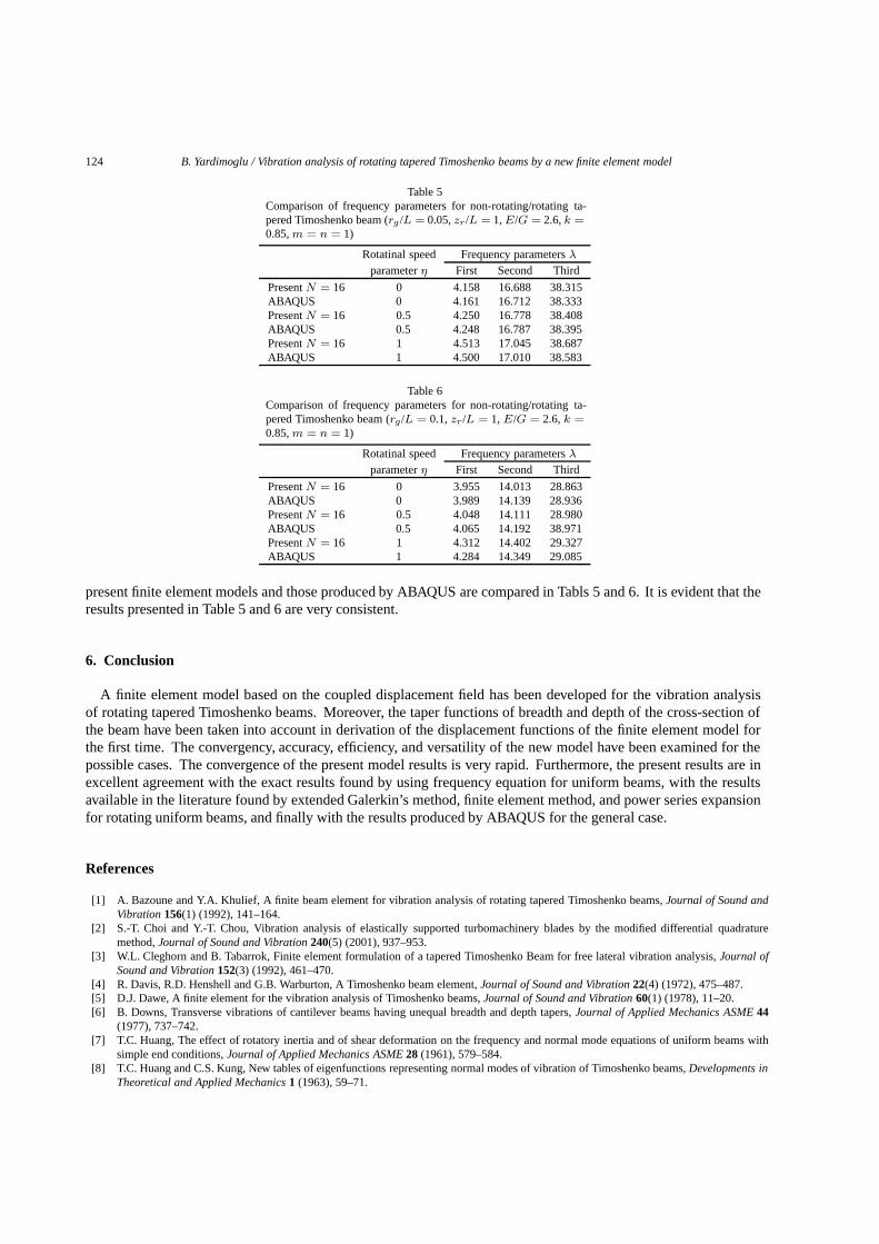
124 B. Yardimoglu / Vibration analysis of rotating tapered Timoshenko beams by a new finite element model
Table 5Comparison of frequency parameters for non-rotating/rotating ta-pered Timoshenko beam (rg /L = 0.05, zr/L = 1, E/G = 2.6, k =0.85, m = n = 1)
Rotatinal speed Frequency parameters λ
parameter η First Second Third
Present N = 16 0 4.158 16.688 38.315ABAQUS 0 4.161 16.712 38.333Present N = 16 0.5 4.250 16.778 38.408ABAQUS 0.5 4.248 16.787 38.395Present N = 16 1 4.513 17.045 38.687ABAQUS 1 4.500 17.010 38.583
Table 6Comparison of frequency parameters for non-rotating/rotating ta-pered Timoshenko beam (rg /L = 0.1, zr/L = 1, E/G = 2.6, k =0.85, m = n = 1)
Rotatinal speed Frequency parameters λ
parameter η First Second Third
Present N = 16 0 3.955 14.013 28.863ABAQUS 0 3.989 14.139 28.936Present N = 16 0.5 4.048 14.111 28.980ABAQUS 0.5 4.065 14.192 38.971Present N = 16 1 4.312 14.402 29.327ABAQUS 1 4.284 14.349 29.085
present finite element models and those produced by ABAQUS are compared in Tabls 5 and 6. It is evident that theresults presented in Table 5 and 6 are very consistent.
6. Conclusion
A finite element model based on the coupled displacement field has been developed for the vibration analysisof rotating tapered Timoshenko beams. Moreover, the taper functions of breadth and depth of the cross-section ofthe beam have been taken into account in derivation of the displacement functions of the finite element model forthe first time. The convergency, accuracy, efficiency, and versatility of the new model have been examined for thepossible cases. The convergence of the present model results is very rapid. Furthermore, the present results are inexcellent agreement with the exact results found by using frequency equation for uniform beams, with the resultsavailable in the literature found by extended Galerkin’s method, finite element method, and power series expansionfor rotating uniform beams, and finally with the results produced by ABAQUS for the general case.
References
[1] A. Bazoune and Y.A. Khulief, A finite beam element for vibration analysis of rotating tapered Timoshenko beams, Journal of Sound andVibration 156(1) (1992), 141–164.
[2] S.-T. Choi and Y.-T. Chou, Vibration analysis of elastically supported turbomachinery blades by the modified differential quadraturemethod, Journal of Sound and Vibration 240(5) (2001), 937–953.
[3] W.L. Cleghorn and B. Tabarrok, Finite element formulation of a tapered Timoshenko Beam for free lateral vibration analysis, Journal ofSound and Vibration 152(3) (1992), 461–470.
[4] R. Davis, R.D. Henshell and G.B. Warburton, A Timoshenko beam element, Journal of Sound and Vibration 22(4) (1972), 475–487.[5] D.J. Dawe, A finite element for the vibration analysis of Timoshenko beams, Journal of Sound and Vibration 60(1) (1978), 11–20.[6] B. Downs, Transverse vibrations of cantilever beams having unequal breadth and depth tapers, Journal of Applied Mechanics ASME 44
(1977), 737–742.[7] T.C. Huang, The effect of rotatory inertia and of shear deformation on the frequency and normal mode equations of uniform beams with
simple end conditions, Journal of Applied Mechanics ASME 28 (1961), 579–584.[8] T.C. Huang and C.S. Kung, New tables of eigenfunctions representing normal modes of vibration of Timoshenko beams, Developments in
Theoretical and Applied Mechanics 1 (1963), 59–71.
B. Yardimoglu / Vibration analysis of rotating tapered Timoshenko beams by a new finite element model 125
[9] D.J. Inman, Engineering Vibration, (Second edition), Prentice-Hall, New Jersey, 2001.[10] T. Irie, G. Yamada and I. Takahashi, Determination of the steady state response of a Timoshenko beam of varying cross-section by use of
the spline interpolation technique, Journal of Sound and Vibration 63(2) (1979), 287–295.[11] T. Irie, G. Yamada and I. Takahashi, Vibration and stability of a non-uniform Timoshenko beam subjected to a follower force, Journal of
Sound and Vibration 70(4) (1980), 503–512.[12] S.Y. Lee and S.M. Lin, Exact vibration Solutions for nonuniform Timoshenko beams with attachments, AIAA Journal 30(12) (1992),
2930–2934.[13] S.Y. Lee and S.M. Lin, Bending vibrations of rotating nonuniform Timoshenko beams with an elastically restrained root, Journal of Applied
Mechanics ASME 61 (1994), 949–955.[14] S. Mulmule, G. Singh and G. Venkateswara Rao, Flexural vibration of rotating tapered Timoshenko beams, Journal of Sound and Vibration
160(2) (1993), 372–377.[15] L. Meirovitch, Analytical Methods in Vibrations, Macmillan, New York, 1967.[16] M. Petyt, Introduction to Finite Element Vibration Analysis, Cambridge University Press, Cambridge, 1990.[17] J.S. Przemieniecki, Theory of Matrix Structural Analysis, McGraw-Hill, New York, 1968.[18] S.S. Rao and R.S. Gupta, Finite element vibration analysis of rotating Timoshenko beams, Journal of Sound and Vibration 242(1) (2001),
103–124.[19] D.L. Thomas, J.M. Wilson and R.R. Wilson, Timoshenko beam finite elements, Journal of Sound and Vibration 31(3) (1973), 315–330.[20] C.W.S. To, A linearly tapered beam finite element incorporating shear deformation and rotary inertia for vibration analysis, Journal of
Sound and Vibration 78(4) (1981), 475–484.[21] J.T.S. Wang, O. Mahrenholtz and J. Bohm, Extended Galerkin’s method for rotating beam vibrations using Legendre Polynomials, Solid
Mechanics Archives 1 (1976), 341–365.[22] T. Yokoyama, Free vibration characteristics of rotating Timoshenko beams, International Journal of Mechanical Sciences, 30(10) (1988),
743–755.
Appendix: Notation
A(z) cross-sectional area of the beamAc coefficient for cross-sectional area of the beamAr = brhr, root cross sectional area of the beamb(z) breadth of the beam at co-ordinate zbc coefficient for breadth of the beambr breadth of the beam at co-ordinate zr
[B] polynomial coefficients coupling matrixcr coefficient defined in Eq. (15){cv} polynomial coefficient vector of transverse displacement{cθ} polynomial coefficient vector of cross-sectional rotation[C] element displacement-polynomial coefficient matrixC1, C2 constants of integrationE, G elastic modulus and shear modulus, respectivelyh(z) depth of the beam at co-ordinate zhc coefficient for depth of the beamhr depth of the beam at co-ordinate zr
I(z) area moments of inertia of the cross-section about x axis at co-ordinate zIxxc coefficient for area moments of inertia of the cross-section about x axisIxxr = brh
3r/12, area moment of inertia of the cross section at root of the beam
k shear coefficient[k] matrix given by Eq. (32)[K] global elastic stiffness matrix[Ke] element elastic stiffness matrixL length of the beamm breadth taper parameterM(z) bending moment about x axis at co-ordinate z[m] matrix given by Eq. (41)[M ] global mass matrix[Me] element mass matrix
126 B. Yardimoglu / Vibration analysis of rotating tapered Timoshenko beams by a new finite element model
n depth taper parameterN number of elementp taper parameter for area moments of inertia of the cross-sectionP (z) centrifugal force at co-ordinate z[Pv] polynomial vector for transverse displacement[Pθ] polynomial vector for cross-sectional rotation{q} global displacement vector{qe} element displacement vectorr taper parameter for cross-sectional area of the beamrg radius of gyration of the root cross-section of the beam about x axis[s] matrix given by Eq. (37)[S] global geometric stiffness matrix[Se] element geometric stiffness matrixT kinetic energyUe , Ug elastic and geometric strain energiesv(z, t) transverse displacementv0(t), v1(t), v2(t), v3(t) polynomial coefficients of the transverse displacementV (z) shear force in y directionzr co-ordinate of the root of the beamη = Ω L2
√ρ Ar/EIxxr, rotational speed parameter
θ(z, t) cross-sectional rotation about x axisθ0(t), θ1(t), θ2(t) polynomial coefficients of the cross-sectional rotationλ = ω L2
√ρ Ar/EIxxr, frequency parameter
ρ densityω natural circular frequency of beamΩ rotation speed of hub

International Journal of
AerospaceEngineeringHindawi Publishing Corporationhttp://www.hindawi.com Volume 2010
RoboticsJournal of
Hindawi Publishing Corporationhttp://www.hindawi.com Volume 2014
Hindawi Publishing Corporationhttp://www.hindawi.com Volume 2014
Active and Passive Electronic Components
Control Scienceand Engineering
Journal of
Hindawi Publishing Corporationhttp://www.hindawi.com Volume 2014
International Journal of
RotatingMachinery
Hindawi Publishing Corporationhttp://www.hindawi.com Volume 2014
Hindawi Publishing Corporation http://www.hindawi.com
Journal ofEngineeringVolume 2014
Submit your manuscripts athttp://www.hindawi.com
VLSI Design
Hindawi Publishing Corporationhttp://www.hindawi.com Volume 2014
Hindawi Publishing Corporationhttp://www.hindawi.com Volume 2014
Shock and Vibration
Hindawi Publishing Corporationhttp://www.hindawi.com Volume 2014
Civil EngineeringAdvances in
Acoustics and VibrationAdvances in
Hindawi Publishing Corporationhttp://www.hindawi.com Volume 2014
Hindawi Publishing Corporationhttp://www.hindawi.com Volume 2014
Electrical and Computer Engineering
Journal of
Advances inOptoElectronics
Hindawi Publishing Corporation http://www.hindawi.com
Volume 2014
The Scientific World JournalHindawi Publishing Corporation http://www.hindawi.com Volume 2014
SensorsJournal of
Hindawi Publishing Corporationhttp://www.hindawi.com Volume 2014
Modelling & Simulation in EngineeringHindawi Publishing Corporation http://www.hindawi.com Volume 2014
Hindawi Publishing Corporationhttp://www.hindawi.com Volume 2014
Chemical EngineeringInternational Journal of Antennas and
Propagation
International Journal of
Hindawi Publishing Corporationhttp://www.hindawi.com Volume 2014
Hindawi Publishing Corporationhttp://www.hindawi.com Volume 2014
Navigation and Observation
International Journal of
Hindawi Publishing Corporationhttp://www.hindawi.com Volume 2014
DistributedSensor Networks
International Journal of


