A VENTILATED IMPROVED PIT (VIP) LATRINE BUILDERS … · * Remove wooden frame after one day but...
82
f’...,- ~-? f’~’-’~ ‘~ ~ 3 2 1. 4 88 VE VENTILATED IMPROVED PIT (VIP) LATRINE BUILDERS MANUAL 3N~L R~~cNr;E CENTPE \A’ATEF~~UR°LY ANê~ (iRO) A 321.4—6326
-
Upload
duongduong -
Category
Documents
-
view
232 -
download
0
Transcript of A VENTILATED IMPROVED PIT (VIP) LATRINE BUILDERS … · * Remove wooden frame after one day but...

f’...,- ~-? f’~’-’~‘~ ~
3 2 1. 4
88 VE
VENTILATED IMPROVED PIT(VIP)
LATRINE BUILDERS MANUAL
3N~LR~~cNr;E CENTPE\A’ATEF~~UR°LY ANê~
(iRO)
A
321.4—6326

L;Y7{, ~TEAt:~~» r:r~?E.’2E t7 7 ~v!_~ JJt#LY
~eL(G/L; ~.
ILO: 37)L~

MANY BASOTHO ARE BUILDING VENTILATED IMPROVED PIT (VIP) LATRINES
BECAUSE:
— THEY ARE STRONG AND SAFE
* V.I.P. tatrines are built on strong toundations and are unlikely to collapse.
* V.l.P. latrines have concrete cover slabs and floors which are strong and
safe.
— THEY DO NOT HAVE SMELLS
* When the wind blows over the vent pipe all the bad smeils are removed
from the pit and also from the interior of the latrine shelter.
— THEY DO NOT HAVE FIlES
* Since there is no smeil, V.l.P. latrines do not attract flies. The fly-screen on
top of the vent pipe also prevents files from entering the pit through the vent
pipe.
— THEY ARE CONVENIENT and GIVE PRIVACY
* Since V.LP. latrines do not have smells, they can be built near houses. This
makes them very convenient especially, at night and during bad weather.
— THEY ARE BEAUTIFUL and AFFORDABLE
* You can spend as much or as littie as you want, depending on what kind of
VIP latrine you prefer. V.LP. latrines can be built from any locally available
materials e.g.
stonesmudblocksconcrete blocksmud and wattlemortar and burlapbrickszinc sheets
JOIN THE FIGHT AGAINST DIARRHOEAL DISEASES.BUILD AND USE A V.I.P. LATRINE NOW.BE MODERN AND STAY HEALTHY TOO.


TABLE OF CONTENTS
INTRODUCTION 2
GUIDETOTHEMANUAL 3
PART 1 — VIP LATRINE CONSTRUCTION — A STEPBV STEP GUIDE 4
SUMMARY OF MAIN BUILDING STEPS 6
LOCATION AND ORIENTATION OFTHE VIP LATRINE AND LAYING OUTOFTHEPIT 11
HOW TO DETERMINE WIDTH OF RINGBEAM SHELF 12
CASTING SLABS 13
MIX PROPORTIONS FOR SLAB CASTING MORTAR 14
PIT EXCAVATION AND RINGBEAM CONSTRUCTION 17
INSTALLING THE PIT COVERS 19
SUPERSTRUCTURE CONSTRUCTION 20
CONSTRUCTING A DOUBLE PIT (VIDP) LATRINE 24
PART 2— ADVICE ON THE MAINTENANCE AND USE OF VIP LATRINES 28
PROPER CARE OF A VIP LATRINE 29
RECOMMENDED HEALTHY PRACTICES 31
PART3— ANNEXES 33
CONSTRUCTING MORTAR ON BURLAP SHELTERS 34
ZINC SHELTERS 36
CONSTRUCTING OTHER PIT COVERS 37
TIMBER FRAMEWORK FOR ZINC OR MORTAR ON BURLAP SHELTERS 38
1


INTRODUCTION
Dear builder,
The purpose of this manual is to explain how a Ventilated Improved Pit (V.I.P.) latrine is built.As a builder, there is no doubt that you may be familiar with most building procedures. Thismanual is therefore a general guide and gives details only on the main aspects of V.I.P.latrine construction.
In order to simplify this manual, it focuses on the construction of a single pit stone shelterlatrine. The principles remain the same no matter what other materials are utilised for eithersubstructure or superstructure construction.
In the annexes you will find details of the following:
a. constructing mortar on burlap sheltersb. constructing zinc sheltersc. constructing other pit coversd. timber framework for zinc or mortar on burlap shelters
Varlous educational materials are available for promoting the construction and use of V.l.P.latrines. You may collect some of these from the DISTRICT SANITATION CO-ORDINATORfor distributiofl.
After completing the construction of the latrine, do visit the latrine owner frequently to checkon the maintenance of the latrine and to motivate the latrine owner to encourage all ofhis/her family to use the latrine at aH times.
Join the fight against diarrhoeal diseases in your community by actively promoting theconstruction and use of V.I.P. latrines. Build one for yourself and use ft regularly.
2


GUI DE TO THE MANUAL
This manual is organised into three paris.
Part 1.
Part 2.
Part 3.
deals with a step-by-step guide as to how to bui~da sing’e pit stoneshelter V.I.P. latrine. A short review of Ventilated Improved DoublePit (V.l.D.P) Iatnne construction is added to this section.
contains advice you should give to the latrine owner on themaintenance and use of the latrine.
contains details of certain aspects of V.I.P. latrine construction.
Before you start building a V.I.P. Iatnne read through this manual to refresh your memory onV.l.P. latrine building procedures. Reading through will also help you to remember where tolook up certain details that might escape your memory during construction.
In case of difficulty, contact your local
TECHNICAL ASSISTANT, HEALTH ASSISTANT
OR
DISTRICT SANITATION CO-ORDINATOR
3


PART 1
V.I.P.. LATRINE CONSTRUCTION — A STEP BV STEP GUIDE.
4

t
‘7,
~1
~ v - -
L’’~’ ~1
.1
* _______(7,
ii


STEP 1
STEP 2
SUMMARY OF MAIN BUILDING STEPS
Site selection and Iayout measurement
~44-
1.
- --
~—, PL.,,’ .J•.
•‘ .
,
..~ /.‘ ,
‘S
Slab casting and SIab curing
~1
6


Instatlation of main pit covers(cover and vent-pipe hole slabs)
SUMMARY OF MAIN BUILDING STEPS (CONTINUED)
Pit excavation and ringbeam construction
•.
STEP 3
STEP 4
- .. .,‘~P
:~
.~- .,-
7


STEP 5
SUMMARY OF MAIN BUILDING STEPS (CONTINUED)
Superstructure construction
—- _
• _.._
~J ~!-‘ ~ - ..
8


BEFORE STARTING TO BUILD A V.I.P. LATRINE
A. EXPLAIN the following to the latrine owner:
1. The superstructure for the single pit will have to be moved to a new latrinesite or replaced when the pit is full, whereas that for the double pit does nothave to be moved.
2. All V.I.P. latrines must have ringbeam foundation support for the concreteslabs. II the soil is unstable the pit will have to be fully lined from top tobottom.
3. All double pit latrines also must be fully lined. This makes them slightlymore expensive than single pit latnnes but double pit latrines can be used fora very long time. When one pit is full, the other pit is used. After about twoyears the contents of the full pit can be removed and used as manure.
4. It is cheap to use undressed stones for constructing the ringbeam, pitlining as well as superstructure construction because the householders cangather stones in their spare time. It is also easy to dismantle and relocate astone superstructure when the pit is full.
5. Mudblock superstructures may also save money. Materials like concreteblocks and zinc sheets are easier to use for construction but much moreexpensive.
6. Mortar on burlap as well as zinc sheet shelters which have wooden framesusually have wooden bench seats.
7. A VIP can protect your health only if everyone in the family uses it andkeeps it clean and working properly.
9


B. Consult with the latrine owner and DECIDE 0fl:
A. Type of pit single
double
stone
bricks
blocks
D. Material forsuperstructure
Stones
mudblocks
concrete blocks
bricks
zinc sheets
mortar on burlap
mud and watile
B. Ringbeam material
C. Type of seat concrete
wood
10


STEP 1. LOCATION AND ORIENTATION OF THE VIP LATRINE AND LAYINGOUT OF THE PIT
1 A Help the householder to select a site. Remember that V.l.P. latrines should be
sited
~ far from obstacles such as trees but close to the house.
* at least 30 meters from any source of ground water
1f possible the latrine door should be oriented towards or against the prevailingwind direction.
— ~.,t,. -- ) - •.jI~
11

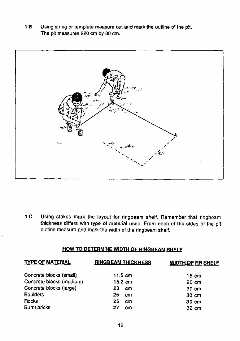
1 B Using string or template measure Out and mark the outline of the pit.The pit measures 220 cm by 80 cm.
1 C Using stakes mark the Iayout for ringbeam shelf. Remember that ringbeamthickness differs with type of material used. From each of the sides of the pitoutline measure and mark the width of the ringbeam shelf.
HOW TO DETERMINE WIDTH OF RINGBEAM SHELF
TYPE OF MATERIAL RINGBEAM THICKNESS WIDTH OF RB SIIELF
Concrete blocks (small)Concrete blocks (medium)Concrete blocks (large)BouldersRocksBurnt bricks
11.5 cm 15 cm15.2 cm 20 cm23 cm 30 cm25 cm 30 cm25 cm 30 cm27 cm 32 cm
12


STEP 2 CASTING SLARS
REMEMBER: that you need three slabs for any Iatrine unless you intend to use a
wooden bench seat. (In that case you would need only two slabs.)
2 A ASSEMBLE WOODEN SLAB CASTING FRAME as follows:
* Cut long pieces of purlin (5cm x 7.5cm)
* Make a wooden frame by nailing together 4 pieces of purlin so that
inner dimensions of wooden frame are 120cm x 85cm x 5cm. Use10cm nails, two on each side.
* Cut 2 pieces of purlin 130cm long. Cut notches on 160cm & 130cm
timber members so that when the frame is assembled, the slabcasting portion would measure 120cm x 85cm. The depth of thenotches on each member should be 2.5 cm.
-r 5 CM _,—‘
15CM
5cM
l3Ocr.i
100CM
(ii_~~L —w L -o ~5CM85cM
7.5CM 7.5CM
13


2 B LEVEL GROUND AND COVER WITH SAND, PLASTIC, PAPER OR FLAT IRONSHEET. PLACE FRAME ON IT.
2 C CUT PIECES OF 6mm STEEL BARS TO THEREINFORCING EACH SLAB.
2 D MIX MORTAR
118cm
83cm
FOLLOWING DIMENSIONS FOR
8 pieces
6 pieces
2 E GAST SLABS AS FOLLOWS
REMEM~ER:
* first slab has no hole
* second stab has small vent-pipe hole
* third slab has one oval seat hole
MIX PROPORTIONS FOR SLAB CASTING MORTAR
1 part cement : 2 1/2 paris rough sand
or
1 bucket cement : 2 1/2 buckets rough sand
Add enough water for the mortar to be workable ( neither too wet nor too dry)
MAKE SURE THAT CEMENT AND SAND ARE THOROUGHLY MIXED BEFOREADDING WATER. THIS WILL MAKE A UNIFORM MIX.
14


i. Place a template mould for the seat slab or a vent pipe ring for the vent-pipe
hole in the appropriate place within the wooden frame.
ii. Lay mortar in the frame to a depth of about 2cm and compact well.
iii. Place steel bars on the layer of mortar.Make sure that the bars do not touch any side of the wooden frame(allowance should be at least 1 cm).1f any bars overlap holes, trim accordingly.
iv. Tie the steel handles to the bars with wire ( only for cover and vent pipeslabs).
v. Place wood inserts in seat slab to enable installation of seat cover.
vi. Cover steel bars with mortar to level with frame.
vii. Make the slab surfaces smooth.
2 F ALLOW THE SLAB TO GURE. THIS IS VERY IMPORTANT.
* Cover with wet paper or wet sand or wet Hessian sack after one
day. (On hot summer days, place wet cover two hours after castingto prevent cracking of surface.
15


* Remove wooden frame after one day but allow slab to stay on the
ground for at least 7 days.
* Sprinkle with water two or three times each day for at least 7 days.
2 G TEST VENT PIPE AND COVER SLABS FOR STRENGTH AFTER 14 DAYS.
* Place slab on 4 pieces of bricks (or wood) at the corners.
* Allow 4 men to stand on the slab.
* Check that the slab is not broken.
~1
‘
16


STEP 3 PIT EXCAVATION AND RINGBEAM CONSTRUCTION
3A DIGTHEMAINPIT
Slope the walls of the pit slightly if a pit lining is not to be constructed, (unstablesoils need gentler slopes).
* Starting from the centre of the outline proceed outwards and deepen the
pit to a depth of about one (1) metre.
3 B DIG THE FOUNDATION SHELF FOR THE RINGBEAM TO A DEPTH BETWEEN15-30cm.
BE SURE THAT THE BASE OFTHEFOUNDATION SHELF IS LEVEL ANDSIDES VERTICAL.
17


3 C CONSTRUCT THE RINGBEAM AS FOLLOWS
* Spread layer of mortar 1 cm thick on shelf. Place first course of Stones on this
layer and cover spaces between stones with mortar.
* Lay stones with mortar
* Continue Iaying stones with mortar until level of stacked stones is at least
20cm above ground.
* With mortar and small stones level the surface of ringbeam.
3 D DEEPEN THE PIT TO A DEPTH OF 2.0 METRES AT LEAST (1F POSSIBLE).
‘~
- -.~, -
- - --.H~’~i’,_,.~
• - _t,-~-’ -
- t:-- ~ •“-———- .:‘ - - -.
18

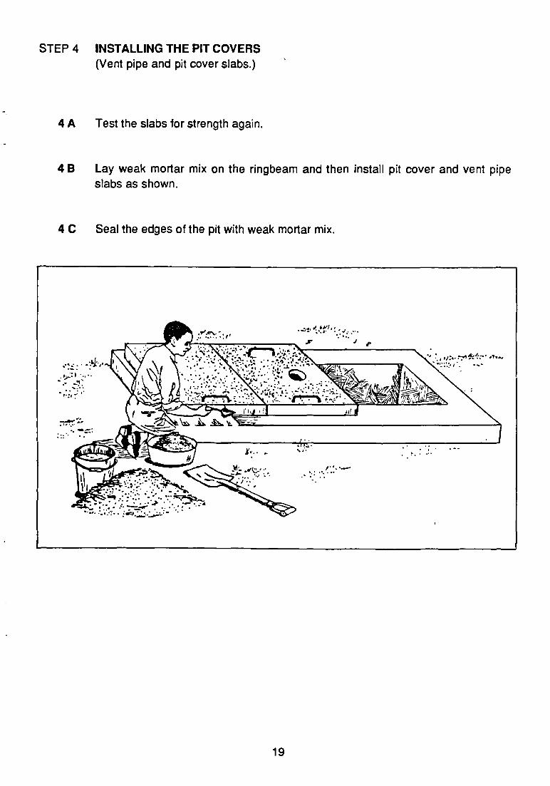
STEP 4 INSTALLING THE PIT COVERS(Vent pipe and pit cover slabs.)
4 A Test the slabs for strength again.
4 B Lay weak mortar mix on the ringbeam and then install pit cover and vent pipeslabs as shown.
4 C Seal the edges of the pit with weak mortar mix.
1
t-:’ —
-.-.,-~.
19


STEP 5 SUPERSTRUCTURE CONSTRUCTION
Internal dimensions of latrine
Length
Width
Height
superstructure
— 120cm
— 80cm
— 200 cm at front— 180 cm at rear
Longitudinal cross section of latrine
20


5A ASSEMBLE DOOR FRAME AND PLACE IN THE ENTRANCE OF THESUPERSTRUCTURE.
* Ensure that it is straight and vertically plumb.
5 B LAY STONES WITH MORTAR UP TO ABOUT 35 cm HIGH
* Ensure that zinc anchors are mortared between the stones to fix them firmly
thus stabilising the frame.
5 C ERECT 10cm TH lOK WALL FROM FLOOR TO FLUSH WITH PROPOSED FRONT
BOTTOM EDGE OF SEAT SLAB.
5 D INSTALL SEAT SLAB INTO SUPERSTRUCTURE WALL
21


5 E CONTINUE LAYING STONES FOR SUPERSTRUCTURE WALLS.
When rear wall reaches height of about 160cm, insert pieces of wire (4 mmdiameter) into this wall and instali rear rafter. Secure rafter with wires.
5 F CONSTRUCT ROOF AND INSTALL DOOR.
5 G TIE FLY-SCREEN ON VENT-PIPE AND INSTALL VENT PIPE IN HOLE ASFOLLOWS:
* Check whether vent-pipe hole is dear
• CAREFULLY drive a 15 cm nail into vent pipe about 15 cm from the
bottom end.
* Place vent pipe firmly in hole.
22


* Ensure that the vent-pipe:
— is truly vertical
— extends above superstructure by at least 50 cm
— fits snugly over hole in the rear slab.
* Fasten securely with wire to the rear rafter at the back of the roof.
* SeaI vent-pipe hole edges with cement.
5 H HAND OVER V.I.P. LATRINE AND ADVISE OWNER ON ITS MAINTENANCEAND USE (SEE PART 2).
23


CONSTRUCTING A DOUBLE PIT (V.I.D.P) LATRINE
1. Select site in consultation with householder
2. Mark Iayout and dig the pit to a depth of between one and two metres.
Note: These are internal dimensions. So it is necessary to dig a slightly bigger pit.The actual size will be determined by the materials to be used for theringbeam.
3. Gast three slabs (2 cover slabs and one seat slab)
• Remember that the seat slab has 2 seat holes.
-~~ r~~ç~—: ~.
75CM 6Ûc’(~
— 735cu~.i
100 CM
IZOCM 4’
VIDP LATRINE SEAT SLAB(Measurements in centimetres)
24


* Remember also that each of the two cover slabs has a vent-pipe hofe.
VIDP COVER SLABS(Measurements in cm)
4. Line the pit wails from top to bottomPit dividing wall and pit lining should be constructed at the same time so that theycould bond properly. Dividing wall must be well sealed with cement plaster to ensurethat It is watertight. Allow the pit lining to project at least 20 cm above ground level. Pitdividing wall should be 15 to 23 cm thick.
25

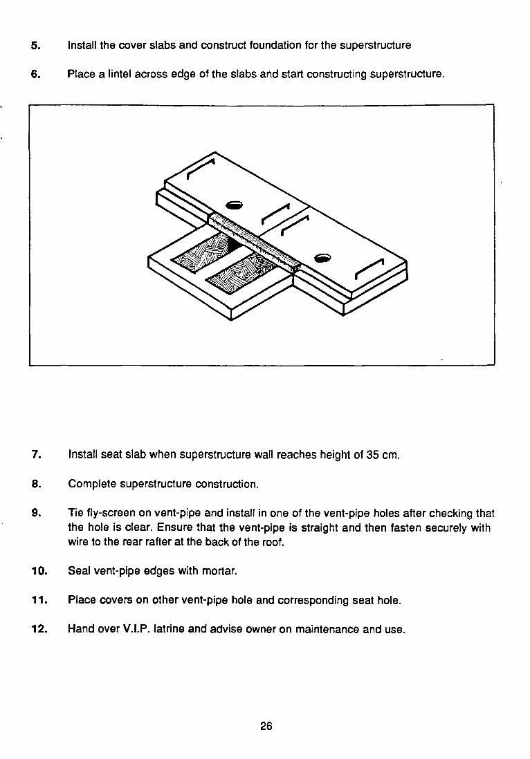
5. Install the cover slabs and construct foundation for the superstructure
6. Place a lintel across edge of the slabs and start constructing superstructure.
7. Install seat slab when superstructure wall reaches height of 35 cm.
8. Complete superstructure construction.
9. Tie fly-screen on vent-pipe and instail in one of the vent-pipe holes after checking thatthe hole is dear. Ensure that the vent-pipe is straight and then tasten securely withwire to the rear rafter at the back of the roof.
10. Seal vent-pipe edges with mortar.
11. Place covers on other vent-pipe hole and corresponding seat hole.
12. Hand over V.I.P. latrine and advise owner ori maintenance and use.
26


F0


PART 2
ADVICE ON THE MAINTENANCE AND USE OF V.I.P. LATRINES
Do remind the latrine owner and the householders about the need for the propermaintenance and use of the V.I.P. latrine.
28


1. PROPER CARE OF A V.I.P. LATRINE.
In order to maintaln the V.I.P. Iatrlne In good condition at all times thelatrine owner should endeavour to undertake the followlng:
a. Check the vent pipe regularly toensure that it is still straight.
c. Keep the latrine seat and floorclean at all times.
b. Check the fly-screen regularly andreplace it if tom or damaged.
d. Keep the latrine door shut at alltimes.
29


e. Keep the interior and exterior of the latrine clean at all times.
30


2. RECOMMENDED HEALTHY PRACTICES
In order to minlmlse the occurrence of dlarrhoeal dlseases withln thefamlly or household, the followlng should also be undertaken:
a. Children’s taeces should bedisposed of immediately in a V.I.P.Iatrine.
c. Every member of the family shouldwash his/her hands after each visitto the latrine.
b. Every member of the tam ilyincluding children should use theV.I.P. latrine.
d. Water for domestic use should becollected and stored in cleancovered containers.
31


e. Water collected from unprotected sources should be boiled first before used fordtinking. You may wish to get together with other community members to protect thecommunity’s source of water.
t. Food shoutd always be covered to protect It from dust and files. Everyone shouldwash their hands before handling lood.
32


PART 3 (ANNEXES)
DETAILS OF THE FOLLOWING:
1 Constructing mortar on burlap shelters
2 Constructing zinc shelters
3 Constructing other pit covers
4 Constructing Timber framework for zinc or mortar on burlap shelters.
33


90CM
ANNEX 1
CONSTRUCTING MORTAR ON BURLAP SHELTERS
Construct timber tramework and fix roof.
2 Construct wooden seat using shelving boards to the tollowing dimensions:
Iength — 90 cmwidth — 60 cmheight — 40 cmthickness — 2.5 cm
* cut Out oval drophole as shown
/ )~9ct.i )~~:cM 1Y60c~
t - -1’
3. Instali the wooden bench seat
* nail the seat boards to the lower studdings of the framework at a height of 40 cm
from the latrine floor:
* support the seat from the underside using joists.
* cover the front portion using other timber boards . Make sure there are nocracks or holes.
34


cover the two sides and the back of the timber tramework with chicken wiremesh.
* soak burlap in cement and salt solution for about 30 minutes, stirringconti nuously.
5. Wrap burlap all around the wire mesh. Fix loose paris of the burlap by tying them to thewire frame.
6. AlIow to dry for at least 2 hours.
7. Using a brush, cover burlap with mortar and allow to dry.
8. Spray on succeeding Iayers of coating using a rough casting machine until thickness is
about 1 cm throughout.
9. Install door.
10 Tie fly-screen on vent-pipe and install in vent-pipe hole.
solution
1 bag cement6 kg salt
72 litres of hot water (8 buckets)
mortar mlxture
2 paris cement3partssand
35


ANNEX 2
ZINC SHELTERS
1. Construct timber framework (same as for burlap on mortar)
2. Construct wooden seat using shelving boards to the following dimensions:
length — 90 cmwidth — 60 cmheight — 40 cmthickness — 2.5 cm
* cut Out oval dropho~eas shown on page 34.
3. Instail the wooden bench seat
* nail the seat boards to the lower studdings of the framework at a height of 40 cm
trom the Iatnne floor:
• support the seat from the underside using joists.
* cover the front portion using other timber boards . Make sure there are nocracks or holes.
4. Cover frame using zinc sheets.
5. Fix roof and instali door.
6. Tie tly-screen on vent-pipe and install, ensuring that vent-pipe remains straight, in hole.
36


ANNEX 3
CONSTRUCTING OTHER PIT COVERS
Householders are generally advised not to dig the pit until it has been properly laid out tosuit the available slabs, but in the event that the householder has already dug a pit which istoo big to fit the standard sized slabs, proceed as follows:
1 Dig a channel on one side of the pit.
2 Construct ring beam around channel to fit standard seat slab.
3 Place lintel across end of channel to support the back wall.
4 Cover main pit with treated poles. Poles should overlap edges of pit by at least 25cmon each side and should be about 40 cm apart.
5 Cover the main poles with the corrugated sheets. Make sure you have cut a hole for
the vent-pipe.
6 lie on flyscreen and position vent-pipe in hole. Seal the edges with mortar.
7 Cover sheets with solI. Spread soli carefully to form mound with sloping sides toensure good drainage.
37


ANNEX 4
TIMBER FRAMEWORK FOR ZINC OR MORTAR ON BURLAP SHELTERS.
Dimensions of labelled tirnber parts
Label No. Dimensions (cm) No. of pieces
123456
5 x 7.5 x5 x 7.5 x5 x 7.5 x5 x 7.5 x5 x 7.5 x5 x 7.5 x
12014080
125180200
222422
A
38


JOINT A
a. Cut notches 7.5 cm wide by 2.5 cm asindicated. Remember to slant the notches asper inclination of the roof.
b. Nail the planks together as shown.
JOINT B
a. Cut 2 cm deep groove on the 5 cm side of thepost.
b. Nail the planks as shown. The plank on theother side of the posts (Z) will be nailed directlywithout cutting any notch on that side.
JOINT C
a. Out a 2 cm deep groove on the 5 cm side of theposts.
b. lnsert stud and nail together
JOINT Da. Cut a notch on the post. It should be 2 cm deep
from the bottom of the post on the 5 cm side.
b. Insert stud into notch and nail it.
c. Nail the other stud directly on the face of thepost.
NRSP1988
z
v
39