
Chapter1 - Introduction to Embedded C Programming With PIC18

A Tutorial Guide to Programming PIC18, PIC24and ATmega Microcontrollers with FlashForth.
2016 Revision
Mechanical Engineering Report 2016/01P. A. Jacobs
School of Mechanical and Mining EngineeringThe University of Queensland.
January 27, 2016
Abstract
Modern microcontrollers provide an amazingly diverse selection of hardware peripherals,all within a single chip. One needs to provide a small amount of supporting hardwareto power the chip and connect its peripheral devices to the signals of interest and, whenpowered up, these devices need to be configured and monitored by a suitable firmwareprogram. These notes focus on programming the 28-pin PIC18F26K22 microcontrollerand its 40-pin PIC18F46K22 sibling in a simple hardware environment. A number ofexample programs, in the Forth language, are provided to illustrate the use of some ofeach microcontroller’s peripheral devices. The examples cover the very simple “flash aLED” exercise through to driving a character-based LCD via its 4-bit parallel interface.The set-up and use of FlashForth 5 on the PIC24FV32KA302 and AVR ATmega328Pmicrocontrollers is also covered.
1

CONTENTS 2
Contents
1 A selection of microcontrollers 4
2 Development boards 72.1 PIC18 family boards . . . . . . . . . . . . . . . . . . . . . . . . . . . . . . 72.2 AVR and PIC24 boards . . . . . . . . . . . . . . . . . . . . . . . . . . . . 10
3 FlashForth 143.1 Getting FlashForth and programming the MCU . . . . . . . . . . . . . . . 143.2 Building for the PIC18F26K22 or PIC18F46K22 . . . . . . . . . . . . . . . 153.3 Building for the PIC24FV32KA302 . . . . . . . . . . . . . . . . . . . . . . 173.4 Building for the ATmega328P . . . . . . . . . . . . . . . . . . . . . . . . . 17
4 Interacting with FlashForth 18
5 Introductory examples 205.1 Hello, World: Flash a LED on the PIC18FX6K22 . . . . . . . . . . . . . . 205.2 Flash a LED on the PIC24FV32KA302 . . . . . . . . . . . . . . . . . . . . 215.3 Flash a LED on the ATmega328P . . . . . . . . . . . . . . . . . . . . . . . 225.4 Set the cycle duration with a variable (PIC18FX6K22) . . . . . . . . . . . 235.5 Hello, World: Morse code . . . . . . . . . . . . . . . . . . . . . . . . . . . 24
6 Read and report an analog voltage 256.1 PIC18FX6K22 . . . . . . . . . . . . . . . . . . . . . . . . . . . . . . . . . . 256.2 PIC24FV32KA30X . . . . . . . . . . . . . . . . . . . . . . . . . . . . . . . 26
7 Counting button presses 28
8 Counting button presses via interrupts 30
9 Scanning a 4x3 matrix keypad 32
10 Base words for an I2C master 3410.1 PIC18FX6K22 . . . . . . . . . . . . . . . . . . . . . . . . . . . . . . . . . . 3410.2 PIC24FV32KA30X . . . . . . . . . . . . . . . . . . . . . . . . . . . . . . . 3610.3 ATmega328P . . . . . . . . . . . . . . . . . . . . . . . . . . . . . . . . . . 3810.4 Notes on using the words . . . . . . . . . . . . . . . . . . . . . . . . . . . . 4010.5 Detecting I2C devices . . . . . . . . . . . . . . . . . . . . . . . . . . . . . . 41
11 Using I2C to get temperature measurements 42
12 Making high-resolution voltage measurements 43
13 An I2C slave example 45

CONTENTS 3
14 Speed of operation – bit banging 4914.1 PIC18F26K22 . . . . . . . . . . . . . . . . . . . . . . . . . . . . . . . . . . 4914.2 PIC24FV32KA302 . . . . . . . . . . . . . . . . . . . . . . . . . . . . . . . 5114.3 ATmega328P . . . . . . . . . . . . . . . . . . . . . . . . . . . . . . . . . . 53
15 Driving an Hitachi-44780 LCD controller 56
A Using other terminal programs on Linux 60

1 A SELECTION OF MICROCONTROLLERS 4
1 A selection of microcontrollers
Over the past couple of decades, microcontrollers have evolved to be cheap, powerfulcomputing devices that even Mechanical Engineers can use in building bespoke instru-mentation for their research laboratories. Typical tasks include monitoring of analogsignals, sensing pulses and providing timing signals. Of course these things could be donewith a modern personal computer connected via USB to a commercial data acquisitionand signal processing system but there are many situations where the small, dedicatedmicrocontroller, requiring just a few milliamps of current, performs the task admirablyand at low cost.
Modern microcontrollers provide an amazingly diverse selection of hardware peripherals,all within a single chip. One needs to provide a small amount of supporting hardwareto power the chip and connect its peripheral devices to the signals of interest and, whenpowered up, these devices need to be configured and monitored by a suitable firmwareprogram. These following sections provide an introduction to the details of doing this withan 8-bit Microchip PIC18F26K22 or PIC18F46K22 microcontroller, a 16-bit MicrochipPIC24FV32KA302 microcontroller and an 8-bit Atmel ATmega328P microcontroller, allprogrammed with the FlashForth version 5 interpreter [1].
Within each family of Microchip or Atmel microcontrollers, the individual microcontrollerunits (MCUs) all have the same core, i.e. same instruction set and memory organisation.Your selection of which MCU to actually use in your project can be based on a coupleof considerations. If you are on a tight budget and will be making many units, choosean MCU with just enough functionality, however, if convenience of development is moreimportant, choose one with “bells and whistles”. For this tutorial guide, we will valueconvenience and so will work with microcontrollers that have:
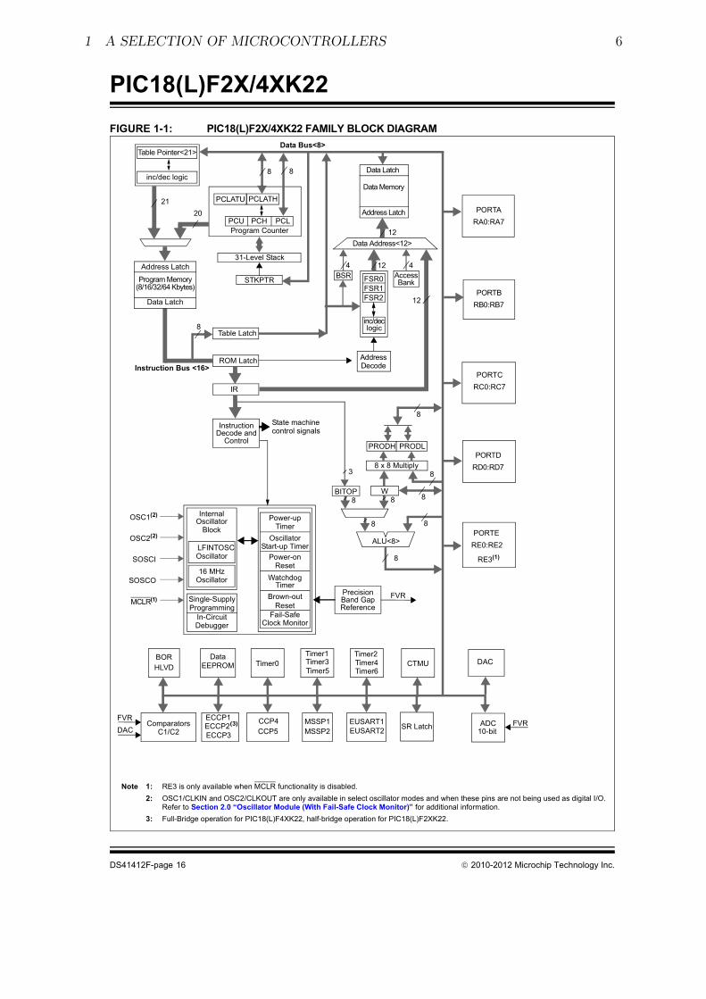
• a nice selection of features, including a serial port, several timers and an analog-to-digital converter. See the feature list and the block diagram of the PIC18F26K22and PIC18F46K22 MCUs on the following pages.
• a 28-pin narrow or 40-pin DIL package, which is convenient for prototyping and hasenough I/O pins to play without needing very careful planning.
• an ability to work as 3.3V or 5V systems.
• a pinout as shown at the start of the datasheets (books) [2, 3, 4]. You will be readingthe pages of these books over and over but we include the following couple of pagesfrom the PIC18F22K26/PIC18F46K22 datasheet to give an overview.
• an internal arrangement that is built around an 8-bit or 16-bit data bus.
• the “Harvard architecture” with separate paths and storage areas for program in-structions and data.
We won’t worry too much about the details of the general-purpose registers, the internalstatic RAM or the machine instruction set because we will let the FlashForth interpreterhandle most of the details, however, memory layout, especially the I/O memory layoutis important for us as programmers. The peripheral devices, which are used to inferfacewith the real world, are controlled and accessed via registers in the data-memory space.

1 A SELECTION OF MICROCONTROLLERS 5
����������� �������� ������������ ���������������
���������� ��
��������������������� ���
� ��������������� �!�"�������#�$
� ���������%���!�!���&�#�����&���!�&����!��
����� ���������� �!�
� '���������(���&������))*+��
� '��� ,� -.���& /�����*��������
"!!�&&���
� '�����01,�(���&�/���������������"!!�&&�
���
� '�����,���*���������
� �,�.���2�!����&�#����&3�0�.���2�!�������*���
� *�����/�4��&�5�����#��&
� ���/�4��3��5�6���"���&&�.���7�!6�������8
� 0�%�0��������������7�!6����#�������
!�"�#!��$%��!!�&����&�'�&'��
� *���&����, �7 ����������&������ (��8$
� ����������.���!���9��:
� �������.���5�;#�����&3��� 87 ����, �7
� ,� �7 ���5�������4����.���#&����*//�<
���%�������������&��;#��!
� �#���&�����!�&�#����,� �7
� 6�)%���������8��!�&�#����,� �7
� �=�*��&��/�8�/��>*//?
� ����!����&�������#&���� �����@��� 87
� �������5�����8�����$
� "��6&�5�&�5��&�#�!6���5�������������8�
&��&
� 6�����!��&������������#�
(��!�����&'��%
� "�����������������4����>"��?��!#��$�
� ���.����&�#���3�#��������%����� �������&
� "#����;#�&���������.�����
� ��4�&����4����.���!#���������
� ��%�!�A������+�5������>�A+?��������
� ��!����!�������#���#������%���
� "�������������!#��$
� 6�����������������������&
� ��!����!�������#���#������%���
� ����������"�������4����>�"�?��!#��$
� ��%�!�A������+�5������>�A+?�6���������A3
����0A���!����1,A�#��#����4��&
� B�.��������������&�&��4���"��6�����&���4�
��!�������4� �5������&�������
� ����� ��� ���&#������'����>� �'?��!#��$
� �#���&���������4���#���&��&����5��#���
&����&���!���������4��&6�����&
)"&�������*���*���+��������&
���������� ���*�&� ���
� �������!�$�����"3��������
� 2����!�� ���$ �����"3��������
� ������&������$�0����"�@����87
� *���������!#�����&�.��
�,����!�+�������&��!!�����&'��%
� ���A���B�BA���������<�*���0�==-���!�4���&
� ��0A�����,A���������<�*���0/�==-���!�4���&
� ���5�*�����.���#�!���5�6�������
� 7���C/6�A���������������>7/A�?��!#��$
� *�����.����,�/�4��
� ����#�����7���C/6�A��������������
� *�����.���(6��#��+�&���>(�+?$
� 2����&5�6������.�������
� ��5��#�.���&�#�!6����������
� )%���!�!�2����!�� ����>2� ?$
� *�����.������!�5� � �&������&
� �������#���������*�������D�>���*D?$
� ��������#������A
� ������#�����.#��>���?
����,����!�����!���&%
� '�����B��C��*��&���#&������#�������*��$
� 7�����#�������8C�#����B �"C�B �"
� ����������.����%����������#��&
� �#�������.�������#�����������
� E����������.���6��8��#���#�&
� *�����.���&��6 ���
� �+�/����$
� �#����������C+�&������#������&
� 6�����#�C�����C*2��>��*?��!#��&
� ����)������!���*�>)��*?��!#��&$
� ���3��6��5#�*2��#��#�&
� �������.���������
� *�����.���!��!�����
� "#����#�!6����!�"#��+�&���
� *2��&������
� 6���&���������#&�������*��>���*?�
�!#��&$
� ��6����*��>&#���&��������!�&?
� ���D���&�����!����4���!�&�6�����!!�&&
��&8
������������� ��� ������������� ���������� � �� ������������������� � ��
1 A SELECTION OF MICROCONTROLLERS 6
���������� ��
������������� ������������������������������������
����� ���� ���������� �������� ������������� ��
���������������������������
��� ���
�����!���
"������� ���
���"������#��$
��
"�����%�& ��&�
��&�
��&�
���'�������
"������
� �� �
(�)����(�
�����(� "�)
*
+�� �,������-
(���!��������
(&.� (&.�)
*�/�*���������
*
%��.(**
" 0#*$
��
*
*
�1���(������#��$
���'��������
��
*
�������� �!
�1��� ���*
��&
��
+
&.�� ���
(� "�0
(�0
"#�$ �� &2+���������,��1���3������ &�4������������������1����
� .���'� 5�6��� .���'� 5.0� ��������,��1����� �����������������!������� 3��������� ���� �������1������������������'.�&�4������%$&�'#( )*�+��&',,��#-��#.�,$��/'�0��',�%�1$��,#&2��#('�#-�3�4��������������4��!�����
4� �����%��������������4���(���*7 8��95��:���4�1��������������4���(���*7 8��95���
20�"&����!������ ���(�
���1��"��
��!�����!���
���0��!���
��(�
) ;�
2��(�
%.& ��
22(&.�
<
�(��-�&�'#(����� �5!
��5(�& %�-
*
�����!������������������
������
*
*(�3�������!��
.������������������!��
(�3�����&����
<�������!��
.�����
.�����
%��3�����
&����
�������.��������
�����4�����-��������
(��������
&�4������%���=��� &���
%���-
��6�.��.��������
� ��)>.��������
������������(���!!��
������������1���
�.��.
�.���
�;&
�;&�;&
�"�
"������� ���
(���!���!���7*'� '+�' �51����8
��� ���
(.&�"
&"�?&"@
(.&�%
&%�?&%@
(.&��
&��?&�@
(.&��
&��?&�@
��!�����!��
��!��+
��!��A
�&� ���20�"&�����(���(A
2��(��4���'�� 2��(+
(.&�2
&2�?&2�
&2+���
�"�
2 DEVELOPMENT BOARDS 7
2 Development boards
This tutorial is based around simple support hardware for each of the microcontrollers.If you don’t want to do your own soldering, there are easy-to-buy demonstration boardsavailable as a convenient way to get your hardware up and going. If you are a student ofmechatroncis, however, you must eventually design and build your own hardware. Thestrip-board versions are aimed at you.
2.1 PIC18 family boards
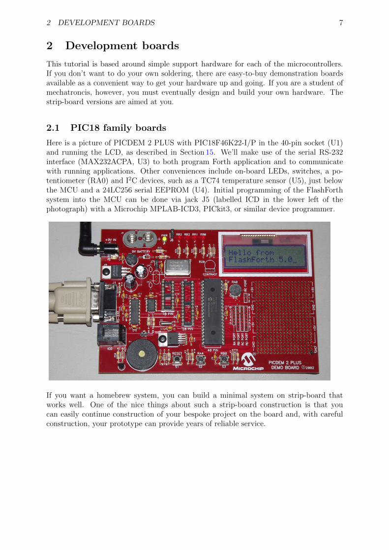
Here is a picture of PICDEM 2 PLUS with PIC18F46K22-I/P in the 40-pin socket (U1)and running the LCD, as described in Section 15. We’ll make use of the serial RS-232interface (MAX232ACPA, U3) to both program Forth application and to communicatewith running applications. Other conveniences include on-board LEDs, switches, a po-tentiometer (RA0) and I2C devices, such as a TC74 temperature sensor (U5), just belowthe MCU and a 24LC256 serial EEPROM (U4). Initial programming of the FlashForthsystem into the MCU can be done via jack J5 (labelled ICD in the lower left of thephotograph) with a Microchip MPLAB-ICD3, PICkit3, or similar device programmer.
If you want a homebrew system, you can build a minimal system on strip-board thatworks well. One of the nice things about such a strip-board construction is that youcan easily continue construction of your bespoke project on the board and, with carefulconstruction, your prototype can provide years of reliable service.

2 DEVELOPMENT BOARDS 8
Here is a detailed view of the home-made demo board with PIC18F26K22 in place. Thisboard is suitable for the exercises in this guide. A separate regulator board is to theleft and a current-limited supply provides the input power. The board is simple to makeby hand, with header pins for the reset switch and connections to the LEDs. The 4-pinheader in the foreground provides an I2C connection. The ICSP header is only needed toprogram FlashForth into the MCU, initially. All communication with the host PC is thenvia the TTL-level serial header (labelled FTDI-232) at the right. Beyond the minimumrequired to get the microcontroller to function, we have current-limiting resistors andheader pins on most of the MCU’s I/O pins. This arrangement is convenient for exercisessuch as interfacing to the 4x3 matrix keypad (Section 9).
The schematic diagram of this home-brew board is shown on the following page. Note thatthere is no crystal oscillator on the board; the internal oscillator is sufficiently accurate forasynchronous serial port communication. Note, also, the 1k resistors in the TX and RXnets. These limit the current going through the microcontroller pin-protection diodes inthe situation where the microcontroller board is unpowered and the FTDI-232 cable is stillplugged in to your PC. This will happen at some point and, without the current-limitingresistors, the FTDI cable will power the microcontroller, probably poorly.

2 DEVELOPMENT BOARDS 9
FIL
E:
RE
VIS
ION
:
DR
AW
N B
Y:
PA
GE
OF
TIT
LE
2 4 61 3 5
CO
NN
_IC
SP
+5V
Vss
!MC
LR
VD
D
VS
S
DA
TA
CLK
NC
1N4004
1k
1k
pic
18f2
6k22 n
ot−
quite m
inim
al dem
o b
oard
Pete
r Jacobs
100n
470
Vss
11
+5
V
Vss
Vss
470
470
RB
1
RB
0
21
CO
NN
_R
ES
ET
32 41
CO
NN
_I2
C
5k6
5k6
Vss
+5
V
10
Vss
SD
A
SC
L
+V
GN
D
GN
D
HO
ST
_T
X
HO
ST
_R
X
330
330
330
330
330
330
330
330
330
RB
5
RB
4
RB
3
RB
2
RA
1
RA
0
RA
2
RA
3
RA
4
RA
5
RC
0
RC
1
RC
2
330
330
330
330
330
330
30−
Apr−
2014
330
MC
U_R
X
SD
AS
CL
PIC
18F
26K
22
!MC
LR
/VP
P/R
E3
1
RA
0/A
N0
2
RA
1/A
N1
3
RA
2/A
N2
4
RA
3/A
N3
5
RA
46
RA
5/A
N4
7
VS
S8
OS
C1/R
A7
9
OS
C2/R
A6
10
RC
01
1
RC
11
2
RC
21
3
RC
3/S
CL
14
RC
4/S
DA
15
RC
51
6
RC
6/T
X1
7
RC
7/R
X1
8
VS
S1
9
VD
D2
0
RB
02
1
RB
12
2
RB
22
3
RB
32
4
RB
42
5
RB
52
6
RB
6/P
GC
27
RB
7/P
GD
28
U?
SD
A
SC
L
MC
U_R
X MC
U_T
X
2 4 61 3 5
FT
DI−
232
RC
5
MC
U_T
X
NC
NC
NC
330
RA
7
330
RA
6
RB
6/P
GC
RB
7/P
GD
RB
6/P
GC
RB
7/P
GD
21
CO
NN
_P
OW
ER
Vss
+5
V
1 2
2u2

2 DEVELOPMENT BOARDS 10
2.2 AVR and PIC24 boards
The Eleven from Freetronics, shown in the left half of the following photograph, is anArduino-compatible board carrying an ATmega328P microcontroller. This is a conve-nient piece of hardware with many prototype-friendly boards available to plug into theheaders around the periphery of the board. Although these boards come with the Arduinobootloader preprogrammed into the ATmega328 microcontroller, the standard AVR 6-pinprogramming header on the right-hand end of the board (in the photo) can be used toreprogram the microcontroller with the FlashForth interpreter. Power and serial portaccess is through the USB connector at the left.
If you want an almost-no-solder option for prototyping with the PIC24FV32KA302, Mi-crochip provide the Microstick 5V for PIC24K-series. As shown in the following photo-graph, this is convenient in that it includes a programmer on-board and can be pluggedinto a bread-board. The power supply and flash programming access is provided throughthe USB connector on the left of the board while the serial port connection is via the6-pin connector on the right-end of the board.

2 DEVELOPMENT BOARDS 11
Building a minimal board, by hand, for any of these processors is fairly easy and strip-board versions for each is shown in the following photograph. The left-hand board is forthe PIC18F26K22, before all of the extra protection resistors were added. In this state,FlashForth can already be used on this board for nearly all of the exercises in the followingsections. Schematic diagrams for the PIC24 and AVR microcontrollers are shown on thefollowing pages.
Each of the boards has headers for (1) power, (2) in-circuit serial programming, (3) I2Ccommunication and (4) TTL-level-232 serial communication. The ATmega328 board onthe right has a few more protection resistors installed and has an 16 MHz crystal becauseserial-port communication was found to be unreliable using the internal oscillator.

2 DEVELOPMENT BOARDS 12
FIL
E:
RE
VIS
ION
:
DR
AW
N B
Y:
PA
GE
OF
TIT
LE
2 4 61 3 5
CO
NN
_IC
SP
+5V
1N4004
1k
1k
AV
R A
Tm
ega328 n
ot−
quite m
inim
al dem
o b
oard
Pete
r Jacobs
100n
470
Vss
11
+5V
Vss
Vss
470
470
PD
2
PD
3
21
CO
NN
_R
ES
ET
32 41
CO
NN
_I2
C
5k6
5k6
Vss
+5
V
10
Vss
SD
A
SC
L
+V
GN
D
GN
D
HO
ST
_T
X
HO
ST
_R
X
30−
Apr−
2014
MC
U_R
X
SD
A
SC
L
SD
A
SC
L
MC
U_R
X
MC
U_T
X
2 4 61 3 5
FT
DI−
232
MC
U_T
X
NC
NC
NC
MIS
O
MO
SI
SC
K
MO
SI
21
CO
NN
_P
OW
ER
Vss
+5
V
1 2
2u2
!RE
SE
T
!RE
SE
T
NC
NC
NC
NC
NC
NC
NC
10R
+5
V
Vss
100n
NC
NC
AT
mega328
PC
6 (
!RE
SE
T)
1
PD
0 (
RX
D)
2
PD
1 (
TX
D)
3
PD
24
PD
35
PD
46
VC
C7
GN
D8
PB
6 (
XT
AL1)
9
PB
7 (
XT
AL2)
10
PD
51
1
PD
6 (
AIN
0)
12
PD
7 (
AIN
1)
13
PB
01
4P
B1
15
(!S
S)
PB
21
6
(MO
SI)
PB
31
7
(MIS
O)
PB
41
8
(SC
K)
PB
51
9
AV
CC
20
AR
EF
21
GN
D2
2
PC
02
3
PC
12
4
PC
22
5
PC
32
6
(SD
A)
PC
42
7
(SC
L)
PC
52
8
U1
470
PD
4
Vss
MIS
O
SC
K
100n
NC
U2
16M
Hz
15pF
15pF

2 DEVELOPMENT BOARDS 13
FIL
E:
RE
VIS
ION
:
DR
AW
N B
Y:
PA
GE
OF
TIT
LE
2 4 61 3 5
CO
NN
_IC
SP
+5V
Vss
!MC
LR
VD
D
VS
S
DA
TA
CLK
NC
1N4004
1k
1k
PIC
24F
V32K
A302 n
ot−
quite m
inim
al dem
o b
oard
Pete
r Jacobs
100n
470
Vss
11
+5
V
Vss
Vss
470
470
RB
15
RB
14
21
CO
NN
_R
ES
ET
32 41
CO
NN
_I2
C
5k6
5k6
Vss
+5
V
10
Vss
SD
A
SC
L
+V
GN
D
GN
D
HO
ST
_T
X
HO
ST
_R
X
330
330
25−
Jan−
2016
MC
U_R
X
SD
A
SC
LS
DA
SC
L
MC
U_R
X
MC
U_T
X
2 4 61 3 5
FT
DI−
232
MC
U_T
X
NC
NC
NC
RB
6/P
GC
RB
7/P
GD
RB
6/P
GC
RB
7/P
GD
21
CO
NN
_P
OW
ER
Vss
+5
V
1 2
2u2
!MC
LR
!MC
LR
NC
NC
NC
NC
NC
NC
NC
NC
NC
NC
NC
12
10uF
10R
+5
V
Vss
100n
Vss
NC
NC
10k
+5
V
NC
PIC
24F
V32K
A302
!MC
LR
/RA
51
RA
02
RA
13
RB
0/P
GE
D1
4
RB
1/P
GE
C1
5
RB
2/U
1R
X6
RB
37
VS
S8
RA
2/O
SC
I9
RA
3/O
SC
O1
0
RB
41
1
RA
41
2
VD
D1
3
RB
51
4R
B6
15
RB
7/U
1T
X1
6
RB
8/S
CL1
17
RB
9/S
DA
11
8
RA
71
9
VC
AP
20
RB
10/P
GE
D2
21
RB
11/P
GE
C2
22
RB
12
23
RB
13
24
RB
14
25
RB
15
26
AV
SS
27
AV
DD
28
U1

3 FLASHFORTH 14
3 FlashForth
Forth is a word-based language, in which the data stack is made available to the pro-grammer for temporary storage and the passing of parameters to functions. Everythingis either a number or a word. Numbers are pushed onto the stack and words invoke func-tions. The language is simple enough to parse that full, interactive Forth systems maybe implemented with few (memory) resources. Forth systems may be implemented in afew kilobytes of program memory and a few hundred bytes of data memory such that itis feasible to provide the convenience of a fully interactive program development on verysmall microcontrollers.
The classic beginners book by Brodie [5] is available online1, as is Pelc’s more recentbook [6]2. A more detailed reference is published by Forth Inc [7]. These books are biasedtoward Forth running on a personal computer rather than on a microcontroller, however,they are a good place to start your reading. For an introductory document that is specificto FlashForth, see the companion report [8].
FlashForth [1] for the PIC18, PIC24 and ATmega families of microcontrollers is a fullinterpreter and compiler that runs entirely on the microcontroller. It is a 16-bit Forth witha byte-addressable memory space. Even though there are distinct memory types (RAM,EEPROM and Flash) and separate busses for data and program memory in these Harvard-architecture microcontrollers, FlashForth unifies them into a single 64kB memory.
Above working in assembler, FlashForth does use some resources, both memory andcompute cycles, but it provides such a nice, interactive environment that these costs areusually returned in convenience while tinkering with your hardware. Forth programs arevery compact so you will have less code to maintain in the long run. The interpretercan also be available to the end user of your instrument, possibly for making parameteradjustments or for making the hardware versatile by having a collection of applicationfunctions present simultaneously in the firmware, with the user selecting the requiredfunction as they wish.
3.1 Getting FlashForth and programming the MCU
FlashForth is written in assembler, with one program source for each of the microcontrollerfamilies and a number of Forth text files to augment the core interpreter. The source codecan be downloaded from SourceForge at the URLhttp://sourceforge.net/projects/flashforth/
There, you will see that you can get a packaged release or you can clone the git repository.
To build from this source, you will need to start up your integrated development environ-ment (be it MPLAB, MPLAB-X or AVR Studio), open the program source and configfiles in this IDE and edit the config file(s) match your selection of oscillator. There areother options to customize but the choice of oscillator is the main one. The machinecode can then be assembled and programmed into your microcontroller with a suitabledevice programmer (PICkit3, ICD3, STK500, AVRISP MkII, ...). Once programmed with
1http://home.iae.nl/users/mhx/sf.html and http://www.forth.com/starting-forth/2http://www.mpeforth.com/
3 FLASHFORTH 15
FlashForth, and mounted in a board that provides power and serial communications asdescribed in the previous section, you will be ready to interact with FlashForth via aserial terminal or shell.
3.2 Building for the PIC18F26K22 or PIC18F46K22
For our minimal system with either the PIC18F26K22 or PIC18F46K22 microcontroller,we elect to use the internal (16 MHz) oscillator multiplied by 4 by the PLL. Within theMPLAB-X development environment, we started a new standalone project to build ourFlashForth program that will use the microcontroller’s UART serial port as the OPERA-TOR communications channel. Following the prompt screens, we selected a specific pro-cessor (PIC18F26K22), our hardware tool (ICD3), and the compiler toolchain (mpasm).
To build the actual machine code that will be programmed into the flash memory of the mi-crocontroller, it is sufficient to assemble the principal source file ff-pic18.asm along withthe configuration (or header) files pic18f-main.cfg, pic18fxxxx.cfg, p18f2x4xk22.cfg,and use the linker script FF_0000.lkr. The source file and config files can be found inthe directory pic18/src/, while the linker file is in pic18/lkr/. There may be otherconfiguration files already added to the project but you can ignore them.
We edited the processor-specific config file, p18f2x4xk22.cfg, writing “PLLCFG = ON” tohave the PLL enabled (giving FOSC = 64 MHz), enable the watchdog timer with a 1:256postscale (WDTPS = 256) to get approximately a 1 second time-out period, and enable theexternal reset capability (MCLRE = EXTMCLR). Being able to reset the microcontroller bybringing the MCLR pin low is something that we find convenient when tinkering with newhardware. We set the final line as#define PLL ENABLE
We needed to edit the pic18f-main.cfg file only to set the system clock frequency asconstant clock=d’64000000’. With this clock frequency, the microcontroller requiresapproximately 7 mA current while the interpreter is running and waiting for input.
There are many other options for customizing the FlashForth program in this file, however,the default parameters are fine for the first build of our minimal system. To see youroptions for all of the configuration bits for your specific microcontroller, it is convenientto open the MPLAB-X view from the main menu: Window → PIC Memory Views →Configuration Bits.
With the specific microcontroller selected for the project, the config file pic18fxxxx.cfg
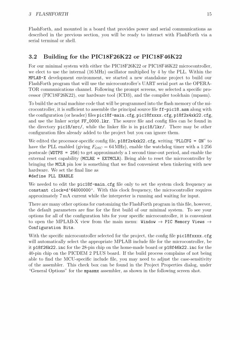
will automatically select the appropriate MPLAB include file for the microcontroller, beit p18f26k22.inc for the 28-pin chip on the home-made board or p18f46k22.inc for the40-pin chip on the PICDEM 2 PLUS board. If the build process complains of not beingable to find the MCU-specific include file, you may need to adjust the case-sensitivityof the assembler. This check box can be found in the Project Properties dialog, under“General Options” for the mpasmx assembler, as shown in the following screen shot.
3 FLASHFORTH 16
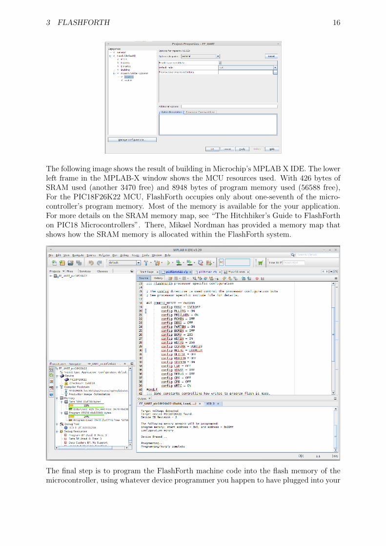
The following image shows the result of building in Microchip’s MPLAB X IDE. The lowerleft frame in the MPLAB-X window shows the MCU resources used. With 426 bytes ofSRAM used (another 3470 free) and 8948 bytes of program memory used (56588 free),For the PIC18F26K22 MCU, FlashForth occupies only about one-seventh of the micro-controller’s program memory. Most of the memory is available for the your application.For more details on the SRAM memory map, see “The Hitchhiker’s Guide to FlashForthon PIC18 Microcontrollers”. There, Mikael Nordman has provided a memory map thatshows how the SRAM memory is allocated within the FlashForth system.
The final step is to program the FlashForth machine code into the flash memory of themicrocontroller, using whatever device programmer you happen to have plugged into your
3 FLASHFORTH 17
development system. The Dashboard view in the screen shot above shows that we haveseleted to use of the MPLAB ICD3.
3.3 Building for the PIC24FV32KA302
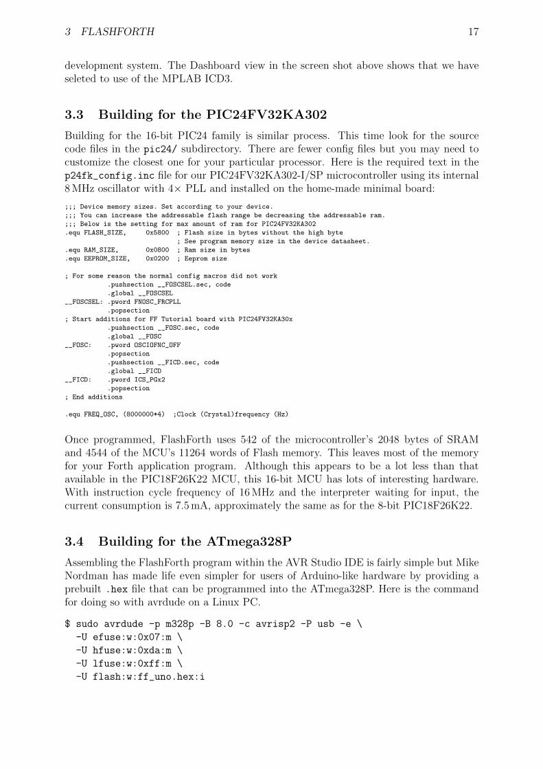
Building for the 16-bit PIC24 family is similar process. This time look for the sourcecode files in the pic24/ subdirectory. There are fewer config files but you may need tocustomize the closest one for your particular processor. Here is the required text in thep24fk_config.inc file for our PIC24FV32KA302-I/SP microcontroller using its internal8 MHz oscillator with 4× PLL and installed on the home-made minimal board:
;;; Device memory sizes. Set according to your device.
;;; You can increase the addressable flash range be decreasing the addressable ram.
;;; Below is the setting for max amount of ram for PIC24FV32KA302
.equ FLASH_SIZE, 0x5800 ; Flash size in bytes without the high byte
; See program memory size in the device datasheet.
.equ RAM_SIZE, 0x0800 ; Ram size in bytes
.equ EEPROM_SIZE, 0x0200 ; Eeprom size
; For some reason the normal config macros did not work
.pushsection __FOSCSEL.sec, code
.global __FOSCSEL
__FOSCSEL: .pword FNOSC_FRCPLL
.popsection
; Start additions for FF Tutorial board with PIC24FV32KA30x
.pushsection __FOSC.sec, code
.global __FOSC
__FOSC: .pword OSCIOFNC_OFF
.popsection
.pushsection __FICD.sec, code
.global __FICD
__FICD: .pword ICS_PGx2
.popsection
; End additions
.equ FREQ_OSC, (8000000*4) ;Clock (Crystal)frequency (Hz)
Once programmed, FlashForth uses 542 of the microcontroller’s 2048 bytes of SRAMand 4544 of the MCU’s 11264 words of Flash memory. This leaves most of the memoryfor your Forth application program. Although this appears to be a lot less than thatavailable in the PIC18F26K22 MCU, this 16-bit MCU has lots of interesting hardware.With instruction cycle frequency of 16 MHz and the interpreter waiting for input, thecurrent consumption is 7.5 mA, approximately the same as for the 8-bit PIC18F26K22.
3.4 Building for the ATmega328P
Assembling the FlashForth program within the AVR Studio IDE is fairly simple but MikeNordman has made life even simpler for users of Arduino-like hardware by providing aprebuilt .hex file that can be programmed into the ATmega328P. Here is the commandfor doing so with avrdude on a Linux PC.
$ sudo avrdude -p m328p -B 8.0 -c avrisp2 -P usb -e \
-U efuse:w:0x07:m \
-U hfuse:w:0xda:m \
-U lfuse:w:0xff:m \
-U flash:w:ff_uno.hex:i

4 INTERACTING WITH FLASHFORTH 18
The fuses are set to use the 16 MHz crystal on the Arduino-like board.
4 Interacting with FlashForth
Principally, interaction with the programmed MCU is via the serial port. For the PIC mi-crocontrollers, settings are 38400 baud 8-bit, no parity, 1 stop bit, with software (Xon/X-off) flow control. For the ATmega328P (as programmed above), the baud rate is 9600.
The FlashForth distribution includes a couple of shell programs that are programmedwith some knowledge of the FlashForth interpreter. The ff-shell.py program is writtenin Python and allows interaction with the microcontroller via a standard command shell.It depends on a Python interpreter and the pyserial extension being installed on your PC.The ff-shell.tcl is a GUI program that displays the interaction text in a dedicatedwindow on your PC. It requires the Tcl/Tk interpreter which is usually part of a Linuxenvironment but it may be installed on MS-Windows or MacOSX as well.
The following images shows the ff-shell.tcl window just afer sending the content ofthe flash-led.txt file to the PIC18F26K22. The device name of /dev/ttyUSB0 on thestatus line refers to the USB-to-serial interface that was plugged one of the PC’s USBports. It is convenient to start the program with the command
$ sudo ./ff-shell.tcl
If necessary, you can adjust the communication settings by typing new values into theentry boxes and pressing Enter to repoen the connection.
As you type characters into the main text widget, ff-shell.tcl intercepts them andsends them, one at a time, via the serial port to the microcontroller. As the microcontrollersends characters back, the program filters them and displays them in the text widget.There is also a send-file capability that will send the text from the file as fast as it can,

4 INTERACTING WITH FLASHFORTH 19
without overwhelming the microcontroller. The Python program ff-shell.py has aspecial command #send to start the equivalent process.
If you have sent the microcontroller off to do a repetitive task, such as flashing the LEDindefinitely, you can regain the interpreter’s attention by sending a Control-O character.The interpreter aborts the execution of the current word and does a software restart.After initialization, the interpreter announces that it is ready to begin. Subsequentlypressing Enter will get the ok response, as shown below. The warm restart action is alsoavailable from the menu as Micro→Warm Restart.
We find ff-shell.tcl a very convenient interaction environment, however, if you wantto use a standard terminal program on Linux, Appendix A provides a few notes for doingso.

5 INTRODUCTORY EXAMPLES 20
5 Introductory examples
We begin with examples that demonstrate a small number of features of the MCU or ofFlashForth. Our interest will primarily be in driving the various peripherals of the MCUrather than doing arithmetic or dealing with abstract data.
5.1 Hello, World: Flash a LED on the PIC18FX6K22
The microcontroller version of the “Hello, World” program is typically a program thatflashes a single LED. It will work on either of PIC18F microcontrollers mentioned pre-viously and makes use of a digital input-output pin via the registers that control the IOport. The datasheet [2] has a very readable introduction to the IO ports. Please read it.
1 -flash -led
2 marker -flash -led
3 $ff8a constant latb
4 $ff93 constant trisb
5 : init 1 trisb mclr ; \ want RB0 as output
6 : do_output latb c@ 1 xor latb c! ; \ toggle RB0
7 : wait #500 ms ;
8 : main init begin do_output wait again ;
9 main
Notes on this program:
• If the word -flash-led has been previously defined with the word marker, line 1resets the dictionary state and continues interpreting the file, else the interpretersignals that it can’t find the word and continues interpreting the file anyway.
• Line 2 records the state of the dictionary and defines the word -flash-led so thatwe can reset the dictionary to its state before the code was compiled, simply byexecuting the word -flash-led.
• Lines 3 and 4 define convenient names for the addresses of the file registers thatcontrol IO-port B. Note the literal hexadecimal notation with the $ character. Inthe PIC18F family, the special function registers for interacting with the MCUhardware appear near the top of the 64k FlashForth memory space.
• Line 5 is a colon definition for the word init that sets up the peripheral hardware.Here, we set pin RB0 as output. The actual command that does the setting ismclr, which takes a bit-mask (00000001) and a register address ($ff93) and thenclears the register’s bits that have been set in the mask. Note the comment startingwith the backslash character. Although the comment text is sent to the MCU, it isignored. Note, also, the spaces delimiting words. That spaces after the colon andaround the semicolon are important.
• Line 6 is the definition that does the work of fiddling the LED pin. We fetch thebyte from the port B latch, toggle bit 0 and store the resulting byte back into theport B latch.
5 INTRODUCTORY EXAMPLES 21
• Line 7 defines a word to pause for 500 milliseconds. Note the # character for a literaldecimal integer.
• Line 8 defines the “top-level” coordination word, which we have named main, fol-lowing the C-programming convention. After initializing the relevant hardware, itunconditionally loops, doing the output operation and waiting, each pass.
• Line 9 invokes the main word and runs the application. Pressing the Reset buttonwill trigger a hardware restart, kill the application and put the MCU back into astate of listening to the serial port. Invoking a warm restart by typing Control-O
or selecting the Warm Restart menu action in ff-shell.tcl may be a more conve-nient way to stop the application. Typing main, followed by Enter will restart theapplication.
Instead of going to the bother of tinkering with the MCU IO Port, we could have takena short-cut and used the string writing capability of Forth to write a short version thatwas closer the the operation of typical Hello World programs.
1 : greet -me ." Hello World" ;
2 greet -me
Before going on to more examples, it is good to know about the word empty. This wordwill reset the dictionary and all of the allotted-memory pointers. Because FlashForth doesnot allow you to redefine words that are already in the dictionary, later examples thatuse the same names for their word definitions, may not compile without complaint if youdon’t clean up after each exercise.
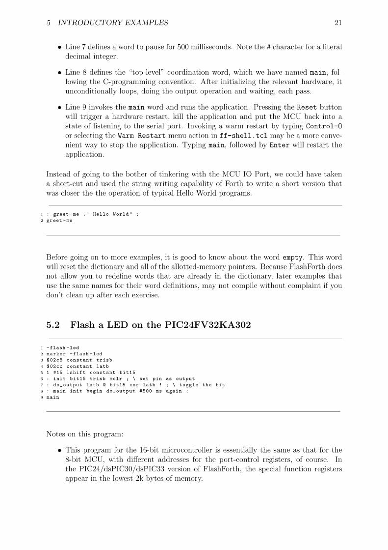
5.2 Flash a LED on the PIC24FV32KA302
1 -flash -led
2 marker -flash -led
3 $02c8 constant trisb
4 $02cc constant latb
5 1 #15 lshift constant bit15
6 : init bit15 trisb mclr ; \ set pin as output
7 : do_output latb @ bit15 xor latb ! ; \ toggle the bit
8 : main init begin do_output #500 ms again ;
9 main
Notes on this program:
• This program for the 16-bit microcontroller is essentially the same as that for the8-bit MCU, with different addresses for the port-control registers, of course. Inthe PIC24/dsPIC30/dsPIC33 version of FlashForth, the special function registersappear in the lowest 2k bytes of memory.

5 INTRODUCTORY EXAMPLES 22
• On line 5, we compute the bit pattern for selecting the MCU pin rather than writingit explicitly. We start with a 1 in the least-significant bit of the 16-bit word andthen shift it left 15 places, to produce the binary value %1000000000000000
• On line 7, we use 16-bit fetch @ and store ! operations because the hardware specialfunction registers on this microcontroller are 16 bits wide.
5.3 Flash a LED on the ATmega328P
1 -flash -led -avr
2 marker -flash -led -avr
3 \ PB5 is Arduino digital pin 13.
4 \ There is a LED attached to this pin on the Freetronics Eleven.
5
6 $0024 constant ddrb
7 $0025 constant portb
8 1 #5 lshift constant bit5
9
10 : init bit5 ddrb mset ; \ set pin as output
11 : do_output portb c@ bit5 xor portb c! ; \ toggle the bit
12 : main init begin do_output #500 ms again ;
13
14 main
Notes on this program:
• Again, except for the specific registers and bits, this program is the same as for theother MCUs. As for other high-level languages, we no longer have to think aboutthe specific machine architecture (usually).
• Because we are using load and store instructions, the special function registers startat address $20.
5 INTRODUCTORY EXAMPLES 23
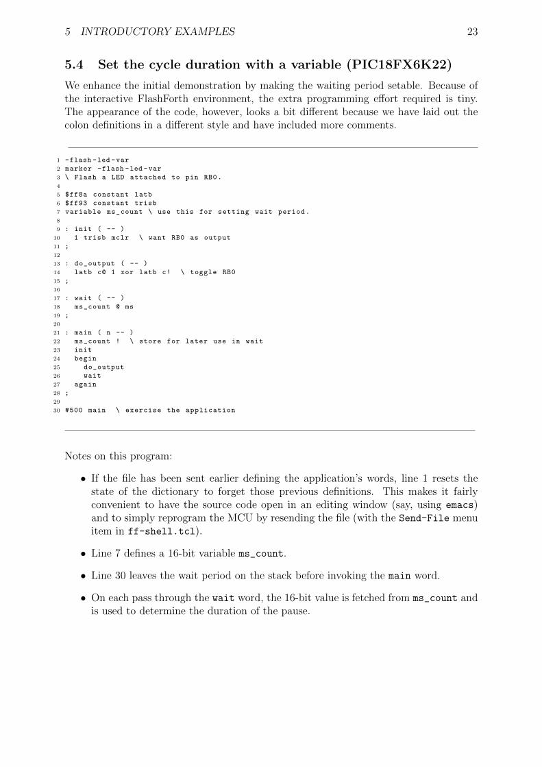
5.4 Set the cycle duration with a variable (PIC18FX6K22)
We enhance the initial demonstration by making the waiting period setable. Because ofthe interactive FlashForth environment, the extra programming effort required is tiny.The appearance of the code, however, looks a bit different because we have laid out thecolon definitions in a different style and have included more comments.
1 -flash -led -var
2 marker -flash -led -var
3 \ Flash a LED attached to pin RB0.
4
5 $ff8a constant latb
6 $ff93 constant trisb
7 variable ms_count \ use this for setting wait period.
8
9 : init ( -- )
10 1 trisb mclr \ want RB0 as output
11 ;
12
13 : do_output ( -- )
14 latb c@ 1 xor latb c! \ toggle RB0
15 ;
16
17 : wait ( -- )
18 ms_count @ ms
19 ;
20
21 : main ( n -- )
22 ms_count ! \ store for later use in wait
23 init
24 begin
25 do_output
26 wait
27 again
28 ;
29
30 #500 main \ exercise the application
Notes on this program:
• If the file has been sent earlier defining the application’s words, line 1 resets thestate of the dictionary to forget those previous definitions. This makes it fairlyconvenient to have the source code open in an editing window (say, using emacs)and to simply reprogram the MCU by resending the file (with the Send-File menuitem in ff-shell.tcl).
• Line 7 defines a 16-bit variable ms_count.
• Line 30 leaves the wait period on the stack before invoking the main word.
• On each pass through the wait word, the 16-bit value is fetched from ms_count andis used to determine the duration of the pause.

5 INTRODUCTORY EXAMPLES 24
5.5 Hello, World: Morse code
Staying with the minimal hardware of just a single LED attached to pin RB0 on thePIC18F26K22 or PIC18F46K22, we can make a proper “Hello World” application. Thefollowing program makes use of Forth’s colon definitions so that we can spell the messagedirectly in source code and have the MCU communicate that message in Morse code.
1 -hello -world
2 marker -hello -world
3 \ Flash a LED attached to pin RB0 , sending a message in Morse -code.
4
5 $ff8a constant latb
6 $ff93 constant trisb
7 variable ms_count \ determines the timing.
8
9 : init ( -- )
10 1 trisb mclr \ want RB0 as output
11 1 latb mclr \ initial state is off
12 ;
13
14 : led_on 1 latb mset ;
15 : led_off 1 latb mclr ;
16 : gap ms_count @ ms ; \ pause period
17 : gap2 gap gap ;
18 : dit led_on gap led_off gap2 ;
19 : dah led_on gap2 led_off gap2 ;
20
21 \ Have looked up the ARRL CW list for the following letters.
22 : H dit dit dit dit ;
23 : e dit ;
24 : l dit dit ;
25 : o dah dah dah ;
26 : W dit dah dah ;
27 : r dit dah dit ;
28 : d dah dit dit ;
29
30 : greet ( -- )
31 H e l l o gap W o r l d gap2
32 ;
33
34 : main ( n -- )
35 ms_count ! \ store for later use in gap
36 init
37 begin
38 greet
39 again
40 ;
41
42 #100 main \ exercise the application
6 READ AND REPORT AN ANALOG VOLTAGE 25
6 Read and report an analog voltage
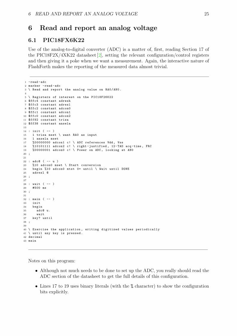
6.1 PIC18FX6K22
Use of the analog-to-digital converter (ADC) is a matter of, first, reading Section 17 ofthe PIC18F2X/4XK22 datasheet [2], setting the relevant configuration/control registersand then giving it a poke when we want a measurement. Again, the interactive nature ofFlashForth makes the reporting of the measured data almost trivial.
1 -read -adc
2 marker -read -adc
3 \ Read and report the analog value on RA0/AN0.
4
5 \ Registers of interest on the PIC18F26K22
6 $ffc4 constant adresh
7 $ffc3 constant adresl
8 $ffc2 constant adcon0
9 $ffc1 constant adcon1
10 $ffc0 constant adcon2
11 $ff92 constant trisa
12 $ff38 constant ansela
13
14 : init ( -- )
15 1 trisa mset \ want RA0 as input
16 1 ansela mset
17 %00000000 adcon1 c! \ ADC references Vdd , Vss
18 %10101111 adcon2 c! \ right -justified , 12-TAD acq -time , FRC
19 %00000001 adcon0 c! \ Power on ADC , looking at AN0
20 ;
21
22 : adc@ ( -- u )
23 %10 adcon0 mset \ Start conversion
24 begin %10 adcon0 mtst 0= until \ Wait until DONE
25 adresl @
26 ;
27
28 : wait ( -- )
29 #500 ms
30 ;
31
32 : main ( -- )
33 init
34 begin
35 adc@ u.
36 wait
37 key? until
38 ;
39
40 \ Exercise the application , writing digitized values periodically
41 \ until any key is pressed.
42 decimal
43 main
Notes on this program:
• Although not much needs to be done to set up the ADC, you really should read theADC section of the datasheet to get the full details of this configuration.
• Lines 17 to 19 uses binary literals (with the % character) to show the configurationbits explicitly.

6 READ AND REPORT AN ANALOG VOLTAGE 26
• Line 24 conditionally repeats testing of the DONE bit for the ADC.
• Line 25 fetches the full 10-bit result and leaves it on the stack for use after the adc@
word has finished. Because of the selected configuration of the ADC peripheral, thevalue will be right-justified in the 16-bit cell.
• Line 35 invokes the adc@ word and prints the numeric result.
• Line 37 checks if a character has come in from the serial terminal. If so, the loop isterminated and the main function returns control to the FlashForth interpreter.
6.2 PIC24FV32KA30X
The analog-to-digital converter on the PIC24-series microcontrollers is a little more com-plex than that on the PIC18 series. There are more features to select and so there aremore registers and bits to set, however, the essential set-up tasks are similar. The follow-ing script sets up some word definitions that were developed with a view to using them ina larger program. The particular words are more verbose but also carry more information.
1 -read -adc
2 marker -read -adc
3 \ Read and report the analog values on AN0 through AN3.
4
5 \ Registers of interest on the PIC24FV32KA30x
6 $0084 constant ifs0
7
8 $02c0 constant trisa
9 $02c2 constant porta
10 $02c4 constant lata
11 $02c6 constant odca
12
13 $02c8 constant trisb
14 $02ca constant portb
15 $02cc constant latb
16 $02ce constant odcb
17
18 $0300 constant adc1buf0
19 $0340 constant ad1con1
20 $0342 constant ad1con2
21 $0344 constant ad1con3
22 $0348 constant ad1chs
23
24 $04e0 constant ansa
25 $04e2 constant ansb
26
27 $0770 constant pmd1
28
29 \ bit masks
30 $0001 constant mADC1MD \ pmd1
31 $0001 constant mDONE \ ad1con1
32 $0002 constant mSAMP
33 $8000 constant mADON
34 $2000 constant mAD1IF
35
36
37 : adc.init ( -- )
38 $0003 trisa mset \ want RA0 , RA1 as input
39 $0003 ansa mset
40 $0003 trisb mset
41 $0003 ansb mset

6 READ AND REPORT AN ANALOG VOLTAGE 27
42 mADC1MD pmd1 mclr \ ensure module enabled
43 $0470 ad1con1 ! \ 12-bit , auto -convert
44 $0000 ad1con2 ! \ ADC references Vdd , Vss
45 $9f00 ad1con3 ! \ ADRC , 31-TAD acq -time
46 $0000 ad1chs ! \ neg input is Vss , pos input AN0
47 mADON ad1con1 mset \ Power on ADC
48 mAD1IF ifs0 mclr
49 ;
50
51 : adc.close ( -- )
52 mADON ad1con1 mclr
53 mAD1IF ifs0 mclr
54 ;
55
56 : adc.select ( u -- ) \ select positive input
57 $0003 and ad1chs ! \ limit selection to AN0 through AN3
58 ;
59
60 : adc@ ( -- u )
61 mDONE ad1con1 mclr
62 mSAMP ad1con1 mset \ Start sampling
63 begin mDONE ad1con1 mtst until \ Wait until done.
64 adc1buf0 @
65 ;
66
67 : [email protected] ( -- u )
68 0 \ start of sum
69 8 for adc@ + next
70 8 /
71 ;
72
73 : wait ( -- )
74 #500 ms
75 ;
76
77 : adc.test ( -- )
78 adc.init
79 begin
80 0 adc.select [email protected] u.
81 1 adc.select [email protected] u.
82 cr
83 wait
84 key? until
85 adc.close
86 ;
87
88 \ Exercise the application , writing digitized values periodically
89 \ until any key is pressed.
90 \ decimal
91 \ adc.test
Notes on this program:
• This script was part of a larger application for the monitoring of 2 pressure trans-ducers, hence the setting up of just RA0 and RA1 at the start of adc.init at lines38–41.
• To save power the peripheral modules of a PIC24 are, by default, disabled. Youneed to clear a module’s disable bit (line 42) to do anything with it, even settingconfiguration registers. The (separate) power-on bit still needs to be set to start upthe converter.

7 COUNTING BUTTON PRESSES 28
7 Counting button presses
Example of sensing a button press, with debounce in software.
1 \ Use a push -button on RB0 to get user input.
2 \ This button is labelled S3 on the PICDEM2+ board.
3 -pb-demo
4 marker -pb-demo
5
6 $ff81 constant portb
7 $ff8a constant latb
8 $ff93 constant trisb
9
10 variable count
11
12 : init ( -- )
13 %01 trisb mset \ RB0 as input
14 %10 trisb mclr \ RB1 as output
15 %10 latb mclr
16 ;
17 : RB1toggle ( -- )
18 latb c@ %10 xor latb c!
19 ;
20 : RB0@ ( -- c )
21 portb c@ %01 and
22 ;
23 : button? ( -- f )
24 \ Check for button press , with software debounce.
25 \ With the pull -up in place , a button press will give 0.
26 RB0@ if
27 0
28 else
29 #10 ms
30 RB0@ if 0 else -1 then
31 then
32 ;
33
34 : main ( -- )
35 0 count !
36 init
37 begin
38 button? if
39 RB1toggle
40 count @ 1+ count !
41 count @ .
42 #200 ms \ allow time to release button
43 then
44 cwd
45 key? until
46 ;
47
48 main \ exercise the application
Notes on this program:
• The main word clears the count variable, calls init to set up the hardware andthen loops, polling RB0 and incrementing value of the count variable only when thebutton gets pressed.
• If the pause after acknowledging the button press (line 42) is too long, we may loselater button press events. This depends on how frantically we press S3.

7 COUNTING BUTTON PRESSES 29
• Line 44 resets the watch-dog timer on each pass of the main loop. If we don’t pressthe RB0 button for a long time, the main loop would not otherwise pause and clearthe watch-dog timer. The watch-dog timer is cleared inside the ms word, however,if the timer expires before being cleared, the microcontroller would be reset and theFlashForth interpreter would restart.

8 COUNTING BUTTON PRESSES VIA INTERRUPTS 30
8 Counting button presses via interrupts
Instead of polling the RB0 pin attached to the push button, as in the previous example,let’s set up the hardware interrupt mechanism to invoke the increment action for us.
1 \ Use a push -button on RB0 to get user input , via an interrupt.
2 \ This button is labelled S3 on the PICDEM2+ board.
3 \ Don ’t have J6 connected because the LED on RB0 loads the pull -up.
4
5 -pb-interrupt
6 marker -pb -interrupt
7
8 $ff93 constant trisb
9 $fff2 constant intcon
10 $fff1 constant intcon2
11
12 variable count
13 variable last -count
14
15 : int0 -irq
16 [i
17 %10 intcon mtst \ INT0IF
18 if
19 count @ 1+ count !
20 %10 intcon mclr
21 then
22 i]
23 ;i
24
25 : init ( -- )
26 %01 trisb mset \ RB0 as input , a button press will give 0.
27 %01000000 intcon2 mclr \ interrupt on falling edge
28 [’] int0 -irq 0 int! \ install service word
29 %10 intcon mclr \ INT0IF cleared
30 %10000 intcon mset \ INT0 interrupt enable
31 ;
32
33 : main ( -- )
34 0 count !
35 init
36 begin
37 count @ last -count @ - \ change?
38 if
39 count @ dup last -count ! .
40 then
41 cwd
42 key? until
43 ;
44
45 main \ exercise the application
Notes on this program:
• Again, we use the variable named count as the variable to be incremented on press-ing the button that pulls RB0 low. The actual increment is done on line 19, insidethe interrupt service word int0-irq. The second variable, last-count, is used online 36 in the main word, to detect when the count variable changes.
• The init word sets up the bits to enable the INT0 external interrupt to fire on afalling edge at RB0.

8 COUNTING BUTTON PRESSES VIA INTERRUPTS 31
• On line 28 in the init word, the execution token for our interrupt service wordis stored as the high-priority interrupt vector. Because FlashForth supports onlyhigh-priority interrupts, the 0 is a dummy value but is still expected by the int!
word.
• Inside the interrupt-service word, we need to test the INT0IF interrupt flag to see ifit is our interrupt to handle and, if it is, do the appropriate work (of incrementingthe count variable) and clearing the interrupt flag. If you enable several interruptsources, you need to provide a test and action for each.
• The main word clears the count variable, calls init to set up the interrupt mecha-nism and then loops, emitting the value of the count variable only when it changes.

9 SCANNING A 4X3 MATRIX KEYPAD 32
9 Scanning a 4x3 matrix keypad
We connect a 4x3 matrix keypad to PORTB, using RB0, RB1 and RB2 to drive thecolumns while sensing the rows with RB4 through RB7. The schematic figure belowshows the arrangement of keys and pins.
1 2 3
4 5 6
7 8 9
* 0 #
pin 2, RB7
pin 7, RB6
pin 6, RB5
pin 4, RB4
pin 3 1 5RB0 RB1 RB2
To minimize hardware, we have used the weak pull-ups on PORTB. Pressing a key whileits column wire is held high does nothing, however, pressing a key on a column that isheld low will result in its row being pulled low.
1 -keypad
2 marker -keypad
3 \ Display key presses from a 4x3 (telephone -like) keypad
4 \ on PIC18F26K22 -I/SP
5
6 $ff81 constant portb
7 $ff8a constant latb
8 $ff93 constant trisb
9 $ff39 constant anselb
10 $ff61 constant wpub
11 $fff1 constant intcon2
12
13 : init ( -- )
14 0 latb c!
15 %00000000 anselb c! \ set as all digital I/O pins
16 %11110000 trisb c! \ RB7 -4 as input , RB3 -0 as output
17 %11110000 wpub c! \ pull -ups on RB7 -4
18 %10000000 intcon2 mclr \ turn on pull -ups
19 ;
20
21 flash
22 create key_chars
23 char 1 c, char 2 c, char 3 c,
24 char 4 c, char 5 c, char 6 c,
25 char 7 c, char 8 c, char 9 c,
26 char * c, char 0 c, char # c,
27 create key_scan_bytes
28 $7e c, $7d c, $7b c,
29 $be c, $bd c, $bb c,
30 $de c, $dd c, $db c,
31 $ee c, $ed c, $eb c,
32 ram
33
34 : scan_keys ( -- c )
35 \ Return ASCII code of key that is pressed
36 #12 for
37 key_scan_bytes r@ + c@
38 dup
39 latb c!
40 portb c@
41 = if
42 \ key must be pressed to get a match
43 key_chars r@ + c@
44 rdrop

9 SCANNING A 4X3 MATRIX KEYPAD 33
45 exit
46 then
47 next
48 0 \ no key was pressed
49 ;
50
51 : keypad@ ( -- c )
52 \ Read keypad with simple debounce.
53 \ ASCII code is left on stack.
54 \ Zero is returned for no key pressed or inconsistent scans.
55 scan_keys dup
56 #20 ms
57 scan_keys
58 = if exit else drop then
59 0 \ inconsistent scan results
60 ;
61
62 : main ( -- )
63 init
64 begin
65 keypad@
66 dup
67 0= if
68 drop \ no key pressed
69 else
70 emit
71 #300 ms \ don ’t repeat key too quickly
72 then
73 key? until
74 ;
Notes on this program:
• In lines 21–31, we make use of character arrays to store (into the program memory)the the ASCII code and the scan code for each key. The scan code is made up ofthe 3-bit column pattern to be applied to RB2-RB0 and the resulting 4-bit row-sense pattern (RB7-RB4) expected for the particular key if it is pressed. RB3 ismaintained high (and is of no consequence) for this 3-column keypad, however, itwould be used for a 4x4 keypad.
• Lines 36 and 47 make use of the for–next control construct to work through the setof 12 scan codes
• We should go further by making use a state-machine and also keeping track of thelast key pressed.

10 BASE WORDS FOR AN I2C MASTER 34
10 Base words for an I2C master
Here are some words for using I2C (or Two-wire) peripherals for each of the microcon-trollers in master mode. These words provide abstract the hardware registers and bits toprovide a common vocabulary for the interaction with I2C slave devices.
10.1 PIC18FX6K22
1 \ i2c -base -k22.txt
2 \ Low -level words for I2C master on PIC18F26K22
3 \
4 \ Modelled on the original i2c -base.txt for PIC18 ,
5 \ i2c -twi.frt from amforth and
6 \ the datasheet for Microchip PIC18F26K22.
7 \ Peter J. 2014 -11 -08
8
9 -i2c -base -k22
10 marker -i2c -base -k22
11 hex ram
12
13 \ Registers related to I2C operation of MSSP1
14 $ff3a constant anselc
15 $ff82 constant portc
16 $ff8b constant latc
17 $ff94 constant trisc
18 $ff9e constant pir1
19 $ffc5 constant ssp1con2
20 $ffc6 constant ssp1con1
21 $ffc7 constant ssp1stat
22 $ffc8 constant ssp1add
23 $ffc9 constant ssp1buf
24 $ffca constant ssp1msk
25 $ffcb constant ssp1con3
26
27 \ Masks for bits
28 %00000001 constant mSEN \ in ssp1con2
29 %00000010 constant mRSEN
30 %00000100 constant mPEN
31 %00001000 constant mRCEN
32 %00010000 constant mACKEN
33 %00100000 constant mACKDT
34 %01000000 constant mACKSTAT
35 %00100000 constant mSSP1EN \ in ssp1con1
36 %00000001 constant mBF \ in ssp1stat
37 %00001000 constant mSSP1IF \ in pir1
38
39 : i2c.init ( -- )
40 %00001000 ssp1con1 c! \ Master mode
41 [ Fcy #100 / 1- ] literal ssp1add c! \ Set clock frequency to 100 kHz
42 mSSP1IF pir1 mclr \ Clear interrupt bit
43 %00011000 trisc mset \ SCL1 on RC3 , SDA1 on RC4
44 %00011000 anselc mclr
45 mSSP1EN ssp1con1 mset \ Enable hardware
46 ;
47
48 : i2c.close ( -- )
49 mSSP1EN ssp1con1 mclr
50 mSSP1IF pir1 mclr
51 ;
52
53 : i2c.wait ( -- ) \ Wait for interrupt flag and clear it
54 begin mSSP1IF pir1 mtst until
55 mSSP1IF pir1 mclr
56 ;
57
58 : i2c.idle? ( -- f )

10 BASE WORDS FOR AN I2C MASTER 35
59 %00011111 ssp1con2 mtst \ ACKEN RCEN REN RSEN SEN
60 %100 ssp1stat mtst \ R/^W
61 or 0=
62 ;
63
64 : i2c.start ( -- ) \ Send start condition
65 begin i2c.idle? until
66 mSSP1IF pir1 mclr
67 mSEN ssp1con2 mset
68 i2c.wait
69 ;
70
71 : i2c.rsen ( -- ) \ Send repeated start condition
72 mSSP1IF pir1 mclr
73 mRSEN ssp1con2 mset
74 i2c.wait
75 ;
76
77 : i2c.stop ( -- ) \ Send stop condition
78 mSSP1IF pir1 mclr
79 mPEN ssp1con2 mset
80 i2c.wait
81 ;
82
83 : i2c.buf.full? ( -- f )
84 mBF ssp1stat mtst
85 ;
86
87 \ Write one byte to bus , leaves ACK bit.
88 \ A value of 0 indicates ACK was received from slave device.
89 : i2c.c! ( c -- f )
90 begin i2c.buf.full? 0= until
91 ssp1buf c!
92 begin i2c.buf.full? 0= until
93 begin i2c.idle? until
94 ssp1con2 c@ mACKSTAT and
95 ;
96
97 \ Send ack bit.
98 : i2c.ack.seq ( -- )
99 mACKEN ssp1con2 mset
100 begin mACKEN ssp1con2 mtst 0= until
101 ;
102
103 \ Read one byte and ack for another.
104 : [email protected] ( -- c )
105 mRCEN ssp1con2 mset
106 begin i2c.buf.full? until
107 mACKDT ssp1con2 mclr i2c.ack.seq \ ack
108 ssp1buf c@
109 ;
110
111 \ Read one last byte.
112 : [email protected] ( -- c )
113 mRCEN ssp1con2 mset
114 begin i2c.buf.full? until
115 mACKDT ssp1con2 mset i2c.ack.seq \ nack
116 ssp1buf c@
117 ;
118
119 \ Address slave for writing , leaves true if slave ready.
120 : i2c.addr.write ( 7-bit -addr -- f )
121 1 lshift 1 invert and \ Build full byte with write -bit as 0
122 i2c.start i2c.c! 0=
123 ;
124
125 \ Address slave for reading , leaves true if slave ready.
126 : i2c.addr.read ( 7-bit -addr -- f )
127 1 lshift 1 or \ Build full byte with read -bit as 1
128 i2c.start i2c.c! 0=
129 ;

10 BASE WORDS FOR AN I2C MASTER 36
130
131 \ Detect presence of device , leaving true if device present , 0 otherwise.
132 \ We actually fetch a byte if the slave has acknowledged , then discard it.
133 : i2c.ping? ( 7-bit -addr -- f )
134 i2c.addr.read if [email protected] drop true else false then
135 ;
10.2 PIC24FV32KA30X
1 \ i2c -base -pic24fv32ka30x.txt
2 \ Low -level words for I2C master on PIC24FV32KA302 and KA301
3 \
4 \ Modelled on i2c -base.txt for PIC18 , i2c -twi.frt from amforth
5 \ the Microchip PIC24 Family Reference Manual
6 \ and the datasheet for PIC24FV32KA304 family.
7 \ Peter J. 2015 -09 -23
8
9 -i2c -base
10 marker -i2c -base
11 hex ram
12
13 \ Registers related to I2C operation of MSSP1
14 $0086 constant ifs1
15 $0200 constant i2c1rcv
16 $0202 constant i2c1trn
17 $0204 constant i2c1brg
18 $0206 constant i2c1con
19 $0208 constant i2c1stat
20 $020a constant i2c1add
21 $020c constant i2c1msk
22 $02c8 constant trisb
23 $02ca constant portb
24 $02cc constant latb
25 $02ce constant odcb
26 $04e2 constant ansb
27 $0770 constant pmd1
28
29 \ Masks for bits
30 $8000 constant mI2CEN \ in i2c1con
31 %000001 constant mSEN
32 %000010 constant mRSEN
33 %000100 constant mPEN
34 %001000 constant mRCEN
35 %010000 constant mACKEN
36 %100000 constant mACKDT
37 $8000 constant mACKSTAT \ in i2c1stat
38 $4000 constant mTRSTAT
39 $0400 constant mBCL
40 $0080 constant mIWCOL
41 $0040 constant mI2COV
42 %0001 constant mTBF
43 %0010 constant mRBF
44 %0010 constant mMI2C1IF \ in ifs1
45
46 $0100 constant mRB8 \ SCL1 on RB8
47 $0200 constant mRB9 \ SDA1 on RB9
48
49 : i2c.init ( -- )
50 $80 pmd1 mclr \ Enable the I2C1 module
51 [ Fcy #100 / Fcy #10000 / - 1- ] literal i2c1brg c! \ Set clock to 100 kHz
52 mMI2C1IF ifs1 mclr \ Clear interrupt bit for master operation
53 %1100000000 trisb mset \ SCL1 on RB8 , SDA1 on RB9
54 %1100000000 odcb mset
55 mI2CEN i2c1con mset \ Enable hardware

10 BASE WORDS FOR AN I2C MASTER 37
56 ;
57
58 : i2c.close ( -- )
59 mI2CEN i2c1con mclr
60 mMI2C1IF ifs1 mclr
61 ;
62
63 : i2c.bus.reset ( -- )
64 \ Manually reset the slave devices.
65 \ For use when a slave just won ’t let SDA1 go.
66 i2c.close
67 mRB9 trisb mset \ leave SDA1 float
68 mRB9 odcb mset
69 mRB8 trisb mclr \ drive SCL1 with digital output
70 mRB8 odcb mset
71 9 for
72 mRB8 latb mclr 1 ms
73 mRB8 latb mset 1 ms
74 next
75 \ stop condition
76 mRB8 latb mclr
77 mRB9 trisb mclr
78 mRB9 latb mclr 1 ms
79 mRB8 latb mset
80 mRB9 latb mset 1 ms
81 \ release bus
82 mRB8 trisb mset
83 mRB9 trisb mset
84 ;
85
86 : i2c.wait ( -- ) \ Wait for interrupt flag and clear it
87 begin mMI2C1IF ifs1 mtst until
88 mMI2C1IF ifs1 mclr
89 ;
90
91 : i2c.idle? ( -- f )
92 %00011111 i2c1con mtst \ ACKEN RCEN REN RSEN SEN
93 0=
94 ;
95
96 : i2c.start ( -- ) \ Send start condition
97 begin i2c.idle? until
98 mMI2C1IF ifs1 mclr
99 mSEN i2c1con mset
100 i2c.wait
101 ;
102
103 : i2c.rsen ( -- ) \ Send repeated start condition
104 mMI2C1IF ifs1 mclr
105 mRSEN i2c1con mset
106 i2c.wait
107 ;
108
109 : i2c.stop ( -- ) \ Send stop condition
110 mMI2C1IF ifs1 mclr
111 mPEN i2c1con mset
112 i2c.wait
113 ;
114
115 : i2c.tbuf.full? ( -- f )
116 mTBF i2c1stat mtst
117 ;
118
119 : i2c.rbuf.full? ( -- f )
120 mRBF i2c1stat mtst
121 ;
122
123 \ Write one byte to bus , leaves ACK bit.
124 \ A value of 0 indicates ACK was received from slave device.
125 : i2c.c! ( c -- f )
126 begin i2c.tbuf.full? 0= until
10 BASE WORDS FOR AN I2C MASTER 38
127 mMI2C1IF ifs1 mclr
128 i2c1trn c!
129 \ We wait for the interrupt because just waiting for the buffer
130 \ to be empty is unreliable if we look too soon.
131 i2c.wait
132 begin i2c.idle? until
133 i2c1stat @ mACKSTAT and
134 ;
135
136 \ Send ack bit.
137 : i2c.ack.seq ( -- )
138 mACKEN i2c1con mset
139 begin mACKEN i2c1con mtst 0= until
140 ;
141
142 \ Read one byte and ack for another.
143 : [email protected] ( -- c )
144 mRCEN i2c1con mset
145 begin i2c.rbuf.full? until
146 mACKDT i2c1con mclr i2c.ack.seq \ ack
147 i2c1rcv c@
148 ;
149
150 \ Read one last byte.
151 : [email protected] ( -- c )
152 mRCEN i2c1con mset
153 begin i2c.rbuf.full? until
154 mACKDT i2c1con mset i2c.ack.seq \ nack
155 i2c1rcv c@
156 ;
157
158 \ Address slave for writing , leaves true if slave ready.
159 : i2c.addr.write ( 7-bit -addr -- f )
160 1 lshift 1 invert and \ Build full byte with write -bit as 0
161 i2c.start i2c.c! 0=
162 ;
163
164 \ Address slave for reading , leaves true if slave ready.
165 : i2c.addr.read ( 7-bit -addr -- f )
166 1 lshift 1 or \ Build full byte with read -bit as 1
167 i2c.start i2c.c! 0=
168 ;
169
170 \ Detect presence of device ,
171 \ leaving true if device present , 0 otherwise.
172 \ We actually fetch a byte if the slave has acknowledged.
173 : i2c.ping? ( 7-bit -addr -- f )
174 i2c.addr.read if [email protected] drop true else false then
175 ;
10.3 ATmega328P
1 \ i2c -base -avr.txt
2 \ Low -level words for TWI/I2C on Atmega328P.
3 \
4 \ Modelled on i2c -twi.frt from amforth ,
5 \ i2c_base.txt for FlashForth on PIC18
6 \ and the Atmel datasheet , of course.
7 \ Peter J. 2014 -10 -27
8
9 -i2c -base
10 marker -i2c -base
11 hex ram
12
10 BASE WORDS FOR AN I2C MASTER 39
13 \ Two -Wire -Interface Registers
14 $b8 constant TWBR
15 $b9 constant TWSR
16 $bb constant TWDR
17 $bc constant TWCR
18
19 \ Bits in the Control Register
20 %10000000 constant mTWINT
21 %01000000 constant mTWEA
22 %00100000 constant mTWSTA
23 %00010000 constant mTWSTO
24 %00001000 constant mTWWC
25 %00000100 constant mTWEN
26 %00000001 constant mTWIE
27
28 : i2c.init ( -- ) \ Set clock frequency to 100kHz
29 %11 TWSR mclr \ prescale value = 1
30 [ Fcy #100 / #16 - 2/ ] literal TWBR c!
31 mTWEN TWCR mset
32 ;
33
34 : i2c.wait ( -- ) \ Wait for operation to complete
35 \ When TWI operations are done , the hardware sets
36 \ the TWINT interrupt flag , which we will poll.
37 begin TWCR c@ mTWINT and until
38 ;
39
40 : i2c.start ( -- ) \ Send start condition
41 [ mTWINT mTWEN or mTWSTA or ] literal TWCR c!
42 i2c.wait
43 ;
44
45 : i2c.rsen ( -- ) \ Send repeated start condition
46 i2c.start \ AVR doesn ’t distinguish
47 ;
48
49 : i2c.stop ( -- ) \ Send stop condition
50 [ mTWINT mTWEN or mTWSTO or ] literal TWCR c!
51 ;
52
53 \ Write one byte to bus , returning 0 if ACK was received , -1 otherwise.
54 : i2c.c! ( c -- f )
55 i2c.wait \ Must have TWINT high to write data
56 TWDR c!
57 [ mTWINT mTWEN or ] literal TWCR c!
58 i2c.wait
59 \ Test for arrival of an ACK depending on what was sent.
60 TWSR c@ $f8 and $18 xor 0= if 0 exit then \ SLA+W
61 TWSR c@ $f8 and $28 xor 0= if 0 exit then \ data byte
62 TWSR c@ $f8 and $40 xor 0= if 0 exit then \ SLA+R
63 -1 \ Something other than an ACK resulted
64 ;
65
66 \ Read one byte and ack for another.
67 : [email protected] ( -- c )
68 [ mTWINT mTWEN or mTWEA or ] literal TWCR c!
69 i2c.wait
70 TWDR c@
71 ;
72
73 \ Read one last byte.
74 : [email protected] ( -- c )
75 [ mTWINT mTWEN or ] literal TWCR c!
76 i2c.wait
77 TWDR c@
78 ;
79
80 \ Address slave for writing , leaving true if slave ready.
81 : i2c.addr.write ( 7-bit -addr -- f )
82 1 lshift 1 invert and \ Build full byte with write -bit as 0
83 i2c.start i2c.c! if false else true then

10 BASE WORDS FOR AN I2C MASTER 40
84 ;
85
86 \ Address slave for reading , leaving true if slave ready.
87 : i2c.addr.read ( 7-bit -addr -- f )
88 1 lshift 1 or \ Build full byte with read -bit as 1
89 i2c.start i2c.c! if false else true then
90 ;
91
92 \ Detect presence of device , leaving true if slave responded.
93 \ If the slave ACKs the read request , fetch one byte only.
94 : i2c.ping? ( 7-bit -addr -- f )
95 1 lshift 1 or \ Build full byte with read -bit as 1
96 i2c.start i2c.c! 0= if [email protected] drop true else false then
97 ;
10.4 Notes on using the words
• The word i2c.init is used to set up the I2C master peripheral for further activities.
• I2C conversations begin by addressing a slave device for either reading or writing.The words i2c.addr.read and i2c.addr.write are provided for this waking ofthe slave. They leave a flag on the stack to indicate whether the slave deviceacknowledged being addressed. If the slave device responded appropriately, youmay proceed to read or write bytes.
• There are two words for reading a byte from the bus. [email protected] reads a byte andasserts an acknowledge (ACK) to indicate to the slave device that another byte willbe read subsequently. [email protected] reads a byte and asserts a NACK to indicateto the slave that no more bytes are wanted.
• The word to sending a byte to the slave device is i2c.c!. This word leaves a flagto indicate the state of the ACK bit following the action of sending the byte. If theslave asserted ACK, the flag will be 0. You may drop this flag if it not of interestto you.
• There are lower-level words i2c.start, i2c.rsen and i2c.stop to assert start,restart and stop conditions respectively. These are used within the higher-levelwords mentioned above.
• The utility word i2c.ping? attempts to address a slave and read a byte. It leavestrue if the slave responds, else false.
• Sometimes when tinkering with a new I2C device, you can get into a state of con-fusion such that the slave device will end up in some intermediate state waitingfor clock signals.3 In this state, the slave device will no longer respond in a waythat the master peripheral understands. Rather than cycle the power to reset theslave device, it may be convenient to force the clocking of the data bits through thebus and get the slave device back into an idle state. The word i2c.reset.bus (ini2c-base-pic24fv32ka30x.txt) is provided to automate this forced clocking.
3This happens more often than I would like to admit.

10 BASE WORDS FOR AN I2C MASTER 41
10.5 Detecting I2C devices
Building on the base words for a particular microcontroller, the following program workson all of the microcontrollers discussed in this tutorial guide. It is convenient to run thisprogram to to see if the device of interest is responding. There’s no point trying to havea conversation with a device that doesn’t respond to being addressed.
1 \ i2c -detect.txt
2 \ Detect presence of all possible devices on I2C bus.
3 \ Only the 7 bit address schema is supported.
4 \
5 \ Copied from amForth distribution (lib/hardware /)
6 \ and lightly edited to suit FlashForth 5.0 on AVR.
7 \ Builds upon i2c -base -xxxx.txt and doloop.txt.
8 \ Peter J. 2014 -10 -27
9
10 -i2c -detect
11 marker -i2c -detect
12
13 \ not all bitpatterns are valid 7bit i2c addresses
14 : i2c.7 bitaddr? ( a -- f) $7 $78 within ;
15
16 : i2c.detect ( -- )
17 base @ hex
18 \ header line
19 cr 5 spaces $10 0 do i 2 u.r loop
20 $80 0 do
21 i $0f and 0= if
22 cr i 2 u.r [char] : emit space
23 then
24 i i2c.7 bitaddr? if
25 i i2c.ping? if \ does device respond?
26 i 2 u.r
27 else
28 ." -- "
29 then
30 else
31 ." "
32 then
33 loop
34 cr base !
35 ;
36
37 \ With a lone Microchip TC74A0 sitting on the bus ,
38 \ the output looks like
39 \ i2c.init ok<$,ram >
40 \ i2c.detect
41 \ 00 01 02 03 04 05 06 07 08 09 0a 0b 0c 0d 0e 0f
42 \ 00 : -- -- -- -- -- -- -- -- --
43 \ 10 : -- -- -- -- -- -- -- -- -- -- -- -- -- -- -- --
44 \ 20 : -- -- -- -- -- -- -- -- -- -- -- -- -- -- -- --
45 \ 30 : -- -- -- -- -- -- -- -- -- -- -- -- -- -- -- --
46 \ 40 : -- -- -- -- -- -- -- -- 48 -- -- -- -- -- -- --
47 \ 50 : -- -- -- -- -- -- -- -- -- -- -- -- -- -- -- --
48 \ 60 : -- -- -- -- -- -- -- -- -- -- -- -- -- -- -- --
49 \ 70 : -- -- -- -- -- -- -- --
50 \ ok <$,ram >
51 \ i2c.stop ok<$,ram >

11 USING I2C TO GET TEMPERATURE MEASUREMENTS 42
11 Using I2C to get temperature measurements
Using the words in i2c-base-k22.txt to control the MSSP peripheral in master mode,one may talk to the TC74A5 temperature measurement chip on the PICDEM 2 PLUSand report sensor temperature.
1 \ Read temperature from TC74 on PICDEM2+ board with PIC18F46K22 -I/P.
2 \ Modelled on Mikael Nordman ’s i2c_tcn75.txt.
3 \ This program requires i2c -base -k22.txt to be previously loaded.
4 -read -tc74
5 marker -read -tc74
6
7 %1001101 constant addr -TC74A5 \ 7-bit address for the chip
8
9 : tc74 -init ( -- )
10 \ Selects the temperature register for subsequent reads.
11 addr -TC74A5 i2c.addr.write if 0 i2c.c! drop then i2c.stop
12 ;
13 : sign -extend ( c -- n )
14 \ If the TC74 has returned a negative 8-bit value ,
15 \ we need to sign extend to 16-bits with ones.
16 dup $7f > if $ff80 or then
17 ;
18 : degrees@ ( -- n )
19 \ Wake the TC74 and receive its register value.
20 addr -TC74A5 i2c.addr.read if [email protected] sign -extend else 0 then
21 ;
22 : tc74 -main ( -- )
23 i2c.init
24 tc74 -init
25 begin
26 degrees@ .
27 #1000 ms
28 key? until
29 ;
30
31 \ Now , report temperature in degrees C
32 \ while we warm up the TC74 chip with our fingers ...
33 decimal tc74 -main
With a Saleae Logic Analyser connected to the pins of the TC74A5, we can see the I2Csignals as a result of calling the tc74-init word.
A little later on, the degrees@ word is invoked. The returned binary value of 0b00010101corresponds to the very pleasant 21oC that exists in the back shed as this text is beingwritten.
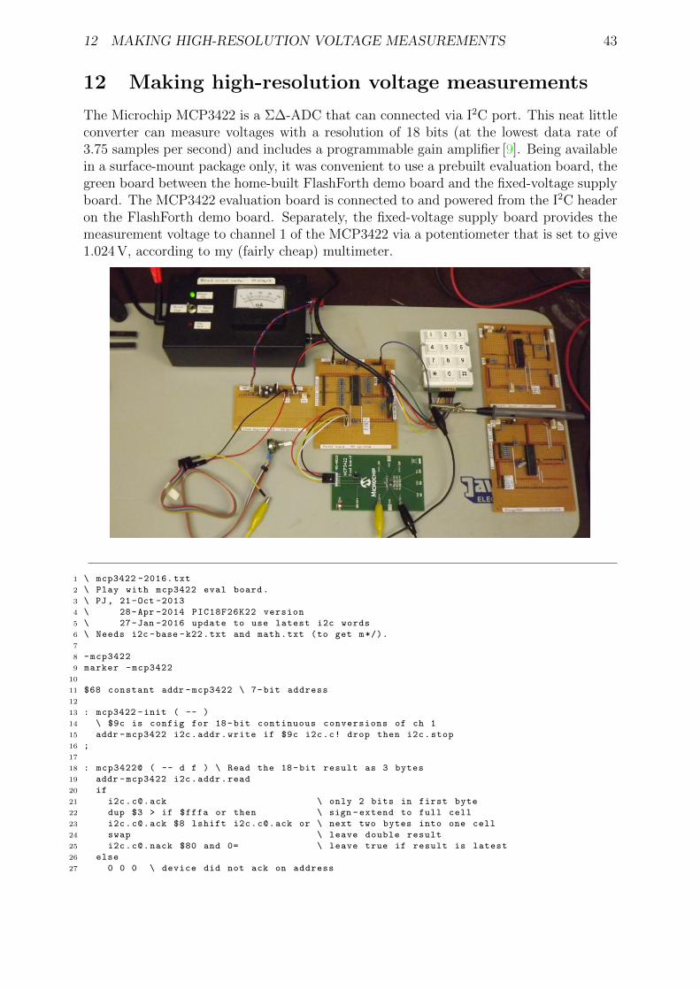
12 MAKING HIGH-RESOLUTION VOLTAGE MEASUREMENTS 43
12 Making high-resolution voltage measurements
The Microchip MCP3422 is a Σ∆-ADC that can connected via I2C port. This neat littleconverter can measure voltages with a resolution of 18 bits (at the lowest data rate of3.75 samples per second) and includes a programmable gain amplifier [9]. Being availablein a surface-mount package only, it was convenient to use a prebuilt evaluation board, thegreen board between the home-built FlashForth demo board and the fixed-voltage supplyboard. The MCP3422 evaluation board is connected to and powered from the I2C headeron the FlashForth demo board. Separately, the fixed-voltage supply board provides themeasurement voltage to channel 1 of the MCP3422 via a potentiometer that is set to give1.024 V, according to my (fairly cheap) multimeter.
1 \ mcp3422 -2016. txt
2 \ Play with mcp3422 eval board.
3 \ PJ, 21-Oct -2013
4 \ 28-Apr -2014 PIC18F26K22 version
5 \ 27-Jan -2016 update to use latest i2c words
6 \ Needs i2c -base -k22.txt and math.txt (to get m*/).
7
8 -mcp3422
9 marker -mcp3422
10
11 $68 constant addr -mcp3422 \ 7-bit address
12
13 : mcp3422 -init ( -- )
14 \ $9c is config for 18-bit continuous conversions of ch 1
15 addr -mcp3422 i2c.addr.write if $9c i2c.c! drop then i2c.stop
16 ;
17
18 : mcp3422@ ( -- d f ) \ Read the 18-bit result as 3 bytes
19 addr -mcp3422 i2c.addr.read
20 if
21 [email protected] \ only 2 bits in first byte
22 dup $3 > if $fffa or then \ sign -extend to full cell
23 [email protected] $8 lshift [email protected] or \ next two bytes into one cell
24 swap \ leave double result
25 [email protected] $80 and 0= \ leave true if result is latest
26 else
27 0 0 0 \ device did not ack on address

12 MAKING HIGH-RESOLUTION VOLTAGE MEASUREMENTS 44
28 then
29 ;
30
31 : microvolts ( d1 -- d2 )
32 \ The least -significant bit corresponds to 15.625 microvolts
33 #125 #8 m*/
34 ;
35
36 : (d.3) ( d -- )
37 swap over dabs
38 <# # # # [char] . hold #s rot sign #>
39 ;
40
41 : report ( d f -- ) \ Assuming decimal , print millivolt value
42 cr if ." new " else ." old " then
43 microvolts (d.3) type space ." mV "
44 ;
45
46 : mcp3422 -run ( -- )
47 decimal
48 i2c.init mcp3422 -init
49 begin
50 mcp3422@ report
51 #1000 ms
52 key? until
53 hex
54 ;
Notes on this program:
• mcp3422-run is the top-level word that initializes the hardware, then periodicallyreads the MCP3422 data and reports the voltage (in millivolts) to the user terminal.The program runs until a key is pressed.
• The converted value is read from the MCP3422 as and 18-bit value in 2-complementformat. The word mcp3422@ reads the data as three bytes from the I2C port andthen shuffles it into a double-cell value that is left on the stack, along with a flag toindicate whether the value sent by the MCP3422 happened to be the latest data. Ifthe MCP3422 did not respond to being addressed, zeros will be left on the stack inplace of the expected data.
• The value is scaled to microvolts and then the resultant double value is output usingthe pictured numeric output to have 3 decimal places so that it looks like a millivoltreading. Several lines from the terminal look like the following:
new 1028.031 mV
new 1028.062 mV
new 1028.046 mV
• This program builds upon the i2c-base-k22 words in order to communicate withthe MCP3422. The code for scaling of the measured data requires the mixed-scaleword m*/ from the file math.txt provided by FlashForth.

13 AN I2C SLAVE EXAMPLE 45
13 An I2C slave example
The MSSP in the PIC18F26K22 can also be used in slave mode. Here, the FlashForthdemo board is presented as an I2C slave device to an Aardvark serial interface, acting asmaster. The UART communication is provided by a Future Technology Devices Interna-tional USB TTL-serial cable.
The core of the program is the i2c service word which is invoked each time a serial-portevent is flagged by the SSPIF bit in the PIR1 flag register. This word is an implementationof the state look-up approach detailed in the Microchip Application Note AN734 [10]. Therest of the program is there to provide (somewhat) interesting data for the I2C masterto read and to do something (light a LED) when the master writes suitable data to theslave.
1 -i2c -slave
2 marker -i2c -slave
3 \ Make the FlashForth 26K22 demo board into an I2C slave.
4 \ An I2C master can read and write to a buffer here ,
5 \ the least -significant bit of the first byte controls
6 \ the LED attached to pin RB0.
7 \
8 \ Needs core.txt loaded.
9
10 $ff81 constant portb
11 $ff82 constant portc
12 $ff8a constant latb
13 $ff93 constant trisb
14 $ff94 constant trisc
15 $ff3a constant anselc
16
17 : led_on ( -- )
18 %00000001 latb mset
19 ;
20 : led_off ( -- )
21 %00000001 latb mclr
22 ;
23 : err_led_on ( -- )
24 %00000010 latb mset
25 ;
26 : err_led_off ( -- )
27 %00000010 latb mclr
28 ;
29
30 \ Establish a couple of buffers in RAM , together with index variables.
31 ram
32 8 constant buflen
33 \ Receive buffer for incoming I2C data.
34 create rbuf buflen allot
35 variable rindx
36 : init_rbuf ( -- )
37 rbuf buflen erase
38 0 rindx !
39 ;
40 : incr_rindx ( -- ) \ increment with wrap -around
41 rindx @ 1 +
42 dup buflen = if drop 0 then
43 rindx !
44 ;
45 : save_to_rbuf ( c -- )
46 rbuf rindx @ + c!
47 incr_rindx
48 ;
49
50 \ Send buffer with something interesting for the I2C master to read.

13 AN I2C SLAVE EXAMPLE 46
51 create sbuf buflen allot
52 variable sindx
53 : incr_sindx ( -- ) \ increment with wrap -around
54 sindx @ 1 +
55 dup buflen = if drop 0 then
56 sindx !
57 ;
58 : init_sbuf ( -- ) \ fill with counting integers , for interest
59 buflen
60 for
61 r@ 1+
62 sbuf r@ + c!
63 next
64 0 sindx !
65 ;
66
67 \ I2C -related definitions and code
68 $ffc5 constant sspcon2
69 $ffc6 constant sspcon1
70 $ffc7 constant sspstat
71 $ffc8 constant sspadd
72 $ffc9 constant sspbuf
73 $ff9e constant pir1
74
75 \ PIR1 bits
76 %00001000 constant sspif
77
78 \ SSPSTAT bits
79 %00000001 constant bf
80 %00000100 constant r_nw
81 %00001000 constant start_bit
82 %00010000 constant stop_bit
83 %00100000 constant d_na
84 %01000000 constant cke
85 %10000000 constant smp
86
87 d_na start_bit or r_nw or bf or constant stat_mask
88
89 \ SSPCON1 bits
90 %00010000 constant ckp
91 %00100000 constant sspen
92 %01000000 constant sspov
93 %10000000 constant wcol
94
95 \ SSPCON2 bits
96 %00000001 constant sen
97
98 : i2c_init ( -- )
99 %11000 anselc mclr \ enable digital -in on RC3 ,RC4 (SCL1 ,SDA1)
100 %00011000 trisc mset \ RC3==SCL RC4==SDA
101 %00000110 sspcon1 c! \ Slave mode with 7-bit address
102 sen sspcon2 mset \ Clock stretching enabled
103 smp sspstat mset \ Slew -rate disabled
104 $52 1 lshift sspadd c! \ Slave address
105 sspen sspcon1 mset \ Enable MSSP peripheral
106 ;
107
108 : release_clock ( -- )
109 ckp sspcon1 mset
110 ;
111
112 : i2c_service ( -- )
113 \ Check the state of the I2C peripheral and react.
114 \ See App Note 734 for an explanation of the 5 states.
115 \
116 \ State 1: i2c write operation , last byte was address.
117 \ D_nA=0, S=1, R_nW=0, BF=1
118 sspstat c@ stat_mask and %00001001 =
119 if
120 sspbuf @ drop
121 init_rbuf

13 AN I2C SLAVE EXAMPLE 47
122 release_clock
123 exit
124 then
125 \ State 2: i2c write operation , last byte was data.
126 \ D_nA=1, S=1, R_nW=0, BF=1
127 sspstat c@ stat_mask and %00101001 =
128 if
129 sspbuf c@ save_to_rbuf
130 release_clock
131 exit
132 then
133 \ State 3: i2c read operation , last byte was address.
134 \ D_nA=0, S=1, R_nW=1
135 sspstat c@ %00101100 and %00001100 =
136 if
137 sspbuf c@ drop
138 0 sindx !
139 wcol sspcon1 mclr
140 sbuf sindx @ + c@ sspbuf c!
141 release_clock
142 incr_sindx
143 exit
144 then
145 \ State 4: i2c read operation , last byte was outgoing data.
146 \ D_nA=1, S=1, R_nW=1, BF=0
147 sspstat c@ stat_mask and %00101100 =
148 ckp sspcon1 mtst 0=
149 and
150 if
151 wcol sspcon1 mclr
152 sbuf sindx @ + c@ sspbuf c!
153 release_clock
154 incr_sindx
155 exit
156 then
157 \ State 5: master NACK , slave i2c logic reset.
158 \ From AN734: D_nA=1, S=1, BF=0, CKP=1, however ,
159 \ we use just D_nA=1 and CKP=1, ignoring START bit.
160 \ This is because master may have already asserted STOP
161 \ before we service the final NACK on a read operation.
162 d_na sspstat mtst 0 > ckp sspcon1 mtst 0 > and
163 stop_bit sspstat mtst or
164 if
165 exit \ Nothing needs to be done.
166 then
167 \ We shouldn ’t arrive here ...
168 err_led_on
169 cr ." Error "
170 ." sspstat " sspstat c@ u.
171 ." sspcon1 " sspcon1 c@ u.
172 ." sspcon2 " sspcon2 c@ u.
173 cr
174 begin again \ Hang around until watch -dog resets MCU.
175 ;
176
177
178 : init ( -- )
179 %00000011 trisb mclr \ want RB0 ,RB1 as output pins
180 init_rbuf
181 init_sbuf
182 i2c_init
183 led_on err_led_on #200 ms led_off err_led_off
184 ;
185
186 : main ( -- )
187 cr ." Start I2C slave "
188 init
189 begin
190 sspif pir1 mtst
191 if
192 sspif pir1 mclr

13 AN I2C SLAVE EXAMPLE 48
193 i2c_service
194 then
195 rbuf c@ %00000001 and
196 if led_on else led_off then
197 cwd
198 key? until
199 ;
200
201 \ ’ main is turnkey
With a Saleae Logic Analyser connected, we can see the I2C signals as a result of writingthe byte 0x01 to turn on the LED. The following figure shows the data and clock signalsfrom the time that the master asserts the START condition (green circle) until it assertsthe STOP condition (as indicated by the red square).
The clock frequency is 100kHz and there is a 138µs gap between the ninth clock pulse ofthe address byte and the start of the pulses for the data byte. This gives an indication ofthe time needed to service each SSPIF event.
A little later on, the Aardvark reads two bytes from the bus, as shown here.
Zooming in, to show the finer annotation, the same signals are shown below.
Again, the inter-byte gap is 138µs resulting in about 200µs needed to transfer each byte.This effective speed of 5 kbytes/s should be usable for many applications, since the I2Cbus is typically used for low speed data transfer.
Notes on this program:
• Need to load core.txt before the source code of the i2c-slave.txt.
• Slave examples found in documentation on the Web usually have the service functionwritten in the context of an interrupt service routine. The MSSP can be servicedquite nicely without resorting to the use of interrupts, however, you still have tocheck and clear the SSPIF bit for each event.
• The implementation of the test for State 5 (Master NACK) is slightly different tothat described in AN734 because it was found that the master would assert an I2Cbus stop after the final NACK of a read operation but before the MCU could servicethe SSPIF event. This would mean that STOP was the most recent bus conditionseen by the MSSP and the START and STOP bits set to reflect this. In the figuresshown above, there is only about 12µs between the ninth clock pulse for the secondread data byte and the Aardvark master asserting the STOP condition on the bus.This period is very much shorter than the (approx.) 140µs period needed by theslave firmware to service the associated SSPIF event.

14 SPEED OF OPERATION – BIT BANGING 49
14 Speed of operation – bit banging
All of this nice interaction and convenience has some costs. One cost is the number ofMCU instruction cycles needed to process the Forth words. To visualize this cost, thefollowing program defines a word blink-forth which toggles an IO pin using the high-level FlashForth words that fetch and store bit patterns into the port latch register. Analternative word blink-asm uses assembler instructions to achieve an equivalent effect,but faster, and a third word blink-bits uses the FlashForth bit0: and bit1: words tocreate high-level bit-manipulation words that also achieve full machine speed.
14.1 PIC18F26K22
1 -speed -test
2 marker -speed -test
3 \ Waggle RB1 as quickly as we can , in both high - and low -level code.
4 \ Before sending this file , we should send asm.txt so that we have
5 \ the clrwdt , word available. We also need bit.txt.
6
7 $ff8a constant latb
8 $ff93 constant trisb
9
10 : initRB1
11 %10 trisb mclr \ RB1 as output
12 %10 latb mclr \ initially known state
13 ;
14
15 \ high -level bit fiddling , presumably slow
16 : blink -forth ( -- )
17 initRB1
18 begin
19 %10 latb c! 0 latb c! \ one cycle , on and off
20 %10 latb c! 0 latb c!
21 %10 latb c! 0 latb c!
22 %10 latb c! 0 latb c!
23 cwd \ We have to kick the watch dog ourselves.
24 again
25 ;
26
27 \ low -level bit fiddling , via assembler
28 : blink -asm ( -- )
29 initRB1
30 [
31 begin ,
32 latb 1 a, bsf , latb 1 a, bcf , \ one cycle , on and off
33 latb 1 a, bsf , latb 1 a, bcf ,
34 latb 1 a, bsf , latb 1 a, bcf ,
35 latb 1 a, bsf , latb 1 a, bcf ,
36 clrwdt , \ kick the watch dog
37 again ,
38 ]
39 ;
40
41 \ high -level bit fiddling with named bits
42 latb #1 bit1: RB1 -hi inlined
43 latb #1 bit0: RB1 -lo inlined
44 : blink -bits ( -- )
45 initRB1
46 begin
47 RB1 -hi RB1 -lo \ one cycle
48 RB1 -hi RB1 -lo
49 RB1 -hi RB1 -lo
50 RB1 -hi RB1 -lo
51 cwd

14 SPEED OF OPERATION – BIT BANGING 50
52 again
53 ;
Notes on this program:
• We have had to worry about clearing the watch-dog timer. In the early examples,the FlashForth interpreter was passing through the pause state often enough to keepthe watch-dog happy. The words in this example give the FlashForth interpreter notime to pause so we are responsible for clearing the watch-dog timer explicitly.
• In the source code config file for the specific MCU, the watch-dog timer postscaleis set to 256. With a 31.25 kHz oscillator frequency, this leads to a default timeoutperiod of a little over 1 second (32µs× 128× 256).
• For the PIC18 MCU, the internal oscillator of 16 MHz was multiplied by the PLL toget 64 MHz oscillator driving the MCU. With 4 clock cycles per instruction cycle,this gave an instruction period TCY = 62.5 ns. Current consumption by the micro-controller was about 14 mA, roughly double the value when the interpreter is notdoing much, just waiting for input.
• The screen image on the left shows the output signal for running the high-levelblink-forth word while the image on the right uses the assembler words.
• For the blink-forth word, one on+off cycle of the LED executes in 6 words andis seen (in the oscilloscope record) to require about 50 instruction cycles. So, onaverage, each of these threaded Forth words is executed in about 8 MCU instruc-tion cycles. Note that this overhead includes the cost of using 16-bit cells for thedata. Extra machine instructions are used to handle the upper bytes. In otherapplications, where we actually want to handle 16-bit data, this will no longer be apenalty.
• The assembler version has no overhead and the cycle time for the MCU instructionsdefines the period of the output signal. One on-off cycle requires 2 instructions sowe see a short 125 ns period. This is fast enough that the capacitive loading on theoutput pin is noticeable in the oscilloscope trace. Also, the time required for themachine instructions to clear the watch-dog timer and the instruction jump back tothe start of the loop now shows up clearly in the oscilloscope record.

14 SPEED OF OPERATION – BIT BANGING 51
• The oscilloscope record for the blink-bits word is shown here.
With the bit-manipulation words RB1-hi and RB1-lo being inlined, they also achievefull machine speed because the generated code is essentially the same as for blink-asm.
14.2 PIC24FV32KA302
1 -speed -test
2 marker -speed -test
3 \ For the PIC24FV32KA302 , waggle RB15 as quickly as we can ,
4 \ in both high - and low -level code.
5 \ Remember to load bit.txt before this file.
6
7 $02c8 constant trisb
8 $02ca constant portb
9 $02cc constant latb
10 $02ce constant odcb
11
12 1 #15 lshift constant bit15
13
14 : initRB15
15 bit15 trisb mclr \ RB15 as output
16 bit15 latb mclr \ initially known state
17 ;
18
19 \ high -level bit fiddling , presumably slow
20 : blink -forth ( -- )
21 initRB15
22 begin
23 bit15 latb ! 0 latb ! \ one cycle , on and off
24 bit15 latb ! 0 latb !
25 bit15 latb ! 0 latb !
26 bit15 latb ! 0 latb !
27 cwd \ We have to kick the watch dog ourselves.
28 again
29 ;
30
31 \ low -level bit fiddling , via assembler
32 : blink -asm ( -- )
33 initRB15
34 [
35 begin ,
36 #15 latb bset , #15 latb bclr , \ one cycle , on and off
37 #15 latb bset , #15 latb bclr ,
38 #15 latb bset , #15 latb bclr ,
39 #15 latb bset , #15 latb bclr ,
40 ] cwd [ \ kick the watch dog
41 again ,
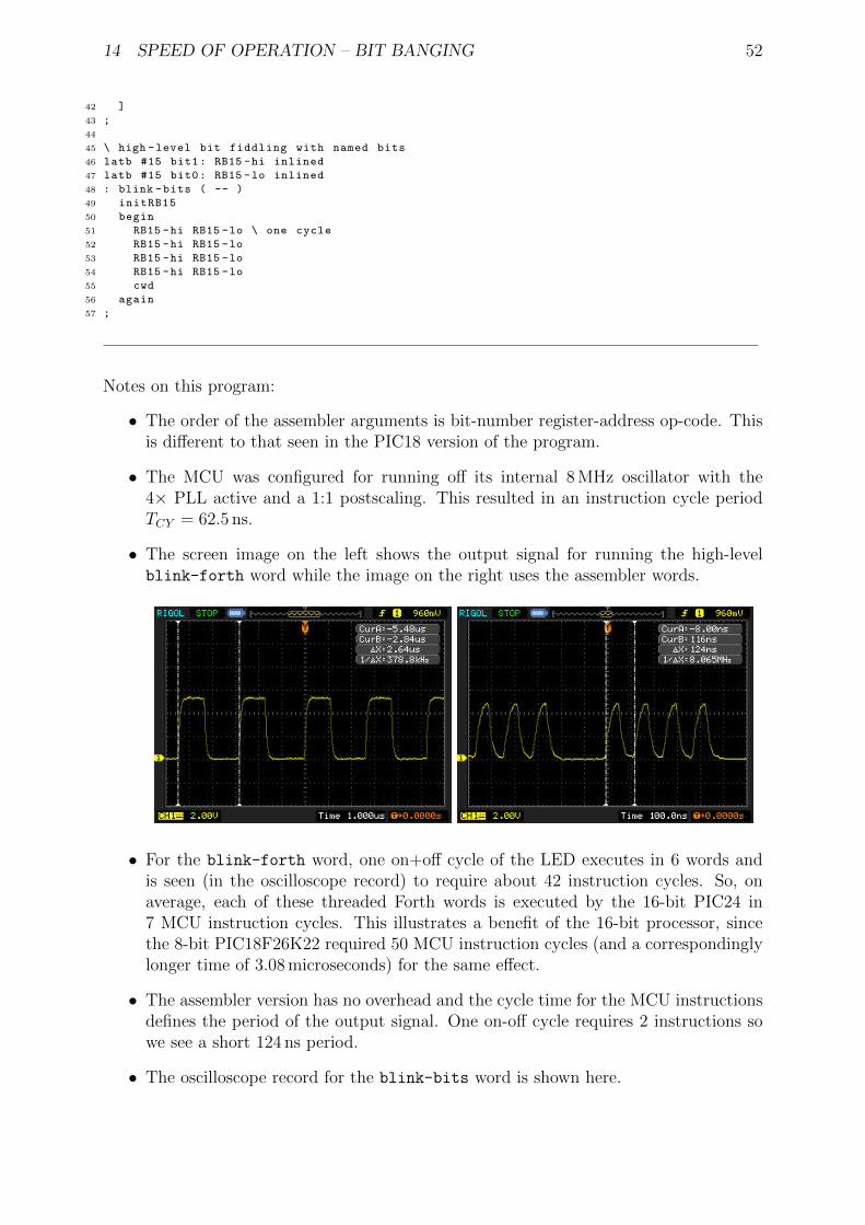
14 SPEED OF OPERATION – BIT BANGING 52
42 ]
43 ;
44
45 \ high -level bit fiddling with named bits
46 latb #15 bit1: RB15 -hi inlined
47 latb #15 bit0: RB15 -lo inlined
48 : blink -bits ( -- )
49 initRB15
50 begin
51 RB15 -hi RB15 -lo \ one cycle
52 RB15 -hi RB15 -lo
53 RB15 -hi RB15 -lo
54 RB15 -hi RB15 -lo
55 cwd
56 again
57 ;
Notes on this program:
• The order of the assembler arguments is bit-number register-address op-code. Thisis different to that seen in the PIC18 version of the program.
• The MCU was configured for running off its internal 8 MHz oscillator with the4× PLL active and a 1:1 postscaling. This resulted in an instruction cycle periodTCY = 62.5 ns.
• The screen image on the left shows the output signal for running the high-levelblink-forth word while the image on the right uses the assembler words.
• For the blink-forth word, one on+off cycle of the LED executes in 6 words andis seen (in the oscilloscope record) to require about 42 instruction cycles. So, onaverage, each of these threaded Forth words is executed by the 16-bit PIC24 in7 MCU instruction cycles. This illustrates a benefit of the 16-bit processor, sincethe 8-bit PIC18F26K22 required 50 MCU instruction cycles (and a correspondinglylonger time of 3.08 microseconds) for the same effect.
• The assembler version has no overhead and the cycle time for the MCU instructionsdefines the period of the output signal. One on-off cycle requires 2 instructions sowe see a short 124 ns period.
• The oscilloscope record for the blink-bits word is shown here.

14 SPEED OF OPERATION – BIT BANGING 53
Again, the bit-manipulation words RB15-hi and RB15-lo also achieve full machinespeed.
14.3 ATmega328P
1 -speed -test
2 marker -speed -test
3 \ Waggle PB5 as quickly as we can , in both high - and low -level code.
4 \ Before sending this file , we should send asm.txt and bit.txt.
5
6 $0024 constant ddrb
7 $0025 constant portb \ RAM address
8 $0005 constant portb -io \ IO -space address
9 1 #5 lshift constant bit5
10
11 : initPB5
12 bit5 ddrb mset \ set pin as output
13 bit5 portb mclr \ initially known state
14 ;
15
16 : cwd ( -- ) [ wdr , ] ; inlined \ we might want to reset the watchdog
17
18 \ high -level bit fiddling , presumably slow
19 : blink -forth ( -- )
20 initPB5
21 begin
22 bit5 portb c! 0 portb c! \ one cycle , on and off
23 bit5 portb c! 0 portb c!
24 bit5 portb c! 0 portb c!
25 bit5 portb c! 0 portb c!
26 cwd
27 again
28 ;
29
30 \ low -level bit fiddling , via assembler
31 : blink -asm ( -- )
32 initPB5
33 [
34 begin ,
35 portb -io #5 sbi , portb -io #5 cbi , \ one cycle , on and off
36 portb -io #5 sbi , portb -io #5 cbi ,
37 portb -io #5 sbi , portb -io #5 cbi ,
38 portb -io #5 sbi , portb -io #5 cbi ,
39 wdr ,
40 again ,
41 ]
42 ;
43
44 \ high -level bit fiddling with named bits

14 SPEED OF OPERATION – BIT BANGING 54
45 portb #5 bit1: PB5 -hi inlined
46 portb #5 bit0: PB5 -lo inlined
47 : blink -bits ( -- )
48 initPB5
49 begin
50 PB5 -hi PB5 -lo \ one cycle
51 PB5 -hi PB5 -lo
52 PB5 -hi PB5 -lo
53 PB5 -hi PB5 -lo
54 cwd
55 again
56 ;
Notes on this program:
• Except for names, this code is essentially the same as for the PIC18 and PIC24versions of the exercise. FlashForth abstracts away much of the instruction-setarchitecture of the microcontroller, leaving us to focus on twiddling the bits of theperipheral hardware.
• The MCU was configured for running with the 16 MHz crystal, which resulted in amachine clock cycle period TCY = 62.5 ns.
• The screen image on the left shows the output signal for running the high-levelblink-forth word while the image on the right uses the assembler words.
• For the blink-forth, one on+off cycle of the LED executes in 6 words and is seen (inthe oscilloscope record) to require about 90 instruction cycles. So, on average, eachof these threaded Forth words is executed by the 8-bit AVR in 15 MCU instructioncycles.
• The assembler version has no overhead and the cycle time for the MCU instructionsdefines the period of the output signal. One on-off cycle requires 2 instructions(sbi and cbi) each requiring 2 clock cycles, so we see a short, quarter-microsecondperiod.
• The oscilloscope record for the blink-bits word is shown here.
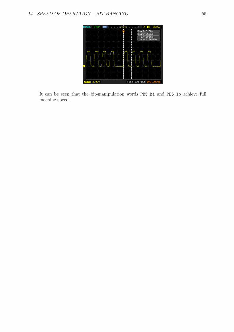
14 SPEED OF OPERATION – BIT BANGING 55
It can be seen that the bit-manipulation words PB5-hi and PB5-lo achieve fullmachine speed.

15 DRIVING AN HITACHI-44780 LCD CONTROLLER 56
15 Driving an Hitachi-44780 LCD controller
The LCD in the photograph on page 7 was driven with the following code. During thedevelopment of this example, a lesson was relearned – that of reading the data sheet [11]carefully :)
1 \ Exercise LCD on PICDEM2+ board.
2 \ Remember to load bit.txt before this file.
3 -xlcd
4 marker -xlcd
5
6 $ff80 constant porta
7 $ff89 constant lata
8 $ff92 constant trisa
9 $ff83 constant portd
10 $ff8c constant latd
11 $ff95 constant trisd
12
13 \ The LCD is operated in nibble mode.
14 \ RA1 = Enable (E) pin
15 \ RA2 = Read/Write (RW) pin
16 \ RA3 = Register Select (RS) pin
17 \ RD0 = DB4 on LCD
18 \ RD1 = DB5
19 \ RD2 = DB6
20 \ RD3 = DB7
21
22 portd constant dataport
23 lata #1 bit0: Elo
24 lata #1 bit1: Ehi
25 lata #2 bit0: RWlo
26 lata #2 bit1: RWhi
27 lata #3 bit0: RSlo
28 lata #3 bit1: RShi
29
30 : data -port -in ( -- )
31 trisd c@ $0f or trisd c!
32 ;
33
34 : data -port -out ( -- )
35 trisd c@ $f0 and trisd c!
36 ;
37
38 : put -nibble ( c -- )
39 \ Make lower 4 bits of c appear on data port pins.
40 $0f and
41 dataport c@ $f0 and
42 or
43 dataport c!
44 ;
45
46 : short -delay ( -- )
47 18 for r@ drop next ;
48
49 : Estrobe ( -- )
50 Ehi short -delay Elo
51 ;
52
53 : lcd -getc ( -- c )
54 \ Read the LCD register in two nibbles.
55 \ Remember to select the register line before calling this word.
56 data -port -in
57 RWhi short -delay
58 Ehi short -delay dataport c@ #4 lshift Elo short -delay \ high nibble
59 Ehi short -delay dataport c@ Elo short -delay \ low nibble
60 or \ assemble full byte and leave it on the stack
61 RWlo short -delay
62 ;

15 DRIVING AN HITACHI-44780 LCD CONTROLLER 57
63
64 : lcd -ready? ( -- f )
65 \ Read the command register and check busy bit.
66 RSlo short -delay
67 lcd -getc $80 and 0=
68 ;
69
70 : wait -for -lcd ( -- )
71 begin lcd -ready? cwd until
72 ;
73
74 : lcd -putc ( c -- )
75 \ Write the LCD register in two nibbles.
76 \ Remember to select the register line before calling this word.
77 dup $f0 and #4 rshift \ high nibble left on top of stack
78 data -port -out
79 RWlo short -delay
80 put -nibble short -delay Estrobe short -delay
81 $0f and \ low nibble now left on top of stack
82 put -nibble short -delay Estrobe short -delay
83 data -port -in
84 ;
85
86 : lcd -clear ( -- )
87 wait -for -lcd
88 RSlo short -delay
89 %00000001 lcd -putc
90 ;
91
92 : lcd -home ( -- )
93 wait -for -lcd
94 RSlo short -delay
95 %00000010 lcd -putc
96 ;
97
98 : lcd -goto ( c -- )
99 \ Set the specified 7-bit data memory address.
100 wait -for -lcd
101 RSlo short -delay
102 $80 or \ sets the highest bit for the command
103 lcd -putc
104 ;
105
106 : lcd -init ( -- )
107 data -port -in
108 Elo RWlo RSlo
109 %00001110 trisa mclr \ RS, RW and E as output
110 30 ms \ power -on delay
111 \ Begin "initialization by instruction"
112 \ Presumably , the LCD is in 8-bit interface mode.
113 %0011 put -nibble Estrobe 5 ms
114 %0011 put -nibble Estrobe 1 ms
115 %0011 put -nibble Estrobe 1 ms
116 \ Function set for 4-bit interface; it is still in 8-bit mode.
117 %0010 put -nibble Estrobe 1 ms
118 \ Now , we should be in 4-bit interface mode.
119 \ Function set for 4-bit interface , 2 display lines 5x7 font.
120 wait -for -lcd
121 %00101000 lcd -putc
122 \ Increment cursor after each byte , don ’t shift display.
123 wait -for -lcd
124 %00000110 lcd -putc
125 \ Display off
126 wait -for -lcd
127 %00001000 lcd -putc
128 \ Display clear
129 %00000001 lcd -putc
130 5 ms
131 \ End of "initialization by instruction"
132 \ Enable cursor and display , no blink.
133 wait -for -lcd
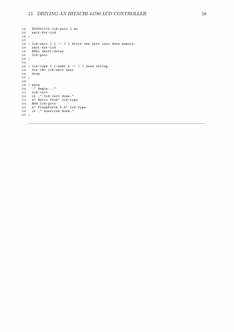
15 DRIVING AN HITACHI-44780 LCD CONTROLLER 58
134 %00001110 lcd -putc 1 ms
135 wait -for -lcd
136 ;
137
138 : lcd -emit ( c -- ) \ Write the byte into data memory.
139 wait -for -lcd
140 RShi short -delay
141 lcd -putc
142 ;
143
144 : lcd -type ( c-addr n -- ) \ send string
145 for c@+ lcd -emit next
146 drop
147 ;
148
149 : main
150 ." Begin ..."
151 lcd -init
152 cr ." lcd -init done."
153 s" Hello from" lcd -type
154 $40 lcd -goto
155 s" FlashForth 5.0" lcd -type
156 cr ." exercise done."
157 ;

REFERENCES 59
References
[1] Mikael Nordman. FLASHFORTH: for PIC and Atmega. URL http://flashforth.com,[email protected], 2014.
[2] Microchip Technology Inc. PIC18(L)F2X/4XK22 data sheet 28/40/44-pin, low-power, high-performance microcontrollers with XLP technology. DatasheetDS41412F, Microchip Technology Inc., www.microchip.com, 2012.
[3] Microchip Technology Inc. PIC24FV32KA304 FAMILY 20/28/44/48-pin, generalpurpose, 16-bit flash microcontrollers with XLP technology. Datasheet DS39995D,Microchip Technology Inc., www.microchip.com, 2013.
[4] Atmel. Atmel 8-bit Microcontroller with 4/8/16/32KBytes In-System ProgrammableFlash ATmega48A; ATmega48PA; ATmega88A; ATmega88PA; ATmega168A;ATmega168PA; ATmega328; ATmega328P. Datasheet 8271GAVR02/2013,www.atmel.com, 2013.
[5] L. Brodie and Forth Inc. Starting Forth: An introduction to the Forth Language andoperating system for beginners and professionals, 2nd Ed. Prentice Hall, EnglewoodCliffs, New Jersey, 1987.
[6] S. Pelc. Programming Forth. Microprocessor Engineering Limited, 2011.
[7] E. K. Conklin and E. D. Rather. Forth Programmer’s Handbook, 3rd Ed. Forth Inc.,California, 2007.
[8] Peter Jacobs, Peter Zawasky, and Mikael Nordman. Elements of FlashForth. Schoolof Mechanical and Mining Engineering Technical Report 2013/08, The University ofQueensland, Brisbane, May 2013.
[9] Microchip Technology Inc. MCP3422/3/4: 18-bit, multi-channel ∆Σ analog-to-digital converter with I2C interface and on-board reference. Datasheet DS22088C,Microchip Technology Inc., www.microchip.com, 2009.
[10] S. Bowling and N. Raj. Using the PIC devices SSP and MSSP modules for slave I2Ccommunication. Application Note AN734, Microchip Technology Inc., 2008.
[11] Hitachi. HD44780U (LCD-II) (Dot Matrix Liquid Crystal Display Controller/Driver).Datasheet ADE-207-272(Z) ’99.9 Rev. 0.0, Hitachi., 1999.

A USING OTHER TERMINAL PROGRAMS ON LINUX 60
A Using other terminal programs on Linux
As discussed in Section 4, interaction with the programmed MCU is via the serial port.There are a number of generic terminal emulation programs that will communicate viaa serial port. On a linux machine the cutecom terminal program is very convenient. Ithas a line-oriented input that doesn’t send the text to the MCU until you press the enterkey. This allows for editing of the line before committing it to the MCU and convenientrecall of previous lines. GtkTerm is available as more conventional terminal program.The following images shows the GtkTerm window just after sending the content of theflash-led.txt file to the PIC18F26K22. The device name of /dev/ttyUSB0 refers tothe USB-to-serial interface that was plugged one of the PC’s USB ports. It is convenientto start GtkTerm with the command
$ sudo gtkterm
and then adjust the communication settings via the Configuration → Port menu itemand its associated dialog window.
There is also a send-file capability and, importantly, the capability to set the period be-tween lines of text that are sent to the serial port so as to not overwhelm the FlashForthMCU. Although USB-to-serial interfaces usually implement software Xon-Xoff handshak-ing, my experience of using them with a minimal 3-wire connection (GND, RX and TX)has been variable. When sending large files, an end-of-line delay of a few tens of millisec-onds has usually been found adequate, however, there have been times that a file wouldnot successfully load until the end-of-line pause was increased to 300 milliseconds. ForGtkTerm, this setting is under the Advanced Configuration Options in the port con-figuration dialog, as shown below. This end-of-line delay makes the transfer of large filesslow, however, the text still scrolls past quickly but is now at a pace where it is possible tofollow the dialog and know how well the compilation is going. Building your applicationcode incrementally, with small files, is a good thing.

A USING OTHER TERMINAL PROGRAMS ON LINUX 61