A Survey of CubeSat Communication Systems: 2009 2012 · PDF fileA Survey of CubeSat...
41
A Survey of CubeSat Communication Systems: 2009–2012 Bryan Klofas (KF6ZEO) SRI International [email protected] Kyle Leveque (KG6TXT) CubeSat Research, LLC. [email protected] April 2013 Abstract This paper is a short survey of the communication subsystems of CubeSats successfully launched into orbit between the Minotaur 1 launch in May 2009 and the ELaNa-6/NROL- 36 launch in September 2012. Detailed information about the radios, data rates, antennas, and ground stations is included. The transition from amateur satellite service to experimental service for US CubeSats is discussed. We make recommendations to increase the chance of communications success. 1
-
Upload
trinhkhanh -
Category
Documents
-
view
229 -
download
4
Transcript of A Survey of CubeSat Communication Systems: 2009 2012 · PDF fileA Survey of CubeSat...

A Survey of CubeSat Communication Systems: 2009–2012
Bryan Klofas (KF6ZEO)SRI International
Kyle Leveque (KG6TXT)CubeSat Research, [email protected]
April 2013
Abstract
This paper is a short survey of the communication subsystems of CubeSats successfullylaunched into orbit between the Minotaur 1 launch in May 2009 and the ELaNa-6/NROL-36 launch in September 2012. Detailed information about the radios, data rates, antennas,and ground stations is included. The transition from amateur satellite service to experimentalservice for US CubeSats is discussed. We make recommendations to increase the chance ofcommunications success.
1

Contents
1 Introduction 4
2 United States Licensing Requirements 4
3 Recommendations 6
4 Satellite Comparison 6
5 Satellite Detail 105.1 Minotaur-1 . . . . . . . . . . . . . . . . . . . . . . . . . . . . . . . . . . . . . . . . . 10
5.1.1 AeroCube-3 . . . . . . . . . . . . . . . . . . . . . . . . . . . . . . . . . . . . . 105.1.2 CP6 . . . . . . . . . . . . . . . . . . . . . . . . . . . . . . . . . . . . . . . . . 115.1.3 HawkSat-1 . . . . . . . . . . . . . . . . . . . . . . . . . . . . . . . . . . . . . 115.1.4 PharmaSat . . . . . . . . . . . . . . . . . . . . . . . . . . . . . . . . . . . . . 11
5.2 ISILaunch 01/PSLV-C14 . . . . . . . . . . . . . . . . . . . . . . . . . . . . . . . . . . 125.2.1 BEESAT-1 . . . . . . . . . . . . . . . . . . . . . . . . . . . . . . . . . . . . . 125.2.2 UWE-2 . . . . . . . . . . . . . . . . . . . . . . . . . . . . . . . . . . . . . . . 135.2.3 ITUpSAT1 . . . . . . . . . . . . . . . . . . . . . . . . . . . . . . . . . . . . . 135.2.4 SwissCube . . . . . . . . . . . . . . . . . . . . . . . . . . . . . . . . . . . . . . 13
5.3 H-IIA F17 . . . . . . . . . . . . . . . . . . . . . . . . . . . . . . . . . . . . . . . . . . 145.3.1 Hayato . . . . . . . . . . . . . . . . . . . . . . . . . . . . . . . . . . . . . . . 145.3.2 Waseda-SAT2 . . . . . . . . . . . . . . . . . . . . . . . . . . . . . . . . . . . . 155.3.3 Negai-Star . . . . . . . . . . . . . . . . . . . . . . . . . . . . . . . . . . . . . . 15
5.4 NLS-6/PSLV-C15 . . . . . . . . . . . . . . . . . . . . . . . . . . . . . . . . . . . . . . 155.4.1 TIsat-1 . . . . . . . . . . . . . . . . . . . . . . . . . . . . . . . . . . . . . . . 165.4.2 StudSat . . . . . . . . . . . . . . . . . . . . . . . . . . . . . . . . . . . . . . . 16
5.5 STP-S26 . . . . . . . . . . . . . . . . . . . . . . . . . . . . . . . . . . . . . . . . . . . 175.5.1 RAX-1 . . . . . . . . . . . . . . . . . . . . . . . . . . . . . . . . . . . . . . . . 175.5.2 O/OREOS . . . . . . . . . . . . . . . . . . . . . . . . . . . . . . . . . . . . . 185.5.3 NanoSail-D2 . . . . . . . . . . . . . . . . . . . . . . . . . . . . . . . . . . . . 18
5.6 Falcon 9-002 . . . . . . . . . . . . . . . . . . . . . . . . . . . . . . . . . . . . . . . . . 195.6.1 Perseus (4) . . . . . . . . . . . . . . . . . . . . . . . . . . . . . . . . . . . . . 195.6.2 QbX (2) . . . . . . . . . . . . . . . . . . . . . . . . . . . . . . . . . . . . . . . 195.6.3 SMDC-ONE . . . . . . . . . . . . . . . . . . . . . . . . . . . . . . . . . . . . 205.6.4 Mayflower . . . . . . . . . . . . . . . . . . . . . . . . . . . . . . . . . . . . . . 20
5.7 ELaNa-1/Taurus XL . . . . . . . . . . . . . . . . . . . . . . . . . . . . . . . . . . . . 215.8 PSLV-C18 . . . . . . . . . . . . . . . . . . . . . . . . . . . . . . . . . . . . . . . . . . 22
5.8.1 Jugnu . . . . . . . . . . . . . . . . . . . . . . . . . . . . . . . . . . . . . . . . 225.9 ELaNa-3/NPP . . . . . . . . . . . . . . . . . . . . . . . . . . . . . . . . . . . . . . . 22
5.9.1 AubieSat-1 . . . . . . . . . . . . . . . . . . . . . . . . . . . . . . . . . . . . . 235.9.2 DICE (2) * . . . . . . . . . . . . . . . . . . . . . . . . . . . . . . . . . . . . . 235.9.3 HRBE . . . . . . . . . . . . . . . . . . . . . . . . . . . . . . . . . . . . . . . . 245.9.4 M-Cubed . . . . . . . . . . . . . . . . . . . . . . . . . . . . . . . . . . . . . . 255.9.5 RAX-2 . . . . . . . . . . . . . . . . . . . . . . . . . . . . . . . . . . . . . . . . 25
5.10 Vega VV01 . . . . . . . . . . . . . . . . . . . . . . . . . . . . . . . . . . . . . . . . . 255.10.1 Xatcobeo . . . . . . . . . . . . . . . . . . . . . . . . . . . . . . . . . . . . . . 26
2

5.10.2 ROBUSTA . . . . . . . . . . . . . . . . . . . . . . . . . . . . . . . . . . . . . 265.10.3 e-st@r . . . . . . . . . . . . . . . . . . . . . . . . . . . . . . . . . . . . . . . . 265.10.4 Goliat . . . . . . . . . . . . . . . . . . . . . . . . . . . . . . . . . . . . . . . . 275.10.5 PW-Sat . . . . . . . . . . . . . . . . . . . . . . . . . . . . . . . . . . . . . . . 275.10.6 Masat-1 . . . . . . . . . . . . . . . . . . . . . . . . . . . . . . . . . . . . . . . 275.10.7 UniCubeSat-GG . . . . . . . . . . . . . . . . . . . . . . . . . . . . . . . . . . 28
5.11 ELaNa-6/NROL-36 . . . . . . . . . . . . . . . . . . . . . . . . . . . . . . . . . . . . . 285.11.1 SMDC-ONE (2) . . . . . . . . . . . . . . . . . . . . . . . . . . . . . . . . . . 295.11.2 AeroCube-4 (3) . . . . . . . . . . . . . . . . . . . . . . . . . . . . . . . . . . . 295.11.3 Aeneas . . . . . . . . . . . . . . . . . . . . . . . . . . . . . . . . . . . . . . . . 305.11.4 CSSWE . . . . . . . . . . . . . . . . . . . . . . . . . . . . . . . . . . . . . . . 305.11.5 CP5 . . . . . . . . . . . . . . . . . . . . . . . . . . . . . . . . . . . . . . . . . 305.11.6 CXBN . . . . . . . . . . . . . . . . . . . . . . . . . . . . . . . . . . . . . . . . 315.11.7 CINEMA . . . . . . . . . . . . . . . . . . . . . . . . . . . . . . . . . . . . . . 315.11.8 Re . . . . . . . . . . . . . . . . . . . . . . . . . . . . . . . . . . . . . . . . . . 32
6 Conclusion 33
Bibliography 34
3

1 Introduction
This paper is an update to an earlier survey of CubeSat Communications [1]. The current papersurveys the communications subsystems on CubeSats launched from May 2009 to September 2012,clearly showing that the communication system is one major limiting factor for CubeSats.
Chapter 2 describes some of the licensing requirements for CubeSats built by US developers.Chapter 3 provides recommendations for new and existing CubeSat teams to increase their chancesof a successful project. Chapter 4 is a condensed table of all the CubeSats described in Chapter 5of this paper, which details the communication subsystems of the 49 CubeSats launched from May2009 to September 2012.
2 United States Licensing Requirements
As identified in 2002 [2, 3], spectrum licensing takes the longest amount of time for CubeSatcommunications, often longer than building and testing the satellite. Until 2011, the FederalCommunications Commission (FCC) was content to let CubeSats use the amateur satellite service,even if they didn’t follow all of the amateur radio regulations in Part 97.
The CubeSat licensing issue was brought to the forefront during the launch of ELaNa-3/NPPin October 2011. For a variety of reasons, the FCC did not file the correct international notificationpaperwork with the International Telecommunications Union (ITU) for the CubeSats on this launch.Several days before launch, the ITU notified the FCC about this. The CubeSat teams scrambledto fill out all the paperwork, and all documents were submitted to the ITU before launch [5].
Due to this mix-up, the FCC became more active at the CubeSat Summer Workshop duringthe Small Satellite Conference in Logan, Utah, in August 2012. A representative from the FCCsuggested that most CubeSat teams should get an experimental license instead of amateur, basedon Section 97.113, which prohibits any type of payment to the licensee or control operators of thespacecraft [4].
FCC met in November 2012 with representatives from NASA, NRO, and the CubeSat commu-nity to prevent this licensing issue in the future. The results of this meeting are contained in FCCPublic Notice DA-13-445A1, “Guidance on Obtaining Licenses for Small Satellites.” This documenttouches on who is eligible to apply for a license, how to apply, what documents are required, orbitaldebris mitigation, and post-launch notifications.
Figure 1 shows a flow diagram, based on this FCC Public Notice and communication with FCCemployees, for determining which license CubeSat teams should apply for. These documents andcharts reflect one interpretation of the views of the FCC, and are not applicable to US Government-funded and -operated satellites (licensed by the NTIA) or to international CubeSats.
4

† Comm System Requirements:
Required link margin
Data rate/modulation schemes
Allocation/frequency band
Identify coordination requirement
Transmitter power (ground and satellite)
Receiver sensitivity (ground and satellite)
Radiation pattern/satellite pointing
Capable ground stations/locations
Annex X of IARU Satellite Specification
ǂ Amateur Satellite
Service Frequencies:
Various HF
144-146 MHz
435-438 MHz
1260-1270 MHz Uplink
2400-2450 MHz
3400-3410 MHz
5650-5670 MHz Uplink
5830-5850 MHz Downlink
and Higher
Start
Using Amateur
Satellite Service
frequencies? ǂ
Receives frequency
coordination request
8 to 10 months before
CubeSat integration
Discussions on
appropriate
frequency, bandwidth,
power, etc.
Gather frequency
authorization
inputs *
Receives inputs *
6 months before
integration and adds
SpaceCap, etc.
Prepares separate
applications; each
team reviews and
approves application
Tracks separate
applications through
FCC and relays
questions to team
If frequency and
bandwidth usage are
appropriate, IARU
provides coordinated
frequencies
Gather frequency
authorization
inputs *
* Frequency Authorization Inputs from CubeSat Developer:
IARU coordination letter (if applicable)
Radio manufacturer details
Frequency/modulation details
RF power/antenna details
Satellite mission/payload
Ground station details
ODAR inputs:
· DAS
· Explosion/collision probability
· Post-mission disposal (25-year rule)
· Re-entry probability (confirmation that no debris survise
reeentry)
US Government
owned & operated
satellite?
NTIA
Authorized
NTIA licensing process
through sponsoring
government agency
No
No
Yes
Yes
IAR
U C
oo
rdin
atio
n P
roce
ss
Amateur radio
purpose and no
money involved?
Yes
Commercial
Purpose?
Yes
No
Bryan Klofas
Version 12
April 2013
FC
C L
au
nch
PO
C
(Cu
be
Sa
t Inte
gra
tor)
NoExperimental
Radio
Service
Part 5Amateur
Satellite
Service
Part 97
Satellite
Communications
Part 25
Experimental
STA
Lifetime
less than 6
months?
No
Yes
Launch
FCC notifies ITU, and
if no objections,
grants Frequency
Authorizations
Determine Comm
System
Requirements †
FCC
Licensed
Note: This flow chart is for United States CubeSat teams only. Rules and processes in other countries will differ.
§5.61
§97.3
Contact and
coordinate with
primary and NTIA
users in band
Submits separate
applications 5 months
before integration on
behalf of each team
Not done by
CubeSats before;
need path finder
Figure 1: United States licensing flow chart.
5

3 Recommendations
Based on the the research for this paper, we have several recommendations for CubeSat developerswith respect to their communications subsystem. Our earlier recommendations are still valid [1].
Timeframe: Teams should begin thinking about frequency licensing of their satellites when theproject starts, even before any hardware has been designed or purchased. For non-governmentteams in the US, the FCC is encouraging an experimental license, with IARU coordinationletter if applicable (see previous section). Licensing often takes one year or more.
Command Receivers: Never turn off command receivers for any reason. Several satellites powerbudgets had so little margin that teams turned off the command receivers to save power,instituting an orbit propagation algorithm to turn on the receiver when the satellite thinksit’s above the primary ground station. However, the orbit predictor sometimes has the wronginputs or the satellite gets put into the wrong orbit, so the command receiver is off over theprimary ground station. If the power budget margin for your spacecraft is this thin, considerrethinking the entire power approach. Remember that all satellite transmitters must beactively controlled, and must be commanded off if interference is generated for the primaryusers.
Scheduled Downlinks: If permissible by the type of license, small satellites should be able toschedule data downlinks. This is helpful for downlinking over receive-only stations that maybe far away from the primary ground station. RAX-2 successfully used scheduled downlinksto downlink data to ground receivers in New Zealand, California, and Florida.
CubeSat Radios: While CubeSat developers on a budget might question the value of buying aCOTS radio designed for CubeSats, these radios have already performed well on previousmissions. For teams that aren’t interested in building their own radios, COTS CubeSatradios are flight-qualified, have well-defined interfaces, and generally provide good value forthe price. Companies that make these COTS CubeSat radios include AstroDev, ISIS, andStensat.
Systems Engineering: The radio is only one small part of the satellite system. Is the over-the-airdata rate high enough to fulfill the requirements? Is there enough power for long-duration orhigh-power transmission? Are there enough capable ground stations to receive the signals?Is the interface between the radio and main processor robust enough to sustain the highdata rates required? Is the data rate high enough between the spacecraft memory and mainprocessor? These questions can be answered with a bit of systems engineering.
It is our hope that these recommendations help new and established CubeSat teams, becausethere is no point in launching a CubeSat that can’t be communicated with.
4 Satellite Comparison
The table below, grouped by launch campaign, shows a summary of the communications subsystemsof the satellites. Each line is a different physical radio. Only downlink frequencies are listed. Blankcells indicate the information not known as of April 2013.
� Object refers to the spacecraft ID number in the NORAD database, available at www.space-track.org, although some of the launches for sensitive primary satellites do not have kepsposted. Refer to the sponsoring organization’s web page.
6

� An integrated TNC (terminal node controller) means that the radio module accepts serialdata and uses an internal processor to format the data.
� For Rate/Modulation, remember that the symbol rate (baud) is not necessarily the sameas the data rate (bps), and cannot be directly compared.
� Downloaded refers to the cumulative amount of data requested and downloaded by groundstations, not including protocol headers, forward error correction bits, or beacon data (beaconstransmit continuously).
� Lifetime refers to the length of the useful life of the satellite.
� Status refers to it’s current status in April 2013:
– Deorbited: The spacecraft has deorbited.
– DOA: Dead on Arrival. This satellite was never heard from in space.
– Dead: Spacecraft is now no longer transmitting.
– Alive: Satellite is beaconing data, but not achieving its mission, or the mission hasended.
– Active: CubeSat is performing its intended mission.
7

Table 1: Summary of Spacecraft Transmitters.
Satellite Object Size Radio Frequency Satellite Service Power TNC Protocol Baud Rate/Modulation Downloaded Lifetime Antenna Status
Minotaur 1; 19 May 2009
AeroCube-3 35005 1U Freewave FGRM 915 MHz experimental 2 W Integrated Proprietary 77 kbaud GFSK 52 MB 7 months patch Deorbited
CP6 35003 1U CC1000/RF2117 437.365 MHz amateur 1 W PIC18LF6720 AX.25 1200 baud FSK 4 months dipole Dead
HawkSat-1 35004 1U Microhard MHX-425 437.345 MHz amateur 1 W Integrated Proprietary 0 kB 0 days monopole DOA
PharmaSat 35002 3U Microhard MHX-2400 2.4 GHz experimental 1 W Integrated Proprietary 10 kbps 650 kB 10 days patch Dead
Stensat (beacon) 437.465 MHz amateur 500 mW Integrated AX.25 1200 baud AFSK N/A 1 month monopole
ISILaunch 01/PSLV-C14; 23 Sep 2009
BEESAT-1 35933 1U 436.000 MHz amateur1 500 mW CMX909B Mobitex 4800/9600 baud GMSK 43+ months monopole Alive
UWE-2 35934 1U PR430 437.385 MHz amateur 1 W Internal AX.25 1200 baud AFSK 1 week dipole Dead
ITUpSAT-1 35935 1U Microhard MHX-425 437.325 MHz amateur 1 W Integrated Proprietary 19200 baud 0 kB2 43+ months dipole Alive
BeeLine/CC1050 437.325 MHz amateur 350 mW CW N/A monopole
SwissCube 35932 1U Butler oscillator/RF5110G 437.505 MHz amateur 1 W MSP430F1611 AX.25 1200 baud FSK 0 kB 43+ months monopole Active
RF2516 (beacon) 437.505 MHz amateur 100 mW Integrated CW 10 WPM N/A monopole
H-IIA F17; 20 May 2010
Hayato 36573 1U Custom 13.275 GHz Earth exploration 100 mW Integrated 10 kbps/1 Mbps BPSK 0 kB2 18 days patch Deorbited
Waseda-SAT2 36574 1U TXE430-301A 437.485 MHz amateur 150 mW H8/3052F3 AX.25 9600 baud FSK 0 kB 0 days monopole DOA
TXE430-301A (beacon) 437.485 MHz amateur 100 mW H8/3052F3 CW N/A dipole Deorbited
Negai-Star 36575 1U Data 437.305 MHz amateur 150 mW AX.25 1200 baud FSK 1 month dipole Deorbited
Beacon Radio 437.305 MHz amateur 100 mW CW 50 WPM N/A dipole
NLS-6/PSLV-C15; 12 July 2010
TIsat-1 36799 1U Alinco DJ-C6 437.305 MHz amateur 500 mW MSP430F169 AX.25 1200 baud AFSK 33+ months monopole Active
CC1010 (beacon) 437.305 MHz amateur 400 mW MSP430F169 CW 15-110 WPM N/A monopole
StudSat 36796 1U CC1020 437.505 MHz amateur 500 mW UC3A05123 Custom AX.25 4800 baud FSK 0 kB2 5 days monopole Dead
MAX1472 (beacon) 437.860 MHz amateur 10 mW UC3A05123 CW 22 WPM N/A monopole
STP-S26; 19 Nov 2010
RAX-1 37223 3U Lithium-1 437.505 MHz amateur 750 mW Integrated AX.25 9600 baud GMSK 4.8 MB 2 months turnstile Dead
O/OREOS 37224 3U Microhard MHX-2400 2.4 GHz experimental 1 W Integrated Proprietary Variable 8 MB 29+ months patch Alive
Stensat (beacon) 437.305 MHz amateur 500 mW Integrated AX.25 1200 baud AFSK N/A monopole
NanoSail-D2 37361 3U Microhard MHX-2400 2.4 GHz experimental 1 W Integrated Proprietary Variable 5 days4 patch Deorbited
Stensat (beacon) 437.270 MHz amateur 500 mW Integrated AX.25 1200 baud AFSK N/A monopole
Falcon 9-002; 8 Dec 2010
Perseus (4) 37251 1.5U government 1 month Deorbited
QbX (2) 37249 3U TTC 450 MHz government 1 W 9600 baud GMSK 1 month quadrafilar helix Deorbited
SMDC-ONE 37246 3U Pericle UHF government 1 month turnstile Deorbited
Mayflower 37252 3U Microhard MHX-425 437.000 MHz unlicensed 1 W Integrated Proprietary Variable 0 kB2 2 days dipole Deorbited
Stensat (beacon) 437.600 MHz unlicensed 1 W Integrated AX.25 1200 baud AFSK N/A
1 This satellite was not coordinated through the IARU.2 Uplink commands were never received by this satellite.3 This is also the main spacecraft processor.4 There were no solar cells on this satellite.
8

Table 2: Summary of Spacecraft Transmitters (Continued).
Satellite Object Size Radio Frequency Satellite Service Power TNC Protocol Baud Rate/Modulation Downloaded Lifetime Antenna Status
PSLV-C18; 12 Oct 2011
Jugnu 37839 3U CC1070/RF5110G 437.505 MHz amateur 1 W AX.25 2400 baud FSK 18+ months monopole Alive
MAX1472 (beacon) 437.505 MHz amateur 10 mW CW 20 WPM N/A monopole
ELaNa-3/NPP; 28 Oct 2011
AubieSat-1 37854 1U Melexis TH72011 437.475 MHz amateur 800 mW ATmega12811 CW 20 WPM 0 kB 18+ months dipole Alive
DICE (2) 37851 1.5U L3 Cadet 465 MHz meteorological 1 W Integrated Proprietary 2.6 Mbps BPSK 8.4 GB 18+ months dipole Active
HRBE 37855 1U CC1000 437.505 MHz amateur 850 mW AX.25 1200 baud FSK 7.6 MB 18+ months monopole Active
M-Cubed 37855 1U Lithium-1 437.485 MHz amateur 1 W Integrated AX.25 1200 baud FSK 0 kB2 18+ months monopole Alive
RAX-2 37853 3U Lithium-1 437.345 MHz amateur 1 W Integrated AX.25 9600 baud GMSK 242 MB 18+ months turnstile Active
Vega VV01; 13 Feb 2012
Xatcobeo 38082 1U GomSpace U482C 437.365 MHz amateur 500 mW Integrated AX.25/CW 1200 baud MSK/20 WPM 14+ months turnstile Active
ROBUSTA 1U MC12181/MAX2608 437.325 MHz amateur 800 mW PIC18F45801 AX.25 1200 baud AFSK 0 kB3 2 days dipole Dead
e-st@r 38079 1U BHX2-437-5 437.445 MHz amateur 500 mW PIC16 AX.25 1200 baud AFSK 0 kB2 3 days dipole Dead
Goliat 38085 1U Alinco DJ-C7 437.485 MHz amateur 500 mW FX614/MSP430 AX.25/CW 1200 baud AFSK/20 WPM 1 week monopole Dead
Microhard MHX-2420 2.4 GHz 1 W Integrated Proprietary Variable 0 kB3 patch
PW-Sat 38083 1U ISIS TRXUV 145.900 MHz amateur 200 mW Integrated AX.25/CW 1200 baud BPSK/12 WPM 10 months dipole Dead
Masat-1 38081 1U Si4432 437.345 MHz amateur 100/400 mW dsPIC33F1 Custom/CW GFSK/120 CPM 305 MB 14+ months monopole Active
UniCubeSat-GG 1U AstroDev Custom 437.305 MHz amateur 500 mW Integrated AX.25/CW 9600 baud GFSK 0 kB2 2 days dipole Dead
ELaNa-6/NROL-36; 13 Sep 2012
SMDC-ONE (2) 38766 3U Pericle UHF government turnstile Alive
AeroCube-4 (3) 38767 1U FreeWave MM2 915 MHz experimental 2 W Integrated Proprietary 38.4 kbaud 8+ months patch Active
CC1101 915 MHz experimental 1.3 W Integrated Proprietary 500 kbps FSK patch
Aeneas 38760 3U MHX-425 437.000 MHz experimental 1 W Integrated Proprietary Variable 8+ months monopole Alive
Stensat (beacon) 437.600 MHz amateur 1 W Integrated AX.25 1200 baud FSK N/A 8+ months monopole
CSSWE 38761 3U Lithium-1 437.345 MHz experimental 1 W Integrated AX.25 9600 baud GFSK 60 MB 8+ months monopole Active
CP5 38763 1U CC1000/RF2117 437.405 MHz amateur 500 mW PIC18LF6720 AX.25 1200 baud FSK 500 kB 4 months dipole Dead
CXBN 38762 2U Lithium-1 437.525 MHz amateur 1 W Integrated AX.25 9600 baud GFSK 8+ months turnstile Active
CINEMA 38764 3U Emhiser 2200 MHz space research 1 W FPGA Proprietary 1 Mbps FSK 8+ months patch Active
Re 38765 3U Helium-100 915 MHz government 1 W Integrated AX.25 57.6 kbps FSK dipole
1 This is also the main satellite processor.2 Uplink commands were never received by this satellite.3 This spacecraft did receive uplink commands, but it died before before downlink could be established.
9

5 Satellite Detail
The following sections discuss each CubeSat launched from May 2009 to September 2012, in chrono-logical order grouped by launch campaign.
5.1 Minotaur-1
This Minotaur-1 rocket went into space from Wallops Flight Facility on 19 May 2009, with TacSat-3as the primary payload. The CubeSat Technology Demonstration Mission was coordinated by theHawk Institute for Space Sciences in Virginia. One Cal Poly Mk. III P-POD contained three 1UCubeSats, and another NASA-modified Mk. II P-POD contained PharmaSat. These satellites wereplaced in a low orbit, around 450-km circular, and all of the satellites have deorbited [6].
Figure 2: Aerocube-3, CP6, and HawkSat-1 before integration in Maryland [6].
5.1.1 AeroCube-3
AeroCube-3 was the third CubeSat from The Aerospace Corporation, building on the experienceswith AeroCube-2. Several payloads were on board, including several imagers and a deorbit balloon.The spacecraft was tethered to the upper stage of the Minotaur rocket and deployed as the satellitecame out of the P-POD. However, it is theorized that the tether came in contact with the stillglowing-hot motor and severed within minutes of deployment. The deorbit balloon deployed butdid not inflate, but still drastically reduced the amount of time the spacecraft was in orbit [7].
Figure 3: AeroCube-3 [7].
AeroCube-3 contained a communications subsystem similar tothe previous AeroCube satellites, consisting of a Freewave Tech-nologies frequency-hopping 915 MHz ISM radio. Modification forflight included locking the radio on a single channel, extending thedoppler range, and modifying link delay parameters. The antennaconsisted of a surface-mounted patch antenna.
A 16-ft dish at The Aerospace Corporation in El Segundo, Cali-fornia, was the primary ground station, with a secondary 6-ft dish inHawaii [8]. Terrestrial noise in Los Angeles was a problem for low-elevation passes. The Aerospace Corporation downloaded around52 MB of data to the ground[9].
AeroCube-3 also used a novel method for affixing the solar cellsto the spacecraft. Instead of using the usual silicone RTV method, double-sided kapton tapewas used. Infrared thermography inspection showed fewer voids behind the solar cells than withtraditional methods [10]. AeroCube-3 deorbited on 6 January 2011.
10
5.1.2 CP6
Figure 4: CP6, showing the de-ployable top panel [11].
Built by California Polytechnic State University (Cal Poly), CP6started life as a flight backup for CP3, and included minor busupgrades to help fix problems found in the earlier spacecraft. CP6carried two payloads: the same imagers as CP3, and a new plasmaexperiment from the Naval Research Laboratory that fit in the 25-mm of unused space above the imagers. This electron-collectorexperiment consisted of three deployable steel tapes, each longerthan 1-meter. The emitter tape contained a tungsten filament at thetip, which thermionically ejected electrons into the plasma. The twoother tapes collected electrons from the surrounding plasma [11].
As had the earlier satellites, CP6 contained two Texas Instru-ments CC1000 FSK transceivers. Based on lessons learned from previous flights of this bus, apreamplifier and filter were added to the receivers [12]. These modifications seemed to help thesatellite successfully decode uplink commands during the middle of passes, but the receiver perfor-mance was still short of expectations.
CP6 mysteriously died four months after launch. None of the payloads, including the camerasor NRL plasma experiment, were exercised before failure. CP6 deorbited on 6 October 2011.
5.1.3 HawkSat-1
Figure 5: Hawksat-1 [13].
The Hawk Institute for Space Sciences built this 1U CubeSat witha radiation test payload for a major aerospace firm. It was thefirst CubeSat entirely designed, built, and flown from Maryland’seastern shore. It was built as a test satellite to show that a completesatellite could be built and integrated in Maryland [6].
This satellite was built around a 1U Pumpkin structure andFM430 processor board. The power system was a Clyde SpaceEPS board with two battery modules. This bus occupied 8.9 cmand 840 grams of the 1U spacecraft [13].
HawkSat-1 contained a Microhard MHX-425, licensed in theamateur satellite service. Due to high DC receive current, thisradio checked for a signal from the ground only every 30 seconds,then turned off. Doppler frequency shift was initially not accounted for in the link, and washastily accounted for after launch, but never tested. Due to the lack of doppler compensation andhandshaking requirements, HawkSat-1 was never heard from in space. It deorbited on 4 September2011 [14].
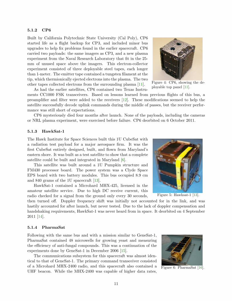
5.1.4 PharmaSat
Figure 6: PharmaSat [16].
Following with the same bus and with a mission similar to GeneSat-1,PharmaSat contained 48 microwells for growing yeast and measuringthe efficiency of anti-fungal compounds. This was a continuation of theexperiments done by GeneSat-1 in December 2006 [15].
The communications subsystem for this spacecraft was almost iden-tical to that of GeneSat-1. The primary command transceiver consistedof a Microhard MHX-2400 radio, and this spacecraft also contained aUHF beacon. While the MHX-2400 was capable of higher data rates,
11

the serial speed between Microhard and the main processor was only 9600 baud, effectively limitingthe maximum over-the-air data rate to less than 9600 baud. The actual over-the-air data rate formost passes was less than 800 bps. The ground segment consisted of an 18-meter dish at SRI In-ternational, and smaller, dual 3-meter dishes at Santa Clara University, where students performedflight operations for PharmaSat.
PharmaSat failed after eight days in orbit, a few passes after the science team declared themission a success. The failure was caused by a miscommunication in the data path between theMicrohard MHX-2400 radio and the main processor on board. A power reset would have clearedthe error, but that capability was not built into the bus [17]. PharmaSat deorbited on 14 August2012.
5.2 ISILaunch 01/PSLV-C14
This was the first launch coordinated by Innovative Solutions in Space (ISIS), a small companybased in Delft, The Netherlands. ISIS was born from the Delfi-C3 project. This PSLV-C14 blastedoff on 23 September 2009 from Sriharikota, India, with Oceansat-2 as the primary payload. Thesatellites went into a 720-km near-circular orbit at 98.2◦.
These CubeSats deployed from four 1U Single Picosatellite Deployers (SPLs), built by Astround Feinwerktechnik Adlershof GmbH in Germany. This spring-loaded system uses permanentmagnets as the actuators [19].
All CubeSats on this launch contained a low-power CW beacon, which made it easy for groundstations to determine which Keplerian elements corresponded to which satellite.
Figure 7: PSLV C14.
5.2.1 BEESAT-1
Figure 8: BeeSat-1 [21].
The first CubeSat built by Technical University of Berlin, BerlinExperimental and Educational Satellite is a technology demonstra-tion mission to test new micro reaction wheels developed at theuniversity. It also contains a small camera.
The main processor is an NXP LPC2292 running at 60 MHz,with 2 MB of RAM and 20 MB of flash memory [20].
BEESAT-1 transmits 4800 or 9600 baud GMSK signals at435.950 MHz. The power output is 500 mW into a monopole an-tenna. It uses a Mobitex packet format, with forward error cor-rection, from a Consumer Microcircuits Limited CMX909B TNC.This satellite is licensed under the amateur satellite service, but itdoes not seem to have been coordinated through the IARU [21].BEESAT-1 is still active over the primary ground station in Berlin.
12

5.2.2 UWE-2
Figure 9: UWE-2 [22].
Built by students at the University of Wuerzburg, the University ofWuerzberg Experimental-2 CubeSat was an evolutionary step fromtheir earlier UWE-1 CubeSat launch on SSETI Express. This 1U’smain experiment was precise attitude determination by combiningand filtering data from the on-board accelerometer, three miniaturegyroscopes, Phoenix GPS receiver, and six sun sensors [22].
The main processor was a Hitachi H8S running uClinux. Thecommunications system was the same as their earlier CubeSat, based around a slightly-modifiedSR-Systems PR430. It transmitted AX.25-formatted data at 1200 baud AFSK on 437.385 MHzwith 1 watt of output power. The antenna was a dipole. UWE-2 ceased functioning in October2009 [23].
5.2.3 ITUpSAT1
Figure 10: ITUpSAT1 [24].
ITUpSAT1 was built by students at Istanbul Technical University.The primary purpose is student education, and the main payloadis a VGA camera based on an OV7620 image sensor. The othersecondary payloads included a three-axis accelerometer, gyro, andmagnetometer.
The satellite is a standard Rev D CubeSat Kit from PumpkinInc., with the MSP430 main processor and Clyde Space EPS withlithium polymer batteries. Attitude is controlled with a passivemagnetic system [24].
The primary transceiver is a Microhard MHX-425, transmitting1 W into a dipole antenna. On the first pass of the satellite overthe university ground station, a link was temporarily establishedwith the MHX-425 radio, but no data was transferred. The Microhard has not been communicatedwith since. The beacon is a BeeLine module, a small 100 mW CW transmitter based on a CC1050single-chip transmitter. Power is boosted to 350 mW via a custom-built amplifier. While thisbeacon was designed for model rockets, it has operated for 3.5 years. The beacon uses a monopoleantenna [25].
5.2.4 SwissCube
Figure 11: SwissCube [26].
SwissCube was built by a consortium of universities in Switzerland,including the Federal Institute of Technology of Lausanne (EPFL).The primary mission of this spacecraft is student education, andthe scientific payload includes a 45 mm telescope for measuringairglow. This spacecraft also contains a three-axis magnetometer,three single-axis gyroscopes, and six novel MEMS sun sensors [26].
The structure was built using a wire electrical discharge machin-ing (EDM) process, which removes all the internal material from asingle block of aluminum, for a total mass of 95 grams [27]. Thepower system was built by students, and directly powers the bea-con board, which transmits a 10 WPM CW signal at 100 mW from an RF Microdevices RF2516modulator and a RF2172 power amplifier. This separate beacon system was done to ensure that
13

even if the rest of the satellite failed, the beacon would still operate and send limited telemetry tothe ground.
The main transmitter operates in the amateur satellite service at 437.505 MHz. The MSP430F1611TNC directly modulates a discrete butler oscillator, and an RF Microdevices RF5110G amplifiesthe signal to slightly less than 1 watt [28]. The modulation scheme is 1200 bps FSK with AX.25packet formatting. Antennas are quarter-wave monopoles for each frequency, with a nichrome burnwire for deployment [29].
For an unknown reason, SwissCube came out of the SPL spinning very fast, around 200◦/sec.Due to an I2C bus error, the team couldn’t turn on the ADCS system. SwissCube was left todetumble by itself until January 2011, when the rate was reduced to 80◦/sec. The team was thenable to command on the power amplifier for an extended period of time, draining the batteries andresetting the satellite. The I2C bus problem cleared itself, and science operations, which beganshortly thereafter, were a complete success [30].
5.3 H-IIA F17
This rocket blasted off on 20 May 2010 with the Akatsuki probe, also known as the Venus ClimateOrbiter (VCO), as the primary payload. After deploying the CubeSats between the first and secondburns of the second stage, the rocket headed toward Venus with the primary satellite and UNITEC-1, a 15-kg satellite from a consortium of 20 Japanese universities. UNITEC-1 used the 5.8 GHzamateur band for communications, but the satellite became silent a few weeks after launch.
These three CubeSats were deployed into a very low 292- x 306-km orbit at 30◦ from two JAXAPicosatellite Deployers (J-PODs), one with Hayato and Negai-Star, and the other with Waseda-SAT2 [31].
Figure 12: H-IIA F17 on the pad.
5.3.1 Hayato
Figure 13: Hayato [32].
Built by Kagoshima University and called K-Sat before launch, themission of this 1U CubeSat was to observe atmospheric moisturecontent to predict heavy localized rains. It also contained a camerafor taking pictures of the earth. The spacecraft was gravity-gradientstabilized with a 60 cm fold-out boom [32].
The main processor was a PIC16F877A running at 4 MHz.Power was supplied by sixteen AAA-sized Ni-MH batteries andtriple-junction solar cells. Attitude determination and control wasprovided by another PIC16F877A with a AMI302 mag sensor.
This satellite used a 100 mW Ku-band 13.275 GHz transmitter in the Earth-exploration satelliteservice with a data rate of 10 kbps or 1 Mbps, depending on the mode [33]. Uplink to Hayato was
14

never achieved, so the satellite was just beaconing housekeeping data at the slower data rate forit’s entire 18 day life. Hayato decayed on 14 July 2010 [34, 35].
5.3.2 Waseda-SAT2
Figure 14: Waseda-SAT2 [36].
Built by students from Waseda University in Japan, this 1U Cube-Sat’s mission investigated whether fold-out solar panels can stabilizethe attitude of the satellite. It also contained an educational op-tical experiment, with LEDs displaying a QR code that containedsatellite telemetry. An on-board camera downlinked pictures of theQR code, as well as general pictures of the earth [36].
The communications system was built around two TXE430-301A transmitter from Nishi Musen Kenkyusyo Co. Both trans-mitted on 437.485MHz, one a 100 mW CW beacon and the othera 150 mW high-speed 9600 baud FSK downlink. This satellite was never heard from in space.Waseda-SAT2 decayed on 12 July 2010 [37].
5.3.3 Negai-Star
Figure 15: Negai-Star [38].
This 1U CubeSat was built by students at Soka University in Japan.Its primary mission was to flight-test a commercial FPGA.
Negai-Star contained two transmitters. The beacon transmitteda 100 mW CW signal at 50 WPM. The data downlink was a 1200baud AFSK transmitter with 400 mW of output power and AX.25framing. Both transmitters were on 437.305 MHz under the ama-teur satellite service, and the UHF downlink antenna was a dipole.This satellite deorbited on 26 June 2010 [38].
5.4 NLS-6/PSLV-C15
The primary vehicle on this mission was Cartosat-2B, a remote sensing satellite built by the IndianSpace Research Organization (ISRO). This launch also contained several secondary satellites, in-cluding AlSat-2A and AISSat-1, a 20-cm nanosatellite that tracks ships via their AIS signals. Thisrocket blasted off on 12 July 2010 into a 630-km circular orbit at 98◦ [39].
The University of Toronto Institute for Aerospace Studies’ Space Flight Laboratory providedlaunch services for AISSat-1 and TIsat-1 through their Nanosatellite Launch Service (NLS-6) pro-gram. TIsat-1 was deployed from a single 1U X-POD. StudSat was released from a deployer builtby ISRO.
Figure 16: PSLV-C15 [39].
15

5.4.1 TIsat-1
Figure 17: TIsat-1 [40].
TIsat-1 is a 1U CubeSat built by the University of Applied Sciencesof Southern Switzerland, with the primary purpose of student ed-ucation. The payload measures atomic oxygen effects on exposedthin bonding wires and nylon wires. It is also designed to be ex-tremely fault-tolerant with three main processors [40].
TIsat-1’s structure was designed and built by students in col-laboration with RUAG Aviation in Lodrino. The power systemwas custom-built and contained both single lithium-ion and singlelithium-polymer batteries. TIsat-1 contains three main processors:one MSP430F169, one PIC18LF8722, and one PIC16.
This 1U CubeSat contains a custom-designed beacon transmit-ter and an Alinco DJ-C6 transceiver transmitting 500 mW. Both radios operate on 437.305 MHz,and use the main satellite processor as the TNC. The CW beacon is based on a CC1010 with aMotorola power amplifier, and transmits 400 mW of power with a symbol rate of 15 WPM, gradu-ally increasing to 180 WPM over a ten-day period. The satellite contains two monopole antennasfor uplink and downlink [41]. TIsat-1 is still operating today.
5.4.2 StudSat
An abbreviation for Student Satellite, this 1U CubeSat was the first satellite built entirely bystudents in a consortium of seven engineering colleges in India. Its primary mission was studenteducation and promotion of space technology in educational institutions. StudSat contained a visi-ble CMOS imager with a ground resolution of 90 meters, and had a mass of around 650 grams [42].
Figure 18: StudSat [42].
The primary microcrontroller on board was an Atmel 32-bitUC3A0512, and the power system was from Clyde Space. Thispower system had a fatal flaw caused by a faulty DC down-converter, and it is theorized that this caused the spacecraft tofail after several days of operation.
The data downlink radio was based on a CC1020 transmitterat 437.505 MHz under an amateur license. The power output wasabout 500 mW, and the data rate was 4800 baud FSK with a customAX.25 protocol with the main processor acting as the TNC. Thesatellite also contained a morse code beacon on 437.860 MHz basedon a MAX1472 crystal-based ASK transmitter chip. It transmitted10 mW at 22 WPM with a two-minute period. Beacons were received by various amateur radiooperators around the world [43].
The satellite contained an orbit propagator that turned on the spacecraft receiver only whenthe satellite was above the primary ground station at the Nitte Meenakshi Institute of Technologyin Bangalore. However, the spacecraft was not put exactly in the orbit that was specified in thepropagator, so the receiver was not active over the primary ground station and no uplink commandswere ever received by the spacecraft [44].
16

5.5 STP-S26
This mission launched on a Minotaur IV rocket on 19 November 2010, from the Kodiak LaunchComplex in Alaska. This rocket did not contain a primary spacecraft, but instead launched fourESPA-class spacecraft and two CubeSats. These microsatellites included STPSat-2, FalconSAT-5,FASTSAT, and FASTRAC. This rocket contained one standard Mk. III P-POD holding RAX-1,and one NASA-modified P-POD containing O/OREOS.
FASTRAC, from the University of Texas (UT) at Austin, won the 3rd University NanosatelliteCompetition in 2004. FASTRAC contained two similar satellites that separated after several weeksand performed thruster, relnav, attitude, and crosslink experiments. It also provided flight heritagefor components that will go into UT’s BEVO-X CubeSat [45, 46]. Using the amateur radio service,these satellites contained several different Hamtronics crystal-controlled transmitters and receiversfor communications, connected to a Kantronics KPC-9612+ TNC [47].
FASTSAT contained several experiments, and also housed another NASA-modified P-POD withNanoSail-D2 loaded inside. FASTSAT was programmed to deploy NanoSail-D2 after one week. Itappeared that the NASA-modified P-POD door did open at the preprogrammed time, but NanoSail-D2 was not ejected because no additional objects were detected by NORAD. It was presumed thatNanoSail-D2 was stuck inside the NASA-modified P-POD. Several weeks later, during a FASTSATorbit maneuver, NanoSail-D2 did successfully deploy, and started transmitting almost immediately.
This was the first CubeSat launch where the Keplerian elements were restricted by NORAD, dueto the sensitive primary payloads. Elements were sent to the individual teams for redistribution.
(a) Launch from Kodiak [51]. (b) RAX-1 P-POD mounted.Figure 19: STP-S26 launch.
5.5.1 RAX-1
The Radio Auroral Explorer (RAX-1) spacecraft was the first satellite funded through the NationalScience Foundation Space Weather program. The primary mission of this spacecraft was to char-acterize field-aligned irregularities of electron density in the auroral region. These irregularitiesdisrupt communication and navigation signals in this region [48].
The ground-based bistatic radar transmited a high-power pulse, around 2 MW EIRP, using alarge phased-array antenna. A radar receiver, built by SRI International, recorded both the directradar pulse and the side scatter. The 1 MHz chunk of recorded spectrum was decimated from 1.2GB to approximately 200 kB for downlink using an onboard Marvell PXA270 processor running at500 MHz.
17

Figure 20: RAX-1 [49].
The communications subsystem consisted of an AstroDevLithium-1 radio at 437.505 MHz, and a Microhard MHX-2400 2.4GHz transceiver. The Lithium radio performed well, operating at9600 baud GMSK and downloading 4.8 MB of commanded data tothe ground. The Microhard radio was never turned on [49].
Since the radar receiver and the primary communicationstransceiver were in the same frequency band, a single quad turnstileantenna was switched between the two radios. The antennas wererestrained for launch using fishing line and 1/8-watt burn resistors.In the center of the turnstile antenna was the 2.4 GHz patch forthe Microhard radio.
Solar cell corrosion, created by improperly stored solar cells, caused RAX-1 to slowly reducefunctionality three months after launch, after one radar experiment was performed. RAX-1 wasdeclared completely non-operational at the end of January 2011, and a failure analysis team de-termined that lack of protection diodes and coverglass on the solar cells were to blame for thepremature failure [50].
5.5.2 O/OREOS
Figure 21: O/OREOS [54].
The Organism/Organic Exposure to Orbital Stresses (O/OREOS)3U CubeSat continues with the common NASA Ames Bus, similarto GeneSat and PharmaSat. It carries two organic payloads anda new deorbit device. The first payload is similar to the earlierGeneSat and PharmaSat payloads, with organisms brought backto life in orbit, and growth rates measured to determine radiationeffects. The second payload exposes the organisms to outer spaceusing an external carousel, and measures cell growth using the sun as a UV source [52].
This satellite uses the same communication system as earlier NASA Ames CubeSats. It uses aMicrohard MHX-2420 as the primary data transceiver, again with limited success. It also containsa Stensat UHF beacon at 437.305 MHz, transmitting 1200 baud AFSK with AX.25 formatting.
Due to the heavy spacecraft mass, a de-orbit device is included. Activated when the P-PODdoor opened, the de-orbit device uses a large spring to extend the end of the spacecraft by 28 cmto increase the satellite’s surface area [53]. O/OREOS completed all of its science missions in May2012, and has downloaded a total of 8 MB via the Microhard radio [54].
5.5.3 NanoSail-D2
Figure 22: NanoSail-D2 with saildeployed [56].
While the first NanoSail-D spacecraft was lost in the Falcon 1 launchfailure from the Kwajalein Atoll in August 2008, this second 3Uflight model successfully achieved orbit after a delayed ejection fromFASTSAT on 17 January 2011. The primary mission included suc-cessfully deploying the 10-square-meter sail on orbit, showing thatthe solar sail concept can de-orbit a small spacecraft [55].
This spacecraft was built using the common 1U NASA Amesbus, very similar to GeneSat and PharmaSat, and a 2U solar sailunit, built by ManTech SRS and Marshall Space Flight Center.There were no solar panels on this satellite. NanoSail-D2 contained a Stensat beacon operating at437.270 MHz and a Microhard MHX-2400 transceiver. The solar sail deployed as planned on 20
18

January 2011 at an altitude of 640-km, and the satellite deorbited 240 days later on 17 September2011 [56, 57].
5.6 Falcon 9-002
This was the first CubeSat launch from Kennedy Space Center in Florida, and the first launch ofCubeSats from a SpaceX rocket. This launch contained six Mk. III P-PODs, mounted to the trunksection, which deployed after the Dragon Capsule separated. This was the second Falcon 9 launchunder the NASA Commercial Transportation to Space (COTS) program, and the purpose of thislaunch was a re-entry test of the Dragon Capsule. The eight satellites were deployed in a 300-kmcircular orbit, and all have deorbited.
SRI International and Cal Poly performed integration services for this launch. This rocketblasted off on 8 December 2010. All P-PODs deployed successfully, and the Dragon Capsulesuccessfully returned to earth [58].
(a) P-PODs mounted to trunk. (b) Dragon pulling away. Three P-PODs can be seen asdark objects at the top and right sides of the image.
Figure 23: Falcon 9 [58].
5.6.1 Perseus (4)
Figure 24: Perseus [60].
The mission of the four 1.5U CubeSats from Los Alamos NationalLab was to demonstrate the ability to rapidly build a small satel-lite, gain CubeSat build and operations experience, and prove thatCOTS components can survive the space environment. These foursatellites were built at in under six months [59].
The communications system was based around a single-chiptransceiver into a dipole antenna. Successful tests of the commu-nication system included two- and three-way communication andcollection of telemetry.
5.6.2 QbX (2)
These two identical 3U spacecraft were the first in the Colony series of spacecraft, bought by theNational Reconnaissance Office (NRO) from Pumpkin Inc. The main purpose was to explore thesuitability of small spacecraft for experimentation and technology development. The payload wasa communications experiment [61].
19

The Colony 1 Pumpkin bus is a standard 3U CubeSat Kit with extra modifications, includingan IMI-100 ADACS unit, deployable solar panels, and a pluggable processor module architecture.The power system was a Clyde Space EPS unit, modified to remove several phantom-dischargeflaws found in the standard COTS unit. The flight processor was a SiLabs C8051F120.
Figure 25: Colony I bus [62].
Each spacecraft contained two radios. The tracking, telemetry,and command (TTC) radio was a custom design at 450 MHz witha data rate of 9600 baud GMSK and 1 watt of output power. Boththe TTC and payload radio fed a single nadir-pointing, deployablequadrafilar helix antenna. The TTC radio performed well, but thepayload radio had issues that were never solved, and success waslimited. The ground segment consisted of the first version of theMobile CubeSat Command and Control (MC3) system, developed by NRL [62].
5.6.3 SMDC-ONE
Figure 26: SMDC-ONE engi-neering model [65].
The Space and Missile Defense Command Operational Nanosatel-lite Effect (SMDC-ONE) 3U satellite was built by Miltec for SMDCas a rapid-development spacecraft. This was the first Army-builtspacecraft in over 50 years, and signaled the Army’s return tospace [63].
It was powered by the standard COTS power system from ClydeSpace. The communications subsystem was built by Pericle Com-munications of Colorado Springs, and contained a quad turnstileantenna on each end of the spacecraft, one for receive and one fortransmit [64].
The spacecraft was designed to relay short messages from unat-tended ground sensors, and send short messages between estab-lished ground stations in Huntsville, Ala., and Colorado Springs,Colorado. It successfully completed the mission before deorbitingafter about 35 days. Students from nearby universities performedoperations on this satellite [66].
5.6.4 Mayflower
The Mayflower/Caerus 3U CubeSat was a collaboration between Northrop Grumman, who builtthe propulsion and power payload, and the Space Research Engineering Center at the Universityof Southern California, who integrated the payload into a Pumpkin 1U kit. The satellite alsocontained a high-power fold-out solar array, rated at 48 watts [67].
Figure 27: Mayflower [68].
Mayflower’s primary communication system consisted of a Mi-crohard MHX-425 at 437.000 MHz. Mayflower also contained a 1watt Stensat Radio Beacon, with a data rate of 1200 baud AFSKat 437.600 MHz [68]. Both radios shared a turnstile antenna, po-sitioned between the 1U bus and 2U payload. The team appliedfor an experimental license for the Microhard and an amateur li-cense with IARU coordination for the Stensat beacon, but neitherlicensing process was completed before launch.
Strong UHF downlink beacons were heard from the satellite for one day only. It is theorized thatthe attitude control system was not strong enough to point the solar cells at the sun, causing the
20

satellite to lose power. No uplink commands were ever received by the spacecraft. The propulsionpayload was never exercised. Due to the low orbit and fold-out solar panels, Mayflower deorbitedon 22 December 2010, only 14 days after launch [69].
5.7 ELaNa-1/Taurus XL
This launch was the first in the Educational Launch of Nanosatellites (ELaNa) missions, managedby the Launch Services Program at Kennedy Space Center. This program was started by GarretSkrobot in 2010 as a way to get student’s spacecraft into orbit.
This Taurus XL launch from Vandenberg Air Force Base in California contained the Glorysatellite as the primary, a 545-kg satellite whose mission included measuring total solar irradianceand taking pictures of clouds. It was the first launch of a Taurus XL since the Orbiting CarbonObservatory satellite failed to achieve orbit in February 2009 after the fairing failed to separate [70].
Inside a single Mk. III P-POD mounted next to the upper-stage motor were three 1U satellitesfrom a consortium of universities in Kentucky, the University of Colorado at Boulder, and MontanaState University:
� KySat-1 was the first satellite from Kentucky Space, a consortium of universities and com-panies in Kentucky. Its primary mission was K-12 outreach, and it used a Stensat digitaltransponder so that students could send messages through the spacecraft. It also containeda Microhard MHX-2400 transceiver [71].
� Hermes was the first CubeSat built by the Colorado Space Grant Consortium at the Univer-sity of Colorado, Boulder. This 1U’s primary mission included flight testing of a high-speedS-band radio based on the Microhard MHX-2400, and development of a spacecraft bus. Thecommunications subsystem was built around a Yeasu VX-7R transceiver operating under theamateur radio service at 437.425 MHz with 1 W output power into a dipole antenna [72].
� Explorer-1’ from Montana State University measured the radiation belts around the earth,using a Geiger tube. The satellite contained a CC1000 radio transceiver at 437.305 MHz with850 mW of output power into a dipole antenna. The second flight unit was flown in October2011 [73].
This launch failed to achieve orbit on 4 March 2011 after the fairing failed to separate, the sameproblem the previous Taurus XL launch had. All of the satellites are now in the South Pacificocean. While this first launch of the ELaNa program was not a success, the other ELaNa launcheswill use different rockets, increasing the chance of success for the overall program.
Figure 28: P-POD being mounted to the aft end of the Taurus XL [74].
21

5.8 PSLV-C18
This rocket blasted off on 12 October 2011 from the Satish Dhawan Space Center in Sriharikota,India. The primary satellite is the Megha-Tropiques satellite, which measures the water cycle inthe tropics. The other secondary satellites were SRMSat and VesselSat-1, a satellite AIS receiver.All four satellites on this launch were delivered into a 860-km circular orbit at 20◦. The single1U CubeSat was deployed by a custom system built by the Indian Institute of Technology (IIT)Kanpur, with help from ISRO [75].
Figure 29: IIT Kanpur Deployer system on the upper stage.
5.8.1 Jugnu
Figure 30: Jugnu [76].
This 3U CubeSat was designed and built entirely in India by stu-dents at IIT Kanpur, under the guidance of ISRO engineers. Itsprimary goal was education and development of procedures and in-frastructure related to small satellite development. The primarypayload included an IR camera, GPS receiver, custom-built reac-tion wheels, and an Analog Devices COTS inertial measurementunit [76, 77].
The satellite was built around a 3U Pumpkin structure, with aPumpkin MSP430 and AT91SAM7 ARM 7 processor, and custombuilt power system. The communication subsystem contained threeradios. The command receiver was a custom design based on anAnalog Devices ADF7020-1. The CW beacon transmitter at 437.275 MHz was also a customdesign, based on a MAX1472 crystal-based transmitter, and outputted 10 mW of power. The 2400baud FSK transmitter at 437.505 MHz was a custom design based on the Chipcon CC1070 with aRF5110G power amplifier for 1 watt output power [78]. All radios were amateur-licensed and usedseparate monopole antennas that deployed from the center of the spacecraft.
5.9 ELaNa-3/NPP
This Delta II blasted off from Vandenberg Air Force Base on 28 October 2011 into a 800- by 400-kmorbit at 97◦ [79]. The primary payload was the NPOESS Prepatory Project (NPP), a precursor tothe next generation of military weather satellites, and three Mk. III P-PODs from Cal Poly housedsix satellites. This was the first successful launch of the ELaNa Program.
After P-POD deployment, NORAD was able to track only five objects, and it appears that M-cubed and HRBE are in close proximity or attached to each other. While the reason is unknown, the
22

M-cubed team believes that the satellites are stuck together due to the permanent magnets [80, 81].The HRBE team is not convinced [87].
(a) NPP, with the P-PODs mounted in thelower right.
(b) AubieSat-1, HRBE, and M-Cubed before integration.
Figure 31: ELaNa-3/NPP launch [79].
5.9.1 AubieSat-1
AubieSat-1 was the first CubeSat from Auburn University. Its primary mission was education, andcontained a science experiment testing new protective plastic films installed over the solar cells.
Figure 32: AubieSat-1 [83].
AubieSat-1’s 1U structure was built by students, and containedan Atmel ATmega1281 as the main microprocessor. The custom-built power subsystem used an Atmel XMega128A1 for maximumpeak-power tracking and charge control of the lithium-ion batteries.
The transmitter was based on a Melexis TH72011 as the ex-citer, with a NEC discrete power amplifier that transmited about800 mW on 437.475 MHz under the amateur satellite service. Themodulation scheme was 20 WPM CW. The spacecraft receiver useda Melexis TH71102 single-chip IC with a NEC UPC3227TK low-noise amplifier [82].
AubieSat-1’s downlink CW was strong enough to decode, butuplink commands were not received by the spacecraft after launch. The team theorized that theseparate Nitinol ‘memory wire’ uplink and downlink dipole antennas did not deploy. The teamtraveled to Montana State University to test this theory on MSU’s 1.5 kW amplifier, originallypurchased for HRBE, and a link was established to the spacecraft [83].
5.9.2 DICE (2) *
The Dynamic Ionosphere CubeSat Experiment (DICE) consists of two 1.5U CubeSats from theSpace Dynamics Laboratory at Utah State University. These identical satellites contain a langmuirprobe for electron density measurements, several electric field probes, and a magnetometer. Thisis the second mission launched for the NSF CubeSat Program [84].
Each DICE satellite contains a Cadet radio from L3 Communications. It operates at 465 MHzin the Meteorological-satellite band. Due to severe power flux density restrictions placed on this
23

band, the transmitter power is about 1 watt, spread out over the 3 MHz BPSK signal. This powerrestriction requires a big dish to receive the signals; 18-m dishes at both NASA Wallops and SRIInternational were used. Local narrow-band interference prevented the dish at SRI Internationalfrom decoding much data. After the forward error correction, the bit rate is 2.6 Mbps. The totaldata downloaded as of April 2013 is 8.4 GB of data for both satellites [85].
Figure 33: Two DICE spacecraftwith stands [84].
Both DICE and CINEMA (launched on ELaNa-6, see Section5.11.7) were licensed by the NSF Spectrum Committee throughthe NTIA, which authorizes US-Government-funded and -operatedsatellites. After this process was complete, the NTIA stated thatthese types of NSF-funded but contractor-operated missions shouldbe licensed through the FCC, either experimentally or through theappropriate service. NSF teams should get experimentally licensedin the future [5].
5.9.3 HRBE
Originally named Explorer 1 Prime Flight Unit 2, the Hiscock Radiation Belt Explorer (HRBE) isthe first CubeSat from the Space Science and Engineering Laboratory at Montana State Universityto achieve orbit. Their earlier MEROPE and Explorer 1 Prime satellites failed to reach orbit on theearlier Dnepr-1 and ELaNa-1/Taurus XL rocket failures. The primary mission is student educationand process development, with a secondary science mission measuring the Earth’s radiation beltusing a Geiger tube [86].
Figure 34: HRBE [87].
HRBE’s communication system is based on a ChipCon CC100radio at 437.505 MHz, outputting 850 mW into a monopole an-tenna. The packet format is standard AX.25 1200 baud FSK. Asdemonstrated by CP2 and CP6, the CC1000 receiver is quite deaf,and for the first few months, no uplink commands were received.After traveling to SRI International’s 60-ft dish, the team provedthat a link deficiency was the only problem, and purchased a 1kW amplifier for their ground station. Regular contacts with thespacecraft were initiated [87].
Unfortunately, HRBE completely reboots itself from read-onlymemory every 24 hours. Therefore, any change in configuration tothe satellite, including beacon rate, science detector thresholds, and high-voltage settings, are resetto the defaults every day. This makes getting real science from the spacecraft challenging. InSeptember 2012, the satellite began losing power, could no longer keep itself alive through eclipses,and sometimes browned out after transmitting a packet [88]. This indicated that its batteries werefailing, but by November the problem had rectified itself and the satellite was back to normaloperations [89].
24

5.9.4 M-Cubed
Figure 35: M-Cubed [91].
A collaboration between the NASA Jet Propulsion Laboratory andthe University of Michigan, the Michigan Multipurpose Minisat’s1U payload was to flight test and qualify a Virtex-5QV FPGA forJPL. A small 1600x1200-pixel OmniVision 2655 CMOS imager gen-erated data for the FPGA [90].
The main processor on M-Cubed was a Stamp9G20. The powerand structure subsystems were designed by students at the Univer-sity of Michigan.
The spacecraft used two AstoDev Lithium-1 radios, one for up-link and the other for downlink. The amateur-licensed downlink of1 watt transmitted 9600 baud FSK at 437.485 MHz. The antennasconsisted of two monopoles. Beacons were very weak to decode, sovery few packets were decoded and sent in by hams around the world [91]. The team traveledto SRI International’s 60-ft dish to try to uplink commands and decode more telemetry from thespacecraft, but the effort was not successful.
5.9.5 RAX-2
Figure 36: RAX-2 [49].
This satellite is the flight backup of the earlier RAX-1 CubeSat thatlaunched on STP-S26 in November 2010. RAX-2 was built to cor-rect the RAX-1 solar panel failure and continue the RAX mission.It’s subsystems are composed of a combination of RAX-1 backuphardware and new components. RAX-2’s science mission is a com-plete success, and it has seen numerous field-aligned irregularitiesover the course of its 32 experiments [92, 93].
The communications system is an AstroDev Lithium-1 radio at437.345 MHz 9600 baud GMSK, the same as RAX-1 [94]. It hasdownlinked 242 MB of science and telemetry data. The Microhard2.4 GHz transceiver was exercised in orbit, but the team realizedthat the very low effective data rate of this radio–around 10 kbps–and high current draw meansthat this radio is a more effective heater than transceiver.
5.10 Vega VV01
Originally scheduled for 2008, the maiden flight of the Italian-built VEGA rocket lifted off on 13February 2012 from Kourou, French Guiana. Since this was the first launch of this rocket, therewas no primary payload. The main secondary satellites were LARES, a laser relativity satellite,and ALMASat-1, a technology demonstration microsatellite from the University of Bologna.
This rocket contained three Cal Poly-built Mk. III P-PODs for the seven 1U spacecraft. Dueto CubeSat design and fabrication issues and delays with the rocket, the other two slots wereabandoned, and mass models were wired onto the P-POD pusher plate. SwissCube found anearlier launch, and HiNCube will be on a commercial launch in the near future. The rocket placedthe CubeSats into a 308- x 1427-km orbit at 69.5◦.
25

Figure 37: Xatcobeo, e-st@r, and Goliat CubeSats with their integration teams.
5.10.1 Xatcobeo
Figure 38: Xat-cobeo [95].
This 1U CubeSat was built by students at the University of Vigo, in collab-oration with the Spain National Institute for Aerospace Technology (INTA).The primary purpose is student education, with three payloads including anFPGA-based software-defined radio, a non-ionizing radiation dosimeter, anda new solar panel deployment mechanism [95].
The power system for Xatcobeo is from Clyde Space, with two deployablesolar panels in addition to the body-mounted panels. The main processoris a Vertex-II FPGA [96]. The communications system is a U482C fromGomSpace, transmitting 1200 baud MSK at 437.365 MHz in the amateur radio service. It alsocontains a CW beacon at 20 WPM with housekeeping data. The radio transmits into a custom-designed turnstile antenna [97].
5.10.2 ROBUSTA
Figure 39: RO-BUSTA [100].
The Radiation On Bipolar for University Satellite Test Application (RO-BUSTA) CubeSat was built by students at the University of Montpellier 2 inFrance. The main mission of this 1U CubeSat was student education, and theprimary payload was a radiation test of two integrated circuits, including theradiation-sensitive LM139 voltage comparator and LM124 voltage amplifier.
The structure was custom-built by students at the university, and themain processor was a PIC18F4580 running at 4 MHz. The power systemwas custom-built and includes triple-junction solar cells from Azurspace anda single lithium-ion battery.
ROBUSTA’s transmitter was based on a MC12181 synthesizer and MAX2608 VCO. It transmit-ted 800 mW at 437.325 MHz in the amateur satellite service. The data rate was 1200 baud AFSKwith a AX.25 format. The beacon period was three minutes, and the antenna was a dipole [98].
A power system defect prevented the batteries from charging. Faint signals were heard afterlaunch, but no telemetry was decoded. Reset commands were received by the spacecraft, but thesatellite died when the batteries lost their charge [99, 100].
5.10.3 e-st@r
Built by the Politecnico di Torino in Turin, Italy, this 1U CubeSat’s main mission was studenteducation, and the development and testing of an attitude determination and control system [101].
26

This university’s previous small satellite PiCPoT was a 13-cm cube that flew on the failed Dnepr-1mission in July 2006 [102].
Figure 40: e-st@r[105].
The main processor and structure was CTOS unit from Pumpkin, andthe power system was from Clyde Space [103].
e-st@r used a commercial Radiometrix BHX2-437-5 transceiver out-putting 500 mW, connected to a PIC16F that acted as the TNC. The satellitetransmitted in the amateur satellite service at 437.445 MHz with a 1200 baudAFSK modulation scheme and AX.25 formatting. Packets were received byground stations across Europe, but no data was decoded. It appeared thatthere was a power problem , as the signal kept getting weaker before thesatellite failed a few weeks after launch [104, 105].
5.10.4 Goliat
Figure 41: Goliat[107].
This 1U CubeSat was primarily built by the University of Bucharest under thesupervision of the Romanian Space Agency. Smaller groups at other universi-ties also helped. As was the case for all CubeSats on this first VEGA launch,Goliat’s primary objective was student education. Its science payloads in-cluded a radiation detector, a micro-meteoroid detector, and a narrow-angle3 megapixel optical imager with a 57-mm focal length [106].
The on-board computer consisted of several MSP430 with a 2 GB SDcard, and the power system was designed by students. The structure wasa COTS unit built by Pumpkin. This spacecraft transmitted 500 mW with an Alinco DJ-C7transceiver and FX614 TNC under the amateur satellite service on 437.485 MHz, with 1200 baudAFSK modulation scheme and AX.25 formatting. This radio also transmitted a CW beacon at 20WPM [107]. The UHF antenna was deployed with a small motor. This satellite also contained aMicrohard MHX-2420 transceiver with a quarter-wave monopole antenna, although a link was notestablished with this radio during the satellite’s limited 1 week lifetime [108, 109].
5.10.5 PW-Sat
Figure 42: PW-Sat[111].
Built by students at the Warsaw University of Technology (WUT) and incollaboration with Space Research Center of the Polish Academy of Sciences,this 1U CubeSat’s mission was orbital debris mitigation. The primary payloadcontained a 1.2-meter deployable tail, with solar cells along the side, intendedto reduce the orbit lifetime by one-third of a year [110].
The structure of this spacecraft was built by students at WUT. The mainprocessor consisted of an ARM7 NanoMind A702 module from GomSpace.
The single ISIS TRXUV transceiver had two modes, and transmitted 200 mW on 145.900 MHzwith an amateur license. The CW mode transmitted basic telemetry information and messagesfrom the team at 12 WPM. The high-speed downlink mode transmitted a 1200 baud BPSK signalwith AX.25 formatting [111]. Due to uplink communication and power difficulties, the tail was notdeployed. PW-Sat ceased functioning on 23 Dec 2012.
5.10.6 Masat-1
Masat-1 is the first CubeSat from the Budapest University of Technology and Economics in Hun-gary. Its main mission is student education, and to create processes and procedures for their nextCubeSat. The main payload is a visible camera, with a 640x480 pixel image area and a ground
27

resolution of 2- to 10-km, depending on actual altitude. The team has taken many pictures of theEarth, including several mosaic and anaglyph 3D [112].
Figure 43: Masat-1[114].
The main processor of Masat-1 is a dsPIC33F, which also acts as theTNC. The custom power system uses PIC12 microcontrollers for peak powertracking.
The satellite uses a Si4432 single-chip transceiver at 437.345 MHz, with anexternal power amplifier and LNA. Within a one-minute period, it transmitsa 100 or 400 mW CW signal with the callsign and limited telemetry, thenswitches to a 625, 1250, or 5000 bps GFSK signal for higher-speed transmis-sion [113]. The GFSK signal is FEC-encoded with a binary Golay code, and the team providesclient software for beacon decoding and submission, as well as a smartphone application for pictureviewing [114]. A USB dongle receiver was also developed [115].
5.10.7 UniCubeSat-GG
Figure 44:UniCubeSat-GG[116].
The 1U UniCubeSat-GG satellite was the first CubeSat built by the SapienzaUniversity of Rome. Its primary purpose was student education, and the pay-load consisted of a two-element gravity gradient boom stabilization system.Solar panels were installed on the boom, and the distance between the tipmasses was approximately 90 cm. Students built a custom structure, andthe power system was a Clyde Space EPS board with Spectrolab TASC cells.The main processor was an MSP430 [116].
This spacecraft had a custom AstroDev transceiver and transmitted on437.305 MHz under an amateur radio license. The data rate was 9600 baudGFSK with AX.25 formatting and 500 mW output [117, 118]. It also contained a CW beacon.Faint signals were heard from this CubeSat in the two days after launch, but it is theorized thatthe power system failed after several days and the spacecraft went silent [119].
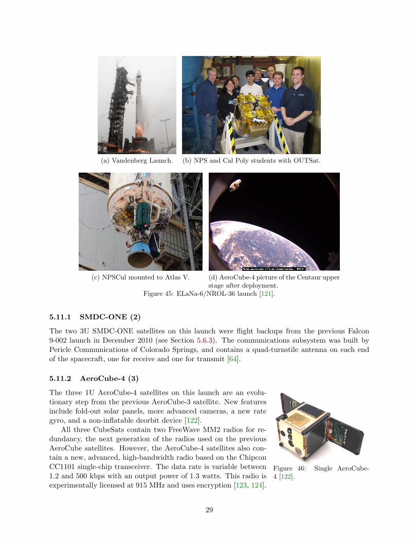
5.11 ELaNa-6/NROL-36
This was the first launch of CubeSats from an Atlas V from Vandenberg Air Force Base, California.The primary spacecraft was classified, so the same ephemeris restrictions were present as on theprevious STP-S26 launch from Kodiak, Alaska (see Section 5.5). The NRO and NASA workedtogether for this launch, with NRO manifesting five of the eight P-PODs, and NASA’s ELaNaprogram filling the other three.
This was the first flight of the Naval Postgraduate School CubeSat Launcher (NPSCuL). Just afive-sided box, the NPSCuL housed eight regular Mk. III P-PODs. Cal Poly and SRI Internationalprovided integration services. The integrated NPSCuL with CubeSats was called OUTSat; it wasmounted on the Aft Bulkhead Carrier (ABC) of the Atlas V launch vehicle [120]. This rocket waslaunched on 13 September 2012, and the CubeSats were deployed into a 770- x 480-km orbit withan inclination of 64◦.
28
(a) Vandenberg Launch. (b) NPS and Cal Poly students with OUTSat.
(c) NPSCul mounted to Atlas V. (d) AeroCube-4 picture of the Centaur upperstage after deployment.
Figure 45: ELaNa-6/NROL-36 launch [121].
5.11.1 SMDC-ONE (2)
The two 3U SMDC-ONE satellites on this launch were flight backups from the previous Falcon9-002 launch in December 2010 (see Section 5.6.3). The communications subsystem was built byPericle Communications of Colorado Springs, and contains a quad-turnstile antenna on each endof the spacecraft, one for receive and one for transmit [64].
5.11.2 AeroCube-4 (3)
Figure 46: Single AeroCube-4 [122].
The three 1U AeroCube-4 satellites on this launch are an evolu-tionary step from the previous AeroCube-3 satellite. New featuresinclude fold-out solar panels, more advanced cameras, a new rategyro, and a non-inflatable deorbit device [122].
All three CubeSats contain two FreeWave MM2 radios for re-dundancy, the next generation of the radios used on the previousAeroCube satellites. However, the AeroCube-4 satellites also con-tain a new, advanced, high-bandwidth radio based on the ChipconCC1101 single-chip transceiver. The data rate is variable between1.2 and 500 kbps with an output power of 1.3 watts. This radio isexperimentally licensed at 915 MHz and uses encryption [123, 124].
29

5.11.3 Aeneas
Aeneas is a 3U CubeSat built by the Space Research Engineering Center at the University ofSouthern California. The main mission is tracking cargo shipping containers as they cross theocean. The satellite listens for existing S-band transmitters on containers that communicate withinshipping ports. The satellite is based on their earlier Mayflower satellite with a Pumpkin Colony Ibus [125].
Figure 47: Aeneas deployable S-band dish [126].
The primary mission requires a 0.5-m deployable S-band dish,which occupies 1.5U of this spacecraft. Once a link to the ship-ping containers on the open ocean is closed and identification datatransferred, accurate attitude knowledge is used to geolocate thecontainer on the surface of the earth [126].
This satellite uses an experimentally licensed Microhard MHX-425 transceiver at 437.0 MHz for its primary communications,exactly the same radio used on their previous Mayflower Cube-Sat [127]. As documented with HawkSat-1, their previous missionMayflower, the NASA Ames CubeSats, and RAX satellites, the Microhard is not designed for spaceand performs poorly. The team traveled to SRI International’s 60-ft dish to see if a bigger dishwould help close the link, but the results were inconclusive.
The satellite also contains a 1 watt Stensat radio beacon at 437.600 MHz, with a data rate of1200 baud AFSK, licensed under the amateur satellite service. The antennas for both the Microhardtransceiver and Stensat transmitter are monopoles on the end of the 3U fold-out side panels [69].
5.11.4 CSSWE
Figure 48: CSSWE [129].
The 3U Colorado Student Space Weather Experiment (CSSWE)CubeSat was the sixth NSF-funded CubeSat project, and third tobe launched. The primary science mission is to measure the energet-ics of solar-produced relativistic electrons and protons during solarflares, and to study how they impact the Earth’s outer radiationbelts. The secondary mission is student education [128, 129].
This spacecraft uses the standard Pumpkin CubeSat KitMSP430F2618 main processor, solid Pumpkin structure, and a custom-built power system withoutpeak power tracking. A passive magnetic system is used for attitude control [130].
CSSWE uses an AstroDev Lithium-1 radio on the spacecraft, transmitting on 437.345 MHzat 9600 baud GMSK with an experimental license. The monopole antenna protrudes one end ofthe spacecraft. The ground station at the University of Colorado uses a Kenwood TS-2000, andcommunications have worked well [131].
5.11.5 CP5
Figure 49: CP5 [132].
This 1U satellite built by Cal Poly was their fourth satellite to suc-cessfully reach orbit. Its primary purpose was student education, andthe main payload was a solar sail deployment experiment. Studentswere to measure the drag of the 0.5-square-meter sail via orbit decayand optically measure the degradation of the sail in orbit.
As was the case for the previous CP-series of satellites, the mainprocessor was a PIC18LF6720, the structure was designed and builtby students, and the power system was custom built without peak
30

power tracking. The communications system was based on one CC1000 single-chip transceiver,with the same PIC processors for the TNC. CP5 transmitted 500 mW at 437.405 MHz into adipole antenna. This transceiver performed poorly, with typically one uplink command received bythe satellite per pass. Downlink was more reliable, with several beacons decoding per pass.
Cal Poly attempted to deploy the sail, but lost contact with CP5 shortly thereafter. No changein altitude was noticed in the data. The last beacon was heard in January 2013 [132].
5.11.6 CXBN
Figure 50: CXBN [133].
Primarily built by students at Morehead State University (MSU) inKentucky, this 2U CubeSat’s primary mission is student educationand the starting of a space program at MSU. The primary payloadis a cadmium zinc telluride detector array that measures the cosmicX-ray background radiation in the 30-50 kEv range. Other smallerpayloads include a COTS MEMS gyro and a novel star sensor [133].
The main processor is a 25 MHz MSP430, and the power sys-tem is a custom in-house design with four lithium-ion 18650 cellsfor energy storage. The structure was custom built at MSU, andholds four deployable solar panels. The entire spacecraft is spin-stabilized.
The communications subsystem is built around an AstroDev Lithium-1 radio, transmitting 9600baud GFSK at 437.525 MHz with 1.5 watts of power in the amateur satellite service. The antennais a turnstile [134]. Communications with CXBN were spotty from the beginning. For an unknownreason, the beacon was very weak, and few stations copied telemetry. Command uplink was alsodifficult. MSU owns and operates a 21-meter dish nearby, but UHF feeds are not installed [135].
5.11.7 CINEMA
CINEMA is UC Berkeley’s first CubeSat, and its STEIN instrument will measure energetic ions,electrons, and neutrals at high ecliptic latitudes. This project is funded by the NSF’s CubeSatprogram, under the direction of Therese Jorgensen [136]. Kyung Hee University in South Koreais building two more replica satellites for higher-precision measurements. These CubeSats will belaunched on a Dnepr rocket in the middle of 2013 [137].
Figure 51: CINEMA [139].
The main processor of CINEMA is a Pumpkin CubeSat Kitwith pluggable dsPIC33FJ256 module [138]. The structure wasbuilt by students, and the power system is a Clyde Space EPSmodule. The instrument interface board contains an Actel IglooFPGA, and controls the S-band radio, STEIN science instrument,and magnetometer developed by Imperial College in London.
The downlink transmitter of CINEMA is an Emhiser EDTC-01DEA running at 1 MBit/sec FSK. It’s licensed through the NTIAin the 2200-2290 MHz Space Research band. It is the second Cube-Sat licensed for this band, after CanX-2 in 2008. However, the Igloo FPGA can’t transfer datafrom the SD card to the radio very quickly, so half of the downlink data is stuffing frames, reducingthe effective throughput to 0.5 MBit/sec [139].
UC Berkeley uses an existing 11-m dish for their ground station receiver. This dish also commu-nicates with their other small satellites, so downlinks must be scheduled. This 2.2 GHz downlinksystem performed well [140]. However, there are some issues with the uplink receiver or antenna
31

system on the spacecraft, and limited commands have been received by the satellite. The teamtraveled to SRI International’s 60-ft dish to help close the link, but results were mixed due to otherissues on the spacecraft.
5.11.8 Re
Re is a 3U telescope looking for near-Earth space debris. The payload was built by LawrenceLivermore National Laboratory and integrated by the Naval Postgraduate School (NPS) into a 3UColony II bus, built by Boeing and funded under the Colony program at the NRO. This satellite isone-half of the Space-Based Telescopes for Actionable Refinement of Ephemeris (STARE) project.The other CubeSat was manifested on this launch, but wheel problems with the bus prevented itsintegration into the NPSCul [141, 142].
Figure 52: Re flight model [143].
This is the first launch of the Colony II bus. The communi-cations system of this bus is based around a modified AstroDevHelium He-100 radio. Downlink is at 915 MHz FSK, with a datarate of 57.6 kbps and AX.25 packet formatting.
The spacecraft downlink is provided through the Mobile Cube-Sat Command and Control (MC3) system, a ground station net-work being jointly developed by the Naval Research Lab and NPS.It is based on COTS hardware, and includes Icom IC-9100 radios,Yaesu G-5500 rotators, and a GDP Space Systems 4425D software-defined receiver. The “mobile” specification implies that the 1/2 rack of radios and computers canbe shipped anywhere in the world and installed within as little time as a single day [144].
Re launched with mis-configured software, so its solar panels and antenna did not deploy auto-matically. It is unclear whether the single uncovered solar panel can provide enough power to keepthe bus alive or burn the nichrome wires on the deployables. NPS traveled to SRI International’s60-ft dish to send commands to deploy the antenna and solar panels, but it’s unclear whether theeffort succeeded [145].
32

6 Conclusion
Tables 1 and 2 show that many of the university-class CubeSats are still using slower data rates.This is likely due to the ease at which hardware can be acquired. However, for some of the missionsthat require higher data rates, teams have taken the leap and purchased radios specifically designedfor high-speed satellite communications. Success has been mixed, although that may be becausethe CubeSats with higher data rates are the first to have been built by their teams, and not allproblems can be traced to communications.
Most first CubeSats, whether built by a university or by an organization with prior satelliteexperience, have limited success. Recent examples include Re, CINEMA, CXBN. RAX is a typicalexample, the first one failed after a few months but the second is performing well after 18 monthsin orbit. Teams should view their first CubeSat as a demonstration mission to work out all thebugs, and progress to science payloads with subsequent satellites.
Many people are interested only in the spacecraft’s payload, as that is what funding is providedfor. However, no matter how much money or time is spent on the payload, if the structure is poorlydesigned, the vibe test will not succeed; and if the communications or power systems don’t work,then the satellite’s payload won’t work in space.
Uplink still also seems to be problematic. Of the 49 CubeSats discussed in this paper, only twowere dead on arrival and never heard from in space. Of the remaining 47 CubeSats, seven neverreceived any ground commands and did not perform their primary mission. With comparativelyunlimited transmit power and antenna gain available for the uplink, the satellite should clearlyhear the ground station. Teams should extensively test their command receiver before launch.
* The following applies to DICE (Section 5.9.2) only: This material is based upon work sup-ported by Utah State University Research Foundation under Award No. CP0024199. Any opinions,findings, and conclusions or recommendations expressed in this publication are those of the authorsand do not necessarily reflect the views of Utah State University Research Foundation.
33

References
[1] Bryan Klofas, Jason Anderson, and Kyle Leveque. “A Survey of CubeSat Communication Systems.”In Proceedings of the 5th Annual CubeSat Developers Workshop. San Luis Obispo, California. April2008.
[2] Cliff Buttschardt and Clark Savage Turner. “Making a Case for Amateur Spectrum through Research,Education and Industry Cooperation.” In Proceedings of the 20th AMSAT Space Symposium. FortWorth, Texas. November 2002.
[3] Bryan Klofas. “Amateur Radio and the CubeSat Community.” In Proceedings of the 24th AMSATSpace Symposium. San Francisco, California. October 2006.
[4] Sankar Persaud. “Regulatory matters concerning authorization of Small Sats: Some CommonMisunderstandings about the FCC and Licensing.” Presented at the 9th Annual CubeSat SummerWorkshop. Logan, Utah. August 2012.
[5] Tomas Gergely and Andrew Clegg. “CubeSat Issues: Where Are We?” Presented at the CubeSatHigh-Speed Downlink Communications meeting, held during the 9th Annual CubeSat DevelopersWorkshop. San Luis Obispo, California. April 2012.
Minotaur 1
[6] “CubeSats.” NASA Wallops Press Release. Available athttp://www.nasa.gov/centers/wallops/pdf/326337main Cubesat%20backgrounder.pdf. Accessed 3April 2013.
[7] David Hinkley. “AeroCube 3 and AeroCube 4.” Presented at the 2012 Summer CubeSat Workshop.Logan, Utah. August 2012.
[8] AeroCube-3 experimental license. 0018-EX-ST-2008.
[9] David Hinkley. Personal Communication. 18 February 2011.
[10] Petras Karuza and David Hinkley. “Solar Cell Installation Using Double Sided Polysiloxane PressureSensitive Adhesive (PSA) Polyimide Film.” Presented at the 6th Annual CubeSat Summer Workshop.Logan, Utah. August 2009.
[11] Bill Amatucci, et. al. “CE2: A CubeSat Electron Collector Experiment.” In Proceedings of the 19thAAS/AIAA Space Flight Mechanics Meeting. Savannah, Georgia. AAS 09-239. February 2009.
[12] Bryan Klofas. “Improving Receive Sensitivity of the CPX Bus.” California Polytechnic StateUniversity Senior Project 08-0536. June 2008.
[13] Hawk Institute for Space Science. “Corporate Overview.” Available athttp://www.hawkspace.org/ new/ media/ pdf/corporate-overview.pdf. Accessed 15 April 2013. May2010.
[14] Dennis McCarthy. Personal Communication. 21 October 2009.
[15] Chris Kitts, John Hines, et. al. “Initial Flight Results from the PharmaSat Biological MicrosatelliteMission.” In Proceedings of the 23nd AIAA/USU Conference on Small Satellites. SSC09-IV-10.August 2009.
[16] NASA Fact Sheet. “PharmaSat Nanosatellite.” FS-2009-04-01-ARC. April 2009.
[17] Chris Kitts. PharmaSat Operations Log. http://pharmasat.engr.scu.edu/OperationsLog.html
ISILaunch 01/PSLV-C14
[18] H. Page, B. Preindl, and V. Nikolaidis. “GENSO: The Global Educational Network for SatelliteOperations.” In Proceedings of the 59th International Astronautical Congress. IAC-08-B4.3. Glasgow,Scotland. October 2008.
[19] Antje Deckert. “SPL, DPL, TPL Astrofeins CubeSat Deployment Mechanisms.” Presented at the 4thEuropean CubeSat Symposium. Brussels, Belgium. January 2013.
34

[20] Frank Baumann, Klaus Briess, and Hakan Kayal. “Beesat: A Fault-tolerant Picosatellite Approach.”In Proceedings of the 7th IAA Symposium on Small Satellites for Earth Observation. IAA-B7-1103.May 2009.
[21] Sebastian Trowitzsch. “Beesat: Amateur Radio.” Available athttp://www.raumfahrttechnik.tu-berlin.de/beesat/v-menue2/amateur radio/. Accessed 14 April 2013.
[22] Marco Schmidt, et al. “Attitude Determination for the Pico-Satellite UWE-2.” In Proceedings of the17th World Congress, The International Federation of Automatic Control. Seoul, Korea. July 2008.
[23] Marco Schmidt. Personal Communication. 23 April 2013.
[24] “ITU Space Systems Design and Testing Laboratory - ITUpSAT1 Info.” Available athttp://usl.itu.edu.tr/en/projects/itupsat1. Accessed 14 April 2013.
[25] M. Ertan Umit and Alim Rustem Aslan. “Lessons Learned: ITUpSAT1.” In Proceedings of the 2ndNano-Satellite Symposium. University of Tokyo, Japan. March 2011.
[26] Muriel Noca, Fabien Jordan, Nicolas Steiner, Ted Choueiri, Florian George, GuillaumeRoethlisberger, Nomy Scheidegger, Herv Peter-Contesse, Maurice Borgeaud, Renato Krpoun, andHerbert Shea. “Lessons Learned from the First Swiss Pico-Satellite: SwissCube.” In Proceedings ofthe 23rd Annual AIAA/USU Conference on Small Satellites. SSC09XII9. Logan, Utah. August 2009.
[27] Guillaume Roethlisberger, Fabien Jordan, Anthony Servonet, Maurice Borgeaud, Renato Krpoun, andHerbert R. Shea. “Advanced Methods for Structural Machining and Solar Cell Bonding Allowing HighSystem Integration and their Demonstration on a Pico-satellite.” In Proceedings of the 22ndAIAA/USU Conference on Small Satellites. SSC08-XI-4. Logan, Utah. August 2008.
[28] Federico Belloni. Personal Communication. 15 April 2013.
[29] Ted Choueiri. “SwissCube RF Communications Description and ICD.” Ecole Polytechnique Federalede Lausanne. 2 September 2011.
[30] “SwissCube Story.” http://swisscube.epfl.ch/pages/page23.html. Accessed 11 April 2013.
H-IIA F17
[31] Japanese Aerospace Exploration Agency and Mitsubishi Heavy Industries, Ltd. “Launch Plan ofVenus Climate Orbiter (PLANET-C)/Small Secondary Satellites by H-IIA Launch Vehicle No. 17(H-IIA F17).” March 2010.
[32] Masanori Nishio. “KSAT(Hayato) Project.” Available athttp://leo.sci.kagoshima-u.ac.jp/ n-lab/KSAT-HP/Ksat1 E.html. November 2011. Accessed 13 April2013.
[33] M. Nishio, Y. Harada, S. Teshima, T. Mutou, F. Hori, T. Tokifuji, H. Ujihara, and Y. Sakamoto.“In-orbit Verification of a Compact Ku-band Transmitter for a Pico-satellite.” Microwave ConferenceProceedings (CJMW), 2011 China-Japan Joint. April 2011.
[34] Masanori Nishio. Personal Communication. 17 April 2013.
[35] Masanori Nishio, Yuji Sakamoto, Ryota Hayashi, Hiroshi Katanoda, Hideki Ujihara, Toshiya Hanada,Yuji Harada, Shinichi Teshima, Kazuki Hamada, Shinichi Nagaie, Fumihiko Hori, Takeo Mutou,Nanami Sakamoto, Akihiro Hamada, Takashi Suda, Yuki Tsutsumi, Haruka Ohta, Yuya Tateyama,Takehito Morimatsu, Mitsuru Ohyashiki, Ryunosuke Nakamura, Tetsuro Sato, Terumasa Miyahara,Mitsuhiro Hashiguchi, Naruo Higashi, Akira Fujii, and Tsutomu Tokifuji. “In-orbit Verification of aPico-satellite for Atmospheric Water Vapor.” In Proceedings of the 2nd Nano-Satellite Symposium.University of Tokyo, Japan. March 2011.
[36] Tomoyuki Miyashita. “Overview WASEDA-SAT2.” Available athttp://www.miyashita.mmech.waseda.ac.jp/Waseda-Sat2/sub3.html. Accessed 14 April 2013.
[37] Mineo Wakita. “UNITEC-1.” Available at http://www.ne.jp/asahi/hamradio/je9pel/unitec-1.htm.Accessed 14 April 2013.
35

[38] “Negai Star Electric Wave Reception.” Available at http://kuro.t.soka.ac.jp/negai/sokags/wave.htmlvia archive.org. 26 May 2010. Accessed 14 April 2013.
NLS-6/PSLV-C15
[39] Indian Space Research Organization. “Launch of CARTOSAT-2B, ALSAT-2A, AISSAT-1, TISAT-1and STUDSAT by PSLV-C15.” Press Release. Available athttp://www.isro.org/news/pdf/BG PSLV-C15.pdf. July 2010.
[40] “SUPSI SpaceLab: Project TISAT-1.” Available at http://www.spacelab.dti.supsi.ch/tiSat1.html.Accessed 27 March 2013.
[41] Paolo Ceppi. Personal Communication. 4 August 2011.
[42] Chetan Angadi, Sudeep K C, Shanti Swaroop Kandala, Shwetha Prasad, Swetha Kotichintala, andRamavaram Harish Rao. “Stud Sat - A Student Pico Satellite For Imaging.” In Proceedings of the59th International Astronautical Congress. IAC-08-E2.3.4. Glasgow, Scotland. October 2008.
[43] Visweswaran Karunanithi. Personal Communication. 9 August 2011.
[44] Chetan Angadi, et al. “STUDSAT: India’s First Student Pico-Satellite Project.” In Proceedings of the2011 IEEE Aerospace Conference. Big Sky, Montana. March 2011.
STP-S26
[45] Sebastian Munoz, et al. “The FASTRAC Mission: Operations Summary and Preliminary ExperimentResults.” In Proceedings of the 25th Annual AIAA/USU Conference on Small Satellites. SSC11-III-4.Logan, Utah. August 2011.
[46] Sebastian Munoz, et al. “FASTRAC Mission Analysis and Results.” In Proceedings of the 26thAnnual AIAA/USU Conference on Small Satellites. SSC12-VII-9. Logan, Utah. August 2012.
[47] FASTRAC Website. “For Radio Operators: Overview.”http://fastrac.ae.utexas.edu/for radio operators/overview.php. Accessed 5 December 2012.
[48] James Cutler, Matthew Bennett, Andrew Klesh, Hasan Bahcivan, and Rick Doe. “The Radio AuroraExplorer A Bistatic Radar Mission to Measure Space Weather Phenomenon.” In Proceedings of the24th Annual AIAA/USU Conference on Small Satellites. SSC10-II-4. Logan, Utah. August 2010.
[49] James W. Cutler and Hasan Bahcivan. “The Radio Aurora Explorer - A Mission Overview.” Journalof Spacecraft and Rockets. 2012-06-A32436.R3. June 2012.
[50] James Cutler, Hasan Bahcivan, Matthew Bennett, John Buonocore, and Rick Doe. “RAX InitialFlight Summary.” Presented at the 8th Annual CubeSat Developers Workshop. San Luis Obispo,California. April 2011.
[51] Steve Young. “Spaceflight Now Minotaur Launch Report.” Available athttp://spaceflightnow.com/minotaur/stps26/101120gallery/. Accessed 12 March 2013.
[52] Giovanni Minelli, et al. “O/OREOS Nanosatellite: A Multi-Payload Technology Demonstration.” InProceedings of the 24nd AIAA/USU Conference on Small Satellites. SSC10-VI-1. Logan, Utah.August 2010.
[53] Eric Stackpole. “DeOrbit Mechanism for a Small Satellites.” Presented at the 6th Annual CubeSatDevelopers Workshop. San Luis Obispo, California. April 2009.
[54] Antonio Ricco. Personal Communication. 17 April 2013.
[55] Mark Whorton, Andy Heaton, Robin Pinson, Greg Laue, and Charles Adams. “NanoSail-D: The FirstFlight Demonstration of Solar Sails for Nanosatellites.” In Proceedings of the 22nd AIAA/USUConference on Small Satellites. SSC08-X-1. Logan, Utah. August 2008.
[56] Dean C. Alhorn, Joseph P. Casas, Elwood F. Agasid, Charles L. Adams, Greg Laue, ChristopherKitts, Sue O’Brien. “NanoSail-D: The Small Satellite That Could!” In Proceedings of the 25th AnnualAIAA/USU Conference on Small Satellites. SSC11-VI-1. Logan, Utah. August 2011.
36

[57] “NanoSail-D2 Mission Dashboard.” Available at http://nanosaild.engr.scu.edu/dashboard.htm.Accessed 16 April 2013.
Falcon 9-002
[58] SpaceX Press Release. “SpaceX’s Dragon Spacecraft Successfully Re-enters from Orbit.”http://www.spacex.com/F9-002.php. Accessed 25 March 2013.
[59] “LANL Launches Four Tiny Satellites into Space.” National Security Science. Los Alamos NationalLaboratory magazine. Issue 1, 2011.
[60] Stephen Judd and Nicholas Dallman. “Cubesat Technologies at Los Alamos National Laboratory.”Presented at the 6U Forum 2013. LA-UR-13-20317. Albuquerque, New Mexico. 23 January 2013.
[61] Daniel Parry. “NRL Launches Nano-Satellite Experimental Platforms.” NRL Press Release 160-10r.17 December 2010.
[62] Stephen Arnold, James Armstrong, Clark Person, and Michael Tietz. “QbX - The CubeSatExperiment.” In Proceedings of the 26th Annual AIAA/USU Conference on Small Satellites.SSC12-XI-4. Logan, Utah. August 1012.
[63] USASMDC/ARSTRAT Public Affairs Office. “SMDC-ONE: Nanosatellite TechnologyDemonstration.” Press Release. March 2011.
[64] David Weeks. Personal Communication. 18 February 2011.
[65] “US Army Space and Missile Defense Command Operational Nanosatellite Effect (SMDC-ONE).”Available at www.ducommun.com/pdf/SMDC-ONEMediaDeck.pdf. Accessed 13 April 2013.
[66] Kari Hawkins. “Flying into orbit in small package.” Redstone Rocket. Vol. 60, No. 04. 26 January2011.
[67] Gunter Dirk Krebs. “Mayflower-Caerus - Gunter’s Space Page.”http://space.skyrocket.de/doc sdat/mayflower-caerus.htm. Accessed 29 November 2012.
[68] “Information Science Institute - CAERUS.” http://www.isi.edu/projects/serc/caerus. Accessed 29November 2012.
[69] Tim Barrett. Personal Communication. 28 November 2012.
Taurus XL (Launch Failure)
[70] “Glory (satellite).” http://en.wikipedia.org/wiki/Glory (satellite). Accessed 29 November 2012.
[71] Ben Malphrus. Personal Communication. 31 March 2013.
[72] “Hermes CubeSat.” Available at http://spacegrant.colorado.edu/COSGC Projects/co3sat/. Accessed6 December 2012.
[73] “MSGC - HRBE.” Avalable at http://spacegrant.montana.edu/Explorer1PRIME.html. Accessed 31March 2013.
[74] Photo Courtesy of NASA/Randy Beaudoin, Vandenberg Air Force Base. 6 February 2011.
PSLV-C18
[75] Indian Space Research Organization. “PSLV-C18.” Press Release. Available athttp://www.isro.org/pslv-c18/pdf/pslv-c18-brochure.pdf. October 2011.
[76] Office of the Dean. “Nano Satellite JUGNU launched successfully.” IIT Kanpur GrapevineNewsletter. 2011-2012/III.
[77] “Jugnu: IIT Kanpur.” Brochure. March 2010.
[78] “Power Subsystem Summery.” Available athttp://www.iitk.ac.in/me/jugnu/index htm files/FAPdocuments/power.pdf. December 2009.
37

ELaNa-3/NPP
[79] Joshua Buck. “CubeSat ELaNa III Launch on NPP Mission.” NASA Fact Sheet. Available athttp://www.nasa.gov/pdf/627975main 65121-2011-CA000-NPP CubeSat Factsheet FINAL.pdf.October 2011. Accessed 2 April 2013.
[80] John Springmann, Andrew Bertino-Reibstein, and James Cutler. “Investigation of the On-OrbitConjunction Between the MCubed and HRBE CubeSats.” In Proceedings of the IEEE AerospaceConference. Big Sky, Montana. March 2013.
[81] Matt Bennett, et al. “The M-Cubed/COVE Mission.” Presented at the 9th Annual CubeSatDevelopers Workshop. San Luis Obispo, California. April 2012.
[82] John Klingelhoeffer. Personal Communication. 21 March 2013.
[83] “AubieSat-1 mission is a success.” Auburn University Press Release. Avaliable athttp://www.auburn.edu/cosam/news/aubiesat-1-mission-is-a-success.htm. Accessed 3 April 2013.
[84] Chad Fish, Charles Swenson, Tim Neilsen, Bryan Bingham, Jake Gunther, Erik Stromberg, StevenBurr, Robert Burt, Mitch Whitely, Geoff Crowley, Irfan Azeem, Marcin Pilinski, Aroh Barjatya, andJustin Petersen. “DICE Mission Design, Development, and Implementation: Success and Challenges.”In Proceedings of the 26th Annual AIAA/USU Conference on Small Satellites. SSC12-XI-1. Logan,Utah. August 2012.
[85] Jacob Gunther. “High Data-Rate Communications for DICE.” Presented at the NanoSat GroundStation Workshop, held before the 10th Annual CubeSat Developers Workshop. San Luis Obispo,California. April 2013.
[86] David Klumpar. “CubeSat Lessons Learned: Two Launch Failures Followed by One Mission Success.(Subtitle: What can go wrong will go wrong).” In Proceedings of the 26th Annual AIAA/USUConference on Small Satellites. SSC12-II-4. Logan, Utah. August 2012.
[87] David Klumpar. “The on-orbit Performance of HRBE (aka Explorer-1 [Prime] FU2).” Presented atthe 9th Annual CubeSat Developers Workshop. San Luis Obispo, California. April 2012.
[88] Mike Rupprecht. “E1P telemetry.” http://www.dk3wn.info/p/?p=28452. 14 September 2012.Accessed 29 November 2012.
[89] Ehson Mosleh. Personal Communication. 30 November 2012.
[90] Dmitriy Bekker, Paula Pingree, Thomas Werne, Thor Wilson, and Brian Franklin. “The COVEPayload A Reconfigurable FPGA-Based Processor for CubeSats.” In Proceedings of the 25th AnnualAIAA/USU Conference on Small Satellites. SSC11-I-2. Logan, Utah. August 2011.
[91] Kiril Dontchev, Kartik Ghorakavi, Cameron Haag, Thomas Liu, and Rafael Ramos. “M-Cubed:University of Michigan Multipurpose MiniSatellite with Optical Imager Payload.” AIAA Paper. InProceedings of the AIAA Space 2010 Conference and Exhibition. Anaheim, California. September2010.
[92] John Springmann. Personal Communication. 11 April 2013.
[93] John Springmann, Benjamin Kempke, James Cutler, and Hasan Bahcivan. “Initial Flight Results ofthe RAX-2 Satellite.” In Proceedings of the 26th Annual AIAA/USU Conference on Small Satellites.SSC12-XI-5. Logan, Utah. August 2012.
[94] James W. Cutler and John Springmann. “RAX-2 On-Orbit Communication Performance.” Presentedat the CubeSat High-Speed Downlink Communications meeting, held during the 9th Annual CubeSatDevelopers Workshop. San Luis Obispo, California. April 2012.
Vega VV01
[95] Fernando Aguado Agelet. “Presentation of the Xatcobeo project.” Presented at the 6th AnnualCubeSat Developers Workshop. San Luis Obispo, California. April 2009.
[96] Fernando Aguado Agelet. Personal Communication. 10 April 2013.
38

[97] Jose Miguel Encinas Plaza, Jose Antonio Vilan, Fernando Aguado Agelet, Javier BarandiaranMancheno, Miguel Lopez Estevez, Cesar Martinez Fernandez, and Fany Sarmiento Ares. “Xatcobeo:Small Mechanisms for CubeSat Satellites - Antenna and Solar Array Deployment.” In Proceedings ofthe 40th Aerospace Mechanisms Symposium. NASA/CP-2010-216272. NASA Kennedy Space Center.May 2010.
[98] S. Perez, S. Jarrix, N. J-H. Roche, J. Boch, J-R. Vaille, A. Penarier, M. Saleman, and L. Dusseau.“ROBUSTA, a student satellite to serve the radiation effects community.” In Proceedings of the 23rdAnnual AIAA/USU Conference on Small Satellites. SSC09-XII-10. Logan, Utah. August 2009.
[99] Laurent Dusseau. Personal Communication. 15 April 2013.
[100] “Robusta: end of the adventure.” Available athttp://www.ies.univ-montp2.fr/robusta/satellite/?lang=en. Accessed 14 April 2013.
[101] Fabrizio Stesina, Sabrina Corpino, Raffaele Mozzillo, and Gerard Obiols Rabasa. “Design of theActive Attitude Determination and Control System for the E-ST@R CubeSat.” In Proceedings of the63rd International Astronautical Congress. IAC-12.B4.6B.6. Naples, Italy. October 2012.
[102] Sabrina Corpino, Sergio Chiesa, and Nicole Viola. “PiCPoT Program: Lessons Learned.” InProceedings of the 58th International Astronautical Congress. IAC-07-B.4.6.02. Hyderabad, India.September 2007.
[103] Sabrina Corpino, Sergio Chiesa, Fabrizio Stesina, and Nicole Viola. “CubeSats Development atPolitecnico di Torino: the e-st@r Program.” In Proceedings of the 61st International AstronauticalCongress. IAC-10-B4.6B.11. Prague, Czech Republic. October 2010.
[104] Sabrina Corpino. Personal Communication. 23 April 2013.
[105] e-st@r Blog. http://areeweb.polito.it/ricerca/E-STAR/. Accessed 7 March 2013.
[106] Mugurel Balan, Marius-Ioan Piso, Marius Florin Trusculescu, Claudiu Gabriel Dragasanu, andConstantin Alexandru Pandele. “Past, Present and Future of the Romanian Nanosatellite Program.”In Proceedings of the 62nd International Astronautical Congress. IAC-11.B4.1.8. Cape Town, SouthAfrica. September 2011.
[107] “Goliat Project.” http://www.goliat.ro/. Accessed 18 April 2013.
[108] Marius Trusculescu. Personal Communication. 18 April 2013.
[109] Marius Florin Trusculescu, Marius-Ioan Piso, Claudiu Gabriel Dragasanu, Mugurel Balan, andConstantin Alexandru Pandele. “Scientific Experiments on board the Goliat CubeSat.” InProceedings of the 62nd International Astronautical Congress. IAC-11.B4.2.6. Cape Town, SouthAfrica. September 2011.
[110] Piotr Wolaski and Maciej Urbanowicz. “PW-SAT - The First Polish Satellite - Test of the NewConcept of Deorbiting System.” In Proceedings of the 63rd International Astronautical Congress.IAC-12-A6-4-6. Naples, Italy. September 2012.
[111] Maciej Urbanowicz. “PW-Sat for radioamateur.” Available athttp://ska.meil.pw.edu.pl/pwsat blog pl/pw-sat radio amateur/. Accessed 11 April 2013.
[112] Dallos Gyorgyi. “Masat-1 captured the first Hungarian satellite photographs from space.” PressRelease. 14 March 2012.
[113] Gabor Marosy and Dudas Levente. Personal Communication. 14 April 2013.
[114] Levente Dudas, Lajos Varga, and Rudolf Seller. “The Communication Subsystem of Masat-1, theFirst Hungarian Satellite.” In the Proceedings of SPIE. Volume 7502. doi:10.1117/12.837484. June2009.
[115] “USB receiver Masat-1 (v1.0).” Available athttp://cubesat.bme.hu/2013/04/08/usb-s-masat-1-vevo-v1-0/. Accessed 14 April 2013.
[116] Chantal Cappelletti, Giuseppe Martinotti, and Filippo Graziani. “UniCubeSat: A Test For aGravity-Gradient Solar Array Boom.” In Proceedings of the 62nd International AstronauticalCongress. IAC-11-B4-6B. Cape Town, South Africa. October 2011.
39

[117] Kevin Brown. Personal Communication. 16 April 2013.
[118] The Morehead News. “Italian satellite launched with components made in Morehead.” MoreheadState University News. Available at http://themoreheadnews.com/msunews/x638263365/Italian-satellite-launched-with-components-made-in-Morehead. 17 February2012.
[119] Chantal Cappelletti. Personal Communication. 16 April 2013.
ELaNa-6/NROL-36
[120] Maj Travis Willcox. “Atlas V Aft Bulkhead Carrier Rideshare System.” In Proceedings of the 26thAnnual AIAA/USU Conference on Small Satellites. SSC12-V-1. Logan, Utah. August 2012.
[121] “NROL-36 Launch Updates.” Available athttp://www.spaceflight101.com/nrol-36-launch-updates.html. Accessed 15 April 2013.
[122] David Hinkley and Brian Hardy. “Picosatellites and Nanosatellites at The Aerospace Corporation.”Presented at the In-Space Non-Destructive Inspection Technology Workshop. February 2012.Houston, Texas.
[123] Andy Chin. Personal Communication. 18 January 2013.
[124] AeroCube-4 experimental license. 0423-EX-ST-2012.
[125] Katie Dunham. “Small satellite could have big impact.” USC News.http://news.usc.edu/#!/article/41377/small-satellite-could-have-big-impact/. 14 September 2012.
[126] Michael R. Aherne, J. Tim Barrett, Lucy Hoag, Eric Teegarden, and Rohan Ramadas. “Aeneas -Colony I Meets Three-Axis Pointing.” In Proceedings of the 25th Annual AIAA/USU Conference onSmall Satellites. SSC11-XII-7. Logan, Utah. August 2011.
[127] Aeneas experimental license. 0551-EX-ST-2012.
[128] Xinlin Li, Scott Palo, and Rick Kohnert. “Small Space Weather Research Mission Designed Fully byStudents.” Space Weather, Volume 9. 28 April 2011.
[129] Lauren Blum, Quintin Schiller, and Xinlin Li. “Characterization and Testing of an Energetic ParticleTelescope for a CubeSat Platform.” In Proceedings of the 26th Annual AIAA/USU Conference onSmall Satellites. SSC12-VIII-4. Logan, Utah. August 2012.
[130] Scott Palo, Xinlin Li, David Gerhardt, Drew Turner, Rick Kohnert, Vaughn Hoxie, and SusanBatiste. “Conducting Science with a CubeSat: The Colorado Student Space Weather Experiment.” InProceedings of the 24th Annual AIAA/USU Conference on Small Satellites. SSC10-XII-8. Logan,Utah. August 2010.
[131] David Gerhardt. “CSSWE COM System.” Presented at the CubeSat High-Speed DownlinkCommunications meeting, held during the 9th Annual CubeSat Developers Workshop. San LuisObispo, California. April 2012.
[132] Brian Tubb. Personal Communication. 14 April 2013.
[133] Kevin Brown, et. al. “The Cosmic X-Ray Background NanoSat (CXBN): Measuring the CosmicX-Ray Background Using the CubeSat Form Factor.” In Proceedings of the 26th Annual AIAA/USUConference on Small Satellites. SSC12-VII-6. Logan, Utah. August 2012.
[134] Tyler Rose. “Cosmic X-Ray Background Nanosat Pre-Flight.” Presented at the 9th Annual CubeSatDevelopers Workshop. San Luis Obispo, California. April 2012.
[135] Ben Malphrus. Presented at the CubeSat High-Speed Downlink Communications meeting, heldduring the 9th Annual CubeSat Developers Workshop. San Luis Obispo, California. April 2012.
[136] David Glaser, et. al. “STEIN (SupraThermal Electrons, Ions and Neutrals), A New ParticleDetection Instrument for Space Weather Research with CubeSats.” In Proceedings of the 23rd AnnualAIAA/USU Conference on Small Satellites. SSC09-III-1. Logan, Utah. August 2009.
40

[137] Seyoung Yoon, et. al. “Operations For Two Spacecraft Of Triple-CubeSat Mission Trio-CINEMAWith A Single RF Chain.” In Proceedings of the 63rd International Astronautical Congress.IAC-12-B4.2.4. Naples, Italy. October 2012.
[138] David McGrogan. “Hardware and High Data Speeds on the CINEMA CubeSat.” EECS DepartmentMaster’s Thesis, University of California, Berkeley. UCB/EECS-2010-83. May 2010.
[139] Brent Mochizuki. Personal Communication. 27 November 2012.
[140] Pascal Saint-Hilaire. “Communication System Overview and NTIA lessons learned.” Presented at theCubeSat High-Speed Downlink Communications meeting, held during the 9th Annual CubeSatDevelopers Workshop. San Luis Obispo, California. April 2012.
[141] Kris Fury. “Launching Traffic Cameras into Space.” Space & Technology Review. Pages 4-10.April/May 2012.
[142] Lance Simms, Vincent Riot, Wilhem De Vries, Scot S. Olivier, Alex Pertica, Brian J. Bauman, DonPhillion, and Sergei Nikolaev. “Optical Payload for the STARE Mission.” SPIE Defense and Security.LLNL-CONF-474234. Orlando, Florida. April 2011.
[143] Tolulope O’Brien. “Space Situational Awareness CubeSat Concept of Operations.” Master’s Thesis.Naval Postgraduate School. Monterey, California. December 2011.
[144] Gregory Morrison. “Mobile CubeSat Command and Control: Assembly and Lessons Learned.”Master’s Thesis. Naval Postgraduate School. Monterey, California. September 2011.
[145] Giovanni Minelli. Personal Communication. 5 December 2012.
41