Dual-Mode Propulsion System Enabling Cubesat … PROPULSION SYSTEM ENABLING CUBESAT EXP ......
56
JUNE 3, 2014 DUAL-MODE PROPULSION SYSTEM ENABLING CUBESAT EXPLORATION OF THE SOLAR SYSTEM NASA INNOVATIVE ADVANCED CONCEPTS PHASE I: FINAL REPORT CENTER FOR SPACE NUCLEAR RESEARCH 995 UNIVERSITY BLVD., IDAHO FALLS, ID 83401
Transcript of Dual-Mode Propulsion System Enabling Cubesat … PROPULSION SYSTEM ENABLING CUBESAT EXP ......
JUNE 3, 2014
DUAL-MODE PROPULSION SYSTEM ENABLING CUBESAT EXPLORATION OF
THE SOLAR SYSTEM NASA INNOVATIVE ADVANCED CONCEPTS PHASE I: FINAL REPORT
CENTER FOR SPACE NUCLEAR RESEARCH 995 UNIVERSITY BLVD., IDAHO FALLS, ID 83401

Center for Space Nuclear Research NIAC Phase I: Final Report
ii
Concept Design Team
Contact PI: Nathan Jerred Center for Space Nuclear Research (USRA) Ph: 208-533-8174 Email: [email protected]
Co-I: Troy Howe Center for Space Nulcear Research (USRA)
Advisor: Dr. Steven Howe Center for Space Nulcear Research (USRA)
Student Participant: Adarsh Rajguru University of Southern California/CSNR Fellow

Center for Space Nuclear Research NIAC Phase I: Final Report
iii
Table of Contents Cover Page .......................................................................................................................................... i
Concept Design Team ......................................................................................................................... ii
Table of Contents .............................................................................................................................. iii
Summary .......................................................................................................................................... iv
Summary Chart ............................................................................................................................................ vi
1.0 Introduction ............................................................................................................................................ 1
1.1 Overview ............................................................................................................................................. 1
2.0 Concept........................................................................................................................................ 3
2.1 Thermal Subsystem ............................................................................................................................. 3
2.2 Thermal Subsystem Modeling ............................................................................................................. 7
2.3 Operational Modes ........................................................................................................................... 10
2.4 Conversion Subsystem ....................................................................................................................... 11
3.0 Mission Architecture .................................................................................................................. 16
3.1 Design Approach ................................................................................................................................ 16
3.2 Science Objectives .............................................................................................................................. 17
3.3 Payload Instrumentation ................................................................................................................... 21
3.4 Instrumentation Data Budget ............................................................................................................ 22
3.5 Instrumentation Power Budget .......................................................................................................... 26
3.6 Propulsion Systems ............................................................................................................................ 27
3.7 Trajectory Analysis ............................................................................................................................. 33
3.7.1 Interplanetary Cruise Phase ....................................................................................................... 33
3.7.2 Saturn – Enceladus Transfer Orbit Phase ................................................................................... 34
3.7.3 Launch Systems .......................................................................................................................... 36
3.8 Communication Subsystem ................................................................................................................ 37
4.0 Future Work .............................................................................................................................. 40
5.0 Conclusions ............................................................................................................................... 43
6.0 References ............................................................................................................................................ 45
Appendix A ................................................................................................................................................. 48

Center for Space Nuclear Research NIAC Phase I: Final Report
iv
Summary
It is apparent the cost of planetary exploration is rising as mission budgets are declining. Currently small scientific beds geared to performing limited tasks are being developed and launched into low earth orbit (LEO) in the form of small-scale satellite units, i.e., CubeSats. These micro- and nano-satellites are gaining popularity among the university and science communities due to their relatively low cost and design flexibility. To date these small units have been limited to performing tasks in LEO utilizing solar-based power. If a reasonable propulsion system could be developed, these CubeSat platforms could perform exploration of various extra-terrestrial bodies within the solar system engaging a broader range of researchers. Additionally, being mindful of mass, smaller cheaper launch vehicles (~1,000 kg to LEO) can be targeted. This, in effect, allows for beneficial exploration to be conducted within limited budgets.
Researchers at the Center for Space Nuclear Research (CSNR) are proposing a low mass, radioisotope-based, dual-mode propulsion system capable of extending the exploration realm of these CubeSats out of LEO.
The proposed radioisotope-based system would leverage the high specific energies [J/kg] associated with radioisotope materials and enhance their inherent low specific powers [W/g]. This is accomplished by accumulating thermal energy from nuclear decay within a central core over time. This allows for significant amounts of power to be transferred to a flowing gas over short periods of time. In the proposed configuration the stored energy can be utilized in two ways: (1) with direct propellant injection to the core, the energy can be converted into thrust through the use of a converging-diverging nozzle and (2) by flowing a working fluid through the core and subsequent Brayton engine, energy within the core can be converted to electrical energy. The first scenario achieves moderate ranges of thrust, but at a higher Isp than traditional chemical-based systems. The second scenario allows for the production of electrical power, which is then available for electric-based propulsion. Additionally, once at location the production of electrical power can be dedicated to the payload’s communication system for data transfer. Ultimately, the proposed dual-mode propulsion platform capitalizes on the benefits of two types of propulsion methods – the thrust of thermal propulsion ideal for quick orbital maneuvers and the specific impulse of electric propulsion ideal for efficient interplanetary travel. Overall, the system is functioning as a radioisotope thermal rocket (RTR).
In this study the RTR concept is being developed as an in-space propulsion system to deliver a 6U CubeSat payload to the orbit of the Saturnian moon - Enceladus. Additionally, this study will develop an entire mission architecture for Enceladus targeting a total allowable launch mass of 1,000 kg.
At the center of the propulsion system is the radioisotope source. In this study 238PuO2 will be used to provide the decay energy. For safety and retention, the fuel will be encapsulated within a tungsten-based matrix [1,2]. The resulting fuel rods will be integrated within a central core material. The ideal core material must be capable of storing thermal energy, acting as a thermal capacitor, and then dissipate that energy to a flowing gas. Several materials have been identified elsewhere as being capable of achieving this task relying on their specific heat capacities, e.g., beryllium and boron tetra-carbide [1]. Instead, in this study the use of silicon as a thermal capacitor material is being considered. Silicon undergoes a latent heat of fusion (ΔHfusion = 50.2 kJ/mol) at 1685 K [3]. By taking advantage of silicon’s storable energy, as gas is flowed through the silicon core its phase transforms from liquid to solid. This in turn, dissipates energy from the core to the gas at a constant core outlet temperature, yielding a constant chamber temperature or turbine inlet temperature depending on mode being used. For heat rejection, turbine exhaust gases will be passed through flow channels in a solid lithium block. Having a
Center for Space Nuclear Research NIAC Phase I: Final Report
v
high heat capacity, the lithium block absorbs the thermal energy from the gas, which is then allowed to dissipate slowly between pulses. This method has the potential to deliver a low mass, compact heat rejection subsystem [4].
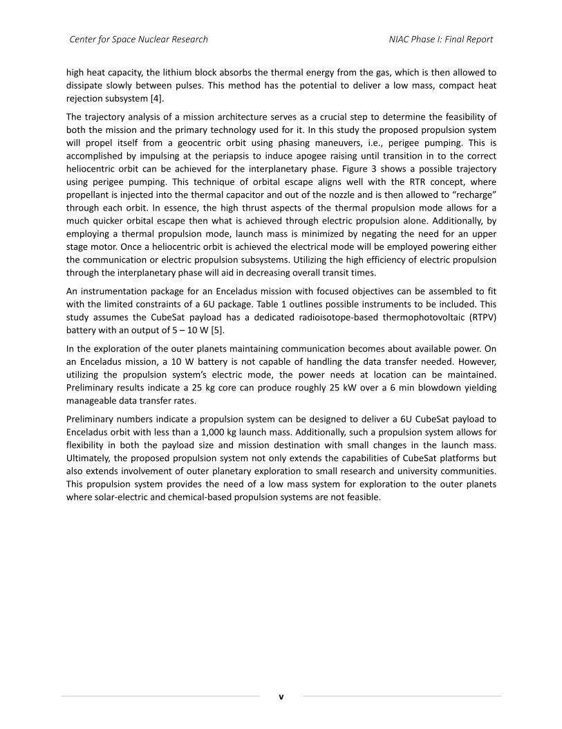
The trajectory analysis of a mission architecture serves as a crucial step to determine the feasibility of both the mission and the primary technology used for it. In this study the proposed propulsion system will propel itself from a geocentric orbit using phasing maneuvers, i.e., perigee pumping. This is accomplished by impulsing at the periapsis to induce apogee raising until transition in to the correct heliocentric orbit can be achieved for the interplanetary phase. Figure 3 shows a possible trajectory using perigee pumping. This technique of orbital escape aligns well with the RTR concept, where propellant is injected into the thermal capacitor and out of the nozzle and is then allowed to “recharge” through each orbit. In essence, the high thrust aspects of the thermal propulsion mode allows for a much quicker orbital escape then what is achieved through electric propulsion alone. Additionally, by employing a thermal propulsion mode, launch mass is minimized by negating the need for an upper stage motor. Once a heliocentric orbit is achieved the electrical mode will be employed powering either the communication or electric propulsion subsystems. Utilizing the high efficiency of electric propulsion through the interplanetary phase will aid in decreasing overall transit times.
An instrumentation package for an Enceladus mission with focused objectives can be assembled to fit with the limited constraints of a 6U package. Table 1 outlines possible instruments to be included. This study assumes the CubeSat payload has a dedicated radioisotope-based thermophotovoltaic (RTPV) battery with an output of 5 – 10 W [5].
In the exploration of the outer planets maintaining communication becomes about available power. On an Enceladus mission, a 10 W battery is not capable of handling the data transfer needed. However, utilizing the propulsion system’s electric mode, the power needs at location can be maintained. Preliminary results indicate a 25 kg core can produce roughly 25 kW over a 6 min blowdown yielding manageable data transfer rates.
Preliminary numbers indicate a propulsion system can be designed to deliver a 6U CubeSat payload to Enceladus orbit with less than a 1,000 kg launch mass. Additionally, such a propulsion system allows for flexibility in both the payload size and mission destination with small changes in the launch mass. Ultimately, the proposed propulsion system not only extends the capabilities of CubeSat platforms but also extends involvement of outer planetary exploration to small research and university communities. This propulsion system provides the need of a low mass system for exploration to the outer planets where solar-electric and chemical-based propulsion systems are not feasible.
Center for Space Nuclear Research NIAC Phase I: Final Report
vi
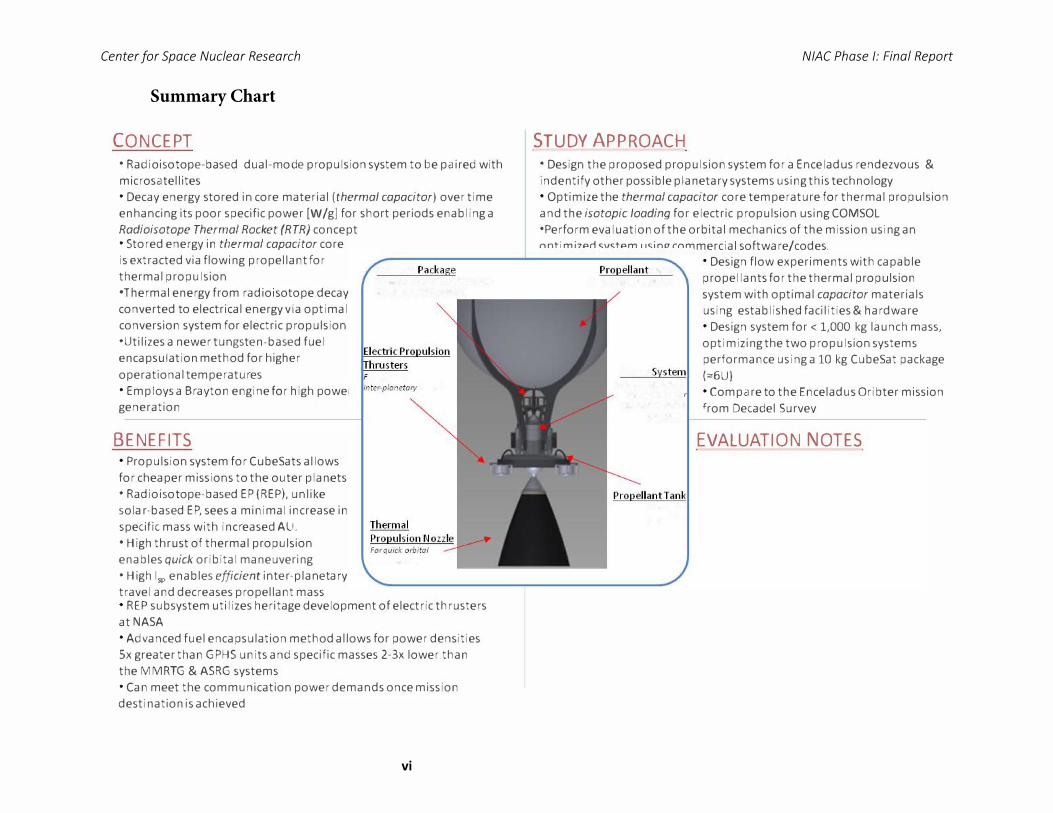
�---------....1..-----------CubeSat Package Propellant Tank Instrumentation in a 6U volume
2x(10cmx lOcmx 30cm)
oreffkient
inter-planetary trove/
monuevering
For them1al propulsion
Power System Radioisotope--based
energy input fo
thermal & electric
propulsion
For�Jectric
propulsion
Summary Chart
CONCEPT
• Radioisotope-based dual-mode propulsion system to be paired with microsatellites • Decay energy stored in core material (thermal capacitor) over time enhancing its poor specific power [W /g) for short periods enabling a Radioisotope Thermal Rocket (RTR) concept • Stored energy in thermal capacitor core is extracted via flowing propellant for thermal propulsion •Thermal energy from radioisotope decay converted to electrical energy via optimal conversion system for electric propulsion •Utilizes a newer tungsten-based fuel encapsulation method for higher operational temperatures • Employs a Brayton engine for high power generation
STUDY APPROACH
• Design the proposed propulsion system for a Enceladus rendezvous & indentify other possible planetary systems using this technology • Optimize the thermal capacitor core temperature for thermal propulsion and the isotopic loading for electric propulsion using COMSOL •Perform evaluation of t he orbital mechanics of the mission using an optimized system using commercial software/codes.
• Design flow experiments with capable propellants for the thermal propulsion system with optimal capacitor materials using established facilities & hardware • Design system for< 1,000 kg launch mass, optimizing the two propulsion systems performance using a 10 kg CubeSat package (::::6U) • Compare to the Enceladus Oribter mission from Decadel Survey
BENEFITS
• Propulsion system for CubeSats allows for cheaper missions to the outer planets • Radioisotope-based EP(REP), unlike solar-based EP, sees a minimal increase in specific mass with increased AU. • High thrust of thermal propulsion enablesquickoribital maneuvering • High lsp enablesefficientinter-planetary travel and decreases propellant mass • REP subsystem utilizes heritage development of electric thrusters at NASA • Advanced fuel encapsulation method allows for power densities Sx greater than GPHS units and specific masses 2-3x lower than the MMRTG & ASRG systems • Can meet the communication power demands once mission destination is achieved
EVALUATION NOTES
Center for Space Nuclear Research NIAC Phase I: Final Report
1
1.0 Introduction
It is apparent the cost of conducting planetary exploration is rising. Conversely, the budgets to fund such large scale missions are declining. These missions utilize integrated payloads comprised of numerous advanced instruments working together to accomplish a list of science-based objectives. The use of these advanced systems is important to our planetary science strategies and yield large science returns; however, their success comes at a large cost.
Over the past decade, small scientific beds geared to performing limited tasks have been developed and launched in to low earth orbit (LEO) in the form of small-scale satellite units. These micro- and nano-satellites are gaining popularity among the University and science communities due to their relatively low cost and design flexibility by following the popular CubeSat standard. CubeSats come in various sizes, all based on the 1U design (10cm x 10cm x 10cm). To date these small units have been limited to performing tasks in LEO utilizing primarily solar photovoltaic arrays for power. The advancement of technology in the area of complex micro-electronic packages has enabled the evolution of CubeSat platforms. However, the primary limitations of these small-test beds have been in the area of available power and mobility whose development have lagged behind and remain large and bulky limiting their research capabilities. In relying on photovoltaic arrays, available power becomes limited by the surface area of the CubeSat platform and the solar incidence of the orbit. Larger platforms such as a 3U or 6U have included the use of deployable arrays, but available power is still limited and intermittent. The lack of continuous power greatly influences the instruments ability to conduct science and more importantly the system’s communication capabilities. For mobility, several propulsion systems have been proposed for use in CubeSat platforms with the most common being cold gas thrusters. Electric propulsion systems have also been developed in various forms, such as vacuum arc thrusters and pulsed plasma thrusters. Overall, these propulsion systems typically occupy up to a 1/2U of volume and become limited in the total ΔV they can deliver to the platform.
Therefore, if a system could be developed for these CubeSat platforms that incorporate a propulsion system that also enhances the power available to these platforms, then the use of these micro – & nano – satellite platforms could be extended out of LEO and be used to perform exploration of various extra-terrestrial bodies. Researchers at the Center for Space Nuclear Research (CSNR) have proposed a radioisotope-based, dual-mode, low mass propulsion system capable of extending the exploration realm of these CubeSats out of LEO. Such a propulsion system would allow for beneficial exploration to be conducted within limited budgets. This in turn, would open the research potential of our solar system not only to NASA, but to small research groups and universities alike essentially expanding our knowledge base exponentially. This report outlines the research conducted through the first phase contract under a NASA Innovative Advanced Concepts (NIAC) award. This nine-month study focused on concept development and the feasibility of such a propulsion system designed to deliver a 6U CubeSat to the orbit of Enceladus with a total launch mass below 1,000 kg.
1.1 Overview
Several types of systems can be employed to provide the propulsion needed, but an ideal system is optimized for low mass and high performance. Chemical-based propulsion systems can be made, but they are massive and their performance becomes insufficient to allow deep space missions in reasonable times. Electric propulsion (EP) is very efficient but inherently has a very low acceleration, leading to long mission times. In addition, EP is commonly paired with solar photovoltaic arrays for power, which leads to an increased ship mass as the exploration distance from the Sun increases, i.e. increase in AU. Instead, pairing with radioisotope sources allows for electric propulsion to be used for
Center for Space Nuclear Research NIAC Phase I: Final Report
2
exploration to our outer planets where solar intensities are largely decreased, while maintaining a lower overall specific mass. Recent advances in efficient power conversion systems now make possible a hybrid propulsion system that is ideally suited for deep space missions for microsatellite packages. The proposed dual mode propulsion platform is a radioisotope-based system that capitalizes on the benefits of two types of propulsion methods; the high thrust of thermal propulsion (TP) for quick orbital maneuvers and the high specific impulse of electric propulsion for efficient inter-planetary travel.
Thermal propulsion provides high thrust, which becomes useful in escaping the orbits of planetary bodies, e.g. Earth. The CSNR has been developing a Martian surface exploration platform, the Mars Hopper, which utilizes radioisotope-based thermal propulsion technology that could enable a small, compact, high thrust system. The Mars Hopper concept utilizes energy from radioisotopic decay in a manner different from any existing radioisotope power source – as a thermal capacitor [6]. Radioisotopes have very high specific energies [J/kg] making their use as a primary energy source attractive. For example, the radioisotope 238Pu can deliver 1.6 x 10⁶ MJ/kg, which is roughly 160,000 times the specific energy of LO2/LH2 systems (10 MJ/kg). However, radioisotopes exhibit a low specific power – 238Pu has a specific power of 0.392 W/g. But by accumulating the thermal energy from radioisotopic decay over long periods within the propulsion system’s central core, the specific power of the core can be enhanced and the overall power of the system can be dramatically increased for short periods. This in turn, led to the development of a radioisotope-based thermal rocket (RTR).
Electric propulsion using radioisotope-based systems are possible, but unfortunately current radioisotope systems like the MMRTG (358 kg/kWe) and ASRG (228 kg/kWe) are too massive, i.e. the specific mass is so high that little acceleration of the ship would be produced. With the advent of newer technologies driving thermal photovoltaic (TPV) conversion to greater efficiencies they are proving to be more attractive as a low-mass conversion system. Thus, enabling electrically propelled craft to travel to far planets and provide power to the instruments upon arrival. The CSNR is currently developing radioisotope-based thermal photovoltaic (RTPV) battery systems that offer the possibility of 50-70 kg/kW – a factor of 2-3 lower than current systems. This conversion technology has great promise and can be used to provide electrical power to the system.
In order to drive to a lower specific mass [kg/kW] system, core modules with greater power densities must be developed. Currently a GPHS unit is the industrial standard, but they require a large volume and mass to deliver the needed power. Additionally, GPHS units are further limited, having a maximum operating temperature of around 1,000°C. The CSNR proposes a more direct containment method by encapsulating radioisotopes in a high temperature matrix through modern powder metallurgical sintering techniques, which will lead towards a high density fuel form. The concept being reported here will utilize such an encapsulation technique to house the radioisotope fuel. This will provide a greater energy density core as well as allow for a greater operational temperature than can be provided by current hardware.

Center for Space Nuclear Research NIAC Phase I: Final Report
3
2.0 Concept
The funcionality of the overall system relies on the integration of several key components – the energy source, thermal storage media, the insluation scheme, gas flow design, energy conversion and propulsion system. The energy source must be properly contained for safety and should provide a high energy density fuel form. The thermal storage media must also be properly contained and designed around the fuel form in order to efficiently use the provided energy. The development of the insulation scheme must be inherent to that of the thermal storage system to ensure the system will reach, maintain and operate at the designed temperatures in order to achieve the designed performance. The thermal storage media must also include a gas flow design, for energy to be extracted from the core and used to operate the conversion subsystem or for thermal propulsion.
2.1 Thermal Subsystem
As mentioned the system concept relies on the decay energy from radioisotopes. Radioisotopes in general exhibit very high specific energies [J/kg], however, they have poor specific powers [W/g]. Several radioisotopes have the potential to be used for the system concept. Table 1 tabulates several potential radioisotopes and their properties.
Table 1 Tabulated values of radioisotopes [6,7]
Isotope Specific Power [W/g] T1/2 [yrs] 238Pu* 0.392 87.7 90Sr† 0.254 28.8
244Cm‡ 2.269 18.1 241Am§ 0.094 432.7
*Assumes 80% isotopic purity and 88% compound mass in 238PuO2
†Assumes 57% isotopic purity and 48% compound mass in 90SrTiO3
‡Assumes 90% isotopic purity and 91% compound mass in 244Cm2O3 §Assumes 98% isotopic purity and 88% compound mass in 241AmO2
The radioisotope chosen to be the energy source for this concept was 238PuO2. Compared to the other radioisotopes presented in the above table 238Pu has a good specific power and a long half life. In general, working with 238PuO2 is less problematic then those radioisotopes having greater specific powers and its decay products are more easily shielded against. Additionally, this plutonium isotope has a long historical use in NASA and is already flight qualified, being used for numerous NASA deep space missions, e.g., New Horizons, Curiosity, Cassinni, etc.
Housing the radiosotope will be accomplished by directly encapsulating it within a tungsten – rhenium matrix to form the radioisotope heat source (RHS) for the system. This encapsulation method has been extensively studied at the CSNR and has been developed as the next-generation fuel form for nuclear thermal propulsion (NTP). Figure 1 shows an early concept of the NTP fuel form based on tungsten encapsulation developed at the CSNR. This encapsulation concept relies on the radioisotope-of-choice to be fabricated in to microspheres (dia. ≈ 100 µm) which are then directly sintered in to a tungsten-based matrix. In this study an isotope loading of 50 vol. % was used within the tungsten-rhenium matrix. Where the encapsulation matrix was comprised of tungsten – 25 at. % rhenium metals.

Center for Space Nuclear Research NIAC Phase I: Final Report
4
Figure 1: Early NTP fuel form concept [8]
R.C. O’Brien et al. indicates that a solid, tough, high-temperature tungsten-rhenium matrix can be formed to encapsulate radioisotopes commonly used for power production [2]. The thought is this tungsten-based matrix would be robust and provide the strength needed to prevent the dispersion of the radioisotope inventory through launch abort scenarios, atmospheric re-entries and planetary impacts in the case of a failed in-situ probe deployment. Through this method of radioisotope encapsulation, it is believed the core module’s power density can be increased by nearly five times compared to the traditional GPHS units.
The primary component of the conceptual system is the thermal capacitor; whose functionality drives the entire RTR concept. As previously described the thermal capacitor accumulates thermal energy from the radioisotopes over time. Then the stored thermal energy is extracted quickly by a flowing gas. Depending on the gas used the extracted thermal energy can be converted to thrust by use of a converging-diverging nozzle or converted to electrical power through the use of an energy conversion system.In determing an adequate material to act as the thermal capacitor several qualifications must be met:
1. The material must have high thermal storage capabilities – to accumulate a large amount of energy within a given volume
2. The material must have a high thermal conductivity – to dissipate stored thermal energy quickly to a flowing gas
3. The material must have a high melting temperature – allows for a high operational temperature increasing the systems performance
Thermal storage can primarily be accomplished through two methods – sensible heat storage and latent heat storage. Sensible heat storage is the energy stored in a material over a certain temperature range and is described by the material’s specific heat capacity [Cp]. Several materials have excellent sensible heat storage and the graph given in Figure 2 shows the heat capacity of several materials plotted over a given temperature range.
Beryllium is seen to be an excellent candidate material for sensible heat storage (Cp = 1.83 J/g-K, Tmelt = 1551 K & k = 201 W/m-K) allowing for an operational temperature of 1200 K [10]. It has the potential to store over 2 MJ/kg over the temperature range of 500 – 1200K. Additionally, boron would also make a good thermal capcitor material (Cp = 1.03 J/g-K, Tmelt = 2348 K & k = 27 W/m-K) [9]. Boron allows for a higher operational temperature, which in turn allows for a greater amount of energy storage because of the larger temperature range a boron thermal capacitor can operate over. Both beryllium and boron were considered previously in the CSNR’s Mars Hopper concept, with beryllium being focused on as the primary thermal capacitor material for that application. Boron wasn’t chosen because its use required an operational temperature greater than 2000 K in order for its thermal storage potential to

Center for Space Nuclear Research NIAC Phase I: Final Report
5
exceed that of beryllium. It was determined thermal cycling at those temperatures could present a significant challenge to the system and reaching those temperatures using radioisotopes would be equally challenging.
Figure 2: Plots the heat capacity versus temperature of several materials [9-14]
Latent heat thermal storage is the energy stored in a material through its phase change and is described by a material’s latent heat of fusion [ΔHfusion]. Several phase change materials (PCM) can be utilized depending on the application. Terrestrial based systems using latent heat thermal storage typically use molten salts as their PCM, however, their low melting temperatures and their low potential to store thermal energy do not make them ideal for this application. Silicon was determined to be and ideal PCM (ΔHfusion = 1.8 MJ/kg, Tmelt = 1685 K & k = 148 W/m-K) matching the storage performance of beryllium [3]. Because melting silicon is the primary goal, using it allows for an operational temperature approaching 1700 K. Several PCM materials are tabulated in Table 2 for comparison. Boron is also a very attractive choice as a PCM having a ΔHfusion = 4.3 MJ/kg but the same challenges listed above would need to be overcome [15].
Table 2: PCM materials [3,15,16]
Material ΔHfusion
[MJ/kg] Tmelt [K]
K
[W/m-K]
Silicon 1.80 1685 148
Boron 2.09 2348 27
LiF* 1.04 1121 --
LiH* 2.58 956 --
80LiOH + 20LiF* 1.16 700 --
*molten salts

Center for Space Nuclear Research NIAC Phase I: Final Report
6
In determining which thermal storage method is best each present unique challenges. Sensible heat storage systems exhibit non-isothermal behavior as they discharge their stored energy. This equates to a continually decreasing core exit gas temperature through the blowdown process. In turn this means the chamber temperature of the propellant gas or the turbine inlet temperature is constantly changing; complicating the design of these subsystems. In general latent heat storage systems are favorable because their temperature is held relatively constant at the phase change temperature as they accumulate and discharge energy. This isothermal behavior simplifies the system design and limits its thermally cycling. Figure 3 shows a simplified example of sensible vs latent heat storage over a temperature range.
Figure 3: Graphic displaying sensible vs latent heat storage
For the concept reported here the thermal capacitor was determined to be silicon. Silicon exhibits a high energy storage potential, operational temperature and thermal conductivity and overall simplifies the system’s design. In using a PCM as the thermal capacitor there are several challenges that will need to be addressed in future work. However, these challenges can be overcome by building on experience gained through terrestrial applications of PCMs and through NASA’s long research history on solar-thermal energy storage systems.
The major technical challenges in using silicon as the thermal capacitor is first in containing its liquid phase, as well as handling its liquifying – freezing cycle. During a blowdown sequence as energy is dissipated and the core re-solidifies uneven freezing can form void spaces, which in turn can introduce stresses into the insulation layers surrounding the central core. To deter possible insulation fracturing the thermal capacitor can be first contained within a canister that provides structural rigidity to the system and can withstand core volume fluctuations through the phase change cycling. At the proposed operational temperatures this housing will most likely be a refractory metal or alloy, e.g. a molybdenum- or tungsten- based alloy. The silicon core canister would be fabricated as a shell with tubes running axially acting as the flow channels. The canister wall thickness will be several millimeters in the periphery and a minimal wall thickness at the flow channels. Initially, the flow channels will be 2 mm in diameter, which was used for the Mars Hopper core. The distance between flow channels (web thickness) will be minimal to minimize hot spots and to ensure all stored energy can be extracted. However, these parameters could also affect the stresses associated with the silicon freezing cycle. One thought is increasing the web thickness will allow more expansion room for the silicon before encountering another flow channel tube, minimizing the applied stresses to the canister. Ultimately, future work using computational fluid dynamic (CFD) modeling will be needed to determine the ideal

Center for Space Nuclear Research NIAC Phase I: Final Report
7
flow channel size and web thickness. And this analysis will need to be completed concurrently to stresses in the thermal capacitor.
Another challenge is observed as the silicon transitions to its liquid phase as it accumulates thermal energy from the RHS. As the silicon liquefies its volume decreases by up to 8% leaving void spaces within the canister. The formation of these voids spaces has the potential to create a loss in conductive pathways to the walls of the canister and flow channels. Modeling will need to be conducted to determine the significance of this effect but it may affect the thermal hydraulics within the thermal capacitor. Experimentation cycling silicon through its phase change will need to be conducted in order to gain a better understanding of the volume change phenomenon, which is seen as a major technical challenge in using silicon. Addressing the possible loss in thermal conductivity of the thermal capacitor as a whole when at operating temperatures will need to be investigated further.
2.2 Thermal Subsystem Modeling
The thermal and radiative losses were somewhat problematic in the design of the core, as working with such high temperatures allows heat to escape through mounting systems or by radiation. To combat both effects, an insulating material was included on the outer walls of the core. This allowed the core to stay hot enough to melt the silicon, while keeping the outside walls of the insulation cool enough to limit radiative losses. It also doubled as a structural mounting material as well as conductive loss limiter. Based on thermal and structural properties, zirconia (ZrO2) was selected to be the primary insulator, with a carbon aerogel secondary insulator being used in areas where no stresses will be experienced. Table 3 shows the material properties of the insulation materials that were used in the COMSOL Multiphysics modeling, which are internal to the software.
Table 3: Material properties of insulation materials used in modeling Insulating Material
Specific Heat [J/kg*K]
Thermal Conductivity [W/m*K]
Density [kg/m3]
Zirconia 400 3 5700
Carbon Aerogel 754 0.03 2230
It should be noted, upon further development of the thermal propulsion system the use of hydrogen gas as the primary propellant was determined to be ideal. In using hydrogen the zirconia insulation may be placed in a reducing environment, inadvertently degrading the insulating material. Because of this, alternatives such as boron nitride and zirconium carbide were examined as alternatives. However, no other option had the same thermal insulation characteristics while maintaining the structural integrity necessary to support the core. Thus the use of a hydrogen-compatible material, such as boron nitride or tantalum would be used as a possible cladding to form a protective barrier between on the zirconia. Additionally, an adequate cladding’s thermal expansion would need to be considered in order to ensure stability through thermal cycling. Further investigations of possible insulation cladding materials and application methods will be necessary in follow on work.
The design for the core was concluded with the assumptions that the zirconia insulation would incorporate a protective cladding from the hydrogen, the metallic housing for the molten silicon had negligible thermal effects, and that the silicon expansion could be overcome. With these aspects in mind, the central core containing the silicon and fuel rods has a diameter of 18.5 cm and a length of 30 cm. The core is radially insulated by a zirconia sheath with a thickness of 5 cm and axially insulated by a zirconia cap top and bottom, each having an 18.5 cm diameter and 20 cm length. Around that assembly is a carbon aerogel secondary insulation layer, having a 40 cm diameter and 70 cm length. Four tantalum rods of 0.4 cm diameter attached the zirconia insulation to the housing of the unit to act
Center for Space Nuclear Research NIAC Phase I: Final Report
8
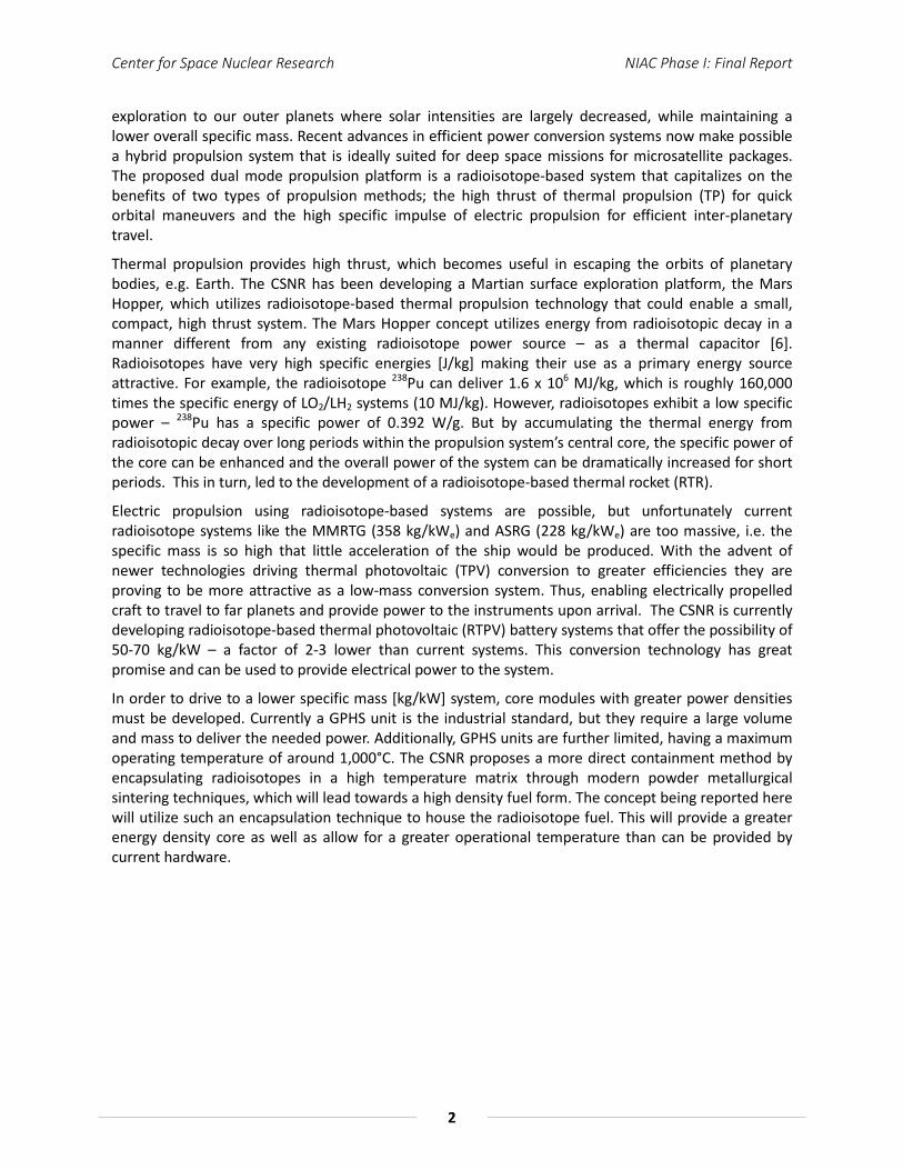
as a support structure for the overall core assembly. Often at this level of concept development the incorporation of a support structure may seem trivial. However, it was important to include the support structure in to the modeling; previous experience has shown with such small core dimensions conductive losses at these points can be significant. A diagram of the preliminary core design can be seen below in Figure 4.
Figure 4: COMSOL Model of Core geometry
The core was powered by 3 kg of PuO2, having a power density of 0.392 W/g, for a total of 1.18 kWt of input heat to the system. The loaded fuel rods had a total mass of 6.44 kg, the mounting structure 2.1 kg and the insulation 108 kg. The core used 15.58 kg of silicon, giving the core a total mass of 132. kg. A breakdown of the thermal subsystem component masses are listed in Table 4.
Table 4: Mass breakdown of thermal subsystem
Core Component Mass [kg]
Silicon PCM 15.58
PuO2 Loaded Fuel Rods 6.44
ZrO2 Insulation 108
Mounting Structure 2.1
Total Mass 132.12
The core was designed to operate at 1685 K continuously, and it would alternate between totally molten to totally solid. Thermal models predicted at that temperature, 795 Wt of thermal energy would escape through conductive and radiative losses. This left 385 Wt from the total 1180 Wt provided to melt the core. The total melting of the core was found to take 20.5 hours to complete. The silicon capacitor was capable of storing 30 MJ of energy, which if discharged over 360 seconds and

Center for Space Nuclear Research NIAC Phase I: Final Report
9
converted to electricity at 30% efficiency, would provide 25 kWe of electrical power. A COMSOL model of the core geometry operating at 1681 K can be seen in Figure 5. For the purposes of computational modeling, the 4 K difference between the modeling temperature and melting temperature was assumed to be within acceptable bounds.
Figure 5: COMSOL model showing the thermal performance of the thermal system
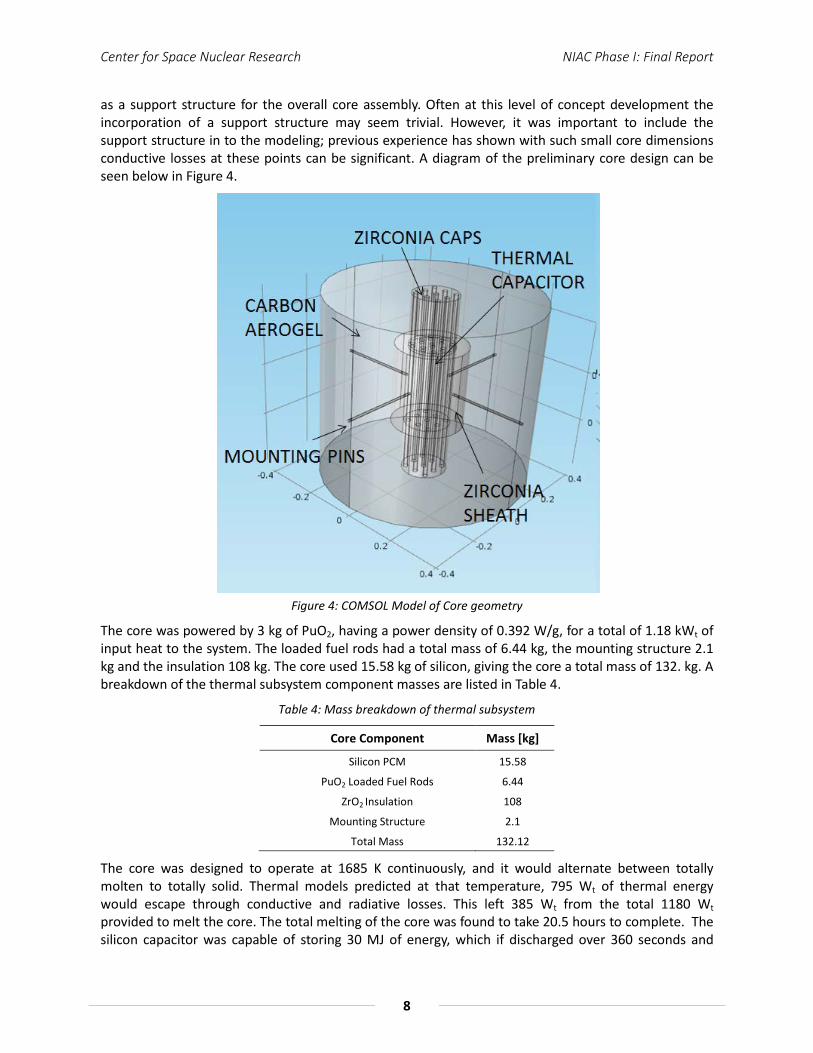
Further modeling was conducted to ensure complete melting of the silicon core was accomplished. This incorporated a heterogeneous central core comprising of the silicon thermal capacitor with six RHS rods distributed. It was determined utilizing rods radially spaced within the silicon core provided the most equal dissipation of thermal energy in to the thermal capacitor. Figure 6 shows the melting of the core over time with six fuel rods distributed throughout.
The melting of the core was modeled by utilizing a 2-dimensional model with added parameters for the phase of the material at different temperatures and the absorption of the input heat by melting. The power in was found by dividing the total thermal input (1.18 kWt) evenly between the six solid fuel rods. The outer edge of the silicon core was established with a constant, 795 Wt heat flux to represent the heat lost through the insulation. While the model did take in to account the length of the core for the purposes of calculating exposed areas, it did not examine the changes to the melting profile near the edges; it was assumed for this profile that edge effects could be neglected.
As the model ran, the input energy was absorbed by the silicon material as it went through the phase change. Only once the material had melted, was the temperature allowed to increase. This created a melting profile that slowly extended away from the hot fuel rods, until the entire core had become liquid.
Center for Space Nuclear Research NIAC Phase I: Final Report
10
Figure 6: COMSOL model detailing the incremental melting of the PCM thermal capacitor
2.3 Operational Modes
The concept relies on the function of two modes to accomplish the overall goals of a mission. At the center of the operation is the thermal capacitor, discussed above. The thermal capacitor accumulates thermal energy that can be made available for different operations and/or functions of the entire system. The two operational modes discussed in greater detail below are the thermal mode and electrical conversion mode. The thermal mode takes advantage of the stored thermal energy transferring it to propellant injected in to the core. In turn, the now energized propellant flows through a converging-diverging nozzle creating thrust. The second operational mode is converting the stored thermal energy to electrical power to be used for electric propulsion, communications, etc. There were two primary energy conversion methods identified that could be used with this system – thermal photovoltaic (TPV) or a Brayton cycle. Each system provides power in two drastically different manners. A TPV system can be designed to utilize thermal radiation from the core and convert it to useable electrical power. This adds an element of complexity in designing the overall core system. In one hand the thermal capacitor is insulated to reach a certain operational temperature, however, on the other hand radiative losses are needed to provide electrical power. A TPV system is a solid-state conversion method that can provide continuous power, but would need a capacitor bank when the system requires bursts of high power. A Brayton-based conversion system is a dynamic cycle and when pulsed can produce the bursts of higher power that may be needed by a communication subsystem. For the study reported here a TPV system and Brayton engine were compared and the system needs lead to
Center for Space Nuclear Research NIAC Phase I: Final Report
11
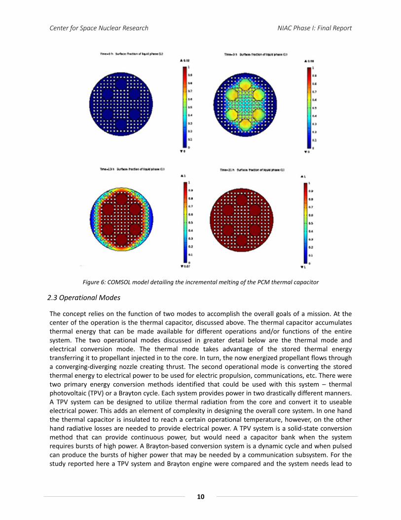
the incorporation of dual 12.5 kW Brayton engines that share a single compressor. The primary choice of the Brayton system was due to the high power requirements initially identified by the communication system and its ability to be paired with the thermal capacitor. The operation of the Brayton system comprises of passing a working fluid through the thermal capacitor, extracting the stored thermal energy and converting that to electrical power through the use of a turbine and alternator. Figure 7 shows the two flow schematics representing each operational mode and how they may be integrated in to the system. The electrical conversion mode will be discussed in greater detail below, where the thermal mode and its operation is discussed in greater detail later.
(a) (b)
Figure 7: Shows the flow schematics for the two operation modes where (a) thermal operation mode and (b) is the electrical conversion operation mode
2.4 Conversion Subsystem
For power generation, a Brayton cycle was selected based on its high efficiency, low waste heat, and ability to utilize the thermal capacitor of the core effectively. A Rankine cycle, for comparison, needs to reject large amounts of heat to return the working fluid to the beginning liquid state. Instead, a Brayton cycle’s major loss mechanism is the power taken by the compressor to return the fluid to the starting state. While both cycles are quite efficient, rejecting waste heat in space usually requires the use of massive radiators that contribute greatly to the size and weight of the craft.
The Brayton cycle analysis required a total conversion efficiency of 30% by utilizing an operating temperature of up to 1687 K. To achieve this, a working fluid was blown through the hot core, and passed through two, 12.5 kW turbines. The fluid then passed through an absorber material to collect the remaining waste heat, and then on to a compressor to return to the starting state. After the 360 second blowdown, the core would slowly melt again, and the absorbers could safely radiate the waste heat to space without the need for large fins, and be ready for the next cycle after 21 hours.
The thermodynamic analysis of the Brayton cycle resulted in a working fluid of helium, and the characteristics represented in Table 5.
Center for Space Nuclear Research NIAC Phase I: Final Report
12
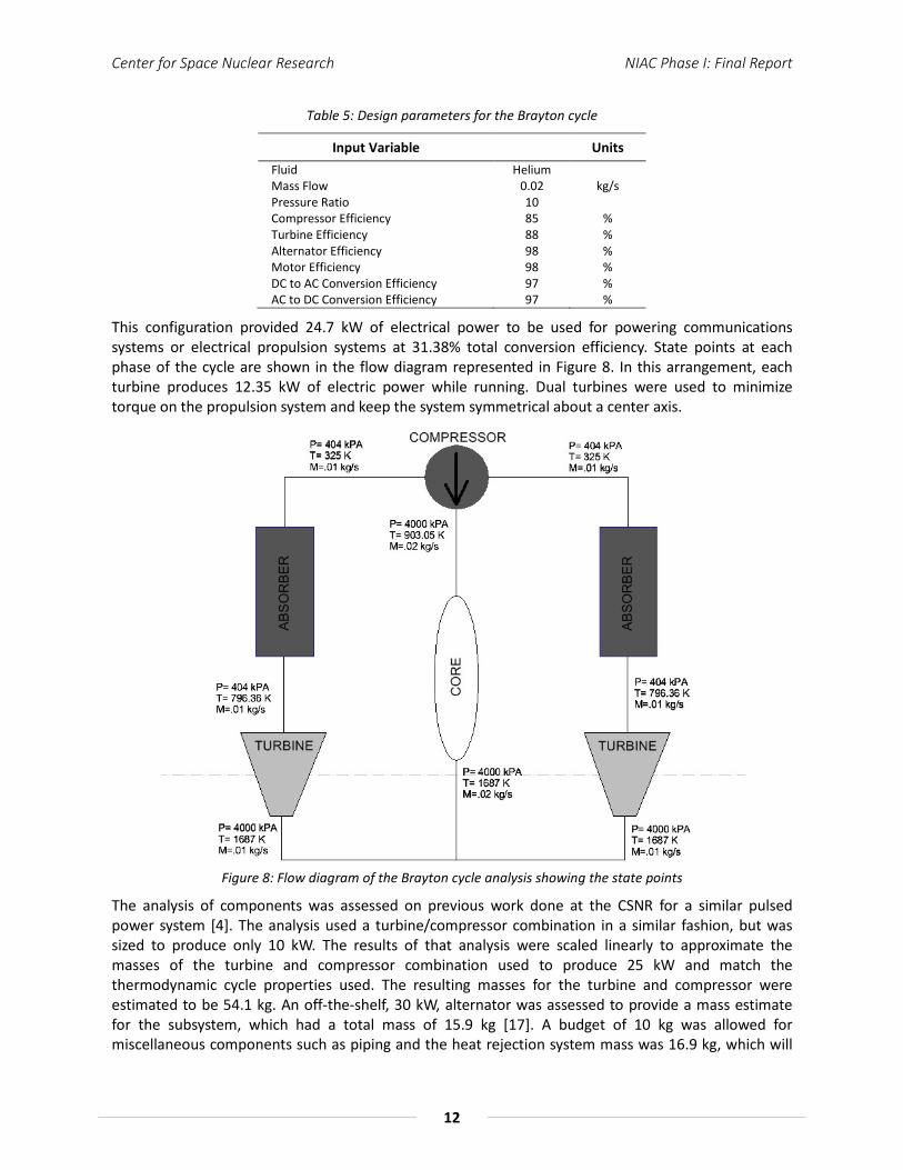
Table 5: Design parameters for the Brayton cycle
Input Variable Units Fluid Helium Mass Flow 0.02 kg/s Pressure Ratio 10 Compressor Efficiency 85 % Turbine Efficiency 88 % Alternator Efficiency 98 % Motor Efficiency 98 % DC to AC Conversion Efficiency 97 % AC to DC Conversion Efficiency 97 %
This configuration provided 24.7 kW of electrical power to be used for powering communications systems or electrical propulsion systems at 31.38% total conversion efficiency. State points at each phase of the cycle are shown in the flow diagram represented in Figure 8. In this arrangement, each turbine produces 12.35 kW of electric power while running. Dual turbines were used to minimize torque on the propulsion system and keep the system symmetrical about a center axis.
Figure 8: Flow diagram of the Brayton cycle analysis showing the state points
The analysis of components was assessed on previous work done at the CSNR for a similar pulsed power system [4]. The analysis used a turbine/compressor combination in a similar fashion, but was sized to produce only 10 kW. The results of that analysis were scaled linearly to approximate the masses of the turbine and compressor combination used to produce 25 kW and match the thermodynamic cycle properties used. The resulting masses for the turbine and compressor were estimated to be 54.1 kg. An off-the-shelf, 30 kW, alternator was assessed to provide a mass estimate for the subsystem, which had a total mass of 15.9 kg [17]. A budget of 10 kg was allowed for miscellaneous components such as piping and the heat rejection system mass was 16.9 kg, which will
Center for Space Nuclear Research NIAC Phase I: Final Report
13
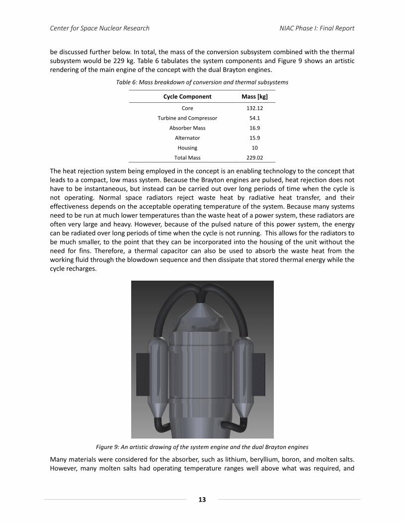
be discussed further below. In total, the mass of the conversion subsystem combined with the thermal subsystem would be 229 kg. Table 6 tabulates the system components and Figure 9 shows an artistic rendering of the main engine of the concept with the dual Brayton engines.
Table 6: Mass breakdown of conversion and thermal subsystems
Cycle Component Mass [kg]
Core 132.12
Turbine and Compressor 54.1
Absorber Mass 16.9
Alternator 15.9
Housing 10
Total Mass 229.02
The heat rejection system being employed in the concept is an enabling technology to the concept that leads to a compact, low mass system. Because the Brayton engines are pulsed, heat rejection does not have to be instantaneous, but instead can be carried out over long periods of time when the cycle is not operating. Normal space radiators reject waste heat by radiative heat transfer, and their effectiveness depends on the acceptable operating temperature of the system. Because many systems need to be run at much lower temperatures than the waste heat of a power system, these radiators are often very large and heavy. However, because of the pulsed nature of this power system, the energy can be radiated over long periods of time when the cycle is not running. This allows for the radiators to be much smaller, to the point that they can be incorporated into the housing of the unit without the need for fins. Therefore, a thermal capacitor can also be used to absorb the waste heat from the working fluid through the blowdown sequence and then dissipate that stored thermal energy while the cycle recharges.
Figure 9: An artistic drawing of the system engine and the dual Brayton engines
Many materials were considered for the absorber, such as lithium, beryllium, boron, and molten salts. However, many molten salts had operating temperature ranges well above what was required, and

Center for Space Nuclear Research NIAC Phase I: Final Report
14
they would not effectively cool the exhaust of the cycle. Boron and beryllium had acceptable specific heats at 1.03 kJ/kg-K and 1.83 kJ/kg-K, but beryllium is hazardous to handle and can make manufacturing quite difficult. Boron remains a viable contender but its thermal physical properties were not quite as impressive as lithium.
Lithium is an almost ideal candidate for waste heat absorption because of its high specific heat capacity (Cp = 3.58 kJ/kg-K). However, it has a melting temperature of only 453 K [18]. The turbine outlet temperature of the Brayton cycle is estimated to be about 796 K. This means that the leading edge of the lithium absorber could likely melt. However, a similar housing being employed for the thermal capacitor would be able to contain the molten lithium and maintain the integrity of the flow channels. Calculations and models show that the absorber, even if temporarily molten, would be able to absorb the amount of waste heat produced and radiate back to starting temperatures over the course of 20 hours.
The final design of the absorber was a lithium cylinder having 2 mm diameter flow channels evenly distributed throughout. The length was found to be 50 cm and a diameter of 26 cm. Based on a thermal capacitor that could store 30 MJ, and a turbine that is at least 70% efficient, 16.9 kg of lithium absorber material would be needed to adequately capture the waste heat. For containment, an aluminum shell can be used to house the lithium having a wall thickness of 1 cm and a length of 90 cm. The aluminum shell was modeled with an emissivity value of 0.8 to represent an achievable permanent value, and the radiative view factor of the absorber was set to 75% of the cylindrical surface area. The model predicted the absorber temperature had cooled to 253 K after 20 hours, and the starting temperature before heat up was set to 255 K, indicating the absorber had returned to the initial state in the allotted time frame. Figure 10 shows the cooling profile of the absorber at different increments.
Figure 10: COMSOL model of the dissipation of thermal energy from the absorbers
It is believed, this absorber heat rejection system is a key technology to the operation of the proposed Brayton engine and its ability to both absorb the waste heat and dissipate it radiatively will need to be further evaluated. Ultimately, its utilization allows for a low mass, small footprint system that incorporates a dynamic conversion subsystem.
A TPV energy conversion system was also considered as an alternative power generation method to the Brayton cycle. Coupled with batteries or capacitors, a TPV system could provide bursts of electrical power that could reach the needed 25 kWe as well. However, based on calculations done on off-the-shelf super capacitors the mass of the capacitor bank would be extremely high. A TPV/capacitor system was evaluated and was found to have a mass of 0.94 kg and capable of providing 800 F of capacitance each [19]. Therefore, in order to provide the 9x10⁶ J needed to reach 25 kWe the capacitor bank would

Center for Space Nuclear Research NIAC Phase I: Final Report
15
have a mass burden approaching 4,000 kg. The mass need of the capacitor bank greatly exceeds not only the mass estimates of the Brayton engine, but that of the entire propulsion system. This further enforced our progression to designing a Brayton cycle conversion system.
Furthermore, using TPV system as a secondary power source was also investigated, but discarded due to the changes the inclusion of thermal photovoltaic conversion would have on the design of the core. As it is designed, the exposed surfaces of the core are at much lower temperatures than that of the thermal capacitor. In order for a TPV system to function, it needs an exposed hot surface that can transfer energy through radiation. The exposure of the hot core would require the removal of the insulation layers, and reduce the maximum operating temperature of the core. This in turn, negates the thermal storage potential of the silicon thermal capacitor, greatly affecting the thermal management of the overall system. Also, if the photovoltaic panels were placed at any point along the path of the working fluid or propellant, the stresses and temperatures they would encounter would quickly degrade them to the point of rendering them nonfunctional.
However, the inclusion of a secondary system to generate power on a smaller, more constant cycle may be beneficial to some applications. In order to achieve this, a smaller, secondary Brayton cycle could be used in order to accommodate the decreased mass flow and power output for continuous operation. A 100 We Brayton cycle would require a mass flow rate of only 0.08 g/s, and would otherwise mimic the performance of the larger, main cycle. In this case, the core would provide 325 Wt of thermal power to the cycle, which is below the levels of heat provided to the core by the PuO2 at 1685 K, thus the core would not decrease in temperature. However, it would significantly decrease the rate at which the core melted, and a full 20.5 hour rest period would need to be taken before switching back to the full power, larger Brayton system. The idea of this secondary system occurred later in the project and will need to be investigated further.
A technical challenge of using a Brayton engine is the reliability of the components over the mission lifetime. However, because the system is pulsed, the cycle operates for a significantly shorter amount of time over the entire mission. The current design of the Brayton system is to be pulsed once a day for 6 minutes. Over a 15 year mission, the cycle will only operate for 547.5 hours. Additionally, due to the operational temperatures (Tin ≈ 1700 K), the turbine can be at risk of thermal creep. However, the use of ceramic materials, such as Si3N2, can drastically increase turbine lifetime and operational temperatures. Potential turbine materials will need to be addressed and the potential operational lifetime of the system will need to be determined. Also, in implementing a possible secondary Brayton system the overall integration and operation becomes more complex. Furthermore, continuous operation, as opposed to pulsed operation, of the small system at operational temperatures may lead to thermal fatigue of the turbine components and pre-mature failure of that system. Furthermore, the heat rejection system is looked at as being an enabling technology to this system and will also need to be further developed through modeling as the Brayton system is further optimized. Thermal hydraulic experiments will also be important to perform, in order to demonstrate its ability to absorb waste heat.
Center for Space Nuclear Research NIAC Phase I: Final Report
16
3.0 Mission Architecture
The concept design was based around a Enceladus orbiter mission architecture. The mission design incorporated an evaluation of the science objectives laid out in the decadal survey for an Enceladus mission, as well as an assessment of potential instruments that can meet those objectives that fit with the payload frame envelope. Additionally, appropriate trajectories were generated at several phases of the journey, with the ultimate destination being the Saturnian system and Enceladus orbit. The Earth escape phase of the journey
3.1 Design Approach
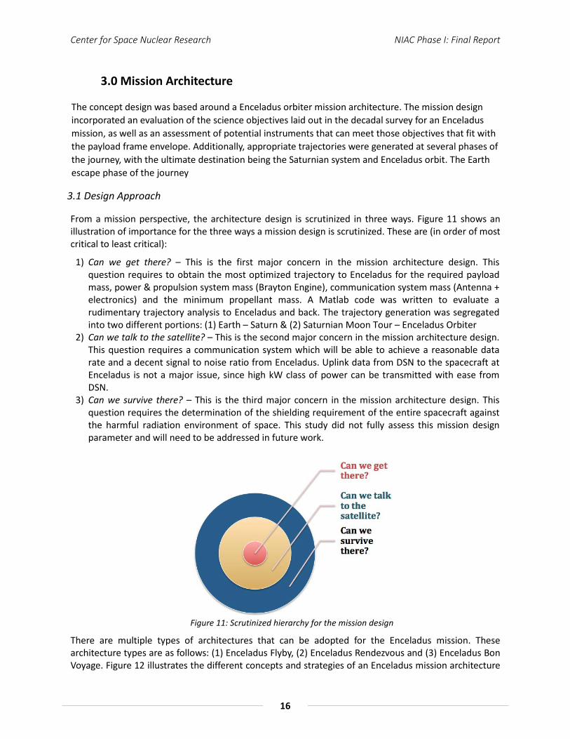
From a mission perspective, the architecture design is scrutinized in three ways. Figure 11 shows an illustration of importance for the three ways a mission design is scrutinized. These are (in order of most critical to least critical):
1) Can we get there? – This is the first major concern in the mission architecture design. This question requires to obtain the most optimized trajectory to Enceladus for the required payload mass, power & propulsion system mass (Brayton Engine), communication system mass (Antenna + electronics) and the minimum propellant mass. A Matlab code was written to evaluate a rudimentary trajectory analysis to Enceladus and back. The trajectory generation was segregated into two different portions: (1) Earth – Saturn & (2) Saturnian Moon Tour – Enceladus Orbiter
2) Can we talk to the satellite? – This is the second major concern in the mission architecture design. This question requires a communication system which will be able to achieve a reasonable data rate and a decent signal to noise ratio from Enceladus. Uplink data from DSN to the spacecraft at Enceladus is not a major issue, since high kW class of power can be transmitted with ease from DSN.
3) Can we survive there? – This is the third major concern in the mission architecture design. This question requires the determination of the shielding requirement of the entire spacecraft against the harmful radiation environment of space. This study did not fully assess this mission design parameter and will need to be addressed in future work.
Figure 11: Scrutinized hierarchy for the mission design
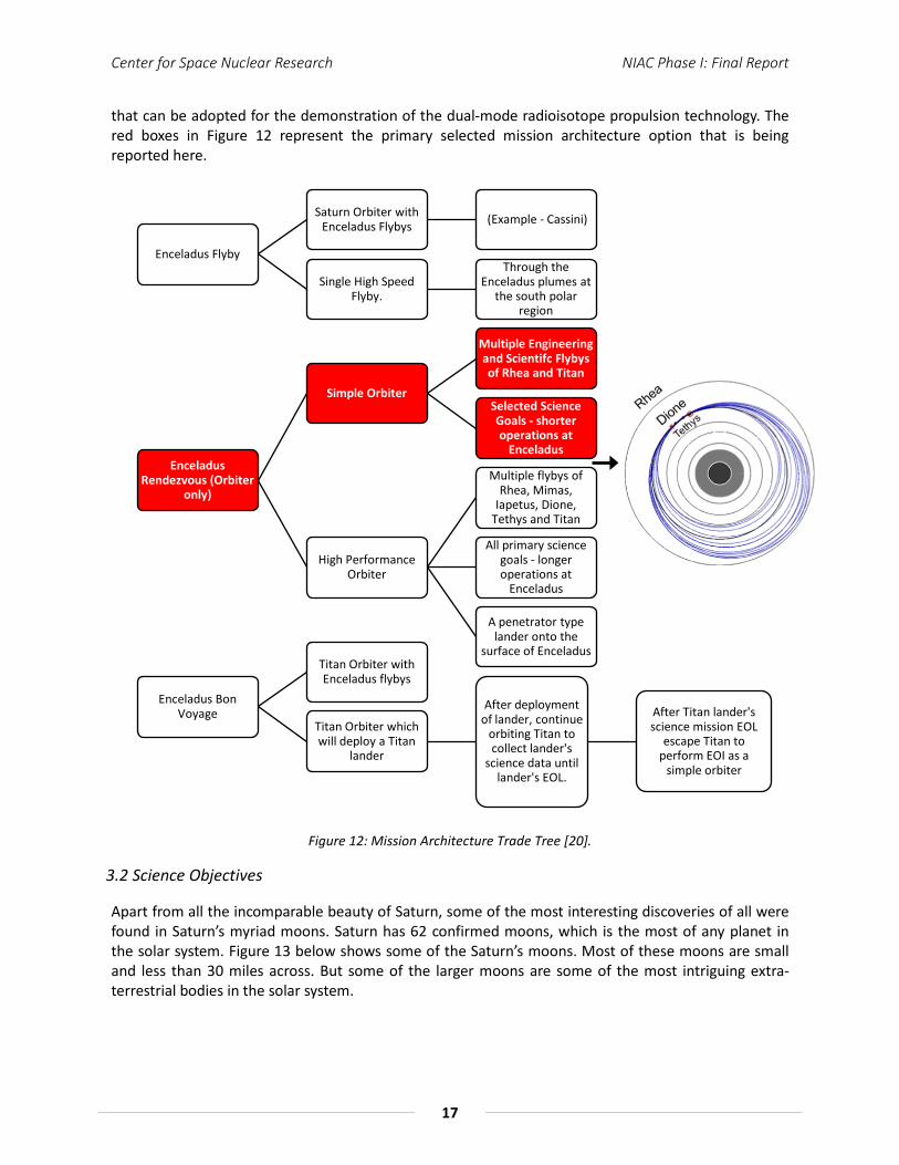
There are multiple types of architectures that can be adopted for the Enceladus mission. These architecture types are as follows: (1) Enceladus Flyby, (2) Enceladus Rendezvous and (3) Enceladus Bon Voyage. Figure 12 illustrates the different concepts and strategies of an Enceladus mission architecture
Center for Space Nuclear Research NIAC Phase I: Final Report
17
that can be adopted for the demonstration of the dual-mode radioisotope propulsion technology. The red boxes in Figure 12 represent the primary selected mission architecture option that is being reported here.
Enceladus Flyby
Saturn Orbiter with Enceladus Flybys (Example - Cassini)
Single High Speed Flyby.
Through the Enceladus plumes at
the south polar region
Enceladus Rendezvous (Orbiter
only)
Simple Orbiter
Multiple Engineering and Scientifc Flybys of Rhea and Titan
Selected Science Goals - shorter operations at
Enceladus
High Performance Orbiter
Multiple flybys of Rhea, Mimas,
Iapetus, Dione, Tethys and Titan
All primary science goals - longer operations at
Enceladus
A penetrator type lander onto the
surface of Enceladus
Enceladus Bon Voyage
Titan Orbiter with Enceladus flybys
Titan Orbiter which will deploy a Titan
lander
After deployment of lander, continue
orbiting Titan to collect lander's
science data until lander's EOL.
After Titan lander's science mission EOL
escape Titan to perform EOI as a
simple orbiter
Figure 12: Mission Architecture Trade Tree [20].
3.2 Science Objectives
Apart from all the incomparable beauty of Saturn, some of the most interesting discoveries of all were found in Saturn’s myriad moons. Saturn has 62 confirmed moons, which is the most of any planet in the solar system. Figure 13 below shows some of the Saturn’s moons. Most of these moons are small and less than 30 miles across. But some of the larger moons are some of the most intriguing extra-terrestrial bodies in the solar system.

Center for Space Nuclear Research NIAC Phase I: Final Report
18
(a) (b) (c) Figure 13: Saturn’s smaller moons – (a) Epimetheus, (b) Pandora and (c) Telesto [21-23].
For example Mimas (Figure 14 (b)) is recognizable from its massive crater that spans more than 80 miles in diameter. The crater is the remnant of an impact so violent; it nearly split Mimas into two. Iapetus is Saturn’s third largest moon and seems to have almost a split personality, with one side a soft white in color like snow and the other side a dark and tarnished surface. Running along the equator of this moon is a mountain ridge more than 800 miles long, 12 miles wide and reaching more than 42,000 feet high (higher than the Himalayas). The bizarre looking Hyperion (Figure 14 (d)) was the first non-spherical moon to be found. Its irregular shape, chaotic rotation and strange sponge like appearance remain unexplained.
(a) (b)
(c) (d)
Figure 14: Saturn’s larger moons – (a) Rhea, (b) Mimas, (c) Iapetus and (d) Hyperion [24-27].
But among the smaller icy moons of Saturn, none has generated more excitement and fascination than Enceladus. It is smaller than our own moon but is still one of the brightest objects in the solar system. Its frozen surface reflects nearly 100 % of the sunlight that hits on it. It was quite surprising for the science community when Cassini detected a hot zone at Enceladus’ South Pole. Closer inspection revealed a very active surface geology, with cracks and fissures continually forming and reforming in the icy crust. Cassini made several very close flybys of Enceladus and scientists were astounded by the discovery of huge plumes of water vapor and ice crystals continuously venting out into space from this southern hot zone. It soon became clear that these geysers where actually the material source for Saturn’s immense yet diffused “e-ring”. But even more significantly, they suggest that a liquid ocean
Center for Space Nuclear Research NIAC Phase I: Final Report
19
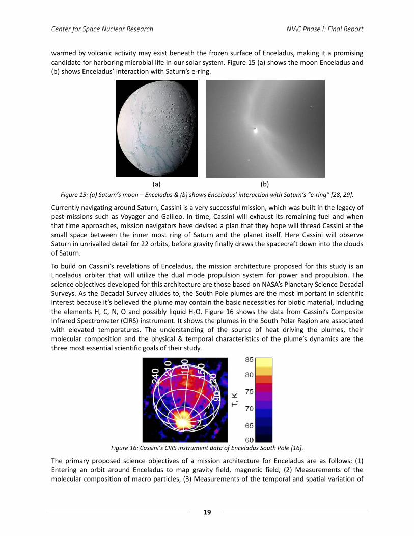
warmed by volcanic activity may exist beneath the frozen surface of Enceladus, making it a promising candidate for harboring microbial life in our solar system. Figure 15 (a) shows the moon Enceladus and (b) shows Enceladus’ interaction with Saturn’s e-ring.
(a) (b)
Figure 15: (a) Saturn’s moon – Enceladus & (b) shows Enceladus’ interaction with Saturn’s “e-ring” [28, 29].
Currently navigating around Saturn, Cassini is a very successful mission, which was built in the legacy of past missions such as Voyager and Galileo. In time, Cassini will exhaust its remaining fuel and when that time approaches, mission navigators have devised a plan that they hope will thread Cassini at the small space between the inner most ring of Saturn and the planet itself. Here Cassini will observe Saturn in unrivalled detail for 22 orbits, before gravity finally draws the spacecraft down into the clouds of Saturn.
To build on Cassini’s revelations of Enceladus, the mission architecture proposed for this study is an Enceladus orbiter that will utilize the dual mode propulsion system for power and propulsion. The science objectives developed for this architecture are those based on NASA’s Planetary Science Decadal Surveys. As the Decadal Survey alludes to, the South Pole plumes are the most important in scientific interest because it’s believed the plume may contain the basic necessities for biotic material, including the elements H, C, N, O and possibly liquid H2O. Figure 16 shows the data from Cassini’s Composite Infrared Spectrometer (CIRS) instrument. It shows the plumes in the South Polar Region are associated with elevated temperatures. The understanding of the source of heat driving the plumes, their molecular composition and the physical & temporal characteristics of the plume’s dynamics are the three most essential scientific goals of their study.
Figure 16: Cassini’s CIRS instrument data of Enceladus South Pole [16].
The primary proposed science objectives of a mission architecture for Enceladus are as follows: (1) Entering an orbit around Enceladus to map gravity field, magnetic field, (2) Measurements of the molecular composition of macro particles, (3) Measurements of the temporal and spatial variation of

Center for Space Nuclear Research NIAC Phase I: Final Report
20
the plumes and (4) Slower flybys for plume sample & surface mapping [29]. Based on the restriction in the space & mass envelope of the payload section and the mission architecture type, a selected list of science objectives (Table 7) are listed from the total list of all science objectives laid out in the decadal survey. This will be the list of science objectives, which the proposed mission will work towards in achieving.
Table 7: Science Traceability Matrix [29]
Science Objectives Science Investigation Instrument Payload
Physical conditions at the plume source
Topography & stratigraphy; Thermal output; vent shape; surface strength; surface roughness; subsurface structure of
tiger stripes; cavern size; subsurface lake; particle size distribution and speed; ice temperature
MAC, thermal imaging radiometer, dust
analyzer, MS
Chemistry of the plume source
Chemical inventory of plume gas and dust species; chemical equilibria; isotopic ratios
MS, dust analyzer
Presence of biological activity Organic molecules inventory to high masses MS, dust analyzer
Plume dynamics and mass loss rates
Plume structure, ejection rates; particle size vertical structure; particle velocities; time variability (density, particle size,
velocity; composition) MAC, MS, dust analyzer
Origin of south-polar surface features
Topography & stratigraphy, temperature distribution of active features
MAC, thermal imaging radiometer
Internal structure Static gravity, potential Love numbers, magnetic field Radio science,
magnetometer, imaging
Presence, physics, and chemistry of the ocean Potential Love numbers, magnetic induction, plume chemistry
Radio science, magnetometer, MS,
dust analyzer
Tidal dissipation rates and mechanisms Long-wavelength global thermal emission, bolometric albedos
MAC, thermal imaging radiometer
Chemical clues to Enceladus’ origin and
evolution Isotopic and elemental analysis of plume gases and dust grains MS, dust analyzer
10. Nature and origin of geological features and
geologic history Geology, topography, stratigraphy MAC, radio science
Plasma and neutral clouds
Spatial distribution, composition, and time variability of neutral clouds, correlation with plume activity
MS, MAC to monitor plume activity
E-ring Variation, composition, and relation to Enceladus activity Dust analyzer, MAC to monitor plume activity
and E-ring structure
Modification of the surfaces of Enceladus
and the other satellites
Relative ages, surface texture on meter and centimeter scales, exogenic coatings, exogenic impact and ion environment;
molecular lifetimes
Dust analyzer, thermal imaging radiometer,
MAC, MS

Center for Space Nuclear Research NIAC Phase I: Final Report
21
3.3 Payload Instrumentation
An off-the-shelf instrumentation package list for the science objectives, listed earlier in the science traceability matrix for the Enceladus mission, was created. These instruments were picked on the merit of packing efficiency within the mass and volume constraints of a 6U CubeSat platform. Table 8 shows this list of potential instrument candidates. Also, several of these instruments are shown in Figure 17 and Figure 18.
Table 8: Instrument package for mission architecture [30-35].
Instrument Type
Science Instrument
Mass [kg]
Volume [cm3]
Power [W] TRL
X-Ray/Gamma Ray Detector X-123CdTe 0.18 175 2.5 7
Infrared Spectrometer
Argus Infrared Spectrometer
0.23 180 - 9
Surface Camera NanoCam C1U (High Resolution Camera)
0.166 501 0.66 8
Mass Spectrometer LVGEMS 0.25 32 0.5 7
Radar Altimeter Mini-SAR [32] 3.1 2888 40 9
Radar Sounder MicroMAS < 1 < 1000 10 6
Thermal Imager
HIBRIS (Highly Integrated
Micropayload for Broadband Infrared
Spectrometry
7.1 22 x 26 x 21 8 8
Magnetometer Multiple 0.23 0.4 < 1000 9
Dust Analyzer Lambda - - - 8
(a) (b) (c) Figure 17: (a) X-123CdTe (X-ray and Gamma-ray detector system, (b) Argus Infrared Spectrometer and (c)
NanoCam C1U (High Resolution Camera) [32-34].
Center for Space Nuclear Research NIAC Phase I: Final Report
22
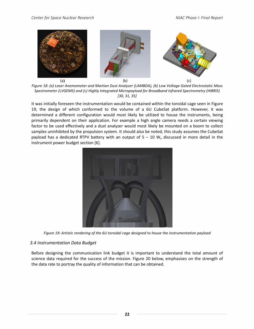
(a) (b) (c) Figure 18: (a) Laser Anemometer and Martian Dust Analyzer (LAMBDA), (b) Low Voltage Gated Electrostatic Mass
Spectrometer (LVGEMS) and (c) Highly Integrated Micropayload for Broadband Infrared Spectrometry (HIBRIS) [30, 31, 35]
It was initially foreseen the instrumentation would be contained within the toroidal cage seen in Figure 19, the design of which conformed to the volume of a 6U CubeSat platform. However, it was determined a different configuration would most likely be utilized to house the instruments, being primarily dependent on their application. For example a high angle camera needs a certain viewing factor to be used effectively and a dust analyzer would most likely be mounted on a boom to collect samples uninhibited by the propulsion system. It should also be noted, this study assumes the CubeSat payload has a dedicated RTPV battery with an output of 5 – 10 We discussed in more detail in the instrument power budget section [6].
Figure 19: Artistic rendering of the 6U toroidal cage designed to house the instrumentation payload
3.4 Instrumentation Data Budget
Before designing the communication link budget it is important to understand the total amount of science data required for the success of the mission. Figure 20 below, emphasizes on the strength of the data rate to portray the quality of information that can be obtained.
Center for Space Nuclear Research NIAC Phase I: Final Report
23
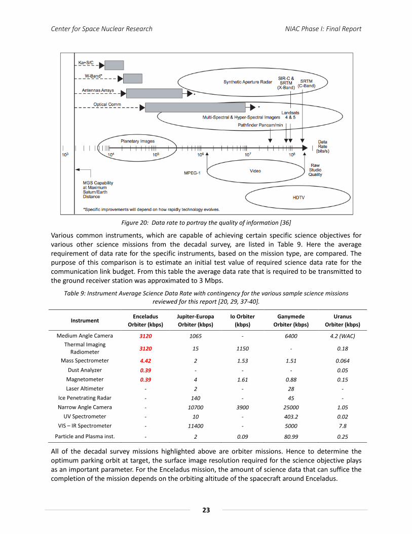
Figure 20: Data rate to portray the quality of information [36]
Various common instruments, which are capable of achieving certain specific science objectives for various other science missions from the decadal survey, are listed in Table 9. Here the average requirement of data rate for the specific instruments, based on the mission type, are compared. The purpose of this comparison is to estimate an initial test value of required science data rate for the communication link budget. From this table the average data rate that is required to be transmitted to the ground receiver station was approximated to 3 Mbps.
Table 9: Instrument Average Science Data Rate with contingency for the various sample science missions reviewed for this report [20, 29, 37-40].
Instrument Enceladus
Orbiter (kbps) Jupiter-Europa Orbiter (kbps)
Io Orbiter (kbps)
Ganymede Orbiter (kbps)
Uranus Orbiter (kbps)
Medium Angle Camera 3120 1065 - 6400 4.2 (WAC) Thermal Imaging
Radiometer 3120 15 1150 - 0.18
Mass Spectrometer 4.42 2 1.53 1.51 0.064 Dust Analyzer 0.39 - - - 0.05
Magnetometer 0.39 4 1.61 0.88 0.15 Laser Altimeter - 2 - 28 -
Ice Penetrating Radar - 140 - 45 - Narrow Angle Camera - 10700 3900 25000 1.05
UV Spectrometer - 10 - 403.2 0.02 VIS – IR Spectrometer - 11400 - 5000 7.8
Particle and Plasma inst. - 2 0.09 80.99 0.25
All of the decadal survey missions highlighted above are orbiter missions. Hence to determine the optimum parking orbit at target, the surface image resolution required for the science objective plays as an important parameter. For the Enceladus mission, the amount of science data that can suffice the completion of the mission depends on the orbiting altitude of the spacecraft around Enceladus.

Center for Space Nuclear Research NIAC Phase I: Final Report
24
The following plots show the essential limiting factors of the concept of operations of the mission. The parking orbit needs to be optimized in order to perform sufficient science, to meet the objectives and be able to send the data back within a reasonable time. Longer duration may implies the need for a longer mission lifetime and possibly more radiation shielding of the system. Figure 21 below shows a plot of parking orbit altitude (km) versus the average number of pictures required to complete the science objective. Additionally, Figure 22 shows a plot of ground image area (m2) that can be imaged compared to the parking orbit altitude (km)
Figure 21: Parking orbit altitude versus picture count
Figure 23 below shows the RF communication downlink transmission time (hours) required in order to accomplish the image science objective and is based on the parking orbit altitude (km). Because of the image size (meter/pixel) difference at varying parking orbits the total transmission time needed in order to complete the image objectives increases exponentially. Thus, parking orbit can ultimately determine the mission lifetime needs for the architecture.
Figure 22: Ground image area versus parking orbit altitude

Center for Space Nuclear Research NIAC Phase I: Final Report
25
Table A-1 in Appendix A shows the tabulation used in obtaining the optimized parking orbit and observation/measurement period, for the required image resolution. From the table it is found the optimal parking orbit altitude required to accomplish the bulk of the mission (only imagery) is approximately 121.875 km. Also the total number of pictures required from this table is 124 pictures. Now since the resolutions of these pictures are very high, each picture is averaged to weigh 20 Mb in size. Now if the data rate is 1 Mbps, for a 5 minute communication window, the total data that can be transmitted back is 300 Mb, which is equal to sending 15 pictures. Hence for just sending a good quality, 15 m/pixel, image size it will take approximately 9 – 10 days. But certain science objectives such as studying the physical conditions at the plume source would require 2 m/pixel image size. In that case the total number of pictures required is approximately 6,964. Hence for all that data to be transmitted at 1 Mbps over 5 minutes in almost every other earth day will extend the mission duration to 465 days. Thus, for a 3 Mbps data rate this duration drops to 155 days of mission duration, which is still a very lengthy mission.
Figure 23: RF communication downlink transmission time (hours) versus parking orbit altitude (km)
It is important to note that the mission length mentioned above on just the basis of the camera imagery serves the length for data dumped from one instrument only. There will be data generated from other instruments as well. Hence it was concluded that a reasonable scientific data transfer rate required for to complete the mission would be 3 Mbps. Also it’s worth noting this is the same data rate averaged from the comparison of the other decadal survey missions from Table 9 mentioned earlier. Therefore the communication system designed for this mission can potentially service other decadal survey missions as well.
An extended justification of the required 3 Mbps data rate has also been attempted by showing an operational model of the various payload instruments of the spacecraft. The objective behind this model is to allot the operation time of each subsystem in order to achieve the science data and keep the mission alive. Table 10 below, shows the data budget extracted from the operations model.
Center for Space Nuclear Research NIAC Phase I: Final Report
26
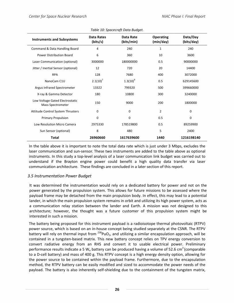
Table 10: Spacecraft Data Budget.
Instruments and Subsystems Data Rates (bits/s)
Data Rate (bits/min)
Operating (min/day)
Data/Day (bits/day)
Command & Data Handling Board 4 240 1 240
Power Distribution Board 6 360 10 3600
Laser Communication (optional) 3000000 180000000 0.5 90000000
Jitter / Inertial Sensor (optional) 12 720 20 14400
RPA 128 7680 400 3072000
NanoCam C1U 2.1(10)7 1.3(10)9 0.5 629145600
Argus Infrared Spectrometer 13322 799320 500 399660000
X-ray & Gamma Detector 180 10800 300 3240000
Low Voltage Gated Electrostatic Mass Spectrometer 150 9000 200 1800000
Attitude Control System Thrusters 0 0 2 0
Primary Propulsion 0 0 0.5 0
Low Resolution Micro Camera 2975330 178519800 0.5 89259900
Sun Sensor (optional) 8 480 5 2400
Total 26960660 1617639600 1440 1216198140
In the table above it is important to note the total data rate which is just under 3 Mbps, excludes the laser communication and sun-sensor. These two instruments are added to the table above as optional instruments. In this study a top-level analysis of a laser communication link budget was carried out to understand if the Brayton engine power could benefit a high quality data transfer via laser communication architecture. These findings are concluded in a later section of this report.
3.5 Instrumentation Power Budget
It was determined the instrumentation would rely on a dedicated battery for power and not on the power generated by the propulsion system. This allows for future missions to be assessed where the payload frame may be detached from the main propulsion body. In effect, this may lead to a potential lander, in which the main propulsion system remains in orbit and utilizing its high power system, acts as a communication relay station between the lander and Earth. A mission was not designed to this architecture; however, the thought was a future customer of this propulsion system might be interested in such a mission.
The battery being proposed for this instrument payload is a radioisotope thermal photovoltaic (RTPV) power source, which is based on an in-house concept being studied separately at the CSNR. The RTPV battery will rely on thermal input from 238PuO2, and utilizing a similar encapsulation approach, will be contained in a tungsten-based matrix. This new battery concept relies on TPV energy conversion to convert radiative energy from an RHS and convert it to usable electrical power. Preliminary performance results indicate a 5 We battery can be produced having a volume of 52.6 cm3 (comparable to a D-cell battery) and mass of 400 g. This RTPV concept is a high energy density option, allowing for the power source to be contained within the payload frame. Furthermore, due to the encapsulation method, the RTPV battery can be easily modified and sized to accommodate the power needs of the payload. The battery is also inherently self-shielding due to the containment of the tungsten matrix,

Center for Space Nuclear Research NIAC Phase I: Final Report
27
preventing degradation to on-board electronics. The power budget for the instrumentation package is tabulated in Table 11.
Table 11: Payload Power Budget
Instruments and Subsystems Max Power (W)
Operation (min/day)
Command & Data Handling Board 1 1
Power Distribution Board 0.25 10
Laser Communication (optional) 500 0.5
Jitter / Inertial Sensor (optional) 0.2 20
RPA 0.5 400
NanoCam C1U 0.66 0.5
Argus Infrared Spectrometer 2.635 500
X-ray & Gamma Detector 2.5 300
Low Voltage Gated Electrostatic Mass
Spectrometer 0.5 200
Attitude Control System Thrusters 0.5 2
Guidance, Navigation and control
sensors 4 0.5
Low Resolution Micro Camera 0.198 0.5
Sun Sensor (optional) 3.4 5
Total 13.023 1440
Again the laser communication, jitter sensor and the sun sensor are all optional in the table shown above and the total power required continously for the scientific operation of the spacecraft payload is approximately 13 W. Hence 3 RTPVs with an electrical power output of 15 W will suffice.
The average daily power mode usage is shown in the pie chart (Figure 24) below. The pie chart is a visual extraction of the table above showing the comparison of the power required by the individual sub-systems and instruments of the payload platform. The chart incorporates the power distribution during active imagery operational mode.
3.6 Propulsion Systems
The operational modes of the system were already previously described and the thermal propulsion mode was already introduced. The idea of the concept, providing power and propulsion when needed through the mission lends the overall system to being highly functional. Described in greater detail here are the two propulsion modes being proposed for the system – thermal propulsion and electrical propulsion. Thermal propulsion in general provides high thrust at a moderate Isp, which is useful for orbital maneuvering, such as escaping Earth or capturing at Saturn. For this concept, it is believed by employing a high thrust system; a scenario such as escaping from Earth can be completed more quickly than say electrical propulsion alone. The secondary propulsion system being used is electrical propulsion, which has a high Isp for efficient interplanetary travel. The functionality of electrical propulsion will be conducted from electrical power generated by the energy conversion system. And by employing electrical propulsion, continual thrusting can be performed in transit to Saturn, which takes

Center for Space Nuclear Research NIAC Phase I: Final Report
28
a portion of the ΔV burden from the thermal propulsion system to reach the Saturnian system. This in turn, minimizes the propellant mass needed for the thermal propulsion mode, which is the largest mass of the system.
Figure 24: Average daily power mode usage in minutes.
In this study the proposed propulsion system will propel itself from a geocentric orbit using phasing maneuvers, i.e., periapsis pumping. This is accomplished by pulsing the thermal propulsion system at the periapsis to induce apogee raising until transition into the correct heliocentric orbit for the interplanetary phase can be achieved. Error! Reference source not found.Figure 25 shows an illustration of phasing maneuver trajectories using periapsis pumping. This technique of orbital escape aligns well with the RTR concept, where propellant is injected into the thermal capacitor and out of the nozzle and the thermal capacitor is then allowed to “recharge” through each orbit. Additionally, by employing a thermal propulsion mode, launch mass is minimized by negating the need for an upper stage motor. Once a heliocentric orbit is achieved the electrical mode will be employed under the closed loop Brayton cycle powering either the communication or electric propulsion systems. Utilizing the high efficiency of electric propulsion through the interplanetary phase will aid in decreasing overall transit times.
Figure 25: Orbital escape process utilizing the dual-mode system [41].

Center for Space Nuclear Research NIAC Phase I: Final Report
29
The plan to use this phasing maneuver to escape the gravitational pull of earth led to calculations based on the energy content of the core, the amount of thrust available per blowdown, and which propellants would be optimal for time, mass, and volume. The governing equation used was the rocket equation, given below:
𝑀𝑓𝑖𝑛𝑎𝑙
𝑀𝑖𝑛𝑖𝑡𝑖𝑎𝑙= 𝑒(−∆𝑉𝑉𝑒𝑥
)
where Mfinal is the mass of the craft after the propellant has been ejected, Minitial is the mass of the craft before the propellant is used, ∆V is the change in velocity, and Vex is the exit velocity of the propellant from the nozzle.
The exit velocity is related to the specific impulse (Isp) of the system by the equation below:
𝐼𝑠𝑝 = 𝑉𝑒𝑥/9.81
The Isp of a system is a characteristic of the propellant used and the temperature at which it is exhausted. The initial choice for propellant for the thermal propulsion mode is hydrogen due to its higher Isp and typical use in this application. To calculate the Isp for the RTR system, Isp measurements from the NERVA program were scaled according to the atomic mass of the fuel and the differences in operational temperatures. The relation to the NERVA program was done because both systems are strictly thermal propulsion-based and employs hydrogen as propellant. The NERVA program was the development of a nuclear thermal rocket (NTR) and used molecular hydrogen as a propellant at 2550 K and the Peewee engine measured an Isp of ~850 s. Those values were scaled by the ratio of the roots of the temperatures and the inverse of the square of the mass. This resulted in the equation below:
𝐼𝑠𝑝 = 850 ∗√𝑇
√2550∗
1√𝑚
where T is the temperature of the exhaust from the core and m is the atomic mass of the propellant.
By using these equations, a value for ∆V could be found for each burn, based on the fuel used and the temperature of the core. It was determined; the greatest mass of the system was the amount of propellant needed to achieve Earth escape. Thus, it was determined thermal propulsion was to provide the minimum ΔV needed to achieve escape. Therefore, in this study the total ΔV required by the thermal propulsion mode to achieve Earth escape was set to 3.2 km/s. Additionally, total masses and volumes for those propellants could be found to ensure the system would meet the requirements for the launch vehicle. When using molecular hydrogen for the propellant, each burn provided 0.016 km/s ∆V. If hydrogen was used for the entirety of the escape the total hydrogen mass that would be required is 375 kg. Figure 26 shows the system concept with a single hydrogen tank. The final system size is 4.88 m tall and 1.58 m in diameter. For reference the stick person measures 1.83 m (6 ft) tall. In relying completely on hydrogen propellant for the thermal propulsion system the question in terms of potential launch vehicle transforms from being – are we mass constrained? to being – are we volume constrained? within the launch vehicle fairing.
Relying completely on hydrogen propellant to achieve Earth escape presented another challenge. Through the perigee pumping scenario the orbit becomes more and more elliptical and from the ΔV achieved through each burn it was determined the final orbit would have a maximum distance from earth of 2.0x10⁷ km and would take 3,640 days (~10 years) to complete. This final orbit may be problematic in achieving a reasonable transit time, thus an evaluation was conducted to find solutions to overcome a long final orbit. One possible solution was to use an alternate fuel for the final perigee burn to achieve the ΔV needed to escape Earth, avoiding a long final orbit. Due to the nature of the fuels, propellants with heavier atomic masses provide a larger ∆V per burn, but have lower Isp values,
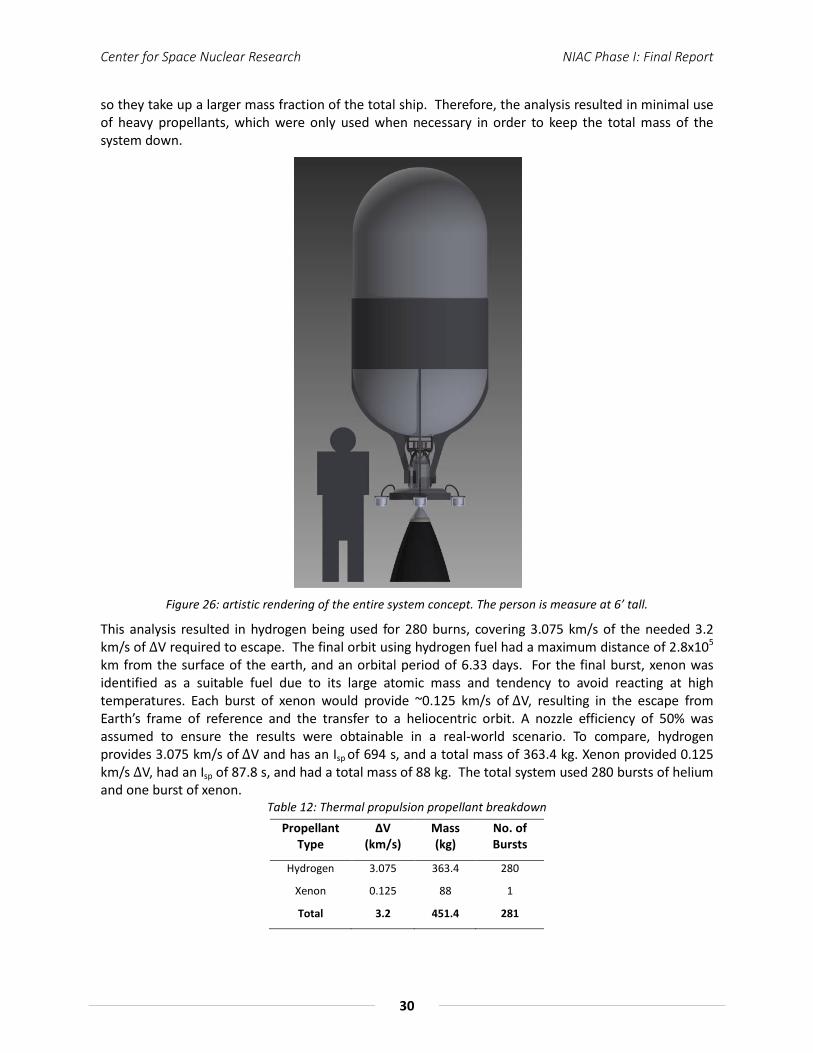
Center for Space Nuclear Research NIAC Phase I: Final Report
30
so they take up a larger mass fraction of the total ship. Therefore, the analysis resulted in minimal use of heavy propellants, which were only used when necessary in order to keep the total mass of the system down.
Figure 26: artistic rendering of the entire system concept. The person is measure at 6’ tall.
This analysis resulted in hydrogen being used for 280 burns, covering 3.075 km/s of the needed 3.2 km/s of ∆V required to escape. The final orbit using hydrogen fuel had a maximum distance of 2.8x10⁵ km from the surface of the earth, and an orbital period of 6.33 days. For the final burst, xenon was identified as a suitable fuel due to its large atomic mass and tendency to avoid reacting at high temperatures. Each burst of xenon would provide ~0.125 km/s of ∆V, resulting in the escape from Earth’s frame of reference and the transfer to a heliocentric orbit. A nozzle efficiency of 50% was assumed to ensure the results were obtainable in a real-world scenario. To compare, hydrogen provides 3.075 km/s of ∆V and has an Isp of 694 s, and a total mass of 363.4 kg. Xenon provided 0.125 km/s ∆V, had an Isp of 87.8 s, and had a total mass of 88 kg. The total system used 280 bursts of helium and one burst of xenon.
Table 12: Thermal propulsion propellant breakdown Propellant
Type ∆V
(km/s) Mass (kg)
No. of Bursts
Hydrogen 3.075 363.4 280
Xenon 0.125 88 1
Total 3.2 451.4 281

Center for Space Nuclear Research NIAC Phase I: Final Report
31
Because of the propellant mass and volume of hydrogen an analysis of other methods to achieve Earth escape were briefly explored. Solid rocket motors were considered for use in achieving Earth escape, given their high thrust. The use of a small solid rocket motor could replace the need of xenon for the final burst, or a large solid rocket motor could be used to achieve Earth escape in a single burn. The thought is the system wouldn’t be negated and would still need the thermal propulsion mode for Saturn capture, and the electrical production mode for electrical propulsion and communication. Instead, a single solid kick motor could replace the large hydrogen tank allowing the system to better fit within a smaller launch vehicle fairing and would simplify the Earth escape procedure. However, the use of a chemical system may add exorbitant costs to the mission compared to a hydrogen propellant system. More analysis in alternatives to the thermal propulsion system will need to be further reviewed, but this study focused on an analysis of the thermal mode.
Figure 27 shows a graphical rendering of the propulsion system operating in LEO. The primary hydrogen propellant tank dominates the mass of the system through the Earth escape phase. It is assumed once to system achieves escape from the Earth frame of reference, the primary propellant tank would be jettisoned from the system. Secondary propellant tanks (not pictured) would then be used to operate the thermal propulsion system once the Saturnian system is reached. Finally once Enceladus orbit is achieved all remaining thermal propulsion tankage will be jettisoned to complete the science objectives.
Figure 27: an artistic rendering of the propulsions system concept in LEO
Based on the performance of the system a nozzle analysis was performed for use with hydrogen propellant. Table 13 shows the data used for hydrogen where Figure 28 shows the analysis technique and the nozzle dimensions are given in Table 14.
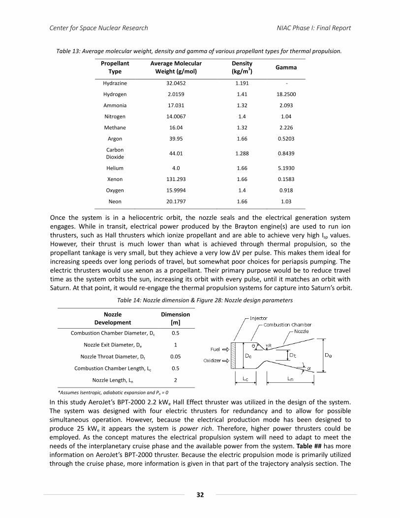
Center for Space Nuclear Research NIAC Phase I: Final Report
32
Table 13: Average molecular weight, density and gamma of various propellant types for thermal propulsion.
Propellant Type
Average Molecular Weight (g/mol)
Density 3)(kg/m Gamma
Hydrazine 32.0452 1.191 -
Hydrogen 2.0159 1.41 18.2500
Ammonia 17.031 1.32 2.093
Nitrogen 14.0067 1.4 1.04
Methane 16.04 1.32 2.226
Argon 39.95 1.66 0.5203
Carbon Dioxide 44.01 1.288 0.8439
Helium 4.0 1.66 5.1930
Xenon 131.293 1.66 0.1583
Oxygen 15.9994 1.4 0.918
Neon 20.1797 1.66 1.03
Once the system is in a heliocentric orbit, the nozzle seals and the electrical generation system engages. While in transit, electrical power produced by the Brayton engine(s) are used to run ion thrusters, such as Hall thrusters which ionize propellant and are able to achieve very high Isp values. However, their thrust is much lower than what is achieved through thermal propulsion, so the propellant tankage is very small, but they achieve a very low ∆V per pulse. This makes them ideal for increasing speeds over long periods of travel, but somewhat poor choices for periapsis pumping. The electric thrusters would use xenon as a propellant. Their primary purpose would be to reduce travel time as the system orbits the sun, increasing its orbit with every pulse, until it matches an orbit with Saturn. At that point, it would re-engage the thermal propulsion systems for capture into Saturn’s orbit.
Table 14: Nozzle dimension & Figure 28: Nozzle design parameters
Nozzle Development
Dimension [m]
Combustion Chamber Diameter, Dc 0.5
Nozzle Exit Diameter, De 1
Nozzle Throat Diameter, Dt 0.05
Combustion Chamber Length, Lc 0.5
Nozzle Length, Ln
*Assumes Isentropic, adiabatic expansion and Pa
2
= 0
In this study AeroJet’s BPT-2000 2.2 kWe Hall Effect thruster was utilized in the design of the system. The system was designed with four electric thrusters for redundancy and to allow for possible simultaneous operation. However, because the electrical production mode has been designed to produce 25 kWe it appears the system is power rich. Therefore, higher power thrusters could be employed. As the concept matures the electrical propulsion system will need to adapt to meet the needs of the interplanetary cruise phase and the available power from the system. Table ## has more information on AeroJet’s BPT-2000 thruster. Because the electric propulsion mode is primarily utilized through the cruise phase, more information is given in that part of the trajectory analysis section. The

Center for Space Nuclear Research NIAC Phase I: Final Report
33
amount of propellant required for the electric propulsion system for the cruise phase is discussed in the trajectory section.
Table 15: AeroJet BPT-2000 Hall Effect thruster [42]
Design Characteristics Performance at 2.2 kW
Propellant Xenon Thrust 123 mN
Mass <5.2 kg Isp 1765 sec
Envelope Dim. 15 x 17 x 22 cm Life (cont.) >6000 HR
Nominal Input Power 2200 W On/Off Cycles 6000 cycles
3.7 Trajectory Analysis
The trajectory analysis of a mission architecture serves as a crucial step to determine the feasibility of both the mission and the primary technology used for it. To determine the trajectories an in-house built trajectory generator code was used for optimizing the trajectory. The optimization model used in this code is rudimentary and requires continued polishing provided additional time available. Also, for future work to verify trajectory results, the implementation of the trajectory generator software tool Evolutionary Mission Trajectory Generator (EMTG) developed at NASA Goddard or a similar tool will be done. Specifically, EMTG implements a variety of numerical methods, mainly using evolutionary algorithms to optimize a trajectory based on hierarchy of factors such as ΔV, time of flight, number of journeys, etc.
The mission profile was developed into two phases: (1) the interplanetary cruise phase where the system progresses from Earth orbit to capture at Saturn and (2) the Saturn – Enceladus transfer orbit phase. In the analysis presented for the cruise phase, gravity assists are implemented to further lower mass needs of the system, although future assessment of non-gravity assist trajectories may be performed to alleviate strict launch windows. In the transfer to Enceladus a trajectory was assessed, which includes numerous engineering and science-based flybys of several Saturnian satellites. This phase of the mission can be complex and more work in its evaluation must be conducted. Overall, the trajectory optimization is in now ways exhaustive and more work will be needed as the concept & mission design is matured.
3.7.1 Interplanetary Cruise Phase
Using the in-house code, trajectory results were produced as a baseline for communications, radiation and operations calculations. Figure 29 shows the X-Y projection of the Earth – Saturn Cruise phase trajectory where the x-axis and y-axis are in AU. The three black ellipses represent the heliocentric orbits of Earth, Jupiter and Saturn, from smallest to largest respectively. The yellow spot in the middle represents the Sun. The red trajectories are the Earth flybys, the green trajectory is the Venus flyby and the blue trajectory is the transfer trajectory to Saturn orbit insertion. Table 16 lists the important dates and the ΔV’s found using the trajectory code.
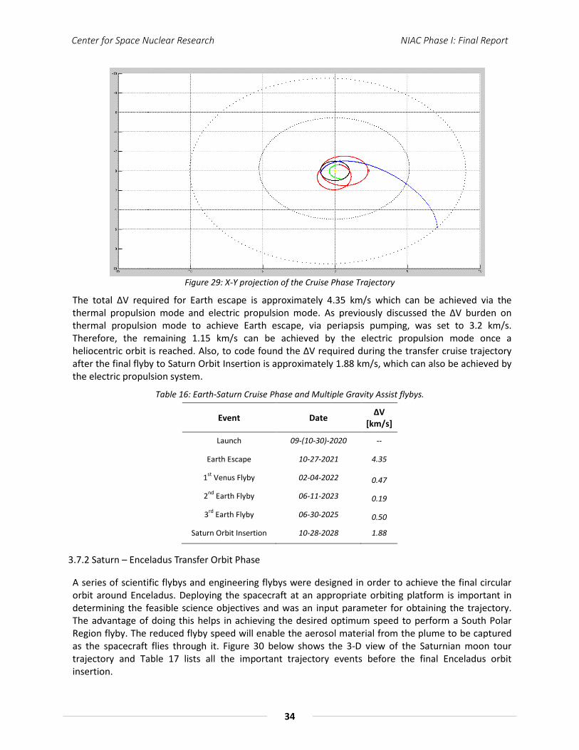
Center for Space Nuclear Research NIAC Phase I: Final Report
34
Figure 29: X-Y projection of the Cruise Phase Trajectory
The total ΔV required for Earth escape is approximately 4.35 km/s which can be achieved via the thermal propulsion mode and electric propulsion mode. As previously discussed the ΔV burden on thermal propulsion mode to achieve Earth escape, via periapsis pumping, was set to 3.2 km/s. Therefore, the remaining 1.15 km/s can be achieved by the electric propulsion mode once a heliocentric orbit is reached. Also, to code found the ΔV required during the transfer cruise trajectory after the final flyby to Saturn Orbit Insertion is approximately 1.88 km/s, which can also be achieved by the electric propulsion system.
Table 16: Earth-Saturn Cruise Phase and Multiple Gravity Assist flybys.
Event Date ΔV [km/s]
Launch 09-(10-30)-2020 --
Earth Escape 10-27-2021 4.35
1st Venus Flyby 02-04-2022 0.47
2nd Earth Flyby 06-11-2023 0.19
3rd Earth Flyby 06-30-2025 0.50
Saturn Orbit Insertion 10-28-2028 1.88
3.7.2 Saturn – Enceladus Transfer Orbit Phase
A series of scientific flybys and engineering flybys were designed in order to achieve the final circular orbit around Enceladus. Deploying the spacecraft at an appropriate orbiting platform is important in determining the feasible science objectives and was an input parameter for obtaining the trajectory. The advantage of doing this helps in achieving the desired optimum speed to perform a South Polar Region flyby. The reduced flyby speed will enable the aerosol material from the plume to be captured as the spacecraft flies through it. Figure 30 below shows the 3-D view of the Saturnian moon tour trajectory and Table 17 lists all the important trajectory events before the final Enceladus orbit insertion.
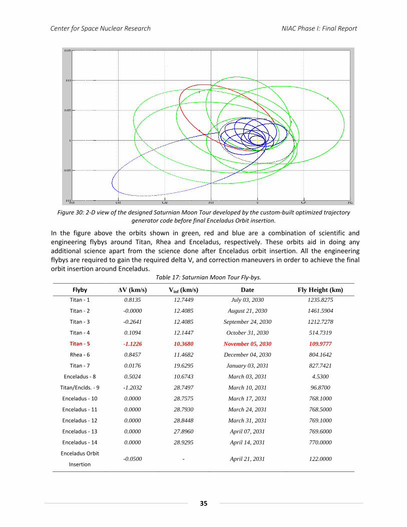
Center for Space Nuclear Research NIAC Phase I: Final Report
35
Figure 30: 2-D view of the designed Saturnian Moon Tour developed by the custom-built optimized trajectory
generator code before final Enceladus Orbit insertion.
In the figure above the orbits shown in green, red and blue are a combination of scientific and engineering flybys around Titan, Rhea and Enceladus, respectively. These orbits aid in doing any additional science apart from the science done after Enceladus orbit insertion. All the engineering flybys are required to gain the required delta V, and correction maneuvers in order to achieve the final orbit insertion around Enceladus.
Table 17: Saturnian Moon Tour Fly-bys.
Flyby ΔV (km/s) Vinf (km/s) Date Fly Height (km) Titan - 1 0.8135 12.7449 July 03, 2030 1235.8275
Titan - 2 -0.0000 12.4085 August 21, 2030 1461.5904
Titan - 3 -0.2641 12.4085 September 24, 2030 1212.7278
Titan - 4 0.1094 12.1447 October 31, 2030 514.7319
Titan - 5 -1.1226 10.3680 November 05, 2030 109.9777
Rhea - 6 0.8457 11.4682 December 04, 2030 804.1642
Titan - 7 0.0176 19.6295 January 03, 2031 827.7421
Enceladus - 8 0.5024 10.6743 March 03, 2031 4.5300
Titan/Enclds. - 9 -1.2032 28.7497 March 10, 2031 96.8700
Enceladus - 10 0.0000 28.7575 March 17, 2031 768.1000
Enceladus - 11 0.0000 28.7930 March 24, 2031 768.5000
Enceladus - 12 0.0000 28.8448 March 31, 2031 769.1000
Enceladus - 13 0.0000 27.8960 April 07, 2031 769.6000
Enceladus - 14 0.0000 28.9295 April 14, 2031 770.0000
Enceladus Orbit
Insertion -0.0500 - April 21, 2031 122.0000
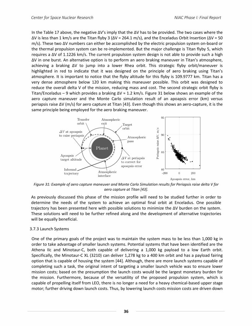
Center for Space Nuclear Research NIAC Phase I: Final Report
36
In the Table 17 above, the negative ΔV’s imply that the ΔV has to be provided. The two cases where the ΔV is less than 1 km/s are the Titan flyby 3 (ΔV = 264.1 m/s), and the Enceladus Orbit Insertion (ΔV = 50 m/s). These two ΔV numbers can either be accomplished by the electric propulsion system on-board or the thermal propulsion system can be re-implemented. But the major challenge is Titan flyby 5, which requires a ΔV of 1.1226 km/s. The current propulsion system design is not able to provide such a high ΔV in one burst. An alternative option is to perform an aero braking maneuver in Titan’s atmosphere, achieving a braking ΔV to jump into a lower Rhea orbit. This strategic flyby orbit/maneuver is highlighted in red to indicate that it was designed on the principle of aero braking using Titan’s atmosphere. It is important to notice that the flyby altitude for this flyby is 109.9777 km. Titan has a very dense atmosphere below 120 km making this maneuver possible. This orbit was designed to reduce the overall delta V of the mission, reducing mass and cost. The second strategic orbit flyby is Titan/Enceladus – 9 which provides a braking ΔV ≈ 1.2 km/s. Figure 31 below shows an example of the aero capture maneuver and the Monte Carlo simulation result of an apoapsis error (km) versus periapsis raise ΔV (m/s) for aero capture at Titan [43]. Even though this shows an aero-capture, it is the same principle being employed for the aero braking maneuver.
Figure 31: Example of aero capture maneuver and Monte Carlo Simulation results for Periapsis raise delta V for
aero capture at Titan [43].
As previously discussed this phase of the mission profile will need to be studied further in order to determine the needs of the system to achieve an optimal final orbit at Enceladus. One possible trajectory has been presented here with possible solutions to minimize the ΔV burden on the system. These solutions will need to be further refined along and the development of alternative trajectories will be equally beneficial.
3.7.3 Launch Systems
One of the primary goals of the project was to maintain the system mass to be less than 1,000 kg in order to take advantage of smaller launch systems. Potential systems that have been identified are the Athena IIc and Minotaur-C, both capable of delivering a 1,000 kg payload to a low Earth orbit. Specifically, the Minotaur-C XL (3210) can deliver 1,278 kg to a 400 km orbit and has a payload fairing option that is capable of housing the system [44]. Although, there are more launch systems capable of completing such a task, the original intent of targeting a smaller launch vehicle was to ensure lower mission costs; based on the presumption the launch costs would be the largest monetary burden for the mission. Furthermore, because of the versatility of the proposed propulsion system, which is capable of propelling itself from LEO, there is no longer a need for a heavy chemical-based upper stage motor; further driving down launch costs. Thus, by lowering launch costs mission costs are driven down
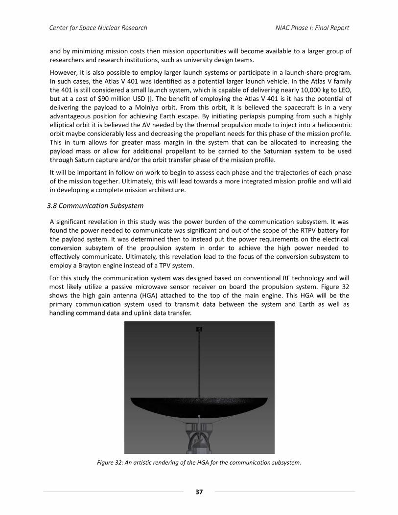
Center for Space Nuclear Research NIAC Phase I: Final Report
37
and by minimizing mission costs then mission opportunities will become available to a larger group of researchers and research institutions, such as university design teams.
However, it is also possible to employ larger launch systems or participate in a launch-share program. In such cases, the Atlas V 401 was identified as a potential larger launch vehicle. In the Atlas V family the 401 is still considered a small launch system, which is capable of delivering nearly 10,000 kg to LEO, but at a cost of $90 million USD []. The benefit of employing the Atlas V 401 is it has the potential of delivering the payload to a Molniya orbit. From this orbit, it is believed the spacecraft is in a very advantageous position for achieving Earth escape. By initiating periapsis pumping from such a highly elliptical orbit it is believed the ΔV needed by the thermal propulsion mode to inject into a heliocentric orbit maybe considerably less and decreasing the propellant needs for this phase of the mission profile. This in turn allows for greater mass margin in the system that can be allocated to increasing the payload mass or allow for additional propellant to be carried to the Saturnian system to be used through Saturn capture and/or the orbit transfer phase of the mission profile.
It will be important in follow on work to begin to assess each phase and the trajectories of each phase of the mission together. Ultimately, this will lead towards a more integrated mission profile and will aid in developing a complete mission architecture.
3.8 Communication Subsystem
A significant revelation in this study was the power burden of the communication subsystem. It was found the power needed to communicate was significant and out of the scope of the RTPV battery for the payload system. It was determined then to instead put the power requirements on the electrical conversion subsytem of the propulsion system in order to achieve the high power needed to effectively communicate. Ultimately, this revelation lead to the focus of the conversion subsystem to employ a Brayton engine instead of a TPV system.
For this study the communication system was designed based on conventional RF technology and will most likely utilize a passive microwave sensor receiver on board the propulsion system. Figure 32 shows the high gain antenna (HGA) attached to the top of the main engine. This HGA will be the primary communication system used to transmit data between the system and Earth as well as handling command data and uplink data transfer.
Figure 32: An artistic rendering of the HGA for the communication subsystem.
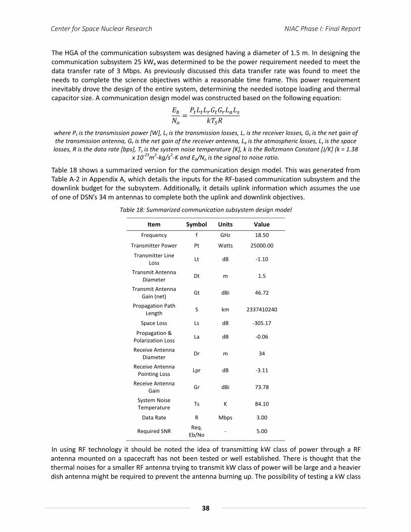
Center for Space Nuclear Research NIAC Phase I: Final Report
38
The HGA of the communication subsystem was designed having a diameter of 1.5 m. In designing the communication subsystem 25 kWe was determined to be the power requirement needed to meet the data transfer rate of 3 Mbps. As previously discussed this data transfer rate was found to meet the needs to complete the science objectives within a reasonable time frame. This power requirement inevitably drove the design of the entire system, determining the needed isotope loading and thermal capacitor size. A communication design model was constructed based on the following equation:
𝐸𝑏𝑁𝑜
=𝑃𝑡𝐿𝑡𝐿𝑟𝐺𝑡𝐺𝑟𝐿𝑎𝐿𝑠
𝑘𝑇𝑆𝑅
where Pt is the transmission power [W], Lt is the transmission losses, Lr is the receiver losses, Gt is the net gain of the transmission antenna, Gr is the net gain of the receiver antenna, La is the atmospheric losses, Ls is the space
losses, R is the data rate [bps], Ts is the system noise temperature [K], k is the Boltzmann Constant [J/K] (k = 1.38 x 10⁻²³m2-kg/s2-K and Eb/No is the signal to noise ratio.
Table 18 shows a summarized version for the communication design model. This was generated from Table A-2 in Appendix A, which details the inputs for the RF-based communication subsystem and the downlink budget for the subsystem. Additionally, it details uplink information which assumes the use of one of DSN’s 34 m antennas to complete both the uplink and downlink objectives.
Table 18: Summarized communication subsystem design model
Item Symbol Units Value Frequency f GHz 18.50
Transmitter Power Pt Watts 25000.00
Transmitter Line Loss Lt dB -1.10
Transmit Antenna Diameter Dt m 1.5
Transmit Antenna Gain (net) Gt dBi 46.72
Propagation Path Length S km 2337410240
Space Loss Ls dB -305.17
Propagation & Polarization Loss La dB -0.06
Receive Antenna Diameter Dr m 34
Receive Antenna Pointing Loss Lpr dB -3.11
Receive Antenna Gain Gr dBi 73.78
System Noise Temperature Ts K 84.10
Data Rate R Mbps 3.00
Required SNR Req. Eb/No - 5.00
In using RF technology it should be noted the idea of transmitting kW class of power through a RF antenna mounted on a spacecraft has not been tested or well established. There is thought that the thermal noises for a smaller RF antenna trying to transmit kW class of power will be large and a heavier dish antenna might be required to prevent the antenna burning up. The possibility of testing a kW class

Center for Space Nuclear Research NIAC Phase I: Final Report
39
microwave power transmission is being planned by JAXA in conjunction with NASA. The plan for the experiment is to mount a 200 kg communication that will attempt to transmit a 3.8 kWe power beam. With such projects currently in progress, there is a high possibility that in the future smaller and lighter RF antennas will be able to handle high transmission power. Thus, a system that can provide 25 kWe power for communication may be a very promising game changing technology of the future.
Employing 25 kWe of power to the communication subsystem may pose a significant challenge, which will need to be addressed in continued work. One thought is to evaluate lower download rates, which will in effect decrease the power needs of the communication subsystem. Furthermore, as the system is being further matured, the communication system will need to also be re-evaluated with a broader assessment of download rates, power requirements and antenna size. Additionally, the use of other communication technologies may provide an alternative to the RF-based system designed for this concept. One promising communication technology is laser-based communication and recent successes seen from NASA’s LADEE has shown the viability of laser communication and the capability of achieving large data transfer rates through its use. Laser communication was not thoroughly evaluated in this study, but one advantage of laser communication over RF communication is laser transmitters can achieve very low beam width angles for a signal transmission compared to RF transmitters. This implies that the directive gain that can be obtained is very high. Figure 33 illustrates beam spread differences between RF- and laser-based systems. Also, potentially kW class of power can be easily transmitted through a laser communication channel.
Figure 33: Comparison of RF and optical beam spreads from Saturn [36].
Ultimately, the communication subsystem will be further refined as the concept is further developed and based on recent advances on laser-based communication systems it is only appropriate to include a design analysis of a comparable laser-based communication system. There is thought that the power requirements of a laser-based system may be significantly less than that required by a traditional RF system. If that’s the case, then system might be able to utilize just TPV conversion to provide the necessary electrical power to operated the communication system.

Center for Space Nuclear Research NIAC Phase I: Final Report
40
4.0 Future Work
The primary goal of this study was to flesh out the initial concept of a radioisotope-based propulsion system for small payloads. The design of which was performed in the context of delivering a 6U payload to the orbit of Enceladus. Building on the work completed here the system concept will need to be further matured as its design is further optimized.
Modeling of the thermal capacitor core, using programs such as COMSOL Multiphysics, will need to become more integrated to fully determine the thermal interactions of the various central components of the core including the thermal capacitor, insulation layers, support structures, etc and their interactions with one another. Additionally, as design changes occur through the evolution of this concept, modeling will need to be used to address those changes as well. Optimization of the core design will need to be continued, progressing to the inclusion of an appropriate containment method for a PCM thermal capacitor. Research on silicon will need to be continued and experiments will need to be conducted, cycling silicon through its liquid-to-solid phase change in order to determine potential stresses on the system. Additionally, methods to alleviate potential stresses and ensuring thermal conductive pathways between a PCM thermal capacitor and flow channels are maintained will need to be further evaluated. Proper understanding and functionality of the thermal capacitor is key to the development of this concept and Figure 34 shows details of the CSNR’s remote laser heating apparatus that can be used to better understand silicon’s phase change process.
(a) (b)
Figure 34: (a) Shows the inner chamber of CSNR’s remote laser heating apparatus with a test article within and (b) shows the P&ID of the laser heating test facility.
Follow on work will need to include the use of a CFD code, such as Starr CCM+, to model the thermal hydraulics of the system and to model the exchange of energy between both the thermal capacitor and the absorber heat rejection subsystem with a flowing gas. Ultimately, experimentation will need to be conducted demonstrating the heat transfer from a PCM to a flowing gas to demonstrate this key technology of the concept. This can be performed using existing equipment and facilities available to the CSNR. A laboratory-scale test rig used to perform flow experiments through the CSNR’s Mars Hopper concept is seen in Figure 14 (a). A similar test rig will be constructed for possible thermal hydraulic experiments, designed specifically for a PCM thermal capacitor. Figure 14 (b) shows the high temperature blowdown facility that is capable of safely housing/conducting the potential thermal hydraulic experiments. These same facilities can be used to house a sub-scale test article for thermal
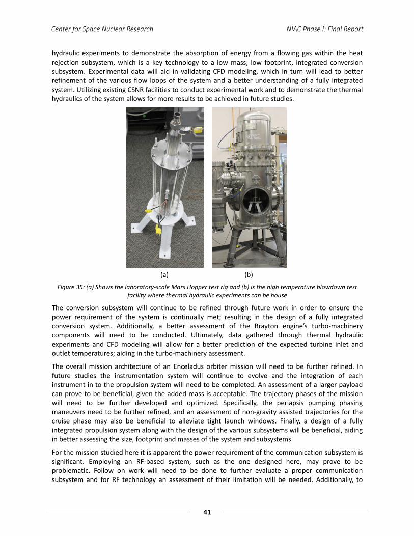
Center for Space Nuclear Research NIAC Phase I: Final Report
41
hydraulic experiments to demonstrate the absorption of energy from a flowing gas within the heat rejection subsystem, which is a key technology to a low mass, low footprint, integrated conversion subsystem. Experimental data will aid in validating CFD modeling, which in turn will lead to better refinement of the various flow loops of the system and a better understanding of a fully integrated system. Utilizing existing CSNR facilities to conduct experimental work and to demonstrate the thermal hydraulics of the system allows for more results to be achieved in future studies.
(a) (b)
Figure 35: (a) Shows the laboratory-scale Mars Hopper test rig and (b) is the high temperature blowdown test facility where thermal hydraulic experiments can be house
The conversion subsystem will continue to be refined through future work in order to ensure the power requirement of the system is continually met; resulting in the design of a fully integrated conversion system. Additionally, a better assessment of the Brayton engine’s turbo-machinery components will need to be conducted. Ultimately, data gathered through thermal hydraulic experiments and CFD modeling will allow for a better prediction of the expected turbine inlet and outlet temperatures; aiding in the turbo-machinery assessment.
The overall mission architecture of an Enceladus orbiter mission will need to be further refined. In future studies the instrumentation system will continue to evolve and the integration of each instrument in to the propulsion system will need to be completed. An assessment of a larger payload can prove to be beneficial, given the added mass is acceptable. The trajectory phases of the mission will need to be further developed and optimized. Specifically, the periapsis pumping phasing maneuvers need to be further refined, and an assessment of non-gravity assisted trajectories for the cruise phase may also be beneficial to alleviate tight launch windows. Finally, a design of a fully integrated propulsion system along with the design of the various subsystems will be beneficial, aiding in better assessing the size, footprint and masses of the system and subsystems.
For the mission studied here it is apparent the power requirement of the communication subsystem is significant. Employing an RF-based system, such as the one designed here, may prove to be problematic. Follow on work will need to be done to further evaluate a proper communication subsystem and for RF technology an assessment of their limitation will be needed. Additionally, to

Center for Space Nuclear Research NIAC Phase I: Final Report
42
ensure the communication subsystem is maintained on the curve for communication technology an assessment of alternative communication technologies must be performed, specifically a comparable laser-based system must be assessed.
As more work is performed in maturing this concept, its motivation will continue to target lower mission costs. This will be continued through using the micro – satellite platforms and continuing with the design constraint of an IMLEO of < 1,000 kg; taking advantage of smaller launch vehicles.
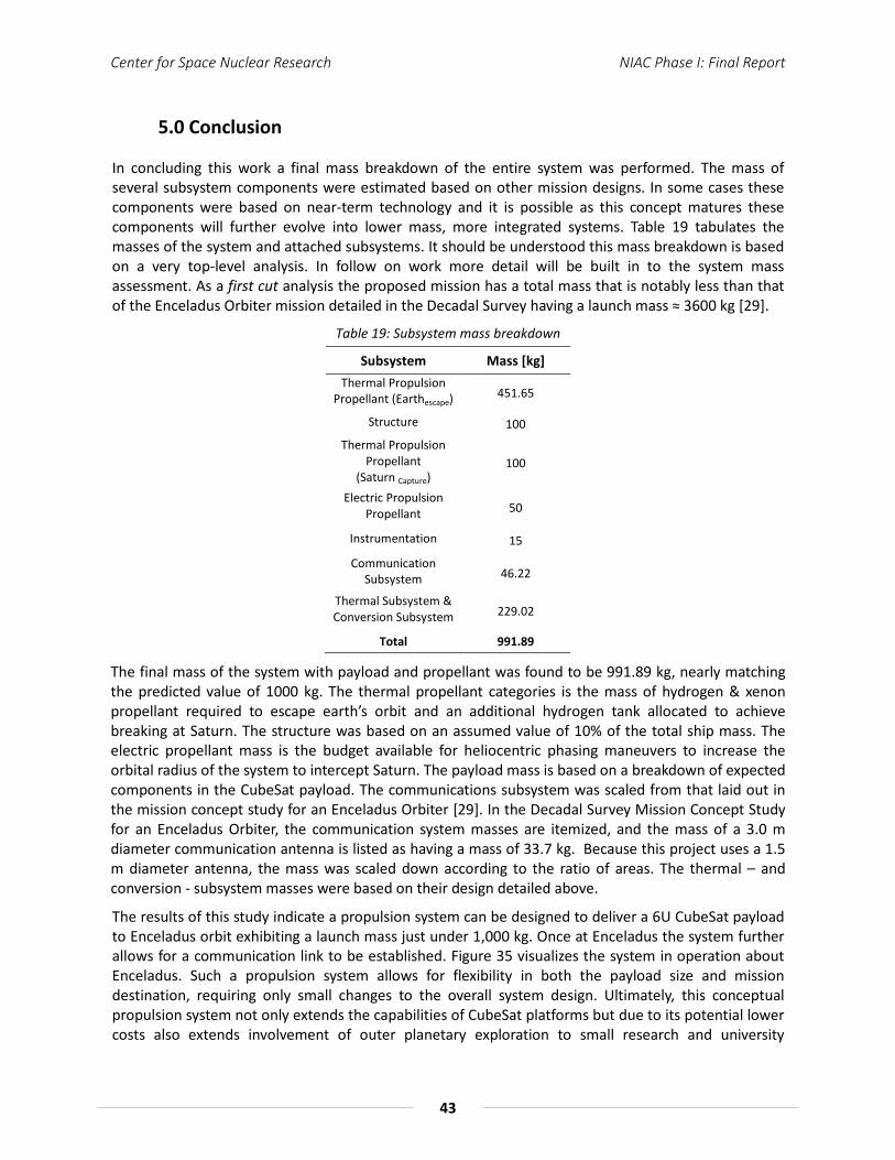
Center for Space Nuclear Research NIAC Phase I: Final Report
43
5.0 Conclusion
In concluding this work a final mass breakdown of the entire system was performed. The mass of several subsystem components were estimated based on other mission designs. In some cases these components were based on near-term technology and it is possible as this concept matures these components will further evolve into lower mass, more integrated systems. Table 19 tabulates the masses of the system and attached subsystems. It should be understood this mass breakdown is based on a very top-level analysis. In follow on work more detail will be built in to the system mass assessment. As a first cut analysis the proposed mission has a total mass that is notably less than that of the Enceladus Orbiter mission detailed in the Decadal Survey having a launch mass ≈ 3600 kg [29].
Table 19: Subsystem mass breakdown
Subsystem Mass [kg] Thermal Propulsion
Propellant (Earthescape) 451.65
Structure 100 Thermal Propulsion
Propellant (Saturn Capture)
100
Electric Propulsion Propellant 50
Instrumentation 15
Communication Subsystem 46.22
Thermal Subsystem & Conversion Subsystem 229.02
Total 991.89
The final mass of the system with payload and propellant was found to be 991.89 kg, nearly matching the predicted value of 1000 kg. The thermal propellant categories is the mass of hydrogen & xenon propellant required to escape earth’s orbit and an additional hydrogen tank allocated to achieve breaking at Saturn. The structure was based on an assumed value of 10% of the total ship mass. The electric propellant mass is the budget available for heliocentric phasing maneuvers to increase the orbital radius of the system to intercept Saturn. The payload mass is based on a breakdown of expected components in the CubeSat payload. The communications subsystem was scaled from that laid out in the mission concept study for an Enceladus Orbiter [29]. In the Decadal Survey Mission Concept Study for an Enceladus Orbiter, the communication system masses are itemized, and the mass of a 3.0 m diameter communication antenna is listed as having a mass of 33.7 kg. Because this project uses a 1.5 m diameter antenna, the mass was scaled down according to the ratio of areas. The thermal – and conversion - subsystem masses were based on their design detailed above.
The results of this study indicate a propulsion system can be designed to deliver a 6U CubeSat payload to Enceladus orbit exhibiting a launch mass just under 1,000 kg. Once at Enceladus the system further allows for a communication link to be established. Figure 35 visualizes the system in operation about Enceladus. Such a propulsion system allows for flexibility in both the payload size and mission destination, requiring only small changes to the overall system design. Ultimately, this conceptual propulsion system not only extends the capabilities of CubeSat platforms but due to its potential lower costs also extends involvement of outer planetary exploration to small research and university
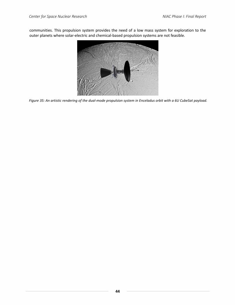
Center for Space Nuclear Research NIAC Phase I: Final Report
44
communities. This propulsion system provides the need of a low mass system for exploration to the outer planets where solar-electric and chemical-based propulsion systems are not feasible.
Figure 35: An artistic rendering of the dual-mode propulsion system in Enceladus orbit with a 6U CubeSat payload.
Center for Space Nuclear Research NIAC Phase I: Final Report
45
6.0 References
[1] Jerred, N. D., S. Cooley, R. C. O’Brien, and S. D. Howe. Proceedings of AIAA Space 2012 Conference. Pasadena. Print. Paper 5152.
[2] O’Brien, R. C., R. M. Ambrosi, N. P. Bannister, S. D. Howe, H. V. Atkinson. “Spark Plasma Sintering of Simulated Radioisotope Materials in Tungsten Cermets”. Journal of Nuclear Materials. 393 (2009) 108-113.
[3] Gaskell, David R. Introduction to the Thermodynamics of Materials. 4th ed. New York: Taylor & Francis, 2003. Print.
[4] Morgan, S., B. Manning, N. Addanki, M. Trubilla, S. Howe and J. King. “10kW Radioisotope Powered Pulsed Brayton Cycle for Space Applications.” Proceedings of Nuclear and Emerging Technologies for Space 2011. Albuquerque. Print. Paper 3303
[5] Howe, T., R. C. O'Brien, and C. M. Stoots. "Development of a Small-Scale Radioisotope Thermo-Photovoltaic Power Source." Proceedings of Nuclear and Emerging Technologies for Space 2012. Houston, Tx. Paper # 3059.
[6] Howe, S. D., R. C. O'Brien, R. M. Ambrosi, B. Gross, J. Katalenich, L. Sailer, M. McKay, J. C. Bridges, and N. P. Bannister. "The Mars Hopper: An Impulse-driven, Long-range, Long-lived Mobile Platform Utilizing in Situ Martian Resources." Journal of Aerospace Engineering Special Issue Paper (2010): 144-53. Print.
[7] Baum, E. M., H. D. Knox, T. R. Miller. Nuclide and Isotopes: Chart of Nuclides, 16th Ed., Lockheed Martin. (2002)
[8] O’Brien, R. C. “Radioisotope and Nuclear Technologies for Space Exploration.” PhD Thesis, University of Leicester, UK (2010)
[9] Kelley, K. K. “The Specific Heats at Low Temperatures Of Crystalline Boric Oxide, Boron Carbide And Silicon Carbide”. Journal of the American Chemical Society. 63 (1941) 1137-9.
[10] Kantor, K., P. B. Krasovitskaya, R. M. Kisil, O. M. Fiz. “Determining The Enthalpy And Specific Heat Of Beryllium In The Range 600-2200” Phys. Metals and Metallog. 10 (6) (1960) 42-4. Mcl-905/1, Ad-261792.
[11] Booker, J. Paine, R. M. Stonehouse, A. J. Wright. “Investigation Of Intermetallic Compounds For Very High Temperature Applications”. Air Development Division (1961) 1-133. Wadd Tr 60-889, Ad 265625.
[12] Pankratz, L. B. K. K. Kelley. Thermodynamic Data for Magnesium Oxide U S Bur Mines. Report. 1-5 (1963); Bm-Ri-6295.
[13] Kandyba, K., V. V. Kantor, P. B. Krasovitskaya, R. M. Fomichev, E. N. Dokl “Determination Of Enthalpy And Thermal Capacity Of Beryllium Oxide In The Temperature Range From 1200 – 2820” Aec-Tr-4310. (1960) 1-4.
[14] Hedge, J. C., J. W. Kopec, C. Kostenko, J. I. Lang. Thermal Properties Of Refractory Alloys. Aeronautical Systems Division. (1963) 1-128; ( Asd-Tdr-63-597, Ad 424375 )
[15] Metals Handbook, Vol.2 - Properties and Selection: Nonferrous Alloys and Special-Purpose Materials, ASM International 10th Ed. 1990.
[16] English, R., Technology for Brayton-Cycle Space Powerplants Using Solar and Nuclear Energy, NASA Technical Paper 2558, 1986
Center for Space Nuclear Research NIAC Phase I: Final Report
46
[17] MotoEnergy, ME1115, <http://www.motenergy.com/me1115motor.html>5/13/14
[18] R. B. Ross, Metallic Materials Specification Handbook, 4th ed., Chapman & Hall, London, 1992
[19] VinaTech, P-EDLC (Hybrid Capacitor), http://www.supercapacitorvina.com/product/p_edlc.html
[20] Spencer, J., Mission Concept Study: Planetary Science Decadal Survey JPL Rapid Mission Architecture (RMA) Enceladus Study Final Report. NASA (April 2010)
[21] Cassini-Huygens Mission. Cassini Orbiter. Epimethus Image. NASA/JPL/Space Science Institute. Cassini Imaging Team. <http://photojournal.jpl.nasa.gov/catalog/PIA09813>
[22] Cassini-Huygens Mission. Cassini Orbiter. Pandora Image. NASA/JPL/Space Science Institute. Cassini Imaging Team. < http://photojournal.jpl.nasa.gov/catalog/PIA07632>
[23] Cassini-Huygens Mission. Cassini Orbiter. Telesto Image. NASA/JPL/Space Science Institute. Cassini Imaging Team. < http://photojournal.jpl.nasa.gov/catalog/PIA07702>
[24] Cassini-Huygens Mission. Cassini Orbiter. Rhea Image. NASA/JPL/Space Science Institute. Cassini Imaging Team. < http://photojournal.jpl.nasa.gov/catalog/PIA07763>
[25] Cassini-Huygens Mission. Cassini Orbiter. Mimas Image. NASA/JPL/Space Science Institute. Cassini Imaging Team. < http://photojournal.jpl.nasa.gov/catalog/PIA12570>
[26] Cassini-Huygens Mission. Cassini Orbiter. Iapetus Image. NASA/JPL/Space Science Institute. Cassini Imaging Team. < http://photojournal.jpl.nasa.gov/catalog/PIA08384>
[27] Cassini-Huygens Mission. Cassini Orbiter. Hyperion Image. NASA/JPL/Space Science Institute. Cassini Imaging Team. < http://photojournal.jpl.nasa.gov/catalog/PIA07740>
[28] Cassini-Huygens Mission. Cassini Orbiter. Enceladus Image. NASA/JPL/Space Science Institute. Cassini Imaging Team. <http://photojournal.jpl.nasa.gov/jpeg/PIA06254.jpg>
[29] Spencer, J., Mission Concept Study: Planetary Science Decadal Survey Enceladus Orbiter. NASA (May 2010)
[30] Chandrayaan-1 Mission
[31] Esposito M., et. al., “A Highly Integrated Micropayload For Broadband Infrared Spectrometry (HIBRIS)”, Proc. of SPIE Vol. 7808, 780816 · © 2010 SPIE
[32] X-123CdTe from Amptek. <http://www.amptek.com/x123cdte.html>
[33] Owner’s manual for Argus 1000 IR Spectrometer, Thoth Technology, INC. Issue: 1.03, Document Number: OG728001. Available online from link – <http://www.thoth.ca/manuals/Argus%20Owner%27s%20Manual,%20Thoth%20Technology,%20Oct%2010,%20rel%201_03.pdf>
[34] CubeSatShop.com, NanoCam C1U. <http://www.cubesatshop.com/index.php?page=shop.product_details&product_id=63&flypage=flypage.tpl&pop=0&option=com_virtuemart&Itemid=65>
[35] GOMSPACE, Laser based instrument for the Exo Mars Mission (LAMBDA). <http://www.gomspace.com/index.php?p=profile-references>
[36] Hamid Hemmati (JPL), Editor. Deep Space Optical Communications [37] John Spencer and Curt Niebur. Mission Concept Study – Planetary Science Decadal Survey Jupiter
Europa Orbiter Component of EJSM.
Center for Space Nuclear Research NIAC Phase I: Final Report
47
[38] Elizabeth Turtle and Curt Niebur. Mission Concept Study – Planetary Science Decadal Survey Io Observer.
[39] Krishan Khurana and Curt Niebur. Mission Concept Study – Planetary Science Decadal Survey Ganymede Orbiter.
[40] William B. Hubbard. Mission Concept Study – Ice Giants Decadal Study Uranus Orbiter. [41] Rosaire, C. G., M. J. Heinemann, D. M. Krishna, S. S. Chittur, C. S. MacLachlan and S. D. Howe.
“Integrated Planetary Exploration Using Bimodal Radioisotope Power and Propulsion.” Proceedings of Nuclear and Emerging Technologies for Space 2013. Albuquerque. Print. Paper 6736.
[42] AeroJet Coporation. Electric Propulsion Data Sheet. Redmond, WA. (2003) [43] Putnam Z., et al., “Drag-Modulation Flight-Control System Options for Planetary Aerocapture”,
JOURNAL OF SPACECRAFT AND ROCKETS Vol. 51, No. 1, January–February 2014
[44] Orbital Sciences. Minotaur-C Launch System Fact Sheet. Dulles, VA. (2014)
[45] United Launch Alliance. Atlas V Launch Services User’s Guide. Centennial, CO. (2010)
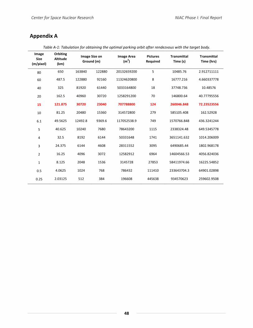
Center for Space Nuclear Research NIAC Phase I: Final Report
48
Appendix A
Table A-1: Tabulation for obtaining the optimal parking orbit after rendezvous with the target body. Image
Size (m/pixel)
Orbiting Altitude
(km)
Image Size on Ground (m)
Image Area (m2)
Pictures Required
Transmittal Time (s)
Transmittal Time (hrs)
80 650 163840 122880 20132659200 5 10485.76 2.912711111
60 487.5 122880 92160 11324620800 8 16777.216 4.660337778
40 325 81920 61440 5033164800 18 37748.736 10.48576
20 162.5 40960 30720 1258291200 70 146800.64 40.77795556
15 121.875 30720 23040 707788800 124 260046.848 72.23523556
10 81.25 20480 15360 314572800 279 585105.408 162.52928
6.1 49.5625 12492.8 9369.6 117052538.9 749 1570766.848 436.3241244
5 40.625 10240 7680 78643200 1115 2338324.48 649.5345778
4 32.5 8192 6144 50331648 1741 3651141.632 1014.206009
3 24.375 6144 4608 28311552 3095 6490685.44 1802.968178
2 16.25 4096 3072 12582912 6964 14604566.53 4056.824036
1 8.125 2048 1536 3145728 27853 58411974.66 16225.54852
0.5 4.0625 1024 768 786432 111410 233643704.3 64901.02898
0.25 2.03125 512 384 196608 445638 934570623 259602.9508

Center for Space Nuclear Research NIAC Phase I: Final Report
49
In the table below the orange boxes are the data, which is inserted in the communication model. All the losses in the orange boxes are data that is referenced from Cassini’s mission. The two purple boxes are the diameters inserted into the model. The blue boxes are the required performance values set by the user. All other boxes with no-fill of any color are equated using communication link budget equations. For the space loss distance, the maximum distance from Earth to Enceladus was considered in a 100 years span. So this communication model is designed for worse case situation.
Table A-2: Communication subsystem design model for down- & up-link transmission
Item Symbol Units
UPLINK DOWNLINK Spacecraft DSN
Value Value
Frequency f GHz 18.50 TRANSMITTER PARAMETERS
Transmitter Power Pt kW 25 Transmitter Power Pt Watts 25000.00 Transmitter Power Pt dBm 43.98
Transmit Antenna Diameter Dt m 1.50 34.00 Transmitter Antenna Beamwidth Θt deg 0.76
Spacecraft Transmitter Loss Lt dB -1.10 Spacecraft Circuit Loss L_Cir dB -0.20
Peak Transmit Antenna Gain Gpt dBi 46.72 Transmit Antenna Pointing Offset et deg 0.00 Transmit Antenna Pointing Loss Lpt dB 0.00
Degrees-off-boresight (DOFF) Loss DOFF dB 0.00 Obscuration Loss L_Obs dB 0.00
Equivalent Isotropic Radiated Power EIRP dBm 89.40 PATH PARAMETERS
Propagation Path Length S km 2337410240.00 Space Loss Ls dB -305.17
Atmospheric Attenuation La dB -0.35 RECEIVER PARAMETERS
Receive Antenna Diameter Dr m 1.50 34.00 Peak Receive Antenna Gain (net) Grp dBi 73.78
Receive Antenna Beamwidth Θr deg 0.03 Receive Antenna Pointing Error er deg 0.02 Receive Antenna Pointing Loss Lpr dB -3.11
Polarization Loss L_Pol dB -0.06 TOTAL POWER SUMMARY
Total Received Power TRP dBm -145.51 System Noise Temperature at Zenith SNT_Zenith K 17.55
System Noise Temperature due to Elevation SNT_Elevation K 1.34
System Noise Temperature due to SNT_Atm K 21.61
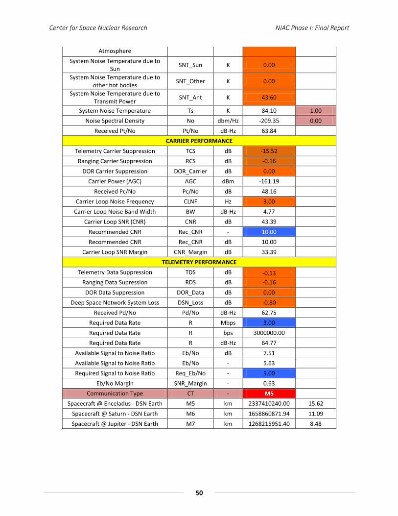
Center for Space Nuclear Research NIAC Phase I: Final Report
50
Atmosphere System Noise Temperature due to
Sun SNT_Sun K 0.00
System Noise Temperature due to other hot bodies SNT_Other K 0.00
System Noise Temperature due to Transmit Power SNT_Ant K 43.60
System Noise Temperature Ts K 84.10 1.00 Noise Spectral Density No dbm/Hz -209.35 0.00
Received Pt/No Pt/No dB-Hz 63.84 CARRIER PERFORMANCE
Telemetry Carrier Suppression TCS dB -15.52 Ranging Carrier Suppression RCS dB -0.16
DOR Carrier Suppression DOR_Carrier dB 0.00 Carrier Power (AGC) AGC dBm -161.19
Received Pc/No Pc/No dB 48.16 Carrier Loop Noise Frequency CLNF Hz 3.00
Carrier Loop Noise Band Width BW dB-Hz 4.77 Carrier Loop SNR (CNR) CNR dB 43.39
Recommended CNR Rec_CNR - 10.00 Recommended CNR Rec_CNR dB 10.00
Carrier Loop SNR Margin CNR_Margin dB 33.39 TELEMETRY PERFORMANCE
Telemetry Data Suppression TDS dB -0.13 Ranging Data Supression RDS dB -0.16 DOR Data Suppression DOR_Data dB 0.00
Deep Space Network System Loss DSN_Loss dB -0.80 Received Pd/No Pd/No dB-Hz 62.75
Required Data Rate R Mbps 3.00 Required Data Rate R bps 3000000.00 Required Data Rate R dB-Hz 64.77
Available Signal to Noise Ratio Eb/No dB 7.51 Available Signal to Noise Ratio Eb/No - 5.63 Required Signal to Noise Ratio Req_Eb/No - 5.00
Eb/No Margin SNR_Margin - 0.63 Communication Type CT - M5
Spacecraft @ Enceladus - DSN Earth M5 km 2337410240.00 15.62 Spacecraft @ Saturn - DSN Earth M6 km 1658860871.94 11.09 Spacecraft @ Jupiter - DSN Earth M7 km 1268215951.40 8.48