A study on the low cost production methods of mesophase ...
131
九州大学学術情報リポジトリ Kyushu University Institutional Repository A study on the low cost production methods of mesophase pitch based carbon fiber : Enhancement of the yield of mesophase pitch and shortening of the oxidation/stabilization time 島ノ江, 明生 https://doi.org/10.15017/4060196 出版情報:九州大学, 2019, 博士(工学), 課程博士 バージョン: 権利関係:
Transcript of A study on the low cost production methods of mesophase ...

九州大学学術情報リポジトリKyushu University Institutional Repository
A study on the low cost production methods ofmesophase pitch based carbon fiber :Enhancement of the yield of mesophase pitch andshortening of the oxidation/stabilization time
島ノ江, 明生
https://doi.org/10.15017/4060196
出版情報:九州大学, 2019, 博士(工学), 課程博士バージョン:権利関係:

A study on the low cost production methods of mesophase pitch
based carbon fiber
−Enhancement of the yield of mesophase pitch and
shortening of the oxidation-stabilization time−
Department of applied science for electronics and materials
interdisciplinary graduate school of engineering sciences
Kyushu university
Yoon・Miyawaki Lab
島ノ江 明生
Hiroki Shimanoe
February 2020

高性能ピッチ系炭素繊維の低価格化に関する研究
-前駆体ピッチの高収率化および不融化時間の短縮-
A study on the low cost production methods of mesophase pitch
based carbon fiber
−Enhancement of the yield of mesophase pitch and
shortening of the oxidation-stabilization time−
九州大学
総合理工学府
量子プロセス理工学専攻
2020年 2月
尹・宮脇研究室
島ノ江 明生
Hiroki Shimanoe
論文調査委員会
主査 九州大学 教授 尹 聖昊
副査 九州大学 教授 永長 久寛
副査 九州大学 准教授 宮脇 仁

Contents
Chapter 1. Introduction ........................................................................................ 1
1-1. Carbon fiber ................................................................................................................... 1
1-2. Classification of CF ....................................................................................................... 2
1-2-1. PANCFs .................................................................................................. 2
1-2-2. IPCFs ..................................................................................................... 3
1-2-3. MPCFs ................................................................................................... 3
1-3. Necessity of improvement of the yield of SMP ....................................................... 6
1-3-1. Problems on preparation of SMP ............................................................. 6
1-3-2. Approach for improving SMP yield .......................................................... 7
1-4. Problem of long-time oxidation-stabilization and its solution ........................... 9
1-5. The objective and contents of this study ............................................................... 10
Reference ............................................................................................................................... 13
Chapter 2. Improvement of spinnable mesophase pitch yield using a coal direct
extracted fraction ................................................................................................ 27
2-1. Introduction .................................................................................................................. 27
2-2. Experimental ................................................................................................................ 28
2-2-1. Preparation of SMP .............................................................................. 28
2-2-2. Melt-spinning, oxidation-stabilization, carbonization and graphitization 29
2-2-3. Characterization ................................................................................... 29
2-3. Results and discussion ................................................................................................ 31
2-3-1. Hydrogenation of HPC under various conditions ................................... 31
2-3-2. Formation of an anisotropic texture after hydrogenation and N 2 blowing
heat treatment ................................................................................................. 32
2-3-3. Mechanical properties of HPC derived MPCFs ...................................... 34
2-4. Conclusion ..................................................................................................................... 35
Reference ............................................................................................................................... 37

Chapter 3. Preparation of spinnable mesophase pitch by hybridization of raw
materials .............................................................................................................. 54
3-1. Introduction .................................................................................................................. 54
3-2. Experimental ................................................................................................................ 55
3-2-1. Pretreatment of raw materials ............................................................... 55
3-2-2. Preparation of SMP .............................................................................. 56
3-2-3. Characterization ................................................................................... 56
3-3. Results and discussion ................................................................................................ 56
3-3-1. Effect of raw material hybridization on the expression of anisotropic texture
....................................................................................................................... 56
3-3-2. Optimization of the hybridization ratio of EBOp and CTP ..................... 58
3-4. Conclusion ..................................................................................................................... 58
Reference ............................................................................................................................... 59
Chapter 4. Elucidation of Lyotropic liquid crystalline characteristics of
mesophase pitch and modifying its property and yield ....................................... 66
4-1. Introduction .................................................................................................................. 66
4-2. Experimental ................................................................................................................ 68
4-2-1. Materials and preparation ..................................................................... 68
4-2-2. Characterization ................................................................................... 68
4-3. Results and discussion ................................................................................................ 69
4-3-1. The correlation between the molecular stacking and anisotropic texture 69
4-3-2. Reduction of SP of MP using isotropic pitch .......................................... 70
4-4. Conclusion ..................................................................................................................... 71
Reference ............................................................................................................................... 73
Chapter 5. Shortening the total oxidation-stabilization time on preparation of
mesophase pitch-based carbon fiber ................................................................... 84
5-1. Introduction .................................................................................................................. 84
5-2. Experimental ................................................................................................................ 85

5-2-1. Material and melt-spinning ................................................................... 85
5-2-2. Oxidation-stabilization of spun fibers .................................................... 85
5-2-3. Carbonization and graphitization .......................................................... 86
5-2-4. Characterization ................................................................................... 86
5-3. Results and discussion ................................................................................................ 88
5-3-1. Stabilization of MP fibers under atmospheric and pressurised conditions
....................................................................................................................... 88
5-3-2. Oxidation-stabilization of MP fiber using laboratory stabilization
apparatus ........................................................................................................ 91
5-3-3. Yields of carbonization and graphitization of the stabilized fibers and the
mechanical performances of the carbonized and graphitized fibers .................. 93
5-4. Conclusion ..................................................................................................................... 96
Reference ............................................................................................................................... 97
Chapter 6. Conclusions ...................................................................................... 111
List of abbreviation ........................................................................................... 114
List of figures .................................................................................................... 116
List of tables ...................................................................................................... 120
Abstract in Japanese ......................................................................................... 122
Acknowledgements ............................................................................................ 125

1
Chapter 1. Introduction
1-1. Carbon fiber
Carbon fiber (CF) is a typical fibrous carbon which is composed of over 90 wt% of carbon
atoms. At the end of the 19th century, Thomas Edison and Joseph Swan invented the
incandescent bulb using carbonized cellulose (bamboo and cotton) as a filament because of
excellent electrical conductivity and thermo-resistivity properties [1, 2]. This is considered to
be the begin of CF. In 1959, Union Carbide Company started to produce the cellulose-based
CFs, however, they showed low Tensile Strength (TS) and Young’s Modulus (YM) due to their
low graphitizable property after carbonization, therefore their application was very limited as
an insulation material [3].
Polyacrylonitrile (PAN) and pitch-based CFs, which are now mainstream in the commercial
CF productions, were first invented in the 1960s. In 1961, Shindo in Japan and Johnson and
Morita in England have individually developed PAN-based CFs (PANCFs) with higher
mechanical properties than those of cellulose-based CFs [4−6]. In 1963 and 1966, Ohtani has
first developed both isotropic and mesophase pitch-based CFs (IPCFs & MPCFs) [7, 8].
Toray, Kureha, and Union Carbide companies stated to commercialize PANCFs, IPCFs and
MPCFs in 1970s, respectively [9−12]. Nowadays, many companies produce PANCFs, IPCFs
and MPCFs, and their main applications are fillers for composites in the areas of aerospace,
military and sports [11−13].
CF reinforced plastics (CFRPs) have better specific TS and YM than those of steel, aluminum
alloys and the other materials [14−17]. Therefore, CFRPs have been recognized as the main
route to apply the CFs as important structural materials for aerospace, military and sports. In
recent years, their main application has been expanded into the industries of energy-saving and
environmental protection areas such as structural materials for electric vehicle (EV), windmill
and construction [14−16]. The CF application to the car body is particularly expected due to its
direct effect on reducing fossil fuel consumption through the EV weight lightening. Jim deVries

2
at Ford Motor Company proposed the required CF mechanical properties regarding TS,
elongation ratio and YM of at least 1.7 GPa, 1.0% and 170 GPa, respectively, and he also
required to lower the CF price to less than 10−12 $/kg for car body use [17].
1-2. Classification of CF
General CFs are classified into three types, PANCFs, IPCFs and MPCFs (Fig. 1-1).
PAN and MPCFs are commercialized as high-performance CFs due to their high TS
and YM [11, 13]. IPCF is commercialized as a general performance CF due to its low
mechanical properties [12, 18−22].
1-2-1. PANCFs
PANCFs show higher TS (3.5–6.8 GPa), elongation ratio (0.6–2.4%), and YM (170–
650 GPa) [11]. Toray Company commercialized many grade PANCFs such as T-300
(TS: 3.5 GPa, YM: 230 GPa), T-800 (TS: 5.4 GPa, YM: 300 GPa), T-1000 (TS: 7.4
GPa, YM: 300 GPa) and so on [11]. The fibrous PAN, a precursor of PANCF, is mainly
prepared by the solution spinning of dissolution of PAN copolymer with solvents such
as dimethylformamide (DMF) and dimethylsulfoxide (DMSO) [23]. After then, the
PAN spun fiber is stabilized at 200–300oC in air or oxygen flows under tension to form
pyridine ladder molecules [24]. Pyridine ladder molecules prevent a ring closure -
dehydrogenation with exothermic reaction at carbonization and keep the fibrous form
[24]. After stabilization, PANCFs are obtained by carbonization at 1500–3000oC to
discharge nitrogen, oxygen and hydrogen elements as HCN, NH3, N2, CO2 and NO2,
and develop the carbon hexagonal networks and graphitization at over 3000oC to form
the graphitic structure for high mechanical properties [25]. Extension at carbonization
and graphitization needs to increase a molecular orientation in the fiber axis direction
and enhance TS of PANCFs [14]. PANCFs have high mechanical properties, but their

3
production cost is more than 20 $/kg mainly due to expensive PAN precursor fiber and
its low carbonization yield. Thus, its application is usually limited to the advanced
composite materials for the areas of aerospace and military.
1-2-2. IPCFs
Commercialized IPCFs exhibit a low TS (0.5–1.0 GPa) and YM (30–50 GPa), but
they are manufactured with relatively low production cost due to the cheap raw
material and high carbonization yield [12, 26]. Spinnable isotropic pitch (IP) is
prepared by heat treatment such as distillation using coal tar pitch (CTP), ethylene
bottom oil (EBO) and slurry oil (SO) as raw materials and is composed of polycyclic
aromatic hydrocarbons [26, 27]. IPCF is obtained by melt -spinning, oxidation-
stabilization at 200–350oC to form oxidative cross-linking among molecules of its spun
fibers and carbonization, and mainly applied to insulation, a brake friction pad and so
on due to its low thermal conductivity and high heat resistance (Fig. 1-2) [28]. IPCFs
exhibit low mechanical properties, but recently, Kim et al. successfully developed an
IP with a linear structure through a bromination-dehydrobromination reaction of EBO
and CTP and prepared IPCFs with TS of 2.0–2.4 GPa [18]. However, this IPCF still
suffers YM deficiency and the handling difficulties in the precursor pitch production.
On the other hand, low cost CFs derived from lignin, liquefied wood, biotar and
polyethylene were developed, but these CFs exhibit still low TS of 0.6–1.0 GPa and
very low YM of 20–30 GPa [19–22].
1-2-3. MPCFs
Brooks and Talor first found a carbonaceous liquid crystal pitch (mesophase pitch;
MP) at coal carbonization [29]. By the carbonization of an IP at over 400oC, the
deposition, dehydrogenation and polycondensation enable to form special planar
4
polycyclic aromatic hydrocarbons, and in this phase mesophase spheres start to
nucleate and grow to bulk mesophase through their agglomeration [30]. Mesophase
spheres express, grow and coalesce during liquid-phase carbonization and finally
change to 100% bulk MP. The size and morphology of anisotropic texture in MP are
very dependent on the mobility of mesophase spheres (the fluidity of pitch matrix)
during the growth and coalescence [30, 31]. If the viscosity is low, the arrangement of
planar aromatic hydrocarbons can be easier to grow and coalescence and they are able
to form the bulk flow domain type fusible MP. However, at the high viscosity, the
fluidity of pitch decreases and MP becomes infusible with no flow domain.
So far spinnable mesophase pitch (SMP) has been considered to have both Lyotropic
and Thermotropic liquid crystalline properties [32, 33]. Recently, our group has
considered SMP should be only Lyotropic liquid crystal but Thermotropic one. SMP is
usually composed of 2 kinds of molecular groups, that is, “solvent molecules” which
show isotropic texture and “mesogen molecules” which do anisotropic one but almost
infusible (Fig. 1-3) [32]. The size and morphology of the anisotropic texture of SMP
depend on the ratio of solvent molecules and mesogen molecules [32]. This confirms
the Lyotropic liquid crystalline property of SMP. If the concentration of mesogen
molecules exceeds a certain value (the criteria of bulk mesophase expression), SMP
can be obtained. Fig. 1-4 shows the change of anisotropic texture by the ratio of
benzene insoluble and soluble fractions of MP derived from naphthalene pitch [33].
Benzene insoluble is rich in mesogen molecules. The more the amount, the bigger the
size of the anisotropic texture. Such size and shape of anisotropic texture depend on
the temperature of heat treatment [33]. At high temperatures, the amount of anisotropic
texture decreases because of the relatively low concentration of mesogen molecules,
which must be due to the solvent-capability of solvent molecules [33]. This just looks
a Thermotropic liquid crystal property. However, the amount of anisotropic texture

5
may decrease due to an increase in the solubility of mesogen molecules. Therefore, I
can conclude that SMP must be a Lyotropic liquid crystal.
So far, SMP usually prepared from an IP by two processes of extraction of toluene
insoluble and heat treatment, or heat treatment and centrifugation [34, 35]. Mochida
et al. have proposed a very innovative preparation of SMP derived from naphthalene
as a raw material by catalytic heat treatment using HF/BF3 [36]. Furthermore,
Hochgeschurtz et al. have proposed the preparation of SMP from the petroleum pitch
by supercritical extraction [37]. Each of the above processes has advantages and
disadvantages. For example, the two process methods have the advantage of cheaper
equipment and operation costs, but the very low yield and very low spinnability of the
SMP are still a problem. Mochida’s and the supercritical extraction methods can
produce relatively high yields of SMP, but the costly equipment and high process
operation costs are problems to solve. In particular, SMP produced by the supercritical
extraction shows a high yield compared to raw materials of 25 wt% or more, but it is
known that the produced SMP has low spinnability.
Our group has recently proposed SMP can be prepared through the adequate
hydrogenation, heat treatment and thin layer evaporation (TLE) of the aromatic
hydrocarbons such as CTP and SO [38].
Here, hydrogenation usually lowers the carbon aromaticity of low materials of the
highly polycyclic aromatic hydrocarbons and side alkyl chains of aliphatic groups [39].
Heat treatment of over 400oC with N2 blowing can change such molecules to mesogen
molecules which can be stacked in (002) direction. The amounts of solvent and
mesogen molecules can be controlled by TLE for the removal of a little volatile matter.

6
1-3. Necessity of improvement of the yield of SMP
1-3-1. Problems on preparation of SMP
MPCF has high TS and YM and is expected as an effective filler for the applications
to the car body, windmill frame and structural beam for construction. However, such
applications of MPCFs have obviously limited because of the high price of MPCF,
which must be due to the low yield of SMP and high costs of hydrogenation of raw
materials and long-time energy consumable oxidation-stabilization of SMP fiber (Fig.
1-5) [40]. In general, severe hydrogenation of raw materials such as quinoline
insoluble free CTP (QI free CTP) and SO is necessary for achieving the excellent
spinnability of SMP. However, it results in the low preparation yield of SMP to less
than 10 wt% for the raw materials of CTP and SO [38, 40]. For example, the yield of
SMP derived from SO by hydrogenation using 1, 2, 3, 4-tetrahydroquinoline and heat
treatment is 5.0–10.0 wt% [38]. Over 30 wt% as the yield of SMP is required to
manufacture its CFs with a low production cost of 10–12 $/kg. The manufacturing
processes, such as supercritical toluene extraction of SO and HF/BF 3-catalyzed
preparation of naphthalene, have improved the production yield of SMP up to 20–45
wt% [36, 37]. However, as described previously, commercial production has been very
limited due to costly equipment and its operation costs and the relatively low
spinnability. For producing the low cost MPCFs, the first problem to be solved would
be to produce SMP with high yield using a cheaper process with low operation costs.
For this, a selection of cheap raw material and non-special high cost production process
are very important. Without special production processes such as supercritical
extraction or highly toxic catalytic process using HF/BF3, a cheap raw material which
exhibits high purity and has many aromatic hydrocarbons and usual production process
(no or low degree hydrogenation, N2 blowing heat treatment and TLE) needs to be used.

7
1-3-2. Approach for improving SMP yield
A coal direct extracted fraction (Hyper-coal: HPC) was tried to be an effective raw
material to obtain high SMP. HPC is prepared by solvent extraction of coal at 350–
400oC under high pressure using mixed-methylnaphthalene and it shows various
molecular properties dependent on the selected original coal and extraction conditions
such as temperature and pressure (Fig. 1-6) [41–44]. HPC has a low price of 0.1 $/kg,
a low impurity of less than 200 ppm and relatively high polycyclic aromatic
hydrocarbons which are composed of 2–8 membered rings [41, 42]. The application of
HPC has been still very limited to isotropic coke production, fuel for gasification, and
additive to cheap binder pitches. In recent years, Yang et al. reported that spinnable IP
was successfully developed by only mixed methyl naphthalene extraction and short -
time TLE of HPC [43, 44]. Among aromatic ring compositions of 2–8 or more
membered rings of HPC, relatively high polycyclic aromatic hydrocarbons are apt to
convert into non-melted coke components under the same heat treatment condition [41].
However, HPC, which is prepared without high temperature heat treatment of over
800oC like coal tar, contains some molecules with ethyl or longer alkyl side chain
groups that interfere with the molecular stacking, which must be removed for obtaining
mesogen molecules in the preparation of SMP [32]. For this reason, the hydrogenation
reaction needs for leveling the aromatic structures and reducing the alkyl contents
above ethyl [39].
Besides HPC, EBO is also a cheap source of polycyclic aromatic hydrocarbons, but
it has aromatic hydrocarbons which are composed of 1–3 membered rings with a long-
chain aliphatic group such as ethyl and propyl group [27]. EBO with low condensed
aromatic rings with long-chain aliphatic groups is also very difficult to be converted
into mesogen molecules because such molecular structures usually impede to produce
the planar shaped molecules that must be a precondition to require the stacked structure

8
[32]. If the molecular structures EBO molecules can be optimized to accept to mesogen
molecules by hydrogenation, the major components of EBO are decomposed into the
lower polycyclic aromatic hydrocarbons and only very low yield of SMP can remain
after N2 blowing heat treatment. On the other hand, CTP and SO are relatively high
polycyclic aromatic hydrocarbons [45, 46]. In particular, CTP is mainly composed of
highly polycyclic aromatic hydrocarbons which are composed of 3–4 membered rings
with only methyl group side chain [46]. Therefore, the molecular stacking probability
of CTP and SO is higher than EBO. Fig. 1-7 exhibits the average molecular structure
of EBO, SO and CTP [27, 45, 46].
From the above reasons, I came up with the hybridization of EBO with CTP or SO.
EBO is composed of aromatic hydrocarbons that have a role for solvent molecules and
CTP and SO have aromatic hydrocarbons as mesogen molecules for the effective
preparation of SMP with high yield. By adding CTP or SO into EBO, the mesophase
growth and coalescence of EBO derived pitch can be improved. In the past, the binder
pitch has been developed by the hybridization of CTP or SO with EBO [47, 48].
Through the hybridization of EBO with CTP or SO at an optimized balance, the novel
approach for obtaining the high SMP yield without severe hydrogenation would
become possible.
Commercialized SMP such as AR pitch has a 100% anisotropic texture and its
derived MPCF usually exhibits high mechanical properties [36]. However, the
spinnability of the AR pitch is still low, and its production cost is very high due to
costly equipment and operation costs for the special heat treatment. For improving the
spinnability and yield, I came up with that mesogen molecule extraction of AR-pitch
and mixing its extract with separately prepared IPs for lowering the softening point
(SP) of SMP. IP with a low SP is only composed of solvent molecules and can be
prepared with high yield. If the obtained pitch exhibits sill the same anisotropic

9
textures even by adding some addition of IP, the SP of SMP can decrease with
improving SMP yield.
1-4. Problem of long-time oxidation-stabilization and its solution
The manufacturing process of MPCFs consists of the multiple sub-processes of the
SMP preparation, spinning, oxidation-stabilization, carbonization, graphitization and
sizing. Though the reduction of SMP production cost is very important for
manufacturing low price MPCF, it also needs to improve the production process for
decreasing the production cost (Fig. 1-5). Especially, the sub-process of oxidation-
stabilization is the most time and energy-consuming and costly process in CF
manufacturing. Conventional oxidation-stabilization employs thermal oxidation using
enough amount of atmospheric air flow at a temperature range of 150–300°C and a
long duration of a few hours [49, 50]. Thus, it is one of the most important tasks to
shorten the total stabilization time to reduce the cost of manufacturing CFs. However,
shortening of the stabilization time, i.e. performing rapid oxidation at high
temperatures, usually lower the mechanical properties through the formation of a
heterogeneously oxidized state in the transverse section of pitch fibers [49]. Thus,
stabilization should proceed slowly to confer optimal and homogeneous distribution
of oxygen uptake on stabilized fibers across their transverse section, so a long
stabilization time at a relatively low temperature is required (Figs. 1-8 and 1-9) [50].
The cause of a long stabilization time is usually due to the slow diffusion of oxygen
molecules into the center part of pitch fiber. Yang et al. have estimated that the average
radii of free volumes on various SMP derived MP fibers were in the ranges of 0.24–
0.25 nm and 0.25–0.26 nm, respectively [51]. The average kinetic radii of oxygen and
nitrogen are 0.17 and 0.19 nm, respectively, indicating that it is very difficult for the

10
effective air diffusion to occur for rapid oxidation reactions in MP fibers
homogeneously in conventional atmospheric stabilization.
Cornec et al. and Fathollahi et al. reported that the oxidation-stabilization of MP
fibers under a moderate oxygen pressure could be effective in raising the amount of
oxygen uptake and increasing the stabilization depths significantly even at low
temperature [52, 53]. Therefore, the stabilization-oxidation of MP fibers under high
air pressure may enhance the slow diffusion rate of oxygen molecules and enable the
homogeneous oxidation for a short time.
1-5. The objective and contents of this study
The objective of this study is the development of low price MPCFs by improvement
of the SMP yield and shortening the oxidation-stabilization time.
In Chapter 1, the backgrounds, conception, approach and objective of this study
were introduced.
In Chapter 2, preparation with a high yield of SMP using a coal direct extracted
fraction and evaluation of its MPCF were performed. I adopted the very usual cheap
production process of the three-step processes of hydrogenation, N2 blowing heat
treatment and TLE using HPC as the raw material for SMP with high yield.
Hydrogenation was minimized to lower the molecular weight and high alkyl side chain
groups to improve fluidity by low polycondensation [39]. N2 blowing heat treatment
also lowered high alkyl side chains to enhance the molecular stacking. TLE effectively
removed volatile matters which were also the main reason for low spinnability. The
obtained MPCFs were analyzed for the mechanical property according to standard
methods.

11
In Chapter 3, I examined the effect on the growth and coalescence of anisotropic
texture and developed SMP by the hybridization of EBO with CTP or SO. SMP was
prepared by the hybridization of EBO with CTP or SO. Pressurized EBO, CTP and SO
were hybridized by bromination-dehydrobromination to form intermolecular
methylene bridge, to optimize the molecular structure, and to increase the average
molecular weight and the compatibility, followed by the N2 blowing heat treatment and
TLE [18, 54]. The hybridization effect on the development of anisotropic textures was
closely investigated.
In Chapter 4, the correlation between the anisotropic texture and the molecular
stacking at various weight ratios of AR-THFI and AR-THFS was examined. I tried to
decrease the SP of SMP using AR-THFI as mesogen fraction and CTP or SO derived
IP with a low SP as solvent one. It was closely examined the correlation between the
anisotropic texture and the molecular stacking at various weight ratios of mesogen
molecules and solvent molecules, and tried to adjust the SP of SMP using IP with a
low SP. By the tetrahydrofuran (THF) extraction of AR pitch which has 100 vol% of
anisotropic texture was fractionated into THF insoluble fraction of AR pitch (AR-
THFI) as mesogen molecules and THF soluble fraction (AR-THFS) as solvent
molecules. After the mixing heat treatment at various weight ratios of AR-THFI as
mesogen fraction and AR-THFS and IPs derived from CTP or SO with a SP of 140°C
as solvent one, MP were re-prepared by low temperature annealing. The stacking
height (Lc(002), interlayer spacing (d002), anisotropic texture and softening points of
the obtained pitches were examined for elucidating the Lyotropic liquid crystalline
property of AR-pitch and lowering and improving its SP and yield, respectively.
In Chapter 5, I tried oxidation-stabilization under high pressure of air to reduce the
total stabilization time without causing deterioration of the mechanical properties of
MPCFs. The oxidative stabilization of MP fibers under various pressures was carried

12
out to examine the pressure effect on the oxidation reaction and mechanical properties.
The oxygen uptake and distribution of AR pitch-based fiber stabilized under various
pressure of air and the mechanical properties of its carbonized and graphitized fibers
were examined.
In Chapter 6, the conclusions and future plans were summarized.

13
Reference
1. Edison TA. Electric lamp. US patent 223,898A;1880.
2. Edison TA. Manufacture of Filaments for Incandescent Electric Lamps. US patent
470,925;1892.
3. Bacon R. Filamentary graphite and method for producing the same. US patent
2,957,756;1959.
4. Shindo A, Fujii R, Sengoku S. Method for producing carbon products from an
acrylonitrile-based synthetic polymer (in Japanese). Japan patent S37-4405;1959.
5. Johnson W, Watt W. Structure of high modulus carbon fibres. Nature
1967;215:384−6.
6. Morita K, Miyachi H, Hiramatsu T. Stabilization of acrylic fibers by sulfur atoms
mechanism of stabilization. Carbon 1981; 19(1):11−8.
7. Ohtani S. On the carbon fiber from the molten pyrolysis products. Carbon
1965;3(1):31−4.
8. Ohtani S. Mechanism of the carbonization of MP carbon fiber at the low
temperature range. Carbon 1967;5:219−25.
9. Singer LS. The mesophase and high modulus carbon fibers from pitch. Carbon
1978;16(6):409−15.
10. Takahashi R, Hosoi T, Aiba T, Konno T. Method for manufacturing petroleum pitch
having high aromaticity. US patent 3,928,170;1975.
11. Toray Co Ltd. Technical data sheets. No. CFA-008, No. CFA-007, No. CFA-006,
No. CFA-003, and No. CFA-002.
12. Nippon Graphite Fiber Co Ltd. Technical data sheets. YSH, YS and XN series.
13. Kureha Chemical Co Ltd. Product catalogue for carbon fiber. KRECA.
14. Newcomb BA. Processing, structure, and properties of carbon fibers. Compos Pt
A Appl Sci Manuf 2016;91:262−82.

14
15. Liu Y, Kumar S. Recent progress in fabrication, structure, and properties of carbon
fibers. Polym Rev 2012;52:234−58.
16. Soutis C. Fibre reinforced composites in aircraft construction. Prog Aero Sci
2005;41(2):143−51.
17. Yang KS, Kim BH, Yoon SH. Pitch based carbon fibers for automotive body and
electrodes, Carbon Lett 2014;15:162−70.
18. Kim BJ, Eom Y, Kato O, Miyawaki J, Kim BC, Mochida I, et al. Preparation of
carbon fibers with excellent mechanical properties from isotropic pitches. Carbon
2014;77:747−55.
19. Baker DA, Rials TG. Recent advances in low-cost carbon fiber manufacture from
lignin. J Appl Polym Sci 2013;130(2):713−28.
20. Ma XJ, Zhao GJ. Structure and performance of fibers prepared from liquefied
wood in phenol. Fibers Polym 2008;9:405−9.
21. Postema AR. De root H, Pennings AJ. Amorphous carbon fibres from linear low
density polyethylene. J Mater Sci 1990;25:4216−22.
22. Prauchner MJ, Pasa VMD, Otani S, Otani C. Biopitch-based general purpose
carbon fibers: Processing and properties. Carbon 2005;43(3):591−7.
23. Huang X. Fabrication and properties of carbon fibers. Materials
2009;2(4):2369−403.
24. Dalton S, Heatley F, Budd PM. Thermal stabilization of polyacrylonitrile fibres.
Polymer 1999;40(20):5531−43.
25. Oberlin A. Carbonization and graphitization. Carbon 1984;22(6):521−41.
26. Alcañiz-Monge J, Cazorla-Amorós D, Linares-Solano A, Oya A, Sakamoto A,
Hosm K. Preparation of general purpose carbon fibers from coal tar pitches with
low softening point. Carbon 1997;35(8):1079−87.
27. Kim BJ, Kotegawa T, Eom Y, An J, Hong IP, Kato O, Nakabayashi K, Miyawaki J,

15
Yoon SH. Enhancing the tensile strength of isotropic pitch-based carbon fibers by
improving the stabilization and carbonization properties of precursor pitch. Carbon
2016;99:649−57.
28. Edie DD. The effect of processing on the structure and properties of carbon fibers.
Carbon 1998;36:345−62.
29. Brooks JD, Taylor GH. The formation of graphitizing carbons from the liquid
phase. Carbon 1965;3(2):187−93.
30. Mochida I, Korai Y, Ku CH, Watanabe F, Sakai Y. Chemistry of synthesis, structure,
preparation and application of aromatic-derived mesophase pitch. Carbon
2000;38(2):305−328.
31. Mochida I, Korai Y. The chemistry for the preparation of pitch based carbon fibers.
Polymer 1986;35:456−9.
32. Korai Y, Mochida I. Preparation and properties of carbonaceous ,mesophase-i
soluble mesophase produced from A240 and coal tar pitch. Carbon
1985;23(1):97−103.
33. Mochida I, Korai Y. Chemistry of mesophase pitch for its preparation and property
design. J Fuel Soc Jpn 1985;64:796−808.
34. Diefendorfu RD, Riggs D. Manufacturing method of optically anisotropic
deformable pitch, optically anisotropic pitch and pitch fiber. Japan patent S54-
160427;1979.
35. Izumi T, Naito T, Nakamura T. Optically anisotropic carbonaceous pitch for carbon
material, its nufacture, and manufacture of carbonaceous pitch fiber and carbon
fiber. Japan patent S57-088016;1982.
36. Mochida I, Shimizu K, Korai Y, Otsuka H, Sakai Y, Fujiyama S. Preparation of
mesophase pitch from aromatic hydrocarbons by the aid of HF/BF 3. Carbon
1990;28(2−3):311−9.

16
37. Hutchenson KW, Roebers JR, Thies MC. Fractionation of petroleum pitch by
supercritical fluid extraction. Carbon 1991;29(2):215−23.
38. Kato O, Uemura S, Korai Y, Mochida I. Preparation of mesophase pitch and high
performance carbon fiber from decant oil. J Jpn Petrol Inst 2004;47(2):100−6.
39. Otani S, Sanada Y. Foundation of carbonization engineering (in Japanese).
Tokyo:Ohmsha;1980.
40. Mochida I, Sakai Y, Fujiyama S, Komatsu M. Development of process for
manufacturing of mesophase pitch from aromatic hydrocarbons. Nippon Kagaku
Kaishi 1997;1:1−10.
41. Hamaguchi M, Okuyama N. Manufacturing process and applications of the hyper-
coal. Tanso 2013;257:149−56.
42. Okuyama N, Komatsu N, Shigehisa T, Kaneko T, Tsuruya S. Hyper-coal process to
produce the ash-free coal. Fuel Process Technol 2004;85(8−10):947−67.
43. Yang J, Nakabayashi K, Miyawaki J, Yoon SH. Preparation of pitch based carbon
fibers using hyper-coal as a raw material. Carbon 2016;106:28−36.
44. Yang J, Nakabayashi K, Miyawaki J, Yoon SH. Preparation of isotropic pitch-based
carbon fiber using hyper coal through co-carbonation with ethylene bottom oil. J
Ind Eng Chem 2016;34:397−404.
45. Zander M. On the composition of pitches. Fuel 1987;66(11):1536−39.
46. Mochida I, Oyama T, Korai Y. Formation scheme of needle coke from FCC-decant
oil. Carbon 1988;26(1):49−55.
47. Bai BC, Kim JG, Kim JH, Lee CW, Lee YS, Im JS. Blending effect of pyrolyzed
fuel oil and coal tar in pitch production for artificial graphite. Carbon Lett
2018;25:78−83.
48. Pérez M, Granda M, Santamaria R, Menéndez R. Preventing mesophase growth in
petroleum pitches by the addition of coal-tar pitch. Carbon 2003;41(9):1854−7.

17
49. Matsumoto T, Mochida I. Oxygen distribution in oxidatively stabilized mesophase
pitch fiber. Carbon 1993;31:143−7.
50. Yoon SH, Korai Y, Mochida I. Assessment and optimization of the stabilization
process of mesophase pitch fibers by thermal analyses. Carbon 1994;32:281−7.
51. Yang H, Yoon SH, Korai Y, Mochida I, Kato O. Microvoids present in anisotropic
mesophase pitch, their as-spun and annealed fibers. Chem Lett 2003;32:168−9.
52. Fathollahi B, Jones B, Chau PC, White JL. Injection and stabilization of mesophase
pitch in the fabrication of carbon–carbon composites. Part III: Mesophase
stabilization at low temperatures and elevated oxidation pressures. Carbon
2005;43:143−51.
53. Cornec LP, Rogers DK, Fain CC, Edie DD. A novel stabilization technique and its
influence upon carbonization yield. Extended Abstracts, CARBON’92, Deutsche
Keramische Gesellschaft, Essen, Germany 1992;710–2.
54. Ge C, Yang H, Miyawaki J, Mochida I, Yoon SH, Qiao W, Long D, Ling L.
Synthesis and characterization of high-softening-point methylene-bridged pitches
by visible light irradiation assisted free-radical bromination. Carbon
2015;95:780−8.

18
Fig. 1-1. The mechanical properties of CFs.

19
Fig. 1-2. Manufacturing process of pitch-based CFs.

20
Fig
. 1-3
. T
he i
ma
ge o
f m
ole
cu
lar w
eig
ht
dis
trib
uti
on
of
MP
’s c
om
po
nen
ts.

21
Fig. 1-4. The optical textures obtained by mixing benzene insoluble fraction (BI)
and soluble fraction of MP derived from naphthalene pitch at various
weight ratios and annealing.

22
Fig. 1-5. The production costs of each manufacturing process of MP-based carbon
fiber and target carbon fiber. based carbon fiber and target carbon fiber.

23
Fig
. 1-6
. M
an
ufa
ctu
rin
g p
roce
ss o
f H
yp
er-c
oal

24
Fig. 1-7. Average molecular structure of CTP, EBO and SO.

25
Fig. 1-8. DSC (solid line) and TGA (broken line) oxidation curves of a MP fiber (A:
Oxidation of aliphatic groups on the surface of pitch fibers, B&C: Oxidation of
aliphatic groups inside pitch fibers, D: Oxidation of aromatic carbons, E:
Combustion).

26
Fig. 1-9. TS and YM of CFs stabilized at various heating rates.

27
Chapter 2. Improvement of spinnable mesophase pitch yield using a
coal direct extracted fraction
2-1. Introduction
Carbon fiber reinforced plastic (CFRP) which has lighter weight and higher strength
than steel is considered as a suitable alternative as car-body material of automobiles
[1−3]. Jim deVries of the Ford Motor Company recommended that the tensile strength
(TS), elongation ratio and Young’s modulus (YM) of CF for car frames should be at
least 1.7 GPa, 1.0%, and 170 GPa, respectively, with a material price less than 10−12
$/kg [3]. Polyacrylonitrile-based carbon fibers (PANCFs) exhibit a higher TS,
elongation ratio, and YM than the required mechanical properties [4]. However, its
production cost is more than 20 $/kg due to expensive PAN precursor fiber and its low
carbonization yield. On the other hand, isotropic pitch-based CFs (IPCFs) have low
production costs owing to cheap raw material and a simple production process [5].
Nevertheless, IPCFs have not yet satisfied the required mechanical properties,
exhibiting TS of 0.5–1.0 GPa and YM of 30–50 GPa [6]. The mechanical properties of
IPCFs can be improved by designing novel molecular structures in the isotropic pitch
(IP) precursor using biomass, polymers, and coal and petroleum by-products [7−9].
Kim et al. successfully developed IP with a linear structure through a bromination-
dehydrobromination reaction of ethylene bottom oil and coal tar pi tch and prepared
IPCFs with TS of 2.0–2.4 GPa [9]. However, these fibers still suffer YM deficiency.
Mesophase pitch-based CFs (MPCFs) have high mechanical properties comparable
to IPCFs [10]. TS, elongation ratio and YM of MPCFs are 2.2–3.5 GPa, 0.2–1.7%, and
140–820 GPa, respectively [11], but the applications of MPCFs are very limited
because they have the high production cost due to low yield of spinnable mesophase
pitch (SMP). For example, the yield of SMP derived from decant oil by hydrogenation
using 1, 2, 3, 4-tetrahydroquinoline and heat treatment is 5.0–10.0 wt% [12]. We have
28
used direct coal extracted fraction (Hyper-coal: HPC) as an effective and inexpensive
raw material for the development of functional carbon products [13]. HPC is a unique
and cheap coal extracted material that can be obtained through direct solvent extraction
of coal using 1-methylnaphthalene as a solvent at 350–400°C under high pressure, and
it shows various molecular properties depending on the selected original coal and
extraction conditions of temperature and pressure [13−15]. It has very interesting
characteristics of low ash, high carbonization yield, and excellent thermoplastic
properties [14−15]. However, the application of HPC has been still very limited to
coke production, fuel for gasification, and additives for binder materials. Our group
has reported a method for the simple preparation of spinnable IP using only solvent
extraction and short-time thin layer evaporation (TLE) of HPC [13].
In this work, SMP with high pitch yield was developed through the usual three-step
process of hydrogenation, N2 blowing heat treatment, and short-time TLE using
selected HPC as the raw material. Mesophase pitch (MP) with good spinnability was
successfully fabricated at a yield of 50 wt% or more of raw HPC by optimizing each
process. In addition, I prepared MP-based carbonized and graphitized fibers through
melt spinning, stabilization, carbonization, and graphitization using the HPC -derived
MP, and then, the mechanical properties of the obtained MPCFs were evaluated.
2-2. Experimental
2-2-1. Preparation of SMP
HPC was supplied by Kobe Steel Co. Ltd. and used as a raw material without further
treatment. The used HPC was extracted using methyl naphthalene from the selected
GR bitumen coal under the specific extraction conditions [16].
HPC and 1, 2, 3, 4-tetrahydronaphthalene (tetralin) were mixed at 1:1 or 1:2 ratios
(w/w) and heat-treated at 400–450oC for 1–4 h under autogenous pressure using an

29
autoclave for hydrogenation. After removing tetralin from the hydrogenated HPC by
vacuum distillation, the samples were successively heat-treated at 415°C for 3–4 h
with N2 blowing. The heating rate was 5°C/min and the flow rate of N 2 was 600
mL/min for 50 g of the hydrogenated HPC. After heat treatment with N2 blowing heat
treatment, light molecular volatile matters were removed by TLE at 390°C for 10 min
under vacuum. The obtained pitches were abbreviated as HXNY and HXNY-TLE
(HXNY denotes HPC hydrogenated at 450°C for X h at a 1:2 ratio of HPC:te tralin
[w/w] followed by N2 blowing heat treatment for Y h). Fig. 2-1 shows schematic
images of the SMP-manufacturing processes for N2 blowing heat treatment and TLE.
2-2-2. Melt-spinning, oxidation-stabilization, carbonization and graphitization
The MP fibers were fabricated by a single-hole spinneret at 360–370°C with a
homemade mono-hole melt-spinning apparatus, which has a stainless-steel die hole
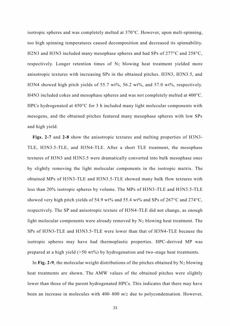
with diameter and length of 0.5 and 0.5 mm (L/D = 1), respectively [17]. Fig. 2-2
shows schematic images of the monofilament spinning apparatus and spinneret. The
MP fibers were stabilized at 270°C without a holding time under the air flow. The
heating rate was 0.5 °C/min and the flow rate of air was 200 mL/min. The stabilized
fibers were carbonized at 1000°C for 30 min with a heating rate of 20°C/min in a
vacuum, and the carbonized fibers were also further graphitized at 2800°C for 10 min
with a heating rate of 15 °C/min in an Ar atmosphere.
2-2-3. Characterization
The softening point (SP) and molten state of the prepared pitch were determined by
thermal mechanical analysis (TMA) (TMA/SS6300; EXSTAR6300 SII; Seiko Co. Ltd.,
Tokyo, Japan) from room temperature to 400°C at a heating rate of 5°C/min under N 2
flow.
30
Elemental analyses were conducted to determine the carbon, hydrogen and nitrogen,
contents, using an element analyzer (MT-5 CHN Corder; Yanako Co. Ltd., Tokyo,
Japan). The oxygen content was calculated by weight using the following equation:
Odiff. [wt%] = (100–C–H–N).
Molecular weight distribution and the average molecular weights (AMWs) were
estimated by time-of-flight mass spectrometry (TOF-MS) (JMS-S3000; JEOL Co. Ltd.,
Tokyo, Japan) after dissolving the pitch in tetrahydrofuran to a concentration of 1.0
wt%. The laser intensity was optimized to 55% with a delay time of 400 ns. Data more
than 100 test points were collected for each sample.
13C solid-state nuclear magnetic resonance spectroscopy (13C-NMR) (ECA400;
JEOL Co. Ltd.) was used to determine the molecular structure and aromaticity.
Chemical shifts were normalized to the methyl carbon resonance of solid
hexamethylbenzene at 17.4 ppm. Approximately 100 mg pulverized sample was added
to a zirconia standard sample rotor (diameter: 3.2 mm). The acquisition time was 0.05
s with a pulse of 90° and a width of 15 kHz. The method of 13C detection was DEPTH2
with magic-angle spinning (MAS) speed of 15 kHz.
Anisotropic textures of the obtained pitches were observed by polarization
microscope (POM) (BX51-P; Olympus Co. Ltd., Tokyo, Japan).
Images of the structure of the transverse sections and the surface morphology of the
graphitized fibers were obtained using a scanning electron microscope (JSM-6700F;
JEOL Co. Ltd.). Micrographs were acquired with an accelerating voltage of 5 kV.
The mechanical properties of the carbonized and graphitized fibers were measured
using a tensile tester (TENSILON/UTM-II-20; Orientec, Tokyo, Japan) in accordance
with the JIS R 7606:2000 method.

31
2-3. Results and discussion
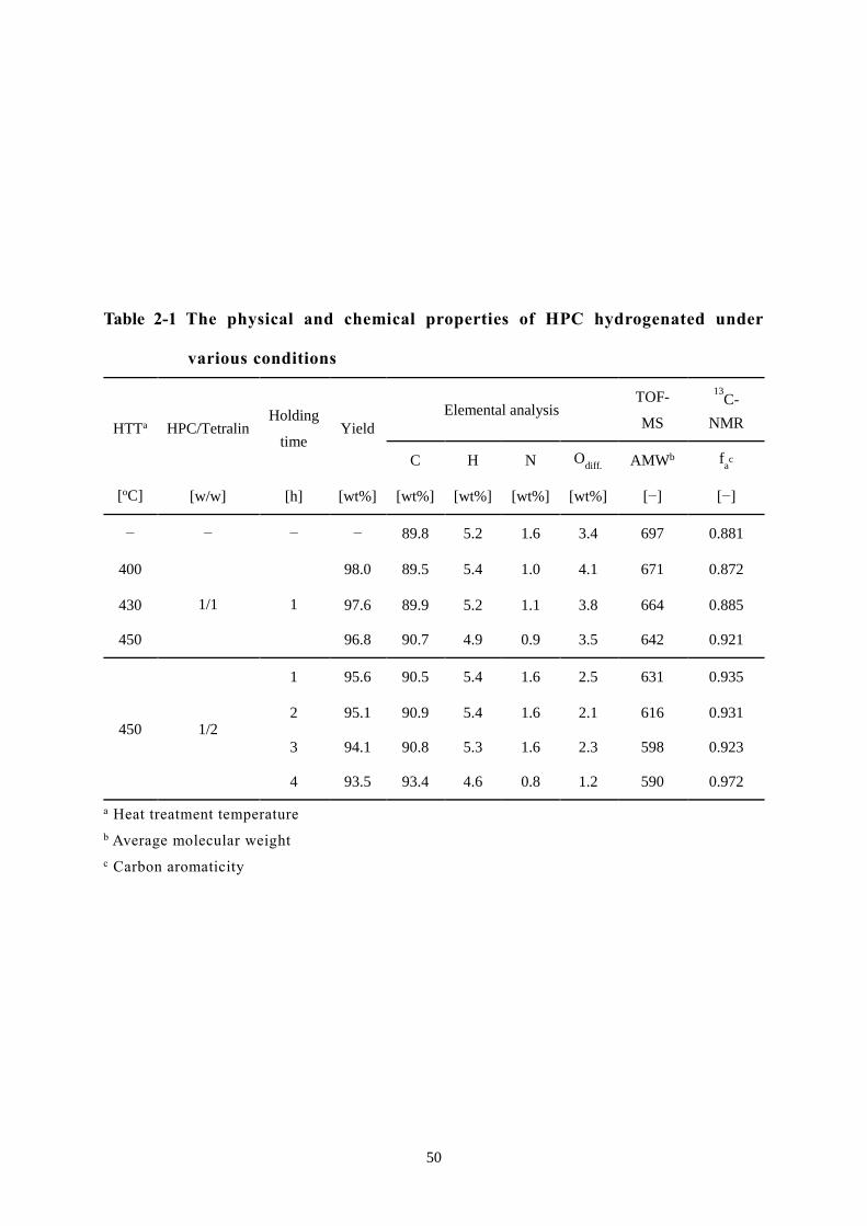
2-3-1. Hydrogenation of HPC under various conditions
Table 2-1 summarizes some of the physical and chemical properties of HPC
hydrogenated under various conditions. Fig. 2-3 shows the molecular weight
distributions of as-received and hydrogenated HPCs under various conditions. Fig. 2-
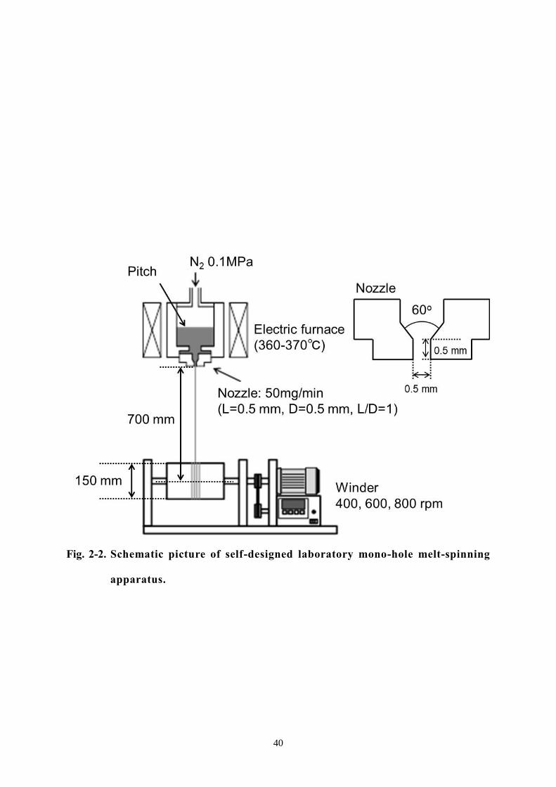
4 shows the 13C-NMR spectra of HPC hydrogenated under various conditions.
As shown in Figs. 2-3 and 2-4, it was clearly confirmed that as-received HPC
already has a high AMW of 697 m/z and carbon aromaticity of 0.88, which were higher
compared to typical IPs with high SP. This suggests that the as-received HPC, which
was directly extracted from coal at a high temperature and high pressure with
methylnaphthalene, already contains a large amount of high-molecular-weight and
fully developed high polynuclear aromatic molecular compositions. To effectively
manufacture a SMP using HPC as a raw material, it is necessary to induce the
naphthenic for the flexible molecular structures of the prepared MP and effectively
remove the alkyl components, except for the methyl group. In particular, it is essential
to introduce an enough height of 002 type layered molecular stacking for the proper
formation of flow domain texture of MP. Therefore, the hydrogenation of as -received
HPC was carried out to simultaneously give the mesophase texture and flexible
molecular structure for improved spinnability.
The TOF-MS and 13C-NMR spectra confirmed that the heavy molecular components
with m/z higher than 1000 were effectively converted into lighter molecular
components by hydrogenation, and the high temperature treatment of hydrogenation
easily caused a decomposition of heavy molecular components and changed methylene
chains to short-chain alkyls such as methyl groups [13]. Therefore, the top peak
molecular distribution and AMW of HPC hydrogenated at 450°C shifted to low
molecular-weights. The longer the retention time of hydrogenation, the greater the

32
increase in light molecular components. However, two top peaks appeared after
hydrogenation for 4 h. The results of elemental and 13C-NMR analyses suggested that
a coking reaction partially occurred because tetralin lost its hydrogen -donating
property [18]. The exothermic coking reaction may cause excessive decomposition and
increase specific molecules. The 13C-NMR spectra of HPCs hydrogenated at 400°C
and 430°C indicated an increase in the amount of methyl carbons (-CH3, 17–23 ppm),
methylene carbons inside aliphatic chains (-CH2-, 23–34 ppm), and bridge/hydro-
aromatic structures (Ar-CH2-Ar, 34–50 ppm) [19]. However, those at 450°C indicated
a decrease in the amount of -CH3, -CH2-, and Ar-CH2-Ar. The longer the retention time
of hydrogenation up to 3 h, the greater the increase in the amount of -CH3. On the
other hand, HPC hydrogenated at 450°C for 4 h exhibited a decrease in the amount of
aliphatic carbons due to the coking reaction. Hydrogenation at high temperatures for
long retention times caused the decomposition of methylene chains and heavy
molecular components. Based on these results, the hydrogenation conditions of the as -
received HPC were set to 450°C and 3 h.
2-3-2. Formation of an anisotropic texture after hydrogenation and N 2 blowing heat
treatment
Table 2-2 summarizes some of the physical and chemical properties of the pitches
obtained by hydrogenation, N2 blowing heat treatment, and TLE. Figs. 2-5 and 2-6
show the anisotropic textures and TMA profiles for determining the melting properties
of the pitches obtained after N2 blowing heat treatment, respectively.
N3, which was obtained by the N2 blowing heat treatment of as-received HPC for 3
h, exhibited an anisotropic flow texture and pores, but could not be melted owing to
coke production. The hydrogenation remarkably improved the melting behavior of
resultant pitches. For example, H1N3 had the flow type anisotropic texture with
33
isotropic spheres and was completely melted at 370°C. However, upon melt-spinning,
too high spinning temperatures caused decomposition and decreased its spinnability.
H2N3 and H3N3 included many mesophase spheres and had SPs of 277°C and 258°C,
respectively. Longer retention times of N2 blowing heat treatment yielded more
anisotropic textures with increasing SPs in the obtained pitches. H3N3, H3N3.5, and
H3N4 showed high pitch yields of 55.7 wt%, 56.2 wt%, and 57.0 wt%, respectively.
H4N3 included cokes and mesophase spheres and was not completely melted at 400°C.
HPCs hydrogenated at 450°C for 3 h included many light molecular components with
mesogens, and the obtained pitches featured many mesophase spheres with low SPs
and high yield.
Figs. 2-7 and 2-8 show the anisotropic textures and melting properties of H3N3-
TLE, H3N3.5-TLE, and H3N4-TLE. After a short TLE treatment, the mesophase
textures of H3N3 and H3N3.5 were dramatically converted into bulk mesophase ones
by slightly removing the light molecular components in the isotropic matrix. The
obtained MPs of H3N3-TLE and H3N3.5-TLE showed many bulk flow textures with
less than 20% isotropic spheres by volume. The MPs of H3N3-TLE and H3N3.5-TLE
showed very high pitch yields of 54.9 wt% and 55.4 wt% and SPs of 267°C and 274°C,
respectively. The SP and anisotropic texture of H3N4-TLE did not change, as enough
light molecular components were already removed by N2 blowing heat treatment. The
SPs of H3N3-TLE and H3N3.5-TLE were lower than that of H3N4-TLE because the
isotropic spheres may have had thermoplastic properties. HPC-derived MP was
prepared at a high yield (>50 wt%) by hydrogenation and two-stage heat treatments.
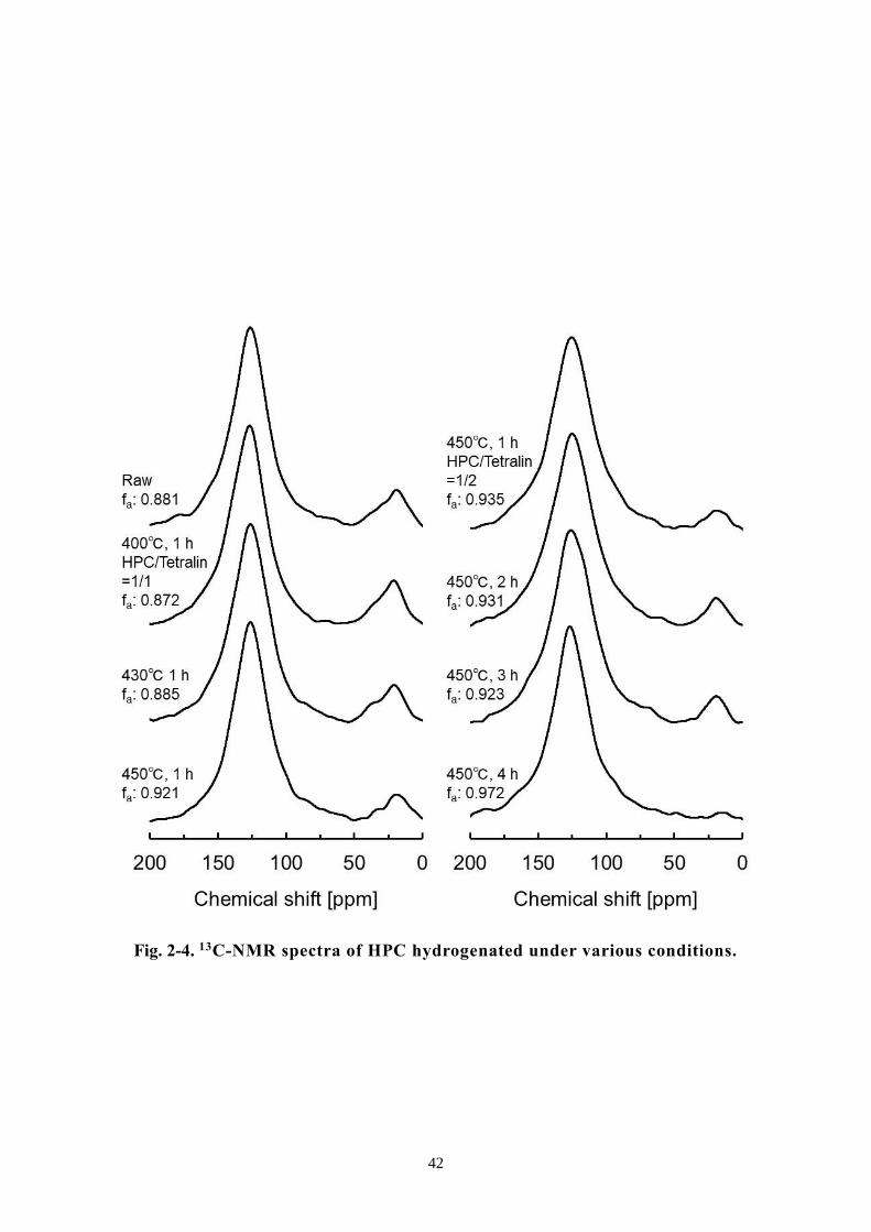
In Fig. 2-9, the molecular weight distributions of the pitches obtained by N2 blowing
heat treatments are shown. The AMW values of the obtained pitches were slightly
lower than those of the parent hydrogenated HPCs. This indicates that there may have
been an increase in molecules with 400–800 m/z due to polycondensation. However,

34
AMW of H4N3 was higher than that of HPC hydrogenated at 450°C for 4 h. The
exothermal reaction of coking caused excessive condensation and increased heavy
molecular components. AMWs of H3N3-TLE and H3N3.5-TLE increased by removing
the light molecular components by TLE. The obtained MPs included large quantities
of mesogens with the m/z values of 400–800.
Fig. 2-10 shows 13C-NMR spectra of the obtained pitches after the N2 blowing heat
treatment. The carbon aromaticity increased with increasing duration of the N 2 blowing
heat treatment through polycondensation, and light molecular components, including
non-mesogens, were removed. The more the amount of anisotropic structure increased,
the more the amounts of -CH2- and Ar-CH2-Ar decreased [19]. The 13C-NMR spectra
of H3N4 indicated a decrease in the amount of -CH2- and Ar-CH2-Ar. The obtained MP
included many aromatic carbons with methyl groups.
2-3-3. Mechanical properties of HPC derived MPCFs
Table 2-3 shows the evaluation results of the spinnability of H3N3-TLE and
H3N3.5-TLE and the diameters of spun fibers. The spun fibers of H3N3-TLE and
H3N3.5-TLE were successfully prepared by melt-spinning at winding speeds of 400
rpm and 600 rpm, respectively. However, a winding speed of 800 rpm was found to be
too fast to wind the spun fiber. The obtained pitches had few heavy molecular
components with m/z of 800–1000, which could impede a decrease in the viscosity of
the obtained pitches at 360–370°C. The diameters of spun fibers of H3N3-TLE and
H3N3.5-TLE at a winding speed of 600 rpm were 13.2 ± 0.5 μm and 13.4 ± 0.5 μm,
respectively.
Fig. 2-11 shows the surface and cross-section structures of the graphitized fibers.
The striation in the fiber axis direction was observed on the surface of the obtained
fibers, and the radial-random structure was observed on the cross-section of the

35
obtained fibers. Table 2-4 summarizes the mechanical properties of the carbonized and
graphitized fibers of H3N3-TLE and H3N3.5-TLE. TS, elongation, and YM of the
carbonized fibers of H3N3-TLE were 1.8 GPa, 1.4%, and 140 GPa, respectively, after
carbonization at 1000°C for 30 min, and the values for H3N3-TLE were 1.8 GPa, 1.4%,
and 130 GPa, respectively. TS of the carbonized fibers was high enough to meet the
objective CFs for the car frame, however, the elongation properties and YM were still
not satisfied. If the diameter of the carbonized fiber could be controlled to less than
10.0 μm through further improving the spinnability of the present MP, it must be fully
expected to manufacture the MPCF which can be applied to the car frame.
2-4. Conclusion
SMP with high preparation yield of 54.9 wt% was successfully prepared through the
three-step manufacturing process of hydrogenation, N2 blowing heat treatment, and
short TLE using HPC as an effective source of cheap raw material.
As-received HPC has many light and heavy molecular components including fully
developed polynuclear aromatic components with methyl groups and methylene chains.
The hydrogenation of HPC decreased the amount of methylene chains and heavy
molecular components with high polynuclear aromatic compounds. The N 2 blowing
heat treatment was necessary to reveal the mesophase texture but not to increase the
molecular weight and mesogen contents, including aromatic carbons. The short TLE
treatment was very effective to obtain the spinnable bulk texture of MP through the
slight removal of non-mesogen light molecular components. H3N3-TLE and H3N3.5-
TLE were very effectively converted into bulk MP with SPs increased by only less
than 10°C.
The obtained SMPs had a high yield (>50 wt%), which was likely due to the high -
molecular-weight and carbon aromaticity of the as-received HPC. HPC-derived

36
MPCFs showed high TS of 1.8 and 3.0 GPa and YM of 140 and 450 GPa after
carbonization at 1000°C for 30 min and graphitization at 2800°C for 10 min,
respectively.
We anticipate that the high-yield preparation of SMP from HPC as a raw material
can decrease the production cost of MPCFs, which could provide the opportunity to
apply CF to frames of popular cars.

37
Reference
1. Chand S. Carbon fibers for composites. J Mater Sci 2000;35(6):1303−13.
2. Huang X. Fabrication and properties of carbon fibers. Materials
2009;2(4):2369−403.
3. Yang KS, Kim BH, Yoon SH. Pitch based carbon fibers for automotive body and
electrodes, Carbon Lett 2014;15:162−70.
4. Toray Co Ltd. Technical data sheets. No. CFA-008, No. CFA-007, No. CFA-006,
No. CFA-003, and No. CFA-002.
5. Alcañiz-Monge J, Cazorla-Amorós D, Linares-Solano A, Oya A, Sakamoto A,
Hosm K. Preparation of general purpose carbon fibers from coal tar pitches with
low softening point. Carbon 1997;35(8):1079−87.
6. Kureha Chemical Co Ltd. Product catalogue for carbon fiber. KRECA.
7. Ma XJ, Zhao GJ. Structure and performance of fibers prepared from liquefied
wood in phenol. Fibers Polym 2008;9:405−9.
8. Postema AR. De root H, Pennings AJ. Amorphous carbon fibres from linear low
density polyethylene. J Mater Sci 1990;25:4216−22.
9. Kim BJ, Eom Y, Kato O, Miyawaki J, Kim BC, Mochida I, et al. Preparation of
carbon fibers with excellent mechanical properties from isotropic pitches. Carbon
2014;77:747−55.
10. Edie DD. The effect of processing on the structure and properties of carbon fibers.
Carbon 1998;36(4):345−62.
11. Mitsubishi Chemical Co Ltd. Product catalogue for carbon fibers.
12. Kato O, Uemura S, Korai Y, Mochida I. Preparation of mesophase pitch and high
performance carbon fiber from decant oil. J Jpn Petrol Inst 2004;47(2):100−6.
13. Yang J, Nakabayashi K, Miyawaki J, Yoon SH. Preparation of pi tch based carbon
fibers using hyper-coal as a raw material. Carbon 2016;106:28−36.

38
14. Hamaguchi M, Okuyama N. Manufacturing process and applications of the
hyper-coal. Tanso 2013;257:149−56.
15. Okuyama N, Komatsu N, Shigehisa T, Kaneko T, Tsuruya S. Hyper-coal process
to produce the ash-free coal. Fuel Process Technol 2004;85(8−10):947−67.
16. Yang J, Nakabayashi K, Miyawaki J, Yoon SH. Preparation of isotropic pitch-based
carbon fiber using hyper coal through co-carbonation with ethylene bottom oil. J
Ind Eng Chem 2016;34:397−404.
17. Liu J, Shimanoe H, Nakabayashi K, Miyawaki J, Ko S, Jeon YP, et al. Preparation
of isotropic pitch precursor for pitch-based carbon fiber through the co-
carbonization of ethylene bottom oil and polyvinyl chloride. J Ind Eng Chem
2018;67:276−83.
18. Otani S, Sanada Y. Foundation of carbonization engineering (in Japanese).
Tokyo: Ohmsha; 1980.
19. Diaz C, Blanco CG. NMR: A powerful tool in the characterization of coal tar
pitch. Energy Fuels 2003;17(4):907−13.

39
Fig. 2-1. Schematic picture of laboratory heat treatment apparatus: a) N 2 blowing
heat treatment and b) TLE.
40
Fig. 2-2. Schematic picture of self-designed laboratory mono-hole melt-spinning
apparatus.

41
.
Fig. 2-3. The molecular weight distributions of HPC hydrogenated under various
conditions.
42
Fig. 2-4. 13C-NMR spectra of HPC hydrogenated under various conditions.

43
Fig. 2-5. POM images of the obtained pitches after N2 blowing heat treatment.

44
Fig. 2-6. TMA profiles of the obtained pitches after N2 blowing heat treatment.

45
Fig. 2-7. POM images of the obtained pitches after N2 blowing heat treatment and
TLE.

46
Fig. 2-8. TMA profiles of the obtained pitches after N2 blowing heat treatment
and TLE.
47
Fig. 2-9. The molecular weight distributions of the obtained pitches after N 2
blowing heat treatment and TLE.

48
Fig. 2-10. 13C-NMR spectra of the obtained pitches after N2 blowing heat
treatment and TLE.

49
Fig. 2-11. SEM images of the surface structure and the cross-section of graphitized
fibers of H3N3-TLE and H3N3.5-TLE.
50
Table 2-1 The physical and chemical properties of HPC hydrogenated under
various conditions
HTTa HPC/Tetralin Holding
time Yield
Elemental analysis TOF-
MS
13C-
NMR
C H N Odiff.
AMWb fac
[oC] [w/w] [h] [wt%] [wt%] [wt%] [wt%] [wt%] [−] [−]
− − − − 89.8 5.2 1.6 3.4 697 0.881
400
1/1 1
98.0 89.5 5.4 1.0 4.1 671 0.872
430 97.6 89.9 5.2 1.1 3.8 664 0.885
450 96.8 90.7 4.9 0.9 3.5 642 0.921
450 1/2
1 95.6 90.5 5.4 1.6 2.5 631 0.935
2 95.1 90.9 5.4 1.6 2.1 616 0.931
3 94.1 90.8 5.3 1.6 2.3 598 0.923
4 93.5 93.4 4.6 0.8 1.2 590 0.972
a Heat treatment temperature
b Average molecular weight
c Carbon aromaticity

51
Table 2-2 The physical and chemical properties of the obtained pitches after N 2
blowing heat treatment and TLE
Yield TMA Elemental analysis TOF-MS
13C-NMR
SPa C H N Odiff.
AMWb fac
[wt%] [oC] [wt%] [wt%] [wt%] [wt%] [−] [−]
N3 88.3 − 89.9 4.8 0.8 4.5 − 0.951
H1N3 69.4 281 91.4 4.5 0.9 3.2 608 0.979
H2N3 62.0 277 91.4 4.6 0.9 3.1 578 0.953
H3N3 55.7 258 91.4 4.5 0.8 3.3 558 0.955
H3N3.5 56.2 264 91.6 4.4 0.8 3.2 555 0.958
H3N4 57.0 296 91.4 4.4 0.7 3.5 565 0.971
H4N3 54.6 286 93.8 3.8 0.4 2.0 585 0.997
H3N3-TLE 54.9 267 91.5 4.5 0.7 3.3 581 0.958
H3N3.5-TLE 55.4 274 91.7 4.4 1.0 2.9 577 0.960
H3N4-TLE 57.0 296 91.7 4.3 0.8 3.2 571 0.972
a Softening point b Average molecular weight c Carbon aromaticity

52
Table 2-3 The spinnability of H3N3-TLE and H3N3.5-TLE using self-designed
laboratory mono-hole melt-spinning apparatus and the average
diameter of spun fibers
Breakage number Diameter
400 rpm 600 rpm 800 rpm 400 rpm 600 rpm 800 rpm
[/3 min] [/3 min] [/3min] [µm] [µm] [µm]
H3N3-TLE 3 8 − 16.5±0.5 13.2±0.5 −
H3N3.5-TLE 4 9 − 16.5±0.5 13.4±0.5 −
53
Sta
bil
izat
ion
Car
bo
niz
atio
nG
raphit
izat
ion
Yie
ldY
ield
Dia
mete
rT
Sa
YM
bE
cY
ield
Dia
mete
rT
Sa
YM
bE
c
[%]
[%]
[µm
][G
Pa]
[GP
a][%
][%
][µ
m]
[GP
a][G
Pa]
[%]
H3
N3
-TL
E1
09
.08
4.7
10
.2±
0.5
1.8±
0.4
14
0±
20
1.4±
0.3
83
.89
.3±
0.4
3.0±
0.4
45
0±
60
0.7±
0.1
H3
N3
.5-T
LE
10
8.5
83
.91
0.5±
0.5
1.8±
0.5
13
0±
20
1.4±
0.2
83
.29
.8±
0.3
2.4±
0.4
37
0±
50
0.7±
0.1
a A
ver
age
tensi
le s
tren
gth
b A
ver
age
Young
’s m
odulu
s
c A
ver
age
elongat
ion
Ta
ble
2-4
Th
e yie
lds
an
d m
ech
an
ical
pro
per
ties
of
carb
on
ized
an
d g
rap
hit
ized
fib
ers
(Sp
un
fib
ers
at
win
din
g s
pee
ds
of
60
0 r
pm
)

54
Chapter 3. Preparation of spinnable mesophase pitch by hybridization
of raw materials
3-1. Introduction
Spinnable mesophase pitch (SMP) is used as an effective precursor for high -
performance mesophase pitch-based carbon fiber (MPCF) [1, 2]. As an effective MPCF
precursor, its high price has been considered as the main obstacle to broaden the MPCF
application areas. SMP is commercially produced from the petroleum and coal residues
(slurry oil (SO) and coal tar pitch (CTP)) through the complicated manufacturing
processes of purification, hydrogenation, mesofication in liquid phase carbonization
and other subside treatments such as volatile matter removal process with less than 10
wt% of final pitch yield to its raw material [3, 4].
Purification removes impurities such as inorganic materials and is costly.
Hydrogenation can lower the softening point (SP) of obtained SMP by introducing
naphthenic structure and reducing long-chain alkyl side groups, and coincidentally
decreasing excess carbon-aromaticity which is difficult to solve [5]. However, the
hydrogenation of raw materials is considered as a main reason for decreasing the pitch
yield and increasing the production cost. Therefore, the developmen t of SMP without
hydrogenation has been a long-time requirement for manufacturing the low price
MPCF. Furthermore, the manufacturing processes, such as supercritical toluene
extraction of SO and HF/BF3-catalyzed preparation of AR-mesophase pitch, have
improved the production yield of mesophase pitch (MP) up to over 20 wt% [6, 7].
However, commercial production has been very limited due to the costly equipment
and their operation costs, difficulty of operation, and relatively low spinnability. Thus,
the usual inexpensive production process (e.g. N2 blowing heat treatment and thin layer
evaporation (TLE)) needs to be used.

55
In this study, I tried to prepare SMP and examine the effects on the growth and
coalescence of anisotropic textures through the hybridization of ethylene bottom oil
(EBO) with CTP or SO. SMP is composed of solvent molecules that have hydrogen
donation property and mesogen molecules such as planar polycyclic aromatic
hydrocarbons with short-chain aliphatic side groups [8]. EBO is composed of aromatic
hydrocarbons which have a role for a solvent for mesogen molecules, and CTP and SO
have aromatic hydrocarbons as mesogen molecules [9−11]. Adding CTP or SO into
EBO, the mesophase expression, growth and coalescence of EBO derived pitch can be
improved. By hybridizing EBO, CTP and SO with optimized balance, SMP may be
prepared without excess hydrogenation. Hybridized EBO with CTP or SO was reacted
by bromination-dehydrobromination to form intermolecular methylene bridge,
optimize the molecular structure and increase the average molecular weight and the
compatibility, followed by the N2 blowing heat treatment and TLE [12, 13].
3-2. Experimental
3-2-1. Pretreatment of raw materials
Tetrahydrofuran soluble fractions of EBO, CTP and SO were used as raw materials
for SMP. EBO was pretreated by pressurized heat treatment at 370 oC for 3 h under
autogenous pressure to increase molecular weight (EBOp). EBOp was continuously
heat treated by bromination at 110oC for 2 h under Ar atmospheres using 0, 5 or 10
wt% of Br2 and dehydrobromination at 370oC for 3 h under Ar atmospheres. EBOp and
CTP or SO were mixed at the weight ratio of 3:7, 5:5 and 7:3, and the mixture was
treated by bromination-dehydrobromination under the same conditions (EBOp/CTP,
EBOp/SO and CTP/SO). Table 3-1 exhibits the average molecular weight and carbon
aromaticity of raw materials.

56
3-2-2. Preparation of SMP
SMPs were obtained by heat treatment at 425°C for 3−4 h with N2 blowing heat
treatment. The heating rate was 5°C/min and the flow rate of N 2 was 600 mL/min for
50 g of sample. After the heat treatment with N2 blowing, light molecular components
were removed by TLE at 390−410°C for 0−10 min under vacuum. Fig. 3-1 shows the
schematic images of the MP-manufacturing processes for N2 blowing heat treatment
and TLE.
3-2-3. Characterization
SPs of the prepared pitch were determined by thermal mechanical analysis (TMA)
(TMA/SS6300; EXSTAR6300 SII; Seiko Co. Ltd., Tokyo, Japan) from room
temperature to 400°C at a heating rate of 5°C/min under N2 flow.
Anisotropic textures of the obtained pitches were observed by polarization
microscopy (POM) (BX51-P; Olympus Co. Ltd., Tokyo, Japan).
3-3. Results and discussion
3-3-1. Effect of raw material hybridization on the expression of anisotropic texture
Table 3-2 shows the yield and SP of the obtained pitches after the N 2 blowing heat
treatment. Fig. 3-2 shows the anisotropic textures of the obtained pitches after the N 2
blowing heat treatment. The obtained pitch derived from EBOp brominated using 0, 5
and 10 wt% of Br2 exhibited high yields of 20.4, 21.7, 22.9 wt%, respectively. However,
these samples brominated using 0 and 5 wt% of Br2 had very high SPs of 320 and
324oC, respectively. Especially, at 10 wt% of B2, the obtained pitch was not able to be
melted and might change to a coke. The melt-spinning of the MPs derived from EBOp
only was failed because the decomposition of the prepared pitches occurred at spinning
temperature. In Fig. 3-2, MP derived from EBOp brominated at 5 wt% showed a mosaic

57
texture. If the fluidity of the pitch is good, the pitch shows the rapid growth of
mesophase spheres and good coalescence property during liquid phase carbonization
and the MP with flow domain anisotropic texture is possible to obtain [14]. Therefore,
much small mesophase spheres of the pitch derived from EBOp only might confirm
that the agglomeration and coalescence of the finely nucleated mesophase spheres were
difficult due to the high viscosity.
EBOp/CTP derived pitch showed a higher pitch yield of 27.0 wt% than EBOp/SO
and CTP/SO derived pitches (19.8 and 21.5 wt%, respectively). EBOp/CTP, EBOp/SO
and CTP/SO derived pitches exhibited SPs of 256, 285 and 236oC, respectively. As
shown in Table 3-1 and Fig. 3-2, the EBOp derived pitch had mosaic anisotropic
texture because EBOp is composed of aromatic hydrocarbons which include low
condensed aromatic rings and long side chains of aliphatic groups which impede the
molecular stacking. On the other hand, the EBOp/CTP derived pitch had mesophase
spheres (Anisotropy: 50 vol%) because CTP has polycyclic aromatic hydrocarbons
with short side chains of aliphatic groups such as methyl group and shows high
molecular stacking property [4, 9, 10]. Thus, the growth and coalescence of mesophase
spheres were improved by the addition of CTP into EBOp.
The EBOp/SO derived pitch showed the same volume of anisotropic texture with
EBOp/CTP derived pitch, but the size of mesophase spheres was smaller and the
agglomerated anisotropic textures appeared more distorted than EBOp/CTP derived
one. SO was composed of aromatic hydrocarbons with higher condensed aromatic rings
than EBOp, so the growth of mesophase spheres was a little improved by the addition
of SO [11]. However, the coalescence of mesophase spheres derived from EBOp/SO
was low because SO includes many long side-chained aliphatic groups.
CTP/SO derived pitch was more volume and size of anisotropic texture than other
pitches due to high molecular stacking properties. From the yield, SP and anisotropic

58
texture of the obtained pitches, the pitch including much mesophase spheres with low
SP can be obtained by the hybridization of EBOp and CTP.
3-3-2. Optimization of the hybridization ratio of EBOp and CTP
Table 3-2 and Fig. 3-3 show pitch yield, SP and anisotropic texture of the obtained
pitches after treatments of bromination-dehydrobromination and N2 blowing heat
treatment of EBOp and CTP with the hybridization ratios (w/w) of 3:7, 5:5 and 7:3.
With increasing the addition amount of CTP to EBOp, the growth and coalescence of
mesophase spheres were much improved, and SP decreased. After TLE of the
EBOp/CTP derived pitch brominated at a weight ratio of 3:7, the MP including the
anisotropic texture of 80 vol%, SP of 285oC and pitch yield of 23.1 wt% was obtained
(Fig. 3-4). MP derived from CTP without hydrogenation generally showed a high SP
of over 300oC due to highly condensed aromatic molecules [15]. The lower SP and
good fluidity of the obtained MP using the hybridized EBOp/CTP (3/7) might confirm
that the hybridization of EBO and CTP is an effective method to prepare the SMP
without severe hydrogenation of raw materials.
3-4. Conclusion
SMP with a high yield of 23.1 wt% was successfully prepared using hybridized
EBOp and CTP through bromination-dehydrobromination, N2 blowing heat treatment
and short-time TLE. From the results, it can be concluded that the raw material
hybridization method reflecting the molecular structural characteristics on mesophase
formation of each raw material is very effective for SMP manufacturing with low SP
and high yield without hydrogenation. The MP derived from EBOp/CTP with the
hybridization ratios of 3:7 (w/w) showed the anisotropic texture of 80 vol%, SP of
285oC and pitch yield of 23.1 wt% with relatively good fluidity.
59
Reference
1. Edie DD. The effect of processing on the structure and properties of carbon fibers.
Carbon 1998;36(4):345−62.
2. Mochida I, Korai Y, Ku CH, Watanabe F, Sakai Y. Chemistry of synthesis, structure,
preparation and application of aromatic-derived mesophase pitch. Carbon
2000;38(2):305−328.
3. Kato O, Uemura S, Korai Y, Mochida I. Preparation of mesophase pitch and high
performance carbon fiber from decant oil. J Jpn Petrol Inst 2004;47(2):100−6.
4. Mochida I, Sakai Y, Fujiyama S, Komatsu M. Development of process for
manufacturing of mesophase pitch from aromatic hydrocarbons. Nippon Kagaku
Kaishi 1997;1:1−10.
5. Otani S, Sanada Y. Foundation of carbonization engineering (in Japanese). Tokyo:
Ohmsha; 1980.
6. Zhuang MS, Gast K, Thies MC. Stagewise fractionation of petroleum pitches
with supercritical toluene. Ind. Eng. Chem. Res. 2002;41(1):78−84.
7. Mochida I, Shimizu K, Korai Y, Otsuka H, Sakai Y, Fujiyama S. Preparation of
mesophase pitch from aromatic hydrocarbons by the aid of HF/BF 3. Carbon
1990;28(2−3):311−9.
8. Korai Y, Mochida I. Preparation and properties of carbonaceous ,mesophase-i
soluble mesophase produced from A240 and coal tar pitch. Carbon
1985;23(1):97−103.
9. Kim BJ, Kotegawa T, Eom Y, An J, Hong IP, Kato O, Nakabayashi K, Miyawaki J,
Yoon SH. Enhancing the tensile strength of isotropic pitch-based carbon fibers by
improving the stabilization and carbonization properties of precursor pitch. Carbon
2016;99:649−57.
10. Zander M. On the composition of pitches. Fuel 1987;66(11):1536−39.
60
11. Mochida I, Oyama T, Korai Y. Formation scheme of needle coke from FCC-decant
oil. Carbon 1988;26(1):49−55.
12. Ge C, Yang H, Miyawaki J, Mochida I, Yoon SH, Qiao W, Long D, Ling L.
Synthesis and characterization of high-softening-point methylenebridged pitches
by visible light irradiation assisted free-radical bromination. Carbon
2015;95:780−8.
13. Kim BJ, Eom Y, Kato O, Miyawaki J, Kim BC, Mochida I, et al. Preparation of
carbon fibers with excellent mechanical properties from isotropic pitches. Carbon
2014;77:747−55.
14. Mochida I, Korai Y. The chemistry for the preparation of pitch based carbon fibers.
Polymer 1986;35:456−9.
15. Arai Y. Pitch-based carbon fiber. Tanso 2010;241:15−20.
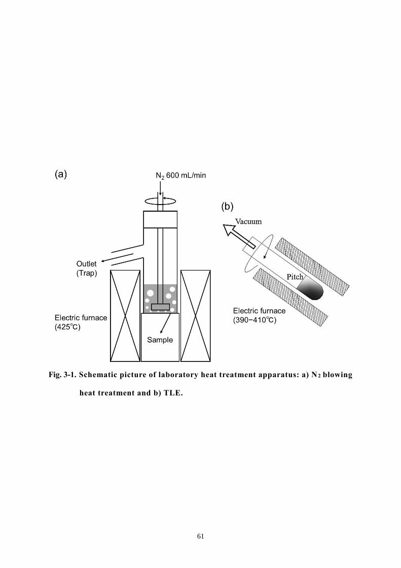
61
Fig. 3-1. Schematic picture of laboratory heat treatment apparatus: a) N 2 blowing
heat treatment and b) TLE.

62
Fig. 3-2. The anisotropic textures of the pitches derived from various raw
materials after N2 blowing heat treatment (Br2: 5 wt%).

63
Fig. 3-3. The anisotropic textures of the pitches derived from EBOp/CTP at
various weight ratios after N2 blowing heat treatment (Br2: 5 wt%).

64
Fig. 3-4. The anisotropic textures of the pitches derived from EBOp/CTP
at weight ratio of 3/7 after N2 blowing heat treatment and TLE
(Br2: 5 wt%).

65
Table 3-1 The aromaticity and average molecular weight of raw materials
13C-NMR TOF-MS
fa* AMW**
[−] [−]
EBO 0.748 202
EBOp 0.735 318
CTP 0.966 321
SO 0.701 264
* Carbon aromaticity
** Average molecular weight
Table 3-2 The yield and softening points of the pitches obtained by bromination-
dehydrobromination and N2 blowing heat treatment
Bromination-dehydrobromination N2 blowing heat treatment
Weight
ratio
Br2
amount Yield
Soaking
time Yield
Softening
point Anisotropy
[w/w] [wt%] [wt%] [h] [wt%] [℃] [vol%]
EBOp −
0 66.6
3
20.4 320 100
5 65.8 21.7 324 100
10 55.9 22.9 − −
EBOp/CTP
5/5 5
82.2
3
27.0 256 50
EBOp/SO 80.8 19.8 285 50
CTP/SO 82.2 21.5 236 60
EBOp/CTP
3/7
5
70.9
4
24.7 254 50
5/5 82.2 25.5 279 60
7/3 85.9 29.1 313 −

66
Chapter 4. Elucidation of Lyotropic liquid crystalline characteristics
of mesophase pitch and modifying its property and yield
4-1. Introduction
Spinnable mesophase pitch (SMP), which is one of the important precursors for high
performance carbon fiber, is usually produced through heat treatment of petroleum and
coal residues such as slurry oil (SO) and coal tar pitch (CTP) and other aromatic
hydrocarbons. SMP is formed by the liquid phase carbonization of such raw materials
at 350−500oC through volatilizing low molecular weight and stacking planar
condensed polycyclic aromatic hydrocarbons in a certain direction [1, 2].
SMP was known to have Lyotropic liquid crystal property [3, 4]. In general,
Lyotropic liquid crystal can show the specific liquid crystalline phase if its
concentration to a specific solvent is over the critical value. However, SMP has a
different molecular composition from typical Lyotropic liquid crystalline materials.
Lyotropic liquid crystal usually consists of mesogen molecules themselves, howeve r,
SMP is composed of both of mesogen molecules and solvent ones. Mesogen and
solvent molecules of SMP have a similar molecular structure but mesogen ones show
larger molecular weight [4]. The expression and shape of the anisotropic texture of
SMP should depend on the ratio of the solvent component and mesogen one in SMP
[4]. Soap, one of the typical Lyotropic liquid crystals, is composed of specific
molecules that have two different functions of hydrophilic and lyophilic in one
molecule. Such soap molecules form a very special molecular assembly of micelle
above the critical micelle concentration (CMC). SMP does not have different two
functions in one molecule, but it is composed of relatively highly planar molecules
which can be easily stacked in the direction of (002). Korai et al. have reported that
the molecular stacking height (Lc) of the mesophase pitch (MP) is larger than that of
the isotropic pitch in both solid and melt states [5], which means that SMP shows very

67
specific molecular assembly similar with soap molecules instead of the micelle. Kim
et al. have reported that a number of carbon hexagonal sheets in cluster effected on
microdomain structure and showed different graphitizability [6]. So far, however, the
correlation between the molecular stacking and optical anisotropy is not yet accurately
understood.
AR pitch, which was commercialized by Mitsubishi Gas Chemical Co. Ltd., has an
anisotropic texture of 100 vol% and its carbon fiber exhibits high mechanical
properties [7]. In this study, we tried to examine the Lyotropic property of SMP using
the mesogen molecules of AR pitch and also investigate the correlation between the
molecular stacking and optical anisotropy.
In order to extract mesogen fraction from SMP, we carried out solvent extraction of
AR pitch with tetrahydrofuran (THF), and assumed THF insoluble component (THFI)
of AR pitch as mesogen fraction and THF soluble component (THFS) as a solvent
fraction. Since the solubility of the mesogen fraction varies depending on the
molecular structure of the solvent. As solvent fractions, two isotropic pitches having
the same softening point (SP) with THFS of AR pitch were prepared from CTP and SO.
In order to examine the effect of the concentration of mesogen fraction on the
anisotropic texture and Lc of SMP, various ratios of mesogen fraction /isotropic pitch
were prepared and annealed at 350oC for 30 min. Finally, the correlation of anisotropic
contents and molecular stacking property was examined based on the measured values
of the anisotropic contents and Lc. SP of the re-prepared pitch was also measured for
investigation the SP decreasing effect with increasing the mixing fraction of various
solvent fractions.

68
4-2. Experimental
4-2-1. Materials and preparation
AR pitch was supplied from Mitsubishi Gas Chemical Co. Ltd. After the pulverizing,
AR pitch THF insoluble fraction (AR-THFI) and its THF soluble fraction (AR-THFS)
were obtained by solvent fractionation using THF at 50 oC. The yields of AR-THFI and
AR-THFS were 70 and 30 wt%, respectively. AR-THFI and AR-THFS were mixed at
weight ratios of 7:3, 6:4, 5:5, 4:6, 3:7, 2:8 and 1:9 (w/w) and heat -treated at 350oC for
30 min under N2 atmospheres. The heating rate was 5oC/min.
Isotropic pitches derived from CTP (CTP140) and SO (SO140) were used as solvent
molecules. SPs of CTP140 and SO140 were carefully controlled to 140 oC by TLE
because that of AR-THFS was 140oC. Mesogen fraction (AR-THFI) and solvent one
(CTP140 or SO140) were mixed at weight ratios of 7:3, 6:4, 5:5, 4:6 and 3:7 (w/w)
and annealed at 350oC for 30 min under the same conditions (AR-THFI/CTP140 and
AR-THFI/SO140).
4-2-2. Characterization
The stacking structure was examined by X-ray diffractometer (XRD, RINT-Ultima
Ⅲ , Rigaku Co., Tokyo, Japan) with CuKα radiation of 30 kV and 40 mA. Scanning
2θ range was 0–60o at the scan speed of 0.05o/min. The interlayer spacing (d002), the
stacking height (Lc(002)) and the number of stacking sheets were calculated by Brag
(Eq. 1), Scherrer (Eq. 2) equations and equation (Eq. 3), respectively [8, 9].
n= 2dsin (1)
Lc = K/cos (2)
Number of sheets = Lc/d+1 (3)

69
where, is the scattering angle, is the wavelength of the X-rays used, and is the
half-maximum line width in radian. The form factor K is 0.9 for Lc according to Jeffrey
et al. [10]. The values of d002 and Lc of samples were evaluated at 25–300oC.
SP of the prepared pitch were determined by thermal mechanical analysis (TMA)
(TMA/SS6300; EXSTAR6300 SII; Seiko Co. Ltd., Tokyo, Japan) from room
temperature to 400°C at a heating rate of 5°C/min under N2 flow.
Anisotropic textures of the obtained pitches were observed by polarization
microscope (POM) (BX51-P; Olympus Co. Ltd., Tokyo, Japan) using a heating stage
at 25, 100, 200, 250 and 300°C.
4-3. Results and discussion
4-3-1. The correlation between the molecular stacking and anisotropic texture
Fig. 4-1 shows POM images of the sample pitches obtained using mixtures of
various ratios of AR-THFI and AR-THFS. AR-THFS was fully isotropic, so it could
be considered that AR-THFS does not include mesogen molecules. At weight ratios of
7:3, 6:4 and 5:5 of AR-THFI and AR-THFS, the obtained pitches showed 100 vol%
anisotropic texture. At weight ratios of 4:6 of AR-THFI and AR-THFS, the obtained
pitch showed bulk anisotropic textures with isotropic spheres. As further increasing
the amount of AR-THFS, the isotropic matrix appeared with very small mesophase
spheres (3:7, 2:8 and 1:9). Fig. 4-2 and Table 4-1 shows the molecular stacking
parameters of AR-THFI/AR-THFS mixtures with various mixing ratios. At weight
ratios of 3:7, 2:8 and 1:9, the values of d002 and Lc(002) of obtained pitches, in which
isotropic matrix appeared, were larger and smaller than those of obtained pitches which
includes much anisotropic textures, respectively. Therefore, the number of stacked
sheets decreased in the conversion of a matrix from anisotropic to isotropic (Fig. 4-3).
From these results, it was found that the pitches which had the stacking sheets of over

70
10 indicated anisotropic textures but the pitches having the stacking sheets of about 7
showed the conversion of a matrix from anisotropic to isotropic.
Figs. 4-4 and 4-5 exhibit the stacking parameters and anisotropic textures of the
obtained pitches according to mixing ratio and XRD measuring temperature.
Increasing the measuring temperature, d002 increased and Lc decreased. Therefore, the
number of stacking sheets decreased with increasing the measuring temperature.
However, the number of stacking sheets of the obtained pitches which had anisotropic
textures of 100 vol% at high temperature was larger than those of the obtained pitches
showing much isotropic matrix at room temperature. Thus, it could be suggested that
SMP shows its Lyotropic liquid crystalline characteristics with the formation of the
specific molecular assembly of molecular stacking at both room and high temperature.
4-3-2. Reduction of SP of MP using isotropic pitch
Figs. 4-6 and 4-7 and Table 4-2 show textures and SP of AR-THFI/CTP140 and AR-
THFI/SO140. At the mixing ratios of 7:3 and 6:4, AR-THFI/CTP140 exhibited 100
vol% anisotropic textures. As further increasing the amount of CTP140, isotropic
spheres started to appear in the bulk anisotropic texture and finally the matrix texture
was converted from anisotropic to isotropic. At the weight ratios of 6:4 and 5:5 of AR -
THFI/CTP140, SPs were 235 and 223oC, respectively, which were lower than that of
the pristine AR pitch (240oC). AR-THFI/SO140 showed the structure separated
anisotropy and isotropy phases at all weight ratios. Thus, the difference of physical
properties such as the structure and molecular weight of solvent fractions might be
effect on the compatibility of anisotropy and isotropy phases.
Figs. 4-8 and 4-9 and Table 4-3 show the stacking parameters of AR-THFI/CTP140
at various weight ratios. The obtained pitches with bulk anisotropic texture showed
small d002 and large Lc values, giving rise to a large number of stacking sheets. After

71
converting the texture from anisotropic to isotropic, the values of d002 increased and
Lc and the number of stacking sheets greatly decreased. From a comparison between
Figs. 4-3 and 4-9, the number of stacking sheets of AR-THFI/CTP140 derived MP
appeared larger than that of AR pitch. A solvent fraction of CTP140 contributed to
increasing the molecular stacking because the molecular stacking property of CTP
derived pitch usually shows the higher stacking property than the pitches derived from
naphthalene and other petroleum residues [11, 12].
4-4. Conclusion
In this study, we examined Lyotropic characteristics of MP using AR-pitch as a
sample. From the results, we newly understood the followings.
① SMP is surely a Lyotropic liquid crystal.
② Because SMP is composed of planar molecules, if the concentration of the mesogen
fraction goes to be above the critical value, the different higher molecular stacking
structure forms as a special molecular assembly and the texture is converted to be
bulk anisotropic.
③ AR pitch, which represents 100 vol% of anisotropic texture, is originally composed
of 7:3 ratios of mesogen and solvent fractions, but the same 100 vol% anisotropic
texture was also observed even at the ratios of 6:4 and 5:5, and the molecular
stacking property was rather higher at the ratio of 6:4 than that of the original AR
pitch, which might indicate that the ratio of 6:4 is the optimal mixing balance of
mesogen and solvent fractions.
④ The alternative solvent fractions of the CTP and SO derived isotropic pitches,
which have the same SP with isotropic texture same with THFS of AR pitch, have
lower solvent properties than AR-THFS. Among them, the CTP derived isotropic
pitch has higher solvent ability than the SO derived isotropic one. When CTP

72
derived isotropic pitch was used as a solvent, it showed 100 vol% of anisotropic
texture up to 6:4, and the MP obtained at 6:4 had a lower SP than the pristine AR
pitch, and pitch yield might be improved by higher than 10 wt%. Therefore, using
this method, we can expect that the pitch yield and spinnability can be improved.
The future improvement and complementary points of this study are as follows;
① Accurate definition and specification of mesogen fraction in SMP.
② Better understanding of the differences of mesogen fractions from various
resources such as CTP and petroleum and the preparation of more effective
mesogen fraction.
③ Identifying the solution mechanism of mesogen fraction with solvent one and
finding out the decisive solution factor.
④ Preparation low price SMP using this characteristics.
73
Reference
1. Mochida I, Korai Y, Ku CH, Watanabe F, Sakai Y. Chemistry of synthesis, structure,
preparation and application of aromatic-derived mesophase pitch. Carbon
2000;38(2):305−328.
2. Mochida I, Korai Y. The chemistry for the preparation of pitch based carbon fibers. Polymer
1986;35:456−9.
3. Korai Y, Mochida I. Preparation and properties of carbonaceous ,mesophase-i soluble
mesophase produced from A240 and coal tar pitch. Carbon 1985;23(1):97−103.
4. Mochida I, Korai Y. Chemistry of mesophase pitch for its preparation and property design.
J Fuel Soc Jpn 1985;64:796−808.
5. Korai Y, Mochida I. Molecular assembly of mesophase and isotropic pitches at their fused
states. Carbon 1992;30(7):1019−24.
6. Kim DW, Kil HS, Kim J, Mochida I, Nakabayashi K, Rhee CK, Miyawaki J, Yoon SH.
Highly graphitized carbon from non-graphitizable raw material and its formation
mechanism based on domain theory. Carbon 2017;121:301−8.
7. Mochida I, Shimizu K, Korai Y, Otsuka H, Sakai Y, Fujiyama S. Preparation of mesophase
pitch from aromatic hydrocarbons by the aid of HF/BF3. Carbon 1990;28(2−3):311−9.
8. Endo M, Kim C, Karaki T, Kasai T, Matthews MJ, Brown SDM, Dresselhaus MS, Tamaki
T, Nishimura Y. Structural characterization of milled mesophase pitch-based carbon fibers.
Carbon 1998;36(11):1633−41.
9. Short MA, Walker Jr. PL. Measurement of interlayer spacings and crystal sizes in
turbostratic carbons. Carbon 1963;1(1):3−9.
10. Jeffery JW. Methods in X-ray crystallography. Academic Press 1971:83.
11. Korai Y, Mochida I. Preparation and properties of carbonaceous ,mesophase-i soluble
mesophase produced from A240 and coal tar pitch. Carbon 1985;23(1):97−103.
12. Zander M. On the composition of pitches. Fuel 1987;66(11):1536−39.

74
Fig. 4-1. The anisotropic textures of the pitches derived from AR-
THFI/AR-THFS at various weight ratios.

75
Fig. 4-2. The stacking parameters of the pitches derived from
AR-THFI/AR-THFS at various weight ratios.

76
Fig. 4-3. The number of stacking sheets of the pitches derived from AR-THFI/AR-
THFS at various weight ratios.

77
Fig. 4-4. The stacking parameters of the pitches derived from AR-THFI/AR-THFS
at various weight ratios and temperatures.

78
Fig
. 4-5
. T
he p
ola
riz
ati
on
mic
ro
sco
pe i
ma
ges
an
d n
um
ber o
f st
ack
ing
sh
eets
of
the p
itch
es
deriv
ed
fro
m A
R-T
HF
I/A
R-T
HF
S a
t v
ario
us
weig
ht
ra
tio
s a
nd
tem
pera
tures.

79
Fig. 4-6. The anisotropic textures of the pitches derived from AR-THFI/CTP140 at
various weight ratios.

80
Fig. 4-7. The anisotropic textures of the pitches derived from AR-THFI/SO140 at
various weight ratios.

81
Fig. 4-8. The stacking parameters of the pitches derived from AR-THFI/CTP140
at various weight ratios.

82
Fig. 4-9. The number of stacking sheets of the pitches derived from AR-
THFI/CTP140 at various weight ratios.

83
Table 4-1 The stacking parameters of the pitches derived from AR-THFI/AR-THFS
at various weight ratios
AR-
THFI AR pitch
Weight ratio of AR-THFI/AR-THFS [w/w] AR-
THFS 7/3 6/4 5/5 4/6 3/7 2/8 1/9
d002
[nm] 0.351 0.353 0.353 0.352 0.354 0.355 0.357 0.360 0.360 0.370
Lc [nm] 3.59 3.59 3.75 3.93 3.30 2.99 2.22 2.13 2.05 1.53
Table 4-2 The SPs of the pitches derived from AR-THFI/CTP140 and AR-
THFI/SO140 at various weight ratios
Weight
ratio [w/w] 7/3 6/4 5/5 4/6 3/7
AR-THFI/CTP140 SP [
oC]
255 235 223 230 234
AR-THFI/SO140 266 253 240 255 256
Table 4-3 The stacking parameters of the pitches derived from AR-THFI/CTP140
at various weight ratios
Weight
ratio [w/w] 7/3 6/4 5/5 4/6 3/7
AR-THFI/CTP140 d
002 [nm] 0.350 0.349 0.350 0.353 0.352
Lc [nm] 4.17 4.50 4.09 3.23 3.20

84
Chapter 5. Shortening the total oxidation-stabilization time on
preparation of mesophase pitch-based carbon fiber
5-1. Introduction
Stabilization process is the most time-consuming process in carbon fiber (CF)
manufacturing. Such a long time-consuming in stabilization is usually induced from
the slow oxidation of the precursor fiber at relatively low temperature because rapid
oxidation might be a reason for deteriorating the final mechanical properties of the
obtained CF. Due to this reason, it is one of the most important assignments to decrease
the consuming time in the stabilization process in CF manufacturing [1]. The cause of
a long stabilization time is the slow diffusion rate of oxygen molecules into the center
part of pitch fiber. Yang et al. have estimated that the average radii of free volumes on
various mesophase pitches (MPs) and their fibers were in the ranges of 0.24–0.25 nm
and 0.25–0.26 nm, respectively [2]. The average kinetic radii of oxygen and nitrogen
are 0.17 and 0.19 nm, respectively, which means that it is very difficult for the effective
air diffusion to occur for optimized oxidation reactions in MP fibers in conventional
atmospheric stabilization. The fiber stabilized at low temperature for long time has a
uniform distribution of the oxygen amount in the cross-section of pitch fiber and the
uniform distribution is one of the prior conditions to obtain the high tensile strength
(TS) in the CF after the carbonization [3, 4].
In this work, the effect of oxidation-stabilization under high pressure of air was
examined to reduce the total stabilization time without causing deterioration of the
mechanical performance of MP-based CFs (MPCFs). Cornec et al. and Fathollahi et
al. have reported that the oxidation-stabilization of MP fibers under a moderate oxygen
pressure is effective in raising the amounts of oxygen uptake and increasing the
stabilization depths significantly even at low temperature [5, 6]. Therefore, the
stabilization-oxidation of MPCF under high air pressure can be expected to enhance

85
the slow diffusion rate of oxygen molecules and enable the homogeneous oxidation for
a short time.
5-2. Experimental
5-2-1. Material and melt-spinning
AR mesophase pitch (ARMP) was supplied by Mitsubishi Gas Chemical Co., Japan,
and used as a model MP precursor in this study without further treatment. ARMP has
softening point (SP) at 240°C, carbon aromaticity of 0.84 and the content of the
mesophase texture of 100 vol.%. Table 5-1 summarizes general properties of ARMP
[7, 8].
ARMP was melt-spun into as-spun ARMP fiber (ARMP-F) using a single-hole
spinneret at 340°C with a laboratory-type mono-hole melt-spinning apparatus, which
has a stainless-steel die hole with diameter and length of 0.3 and 0.6 mm (L/D = 2),
respectively [9]. Fig. 5-1 shows a schematic diagram of the self-designed laboratory-
type spinning apparatus. The spinning conditions were carefully controlled to
diameters of spun MP fibers of just 10.5 ± 1.0 and 14.0 ± 1.0 µm, which were
designated as ARMP-F10 and ARMP-F14, respectively. ARMP-F14 was used to
examine the effect of pressure on the oxygen diffusivity and the oxidation reactions in
stabilization, and ARMP-F10 was used to prepare the carbonized and graphitized fibers
(ARMP-CF10 and ARMP-GF10) to evaluate the mechanical performance.
5-2-2. Oxidation-stabilization of spun fibers
Oxidation-stabilization of ARMP-Fs was carried out through thermal oxidation
under dry air flow of 0.1–1.0 MPa with a flow rate of 100 mL/min. Fig. 5-2 shows a
schematic diagram and an actual image of the custom-designed oxidation-stabilization
apparatus using atmospheric and pressurized air flows. Oxidation-stabilization of

86
ARMP-F14 was carried out at 270°C with a heating rate of 2.0°C/min for 20 min under
air flow pressures of 0.1, 0.5 and 1.0 MPa to evaluate the oxygen distribution across
the fiber cross-section. Oxidation-stabilization of ARMP-F10 was carried out at
various temperatures, heating rates, soaking times, and air flow pressures of 250–
270°C, 0.5–3.0°C/min, 0–60 min, and 0.1–1.0 MPa, respectively, to monitor the
oxygen uptake and prepare the optimally oxidation-stabilized fibers for evaluating the
mechanical performances of carbonized and graphitized fibers under each stabilization
condition. The stabilized fibers of ARMP-F10 and ARMP-F14 were designated ARMP-
SF10 and ARMP-SF14, respectively.
5-2-3. Carbonization and graphitization
After the stabilization of ARMP-Fs under various conditions, ARMP-SF14s were
successively heat-treated at 800°C for 5 min with a heating rate of 5.0°C/min in a N 2
atmosphere for carbonization, and further heat-treated at 2400°C for 10 min with a
heating rate of 15°C/min under an Ar atmosphere for graphitization. ARMP-SF10s
were heat-treated at 1000°C for 30 min with a heating rate of 20°C/min in a vacuum,
and some of the carbonized fibers were also further graphitized at 2800°C for 10 min
with a heating rate of 15oC/min in an Ar atmosphere to evaluate the mechanical
performance. The carbonized and graphitized fibers of ARMP-SF10 and ARMP-SF14
were named as ARMP-CF10 and ARMP-CF14, and ARMP-GF10 and ARMP-GF14,
respectively.
5-2-4. Characterization
Spun MP fibers were subjected to thermos-gravimetric analysis (TGA) to track the
amount of oxygen uptake under atmospheric and air flow pressure conditions using a
magnetic suspension balance (MicrotracBEL MSB-TG-1300; MicrotracBEL Co. Ltd.,

87
Osaka, Japan). Fig. 5-3 shows a schematic of MSB-TG-1300. TGA was carried out
under various heating rates and air flow pressures of 1.0–4.0°C/min and 0.1–1.0 MPa,
respectively. An exclusive alumina pan (diameter: 10 mm, height: 10 mm, weight: 6.11
g) was used under the controlled flows of air/oxygen with a flow rate of 100 mL/min.
After TGA, the activation energy of the oxidation-stabilization of ARMP-F14s was
calculated by Kissinger’s method using Eq. (5-1) [10]:
ln (q/Tmax2) = −Ea/(RTmax) (5-1)
where Tmax, q, and Ea denote peak temperature, heating rate, and activation energy,
respectively.
To evaluate the distribution of the amounts of oxygen uptake in the transverse
sections of stabilized fibers, ARMP-SF14s were analyzed using a scanning electron
microscope equipped with an electron probe micro-analyzer (JSM-6340F; JEOL,
Tokyo, Japan) [11]. Images of the structure of the transverse sections of the graphitized
fibers were obtained using a scanning electron microscope (JSM-6700F; JEOL). The
surface morphology and mean diameter of the resulting CFs were also measured.
Elemental analysis was used to determine the total amount of oxygen uptake of the
stabilized fibers for evaluating the mechanical performance of the obtained carbonized
and graphitized fibers. The mechanical properties of the carbonized and graphitized
fibers were measured using a universal tensile tester (TENSILON/UTM-II-20;
ORIENTEC, Tokyo, Japan), in accordance with the JIS R 7606:2000 method (A method
of single filament test) [12]. 25 filaments were tested for obtaining the averaged
mechanical properties. The averaged diameters of carbonized and graphitized fibers
were checked using a scanning electron microscope (SEM, JSM6700, JEOL, Japan) at
5 kV of acceleration voltage.

88
5-3. Results and discussion
5-3-1. Stabilization of MP fibers under atmospheric and pressurised conditions
Fig. 5-4 shows the TGA profiles of oxygen uptakes of ARMP-F14 and ARMP-F10
in oxidation stabilization with a heating rate of 2.0oC/min under atmospheric and
pressurized air flow conditions. ARMP-F10 and ARMP-F14 had very similar profiles
of oxygen uptake, which means that they experienced almost the same oxidation
reactions under the same applied pressure. Fig. 5-5 shows TGA profiles of the oxygen
uptakes of ARMP-F14 under the various heating rates and air flow pressures. The
results clearly revealed two interesting distinctions in the temperatures of the starting
and the maximum oxidations, and the amounts of oxygen uptake. First, t he oxidation
reaction for oxygen uptake occurred earlier in the stabilized fibers under air flow
pressures of 0.5 and 1.0 MPa than for the stabilized one under atmospheric pressure.
The start of oxygen uptake of ARMP-F14 mainly occurred at over 150°C under
atmospheric pressure regardless of the heating rate, whereas the pressurized
stabilization under 0.5 and 1.0 MPa allowed this to occur at around 125°C. During the
manufacture of MPCFs, the reactions that typically occur during the stabilization
process are oxidation, dehydration, condensation, oxidation crosslinking, elimination
of volatile matter and oxidative decomposition [13]. Such complexity in oxidation -
stabilization reactions makes it difficult to obtain a comprehensive understanding of
the stabilization of MP materials. However, Yoon et al. have successfully optimized
the stabilization process by performing a simple monitoring of oxygen uptake using
TGA with several heating rates [1]. For TGA, it allowed only two reactions of the
oxidation and oxidative decomposition of alkyl and aromatic molecules as main
reactions and proved that the oxidative decomposition of alkyl groups always occurred
before that of condensed aromatic ones. Based on this analysis, they explained that
oxygen uptake occurred at a lower temperature and higher rate with a decrease of the

89
heating rate in oxidation stabilization. They also proved that a higher heating rate,
which inevitably required a higher temperature to complete the optimal stabilization,
easily incurred excess oxidation in the outer section of MP fibers, and such excess
oxidation could trigger decomposition of the alkyl groups of pitch molecules with the
dissipation of decomposed gases such as CO and CO2 before the main decomposition
of aromatic molecules of MP fibers. In these results, the temperature at which the
maximum oxygen uptake in oxidation-stabilization occurred was shifted to a lower
position with increasing air pressure. This proved that the main oxygen uptake could
start at a lower temperature under pressurized air flow conditions than under
atmospheric conditions, and the application of pressure in oxidation stabilization is
expected to have a similar effect to decrease the heating rate. The observed earlier start
of oxidation and higher amounts of oxygen uptake were well matched with the previous
reports [5, 6].
Table 5-2 summarizes the activation energy, Ea, of the oxidation reactions in various
stabilized conditions from the calculation based on Eq. (5-1) using the Arrhenius plots
shown in Fig. 5-6. The activation energies at 0.5 MPa and 1.0 MPa were 230 kJ/mol
and 271 kJ/mol, respectively, which was less than almost half the value of 535 kJ/mol
at atmospheric pressure.
Regarding the maximum amount of oxygen uptake in the oxidation stabilization with
applied pressure, different effects of decreasing the heating rate were observed.
Specifically, the stabilized fiber of ARMP-SF14 at 0.5 MPa had a higher amount of
oxygen uptake at its maximum point of oxygen uptake than the stabilized fiber under
atmospheric conditions. However, the maximum amount of oxygen uptake at 1.0 MPa
was slightly lower compared with those under atmospheric pressure conditions. As is
clearly shown in Figs. 5-4 and 5-5, the oxidation rate under the pressure conditions of
1.0 MPa was reliably higher than that under atmospheric conditions. To understand

90
these results, we must consider the oxygen diffusivity and oxidation reaction in
combination.
Fig. 5-7 shows the SEM-EPMA results of ARMP-SF14s stabilized under air flow
pressures of 0.1, 0.5 and 1.0 MPa with a heating rate of 2.0°C/min. The distribution of
the amounts of oxygen uptake appeared relatively homogeneous in ARMP-SF14
stabilized at an air pressure of 0.5 MPa, with the amounts of oxygen uptake ranging
from 8.7–11.4 wt%. The distribution of oxygen uptakes shifted to a higher level and
became more homogeneous with increasing the applied pressure of air flow, with the
oxygen distribution in ARMP-SF under pressure of 1.0 MPa ranging from 12.1–14.8
wt%. Compared with the distribution of the amounts of oxygen uptake of ARMP-SF14
stabilized under pressurized air flow conditions, that of ARMP-SF14 stabilized under
atmospheric conditions was very heterogeneous, with the amounts of oxygen uptake
of 3.4–11.2 wt%. From these results, we can see that the oxygen diffusion from the
outer surface to the center part of the pitch fiber became more rapid with increasing
applied air flow pressure; coincidently, the oxidation reaction was also more rapid
because the oxygen density was higher under the pressure conditions. That is, in the
more rapid and homogeneous oxidation reactions that occurred at a pressure of 1.0
MPa, oxidation was able to occur easily, but an excess oxidation reaction might also
occur, which would be a clear reason for the weight loss associated with attaining the
maximum oxygen uptake position of the MP fibers.
In Fig. 5-8, SEM images of the transverse sections of graphitized fibers stabilized
under air pressures of 0.1, 0.5, and 1.0 MPa are shown. ARMP-GF14 in Fig. 5-8(a)
showed the typical skin-core structure of MP-based graphitized fibers [14, 15], but
there was not the case for ARMP-GF14s in Fig. 5-8(b) and Fig. 5-8(c). Mochida et al.
have reported that a high heating rate and low final temperature in stabilization were
responsible for the formation of a distinct skin-core structure, which was one of the

91
main factors lowering the TS of the obtained graphitized fibers [4]. Here, the rapid
heating and low final temperature in the stabilization conditions resulted in stabili zed
fibers with a deficient oxygen reaction in their center. Such a deficiency of the amounts
of oxygen uptake in the thermal oxidation stabilization was the main reason for the
formation of the skin-core structure. Our results shown in Figs. 5-7 and 5-8 confirm
the fact that oxygen uptake at least more than 7.0 wt% in stabilized MP fibers was
necessary under the present stabilization conditions to obtain carbonized and
graphitized fibers that do not have the skin-core structure. The upper limit of the
optimized oxygen uptake was still difficult to determine. The stabilized fibers that
allow the highest yields after carbonization and graphitization and the highest
mechanical performance, especially the highest TS, should have the most optimized
oxidation state. The upper limit of oxygen uptake must be determined with such
optimized stabilized fibers. From the above oxygen uptake criteria, ARMP-SF
stabilized under air pressure of 0.5 MPa may approach the most stabilized state,
whereas ARMP-SFs stabilized under air pressures of the atmospheric level and 1.0
MPa have excess and deficient oxygen uptake in the outer and center parts of pitch
fibers, respectively.
5-3-2. Oxidation-stabilization of MP fiber using laboratory stabilization apparatus
Table 5-3 shows the results of the oxidation stabilization of ARMP-F10s under
various pressurized air flows. In the oxidation stabilization using laboratory-type
stabilization apparatus, the maximum stabilization temperature was limited to 270°C
to achieve oxidation reactions that were as excessive as possible, which should exhibit
some differences in the oxidation state of stabilized fibers in the TGA analyses.
In the oxidation-stabilization under atmospheric conditions, the amounts of oxygen
uptakes of the stabilized fibers with a soaking time of 0 min at temperatures of 250,

92
260 and 270°C with a heating rate of 2.0°C/min were evaluated as being 5.2, 6.2 and
8.5 wt%, respectively. The amounts of oxygen uptakes with a heating rate of 3.0°C/min
after soaking for 0, 30 and 60 min at 270°C were 6.5, 7.8 and 8.5 wt%, respectively.
The increase of the amounts of oxygen uptake for soaking times between 30 and 60
min was very small because the ARMP-F10 almost reached a fully oxidized state under
atmospheric air flow pressure with a soaking time of 60 min at 270°C and a heating
rate of 3.0°C/min. Compared with this, the amounts of oxygen uptake with a heating
rate of 0.5°C/min after soaking for 0 min at 270°C were higher with 11.7 wt%. This
higher amount of oxygen uptake at 0.5°C/min demonstrates that a more stabilized state
of ARMP-F10 could be obtained with a decreased heating rate of 0.5°C/min in
oxidation stabilization under atmospheric air flow pressure.
In the oxidation stabilization under air flow pressure of 0.5 MPa, the amounts of
oxygen uptake of the stabilized fibers with a soaking time of 0 min at temperatures of
250, 260, and 270°C and a heating rate of 2.0°C/min were 6.3, 11.4, and 11.9 wt%,
respectively. The amounts of oxygen uptake after soaking for 15 min at 260 °C with a
heating rate of 3.0°C/min was 11.1 wt% and those with soaking times of 0 and 10 min
at 270°C with the same heating rate were 10.8 and 11.8 wt%, respectively. The increase
of oxygen uptake between 260 and 270°C with 0 min of soaking was very small and
the oxygen uptake after soaking for 10 min at 270°C with a heating rate of 3.0°C/min
was also 11.8 wt%, which indicates that ARMP-F10 was almost fully stabilized upon
soaking for 10 min at 270°C with a heating rate of 3.0°C/min under air flow pressure
of 0.5 MPa.
In the oxidation stabilization under air flow pressure of 1.0 MPa, the amounts of
oxygen uptakes of the stabilized fibers at soaking temperatures of 250, 260 and 270°C
with a heating rate of 2.0°C/min were 7.0, 11.5 and 11.2 wt%, respectively. The
amounts of oxygen uptake after soaking for 0 min at 260°C with a heating rate of

93
3.0°C/min was 11.5 wt% and those after soaking for 0 and 5 min at 270°C with the
same heating rate were 11.2 and 11.1 wt%, respectively. The amounts of oxygen
uptakes of the stabilized fiber soaked at 270°C were slightly lower than that of the
stabilized fiber at 260°C, which indicated that the oxidation decomposition occurred
at 270°C with a heating rate of 2.0°C/min through excess oxidation reactions of mainly
the exterior of the stabilized fiber. The decrease in oxygen uptakes with soaking times
of 0 and 5 min at 270°C with a heating rate of 3.0°C/min was also the result of
oxidation decomposition. The amount of oxygen uptake after soaking for 0 min at
270°C with a heating rate of 3.0°C/min was 11.2 wt%. From these results, ARMP-SF10
was fully or excessively stabilized with soaking for 0 min at 270°C with a heating rate
of 3.0°C/min under air flow pressure of 1.0 MPa.
5-3-3. Yields of carbonization and graphitization of the stabilized fibers and the
mechanical performances of the carbonized and graphitized fibers
Table 5-3 also lists the yields of carbonization and graphitization of the oxidation -
stabilized fibers and the mechanical performances of carbonized and graphiti zed fibers.
The yields of carbonization and graphitization were evaluated by the weight ratios
(percentages) of the carbonized and graphitized fibers relative to the MP fibers.
The carbonization yields of ARMP-CFs stabilized with soaking for 0 min at 250,
260 and 270°C with a heating rate of 2.0°C/min under atmospheric pressure were 81.0,
85.2 and 83.2 wt%, respectively. Moreover, the yields of ARMP-CFs stabilized with
soaking for 0, 30 and 60 min at 270°C with a heating rate of 3.0°C/min under
atmospheric pressure were 83.2, 85.6 and 87.0 wt%, respectively. The carbonization
yield of ARMP-CF stabilized with soaking for 0 min at 270°C with a heating rate of
0.5°C/min under atmospheric pressure was 88.3 wt%. Furthermore, the carbonization
yields of ARMP-CFs stabilized with soaking for 0 min at 250, 260 and 270°C with a

94
heating rate of 2.0°C/min under air flow pressure of 0.5 MPa were 90.0, 90.9 and 89.1
wt%, respectively. The yields of ARMP-CFs stabilized with soaking for 15 min at
260°C and soaking for 0 and 10 min at 270°C with a heating rate of 3.0°C/min under
air flow pressure of 0.5 MPa were 88.8, 89.0 and 89.5 wt%, respectively. The analyses
also revealed that the carbonization yields of ARMP-CFs stabilized with soaking for 0
min at 250, 260 and 270°C with a heating rate of 2.0°C/min under air flow pressure of
1.0 MPa were 85.3, 85.4 and 85.3 wt%, respectively. The yields of ARMP-CFs
stabilized with soaking for 0 min at 260°C and soaking for 0 and 5 min at 270°C with
a heating rate of 3.0°C/min under air flow pressure of 1.0 MPa were 89.6, 85.2 and
84.3 wt%, respectively. From these results, the carbonized fibers stabilized under air
flow pressure of 0.5 MPa had higher carbonization yields than those stabilized under
air flow pressures at the atmospheric level and 1.0 MPa. Generally, the stabilized fibers
with oxygen uptakes of less than 7.0 wt% and more than 13.0 wt% had lower
carbonization yields than the stabilized fibers with oxygen uptakes of around 11.0–
12.0 wt%. These results suggest that oxygen uptakes of 11.0–12.0 wt% might be close
to the optimal oxidation state for the oxidation-stabilization of ARMP-F10. The
deficiency of oxygen uptake in the fibers stabilized at 270°C with heating rates of 2.0
and 3.0°C/min under the atmospheric air flow pressure was ascribed to the insufficient
delivery of oxygen into the center of the pitch fibers under these conditions, conferring
excess volatility of light aromatic molecules in the carbonization. In contrast,
excessive oxygen uptake in the stabilized fibers usually occurred under an air flow
pressure of 1.0 MPa in our study, indicating that the excess oxidation mainly occurred
in the exterior of pitch fibers, which might be the principal reason for the oxidation
decomposition of pitch and stabilized fibers in the stabilization and carbonization
processes.

95
The graphitization yields revealed a trend very similar to those of carbonization.
The average weight loss in the graphitization from the carbonization was estimated to
be approximately 1.0–2.0 wt%. The graphitized fibers stabilized under air flow
pressure of 0.5 MPa had higher graphitization yields than those stabilized under air
flow pressure conditions of the atmospheric level and 1.0 MPa.
With regards to the mechanical performance of the carbonized and graphitized fibers
stabilized with soaking for 0 min at 270°C with a heating rate of 2.0°C/min under
atmospheric pressure, they had TS of 2.4 and 3.5 GPa, elongation ratios of 1.5% and
0.6%, and YM of 159 and 508 GPa, respectively. The carbonized and graphitized fibers
stabilized with soaking for 0 min at 270°C with a heating rate of 0.5°C/min under
atmospheric pressure had markedly improved values of TS of 2.9 and 4.0 GPa,
elongation ratios of 1.7% and 0.6%, and YM of 171 and 663 GPa, respectively. The
carbonized and graphitized fibers stabilized with soaking for 0 min at 260°C with a
heating rate of 2.0°C/min under air flow pressure of 0.5 MPa had the best mechanical
performance of TS of 3.4 and 4.6 GPa, elongation ratios of 1.7% and 0.6%, and YM
of 177 and 765 GPa, respectively. These results indicate that TS, elongation ratio and
YM of the carbonized fibers of higher than 1.7 GPa, 1.7% and 170 GPa, respectively,
after carbonization at 1000°C for 30 min were successfully obtained within a total
stabilization time of less than 60 min.
Fig. 5-9 schematically shows the oxidation and oxidation decomposition in the
oxidation stabilization at 270°C for soaking for 0 min with a heating rate of 2.0°C/min
under air flow pressures at the atmospheric level, 0.5, and 1.0 MPa. From the model
images, we can assume that oxidation-stabilization occurs via the following
mechanism, as summarized in Table 5-4. Specifically, appropriate oxidation reactions
can be achieved for the optimization of pitch fibers through oxidation-stabilization

96
under a mild air flow pressure of 0.5 MPa with a relatively short total stabilization
time.
5-4. Conclusion
Oxidation-stabilization under mild air flow pressures of 0.5 and 1.0 MPa can
successfully shorten the total stabilization time to less than 60 min to obtain MP-based
carbonized and graphitized fibers without deteriorating the mechanical performance
than mesophase phase pitch-based carbonized and graphitized ones stabilized for 300
min under atmospheric air flow conditions. Notably, carbonized fibers with high TS
and YM of over 3.0 GPa and 170 GPa, respectively, which had only been heat -treated
at 1000°C for 30 min, were successfully obtained with a total stabilization time of less
than 60 min through oxidation stabilization under air flow pressures of 0.5 MPa.
Activation energies for oxidation reactions in stabilization under air flow pressure
were much lower than those of oxidation reactions under atmospheric air flow pressure
because of the higher diffusivity of oxygen into the center and a more rapid oxidatio n
reaction on the molecules of MP fibers under mild air flow pressures of 0.5 and 1.0
MPa. The higher oxygen diffusivities resulted in a more homogeneous distribution of
oxygen uptake across the transverse section of MP fibers and allowed higher yields of
carbonization and graphitization, which were directly related to the improvement of
the mechanical properties. Additionally, excess oxidation can bring about the oxidation
decomposition of pitch molecules with oxidation stabilization under air flow pressur es
of 0.1 and 1.0 MPa, which decreased the carbonization yield and TS of the obtained
CFs.

97
Reference
1. Yoon SH, Korai Y, Mochida I. Assessment and optimization of the stabilization process of
mesophase pitch fibers by thermal analyses. Carbon 1994;32:281−7.
2. Yang H, Yoon SH, Korai Y, Mochida I, Kato O. Microvoids present in anisotropic
mesophase pitch, their as-spun and annealed fibers. Chem Lett 2003;32:168−9.
3. Matsumoto T, Mochida I. Oxygen distribution in oxidatively stabilized mesophase pitch
fiber. Carbon 1993;31:143−7.
4. Mochida I, Toshima H, Korai Y, Hino T. Oxygen distribution in the mesophase pitch fibre
after oxidative stabilization. J Mater Sci 1989;24:389−94.
5. Fathollahi B, Jones B, Chau PC, White JL. Injection and stabilization of mesophase pitch
in the fabrication of carbon–carbon composites. Part III: Mesophase stabilization at low
temperatures and elevated oxidation pressures. Carbon 2005;43:143−51.
6. Cornec LP, Rogers DK, Fain CC, Edie DD. A novel stabilization technique and its influence
upon carbonization yield. Extended Abstracts, CARBON’92, Deutsche Keramische
Gesellschaft, Essen, Germany 1992;710–2.
7. Lee S, Eom Y, Kim BJ, Mochida I, Yoon SH, Kim BC. The thermotropic liquid crystalline
behavior of mesophase pitches with different chemical structures. Carbon
2015;81:694−701.
8. Mochida I, Shimizu K, Korai Y, Otsuka H, Sakai Y, Fujiyama S. Preparation of mesophase
pitch from aromatic hydrocarbons by the aid of HF/BF3. Carbon 1990;28:311−9.
9. Korai Y, Ishida S, Watanabe F, Yoon SH, Wang YG, Mochida I, Kato I, Nakamura T, Sakai
Y, Komatsu M. Preparation of carbon fiber from isotropic pitch containing mesophase
spheres. Carbon 1997;35:1733−7.
10. Régnier N, Fontaine S. Determination of the thermal degradation kinetic parameters of
carbon fibre reinforced epoxy using TG. J Therm Anal Calorim 2001;64:789−99.
11. Blanco C, Lu S, Appleyard SP, Rand B. The stabilisation of carbon fibres studied by micro-

98
thermal analysis. Carbon 2003;41:165−71.
12. Japanese Industrial Standards. Carbon Fiber−Determination of the tensile properties of the
single-filament specimens. JIS R 7606:2000.
13. Drbohlav J, Stevenson WTK. The oxidative stabilization and carbonization of a synthetic
mesophase pitch, part I: The oxidative stabilization process. Carbon 1995;33:693−711.
14. Mochida I, Zeng SM, Korai Y, Toshima H. The introduction of a skin-core structure in
mesophase pitch fibers by oxidative stabilization. Carbon 1990;28:193−8.
15. Mochida I, Zeng SM, Korai Y, Hino T, Toshima H. Structure and properties of mesophase
pitch carbon fibre with a skin-core structure carbonized under strain. J Mater Sci
1992;27:1960−8.

99
Fig. 5-1. Schematic picture of self-designed laboratory-type mono-hole melt-
spinning apparatus.

100
Fig. 5-2. The schematic and real pictures of self-designed laboratory-type
oxidative stabilization apparatus: (a) Schematic picture of self -
designed laboratory-type oxidative stabilization apparatus, (b) Real
picture of self-designed laboratory-type oxidative stabilization
apparatus.

101
Fig. 5-3. The schematic picture of MSB-TG analyzer for the oxidation
stabilization under atmospheric and pressurized conditions.

102
Fig. 5-4. TGA profiles of the oxidation stabilization of mesophase pitch fibers with
different applied pressures: (a) ARMP-F14, (b) ARMP-F10.
103
Fig. 5-5. TGA profiles of oxygen uptakes in the oxidation stabilizations of ARMP-
F14 with different heating rates: (a) 0.1 MPa, (b) 0.5 MPa, (c) 1.0 MPa.

104
Fig. 5-6. Arrhenius plots of the oxidation stabilization of ARMP-F14 with
different applied pressure.

105
Fig. 5-7. Distributions of the amounts of oxygen uptakes in the transversal sections
of ARMP-SF14s using SEM-EPMA: (a) Measuring points of the amounts
of oxygen uptakes in ARMP-SF14s, (b) Distributions of the amounts of
oxygen uptakes in the transversal sections of ARMP-SF14s

106
Fig. 5-8. SEM images of the transverse sections of graphitized fibers stabilized
under various air flow pressures: (a) 0.1 MPa and (b) 0.5 MPa and 1.0
MPa.

107
Fig. 5-9. Schematic model pictures of the oxidation and oxidation decomposition
in the oxidation stabilization at 270°C for soaking for 0 min with a
heating rate of 2.0°C/min under air flow pressures at (a) the atmospheric
level (0.1 MPa), (b) 0.5 MPa, (c) 1.0 MPa.

108
Table 5-1 General properties of ARMP
Pitch Softening
Point*1
(oC)
Elemental analysis 13
C-
NMR Raman
spectroscopy XRD
*3
C H N Odiff.
fa I
d/I
g
*2 d
002
Lc
(002)
(wt%) (Å) (nm)
ARMP 240 94.60 4.89 0.25 0.26 0.84 0.65 3.57 5.23
*1: Softening point determined by thermomechanical analysis (TMA)
*2: Id/Ig determined by the intensity ratio of Intensities at 1350 cm-1 and 1580 cm-1,
respectively
*3: Interlayer space (d002) and Stacking height (Lc (002)) determined by wide angel
X-ray diffractometry
Table 5-2 Activation energies on the oxidation reactions of ARMP-F14 under
various applied pressures
Applied pressure (MPa) 0.1 0.5 1.0
Activation Energy (kJ/mol) 535 230 271
Condition of oxidation reactions of mesophase pitch under various applied pressure
Heating rates: 1.0, 2.0, 4.0oC/min, Applied pressure; 0.1, 0.5, 1.0 MPa with pressurized
air flow of 100 mL/min

109
*1
. O
xyg
en u
p-t
ake
was
det
erm
ined
by
ele
men
tal
anal
ysi
s.
*2
. T
ota
l ti
me
was
det
erm
ined
by
th
e su
mm
ing
of
hea
ting
tim
e f
rom
150
oC
to
so
akin
g t
emp
erat
ure
an
d s
oak
ing
tim
e at
so
akin
g t
emp
erat
ure
.
*3
Car
bo
niz
atio
n w
as c
arri
ed o
ut
at 1
00
0oC
fo
r 3
0 m
in w
ith
th
e h
eati
ng
rat
e o
f 1
5oC
/min
un
der
vac
uu
m.
*4
Gra
ph
itiz
atio
n w
as c
arri
ed o
ut
at 2
80
0oC
fo
r 1
0 m
in w
ith
th
e h
eati
ng
rat
e o
f 2
0oC
un
der
Ar
atm
osp
her
e.
*3
& *
4 M
ech
anic
al p
rop
erti
es w
ere
esti
mat
ed a
cco
rdin
g t
o J
IS R
76
06
:20
00
.
*1
. O
xyg
en u
p-t
ake
was
det
erm
ined
by
ele
men
tal
anal
ysi
s.
*2
. T
ota
l ti
me
was
det
erm
ined
by
th
e su
mm
ing
of
hea
ting
tim
e fr
om
150
oC
to
so
akin
g t
emp
erat
ure
an
d s
oak
ing
tim
e at
so
akin
g t
emp
eratu
re.
*3
Car
bo
niz
atio
n w
as c
arri
ed o
ut
at 1
00
0oC
fo
r 3
0 m
in w
ith
th
e h
eati
ng
rat
e o
f 1
5oC
/min
un
der
vac
uu
m.
*4
Gra
ph
itiz
atio
n w
as c
arri
ed o
ut
at 2
80
0oC
fo
r 1
0 m
in w
ith
th
e h
eati
ng
rat
e o
f 2
0oC
un
der
Ar
atm
osp
her
e.
*3
& *
4 M
ech
anic
al p
rop
erti
es w
ere
esti
mat
ed a
cco
rdin
g t
o J
IS R
76
06
:20
00
.
*1
. O
xyg
en u
p-t
ake
was
det
erm
ined
by
ele
men
tal
anal
ysi
s.
*2
. T
ota
l ti
me
was
det
erm
ined
by
th
e su
mm
ing
of
hea
ting
tim
e fr
om
150
oC
to
so
akin
g t
emp
erat
ure
an
d s
oak
ing
tim
e at
so
akin
g t
emp
erat
ure
.
*3
Car
bo
niz
atio
n w
as c
arri
ed o
ut
at 1
00
0oC
fo
r 3
0 m
in w
ith
th
e h
eati
ng
rat
e o
f 1
5oC
/min
un
der
vac
uu
m.
*4
Gra
ph
itiz
atio
n w
as c
arri
ed o
ut
at 2
80
0oC
fo
r 1
0 m
in w
ith
th
e h
eat
ing
rat
e o
f 2
0oC
un
der
Ar
atm
osp
her
e.
*3
& *
4 M
ech
anic
al p
rop
erti
es w
ere
esti
mat
ed a
cco
rdin
g t
o J
IS R
76
06
:20
00
.
*1
. O
xyg
en u
p-t
ake
was
det
erm
ined
by
ele
men
tal
anal
ysi
s.
*2
. T
ota
l ti
me
was
det
erm
ined
by
th
e su
mm
ing
of
hea
ting
tim
e fr
om
150
oC
to
so
akin
g t
emp
erat
ure
an
d s
oak
ing
tim
e at
so
akin
g t
emp
erat
ure
.
*3
Car
bo
niz
atio
n w
as c
arri
ed o
ut
at 1
00
0oC
fo
r 3
0 m
in w
ith
th
e h
eati
ng
rat
e o
f 1
5oC
/min
un
der
vac
uu
m.
*4
Gra
ph
itiz
atio
n w
as c
arri
ed o
ut
at 2
80
0oC
fo
r 1
0 m
in w
ith
th
e h
eati
ng
rat
e o
f 2
0oC
un
der
Ar
atm
osp
her
e.
*3
& *
4 M
ech
anic
al p
rop
erti
es w
ere
esti
mat
ed a
cco
rdin
g t
o J
IS R
76
06
:20
00
.
*1
. O
xyg
en u
p-t
ake
was
det
erm
ined
by
ele
men
tal
anal
ysi
s.
*2
. T
ota
l ti
me
was
det
erm
ined
by
th
e su
mm
ing
of
hea
ting
tim
e fr
om
150
oC
to
so
akin
g t
emp
erat
ure
an
d s
oak
ing
tim
e a
t so
akin
g t
emp
erat
ure
.
*3
Car
bo
niz
atio
n w
as c
arri
ed o
ut
at 1
00
0oC
fo
r 3
0 m
in w
ith
th
e h
eati
ng
rat
e o
f 1
5oC
/min
un
der
vac
uu
m.
*4
Gra
ph
itiz
atio
n w
as c
arri
ed o
ut
at 2
80
0oC
fo
r 1
0 m
in w
ith
th
e h
eati
ng
rat
e o
f 2
0oC
un
der
Ar
atm
osp
her
e.
*3
& *
4 M
ech
anic
al p
rop
erti
es w
ere
esti
mat
ed a
cco
rdin
g t
o J
IS R
76
06
:20
00
.
*1
. O
xyg
en u
p-t
ake
was
det
erm
ined
by
ele
men
tal
anal
ysi
s.
*2
. T
ota
l ti
me
was
det
erm
ined
by
th
e su
mm
ing
of
hea
ting
tim
e fr
om
150
oC
to
so
akin
g t
emp
erat
ure
an
d s
oak
ing
tim
e at
so
akin
g t
emp
erat
ure
.
*3
Car
bo
niz
atio
n w
as c
arri
ed o
ut
at 1
00
0oC
fo
r 3
0 m
in w
ith
th
e h
eati
ng
rat
e o
f 1
5oC
/min
un
der
vac
uu
m.
*4
Gra
ph
itiz
atio
n w
as c
arri
ed o
ut
at 2
80
0oC
fo
r 1
0 m
in w
ith
th
e h
eati
ng
rat
e o
f 2
0oC
un
der
Ar
atm
osp
her
e.
*3
& *
4 M
ech
anic
al p
rop
erti
es w
ere
esti
mat
ed a
cco
rdin
g t
o J
IS R
76
06
:20
00
.
*1
. O
xyg
en u
p-t
ake
was
det
erm
ined
by
ele
men
tal
anal
ysi
s.
*2
. T
ota
l ti
me
was
det
erm
ined
by
th
e su
mm
ing
of
hea
ting
tim
e fr
om
150
oC
to
so
akin
g t
emp
erat
ure
an
d s
oak
ing
tim
e at
so
akin
g t
emp
erat
ure
.
*3
Car
bo
niz
atio
n w
as c
arri
ed o
ut
at 1
00
0oC
fo
r 3
0 m
in w
ith
th
e h
eati
ng
rat
e o
f 1
5oC
/min
un
der
vac
uu
m.
*4
Gra
ph
itiz
atio
n w
as c
arri
ed o
ut
at 2
80
0oC
fo
r 1
0 m
in w
ith
th
e h
eati
ng
rat
e o
f 2
0oC
un
der
Ar
atm
osp
her
e.
*3
& *
4 M
ech
anic
al p
rop
erti
es w
ere
esti
mat
ed a
cco
rdin
g t
o J
IS R
76
06
:20
00
.
Tab
le 5
-3 T
he
resu
lts
of
the
stab
iliz
ati
on
un
der
atm
osp
her
ic a
nd
pre
ssu
rize
d c
on
dit
ion
s u
sin
g l
ab
ora
tory
sta
bil
izati
on
ap
para
tus,
yie
lds
an
d m
ech
an
ical
pro
per
ties
of
carb
on
ized
an
d g
rap
hit
ized
fib
ers

110
Table 5-4 Estimated oxidation state of the stabilized fiber under various air flow
pressures based on the model mechanisms of oxidation diffusion and
reaction
Stabilization conditions
Oxygen
diffusivity
from outer
surface to
center part
of pitch fiber
Oxidation reaction and
oxidized state on
molecules of mesophase
pitch fiber
Applied
pressure
(MPa)
Heating
rate
(oC/min)
Soaking
temperature
(oC)
Soaking
time
(min)
Outer part of
fiber
Center
part of
fiber
0.1
2.0
270
0 Low Late,
deficient
Late,
deficient
3.0 60 Low Late, excess Late,
deficient
0.5
2.0 0 High Fast,
adequate
Fast,
adequate
3.0 10 High Fast,
adequate
Fast,
adequate
1.0
2.0 0 High Fast, excess Fast,
adequate
3.0 5 High Fast, excess Fast,
excess
*Amount of Air flow: 100 mL/min

111
Chapter 6. Conclusions
The main purpose of this study is the reduction of the production cost on preparation
of mesophase pitch-based carbon fibers (MPCFs). Therefore, we tried to improve the
pitch yield and spinnability of spinnable mesophase pitch (SMP) and shorten the total
oxidation-stabilization time. SMP with high yield was successfully prepared by
selecting and hybridizing raw materials such as a coal direct extracted fraction,
ethylene bottom oil and coal tar pitch. On the other hand, the softening point of
commercialized mesophase pitch (MP) was able to control by adding isotropic pitch
as solvent molecules into mesogen molecules and adjusting their balance. Furthermore,
oxidation-stabilization under pressure can reduce the stabilization time of less than 1 h without
deteriorating mechanical properties. The conclusions relating to a study of the reduction
of the production cost on preparation of high performance MPCFs are summarized as
follows;
Chapter 2. Improvement of spinnable mesophase pitch yield using a coal direct
extracted fraction
Hyper-coal (HPC) derived SMP with high preparation yield was successfully
prepared through the three-step manufacturing process of hydrogenation, N2 blowing
heat treatment, and short thin-layer evaporation (TLE).
The hydrogenation of HPC decreased the amount of methylene chains and heavy
molecular components with high polynuclear aromatic compounds. The N 2 blowing
heat treatment was necessary to reveal the mesophase texture but not to increase the
molecular weight and mesogens, including aromatic carbons. The short TLE treatment
was very effective to obtain the spinnable bulk texture of MP through the slight
removal of non-mesogen light molecular components.
112
HPC-derived MPCFs showed high tensile strengths of 1.8 and 3.0 GPa and moduli
of 140 and 450 GPa after carbonization and graphitization, respectively.
Chapter 3. Preparation of spinnable mesophase pitch by hybridization of raw
materials
SMP with high yield was successfully prepared through pressurized heat treatment
of ethylene bottom oil (EBO), bromination-dehydrobromination, N2 blowing heat
treatment, and short TLE using EBO and coal tar pitch (CTP) as cheap raw materials
without hydrogenation.
CTP has high molecular stacking property due to polycyclic aromatic hydrocarbons.
Therefore, adding CTP into pressurized-heat-treated EBO (EBOp), the components of
CTP played a role of mesogen molecules. On the other hand, EBOp has low molecular
stacking property due to aromatic hydrocarbons which includes low membered rings
and long-chain aliphatic groups. Thus, the components of EBOp played a role of
solvent molecules among EBOp/CTP derived MP.
Chapter 4. Elucidation of Lyotropic liquid crystalline characteristics of
mesophase pitch and modifying its property and yield
In order to develop an optically anisotropic structure, a certain number of laminated
sheets is required. The pitch that shows an optically anisotropic at high temperatures
can maintain stacking even at high temperatures.
The softening point decreased less than that of AR pitch by the addition of CTP
derived isotropic pitch with low softening point into THF insoluble fraction of AR
pitch (AR-THFI) as mesogen molecules. Thus, we may enhance the spinnability of MP
by controlling the balance of mesogen molecules and solvent molecules and reduce the
production cost of MP by using isotropic pitch with high yield as solvent molecules.

113
Chapter 5. Shortening the total oxidation-stabilization time on preparation of
mesophase pitch-based carbon fiber
Oxidation-stabilization under air high pressures can successfully shorten the total
stabilization time to less than 60 min to obtain MP-based carbonized and graphitized
fibers without deteriorating the mechanical performance than those stabilized for 300
min under atmospheric air flow conditions.
Activation energies for oxidation reactions in stabilization under air flow pressure
were much lower than those of oxidation reactions under atmospheric air flow pressure
because of the higher diffusivity of oxygen into the center and a more rapid oxidation
reaction on the molecules of MP fibers under air flow pressures of 0.5 and 1.0 MPa.
The higher oxygen diffusivities resulted in homogeneous oxidation and allowed higher
yields of carbonization and graphitization, which are directly related to the
improvement of the mechanical properties.

114
List of abbreviation
13C-NMR: 13C solid-state nuclear magnetic resonance spectroscopy
AMW: Average molecular weight
ARMP-F: AR mesophase pitch fiber
ARMP-SF: AR mesophase pitch-based stabilized fiber
ARMP-CF: AR mesophase pitch-based carbonized fiber
ARMP-GF: AR mesophase pitch-based graphitized fiber
AR-THFI: Tetrahydrofuran insoluble fraction of AR pitch
AR-THFS: Tetrahydrofuran soluble fraction of AR pitch
CF: Carbon fiber
CFRP: Carbon fiber reinforced plastic
CMC: Critical micelle concentration
CTP: Coal tar pitch
CTP140: Coal tar pitch derived isotropic pitch with softening point of 140 oC
d002: The interlayer spacing of the graphitic crystal of (002) plane
DMF: Dimethylformamide
DMSO: Dimethylsulfoxide
EBO: Ethylene bottom oil
EBOp: ethylene bottom oil heat-treated at 370oC for 3 h under an autogenous pressure
EPMA: Electron probe micro-analyzer
EV: Electric vehicle
fa: Carbon aromaticity
HPC: Hyper-coal
IP: Isotropic pitch
IPCF: Isotropic pitch-based carbon fiber
Lc: The crystal thickness of the graphitic crystal of (002) plane

115
MAS: Magic-angle spinning
MP: Mesophase pitch
MPCF: mesophase pitch-based carbon fiber
MSB-TG: Thermal gravimetric analysis using a magnetic suspension balance
PAN: Polyacrylonitrile
PANCF: Polyacrylonitrile-based carbon fiber
POM: Polarization microscope
QI free CTP: Quinoline insoluble free coal tar pitch
SEM: Scanning electron microscope
SMP: Spinnable mesophase pitch
SO: Slurry oil
SO140: slurry oil derived isotropic pitch with softening point of 140 oC
SP: Softening point
Tetralin: 1, 2, 3, 4-tetrahydronaphthalene
THF: Tetrahydrofuran
TLE: Thin layer evaporation
TMA: Thermal mechanical analysis
TOF-MS: Time-off-flight mass spectrometry
TS: Tensile strength
XRD: X-ray diffractometer
YM: Young’s modulus

116
List of figures
Fig. 1-1. The mechanical properties of CFs. ...................................................................... 18
Fig. 1-2. Manufacturing process of pitch-based CFs. ....................................................... 19
Fig. 1-3. The image of molecular weight distribution of MP’s components. ................ 20
Fig. 1-4. The optical textures obtained by mixing benzene insoluble fraction (BI) and
soluble fraction of MP derived from naphthalene pitch at various weight
ratios and annealing. ............................................................................................. 21
Fig. 1-5. The production costs of each manufacturing process of MP-based carbon fiber
and target carbon fiber. .......................................................................................... 22
Fig. 1-6. Manufacturing process of Hyper-coal ....................................................................... 23
Fig. 1-7. Average molecular structure of CTP, EBO and SO. .................................................. 24
Fig. 1-8. DSC (solid line) and TGA (broken line) oxidation curves of a MP fiber (A: Oxidation
of aliphatic groups on the surface of pitch fibers, B&C: Oxidation of aliphatic groups
inside pitch fibers, D: Oxidation of aromatic carbons, E: Combustion). .................. 25
Fig. 1-9. TS and YM of CFs stabilized at various heating rates. ..................................... 26
Fig. 2-1. Schematic picture of laboratory heat treatment apparatus: a) N 2 blowing heat
treatment and b) TLE. ............................................................................................ 39
Fig. 2-2. Schematic picture of self-designed laboratory mono-hole melt-spinning
apparatus. ............................................................................................................... 40
Fig. 2-3. The molecular weight distributions of HPC hydrogenated under various
conditions. ............................................................................................................. 41
Fig. 2-4. 13C-NMR spectra of HPC hydrogenated under various conditions. ............... 42
Fig. 2-5. POM images of the obtained pitches after N2 blowing heat treatment. ......... 43
Fig. 2-6. TMA profiles of the obtained pitches after N2 blowing heat treatment. ........ 44

117
Fig. 2-7. POM images of the obtained pitches after N2 blowing heat treatment and TLE.
.................................................................................................................................. 45
Fig. 2-8. TMA profiles of the obtained pitches after N2 blowing heat treatment and TLE.
.................................................................................................................................... 46
Fig. 2-9. The molecular weight distributions of the obtained pitches after N 2 blowing
heat treatment and TLE. ....................................................................................... 47
Fig. 2-10. 13C-NMR spectra of the obtained pitches after N2 blowing heat treatment and
TLE. ........................................................................................................................ 48
Fig. 2-11. SEM images of the surface structure and the cross-section of graphitized
fibers of H3N3-TLE and H3N3.5-TLE. ........................................................... 49
Fig. 3-1. Schematic picture of laboratory heat treatment apparatus: a) N 2 blowing heat
treatment and b) TLE. ............................................................................................ 61
Fig. 3-2. The anisotropic textures of the pitches derived from various raw materia ls
after N2 blowing heat treatment (Br2: 5 wt%). ................................................. 62
Fig. 3-3. The anisotropic textures of the pitches derived from EBOp/CTP at various
weight ratios after N2 blowing heat treatment (Br2: 5 wt%). ......................... 63
Fig. 3-4. The anisotropic textures of the pitches derived from EBOp/CTP at weight ratio
of 3/7 after N2 blowing heat treatment and TLE (Br2: 5 wt%). ....................... 64
Fig. 4-1. The anisotropic textures of the pitches derived from AR-THFI/AR-THFS at
various weight ratios. ............................................................................................ 74
Fig. 4-2. The stacking parameters of the pitches derived from AR-THFI/AR-THFS at
various weight ratios. ............................................................................................ 75
Fig. 4-3. The number of stacking sheets of the pitches derived from AR-THFI/AR-THFS
at various weight ratios. ........................................................................................ 76
118
Fig. 4-4. The stacking parameters of the pitches derived from AR-THFI/AR-THFS at
various weight ratios and temperatures. ............................................................ 77
Fig. 4-5. The polarization microscope images and number of stacking sheets of the
pitches derived from AR-THFI/AR-THFS at various weight ratios and
temperatures. .......................................................................................................... 78
Fig. 4-6. The anisotropic textures of the pitches derived from AR-THFI/CTP140 at
various weight ratios. ............................................................................................ 79
Fig. 4-7. The anisotropic textures of the pitches derived from AR-THFI/SO140 at
various weight ratios. ........................................................................................... 80
Fig. 4-8. The stacking parameters of the pitches derived from AR-THFI/CTP140 at
various weight ratios. ............................................................................................ 81
Fig. 4-9. The number of stacking sheets of the pitches derived from AR-THFI/CTP140
at various weight ratios. ........................................................................................ 82
Fig. 5-1. Schematic picture of self-designed laboratory-type mono-hole melt-spinning
apparatus. ................................................................................................................. 99
Fig. 5-2. The schematic and real pictures of self-designed laboratory-type oxidative
stabilization apparatus: (a) Schematic picture of self-designed laboratory-
type oxidative stabilization apparatus, (b) Real picture of self -designed
laboratory-type oxidative stabilization apparatus. ......................................... 100
Fig. 5-3. The schematic picture of MSB-TG analyzer for the oxidation stabilization
under atmospheric and pressurized conditions. .............................................. 101
Fig. 5-4. TGA profiles of the oxidation stabilization of mesophase pitch fibers with
different applied pressures: (a) ARMP-F14, (b) ARMP-F10. ....................... 102
Fig. 5-5. TGA profiles of oxygen uptakes in the oxidation stabilizations of ARMP-F14
with different heating rates: (a) 0.1 MPa, (b) 0.5 MPa, (c) 1.0 MPa. .......... 103

119
Fig. 5-6. Arrhenius plots of the oxidation stabilization of ARMP-F14 with different
applied pressure. ................................................................................................... 104
Fig. 5-7. Distributions of the amounts of oxygen uptakes in the transversal sections of
ARMP-SF14s using SEM-EPMA: (a) Measuring points of the amounts of
oxygen uptakes in ARMP-SF14s, (b) Distributions of the amounts of oxygen
uptakes in the transversal sections of ARMP-SF14s ....................................... 105
Fig. 5-8. SEM images of the transverse sections of graphitized fibers stabilized under
various air flow pressures: (a) 0.1 MPa and (b) 0.5 MPa and 1.0 MPa. ...... 106
Fig. 5-9. Schematic model pictures of the oxidation and oxidation decomposition in the
oxidation stabilization at 270°C for soaking for 0 min with a heating rate of
2.0°C/min under air flow pressures at (a) the atmospheric level (0.1 MPa), (b)
0.5 MPa, (c) 1.0 MPa. .......................................................................................... 107

120
List of tables
Table 2-1 The physical and chemical properties of HPC hydrogenated under various
conditions ............................................................................................................... 50
Table 2-2 The physical and chemical properties of the obtained pitches after N 2 blowing
heat treatment and TLE ........................................................................................ 51
Table 2-3 The spinnability of H3N3-TLE and H3N3.5-TLE using self-designed
laboratory mono-hole melt-spinning apparatus and the average diameter of
spun fibers ........................................................................................................... 52
Table 2-4 The yields and mechanical properties of carbonized and graphitized fibers (Spun
fibers at winding speeds of 600 rpm) ..................................................................... 53
Table 3-1 The aromaticity and average molecular weight of raw materials .................. 65
Table 3-2 The yield and softening points of the pitches obtained by bromination-
dehydrobromination and N2 blowing heat treatment ..................................... 65
Table 4-1 The stacking parameters of the pitches derived from AR-THFI/AR-THFS at
various weight ratios ............................................................................................ 83
Table 4-2 The SPs of the pitches derived from AR-THFI/CTP140 and AR-THFI/SO140
at various weight ratios ........................................................................................ 83
Table 4-3 The stacking parameters of the pitches derived from AR-THFI/CTP140 at
various weight ratios ............................................................................................ 83
Table 5-1 General properties of ARMP ............................................................................. 108
Table 5-2 Activation energies on the oxidation reactions of ARMP-F14 under various
applied pressures ................................................................................................. 108

121
Table 5-3 The results of the stabilization under atmospheric and pressurized conditions using
laboratory stabilization apparatus, yields and mechanical properties of carbonized
and graphitized fibers ............................................................................................ 109
Table 5-4 Estimated oxidation state of the stabilized fiber under various air flow
pressures based on the model mechanisms of oxidation diffusion and
reaction ................................................................................................................ 110

122
Abstract in Japanese
論 文 内 容 の 要 旨
メソフェーズピッチ系高性能炭素繊維(Mesophase pitch based high performance
carbon fiber: MPCF)は高い比強度と比弾性率を有し、自動車車体、風車および建築
用複合材の構造素材としてその利用が期待されている。しかし、前駆体である紡糸
用メソフェーズピッチ(Spinnable mesophase pitch: SMP)の高価格や酸化不融化など
の工程がMPCF製造コスト高騰を招き、現在その利用分野が宇宙、軍事およびスポ
ーツ用として限られている。
前駆体 SMP は、石炭由来のコールタールピッチ(Coal tar pitch: CTP)や石油系重
質油(Petroleum heavy oil: PHO)等の化石燃料の副産物を原料として用い、その原料
を精製、水素化、液相炭化および揮発分除去といった複雑な精製・改質処理を施す
ことで得られる。水素化は、多環芳香族分子にナフテン構造を誘導し流動性を高め
て紡糸性を向上するために必須であるが、同時に低分子化を招き、SMP 収率を大き
く低下させる。これが、高価格化の大きな一因となっている。一方、SMP を紡糸し
たピッチ繊維の酸化不融化は、炭素化・黒鉛化時に繊維状を保つために必要な工程
である。ピッチ繊維の内外部を均一かつ適量に酸化させるため、酸化剤の低い拡散
性を補うため長時間かけて行う。そのため、炭素繊維の製造工程において最も時間
がかかりエネルギー消費が大きい工程であり、MPCFの高価格化のもう一つの主要
因である。
本研究は、これらの問題点を解決し、MPCFの$12 /kgという低価格化製造を果た
すため、SMP の高収率(30wt%以上)製造および短時間(1 時間以下)酸化不融化
手法の開発を目標とした。これらの目標設定において、SMP の既存の紡糸性や不融
化性を維持することと、酸化不融化による製造した MPCFの機械的物性が損なわれ
ないことを前提とする。
本学位論文の構成内容および主たる成果は、以下のとおりである。
第 1章では、炭素繊維の概略、製造における問題点を紹介した後、本研究目的と
研究手法等を説明した。
第 2章では、石炭直接液化抽出物であるハイパーコール(Hyper coal: HPC)を原

123
料に選択し、最適の水素化、窒素吹き込み熱処理および比較的低温・短時間減圧蒸
留の 3 工程を効果的に組み合わせることで、原料対比 50 wt%以上の高収率で SMP
を調製した結果をまとめた。本研究で達成した 54 wt%の SMP 収率は、一般工程に
よる SMP 製造において世界最高収率である。調製した SMP は優れた紡糸性と不融
化性を示し、その炭素繊維の引張強度は、1000℃の炭素化処理だけで目標値 1700
MPaよりも高い 1800 MPaを示した。
第 3章では、SMP 製造工程における高価格化の主な原因である水素化をなくすた
め、選択した原料の混合、臭素化・脱臭化水素化処理および窒素吹き込み熱処理に
より、低軟化点 SMP の調製を試みた。安価な原料として CTP、石油系残渣油のエ
チレンボトムオイル(Ethylene bottom oil: EBO)やスラリーオイル(Slurry oil: SO)
を選択し、加圧処理したエチレンボトムオイル(Pressurized heat treated EBO: EBOp)
に CTP や SOを適量混合し、さらに適切に臭素化・脱臭化水素化および窒素吹き込
み熱処理することで、SMP 製造における CTP や SOの異方性形成(メソゲン化)の
特徴を調べた。その結果、EBOpに 30 wt%の CTP を混合した原料を用いて 5%の臭
素化-脱臭素化および窒素吹き処理することで、水素化処理なしで、軟化点 285℃、
収率 23%および異方性 80 vol%の SMP の製造に成功した。製造した SMP は優れた
紡糸性を示した。これらの結果から、異方性形成能が高い CTP と異方性形成性は低
いが溶融状態で比較的高い流動性を示す EBOp とを最適混合することによって、水
素化なしで SMP の高収率調製が可能であることが示された。
第 4 章では、既商品化された合成 SMP の AR ピッチを標準試料と用いて、SMP
の油方的液晶性(Lyotropic liquid crystalline characteristics)を証明すると共に、その
油方的液晶性を有効に生かし、SMP の紡糸性や収率向上への適用可能性を調べた。
特に、常温と溶融状態で常に 100 vol%の異方性を示す AR ピッチをテトラヒドロフ
ラン(Tetrahydrofuran: THF)で溶媒分離し、その不溶分(AR-THFI)をメソゲン成
分、可溶分(AR-THFS)を溶媒成分とした後、AR-THFI/AR-THFS を様々な重量比
で混合し製造したピッチの異方性含有量と分子積層の相関性が一致することを確
認することで、SMP 油方性液晶性を明らかにした。さらに、溶媒成分の AR-THFS
を CTP と SO から調製した等方性ピッチ(CTO140 および SO140)と代替して混合
することで、AR ピッチと同様に全面異方性を示しながら、製造した SMP の低軟化
点化や高収率化が同時に可能なことを確認した。

124
第 5章では、SMP のピッチ繊維の均一かつ適量の酸化不融化に長時間が必要な主
な原因である酸化剤空気の液晶ピッチ内部への低拡散性を改善するため、加圧空気
による SMP ピッチ繊維の酸化不融化を試みた。酸化剤である空気の加圧により、酸
化不融化にかかる時間を大幅に短縮することができ、炭素化や黒鉛化処理後製造し
たMPCFの機械的物性を向上しながら、不融化時間を 1時間以内に短縮することに
成功した。
第 6章では、上記の結果をまとめた。

125
Acknowledgements
I would like to give heartful thanks to Prof. Seong-Ho Yoon, my supervisor, for his
guidance and valuable suggestions to accomplish the present study. Without his
support, this thesis would not have been possible.
I sincerely thank to Prof. Jin Miyawaki and Prof. Hisahiro Einaga for valuable and
critical advice.
I am also in debt to Prof. Jin Miyawaki and Prof. Koji Nakabayashi whose opinions
and information have helped me very much throughout this study.
Besides the great teachers, I would like to thank Dr. Osamu Kato, Prof. Takaaki
Shimohara, Ms. Keiko Ideta, and Ms. Satoko Gondo for their great support to the
experiment.my experiments. And I cannot forget the kindness of Ms. Miho Nakano.
I owe my deepest gratitude to Kobe Steel Co. Ltd. and Mitsubishi Gas Chemical Co.
for supplying Hyper-coal and AR mesophase pitch.
This study was supported by the Technology Innovation Program (Project No.
10082582, Development of petroleum-based high quality mesophase pitch and high
yield mesophase pitch for premium carbon materials) and Korea Research Institute of
Chemical Technology (KRICT).
Finally, I would also like to express my gratitude to my family for their moral
support and warm encouragements.
February, 2020
Hiroki Shimanoe