guidelines for designing user interface software - CiteSeerX

A STRUCTURED AND
FORMAL REQUIREMENTS
ANALYSIS METHOD BASED
ON DATA FLOW ANALYSIS
AND RAPID PROTOTYPING
A thesis submitted to the University of Manchester
for the degree of Doctor of Philosophy
in the Faculty of Science
August ����
By
Shaoying Liu
Department of Computer Science

Contents
Abstract �
Preface ��
Acknowledgements ��
� Why A New Method ��
��� Introduction � � � � � � � � � � � � � � � � � � � � � � � � � � � � � � ��
��� Informal Methods � � � � � � � � � � � � � � � � � � � � � � � � � � � ��
����� DeMarco�s Approach � � � � � � � � � � � � � � � � � � � � � ��
����� SSADM � � � � � � � � � � � � � � � � � � � � � � � � � � � � ��
����� JSD � � � � � � � � � � � � � � � � � � � � � � � � � � � � � � ��
����� Comparsion of Informal Methods � � � � � � � � � � � � � � ��
��� Formal Methods and Notation � � � � � � � � � � � � � � � � � � � � ��
����� VDM � � � � � � � � � � � � � � � � � � � � � � � � � � � � � � ��
����� RAISE � � � � � � � � � � � � � � � � � � � � � � � � � � � � � ��
����� B Method � � � � � � � � � � � � � � � � � � � � � � � � � � � �
����� Z � � � � � � � � � � � � � � � � � � � � � � � � � � � � � � � � �
��� Outline � � � � � � � � � � � � � � � � � � � � � � � � � � � � � � � � � ��
� Introduction of New Method for Requirements Analysis ��
��� Design Rationale of FGSL � � � � � � � � � � � � � � � � � � � � � � ��
�

��� Problems with DDFD and VDM � � � � � � � � � � � � � � � � � � ��
����� Problems with DDFD � � � � � � � � � � � � � � � � � � � � ��
����� Problems with VDM � � � � � � � � � � � � � � � � � � � � � ��
��� Previous Work and Capability of FGSM � � � � � � � � � � � � � � ��
����� Previous Work � � � � � � � � � � � � � � � � � � � � � � � � ��
����� Capability of FGSM � � � � � � � � � � � � � � � � � � � � � ��
��� Design Rationale of FPL � � � � � � � � � � � � � � � � � � � � � � � ��
� Formal Graphic Speci�cation Language ��
��� Syntactic Structure of FGSL Speci�cations � � � � � � � � � � � � � ��
��� Data Variables and Types � � � � � � � � � � � � � � � � � � � � � � ��
��� Hierarchical Condition Data Flow Diagram � � � � � � � � � � � � � ��
����� Condition Process � � � � � � � � � � � � � � � � � � � � � � � ��
����� Condition Data Flow Diagrams � � � � � � � � � � � � � � � �
����� Decomposition of Condition Processes � � � � � � � � � � � �
����� De�nition of Terminal Condition Processes � � � � � � � � � �
����� Explanation of Properties of Condition Processes � � � � � �
��� Scopes of Types Variables Functions and Condition Processes � � �
����� Scopes of Types and Variables � � � � � � � � � � � � � � � �
����� Scopes of Functions � � � � � � � � � � � � � � � � � � � � � �
����� Scopes of Condition Processes � � � � � � � � � � � � � � � �
��� Logic in FGSL � � � � � � � � � � � � � � � � � � � � � � � � � � � � � �
��� Formal Semantics of Hierarchical Condition Data Flow Diagrams ��
����� Availability Semantics � � � � � � � � � � � � � � � � � � � � ��
����� Functionality Semantics � � � � � � � � � � � � � � � � � � � �
� Model Consistency Analysis ���
��� Global Consistency � � � � � � � � � � � � � � � � � � � � � � � � � � ���
�

��� Structural Consistency � � � � � � � � � � � � � � � � � � � � � � � � ���
��� Condition Consistency � � � � � � � � � � � � � � � � � � � � � � � � ���
��� Diagrammatical Consistency � � � � � � � � � � � � � � � � � � � � � ���
� Internal Consistency Analysis ���
��� Consistency between Post�conditions and Input Data Availability ���
��� Consistency between Pre� and Post�conditions � � � � � � � � � � � ���
��� Consistency among Condition Processes � � � � � � � � � � � � � � ���
��� Internal Consistency � � � � � � � � � � � � � � � � � � � � � � � � � ���
� Philosophy of FGSM ���
��� Process of Requirement Analysis Using FGSL � � � � � � � � � � � ���
����� Model Real World � � � � � � � � � � � � � � � � � � � � � � ���
����� Data Analysis � � � � � � � � � � � � � � � � � � � � � � � � � ���
����� Specify Functionality � � � � � � � � � � � � � � � � � � � � � ���
��� Example � � � � � � � � � � � � � � � � � � � � � � � � � � � � � � � � ���
��� Discussion � � � � � � � � � � � � � � � � � � � � � � � � � � � � � � � ��
Formal Language for Rapid Prototyping ��
�� Structure of FPL Programs � � � � � � � � � � � � � � � � � � � � � ��
�� Abstract Syntax of FPL � � � � � � � � � � � � � � � � � � � � � � � ��
���� Primitive Syntactic Domains of FPL � � � � � � � � � � � � ��
���� Programs Non�terminal and Terminal Operations � � � � � ��
���� Expressions � � � � � � � � � � � � � � � � � � � � � � � � � � ��
���� Relation Expressions Predicates and Post�predicates � � � ��
���� Declarations of Types and Variables � � � � � � � � � � � � � ��
�� Axiomatic Semantics of FPL � � � � � � � � � � � � � � � � � � � � � ��
���� Proof Axiom and Rules for Statements � � � � � � � � � � � ��
���� Example of Correctness Proof � � � � � � � � � � � � � � � � ���
�

�� Constraints on Terminal Operations and Functions � � � � � � � � ���
�� Construction of Prototype Programs � � � � � � � � � � � � � � � � ���
�� Discussion on FPL � � � � � � � � � � � � � � � � � � � � � � � � � � ���
� Conclusions ���
�� Contributions � � � � � � � � � � � � � � � � � � � � � � � � � � � � � ���
�� Comparsion � � � � � � � � � � � � � � � � � � � � � � � � � � � � � � ���
�� Further Research � � � � � � � � � � � � � � � � � � � � � � � � � � � ���
A Glossary of Symbols ��
B Truth tables ���
Bibliography ���
�
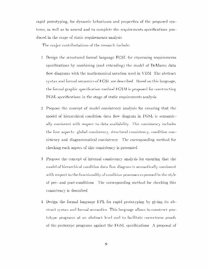
List of Figures
��� Process of requirements analysis in SFRAM � � � � � � � � � � � � ��
��� The �rst level DDFD of the system � � � � � � � � � � � � � � � � � �
��� The second level DDFD of the system � � � � � � � � � � � � � � � � �
��� The third level DDFD of the system � � � � � � � � � � � � � � � � ��
��� Graphic representation of a condition process � � � � � � � � � � � ��
��� Condition process TCS � � � � � � � � � � � � � � � � � � � � � � � � ��
��� Decomposed CDFD of TCS � � � � � � � � � � � � � � � � � � � � � ��
��� Example of an incorrect CDFD � � � � � � � � � � � � � � � � � � � �
��� Decomposed CDFD of CO � � � � � � � � � � � � � � � � � � � � � � �
��� Example of an incorrect Decomposed CDFD � � � � � � � � � � � � �
�� Example of a CDFD � � � � � � � � � � � � � � � � � � � � � � � � � �
�� An example of incorrect CDFD � � � � � � � � � � � � � � � � � � � �
��� An example of CDFD � � � � � � � � � � � � � � � � � � � � � � � � � �
���� Correct but implicit CDFD � � � � � � � � � � � � � � � � � � � � � �
���� More explicit CDFD � � � � � � � � � � � � � � � � � � � � � � � � � �
���� An example of CDFD � � � � � � � � � � � � � � � � � � � � � � � � � �
���� A disconnected CDFD � � � � � � � � � � � � � � � � � � � � � � � � �
��� Violation of global consistency � � � � � � � � � � � � � � � � � � � � ���
��� Violation of structural consistency � � � � � � � � � � � � � � � � � � ���
��� Violation of condition consistency � � � � � � � � � � � � � � � � � � ���
�

��� Violation of diagrammatical consistency � � � � � � � � � � � � � � ���
��� Data relation matrix � � � � � � � � � � � � � � � � � � � � � � � � � ���
��� Transitive closure of the Data relation matrix � � � � � � � � � � � ���
��� A condition process � � � � � � � � � � � � � � � � � � � � � � � � � � ���
��� A CDFD with a cycle � � � � � � � � � � � � � � � � � � � � � � � � � ���
��� Process of FGSL speci�cation construction � � � � � � � � � � � � � ���
��� Teacher management system �incomplete� � � � � � � � � � � � � � ���
��� Decomposed CDFD of R�T �F �Process �incomplete� � � � � � � � � ��
��� Decomposed CDFD of Total�Mark�Evaluation �incomplete� � � � ���
��� Decomposed CDFD of Research�Mark�Evaluation �incomplete� � ���
��� Teacher management system � � � � � � � � � � � � � � � � � � � � � ���
�� Decomposed CDFD of R�T �F �Process � � � � � � � � � � � � � � � ���
�� Decomposed CDFD of Total�Mark�Evaluation � � � � � � � � � � ���
��� Decomposed CDFD of Research�Mark�Evaluation � � � � � � � � ���
���� Incorrect CDFD � � � � � � � � � � � � � � � � � � � � � � � � � � � � ���
���� Incorrect condition process � � � � � � � � � � � � � � � � � � � � � � ��

Abstract
Requirements analysis is a key activity in the process of software development for
achieving satisfactory systems� The quality of requirements speci�cations directly
a�ects the quality of the developed systems� The Structured Analysis Method
�DeMarco ��Downs � has been widely used for the production of requirements
speci�cations of industry scale software systems� The speci�cations produced
using this method are comprehensible due to the notations such as diagrams
graphics and natural language etc but lack the formality� Formal methods �Jones
�� �Nielsen � try to overcome this weakness of Structured Analysis Method
by adopting mathematical notations� The speci�cations produced using formal
methods are concise and precise in general but lack comprehensibility� Therefore
there is a great need for developing a language and a method for producing
comprehensible and precise requirements speci�cations�
A Structured and Formal Requirements Analysis Method based on data �ow
analysis and rapid prototyping is introduced in this dissertation to provide a
powerful and practical approach to requirements analysis and speci�cation con�
structions� It advocates that requirements analysis must be divided into the two
stages� static and dynamic requirements analysis� The aim of the static require�
ments analysis based on data �ow analysis is to achieve precise and detailed
functional requirements with static paper models� The purpose of the dynamic
requirements analysis is to assist clients to discover more requirements through
rapid prototyping for dynamic behaviours and properties of the proposed sys�
tems as well as to amend and to complete the requirements speci�cations pro�
duced in the stage of static requirements analysis�
The major contributations of the research include�
�� Design the structured formal language FGSL for expressing requirements
speci�cations by combining �and extending� the model of DeMarco data
�ow diagrams with the mathematical notation used in VDM� The abstract
syntax and formal semantics of FGSL are described� Based on this language
the formal graphic speci�cation method FGSM is proposed for constructing
FGSL speci�cations in the stage of static requirements analysis�
�� Propose the concept of model consistency analysis for ensuring that the
model of hierarchical condition data �ow diagram in FGSL is semantic�
ally consistent with respect to data availability� This consistency includes
the four aspects� global consistency structural consistency condition con�
sistency and diagrammatical consistency� The corresponding method for
checking each aspect of this consistency is presented�
�� Propose the concept of internal consistency analysis for ensuring that the
model of hierarchical condition data �ow diagram is semantically consistent
with respect to the functionality of condition processes expressed in the style
of pre� and post�conditions� The corresponding method for checking this
consistency is described�
�� Design the formal language FPL for rapid prototyping by giving its ab�
stract syntax and formal semantics� This language allows to construct pro�
totype programs at an abstract level and to facilitate correctness proofs
of the prototype programs against the FGSL speci�cations� A proposal of
�

an approach of transforming a FGSL speci�cation into a FPL program is
discussed and demonstrated by an example�
��

DECLARATION
No portion of the work referred to in this thesis has been
submitted in support of an application for another degree
or quali�cation of this or any other university or other
institution of learning�
��

Preface
Shaoying Liu received a B�Sc and a M�Sc Computer Science degrees from Xi�an
Jiaotong University in China in ��� and �� respectively� From ��� to ��
he worked as a teaching assistant �before ��� and a lecturer at Xi�an Jiaotong
University in China� Since January ��� he has been a postgraduate research stu�
dent at the University of Manchester� During this period he has eight research
papers published and another paper accepted for publication by the following
journals and international conferences� The Journal of Systems and Software
Computer Languages � An International Journal Computer Science �Journal in
Chinese� Proceedings of ��th Annual ACM Southeast Conference ������ Pro�
ceedings of ���� ACM Symposium on Applied Computing Proceedings of �nd
Irvine Software Symposium �ISS���� Proceedings of Fifth Nordic Workshop on
Programming Environment Research ������ Proceedings of the Second Great
Lakes Computer Science Conference Proceedings of the International Confer�
ence on Systems Management ���� All of these publications are cited in this
dissertation�
Shaoying Liu is an associate member of the Association for Computing Ma�
chinery�
��

Acknowledgements
I am greatly indebted to Dr John T� Latham for his invaluable supervision of this
thesis his help and constant encouragement� His sound advice and constructive
criticism have undoubtedly improved the quality of this work�
I would like to thank Cli� B� Jones for talking with me and giving me advice
and references� I would also like to thank K�K� Lau for his instructive discussions
with me on many topics such as formal methods logic programming and formal
semantics etc�
Thanks also go to members of the Formal Methods group for their assistance
in various ways� Barney Hilken and Sean Bechhofer gave their great help to me in
mastering the computer system and discussing some interesting problems� Nax P�
Mendler and D�P� Carlisle provided satisfactory answers to my questions about
English and the LATEX manual� D�E� Rydeheard�s chatting with me always
freshen my mind�
I would like to give the special thanks to my friends Christopher John Ho�
Stuart and Shirley Ho�Stuart for their reading the whole thesis and correcting
the English and to my colleague C� P� Higgins in the university of York for his
great help in drawing the diagrams in this dissertation�
I would like to express my warmest appreciation to my Chinese friends Ying
Zhang Luopin Xu X�Y� Fu Qinyi Jin Sa and Xienfang Ye for their help in
various ways�
I acknowledge the �nancial support of the British Council and of the Chinese
��

Education Committee�
Finally a special word of gratitude goes to my wife Atsuko for her precious
help and great support and my parents for their encouragement throughout my
studies� I dedicate this work to them�
��

Part I Problems and Motivation
��

Chapter �
Why A New Method
��� Introduction
How to develop a good quality software system has been an extremely important
but di�cult research topic in computer science since people began to understand
the problem of the software crisis in the later �����s and early ����s� From
the viewpoint of software engineering software quality can be obtained only by
careful development �Pomberger ���Booch ���
This means careful attention all the way from de�ning the problem through
developing the requirements speci�cation preparing the design doing the im�
plementation and completing the veri�cation� The requirements analysis for
the construction of requirements speci�cations is the key activity for successful
developments of systems �Shemer � �Methlie ��� Without good quality of spe�
ci�cations the people charged with developments will have no �rm idea of the
needs of the would�be users of the systems�
The structured system analysis methodology provides us with a way of repres�
enting and understanding complex systems and this allows us to work within our
human limitation� Two di�erent sorts of methods for system analysis have been
developed under the name of structured system analysis methodology Informal
��
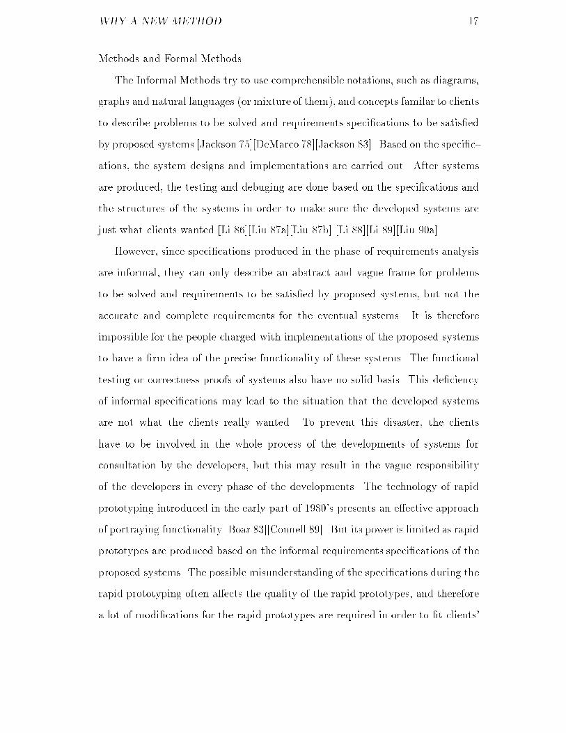
WHY A NEW METHOD �
Methods and Formal Methods�
The Informal Methods try to use comprehensible notations such as diagrams
graphs and natural languages �or mixture of them� and concepts familar to clients
to describe problems to be solved and requirements speci�cations to be satis�ed
by proposed systems �Jackson ���DeMarco ��Jackson ��� Based on the speci�c�
ations the system designs and implementations are carried out� After systems
are produced the testing and debuging are done based on the speci�cations and
the structures of the systems in order to make sure the developed systems are
just what clients wanted �Li ���Liu a��Liu b� �Li ��Li ���Liu ��a��
However since speci�cations produced in the phase of requirements analysis
are informal they can only describe an abstract and vague frame for problems
to be solved and requirements to be satis�ed by proposed systems but not the
accurate and complete requirements for the eventual systems� It is therefore
impossible for the people charged with implementations of the proposed systems
to have a �rm idea of the precise functionality of these systems� The functional
testing or correctness proofs of systems also have no solid basis� This de�ciency
of informal speci�cations may lead to the situation that the developed systems
are not what the clients really wanted� To prevent this disaster the clients
have to be involved in the whole process of the developments of systems for
consultation by the developers but this may result in the vague responsibility
of the developers in every phase of the developments� The technology of rapid
prototyping introduced in the early part of ����s presents an e�ective approach
of portraying functionality �Boar ���Connell ��� But its power is limited as rapid
prototypes are produced based on the informal requirements speci�cations of the
proposed systems� The possible misunderstanding of the speci�cations during the
rapid prototyping often a�ects the quality of the rapid prototypes and therefore
a lot of modi�cations for the rapid prototypes are required in order to �t clients�

WHY A NEW METHOD �
true requirements� Eventually the rapid prototyping is not rapid and the cost is
not so low �Connell ���
The Formal Methods are proposed to attempt to overcome the weaknesses
of informal methods by basing the requirements analysis and developments on
mathematics� The functional speci�cations of the proposed systems are construc�
ted by using mathematical notations through requirements analysis� Since the
mathematical notations have precise semantics the speci�cations can describe
precise requirements and build the �rm foundation for further developments of
the proposed systems� The further developments including implementations and
veri�cations are totally responsible for the requirements speci�cations� The use
of formal methods in the development of software systems has been advocated by
many see for instance �Dijkstra ���Jones ���Gries ���Reynolds ���Hehner ��
�Gordon� ��Liskov et al ���Turski �� The signi�cant advances which formal
methods have achieved or attempt to achieve are the capacity of establishing
precise and concise speci�cations a rigorous development process and the capab�
ility of proving the correctness of the developed systems �Liu ��b��
However there are several reasons to prevent formal methods from being
popular in academy and industry for requirements analysis and system devel�
opments� The �rst one �also the most serious one� is that formal speci�cations
are di�cult to understand in general especially for clients� The communication
between clients and developers via the speci�cations then becomes an extremely
serious problem �Liu ��c��McDermid ��a�� Consequently the quality of achieved
requirements speci�cations is seriously a�ected �Leveson ��� The second reason
is that formal speci�cations cannot re�ect the dynamic properties and behaviour
of the proposed systems� Therefore It is impossible for them to express all the
requirements of clients for the proposed systems� The third one is that the cost
of the correctness proofs of large systems is extremely high and the rigorous

WHY A NEW METHOD ��
process of developments of systems is di�cult to be performed in practice �Hayes
���Barden ���� Therefore formal methods so far are more suitable for abstract
design of systems than for requirements analysis�
To overcome the de�ciencies of the existing informal methods and formal
methods for requirements analysis in general there is a great need of propos�
ing a new method �and a language to be used in this method�� It should make
good use of the existing informal models for representing problems and require�
ments and the mathematical notations used in the existing formal methods� The
requirements speci�cations produced using this new method should be both com�
prehensible and precise and the dynamic properties and behaviour requirements
of systems should also be able to be discovered�
According to this principle a structured formal requirements analysis method
based on data �ow analysis and rapid prototyping is introduced in this disserta�
tion� This new method will be described in detail from next chapter� Before that
we �rst need to review and to compare the existing popular informal methods
and formal methods �or notations� in order to indicate the concrete target this
new method should reach�
��� Informal Methods
����� DeMarco�s Approach
Tom DeMarco �rst proposed the model of data �ow diagrams to be a method and
language for requirements analysis �DeMarco �� A data �ow diagram shows the
connections between processes data �ows and �les� A data �ow is information
in motion� It may cause something to happen when it is received� A process
transforms input data �ows into output data �ows� When a data �ow stops
waiting to be used at another time it becomes a �le� In DeMarco data �ow

WHY A NEW METHOD ��
diagram a process is represented by a bubble� Lines with arrows called arcs
point from one process to another to show data �ows and are usually labeled by
a English word or letter� A straight line is used to represent a �le� DeMarco data
�ow diagram provides the hierarchy mechanism to �t into complex requirements
analysis� The hierarchical structure in data �ow diagrams is constructed by
decomposing each upper level bubble into a sub data �ow diagram which re�ects
the details of how to transform their input data �ows into their output data �ows�
The function of each bottom level process is usually speci�ed using structured
English�
In addition to the data �ow diagrams a data dictionary is designed for de�
�ning data �ows components of data �ows �les and processes occurring in the
data �ow diagrams� Data �ow diagrams and the data dictionary have to be con�
sidered together� Without a data dictionary the diagrams lack rigor� without the
diagrams the data dictionary is of no use to anyone� The correlation between
the two is that there is one data dictionary entry for unique data �ow �le and
each process occurring in the diagrams respectively�
����� SSADM
SSADM short for Structured Systems Analysis and Design Method is the UK
goverment�s standard method for carrying out the systems analysis and design
stages of an Information Technology �IT� development project� It breaks down
the work into phases which are then divided into stages� Each stage is subdivided
into steps� Each step has a list of tasks inputs and outputs as described in
�Downs ��
The characteristics of SSADM include�
� data driven approach to development�
� cross�checking between di�ering views�

WHY A NEW METHOD ��
� separation of the logical and physical aspects of development�
The three phases of SSADM are� Feasibility Analysis Design� The feasibility
phase consists of two stages Problem de�nition and Project de�nition� These
stages assess the scale of the problem and the costs and likelihood of improving
the situation�
The analysis phase includes three stages� Analysis of the current system Spe�
ci�cation of the required system and Select service level for new system� Where
the analysis phase commences an SSADM project the input is some statement
of the problem or possibility to be investigated� SSADM then acquires more in�
formation particularly during the stage of Analysis of the current system� The
following stage concentrates on establishing what a new system must achieve by
producing designs at a logical or abstract level� In a SSADM project Data Flow
Diagrams �DFDs� are used to describe the existing physical system the logical
equivalent of the existing system and the required system while Logical Data
Structuring Technique �LDST� and Entity Life Histories �ELHs� diagrams are
employed to described the data requirements� The LDST takes a static view of
the data by describing the entity relationships� The DFDs look at the move�
ment of data and the dependency of processes upon certain �ows� The ELHs
complement these perspectives by looking at how entities change over time�
The design phase consists of three stages� Detailed data design Detailed
process design and Physical design control� Initially design is done at a logical
level� It is then converted to a physical design� The data and process aspects of
the design are interleaved and cross�checked so that the �rst two stages of the
design are done more in parallel than in sequence� The last stage of the design
represents a check that the design does meet the service levels set in last stage of
analysis�

WHY A NEW METHOD ��
����� JSD
JSD short for Jackson Software Development is a systematic method for spe�
cifying and implementing computer systems especially for information systems
�Jackson ��� JSD starts with the description of the model of the real world and
then speci�es the functions of the system to be developed based on the model
of the real world� The implementation step is therefore centrally concerned with
transforming the speci�cation to make it convenient to execute� To be clear and
understandable JSD provides a series of diagrams for the development steps�
The JSD development procedure consists of the following six steps�
��� Entity action step� de�nition of the real world by the developer�
��� Entity structure step� actions performed by each entity are arranged in
their orders by time�
��� Initial model step� the description of reality in terms of entities and
actions is realized in a process model and connections between the model and
the real world�
��� Function step� Functions are speci�ed to produce the outputs of the
system�
��� System timing step� consider the process scheduling�
��� Implementation step� consider what hardware and software is or should
be provided for running the system and applies the techniques of transformation
and scheduling�
The primary work related to JSD is described in �Jackson ���
����� Comparsion of Informal Methods
For requirements analysis SSADM uses the method similar to DeMarco�s ap�
proach� Both of them emphasize the function�oriented system analysis but this
analysis is directed by data �ow instead of control structure� To understand the

WHY A NEW METHOD ��
functionality of systems it is necessary to de�ne the structure and properties of
data used in the description of the system functionality �data �ow diagrams��
DeMarco�s approach uses the data dictionary to describe data which is similar
to LDST model in SSADM but lacks a model to describe the dynamic properties
and relationships of data like the Entity Life Histories �ELHs� model in SSADM�
JSD takes a fundamental di�erent principle from SSADM and DeMarco�s ap�
proach for requirements analysis� It advocates that the developer must begin
by modelling the real world� The real world is described in terms of entities
actions they perform or su�er and the orderings of those actions �to a certain
degree it is an object�oriented system analysis approach�� However a practical
di�culty in requirements analysis is how to choose entities and how many and
what kinds of actions should be de�ned before �guring out the abstract func�
tionality of the systems� Furthermore there is only mechanism available in JSD
for describing sequential actions but not for concurrent actions� Compared with
DeMarcho�s approach and SSADM this point limits the capacity of JSD� In fact
JSD is more suitable for developing the systems which mainly provide operations
on data �e�g� database systems� than DeMarcho�s approach and SSADM while
DeMarco�s approach and SSADM are more natural for requirements analysis for
general information systems�
��� Formal Methods and Notation
In this section the relevant and popular formal methods and notation are reviewed
and compared according to the principle that whether they can be used to express
the following properties of speci�cations�
� Hierarchical� a speci�cation is constructed hierarchically�

WHY A NEW METHOD ��
� Modular� a speci�cation consists of modules and the modules can be de�
scribed separately�
� Concurrent� di�erent modules perform at the same time�
� Extendable� description of each module can be extended without much
a�ecting the previous description�
� Abstract� a speci�cation is not concerned with detailed representation�
� Consistent� there is no semantical contradiction in a speci�cation�
� Sound� a speci�cation is constructed based on the mathematical notation
and can be the basis for correctness proofs of implemented programs�
The hierarchical modular concurrent and extendable are the usiability proper�
ties of speci�cations while the abstract consistent and sound are the technical
properties of speci�cations�
����� VDM
VDM �Vienna Development Method� is a denotational model�based approach
�Bj�rner ���Jones ��� In VDM speci�cations are constructed around abstract
states which are models de�ned in terms of data objects such as sets maps
and lists� Operations on these state�like objects are speci�ed by pre� and post�
conditions� The pre�condition is a predicate over the initial state of the operation
and can be used to limit the cases in which the operation has to be applicable�
The post�condition is a predicate of two states� it speci�es the �input�output�
relationship between the initial and �nal states of the operation�
Design in VDM proceeds by data rei�cation and operation decomposition�
Data rei�cation is the process by which abstract objects are re�ned into types
which are available in the implementation language� Operation decomposition

WHY A NEW METHOD ��
is the process by which implementations for operations are developed in terms
of the primitive statements available in the programming language �Latham ����
In both processes proof obligations are generated and are discharged to show
that the implementation satis�es the speci�cation� For operation decomposition
typically there will be a decomposition proof rule for each control construct in the
implementation language� These decomposition proof rules show the conditions
under which combinations of code and speci�cations of sub�components provide
a correct decomposition of a given speci�cation�
Hierarchical� There is no well�designed mechanism to build a hierarchy of
operations� Each operation can be described in terms of auxiliary functions thus
omitting the more complex details from the top level descriptions�
Modular� A speci�cation is not modular but a collection of operations�
Concurrent� There is no mechanism for describing concurrent execution of
di�erent operations�
Extendable� The pre� and post�conditions of operations are extendable and
more operations can be added to the previous speci�cations�
Abstract� The pre� and post�conditions are abstract and the data types
used in the predicates are abstract� They are usually not concerned with the
implementation�
Consistent� Whether a speci�cation is consistent can be checked by using
the obligations of operations and functions as well as the decomposition rules�
Sound� The notation is mathematically based and the rules for correctness
proofs for re�nements are provided� Therefore the correctness of an implement�
ation against its speci�cation can be proved�
Some signi�cant work on VDM are described in �Bj�rner ��Jones a� �Jones
b��Minkowitz ��Bear ��Milne ��Ah�Kee ���

WHY A NEW METHOD ��
����� RAISE
RAISE �Rigorous Approach to Industrial Software Engineering� is a systematic
development method �Bj�rner ���Prehn ��Nielsen � which is a combination
of useful aspects of VDM with well�researched areas of algebraic speci�cation
techniques and CSP �Hoare ��� It provides two languages RAISE Speci�ca�
tion Language �RSL� and RAISE Development Language �RDL�� As we are only
interested in the speci�cation language RDL will not be discussed�
RSL preserves many of the well�known features of VDM notations� the usual
prede�ned operations on the various sorts of abstract data types imperative
features explicit function de�nitions and implicit de�nitions etc� But RSL di�ers
radically from VDM notation in providing a powerful structuring mechanism in
treating types in a rather more general way than the well�know VDM types and
in gracefully incorporating concurrency�
Hierarchical� A speci�cation is a collection of module declarations� Modules
are the means by which to decompose speci�cations into comprehensible and re�
usable units� A module is basically a named collection of declarations� A module
M� can be used to de�ne another module M� meaning that the declarations of
M� are used to de�ne M��
Modular� In RSL there are two kinds of modules� object and scheme� An
object is essentially a named model chosen from a class of models represented by
some class expression� A scheme is a named class expression� Each module is
described separately�
Concurrent� RSL o�ers both abstract notions of concurrency expressed as
trace assertions and operational notions expressed as CSP programs�
Extendable� One can in RSL build a class expression in successive steps at
each step adding declarations with an operator named extend�
Abstract� The description of the system using RSL is abstract due to the

WHY A NEW METHOD �
mathematically based notations�
Consistent� There is no mature technology for ensuring the consistency of
speci�cations�
Sound� RSL is mathematically based and the rules for re�nements are provided�
Therefore the correctness proof of an implementation can be realized�
����� B Method
The B Method is a formal software development process for the production of
highly reliable portable and maintainable software which is veri�ably correct
with respect to its functional speci�cation �Abrial ���� The method uses the
Abstract Machine Notation �AMN� as the language for speci�cation design and
implementation within the process� The method is supported over the entire
spectrum of activities from speci�cation to implementation by a set of computer�
aided tools �
Hierarchical� Speci�cations are organized and presented as Abstract Ma�
chines �Abrial �� formal state�based models immediately processible by the B
Toolkit� Abstract Machine clauses provide a list of state variables an invari�
ant constraining and relating the state variables and operations on the state
variables� Operations are speci�ed in a pre�post condition style� state variable
changes are abstractly speci�ed as substitutions of new values for old under
stated pre�conditions� Abstract Machines may be parametrised so that instances
of machines can be reused in the incremental construction of more complex ma�
chines�
The variables of a constructed machine include the collection of variables from
each of the used machines� the invariant includes the conjunction of the invari�
ants from each individual machine� New variables can be introduced and new
invariant conditions can be imposed� The initialisations from the used machines

WHY A NEW METHOD �
are inherited�
An operation from a used machine may be promoted in which case it becomes
an operation of the new machine� Also new operations can be constructed from
existing operations�
Modular� Each Abstract Machine may be speci�ed separately�
Concurrent� Operations from di�erent Abstract Machines can be put to�
gether using a speci�c operator to operate in parallel�
Extendable� Each Abstract Machine can be extended by adding more vari�
ables and operations� Each operation can also be extended by enriching its post�
condition�
Abstract� The description of the system using the B Method is abstract due
to the mathematically based notations�
Consistent� Proof of internal consistency of an Abstract Machine can be
achieved by using the proof obligations provided by the B Method� It requires
demonstration that within the contex of the machine each machine operation
when invoked within its stated pre�condition maintains the invariant on the state
variables once the latter have been initialised to establish the invariant�
Sound� The B Method is mathematically based and the rules for correctness
for re�nements are provided� Therefore the correctness proof of an implementa�
tion against its speci�cation can be performed�
����� Z
Z is a formal notation for system speci�cation construction �Spivey � �Spivey
���King ���� In Z a speci�cation is decomposed into pieces called schemas� Each
piece can be linked with a commentary which explains informally the signi�cance
of the formal mathematics� Schemas are used to describe both static and dynamic
aspects of a system� The static aspects include�

WHY A NEW METHOD ��
� the states it can occupy�
� the invariant relationships that are maintained as the system moves from
state to state�
The dynamic aspects include�
� The operations that are possible�
� the relationship between their inputs and outputs�
� the changes of state that happen�
Hierarchical� In general there is no well�designed mechanism to build the
hierarchy of Schemas� But schemas can be combined to construct more powerful
schemas conditionally� Thus the upper level descriptions can be expressed with
lower level schemas in some cases�
Modular� A speci�cation is not modular but a collection of schemas�
Concurrent� There is no mechanism available in Z at present to describe
the concurrency�
Extendable� The description of each schema is extendable�
Abstract� The description of every schema is abstract due to the abstract
data types such as set types cartesian product types and schema types as well
as the �rst order logic�
Consistent� There is no mature technique for checking the consistency of
speci�cations so far�
Sound� The notation is mathematically based� Therefore the speci�cation
provides a basis for correctness proof of design and implementation�

WHY A NEW METHOD ��
��� Outline
This dissertation is organized into four parts� Problems and Motivation
Static Requirements Analysis Dynamic Requirements Analysis and
Summary� Each part includes some chapters to address the particular issues�
In the �rst part Problems and Motivation there are two chapters� The
�rst chapter is Why A New Method� It analyzes the general problems with
existing informal and formal methods for requirements analysis and speci�cation
constructions by reviewing and comparing these methods� The motivation of
introducing a new method is derived from this analysis� The second chapter is
Introduction of New Method for Requirements Analysis� It brie�y intro�
duces the philosophy of the new method SFRAM by investigating three aspects�
process of requirements analysis using SFRAM design rational of the language
FGSL for the construction of requirements speci�cations in the stage of static
requirements analysis and design rational of the language FPL for producing
prototype programs in the stage of dynamic requirements analysis�
The second part Static Requirements Analysis includes chapter � � � and
�� Chapter � is Formal Graphic Speci�cation Language� It describes the
abstract syntax and formal semantics of the language FGSL� Chapter � is Model
Consistency Analysis� It describes the purpose of introducing this consistency
and solutions for guaranteeing this consistency for speci�cations� Chapter � is
Internal Consistency Analysis� It describes the de�nition of this consistency
and the solution for ensuring this consistency for speci�cations� Chapter � is
Philosophy of FGSM� It introduces the formal graphic speci�cation method
FGSM based on the language FGSL described in chapter �� A reasonably large
example is given to demonstrate how the FGSM is applied in practice�
The third part Dynamic Analysis includes chapter only� Chapter is
Formal Language for Rapid Prototyping� The abstract syntax and formal

WHY A NEW METHOD ��
semantics of the language FPL for constructing prototypes are described� The
principle of producing a prototype using FPL from the corresponding FGSL spe�
ci�cation is addressed with an example�
The last part Summary includes chapter which is Conclusions� It sum�
marizes the results achieved in this dissertation by emphasizing the three aspects�
original contributions comparsion with the related informal and formal methods
and the further research�

Chapter �
Introduction of New Method for
Requirements Analysis
As described in the introduction of chapter � informal methods for requirements
analysis lack the formality and consequently the requirements speci�cations can�
not provide precise information for further development of systems� Formal meth�
ods overcome these disadvantages by using the mathematical notation but build
the obstacle to communication between clients and developers� This obstacle ser�
iously prevents formal methods from being applied widely in industry� Without
breaking through this obstacle the bright idea of formal methods will become a
sweet dream�
In this dissertation a structured formal method for requirements analysis is
described� It is an e�ort to realize the bright idea of fomal methods� We simply
call this new method SFRAM �short for Structured and Formal Requirements
Analysis Method�� It advocates that requirements analysis must be divided into
the two stages� static and dynamic requirements analysis� The aim of static
requirements analysis is to achieve precise and detailed functional requirements
with static paper models� The purpose of the dynamic requirements analysis
is to assist clients to discover more requirements for dynamic behaviours and
��

NEW METHOD SFRAM ��
proterties of the proposed systems as well as to amend and to complete the
requirements speci�cations produced in the stage of static requirements analysis�
This philosophy is expressed in Fig ��� in which the broken lines with short dash
indicate the communication the double broken lines with long dash represent
�production� and the solid lines represent the compulsory actions�
In the stage of static requirements analysis SFRAM not only emphasizes the
importance and necessity of the use of formal notation but also the use of the
existing structured analysis method and graphic notation� The graphic notation
is comprehensible to clients� The formal notation is for achieving the precise
semantics of the graphic notation and the precise functional requirements� In
SFRAM a formal graphic speci�cation method FGSM for short is used for the
construction of requirements speci�cations� The speci�cations are expressed in
the formal graphic speci�cation language FGSL� The FGSL is created by com�
bining �and extending� the model of DeMarco data �ow diagrams with the math�
ematical notation used in VDM�
In the stage of dynamic requirements analysis SFRAM uses the approach of
rapid prototyping� Prototypes of the proposed systems are built based on the
the corresponding FGSL speci�cations� A formal language called FPL �short
for Formal Prototyping Language� is provided for constructing prototypes� It is
designed by combining �and extending� Pascal�like languages with the mathem�
atical notation used in VDM �also in FGSL�� FPL programs should be proved to
be correct against their FGSL speci�cations� Only based on this assumption can
the objective of rapid prototyping in SFRAM be realized� To reduce the cost of
system developments we prefer to build the evolutionary prototypes rather than
throwaway ones�

NEW METHOD SFRAM ��
Real World
(1) Formal Requirements Specifications
(2) Prototypes
Dynamic Requirements Analysis
Static Requirements Analysis
Using FGSM
Using Rapid Prototyping
Figure ���� Process of requirements analysis in SFRAM

NEW METHOD SFRAM ��
��� Design Rationale of FGSL
The language FGSL for expressing requirements speci�cations is the key issue for
introducing the structured formal method FGSM for requirements analysis� As
described above the FGSL is created by combining �and extending� the model
of DeMarco data �ow diagrams with the mathematical notation used in VDM�
There are three reasons for this design� The �rst reason is because both the
model of DeMarco data �ow diagrams is popular and the VDM is well�known in
academy and industry� The second one is because they are compatible in terms
of notation �e�g� an operation in VDM is similar to a process in DeMarco data
�ow diagrams�� The last reason is because both of them are not good enough for
expressing problems and requirements�
There are large evidence to show that the DeMarco data �ow diagrams are
popular for systems analysis and design �Beck ���DeMarco ��Gane �� �Wein�
berg ��� It is popular is because it presents an approach by which a complex
system speci�cation can be decomposed into a modular and hierarchical structure
being comprehensible and a developer and someone outside the �eld can com�
municate� The VDM becomes well�known in academy and industry is because
VDM has a well�developed mathematical notational system and proof rules for
formal proofs of speci�cations based on formal predicate logic and set theory� A
large community of researchers �both in academy and industry� experienced in
VDM exists and is currently growing �Duce ��Pedersen ��Crispin ��Schmidt
��
The concepts of process and operation are the key concepts in the model of
DeMarco data �ow diagrams and VDM respectively and both of them are used
for representing the primitive actions� Therefore the way of using pre� and post�
conditions to specify the precise functionality of operations in VDM is applicable
to processes in the model of DeMarco data �ow diagrams� Furthermore the data

NEW METHOD SFRAM ��
dictionary in the model of DeMarco data �ow diagrams is similar to the type
and variable declarations in VDM except for the lack of precision� Therefore the
formal notation used in VDM is suitable for formalizing the model of DeMarco
data �ow diagrams�
The reason why both the model of DeMarco data �ow diagrams and VDM are
not good enough for expressing problems and requirements is mainly because the
former cannot express the problems and requirements precisely and the latter
employs the notation which is di�cult for clients to understand� In detail these
de�ciencies are discussed as follows�
��� Problems with DDFD and VDM
����� Problems with DDFD
To understand the problems with the model of DeMarco data �ow diagrams
�DDFD for short� we �rst need to demonstrate how to use DDFD with an ex�
ample� The structured DDFD of expressing a training centre system is given in
Fig ��� Fig ��� and Fig ���� Each process in this structured DDFD has a number
for corresponding to its decomposition�
The training centre system is denoted by the process Training Centre in
Fig ��� and designed for training students teachers and workers� It accepts
the input data �ows Student Teacher and Worker to produce the output data
�ows Trained�Student Trained�Teacher and Trained�Worker� This gives only a
rough idea of the functionality of this system� To represent the details of trans�
forming the input data �ows of the process Training Centre into its output data
�ows we need to decompose this process into another data �ow diagram which is
given in Fig ���� The number for labelling the process Training Centre is � there�
fore its decomposed data �ow diagram given in Fig ��� is labelled by Diagram �

NEW METHOD SFRAM �
to indicate the correspondance to it�
TrainingCentre
Student
Teacher
Worker
Trained-Student
Trained-Teacher
Trained-Worker
[Diagram 0]
1
Figure ���� The �rst level DDFD of the system
In Fig ��� the process Student Registration handles the incoming data �ow
Student and builds the �le Registered�Student� The Worker Registration pro�
cesses the input data �ow Worker and builds the �le Registered�Worker� After
these two �les are created the process Courses Organization will transform the
incoming data �ow Teacher �if it is available� and the �les Registered�Student and
Registered�Worker into the output data �ows Trained�Student Trained�Teacher
and Trained�Worker� As the Courses Organization is too complicated to under�
stand we need to decompose it into another data �ow diagram which is expressed
in Fig ����
In Fig ��� the process Student Courses deals with the �le Registered�Student
and produces the output data �ow Course�Student� But if the student is not
quali�ed after having the courses the data �ow Unquali�ed�Student will be
produced and is delivered to the same process Student Courses again until he
is quali�ed� The process Teacher Courses transforms the incoming data �ow

NEW METHOD SFRAM �
[Diagram 1]
StudentRegistration
Registered-Student
CoursesOrganization
WorkerRegisteration
Teacher
Trained-Student
Trained-Teacher
Trained-Worker
Student
Worker
1.1
1.2 1.3
Registered-Worker
Figure ���� The second level DDFD of the system

NEW METHOD SFRAM ��
Teacher into the three output data �ows Ph�D�Teacher M�Sc�Teacher and B�Sc�
Teacher�The processes Ph�D Courses M�Sc Courses and B�Sc Courses then handle
these three data �ows respectively and produce the three output data �ows P�
Course�Teacher M�Course�Teacher and B�Course�Teacher as the input data �ows
of the process Training Organization� Similar to the process Student Courses the
process Worker Courses handles the �le Registered�Worker and then produces
the output data �ow Course�Worker� After all the incoming data �ows of the
process Training Organization are available it transforms them into the output
data �ows Trained�Student Trained�Teacher and Trained�Worker�
To understand further the data �ows and the processes occurring in the struc�
tured DDFD a data dictionary is necessary to build for de�ning the structure of
each data �ow and �le as well as the purpose of each process� There are many
mechanisms introduced in �DeMarco � for describing the data dictionary� But
for the sake of space we will only give an example of how to de�ne data �ows
and processes�
The data �ow Student in Fig ��� for example in the data dictionary associ�
ated with the structured DDFD of the training centre system as follows�
Student � Name � Sex � Age
where � means combination and the Student therefore is composed of the com�
ponents Name Sex and Age�
The process Training Organization in Fig ��� for example is de�ned in the
data dictionary as follows�
Process number� ����
Process Name� Training Organization
Functionality�
If the Course�Student arrives do the folloing�
Award the student a certi�cate of passing all the training courses�

NEW METHOD SFRAM ��
[Diagram 1.3]
Registered-Student
Teacher
Registered-Worker
StudentCourses
TeacherCourses
Ph.DCourses
MS.cCourses
BS.cCourses
WorkerCourses
TrainingOrganization
Trai
ned-
Stud
ent
Trained-Worker
Ph.D-Teacher
B-Course-Teacher
MS.c-Teacher
BS.c-Teacher
P-Course-Teacher
M-Course-Teacher Trained-Teacher
Course-Student
Course-Worker
1.3.1
1.3.2
1.3.3
1.3.4
1.3.5
1.3.6
1.3.7
Unqualified-Student
Figure ���� The third level DDFD of the system

NEW METHOD SFRAM ��
If one of the P�Course�Teacher M�Course�Teacher and B�Course�Teacher
arrives do all the following�
��� Award the teacher a certi�cate of passing all the training courses�
��� Provide a recommendation for the teacher to be a lecturer if his
study record is good�
If the Course�Worker arrives do all the following�
��� Award the worker a certi�cate of passing all the training courses�
��� Provide a recommendation for the worker to be a technician if his
study record is good�
This example illustrates some of the de�ciencies in DeMarco data �ow dia�
grams�
�� The model is imprecise�
In the model of DeMarco data �ow diagrams there are three aspects of
imprecision� They are data functionality of processes and semantics of the
model�
The data are imprecise because data are not de�ned by types which have
the precise meaning �e�g� sequence of natural numbers�� For example the
data ��ow� Student in the example given above is composed of Name Sex
and Age but the meanings of the Name Sex and the Age are not well
de�ned� Furthermore whether the Student denotes one student or a set of
students or a sequence of students is also not clear�
The functionality of processes is described in natural language �e�g� Train�
ing Organization in the example given above�� Therefore it might be am�
biguous� It is also impossible to provide the precise information for imple�
mentation using formal languages as there is always a gap between informal
and formal expressions�

NEW METHOD SFRAM ��
The semantics of the model is not clear due to the imprecise de�nitions of
data and functionality of processes� For example when and under what
condition the data �ow Unquali�ed�Student will loop over the process Stu�
dent Courses in Fig ��� and under what condition the data �ow Course�
Student will be produced are not precisely de�ned �it is impossible to do so
informally��
�� Di�cult to discuss consistency�
Based on the informal foundation of the model of DeMarco data �ow dia�
grams it is very di�cult to de�ne the consistency within this model� There�
fore whether there is ambiguity or contradiction in a requirement speci�c�
ation cannot be proved or checked�
�� Di�cult to be a �rm basis for Further Developments�
Further developments of systems include Implementation and veri�cation�
Because of previous de�ciencies requirements speci�cations expressed us�
ing the model of DeMarco data �ow diagrams can provide neither precise
information for implementation nor solid foundation for veri�cation�
����� Problems with VDM
VDM is not suitable for requirements analysis due to the following de�ciencies�
�� Lack of a well�designed structuring mechanism�
In VDM operations are speci�ed by pre� and post�conditions but there is
no any well�designed mechanisms to compose operations� A possible way
of doing this is to use the sequential conditional and iterative combinators
but this may encourage developers to construct programs directly rather
than speci�cations�
NEW METHOD SFRAM ��
�� Lack of suitable concepts for requirements analysis�
VDM employs the concepts of state change and function driven speci�ca�
tion construction� However these concepts are more suitable for expressing
solutions rather than problems and are di�cult for clients to understand�
Therefore the di�cult communication between clients and developers in
requirements analysis may prevent developers from obtaining the speci�ca�
tions expressing the true requirements�
�� Lack of a mechanism for expressing concurrent execution�
There is no mechanism available in VDM for expressing concurrent execu�
tion of operations� This de�ciency may prevent VDM from being applied
to the development of concurrent systems�
��� Previous Work and Capability of FGSM
Because of the problems with DDFD and VDM there is a great need to create
a new language by combining �and extending� DDFD and the formal notation
used in VDM and a method for requirements speci�cation construction using
this language� This language and the associated method should be advanced
than both DDFD and VDM in the sense of achieving good quality of requirements
speci�cations� The FGSL and FGSM in SFRAM are the language and the method
designed with the above aim� From the chapter � to � the FGSL and FGSM are
described in detail but we need to propose the capability of FGSM as the goal
to achieve� Beforehand it is necessary to understand the previous work in the
direction of formalizing the model of data �ow diagrams�

NEW METHOD SFRAM ��
����� Previous Work
Some work has been done on formalizing the model of data �ow diagrams� Mike
Adler presents an algebra to formalizes process decomposition using the DeMarco
representation scheme �Adler �� In this algebra the analyst relates the disjoint
input and output sets of a single process by specifying the elements of an in�
put�output connectivity matrix� A directed acyclic graph is constructed from
the matrix and is the decomposition of the process� T�H�Tse describes a proposal
for formalising data �ow diagrams through extended Petri nets �Tse ��� A spe�
ci�cation language known as formal data �ow diagrams is developed� Tse�s work
made more progress than Adler�s in the sense that the issue of consistency ana�
lysis for requirements speci�cations are addressed� Y� Tao provides a formal basis
for the data �ow diagrams by using the notions of diagraph and the precedence
relation �Tao ���� This work addresses the issue of consistency in process decom�
position in the similar way to Adler�s but discusses the issue of completness of
speci�cations� However all of these latest work did not develop the model of data
�ow diagrams into an approach for describing precise requirements speci�cations
as the semantics of data processes and the model are not well� de�ned�
As formal methods �nd increasing acceptance within the software industry
there is a growing body of research and user interest in the integration of struc�
tured methods and formal methods or notations� L� Semmens and G� Randell
illustrates how to translate a data �ow diagram into an outline Z speci�cation
and vice versa �Semmens ����Randell ���� The data in the data dictionary are
represented in Z speci�cations by the corresponding given sets and the associated
variable declarations� The processes are expressed by the pre� and post�conditions
in Z speci�cations� M�D� Fraser et al discuss how to bridge the gap by using Struc�
tured Analysis �SA� and VDM as surrogates for informal and formal languages
respectively �Fraser ���� Two approaches are presented for integrating the two�

NEW METHOD SFRAM ��
The �rst approach uses the SA model of a system �data �ow diagram� to guide the
analyst�s understanding of the system and the development of the VDM speci�c�
ations� The second approach proposes a rule�based method for generating VDM
speci�cations from a set of corresponding SA speci�cations �data �ow diagrams��
However their way of doing the integration is to use the model of data �ow
diagrams and Z or VDM sequentially� That is at the �rst stage use the approach
of structured data �ow diagrams to produce an informal speci�cation and then
transform it into a formal speci�cation� Unfortunately this does not make good
use of the advantages of structured methods �comprehensible� and formal meth�
ods �precise�� This approach also contributes nothing for developing the model of
data �ow diagrams into a language for describing precise requirements speci�ca�
tions� The semantic consistency in data �ow diagrams is also an open problem�
The eventual formal speci�cations are still di�cult for clients to understand and
to use as a formal contract with developers� We believe that choosing a proper
way to combine the structured data �ow diagrams and formal notations is not
only for achieving precision of requirements speci�cations but also for exploring
the formal semantics of data �ow diagrams addressing consistency of speci�ca�
tions and improving the comprehensibility of formal speci�cations �Liu ��a��Liu
��b� �Liu ��c��Liu ��d��Liu ��e��Liu ����
����� Capability of FGSM
The FGSM should take a radical step to formalize the model of DeMarco data
�ow diagrams to provide a more suitable method for achieving good quality of
requirements speci�cations and to overcome the weakness of VDM� According to
this principle we propose that FGSM should possess the following capability�

NEW METHOD SFRAM ��
�� Possessing a well�designed structured analysis mechanism� Using FGSM a
complex system should be decomposed into a series of sub�systems� Cor�
respondingly the speci�cation of the complex system should be expressed
as a set of related sub�speci�cations which has a hierarchical structure and
is comprehensible�
�� Providing veri�ed analysis approach� Veri�ed analysis should uses the
concept of consistency checking as an approach of guaranteeing the cor�
rectness of analysis steps� Therefore the errors in analysis can be detected
before further work is undertaken�
�� Being precise and concise� Mathematical notation such as abstract data
types as well as the structure of pre� and post�conditions for specifying
the functionality of operations in VDM should be employed to achieve the
precision and conciseness of requirements speci�cations� Therefore precise
information can be provided for implementations�
�� O�ering a basis for program veri�cation� Speci�cations produced using
FGSM should be a �rm basis for the correctness proofs of implemented
programs�
�� Possessing good understandability� The model of data �ow diagrams should
be employed to keep the good understandability of requirements speci�ca�
tions
��� Design Rationale of FPL
To be precise in description later we use prototype system and prototype program
to mean the prototype in the dynamic sense and static sense respectively� The
reasons why we design this new language for rapid prototyping based on the

NEW METHOD SFRAM �
corresponding FGSL speci�cations rather than using existing high level languages
�e�g� Pascal C Lisp etc� are as follows�
�� To execute explicit speci�cations directly�
A FGSL speci�cation is usually not executable due to implicit expressions
in pre� and post�conditions of terminal condition processes �this fact will
be seen in chapter ��� If these implicit expressions can be re�ned into
a combination of explicit expressions which is executable the cost of time
and money for building a prototype system based on this FGSL speci�cation
will decrease�
�� To simplify the correctness proofs of prototype programs�
Consider the purpose of building prototypes we can understand that only
after proving the correctness of the prototype programs against their FGSL
speci�cations are the results of performing the prototype systems useful
for clients to propose more requirements or to amend the current require�
ments� Using the similar abstract data types in the language for construct�
ing prototype programs to those in FGSL will simplify the process of the
proofs� For example a sequence of natural numbers in a FGSL speci�cation
is implemented by a link of integers in the language �such as Pascal� for
constructing the prototype program will cause more di�culties during the
correctness proof of the prototype program than implemented by the same
sequence of integers �if allowable��
�� To oblige developers of prototypes to consider the correctness of the proto�
type programs throughout the whole process of programming�
It is not necessary to consider the correctness proofs during programming
using the existing high level languages as there is no such a requirement
by syntax and semantics� The correctness proofs are usually done after the

NEW METHOD SFRAM �
programs are completed� This process may cause high cost of program pro�
duction as serious mistakes occurring at an early stage may not be found
until the whole system is completed� Therefore it will be ideal for the
syntax of the prototype programming language to oblige developers to con�
sider the correctness of prototype programs throughout the whole process
of programming�
There is no suitable high level languages to satisfy the above requirements so
far to my knowledge� Therefore we need to design the new formal language FPL
to realize these advantages�

Part II Static Requirements Analysis
��

Chapter �
Formal Graphic Speci�cation
Language
To achieve the goal of creating FGSM with the capability described in section
����� we need to take a proper approach of combining DDFD with VDM� The
purpose of this combination is to create the mathematical notation FGSL �Formal
Graphic Speci�cation Language� to be used in FGSM� The principle of this com�
bination is to use DDFD as the main frame of a whole speci�cation and to use
the notation in VDM for specifying the functionality of processes in the DDFD�
This principle is realized by doing the following�
�� Introduce types and variables�
As discussed in section ����� the concept of data used in DDFD is not
precise to understand it is therefore necessary to introduce variables to
replace data and to de�ne each variable with a type� We are using exactly
the same types available in VDM �Jones �� �eg� set sequence� for de�ning
variables in FGSL� The relationship between data variables and types are
investigated�
�� Introduce condition processes�
��

FORMAL GRAPHIC SPECIFICATION LANGUAGE ��
A condition process is a process of DDFD with a pre�condition which should
be satis�ed by the input variables of the process before its execution �or
whatever terminology we will use to indicate its performance�� In FGSL we
empoly condition processes to replace processes of DDFD� The purpose of
doing this is trying to express the functionality of every process in DDFD
eventually by its pre� and post�conditions�
�� Specify post�conditions for bottom level processes�
In order for a whole FGSL speci�cation to be expressed precisely each
bottom level process of DDFD is given a post�condition which should be
satis�ed by the output variables of the process after its execution� The
post�conditions of upper level processes can be generated based on its de�
composition�
�� Allow �exclusive or� relationship between input or output variables�
As input variables of a process are all required for executing the process in
DDFD it is not powerful enough to model directly some cases in the real
world in which a process requires either some input variables or some other
input variables but not both for its execution� Therefore we allow this case
in FGSL by specifying explicitly �exclusive or� relationship between input
or output variables�
�� Adopt appropriate logic�
Since the �exclusive or� relationship between input or output variables for
a condition process in FGSL is allowed the classical logic �two value� is not
suitable for expressing the semantics of FGSL speci�cations� The extended
logic which is used in VDM is employed in FGSL�
�� De�ne formal semantics�

FORMAL GRAPHIC SPECIFICATION LANGUAGE ��
The precise semantics of speci�cations is de�ned by using the approach of
axiomatic semantics�
� Dismiss the �le notation�
As the �le notation in DDFD can be realized with a condition process it is
not used in FGSL for achieving the precise semantics of FGSL speci�cations�
Based on this formal foundation of FGSL the model consistency and the
internal consistency of FGSL speci�cations are addressed� Both of these are
used for ensuring the quality of requirements analysis� The model consistency
is for guaranteeing that the model of hierarchical condition data �ow diagram
in FGSL is semantically consistent with respect to data availability while the
internal consistency is for guaranteeing the functionality of condition processes
expressed in the style of pre� and post�conditions within this model is semantically
consistent�
This chapter focus on the detailed description of combining DDFD with VDM
to establish the formal foundation of FGSL in syntax and semantics� Chapter
� and chapter � address the model consistency and the internal consistency of
speci�cations respectively� Chapter � presents a complete example of using FGSL
to demonstrate the philosophy of FGSM for requirements analysis of software
systems and the corresponding speci�cation constructions�
��� Syntactic Structure of FGSL Speci�cations
At the heart of a FGSL speci�cation is a hierarchical condition data �ow dia�
gram� A condition data �ow diagram CDFD for short consists of variables and
condition processes� Variables are typed and used to represent data and asso�
ciated with condition processes� Each upper level condition process possesses a

FORMAL GRAPHIC SPECIFICATION LANGUAGE ��
decomposition which is another CDFD and spells out its detail� Each bottom
level condition process is speci�ed by giving the pre� and post�conditions�
To express such a hierarchical condition data �ow diagram it is essential
to introduce the type declaration and variable declaration mechanism in FGSL
speci�cations� The whole speci�cation is organized as a sequence of condition
process de�nitions which corresponds to a hierarchical condition data �ow dia�
gram and each de�nition may include type declaration variable declaration and
functionality description� The syntactic structure of a speci�cation is as follows�
CP�de�nition�
CP�de�nition�
���
CP�de�nitionn
where CP�de�nitioni �i�����n� denotes the ith condition process de�nition�
Each condition process de�nition possesses the following form�
Name ��Parent�name�
�TYPE�
�Type Declaration�
�INV�
�Data Invariant�
�VAR�
�Variable Declaration�
FUN
Functionality
�COM�
�Comment�
END�Name
where we use the square brackets �A� to mean that the symbol A is either appear

FORMAL GRAPHIC SPECIFICATION LANGUAGE ��
or not�
In this description the Name which is a compulsory part indicates the name
of the condition process to be de�ned and the Parent�name which is optional
indicates the name of its parent condition process �this concept will be de�ned
in section ������� The Parent�name is designed for improving the readability
of speci�cations as the parent condition process de�nition can be easily found
through it when the current condition process is speci�ed or read�
The TYPE is a key word which indicates that the type declarations are fol�
lowed� The Type Declaration is a sequence of type declarations and each of them
possesses the form�
Identi�er � T
where Identi�er denotes the name of the type to be de�ned T is a kind of type
which is one of basic type set type sequence type map type and composite type�
All of these types are borrowed from VDM�
The INV is a key word which indicates that the data invariants are followed�
The Data Invariant is a sequence of predicates describing the properties of the
values of some types and relationships between the values of di�erent types� These
properties and relationships are maintained throughout the whole performance
of systems�
The VAR is another key word which indicates that the variable declarations
are followed� The Variable Declaration is a sequence of variable declarations and
each of them has the form�
Variable � TI
where Variable denotes a variable �A sequence of characters starting with a Eng�
lish letter� and TI is either a type identi�er representing a de�ned type or a type
similar to T in the type declaration form above�

FORMAL GRAPHIC SPECIFICATION LANGUAGE ��
The FUN is a key word to indicate that the functionality description is fol�
lowed� The Functionality is a compulsory part of a condition process de�nition�
Di�erent kinds of condition processes have the di�erent functionality descrip�
tions� For an Upper level condition process to be de�ned the Functionality part
is a condition data �ow diagram which spells out its details while for a bottom
level condition process this part is a formal speci�cation in the style of pre� and
post�conditions� Every CDFD in a whole speci�cation except the top level one
is a decomposition of some other condition process� As there is no any condi�
tion process in the speci�cation to be decomposed into the top level CDFD �may
be only a condition process� the Name of the �rst condition process �which is
assumed� which takes the top level CDFD as its Functionality part is always
TOP�
The COM is a key word to indicates that the comment is followed� The
Comment is used for explaining the functionality of the condition process in
whatever way as users like in order to help the understanding of the formal
de�nition of the functionality�
Finally the END�Name indicates the end of the de�nition of the condition
process whose name is Name�
The above description gives a picture of the syntactic structure of a FGSL
speci�cation� But to understand a FGSL speci�cation in detail each part in this
syntactic structure needs to be discussed� This discussion will start from next
section�
��� Data� Variables and Types
A datum represents a piece of information in the real world� Data can be bound to
variables� For example a student�s information such as name age and education
etc� is data which can be bound to the variable Student� A worker�s salary is data

FORMAL GRAPHIC SPECIFICATION LANGUAGE ��
which can be bound to the variable Salary and all the students� names of one
class is data which can be bound to the variable ALLStudents� Since di�erent
information in the real world may have di�erent properties and structures the
data representing them must be distinguished in order to deal with them properly�
This can be done by declaring variables on types and data is a value of a type
and all the data in one type are allowed to be bound to the declared variables
on it� Unlike procedural programming languages variables are not considered to
be a memory store which holds di�erent values at di�erent times� A variable is
simply a way of identi�ng data and de�ning how data �ows through a system� In
order to achieve precision and conciseness of functionality description of condition
processes we employ all the abstract data types and the associated operations
available in VDM �Jones �� as the types and operations available in FGSL to be
used�
The following is an example of variable declarations for Student Salary and
ALLStudents with the associated type declarations�
TYPE
Studentinf � compose Studentinf of
name � seq of char�
age � N �
university � seq of char�
end�
Studentnames � seq of string�
string � seq of char�
VAR
Student � Studentinf �
Salary � N �
ALLStudents � Studentnames�

FORMAL GRAPHIC SPECIFICATION LANGUAGE �
where the symbols used here and later in this chapter correspond to similar ones
in VDM and are explained in Appendix A�
Based on this principle we can de�ne the concept� �available� which is basic
and necessary for the description of data �ow�
De�nition ��� �available� Data is available through a variable if this data
belongs to the type of this variable and there is one action which binds this data
to this variable� Otherwise we say no data is available through this variable and
this variable is unde�ned�
The action which binds data to variables is �ring of condition processes which
will be discussed later in section ������
Let x be a variable� Then we use the predicate AV L�x� to represent the avail�
ability of data through x� If data is available then AV L�x� � true� Otherwise
AV L�x� � false and x is unde�ned�
Data expressions represent more complex conditions on the availability of
data� We use the following de�nitions�
De�nition ��� �data expression� Let D � fa� a� ��� ang be a set of variables
then
�� ai is a data expression i � ����n�
�� If X and Y are data expressions then X � Y X � Y are data expressions�
X�Y means either X or Y but not both is required and X�Y means both X
and Y are required� Before formally de�ning the meaning of data expressions we
extend the de�nition of the AV L predicate onto the set of all data expressions as
follows �using the exclusive disjunction operator � and the conjunction operator
� in classical logic��
AV L�X � Y � �� AV L�X� � AV L�Y �
AV L�X � Y � �� AV L�X� � AV L�Y �
AV Lf g �� false�

FORMAL GRAPHIC SPECIFICATION LANGUAGE �
For the two data expressions X and Y we de�ne X � Y i� AV L�X� ��
AV L�Y �� Based on this extension X � Y and X � Y are formally de�ned as
follows�
X � Y �
�������������
X if AV L�X� � �AV L�Y �
Y if AV L�Y � � �AV L�X�
f g otherwise
X � Y �
�����������������������������������������������������������
fX�Y g if X and Y are variables
and AV L�X� �AV L�Y �
fXg � Y if X is a variable and Y is a
non�single variable data expression
and AV L�X� �AV L�Y �
X � fY g if X is a non�single variable
data expression and Y is a
variable and AV L�X� �AV L�Y �
f g otherwise
Some useful properties of data expressions are given by the following theorems�
�Theorem ���� Let X and Y be any two data expressions� Then we have
the following properties�
��� X � Y � Y �X
��� X � Y � Y �X
��� X �X � f g
��� X �X � X
Proof� we only give the proof of property ��� as the proofs of property ���
��� and ��� are similar� Since
AV L�X � Y � �� AV L�X� � AV L�Y �
�� AV L�Y � � AV L�X�

FORMAL GRAPHIC SPECIFICATION LANGUAGE ��
�� AV L�Y �X��
therefore X � Y � Y �X�
��
�Theorem ���� Let X Y and Z be any three data expressions� Then we
have the following properties�
��� �X � Y �� Z � X � �Y � Z�
��� �X � Y �� Z � X � �Y � Z�
Proof� as for theorem ��� we only give the proof of property ���� Since
AV L��X � Y �� Z� �� AV L�X � Y � � AV L�Z�
�� �AV L�X� � AV L�Y �� � AV L�Z�
�� AV L�X� � �AV L�Y � � AV L�Z��
�� AV L�X� � AV L�Y � Z�
�� AV L�X � �Y � Z���
therefore �X � Y �� Z � X � �Y � Z��
�
�Theorem ���� Let X Y and Z be any three data expressions� Then we
have the following property�
�X � Y �� Z � �X � Z�� �Y � Z�
Proof� since
AV L��X � Y �� Z� �� AV L�X � Y � �AV L�Z�
�� �AV L�X� � AV L�Y �� � AV L�Z�
�� �AV L�X� �AV L�Z�� � �AV L�Y � �AV L�Z��
�� AV L�X � Z� � AV L�Y � Z�
�� AV L��X � Z�� �Y � Z���
therefore �X � Y �� Z � �X � Z�� �Y � Z��
�
�The symbol� indicates the end of a proof of a theorem �or similar�� and the resumptionof normal text�

FORMAL GRAPHIC SPECIFICATION LANGUAGE ��
Note that there is no �X �Y ��Z � �X �Z�� �Y �Z� as the distributivity
of � over � is not applicable in general�
We let� have higher precedence than � so that X�Y �Z means �X�Y ��Z�
Furthermore there are two notions which are data conjunction and disjunctive
normal form often to be used later�
De�nition ��� �data conjunction� disjunctive normal form� A data ex�
pression is called a data conjunction if it is of the form y�� y�� ��� � yn �n � ��
and each yi �i � ����n� is a variable� A data expression is in disjunctive normal
form if it is of the form X� �X� � ��� �Xm �m � �� and each Xj �j�����m� is a
data conjunction�
Now we can discuss the de�nition of a hierarchical condition data �ow diagram
based on the concept of data expression�
��� Hierarchical Condition Data Flow Diagram
To de�ne a hierarchical condition data �ow diagram precisely we need to start
with the discussion on condition processes�
����� Condition Process
A condition process is an atomic component of a hierarchical condition data �ow
diagram� As described informaly in the begining of this chapter it is a process of
DeMarco data �ow diagram with a pre�condition� Formally a condition process
is de�ned by the following two de�nitions�
De�nition ��� �condition� Let R � fr� r� ��� rng be a set of relation expres�
sions then
�� ri true false are conditions where i � ����n

FORMAL GRAPHIC SPECIFICATION LANGUAGE ��
�� Suppose c� c� are conditions then
c� � c� c� c� �c� c� �� c� c� �� c� �c�� are conditions
�� If x is a variable and c is a condition and S is a set then x�S �c and �x�S �c
are conditions
where the operators � � �� and �� are the logic operators employed in
VDM ri is a relation expression such as x � y z� z� l��� � hd�y� etc �Jones
���
A condition is actually a predicate� The reason why we prefer to use the
termnology condition rather than predicate is because we use the termnology
pre� and post�conditions throughout the whole discussion� In order to keep the
consistency we will use condition to mean predicate from now on�
De�nition ��� �condition process� A condition process is a four tuple� � C
I P O � where C is its pre�condition �a condition� I and O are its input and
output data expressiones which must include at least one input and one output
variable respectively and P is its name�
For the sake of explicitness we use Input�P � and Output�P � to denote the
input data expression and the output data expression of condition process P
respectively and Pre�P � to denote the pre�condition of P �
The function of a condition process is a transformation from its input data to
output data� This transformation can be completed only when the action �ring
of the condition process occurs� We are not concerned with the implementation
of the action �ring in the stage of requirements speci�cation construction� What
we need to know about �ring of a condition process is when it occurs and what is
its result for understanding speci�cations� Firing of a condition process occurs if
and only if it has available input data� Any such �ring will terminate and as the
result of this �ring input data bound to input variables will be transformed and
made available as new data bound to output variables and all the input variables

FORMAL GRAPHIC SPECIFICATION LANGUAGE ��
will become unde�ned�
Graphically the condition process P is expressed as in Fig ����
Input(P) P Output(P)
C(P)
Figure ���� Graphic representation of a condition process
For instance after a formal analysis is done the Training Centre System
which is expressed by the DDFD in section ����� is expressed with the condition
process TCS� As TCS is the top level condition process it is expressed in the
speci�cation as follows�
TOP
TYPE
PersonalInf � compose PersonalInf of
name � seq of char
sex � seq of char
age � N
end
Degree � fB�Sc M�Sc Ph�Dg
Education � map PersonalInf to Degree
Students � set of PersonalInf
TeachingAssistants � set of PersonalInf

FORMAL GRAPHIC SPECIFICATION LANGUAGE ��
Workers � set of PersonalInf
StudyRes � compose StudyRes of
person � PersonalInf
record � N
end
Lecturers � set of PersonalInf
Technicians � set of PersonalInf
F inalSequence � seq of StudyRes
INV
inv�PersonalInf�mk�PersonalInf�x� y� z�� �
len x � �� � len y � �
VAR
s � Students
t � TeachingAssistants
w � Workers
e � Education
ss ts ws � FinalSequence
l � Lecturers
tn � Technicians
FUN
The top level CDFD is as shown in Fig ����
COM
Pre�TCS� is card s � � dom e � t � card t � � card w � �
Input�TCS� is s� t� e� w
Output�TCS� is ss� ts� l � ws� tn
END�TOP
In fact condition process TCS presents what to do by the Training Centre

FORMAL GRAPHIC SPECIFICATION LANGUAGE ��
card s > 0 ∨ dom e = t ∧ card t > 0 ∨ card w > 0
s
t
e
w
TCS
ss
ts
l
ws
tn
Figure ���� Condition process TCS
System� Suppose there is an action �whatever can be used� outside the system
to make data through the input variables of TCS available then �ring of TCS
occurs� A �ring of TCS either accepts the students denoted by s or the teaching
assistants with their education background represented by t and e or the workers
denoted by w� After they are trained TCS provides the sorted students according
to their study records represented by ss or the sorted teaching assistants in the
same principle and the recommended lecturers denoted by ts and l or the sorted
workers and the recommended technicians represented by ws and tn respectively�
The graphic representation of condition process TCS also shows how to ex�
press the input and output data expressions graphically� All of the data occurring
in each data conjunction �ow into �or leave from� one small box and the di�erent
small boxes are separated by a line which denotes the ��
To achieve the precise semantics of hierarchical condition data �ow diagrams
in FGSL speci�cations condition processes must satisfy some properties� Before

FORMAL GRAPHIC SPECIFICATION LANGUAGE ��
these properties are discussed the necessary notation is given�
Notation�
�� S�E� denotes the set of all variables occuring in the data expression E�
Therefore S�Input�P �� and S�Output�P �� are the set of all input variables
and output variables of condition process P respectively�
For example for the condition process TCS given above S�Input�TCS��
� fs� t� e� wg S�Output�TCS�� � fss� ts� l� ws� tng�
�� DS�C� denotes the set of all variables occurring in the condition C�
For example let C be x � y � � � z � y� Then DS�C� � fx� y� zg�
�� PD�S�� S�� ���� Sn� represents the property that the sets S� to Sn are pairwise
disjoint� It is shorthand for
i�����n�j�����n� � i �� j �� Si � Sj � �
where ����n� denotes the set of all the natural numbers from � to n�
�� Post�P � represents the post�condition of the condition process P �
With this notation the properties of condition process P are described as
follows�
�Property �� The input data expression is given in disjunctive normal form
Input�P � � X� �X� � ��� �Xn
and PD�S�X��� S�X��� ���� S�Xn��
and the pre�condition is a disjunction
Pre�P � � C� C� ��� Cn
such that
i�����n���j�����n� � S�Xi� � DS�Cj�
This property states that the input data expression of P is always in dis�
junctive normal form and each input variable of P is used in exactly one data

FORMAL GRAPHIC SPECIFICATION LANGUAGE ��
conjunction of this input data expression� Furthermore if the data indicated by
one of the data conjunction Xi are available for P the truth of the pre�condition
of P can be established by only the data through the variables in Xi�
For instance let Input�P � � x � y � w � z and Pre�P � � x � w y � z�
Then the condition process P violates this property�
�Property �� PD�S�Input�P ��� S�Output�P ��� fPg�
That is the input variables output variables and the name of the condition
process are all distinct�
�Property �� The output data expression is given in disjunctive normal form
Output�P � � Y� � Y� � ��� � Ym
and PD�So�Y��� So�Y��� ���� So�Ym��
and the post�condition is a disjunction
Post�P � � C� C� ��� Cm
such that
i�����m���j�����m� � So�Yi� � DS�Cj�
where So�Yi� � S�Yi� � S�Output�P �� for i � ����m
This property requires that the output data expression of P is always in
disjunctive normal form and each output variable of P is used in exactly one data
conjunction of this output data expression� Furthermore if the data indicated by
one of the data conjunction Yi become available due to �ring of P the truth of
the post�condition of P can be established by only the data through the variables
in Yi� Note that each So�Yi� denotes the set of all the output variables occurring
in Yi� It is a subset of S�Yi� since some input variables of P may occur in Y i for
expressing the relationship between its output and input variables� This kind of
post�condition can be found in some examples later�
�Property �� The input data expression is available if input data bound to
all the input variables which constitute exactly one of its data conjunctions are

FORMAL GRAPHIC SPECIFICATION LANGUAGE �
available and �ring of the condition process produces output data once �not
many times� bound to all the output variables which constitute exactly one of
the data conjunctions in the output data expresssion�
This property gives a constraint on the availability of input data and output
data of a condition process� It is guaranteed by the semantics of the two operators
� and � staticly �when we understand a speci�cation� but will be guaranteed
dynamically by some control system outside the associated speci�cation� Actually
this guarantee can be realized when the corresponding support system of FGSL
is built�
It is now not powerful enough to explain the reason why we require these four
properties to be satis�ed by condition processes due to concepts to be involved�
It can be described only after the formal de�nition of hierarchical condition data
�ow diagrams is given� We will describe it in section ������
����� Condition Data Flow Diagrams
A condition data �ow diagram �CDFD� consists of variables and condition pro�
cesses� Variables are used to represent data �ow and condition processes are used
for processing and transforming data� In theory a CDFD is a directed graph� But
before de�ning it formally we need some notion for expressing how to connect
condition processes in a CDFD�
De�nition ��� �successor and predecessor� Let P� and P� be two condition
processes� If they satisfy the condition�
�x�S�Output�P��� � x � S�Input�P���
then the condition process P� is called a successor of P� and P� is called the
predecessor of P��
The condition process P� is a successor of condition process P� if one of the
output variables of P� is one of the input variables of P�� If P� is a successor of

FORMAL GRAPHIC SPECIFICATION LANGUAGE �
P� then P� is a predecessor of P��
De�nition �� �condition data ow diagram� A condition data �ow diagram
is a three tuple� � V�Pc� Rs � where V is a set of typed variables Pc is a set
of condition processes Rs is a relation on Pc and this three tuple satis�es the
condition�
� Let Pc � fP�� P�� ��� Png� Then
V � S�Input�P��� � S�Input�P��� � ��� � S�Input�Pn��
�S�Output�P��� � S�Output�P��� � ��� � S�Output�Pn���
� Let P� P� � Pc� If P�RsP� then P� is a successor of P��
� P�� P��Pc�
��P�RsP� ��
PD�S�Input�P���� S�Input�P���� S�Output�P���� S�Output�P�����
� �P�RsP� �� PD�S�Input�P���� S�Input�P���� S�Output�P������
In the CDFD � V�Pc� Rs � the collection of all the variables used for input
and output variables of all the condition processes in Pc is V � Rs describes the
successor relation on Pc with which condition processes are connected� For any
two condition processes P� and P� in Pc if one of them is not a successor of
another their input and output variables are all di�erent� If P� is a successor
of P� then their all input and output variables except those being both output
variables of P� and input variables of P� are di�erent�
Note that a CDFD may be a disconnected one consisting of several connected
sub�CDFDs� Graphically a CDFD is expressed as a directed graph which shows
all the variables in V all the condition processes in Pc and the successor relation
Rs� A directed line with the variable x as its label from condition process P� to
condition process P� is used to represent that P� is a successor of P� with respect
to x�
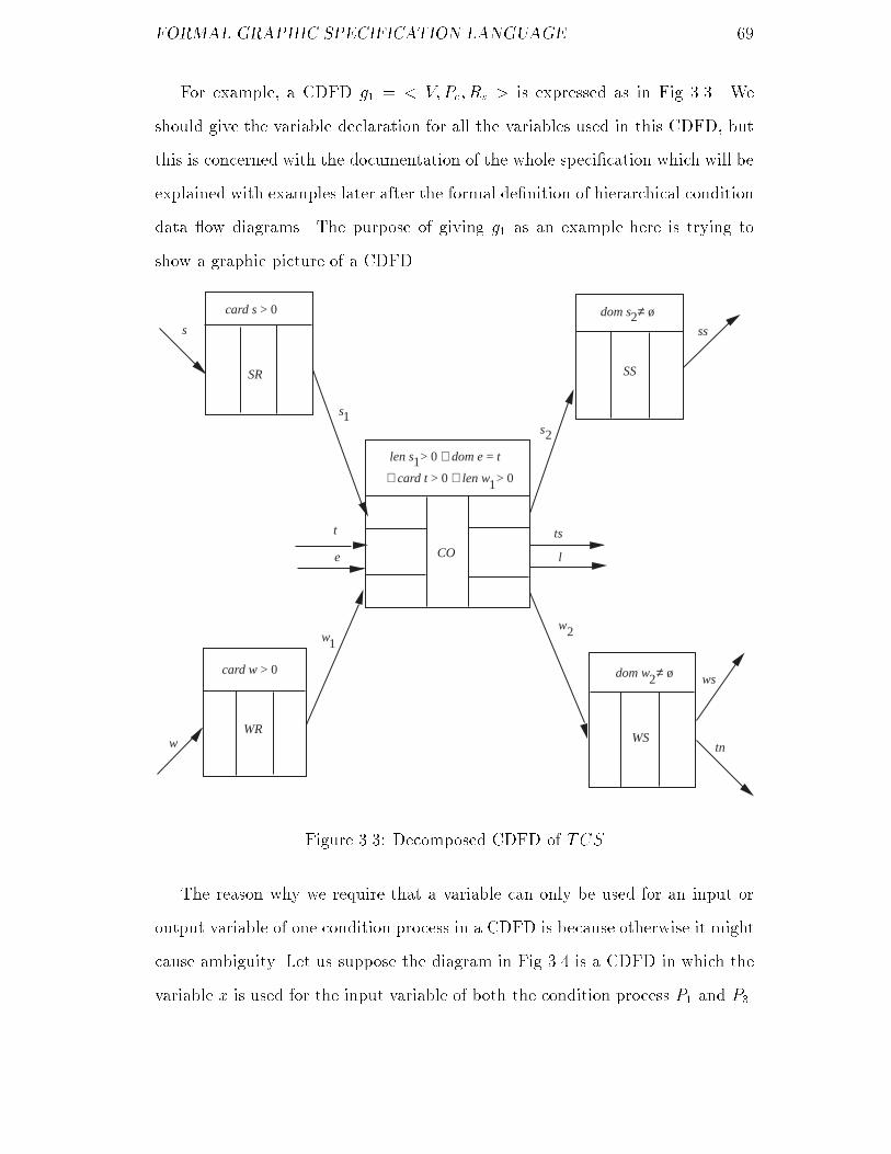
FORMAL GRAPHIC SPECIFICATION LANGUAGE ��
For example a CDFD g� � � V�Pc� Rs � is expressed as in Fig ���� We
should give the variable declaration for all the variables used in this CDFD but
this is concerned with the documentation of the whole speci�cation which will be
explained with examples later after the formal de�nition of hierarchical condition
data �ow diagrams� The purpose of giving g� as an example here is trying to
show a graphic picture of a CDFD�
s
SR
card s > 0
WR
card w > 0
t
e CO
ts
l
WStn
ws
SS
ss
s1
len s > 0 ∨ dom e = t1
s2
dom s ≠ ø2
ww
12
w
∧ card t > 0 ∨ len w > 01
dom w ≠ ø2
Figure ���� Decomposed CDFD of TCS
The reason why we require that a variable can only be used for an input or
output variable of one condition process in a CDFD is because otherwise it might
cause ambiguity� Let us suppose the diagram in Fig ��� is a CDFD in which the
variable x is used for the input variable of both the condition process P� and P��

FORMAL GRAPHIC SPECIFICATION LANGUAGE �
We cannot distinguish the x as the input variable of P� from the x as the input
variable of P�� Therefore we have to treat them as the same variable and used for
representing the same data available through them every time� However when
P� is �red due to data through the variable y being available data through x is
produced as the output of P�� At the same time we also have to think that data
through the x which is the input variable of P� is available� Consequently This
will cause in�nite loop and produce in�nite output through P�� As every CDFD
in a hierarchical condition data �ow diagram corresponds to its parent condition
process which will be described later and every condition process only produce
output data once when it is �red such a diagram in Fig ��� cannot have any
parent condition process which contradicts our design rational of hierarchical
condition data �ow diagram�
x y x z
1 2 3P P P
Pre(P ) Pre(P ) Pre(P )1 2 3
Figure ���� Example of an incorrect CDFD
����� Decomposition of Condition Processes
As industry scale software systems are usually very large and complicated to
express the functionality of an upper level condition process of a system by
directly giving its post�condition is extremely di�cult �if possible�� Even the
post�condition could be expressed by the formal notation provided by VDM
its readability would be very poor� Therefore the FGSL is designed to be a
structured analysis method� The analysis of problems is carried out hierarch�
ically through the decomposition of condition processes� The purpose of doing
this decomposition is to spell out the details of a condition process� The result

FORMAL GRAPHIC SPECIFICATION LANGUAGE �
of this decomposition is another condition data �ow diagram� Consequently a
hierarchical condition data �ow diagram is established�
De�nition �� �hierarchical condition data ow diagram� A hierarchical
condition data �ow diagram is a four tuple� �Vd� Q� G� f� where Vd is a set of
typed variables Q is a set of condition processes whose input and output variables
are from Vd G is a set of condition data �ow diagrams and f which is called
decomposition function is a partial function from Q to G� In addition it satis�es
the conditions�
�� Let Q � fP�� P�� ���� Pmg� Then
Vd � S�Input�P��� � S�Input�P��� � ��� � S�Input�Pm��
�S�Output�P��� � S�Output�P��� � ��� � S�Output�Pm���
�� Let G � f� V �� P �c � R
�s �� � V �� P �
c � R�s �� ���� � V n� P n
c � Rns �g� Then
Q � P �c � P
�c � ��� � P n
C �
In the hierarchical condition data �ow diagram �Vd� Q� G� f� The collection of
all the variables used for input and output variables of all the condition processes
in Q is Vd� The collection of all the condition processes used in all the condition
data �ow diagrams in G is Q� The decomposition function f expresses which
condition processes are decomposed into which CDFDs�
Condition processes which are the members of the domain of the decompos�
ition function f will be called non�terminal condition processes and other con�
dition processes in Q terminal condition processes� The non�terminal condition
processes are similar to the upper level condition processes metioned before and
the terminal condition processes are similar to the bottom level condition pro�
cesses� However the terminology non�terminal �or terminal� condition processes
is better than upper level �or bottom level� condition processes in the sense that

FORMAL GRAPHIC SPECIFICATION LANGUAGE �
it emphasizes the state of condition processes in the process of the decompos�
ition and possesses the precise de�nition� Therefore we use the terminology
non�terminal and terminal condition processes instead of upper level and bottom
level condition processes from now on�
For the non�terminal condition process P if f�P � � g where g � G then the
CDFD g is called the decomposed CDFD of P all the condition processes in g
are called child condition processes of P and P is called their parent condition
process� The formal relationship between a non�terminal condition process and
its decomposed CDFD will be addressed later�
In a FGSL speci�cation the hierarchical condition data �ow diagram is ex�
pressed separately in a sequence of condition process de�nitions� As metioned
in section ��� each condition process in the hierarchical condition data �ow dia�
gram possesses a de�nition� The decomposed CDFD of a non�terminal condition
process is included in its de�nition for describing its functionality� For a terminal
condition process its functionality is described by pre� and post�conditions which
will be discussed later�
For example we extend the speci�cation of the Training Centre System given
in section ����� by decomposing TCS into the CDFD in Fig ��� and further de�
composing CO in this CDFD into the CDFD in Fig ���� The additional de�nitions
of TCS and CO are as follows in turn�
TCS �TOP
TYPE
StudyInf � map PersonalInf to N
VAR
s� w� � seq of PersonalInf
s� w� � StudyInf
FUN

FORMAL GRAPHIC SPECIFICATION LANGUAGE �
The decomposed CDFD of TCS is as shown in Fig ����
COM
The SR WR CO SS and WS stand for Student Registration Worker Re�
gistration Courses Organization Sorted Students and Worker Selection respect�
ively�
END�TCS
CO �TCS
VAR
t�� t�� t�� � seq of PersonalInf
tc� tc� tc� � StudyInf
FUN
The decomposed CDFD of CO is as shown in Fig ����
COM
The SC and WC stand for Student Courses and Worker Courses respectively�
The TR PC MC BC and TS stand for Teacher Registration Ph�D Courses
M�Sc Courses B�Sc Courses and Teacher Selection respectively�
END�CO
where we use the assumed condition process TOP as the parent condition process
of TCS as it does not have its real parent condition process� The parent condition
process of CO is TCS�
If we name the CDFD in Fig ��� g� the CDFD in Fig ��� g� and the CDFD
in Fig ��� g� the decomposition function of the hierarchical condition data �ow
diagram expressed in the speci�cation of the Training Centre System is as follows�
f � f� TCS� g� �� � CO� g� �g
There are two problems open now� One is how to de�ne terminal condition
processes� The other is how CDFDs in a hierarchical condition data �ow diagram
share the declared types and variables� As the new problem of sharing the de�ned

FORMAL GRAPHIC SPECIFICATION LANGUAGE �
t
eTR
dom e = t ∧ card t > 0
TS
ts
l
SC
true
true
true
PC
MC
BC
WC
s1 s2
len s > 01
t11
t
t
12
13
tc
tc
tc
1
2
3
dom tc ≠ ø ∨ dom tc ≠ ø
∨ dom tc ≠ ø1 2
3
ww
1 2
len w > 01
Figure ���� Decomposed CDFD of CO

FORMAL GRAPHIC SPECIFICATION LANGUAGE �
functions for expressing the functionality of terminal condition processes occurs
when we discuss terminal condition process de�nitions the issue of the scopes
of declared types variables functions and condition processes will be addressed
together after the discussion of terminal condition process de�nitions and the
explanation of condition process properties in this section�
����� De�nition of Terminal Condition Processes
The de�nition of a terminal condition process possesses the same syntactic struc�
ture as that of a non�terminal condition process but the functionality is described
by the pre� and post�conditions� The relationship between input and output vari�
ables are usually given explicitly in the post�condition� The abstract syntax of
the Functionality in a terminal condition process de�nition is as follows�
PRE� pre�P
POST � post�P
�FUNCTION�
�Function Declaration�
where PRE and POST are key words to indicate that the pre�condition and the
post�condition are followed respectively� The pre�P denotes the content of the
pre�condition and the post�P denotes the content of the post�condition� The
FUNCTION is a key word to indicate that the function declaration is followed�
The Function Declaration is a sequence of function declarations which are for
de�ning functions used in the pre�P or post�P � Each function declaration gives
the signature and the de�nition body� The de�nition body can be expressed
explicitly or implicitly using the corresponding mechanism available in VDM�
This part is optional for a terminal condition process de�nition�
In order to keep pre�conditions �of terminal and non�terminal condition pro�
cesses� as simple as possible for facilitating the description of post�conditions of

FORMAL GRAPHIC SPECIFICATION LANGUAGE �
other related condition processes in a CDFD the pre�P can only use conditions
with the syntax de�ned in de�nition ���� The post�P may use any kind of condi�
tions allowed in VDM but the di�erence from the post�condition of an operation
in VDM in general is that there is no external variables in post�P � It only includes
input and output variables�
For example we can now extend the speci�cation of the Training Centre
System described before by given the de�nitions of all the terminal condition
processes occurring in Fig ��� Fig ��� and Fig ���� These de�nitions are as
follows in turn�
SR �TCS
FUN
PRE� card s � �
POST � elem s� � s � len s� � card s
COM
This condition process transforms a set of students into a sequence of regis�
trated students according to their registration order�
END�SR
SC �CO
FUN
PRE� len s� � �
POST � EXAM�s� s��
FUNCTION
EXAM � seq of PersonalInf � StudyInf �� B
EXAM�l� m� � domm � elem l� � x�elem l��r�N � �r � � � r �
��� �m�x� � r�
COM
This condition process transforms a sequence of registrated students into a

FORMAL GRAPHIC SPECIFICATION LANGUAGE
collection of students with their study records�
END�SC
SS �TCS
FUN
PRE� dom s� �� �
POST � dom s� � elem ss � card dom s� � len ss �
IS�SORTED�ss� s��
FUNCTION
IS�SORTED � FinalSequence� StudyInf �� B
IS�SORTED�l��m� � i�j�inds l��x�y�elem l� � l��i� � x � l��j� �
y � i � j �� m�x� � m�y�
COM
This condition process transforms a set of students with their study records
into a sorted sequence of students with their records� These students are sorted
in descending order according to their study records�
END�SS
WR �TCS
FUN
PRE� card w � �
POST � elemw� � w � len w� � card w
COM
This condition process transforms a set of workers into a sequence of regis�
trated workers according to their registration order�
END�WR
WC �CO
FUN
PRE� len w� � �

FORMAL GRAPHIC SPECIFICATION LANGUAGE
POST � EXAM�w�� w��
COM
This condition process transforms a sequence of registrated workers into a
collection of workers with their study records�
END�WC
WS �TCS
FUN
PRE� dom w� �� �
POST � dom w� � elemws � card dom w� � len ws �
IS�SORTED�ws�w�� � tn � fx j x � dom�w�� � w��x� �
�g
COM
This condition process transforms a set of workers with their study records
into a sequence of workers which is sorted in descending order according to their
study records and a set of technicians who are selected from the input set of
workers according to a criterion�
END�WS
TR �CO
FUN
PRE� dom e � t � card t � �
POST � elem t�� � fx j x � t � e�x� � Ph�Dg
� elem t�� � fx j x � t � e�x� � M�Scg
� elem t�� � fx j x � t � e�x� � B�Scg
� len t�� � len t�� � len t�� � card t
COM
This condition process transforms a set of teachers with di�erent degrees into
three sequences of teachers according to their registration order� Each sequence
corresponds to a subset of teachers which constitute this sequence� The three sets

FORMAL GRAPHIC SPECIFICATION LANGUAGE �
of teachers corresponding to these three sequences of teachers is a partition of the
input set of teachers� One of them includes all the teachers with Ph�D degree�
Another includes all the teachers with M�Sc degree and the rest one includes all
the teachers with B�Sc degree�
END�TR
PC �CO
FUN
PRE� true
POST � if len t�� � � then EXAM�t��� tc�� else dom tc� � �
COM
This condition process transforms a sequence of teachers with Ph�D degree
into a set of teachers with their study records�
END�PC
MC �CO
FUN
PRE� true
POST � if len t�� � � then EXAM�t��� tc�� else dom tc� � �
COM
This condition process transforms a sequence of teachers with M�Sc degree
into a set of teachers with their study records�
END�MC
BC �CO
FUN
PRE� true
POST � if len t�� � � then EXAM�t��� tc�� else dom tc� � �
COM
This condition process transforms a sequence of teachers with B�Sc degree

FORMAL GRAPHIC SPECIFICATION LANGUAGE �
into a set of teachers with their study records�
END�BC
TS �CO
FUN
PRE� dom tc� �� � dom tc� �� � dom tc� �� �
POST � let tc� y tc� y tc� � a in dom a � elem ts �
IS�SORTED�ts� a� � l � fx j x � dom a � a�x� � ��g
COM
This condition process transforms three sets of teachers with their study re�
cords into a sequence of teachers which is sorted in descending order according
to their study records and a set of lecturers who are selected from the three input
sets of teachers according to a criterion�
END�TS
����� Explanation of Properties of Condition Processes
Now we have got enough concepts to explain why the properties given in section
����� must be satis�ed by every condition process in the hierarchical condition
data �ow diagram of a FGSL speci�cation�
Property � �rst requires that the input data expression is always in dis�
junctive normal form and each input variable is used in exactly one data con�
junction of its input data expression� This is because �rst it is di�cult �if pos�
sible� in general to express the input data expression graphically if it is not in
disjunctive normal form� For instance let Input�P � of condition process P be
x� � �x� � �x� � �x� � x����� The di�culty of expressing it graphically in the
associated condition data �ow diagram can be imagined�
Second if the input expression of P is not in disjunctive normal form when
P is decomposed into a CDFD it might cause violation of the condition which a

FORMAL GRAPHIC SPECIFICATION LANGUAGE �
CDFD must satis�es � For example let Input�P � � x��y�z� and Output�P � � l�
We cannot give the graphic representation of such a condition process using the
de�ned graphic notation as its input data expression is not in disjunctive normal
form� Suppose P is decomposed into the condition data �ow diagram in Fig ����
According to de�nition �� this CDFD violates the �rst required condition as
S�Input�P��� � S�Input�P��� �� ��
x
y
x
z
t
q
l
P
P
P
1
2
3
Pre(P )
Pre(P )
Pre(P )
1
2
3
Figure ���� Example of an incorrect Decomposed CDFD
However this constraint in input data expressions of condition processes does
not prevent us from expressing such an expected condition process whose input
data expression is x � �y � z� �sometimes it is really needed for modelling a
physical system in the real world�� It can be represented by such a CDFD �or
part of a CDFD� in Fig �� instead of one condition process�
The second requirement of Property � is for preventing the following case
for example in the pre�condition of P �
Input�P � � x� � x� � y� � y�
Pre�P � � x� � � � y� � �� x� � � � y�

FORMAL GRAPHIC SPECIFICATION LANGUAGE �
y
z
t
xl
P
P
Pre(P )
Pre(P )
1
2
1
2
Figure ��� Example of a CDFD
where x� x� y� and y� are assumed to be real number variables�
To satisfy this pre�condition either both x� and y� or both x� and y� is
required� However the Input�P � requires either both x� and x� or both y� and y�
for �ring P � Therefore whenever input data are available for P its pre�condition
is not satis�ed� This contradicts our design rational of condition processes�
Furthermore as for any condition process P the Input�P � � X� � X� �
��� �Xn and PD�S�X��� S�X��� ���� S�Xn�� and the pre�condition is a disjunction
Pre�P � � C�C� ��� Cn such that i�����n���j�����n� �S�Xi� � DS�Cj� according
to the Property � it seems that the disjunction operator in the pre�condition
should be replaced by the exclusive disjunction operator �� In fact this will
cause contradiction with our design rational of condition processes that whenever
their input data are available their pre�conditions should be satis�ed by the
input data� Let us study the non�terminal condition process P� which may be a
top level condition process of a hierarchical condition data �ow diagram where
Input�P�� � x� y � z � q and Pre�P�� � �x � � � y � �� �z � � q � ��� If
we change this pre�condition into Pre�P�� � �x � �� y � �� � �z � � q � �� it

FORMAL GRAPHIC SPECIFICATION LANGUAGE �
will cause trouble sometimes� Let us assume that data through the variables x
y and z are available then it will cause �ring of P�� At the same time we want
the Pre�P�� to be true but this is not true in this case as both �x � � � y � ��
and z � � might be true and eventually make the Pre�P�� false due to �� Note
that as long as z � � is true no matter whether q � � is true false or non�value
the z � � q � � is true according to the extended logic system which will be
introduced in section ����
There are two reasons for Property � which requires that the input variables
output variables and the name of a condition process are all distinct� First we
want to emphasize the concept of data �ow through a condition process� If the
same variable is allowable for being both input and output variable of the same
condition process the concept of state change through this condition process
must be used� Furthermore it can also prevent the case expressed in Fig ��
which is not sensible in semantics as the condition process P can never be �red�
y
x
zP
Figure ��� An example of incorrect CDFD
Second distinguishing the name of a condition process from its input and
output variables is for preventing ambiguity in understanding speci�cations�

FORMAL GRAPHIC SPECIFICATION LANGUAGE �
We do not need to explain Property � in detail as this explanation is similar
to that of Property �� But one more thing to emphasize is that Property �
does not prevent the case expressed in Fig ��� in which there are two directed
lines with the same label y �which is an output variable of the condition process
P � from P to the condition processes P� and P�� This mechanism can be used to
facilitate the representation of a special situation�
x
y
y
z
l
q
P
P
P
Pre(P )
Pre(P )
1
2
1
2
Pre(P)
Figure ���� An example of CDFD
For example suppose a sub�system of the fault tree support system interface
�McDermid ��b� is required� Let p� denote the �rst picture of interface produced
by �ring of the condition process IP �Interface Production� which includes a
drawn fault tree� Through the condition process SC �Syntax Checking� the
result information about the syntax of the fault tree which is denoted by si and
the original picture p� as well as the probability information of the fault tree pi
are expected to be provided for users and the input for the following condition
process CC �Consistency Checking� respectively� A natural way of representing
this situation is as shown in Fig ���� where p� � p�� But using the mechanism
metioned above a more explicit way of expressing this situation is as shown in

FORMAL GRAPHIC SPECIFICATION LANGUAGE �
Fig �����
com
P
p
pCC
1
i
2
s
p
i
3
IP
SC
Pre(IP)
Pre(SC)
Pre(CC)
Figure ����� Correct but implicit CDFD
com
p
p
s
p
pIP
SC
CC
i
i
1
31
Pre(IP)
Pre(SC)
Pre(CC)
Figure ����� More explicit CDFD
Let us take the condition process P� in the CDFD in Fig ���� as the example to
explain Property �� This property guarantees that only is when data through
one of x� and x� �not both� is available P� is �red and one of y and z �not
both� is produced once �not many times� after �ring P�� Otherwise it will cause
ambiguity in semantics� Suppose data through both y and z are produced after
�ring P� the P� and P� are then �red and data through l and q are produced
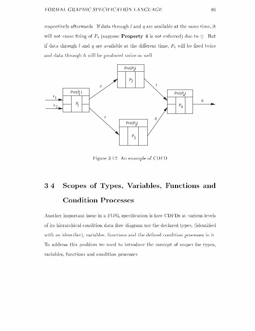
FORMAL GRAPHIC SPECIFICATION LANGUAGE �
respectively afterwards� If data through l and q are available at the same time it
will not cause �ring of P� �suppose Property � is not enforced� due to �� But
if data through l and q are available at the di�erent time P� will be �red twice
and data through h will be produced twice as well�
x1
x 2
y
z
l
q
hP1
P
P
P
2
3
4
Pre(P ) Pre(P )
Pre(P )
Pre(P )
1
2
3
4
Figure ����� An example of CDFD
��� Scopes of Types� Variables� Functions and
Condition Processes
Another important issue in a FGSL speci�cation is how CDFDs at various levels
of its hierarchical condition data �ow diagram use the declared types �identi�ed
with an identi�er� variables functions and the de�ned condition processes in it�
To address this problem we need to introduce the concept of scopes for types
variables functions and condition processes�

FORMAL GRAPHIC SPECIFICATION LANGUAGE
����� Scopes of Types and Variables
As the input and output variables of a non�terminal condition process have to be
used by its some child condition processes in its decomposed CDFD �this point
will be clear later when discussing the formal semantics of hierarchical condition
data �ow diagrams� it is necessary for all the types and variables declared in the
de�nition of the non�terminal condition process to be inherited in the de�nitions
of all its child condition processes in order not to declare same types and variables
many times at di�erent levels in a FGSL speci�cation� For this reason we can
formally de�ne the using scope of types and variables� To do this we �rst need to
introduce the notions descendant ancestor and brother of a condition process�
De�nition ��� �descendant� ancestor� Let �Vd� Q� G� f� be a hierarchical
condition data �ow diagram� If there exist the condition processes P� P� ��� Pn
in Q such that Pi is the parent condition process of Pj for i � j�� and � � j � n
then the Pn is called a descendant of P� and P� is called an ancestor of Pn�
De�nition ���� �brother� If there exist the condition processes P� P� P� � Q
in the hierarchical condition data �ow diagram �Vd� Q� G� f� such that P� is the
parent condition process of P� and P� then P� and P� are called brothers�
De�nition ���� �scope� Let �Vd� Q� G� f� be the hierarchical condition data
�ow diagram of the FGSL speci�cation Sf P � Q and D be the set of all
descendants of P � Then the scope of the types and variables declared in the
de�nition of P is the set of the de�nitions of all its descendants in Sf �
That is when a condition process is de�ned in a FGSL speci�cation all the
types and variables declared in the de�nitions of its ancestors can be directly
used �without declaring them� if necessary� This rule prohibits a condition process
de�nition from declaring the same types or variables as its ancestors but allow its
brothers and their descendants to declare the same types or variables di�erently
for their local use�

FORMAL GRAPHIC SPECIFICATION LANGUAGE
For example the types and variables declared in the de�nition of the condition
process TCS in the speci�cation of the Training Centre System given in previous
section are directly used in the de�nitions of its descendants SR WR CO SS
WS TR and TS�
����� Scopes of Functions
As all the functions to be used in pre� or post�conditions of condition processes
in a FGSL speci�cation are declared only in the de�nitions of terminal condition
processes each of them should be declared uniquely �in terms of its name� for
keeping the speci�cation as simple as possible� Therefore we specify that the
scope of a function declared in the de�nition of a terminal condition process is
the set of the de�nitions of all the condition processes in the hierarchical condition
data �ow diagram of the FGSL speci�cation�
For instance the functions EXAM and IS�SORTED declared respectively
in the de�nitions of the terminal condition processes SC and SS of the Training
Centre System are used in the de�nitions of the terminal condition processes WC
PC MC BC WS and TS respectively�
����� Scopes of Condition Processes
As a condition process is usually used for modelling an object in the real world
such as a university a department or a class of students etc �but not limited to
this kind of application� when problems in the real world are analysed by using
FGSL and the name of the condition process is its unique identi�er we restrain a
condition process from being used twice within a hierarchical condition data �ow
diagram� That is the scope of using a condition process is only the de�nition of
its parent condition process �actually within the decomposed CDFD of its parent
condition process��

FORMAL GRAPHIC SPECIFICATION LANGUAGE �
��� Logic in FGSL
Throughout the discussion on FGSL before we have avoided the issue of logic
used in FGSL on purpose as we did not meet any troubles without clari�ng this
matter� However it will be necessary to do this if the formal semantics of FGSL
speci�cations is intended to be addressed� In fact FGSL uses the same logic
system as VDM but there are more reasons to do so�
Meaning extension of logical operators
We start the study of this issue by examining a simple example below�
Let P be a condition process and its components be�
Pre�P � � x� � � x� � �
Input�P � � x� � x�
Output�P � � y� � y�
where x� and x� are two natural numbers�
When the firing of the condition process P occurs one of the variables x�
and x� must have been bound to data and the other is unde�ned according to
Property � of a condition process� In this case if the logical operator is the
disjunction operator of classical logic �two�value� the condition x� � � x� � �
will fail to denote a truth value�
Therefore a logical system which handles this problem should be provided�
The problem to be addressed is what meaning is to be given to the logical op�
erators if the atomic proposition �ex x� � � or x� � �� fails to denote a truth
value� The approach adopted in FGSL is to extend the meaning of the logical
operators in the exactly same way as in VDM �Jones ��� The new truth tables
of the logical operators are given in Appendix B in which the symbol � is used
to denote a �non�value�� But there is no sense in which � is a new value � it is
just a reminder that no value is available�

FORMAL GRAPHIC SPECIFICATION LANGUAGE ��
Syntax and meaning extension of the symbol true
In VDM when the symbol true is used for a pre�condition of an operation it
means the pre�condition can be any condition �hence its value is always true no
matter what the input values are�� However if the same symbol is employed
directly in FGSL to represent the pre�condition of a condition process a problem
will arise�
Let us study the condition process P��
Pre�P�� � x� � � true
Input�P�� � x� � x�
Output�P�� � y� � y�
When data through x� is available the firing of this condition process occurs
and the condition x� � � true is wanted to get a truth value only depending on
x� � �� However x� � � true always gets a true value due to the symbol true�
Therefore the symbol true has to be modi�ed to cope with this case in FGSL�
We need to extend the expression form and the meaning of the symbol true� The
approach of the extension is explained as follows�
Let the input data expression of the condition process P be�
Input�P � � X� �X� � ����Xn
and the pre�condition of P is�
Pre�P � � C� C� ��� Cn�
If we want the Ci �i�����n� which corresponds to Xi in Input�P � always to be
true the Ci is expressed as true�xi�� xi�� ���� xim� where S�Xi� � fxi�� xi�� ���� ximg�
Its meaning is� if Xi is available then true�xi�� xi�� ���� xim� � true� Otherwise it
denotes a �non�value� ��
Similarly for an input variable xij for j � ����m true�xij� � true if data
through xij is available� Otherwise it also denotes a �non�value��
We can therefore derive the following from the above extensions�

FORMAL GRAPHIC SPECIFICATION LANGUAGE ��
true�xi�� xi�� ���� xim� �� true�xi�� � true�xi�� � ��� � true�xim�
This relation will be applied implicitly in the discussion of condition consistency
in next chapter�
According to the above discussion the pre�condition of the condition process
P should be expressed in the FGSL speci�cation as�
Pre�P � � x� � � true�x��
However for the sake of convenience the symbol true is still available to be
used if necessary to represent the pre�condition of a condition process if its
input data expression is a data conjunction� That is for example if the input
data expression of the condition process P is� Input�P � � x� � x� � ��� � xn
where each xi �i � ����n� is a variable then true�x�� x�� ���� xn� is represented by
the symbol true� This expression indeed facilitates the description without any
confusion in semantics�
Note that all the extensions introduced above are also applicable to the post�
conditions of condition processes�
��� Formal Semantics of Hierarchical Condition
Data Flow Diagrams
As the heart of a FGSL speci�cation is a hierarchical condition data �ow diagram
as long as the semantics of the hierarchical condition data �ow diagram is de�ned
precisely the semantics of the FGSL speci�cation becomes clear� The description
of hierarchical condition data �ow diagrams in previous setions focused on their
syntax and some informal explanations of their semantics� However it will be
necessary to provide the formal semantics for hierarchical condition data �ow
diagrams if consistency within them needs de�ning and checking� It will also be
necessary to supply a �rm foundation to system implementation and veri�cation�

FORMAL GRAPHIC SPECIFICATION LANGUAGE ��
It is preferable to choose the approach of axiomatic semantics rather than
denotational semantics as the former can directly provide axioms and rules of
inference for checking consistency of a hierarchical condition data �ow diagram�
Since there are two mechanisms for specifying a condition process of a hier�
archical data �ow diagram which are data availability and pre� and post�conditions
the formal semantics has to be described in these two aspects respectively�
����� Availability Semantics
The availability semantics of a hierarchical condition data �ow diagram de�nes
its semantics from the data availability point of view� It is described by formally
de�ning the three relationships� relationship between input data and output data
of a condition process relationship between parent condition process and its
decomposed CDFD and relationship between all the connected sub�CDFDs of a
disconnected CDFD�
To de�ne this kind of semantics we �rst need to de�ne the notions� connec�
ted CDFD disconnected CDFD input condition processes of a CDFD output
condition processes of a CDFD and �ring of a CDFD as well as the necessary
notation�
De�nition ���� �connected and disconnected CDFD� Let g �� V�Pc� Rs �
be a condition data �ow diagram �CDFD�� If it can be divided into the two CD�
FDs g� �� V �� P �c � R
�s � and g� �� V �� P �
c � R�s � which satisfy the conditions�
� V � � V � � V � V � � V � � �
� P �c � P
�c � Pc � P �
c � P�c � �
� R�s �R
�s � Rs �R�
s �R�s � �
then g is called a disconnected CDFD and g� and g� are called sub�CDFDs of g�
Otherwise g is called a connected CDFD�

FORMAL GRAPHIC SPECIFICATION LANGUAGE ��
For instance the CDFD in Fig ��� is a connected CDFD while the CDFD in
Fig ��� is a disconnected CDFD which consists of three connected sub�CDFDs�
De�nition ���� �input� output� middle condition processes� Let g ��
V�Pc� Rs � be a CDFD P � Pc Input�P � � X��X�� ����Xn and Output�P � �
Y� � Y� � ��� � Ym� If
�i�����n�P��Pc � S�Xi� � S�Output�P��� � �
then P is called an input condition process of g� If
�j�����m�P��Pc � S�Yj� � S�Input�P��� � �
then P is called an output condition process of g� If P is neither an input
condition process nor an output condition process it is called a middle condition
process of g�
Informally a condition process is an input �or output� condition process of a
CDFD if none of all the input �or output� variables constituting a data conjunc�
tion of its input �or output� data expression is an output �or input� variable of
any condition process in this CDFD� Note that a condition process may be both
an input and output condition process of a CDFD�
For example the condition processes SR and WR in the CDFD in Fig ��� are
its two input condition processes and SS and WS are its two output condition
processes while CO is its middle condition process�
Based on the description of the action �ring of a condition process given in
section ����� �ring of a CDFD is de�ned as follows�
De�nition ���� ��ring of a CDFD� Let g �� V�Pc� Rs � be a CDFD� g is
�red if and only if there exists a set of condition processes in g which satis�es the
conditions�
� Every condition process in this set is �red�
� This set is divided into the three subsets of condition processes Ip Mp and
Op such that Ip is a non�empty set of input condition processes of g Mp

FORMAL GRAPHIC SPECIFICATION LANGUAGE ��
is a set �may be empty� of middle condition processes of g and Op is a
non�empty set of output condition processes of g�
Note that �ring of a CDFD de�nitely terminates since �ring of any condition
process of this CDFD terminates�
The notation to be used is described as follows�
� Firing�g� indicates that the CDFD g �might be one condition process� is
�red�
� AV L��E� for E being the data disjunctive normal form E��E�� ��� �En
represents the following meaning�
��i�����n�x�S�Ei� �AV L�x� � �j�����n� � j �� i �� y�S�Ej� � �AV L�y��
� fC�g g fC�g denotes that if the assertion C� is true and the CDFD g is
�red then the assertion C� is true after the �ring terminates� For the sake
of simplicity we call C� and C� the pre�assertion and post�assertion of g
respectively�
�
C�
C�
� � �
Cn
C
denotes the rule of inference which states that whenever C� C� ��� Cn are
true assertions then C is also a true assertion�
�
C�
C�
� � �
Cn
C

FORMAL GRAPHIC SPECIFICATION LANGUAGE ��
denotes the rule of inference which states that C� C� ��� Cn are true
assertions if and only if C is a true assertion�
Now we can describe the availability semantics of a hierarchical condition data
�ow diagram by giving the following axiom and rules of inference based on the
notions and notation de�ned above�
Let P be a condition process and S�Input�P �� � fx�� x�� ���� xng�
Axiom A��
fAV L�Input�P ��g P
fAV L��Output�P �� � ��AV L�x�� AV L�x�� ��� AV L�xn��g
This axiom indicates that if P has available input data and is �red then it
will has available output data bound to all the variables constituting exactly one
of the data conjunctions of its output data expression and its all input variables
become unde�ned after this �ring terminates�
Rule A��
AV L�Input�P ��
Firing�P �
This rule states that �ring of P occurs if it has available input data�
Actually Axiom A�� and Rule A�� de�ne the semantics of the action �ring
of a condition process� Based on them the semantics of the action �ring of a
CDFD can be described� As every CDFD in a hierarchical condition data �ow
diagram is the decomposed CDFD of a condition process its semantics must be
related to that of its parent condition process in order to guarantee this CDFD
to re�ect the details of its parent condition process�
Rule A�� Let g be the decomposed CDFD of P �

FORMAL GRAPHIC SPECIFICATION LANGUAGE ��
Firing�P �
Firing�g�
This rule expresses that �ring of the decomposed CDFD of P occurs if and
only if �ring of P occurs�
Rule A��
fAV L�Input�P ��g P fAV L�Output�P ��g
fAV L�Input�P ��g g fAV L�Output�P ��g
This rule states that if P has available input data and is �red and it has
available output data after this �ring terminates then �ring of its decomposed
CDFD g with the same available input data also produces the same available
output data as its parent does after this �ring terminates�
Rule A�� Let g consist of the disconnected CDFDs g� �� V �� P �c � R
�s �
g� �� V �� P �c � R
�s � ��� gn �� V n� P n
c � Rns � X� X� ��� Xn Y� Y� ��� Yn be
data expressions S�X���S�Y�� � V � S�X���S�Y�� � V � ��� S�Xn��S�Yn� �
V n�
fAV L�X��g g� fAV L�Y��g
fAV L�X��g g� fAV L�Y��g
���
fAV L�Xn�g gn fAV L�Yn�g
fAV L�X� �X� � ��� �Xn�g
g fAV L�Y� � Y� � ��� � Yn�g
This rule expresses that under the assumption of g being a disconnected CDFD
consisting of the connected CDFDs g� g� ��� gn if �ring of gi �i � ����n�� trans�
formes available Xi into available Yi then �ring of g will transformes available
X� �X� � ��� �Xn into available Y� � Y� � ��� � Yn and vice versa�

FORMAL GRAPHIC SPECIFICATION LANGUAGE �
Note that we cannot change the operator � in this rule to the operator �
as that could cause contradiction with the requirement of the rule A��� Let us
examine the condition process P whose input and output data expressions are
Input�P � � x � y � z and Output�P � � l � k� Firing of P occurs if and only
if data through all these three variables x y and z are available and a datum
through one of the variable l and k is produced� However if P is decomposed
into the CDFD in Fig ���� then only is when a datum through z is available the
condition process P� in this CDFD is �red and a datum through k is produced�
This contradict the rule A���
����� Functionality Semantics
The previous discussion on availability semantics of a hierarchical condition data
�ow diagram has revealed how its available input data �actually available data
of some input condition processes of its top level CDFD� is transformed into
its available output data� But it could not expresses what conditions should be
satis�ed by available input data and available output data� As the functionality of
a condition process �further a condition data �ow diagram� can only be speci�ed
precisely by giving its pre� and post�conditions based on its clear availability
semantics we intend to express the precise semantics of the condition process by
using its pre� and post�conditions�
The functionality semantics of a hierarchical condition data �ow diagram
de�nes its semantics from functionality point of view� It is described by giv�
ing the following axiom and rules of inference based on the notions and notation
de�ned previously� Before doing this we need the notation�
Dom�E� � T� � T� � ��� � Tn for the data expression E whose S�E� �
fz�� z�� ���� zng where Ti is the type of the variable zi for i � ����n�
Axiom F��

FORMAL GRAPHIC SPECIFICATION LANGUAGE �
x
y
z
l
k
P
P
1
2
Pre(P )
Pre(P )
1
2
Figure ����� A disconnected CDFD

FORMAL GRAPHIC SPECIFICATION LANGUAGE ��
Let P be a terminal condition process Pre�P � and Post�P � as described in
section ����� denote its pre�condition and post�condition respectively which are
given as part of its de�nition in the associated FGSL speci�cation� S�Input�P �� �
fx�� x�� ���� xng and S�Output�P �� � fy�� y�� ���� ymg� Then the axiom is expressed
as follows�
x��x������xq�Dom�Input�P �� � Pre�P ��x�� x�� ���� xq� ��
�y��y������yw�Dom�Output�P �� � Post�P ��x�� x�� ���� xq� y�� y�� ���� yw�
where � � q � n and � � w � m�
This axiom indicates that whenever the pre�condition of the condition process
P is satis�ed by a group of input data there must exist a group of output data
to satisfy the post�condition� This axiom is given based on the Axiom A�� and
Rule A�� described in previous section�
Rule F��
fPre�P �g P fPost�P �g
fPre�P �g P fPost�P � � Pre�P �g
As output variables in Post�P � are usually expressed in terms of input vari�
ables in Pre�P � the Pre�P � should be the background condition for Post�P � to
be true after the termination of the �ring of P �
Let P be any condition process and g is its decomposed CDFD�
Rule F��
AV L�Input�P ��
Pre�P �
This rule states that whenever input data of P is available its pre�condition
is satis�ed by the input data�
Rule F��

FORMAL GRAPHIC SPECIFICATION LANGUAGE ���
fC�g P fC�g
fC�g g fC�g
This rule expresses that the condition process P is equivalent to its decom�
posed CDFD in the sense that �ring of either of them under the assumption of
the same pre�assertion C� to be true will cause the same post�assertion C� to be
true after the �ring terminates�
Rule F��
Let g consist of the n disconnected CDFD g� g� ��� gn� Then
fC�prg g� fC
�pog
fC�prg g� fC
�pog
���
fCnprg gn fC
npog
fC�pr C
�pr ��� Cn
prg
g fC�po C
�po ��� Cn
pog
This rule corresponds to the Rule A��� It states that if C ipo �i � ����n�� is
true after the �ring of gi terminates under the assumption that C ipr is true when
the �ring occurs then C�po C�
po ��� Cnpo is true after the termination of the
�ring of g under the assumption that C�pr C
�pr ��� Cn
pr is true when the �ring
occurs�
The formal semantics of hierarchical condition data �ow diagrams described
in this section sets up the guidelines for structured speci�cation construction by
decomposing condition processes and the �rm foundation for consistency analysis
of the built speci�cations�

Chapter �
Model Consistency Analysis
When a FGSL speci�cation is constructed its hierarchical condition data �ow
diagram must obey the rules required by the syntax and semantics described in
the previous chapter� These rules can be divided into two groups� One group is
concerned with data availability and the other is concerned with functionality
of condition processes� The process of checking whether a speci�cation satis�es
these rules is called consistency analysis�
In this chapter we discuss the model consistency analysis� The purpose of
model consistency analysis is to guarantee the relevant rules concerned with data
availability are obeyed by a hierarchical condition data �ow diagram� Four aspects
of the model consistency need to be addressed� They are global consistency
structural consistency condition consistency and diagrammatical consistency�
The issues of global consistency and structural consistency of DeMarco data
�ow diagrams are discussed in �Tse �� but this discussion is limited to connected
�DeMarco� data �ow diagrams and the presentation lacks precision� The same
issues for a hierarchical condition data �ow diagram in a FGSL speci�cation
is also necessary to address but we take di�erent approach� The results may
be applied to both connected and disconnected condition data �ow diagrams�
After the discussion of global consistency and structural consistency the condition
���

MODEL CONSISTENCY ANALYSIS ���
consistency and diagrammatical consistency are described�
��� Global Consistency
When a hierarchical condition data �ow diagram is constructed through decom�
position of condition processes it must be guaranteed that the associated speci�c�
ation as a whole is de�ned as a hierarchical structure i�e� the decomposition is
not done recursively as illustrated in Fig ���� Otherwise some non�terminal con�
dition processes may remain unde�ned� According to the scope rule for condition
processes described in section ����� every condition process in the hierarchical
condition data �ow diagram must occur only once� If this property is maintained
every non�terminal condition process is guaranteed to be de�ned� We call this
property global consistency� Formally it is de�ned as follows�
De�nition ��� �global consistency� Let Hg � �Vd� Q� G� f� be a hierarchical
condition data �ow diagram g� �� V �� P �c � R
�s � and g� �� V �� P �
c � R�s � are
any two condition processes in G� Then Hg satis�es the global consistency if and
only if it satis�es the condition�
V � � V � � �
An algorithm for checking the global consistency of a hierarchical condi�
tion data �ow diagram can be simply derived from this de�nition� Let G �
fg�� g�� ���� gng n is a �nite natural number V �g� denote the set of all condi�
tion processes occurring in the CDFD g� Then this algorithm is summarized as
follows�
S �� f g�
FOR i �� � TO n DO
FOR j �� � TO n DO
BEGIN
IF V �gi� � V �gj� �� �
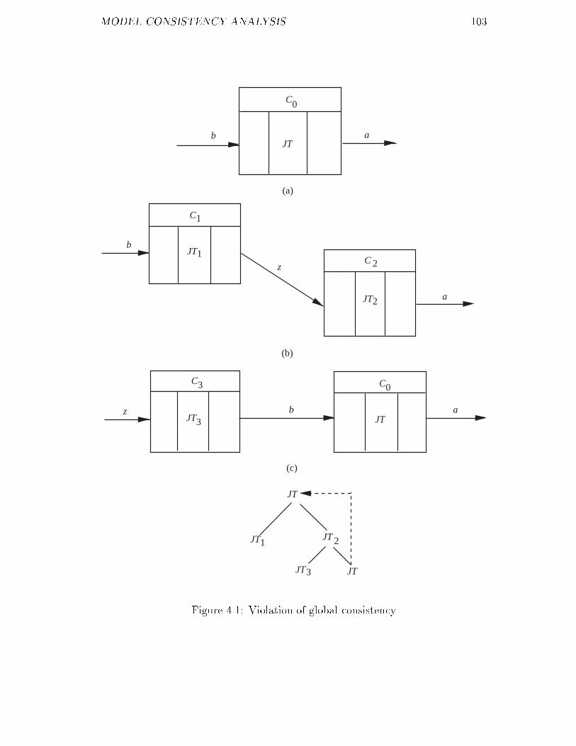
MODEL CONSISTENCY ANALYSIS ���
b a
(a)
b
z
a
z b a
(b)
(c)
JT
JT
C0
C
CJT
JT
C C
JT JT
JT
JT JT
1
21
2
3 0
3
1
3
JT 2
Figure ���� Violation of global consistency

MODEL CONSISTENCY ANALYSIS ���
THEN
S �� S � V �gi� � V �gj�
END�
This algorithm is expressed in Pascal�like language� The result of executing
this algorithm is to get the set denoted by S of all the condition processes which
occur more than once in the hierarchical condition data �ow diagram Hg� As this
algorithm is extremely simple the proof of it is omitted here�
For example the hierarchical condition data �ow diagram in the speci�cation
of the Training Centre System satis�es the global consistency�
��� Structural Consistency
Structural consistency is the balancing rule in structured analysis� any data �ow
entering �respectively leaving� a condition process P must also enter �respect�
ively leave� a condition process within the decomposed CDFD of P � This rule is
formally expressed by the Rule A�� in section ������
De�nition ��� �structural consistency� The decomposion of P into its de�
composed CDFD g will be structurally consistent if it obeys the Rule A���
A necessary and su�cient condition for structural consistency can now be
stated� The description of this condition needs two basic concepts� external input
data expression and external output data expression of a CDFD� The external
input data expression of CDFD g denoted by ext�inp�g� is a data expression
which consists of all external input variables in g� An external input variable is
an input variable to some condition process but not an output variable to any
condition process in g� The external output data expression of g denoted by
ext�outp�g� is a data expression which consists of all external output variables in
g� An external output variable is an output variable to some condition process

MODEL CONSISTENCY ANALYSIS ���
but not an input variable to any condition process in g� Furthermore we use ext�
inpset�g� and ext�outpset�g� to represent the sets of all external input variables
and all external output variables of g respectively�
�Theorem ���� Let �Vd� Q� G� f� be a hierarchical condition data �ow dia�
gram P � Q g � G be a connected CDFD and f�P � � g� The decomposion of
P into its decomposed CDFD g will be structurally consistent if and only if
� ext�inp�g� � Input�P � and
� ext�outp�g� � Output�P ��
where ext�inp�g� and ext�outp�g� are produced by algorithm ����
Proof� the aim of this proof is to prove two things� The �rst one is to prove
whether the Rule A�� is true can guarantee the conditions given in this theorem
to be satis�ed�
The second one is to prove that if the conditions given in this theorem is true
whether it can guarantee the Rule A�� to be satis�ed�
��� We will take the approach of proof by contradiction to prove the �rst
one� Suppose the Rule A�� is true� If ext�inp�g� � Input�P � �the discussion
for ext�outp�g� � Output�P � is similar� is not true then there must exist a data
conjunction in Input�P � say x��x�� ��� �xn such that there does not exist an
equivalent data conjunction in ext�inp�g� in the sense of their availability being
same�
From algorithm ��� we can know that each expression like
�L� � L�� ��� �Lk� �� �R� �R�� ��� �Rk��
produced through step � to of this algorithm represents that there is a path
�a sequence of condition processes� starting from some input condition processes
and ending at some output condition processes and the data conjunction on the
left side of this expression will cause �rings of all the condition processes on this

MODEL CONSISTENCY ANALYSIS ���
path in turn �consequently cause �ring of g according to the de�nition ���� in
section ������ if it is available �namely AV L�L� � L� � ��� � Lk� is true�� The
result of these �rings will make the data conjunction on the right side of this
expression available �namely AV L�R� � R� � ��� � Rk� is true�� According to
step in algorithm ��� this left side data conjunction must be one of all the data
conjunctions in the ext�inp�g� that if available can causes �ring of g� As g is a
connected CDFD all the data conjunctions in the ext�inp�g� are all the possible
data conjunctions which can cause �ring of g if they are available�
Therefore when the data conjunction x� � x� � ��� � xn is available which
consequently cause �ring of P it cannot cause �ring of g as otherwise there must
exist its equivalent data conjunction in ext�inp�g�� However this conclusion
contradicts the assumption that Rule A�� is true� Therefore there must be
ext�inp�g� � Input�P � �proof for ext�outp�g� � Output�P � is similar��
��� Suppose ext�inp�g� � Input�P �� According to algorithm ��� whenever
AV L�ext�inp�g�� is true g will be �red and cause AV L�ext�outp�g�� to be true�
Since ext�inp�g� � Input�P � �and ext�outp�g� � Output�P �� according to Rule
A�� given in section ����� whenever AV L�ext�inp�g�� is true P is �red and
Output�P � is caused to be true� Therefore Rule A�� is true�
�
In the algorithm ��� the operators � and � are not only applied to data
expressions but also extended to apply to any expressions for meeting the need
of expressing the algorithm� This extention preserves the properties of � and �
�e�g� commutativity��
Algorithm ����
�� Let P� P� ��� Pn be the condition processes of g� Relate each Pi with a
data transformation of form�
L�Pi� �� R�Pi�

MODEL CONSISTENCY ANALYSIS ��
where L�Pi� � Input�Pi� R�Pi� � Output�Pi�� Hence we represent g by a
combined transformation�
L� �� R� � L� �� R� � ���� Ln �� Rn�
�� For every transformation of the form �L� �L�� ��� �Lk� �� R expand it
to become�
L� �� R� L� �� R � ���� Lk �� R
�� For every transformation of the form�
L �� �R� �R� � ����Rl�
expand it to become
L �� R� � L �� R� � ���� L �� Rl
�� For every transformation of the form
L �� �R� �R�� ��� �Rt�
expand it to become
L �� R� � L �� R�� ��� �L �� Rt
�� Using the distributive property of the operator ��� over the operator ���
expand the expressions of transformations� For example
L� �� R� � �L� �� R� � L� �� R��
becomes
L� �� R� � L� �� R� � L� �� R� � L� �� R�
�� We de�ne a path as a combination of transformations joined together only
by ���s but not ���s� Do the following for each path�
����� For any L� �� R� such that R� is a subexpression of L for some
L �� R in the same path�
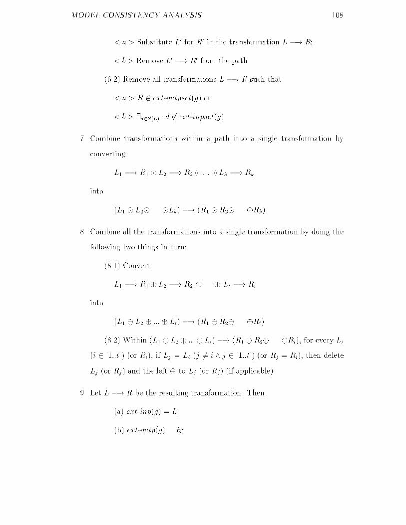
MODEL CONSISTENCY ANALYSIS ��
� a � Substitute L� for R� in the transformation L �� R�
� b � Remove L� �� R� from the path�
����� Remove all transformations L �� R such that
� a � R �� ext�outpset�g� or
� b � �d�S�L� � d �� ext�inpset�g��
� Combine transformations within a path into a single transformation by
converting
L� �� R� � L� �� R� � ���� Lk �� Rk
into
�L� � L�� ��� �Lk� �� �R� �R�� ��� �Rk��
� Combine all the transformations into a single transformation by doing the
following two things in turn�
���� Convert
L� �� R� � L� �� R� � ��� � Lt �� Rt
into
�L� � L� � ���� Lt� �� �R� �R�� ��� �Rt��
���� Within �L� � L� � ���� Lt� �� �R� �R�� ��� �Rt� for every Li
�i � ����t�� �or Ri� if Lj � Li �j �� i � j � ����t�� �or Rj � Ri� then delete
Lj �or Rj� and the left � to Lj �or Rj� �if applicable��
�� Let L �� R be the resulting transformation� Then
�a� ext�inp�g� � L�
�b� ext�outp�g� � R�

MODEL CONSISTENCY ANALYSIS ���
For example to see whether the decomposition of the condition process TCS
in Fig ��� into its decomposed CDFD g� in Fig ��� is structurally consistent we
need to use the algorithm ��� to obtain ext�inp�g�� and ext�outp�g�� through the
corresponding steps in the algorithm�
�� s �� s� � w �� w�
��s� � t� e� w� �� s� � ts� l� w��
�s� �� ss� w� �� ws � tn
�� s �� s� � w �� w�
���s� �� s� � ts� l � w��
��t� e �� s� � ts� l� w��
��w� �� s� � ts� l � w���
�s� �� ss� w� �� ws � tn
�� s �� s� � w �� w�
��s� �� s� � �s� �� ts� l�
�s� �� w� � �t� e �� s��
��t� e �� ts� l�� �t� e �� w��
�w� �� s� � �w� �� ts� l�
�w� �� w��� s� �� ss
�w� �� ws� tn

MODEL CONSISTENCY ANALYSIS ���
�� s �� s� � w �� w�
��s� �� s� � �s� �� ts
�s� �� l�� s� �� w�
��t� e �� s��� ��t� e �� ts�
��t� e �� l��� �t� e �� w��
�w� �� s� � �w� �� ts
�w� �� l��w� �� w��
�s� �� ss� w� �� ws � w� �� tn
�� �s �� s� � w �� w� � s� �� s�
�s� �� ss� w� �� ws � w� �� tn�
��s �� s� � w �� w� � s� �� ts
�s� �� l � s� �� ss� w� �� ws� w� �� tn�
��s �� s� � w �� w� � s� �� w� � s� �� ss� w� �� ws� w� �� tn�
��s �� s� � w �� w� � �t� e �� s��
�s� �� ss� w� �� ws � w� �� tn�
��s �� s� � w �� w� � �t� e �� ts�
��t� e �� l�� s� �� ss�w� �� ws� w� �� tn�
��s �� s� � w �� w� � �t� e �� w��
�s� �� ss� w� �� ws � w� �� tn�
��s �� s� � w �� w� � w� �� s�
�s� �� ss� w� �� ws � w� �� tn�
��s �� s� � w �� w�
�w� �� ts�w� �� l
�s� �� ss� w� �� ws � w� �� tn�
��s �� s� � w �� w�
�w� �� w� � s� �� ss� w� �� ws � w� �� tn�

MODEL CONSISTENCY ANALYSIS ���
�� �s �� ss�
��s �� ts�� �s �� l�
��s �� ws� � �s �� tn�
��t� e �� ss�
��t� e �� ts�� �t� e �� l�
��t� e �� ws� � �t� e �� tn�
��w �� ss�
��w �� ts� w �� l�
��w �� ws� w �� tn�
� �s �� ss�
��s �� ts� l�
��s �� ws � tn�
��t� e �� ss�
��t� e �� ts� l�
��t� e �� ws � tn�
��w �� ss�
��w �� ts� l�
��w �� ws� tn�
� s� t� e� w �� ss� ts� l � ws� tn
�� ext�inp�g�� � s� t� e�w
ext�outp�g�� � ss� ts� l � ws� tn
From Fig ��� we know the fact�
Input�TCS� � s� t� e�w
Output�TCS� � ss� ts� l � ws� tn
Obviously we have
ext�inp�g�� � Input�TCS�

MODEL CONSISTENCY ANALYSIS ���
ext�outp�g�� � Output�TCS�
Therefore the decomposition of the condition process TCS in Fig ��� into its
decomposed CDFD g� in Fig ��� is structurally consistent�
In contrast to this example the example in Fig ��� shows a violation of struc�
tural consistency since Input�CP � � x � y and Output�CP � � k� � k� but
ext�inp�g�� � x� x� y and ext�outp�g�� � k� � k��
�Theorem ���� �Vd� Q� G� f� be a hierarchical condition data �ow diagram
P � Q g � G be a disconnected CDFD consisting of g� g� ��� gn and f�P �
� g� Then the decomposition of P into its decomposed CDFD g is structurally
consistent if and only if
� ext�inp�g��� ext�inp�g��� ���� ext�inp�gn� � Input�P � and
� ext�outp�g��� ext�outp�g��� ���� ext�outp�gn� � Output�P ��
where each ext�inp�gi� and ext�outp�gi� for i � ���n are produced using the al�
gorithm ����
Proof� the principle of this proof is the same as that of theorem ���� Therefore
we start the proof directly as follows�
��� Suppose the Rule A�� is true� Therefore we have
fAV L�Input�P ��g P fAV L�Output�P ��g implies
fAV L�ext�inp�g���ext�inp�g�������ext�inp�gn��g g fAV L�ext�outp�g���
ext�outp�g��� ���� ext�outp�gn��g
According to the Rule A�� and Axiom A�� given in section ����� we can
further derive from the above that exactly one of the following assertions is true�
fAV L�ext�inp�g���g g� fAV L�ext�outp�g���g
or
fAV L�ext�inp�g���g g� fAV L�ext�outp�g���g
or

MODEL CONSISTENCY ANALYSIS ���
(a) CDFD g (before decomposition)
(b) CDFD g (after decomposition)
x
y CP
x
t
y
C
k
k
C
CP
k
C
CPk
1
1
2
2
1
1
3
22
1
Figure ���� Violation of structural consistency

MODEL CONSISTENCY ANALYSIS ���
���
or fAV L�ext�inp�gn��g gn fAV L�ext�outp�gn��g
Therefore we have
� ext�inp�g��� ext�inp�g��� ���� ext�inp�gn� � Input�P � and
� ext�outp�g��� ext�outp�g��� ���� ext�outp�gn� � Output�P ��
��� Suppose the given conditions�
� ext�inp�g��� ext�inp�g��� ���� ext�inp�gn� � Input�P � and
� ext�outp�g��� ext�outp�g��� ���� ext�outp�gn� � Output�P ��
are true� According to algorithm ��� whenever the ext�inp�gi� for i � ����n is
available �ring of gi will occur and make the ext�outp�gi� available� According
to the Axiom A�� whenever exactly one of the ext�inp�g�� ext�inp�g�� ���
ext�inp�gn� is available �ring of P will occurs and vice versa� Therefore from
the Rule A�� we can derive the following fact�
fAV L�Input�P ��g P fAV L�Output�P ��g
fAV L�Input�P ��g g fAV L�Output�P ��g
That is the Rule A�� is true�
�
For example to see whether the decomposition of the condition process CO
occurring in Fig ��� into its decomposed CDFD g� in Fig ��� is structurally
consistent we need to use the algorithm ��� to produce the external input and
output data expressions for each of the three connected sub�CDFDs occurring in
g� as follows�
ext�inp�g��� � s�
ext�outp�g��� � s�
ext�inp�g��� � t� e

MODEL CONSISTENCY ANALYSIS ���
ext�outp�g��� � ts� l
ext�inp�g��� � w�
ext�outp�g��� � w�
where g�� consists of the condition process SC g�� consists of the condition pro�
cesses TR PC MC BC and TS and g�� consists of the condition process WC�
According to CO in Fig ��� we have
s� � t� e� w�
� Input�CO�
s� � ts� l � w�
� Output�CO�
Therefore according to the theorem ��� the decomposition of CO into the g in
Fig ��� is structurally consistent�
��� Condition Consistency
In order to maintain the consistency between the availability of input data and
the pre�condition of a condition process as described by the Rule F�� in section
����� when the condition process is decomposed its pre�condition must also be
decomposed into several sub�pre�conditions of the corresponding child condition
processes and this decomposition must obey a certain principle�
To see this principle let us start with studying the example in Fig ���� When
data through both the x and y of the condition process A are available �which will
cause �ring of A� the pre�condition of A requires �lenx � leny� in which x and y
are related each other but its decomposed CDFD does not require so� This may
cause contradiction with the Rule F��� The problem with this decomposition is
that x and y are not input variables of one child condition process of A� Therefore
the condition consistency needs to be built to prevent this kind of problem� Before
de�ning the condition consistency we need to introduce some notation and the

MODEL CONSISTENCY ANALYSIS ���
associated properties�
(a) before decomposition
(b) after decomposition
x
y
v
A
len x = len y ∧ len x > 0 ∨ v > 0
xlen x > 0
y
v
x
y
A t
x
y
1
1 1
1
A 2
1
1
t ≤ len y ∨ v > 01
Figure ���� Violation of condition consistency
Notation�
�� E� �d E means that E� is a sub�data expression of data expression E
allowing commutativity associativity and distributivity of the operators �
and ��

MODEL CONSISTENCY ANALYSIS ��
for example let E� � x��x� E � x��x��y��z�� Then we have E� �d E�
�� USC�C� x� denotes the sub�condition of the condition �predicate� C which
includes all possible occurrences of variable x in C where USC stands for
Unique Sub�Condition� An algorithm for �nding USC�C� x� is summarized
as follows�
Algorithm ����
�� Transform C to disjunctive normal form say C�C����Cn where each Ci
�i � ����n� is a condition conjunction which is of the form r��r�� ����rt and
each rj �j�����t� is a relation expression a negation of relation expression
or a quanti�ed condition�
�� Produce the partition fA� A� ��� Amg of the set fC� C� ��� Cng such that�
Ci Cj � Ak �� �y�DS�C� � y � DS�Ci� � y � DS�Cj�
where DS�C� denotes the set of all variables occurring in the condition C
as described in section ����� � � i � n � � j � n and � � k � m�
�� Construct a corresponding condition for every set of condition conjunctions
produced through step �� For example let Ak � fCj Cj� ��� Cjlg
�� � j � j � l � n�� Then the corresponding condition represented by Ack
is constructed as�
Ack � Cj Cj� ��� Cjl
�� For every condition conjunction Ci � r��r�� ��� �rt produce the partition
fB� B� ��� Bqg of the set fr� r� ��� rtg such that�
ra rj � Bk �� �y�DS�Ci� � y � DS�ra� � y � DS�rj�
where � � a � t � � j � t and � � k � q�
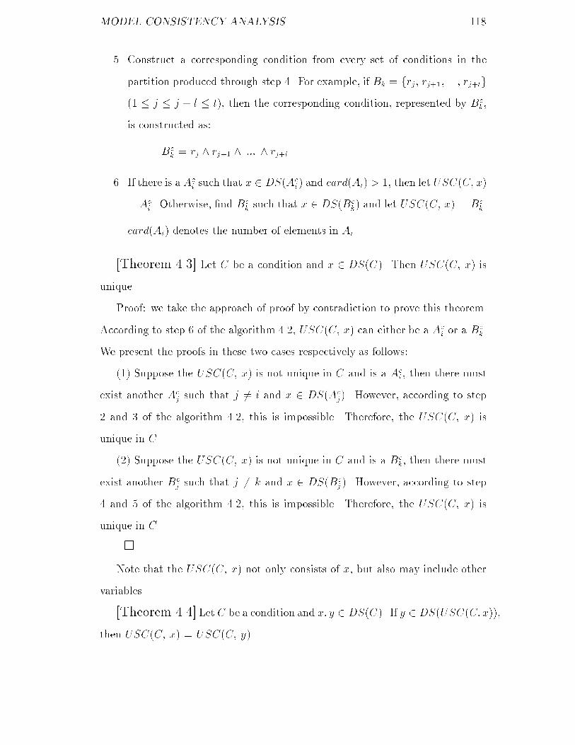
MODEL CONSISTENCY ANALYSIS ��
�� Construct a corresponding condition from every set of conditions in the
partition produced through step �� For example if Bk � frj rj� ��� rjlg
�� � j � j � l � t� then the corresponding condition represented by Bck
is constructed as�
Bck � rj � rj� � ��� � rjl
�� If there is a Aci such that x � DS�Ac
i � and card�Ai� � � then let USC�C� x�
� Aci � Otherwise �nd Bc
k such that x � DS�Bck� and let USC�C� x� � Bc
k�
card�Ai� denotes the number of elements in Ai�
�Theorem ���� Let C be a condition and x � DS�C�� Then USC�C� x� is
unique�
Proof� we take the approach of proof by contradiction to prove this theorem�
According to step � of the algorithm ��� USC�C� x� can either be a Aci or a Bc
k�
We present the proofs in these two cases respectively as follows�
��� Suppose the USC�C� x� is not unique in C and is a Aci then there must
exist another Acj such that j �� i and x � DS�Ac
j�� However according to step
� and � of the algorithm ��� this is impossible� Therefore the USC�C� x� is
unique in C�
��� Suppose the USC�C� x� is not unique in C and is a Bck then there must
exist another Bcj such that j �� k and x � DS�Bc
j �� However according to step
� and � of the algorithm ��� this is impossible� Therefore the USC�C� x� is
unique in C�
�
Note that the USC�C� x� not only consists of x but also may include other
variables�
�Theorem ���� Let C be a condition and x� y � DS�C�� If y � DS�USC�C� x��
then USC�C� x� � USC�C� y��
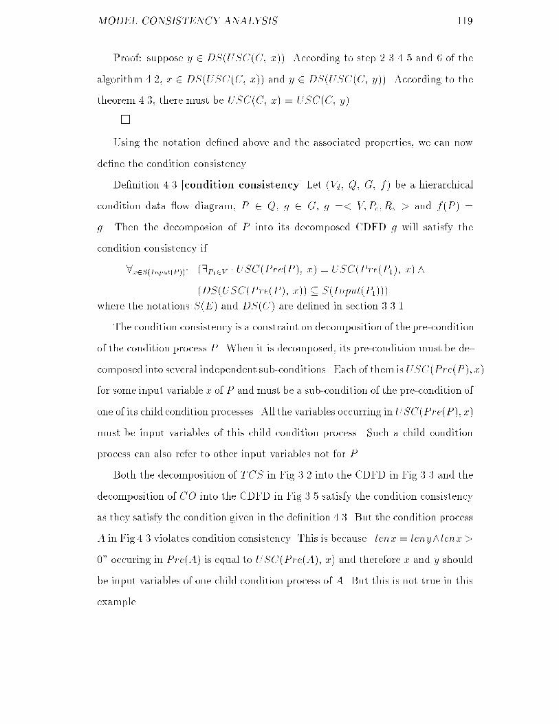
MODEL CONSISTENCY ANALYSIS ���
Proof� suppose y � DS�USC�C� x��� According to step � � � � and � of the
algorithm ��� x � DS�USC�C� x�� and y � DS�USC�C� y��� According to the
theorem ��� there must be USC�C� x� � USC�C� y��
�
Using the notation de�ned above and the associated properties we can now
de�ne the condition consistency�
De�nition ��� �condition consistency� Let �Vd� Q� G� f� be a hierarchical
condition data �ow diagram P � Q g � G g �� V�Pc� Rs � and f�P � �
g� Then the decomposion of P into its decomposed CDFD g will satisfy the
condition consistency if
x�S�Input�P ��� ��P��V � USC�Pre�P �� x� � USC�Pre�P��� x� �
�DS�USC�Pre�P �� x�� � S�Input�P����
where the notations S�E� and DS�C� are de�ned in section ������
The condition consistency is a constraint on decomposition of the pre�condition
of the condition process P � When it is decomposed its pre�condition must be de�
composed into several independent sub�conditions� Each of them is USC�Pre�P �� x�
for some input variable x of P and must be a sub�condition of the pre�condition of
one of its child condition processes� All the variables occurring in USC�Pre�P �� x�
must be input variables of this child condition process� Such a child condition
process can also refer to other input variables not for P �
Both the decomposition of TCS in Fig ��� into the CDFD in Fig ��� and the
decomposition of CO into the CDFD in Fig ��� satisfy the condition consistency
as they satisfy the condition given in the de�nition ���� But the condition process
A in Fig ��� violates condition consistency� This is because �lenx � leny�lenx �
�� occuring in Pre�A� is equal to USC�Pre�A�� x� and therefore x and y should
be input variables of one child condition process of A� But this is not true in this
example�

MODEL CONSISTENCY ANALYSIS ���
��� Diagrammatical Consistency
Besides the consistency discussed above there is another consistency diagram�
matical consistency which should also be maintained when constructing the de�
composed CDFD of a condition process�
We start the discussion of this issue by examining the CDFD in Fig ����
x
y A
B
G
F
C
C
C
C
t
t
t
t
x
y
2
1
3
4
1
2
3
4
1
1
Figure ���� Violation of diagrammatical consistency
Suppose data through t� and t� are available after �ring of the condition
process A then after �ring of the condition processes B and G data through t�
and t� are available to condition process F � If data through t� and t� are available
at di�erent time then it will cause �ring of F twice and consequently produce
available data through x� and y� twice� According to the Axiom A�� and Rule
A�� given in section ����� this CDFD cannot be the decomposed CDFD of any

MODEL CONSISTENCY ANALYSIS ���
condition process� If data through t� and t� are available at the same time then it
will not cause �ring of F due to the de�nition of the operator �� The same reason
again prevents this CDFD from being the decomposed CDFD of any condition
process�
Therefore it is necessary to build a rule to prevent this kind of contradiction
within a CDFD� This rule is called diagrammatical consistency�
De�nition ��� �diagrammatical consistency� Let g �� V�Pc� Rs � be a
CDFD� It is diagrammatically consistent if it passes the test imposed by algorithm
����
Algorithm ����
�� Construct the set of all output variables of all condition processes in V as
follows�
ODC�g� � fx j �P�V � x � S�Output�P ��g
�� Build the data relation matrix Md based on ODC�g� using the following
principle�
� Every row corresponds to one variable in ODC�g��
� Every column corresponds to one variable in ODC�g��
� Initially set every entry in the matrix to ��
� For any condition process P � V and any output variable x � ODC�g�
if x � S�Input�P �� and y � S�Output�P �� then let Md�x� y� � ��
�� For any x � ODC�g� let Md�x� x� � ��
�� Obtain the transitive closure Md of Md �the Warshall algorithm �Tremblay
�� can be used for e�ciency��
�� Do the following test for g�

MODEL CONSISTENCY ANALYSIS ���
For every x� y� z � ODC�g� P�� P� � V � � f���g x� y �d Output�P��
and z � S�Output�P���� If Md �x� z� � M
d �y� z� � � then try to �nd t�� t� �
ODC�g� satisfying� t�� t� � S�Input�P��� � �Md �x� t�� � M
d �y� t�� � �� �
t� � t� �d Input�P��� If such t� and t� cannot be found then g fails this
test�
�� If g does not fail the test in previous step then it passes the test�
Note that the transitive closure Md re�ects all the pathes � a path here means
a sequence of variables� from some output variables to other output variables
through the associated condition processes in g�
For example let g denote the CDFD in Fig ���� Hence ODC�g� � ft�� t�� t�� t�� x�� y�g�
The data relation matrix Md and its transitive closure Md are constructed which
is expressed in Fig ��� and Fig ��� respectively where each empty position in the
matrixes represents zero�
Md �
�������������������
t� t� t� t� x� y�
t� � �
t� � �
t� � � �
t� � � �
x� �
y� �
������������������
Figure ���� Data relation matrix
Because t� � t� �d Output�A� x� � S�Output�F �� t� � t� �d Input�F � and
Md �t�� t�� � M
d �t�� t�� � � and the operator � between t� and t� is di�er�
ent from the operator � between t� and t� this CDFD is not diammgratically
consistent�

MODEL CONSISTENCY ANALYSIS ���
Md �
�������������������
t� t� t� t� x� y�
t� � � � �
t� � � � �
t� � � �
t� � � �
x� �
y� �
������������������
Figure ���� Transitive closure of the Data relation matrix

Chapter �
Internal Consistency Analysis
The internal consistency analysis is to address the issue of whether the pre� and
post�conditions of condition processes within the decomposed CDFD of a non�
terminal condition process can maintain the Rule F�� given in section ������
To do this we need to deal with three problems� The �rst one is how to
guarantee that the post�condition of a condition process is consistent with input
data availability� The second one is how to guarantee the pre� and post�conditions
of a condition process are consistent with respect to the Axiom F�� given in the
same section as Rule F��� The last one is how to guarantee the Rule F�� given
in the same section as Rule F�� to be maintained by the pre� and post�conditions
of every condition process within a CDFD�
��� Consistency between Postconditions and In
put Data Availability
For the sake of simplicity this kind of consistency is called Post�Avl consistency�
We start the discussion of this issue with the example given in Fig ���� If the post�
condition of the condition process P is speci�ed as Post�P � � �l � x� y� it will
���

INTERNAL CONSISTENCY ANALYSIS ���
cause a contradiction between the post�condition and the input data availability�
This contradiction prevents Post�P � from being satis�ed by the output variable
after any �rings of the condition process P � This is because only when data
through one of x and y is available �namely one of x and y is de�ned� and the
other one is unde�ned does �ring of P occur but to let Post�P � be true needs
both x and y are de�ned�
x
y
lP
Pre(P)
Figure ���� A condition process
We can now generalize this kind of situation explained above and give a precise
de�nition of this kind of consistency� To be comprehensive we need to restate
the Property � of a condition process given in section ����� as follows�
The output data expression of the condition process P is given in disjunctive
normal form
Output�P � � Y� � Y� � ��� � Ym
and PD�So�Y��� So�Y��� ���� So�Ym��
and the post�condition is a disjunction
Post�P � � C� C� ��� Cm
such that
i�����m���j�����m� � So�Yi� � DS�Cj��
where So�Yi� � S�Yi� � S�Output�P �� for i � ����m�

INTERNAL CONSISTENCY ANALYSIS ���
Since we will often use this concept later we call such a post�condition standard
post�condition� Based on this concept and the associated notations the Post�Avl
consistency is de�ned as follows�
De�nition ��� �Post�Avl consistency� Let Cj � C�j C�
j ��� Cqj be a
disjunctive normal form � � j � m Input�P � � X� � X� � ��� � Xn� The
condition process P satis�es Post�Avl consistency if for each Cj the following
condition is satis�ed�
k�����q���i�����n� �DS�Ckj � � S�Input�P �� �� �
�� DS�Ckj � � S�Xi� �� �
This de�nition also provides a way to check whether a condition process satis�
�es the Post�Avl consistency� For example if the post�condition of the condition
process P in Fig ��� is speci�ed as Post�P � � �l � x � � l � y � � then it
satis�es the Post�Avl consitency as each of the relation expressions l � x� � and
l � y � includes only one input variable x or y in the input data expression
x� y�
��� Consistency between Pre and Postconditions
We simply call this kind of consistency Pre�Post consistency in the discussion
below�
De�nition ��� �Pre�Post consistency� The pre� and post�conditions of a
condition process satisfy the Pre�Post consistency if it satis�es the Axiom F��
�given in section �������
A way of checking whether a condition process satis�es the Pre�Post consist�
ency can be worked out based on this de�nition� Before expressing it formally let
us �rst study an example to see what problem with the pre� and post�conditions
of a condition process could prevent it from satis�ng the Axiom F��� Suppose
the pre� and post�conditions of the condition process P in Fig ��� are speci�ed as

INTERNAL CONSISTENCY ANALYSIS ��
Pre�P � � x � � y � � Post�P � � �l � x� �� l � � l � ���y� then after the
�ring of P terminates the post�condition may not be true under the assumption
that the pre�condition is true when �ring occurs� Two cases contribute to this�
If data through x is available and y is unde�ned after the �ring of P terminates
there does not exist any data through l to satisfy the condition l � x� �� l � �
consequently the Post�P � cannot be true� If data through y is available and x is
unde�ned when y � � after the �ring of P terminates there does not exist any
data through l to satisfy the condition l � ���y either the Post�P � therefore
cannot be true�
Based on this analysis the way of checking the Pre�Post consistency can now
be stated� Beforehand we need a notion de�ned as follows�
De�nition ��� �valid condition� The condition C is vaild if it satis�es the
condition�
��C � false� and
x��x�� ���� xn � C�x�� x�� ���� xn� �� �
C � false indicates false can be derived from C by logical inference�
For example the condition x � � � x � l � l � � is invalid as x � � � x �
l � l � � � false� The condition x � ��y is also invalid since when y � � it fails
to yield a truth value namely it satis�es the second condition in the de�nition
����
�Theorem ���� Let P be a condition process S�Input�P �� � fx�� x�� ���� xng
and S�Output�P �� � fy�� y�� ���� ytg be its all input and output variables Pre�P �
is valid and Post�P � � C� C� ��� Cm be its standard post�condition� Then
P violates the Pre�Post consistency if every Ci �i�����m� satis�es
�a� Pre�P � � Ci � false or
�b� �x��x������xq�Dom�Input�P ���y��y������yt�Dom�Output�P �� � Pre�P ��x�� x�� ���� xq� �
�Ci�x�� x�� ���� xq� y�� y�� ���� yt� � ��
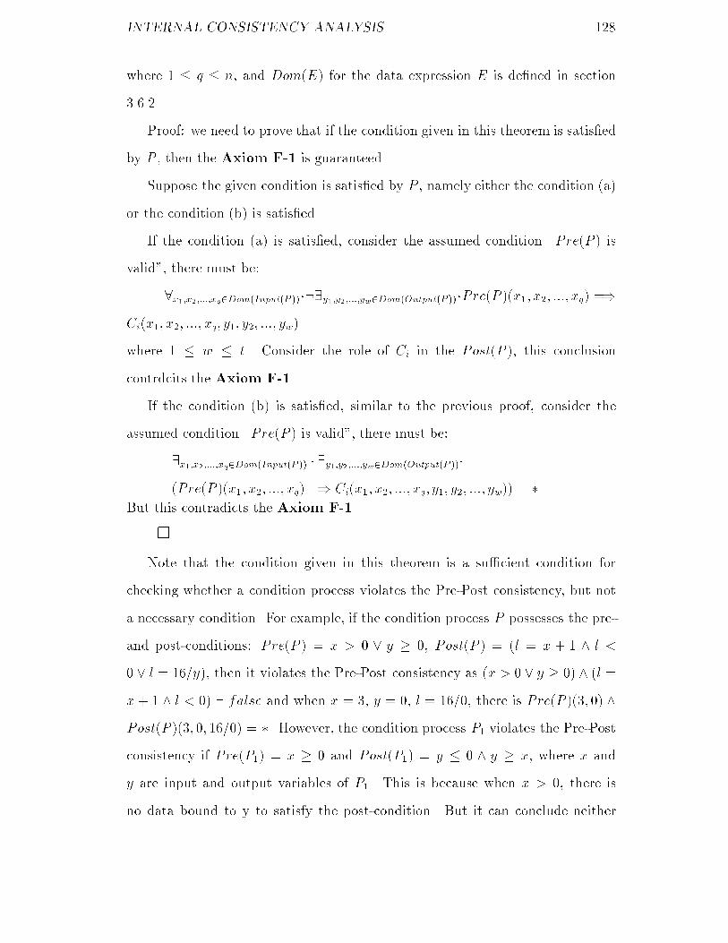
INTERNAL CONSISTENCY ANALYSIS ��
where � � q � n and Dom�E� for the data expression E is de�ned in section
������
Proof� we need to prove that if the condition given in this theorem is satis�ed
by P then the Axiom F�� is guaranteed�
Suppose the given condition is satis�ed by P namely either the condition �a�
or the condition �b� is satis�ed�
If the condition �a� is satis�ed consider the assumed condition �Pre�P � is
valid� there must be�
x��x������xq�Dom�Input�P �����y��y������yw�Dom�Output�P ���Pre�P ��x�� x�� ���� xq� ��
Ci�x�� x�� ���� xq� y�� y�� ���� yw�
where � � w � t� Consider the role of Ci in the Post�P � this conclusion
contrdcits the Axiom F���
If the condition �b� is satis�ed similar to the previous proof consider the
assumed condition �Pre�P � is valid� there must be�
�x��x������xq�Dom�Input�P �� � �y��y������yw�Dom�Output�P ���
�Pre�P ��x�� x�� ���� xq� �� Ci�x�� x�� ���� xq� y�� y�� ���� yw�� � �
But this contradicts the Axiom F���
�
Note that the condition given in this theorem is a su�cient condition for
checking whether a condition process violates the Pre�Post consistency but not
a necessary condition� For example if the condition process P possesses the pre�
and post�conditions� Pre�P � � x � � y � � Post�P � � �l � x � � � l �
� l � ���y� then it violates the Pre�Post consistency as �x � � y � �� � �l �
x � � � l � �� � false and when x � � y � � l � ���� there is Pre�P ���� �� �
Post�P ���� �� ����� � �� However the condition process P� violates the Pre�Post
consistency if Pre�P�� � x � � and Post�P�� � y � � � y � x where x and
y are input and output variables of P�� This is because when x � � there is
no data bound to y to satisfy the post�condition� But it can conclude neither

INTERNAL CONSISTENCY ANALYSIS ���
�x � �� � �y � � � y � x� � false nor �x�Dom�Input�P����y�Dom�Output�P��� � ��x �
�� � �y � � � y � x� � ���
��� Consistency among Condition Processes
We simply call this kind of consistency successor Post�Pre consistency�
De�nition ��� �successor Post�Pre consistency� A condition process satis�
�es the successor Post�Pre consistency if it satis�es the Rule F�� given in section
������
Within a CDFD condition processes are connected according to the successor
relation� Therefore to guarantee the successor Post�Pre consistency for every
condition process a necessary and su�cient condition is to let a proper com�
bination of the post�conditions of its predecessors implies its pre�condition� To
describe this principle formally we need the following notation�
Notation�
� SPC�P� x� � USC�Post�P �� x� dentoes the sub�condition Ci of the post�
condition of the condition process P such that x � S�Ci� where Post�P � �
C�C����Cn is a standard post�condition where the notation USC�C� x�
is de�ned in section ���� The SPC is short for Sub�Post�Condition�
� Op�x� represents the condition process whose one output variable is x�
� POSTp�x� � SPC�Op�x�� x� if x is an output variable of a condition process
within a CDFD g� POSTp�x� � USC�Pre�P �� x� if x is an external input
variable of g and g is the decomposed CDFD of the condition process P �
Based on this notation the principle of checking whether a condition process
satis�es the successor Post�Pre consistency is expressed through the theorem ���
below�

INTERNAL CONSISTENCY ANALYSIS ���
�Theorem ���� Let g be the decomposed CDFD of the condition process P
P� be a condition process in g Input�P�� � X��X�� ��� �Xn be in disjunctive
normal form� Then a necessary and su�cient condition for P� to satisfy the
successor Post�Pre consistency is
i�����n� � S�Xi� � fx�� x�� ���� xmg �� �POSTp�x�� � POSTp�x�� � ��� �
POSTp�xm� � Pre�P���
Proof� we need to prove two things� The �rst one is to prove that when the
condition given in this theorem is satis�ed the Rule F�� is guaranteed� The
second one is to prove the vice versa�
��� Assume that the condition given in this theorem is satis�ed� Since data
through x� x� ��� xn are available if and only if both data through some vari�
ables of x� x� ��� xn which are input variables of the parent condition process
are available �actually they are external input variables of g� and �rings of the
condition processes whose output variables include the others of x� x� ��� xn
occur and terminate there must be POSTp�x�� � true POSTp�x�� � true ���
POSTp�xn� � true when data through x� x� ��� xn are available according to
the Axiom F��� Because POSTp�x���POSTp�x��� ����POSTp�xm� � Pre�Q�
the Rule F�� must be satis�ed�
��� Suppose the Rule F�� is satis�ed� We will take the approach of proof by
contradiction to prove the condition given in this theorem is therefore guaranteed�
Assume the given condition in this theorem is not true then there must exist
a group of available data bound to x� x� ��� xn such that POSTp�x�� � true
POSTp�x�� � true ��� POSTp�xn� � true but not Pre�Q�� This conclusion
contradicts the Rule F���
�
When proving a condition process satis�es the successor Post�Pre consistency
using the rule presented in this theorem we may need the Rule F�� �given in

INTERNAL CONSISTENCY ANALYSIS ���
section ������ and the following rule of inference�
Rule I��
C �� C�
C� � Cp
C � Cp
where C C� and Cp are all conditions�
For example to prove whether the condition process CO in Fig ��� satis�es
the successor Post�Pre consistency we need to prove the following assertions
according to the theorem ����
�� POSTp�s�� � Pre�CO�
�� POSTp�w�� � Pre�CO�
�� POSTp�t� � POSTp�e� � Pre�CO�
In fact as t and e are two external input variables of the CDFD including CO the
POSTp�t� � USC�TCS� t� POSTp�e� � USC�TCS� e� where the TCS is the
parent condition process of CO� According to the de�nition of the notation USC
we have USC�TCS� t� � USC�TCS� e� � �dome � t�cardt � ��� Furthermore
according to the de�nition of the notation POSTp�x� we have POSTp�s�� �
SPC�SR� s�� POSTp�w�� � SPC�WR� w��� According to the de�nition of the
notation SPC�P� x� we have SPC�SR� s�� � �elem s� � s � len s� � card s�
and SPC�WR� w�� � �elemw� � w � lenw� � cardw�� Therefore to prove the
assertions given above is equivalent to proving the following assertions�
�� elem s� � s � len s� � card s � Pre�CO�
�� elemw� � w � len w� � card w � Pre�CO�
�� dom e � t � card t � � � Pre�CO�

INTERNAL CONSISTENCY ANALYSIS ���
Here we only give the detailed proof for the �rst assertion� The proofs for the
other two assertions are omitted as they are similar�
Since Pre�SR� � card s � � using Rule F�� we obtain�
elem s� � s � len s� � card s � card s � �
Therefore len s� � �� Consider
Pre�CO� � �len s� � � dom e � t � card t � � len w� � ��
we have
len s� � � � Pre�CO�
Therefore
elem s� � s � len s� � card s � Pre�CO�
�
If there exists a cycle which is a path �sequence of data �ows� from one
condition process �through others� to itself in a CDFD the principle of proving
whether such a condition process satis�es the successor Post�Pre consistency is
the same as described in the theorem ����
For example suppose a cycle is as shown in Fig ���� The variables are declared
as�
VAR
x y z l � N
and the post�conditions of condition processes A and B are�
Post�A� � ��z � x � �� �y � l � ���
Post�B� � �l � z � ��
In order to prove that both A and B satisfy the successor Post�Pre consistency
we need to complete the following proofs�
�� POSTp�x� � x � � l � ��
�� POSTp�l� � x � � l � ��
�� POSTp�z� � z � ��

INTERNAL CONSISTENCY ANALYSIS ���
B
z > 0
xA
y
z
l
x > 0 ∨ l > 0
Figure ���� A CDFD with a cycle

INTERNAL CONSISTENCY ANALYSIS ���
This proof is omitted as it applies the same principle as the proof of CO does�
��� Internal Consistency
Based on the results achieved in previous sections the internal consistency can
now be discussed� As described in the begining of this chapter the internal
consistency analysis is to address the issue of whether the pre� and post�conditions
of condition processes within the decomposed CDFD of a non�terminal condition
process can maintain the Rule F�� given in section ������ The objective of this
section is to develop a rule for ensuring the internal consistency in a hierarchical
condition data �ow diagram� First we formally de�ne the internal consistency
as follows�
De�nition ��� �internal consistency� The decomposition of a condition pro�
cess into its decomposed CDFD satis�es the internal consistency if there exists a
condition C� to satisfy�
fPre�P �g P fC�g
fPre�P �g g fC�g
For the sake of simplicity we introduce a notion which will often be used later�
De�nition ��� �valid condition process� A condition process is a valid condi�
tion process if it satis�es Post�Avl consistency Pre�Post consistency and successor
Post�Pre consistency�
�Theorem ���� Let g be the decomposed connected CDFD of the condition
process P the decomposition of P into g be structurally consistent every con�
dition process in g be a valid condition process and the Post�P � be produced
through the algorithm ��� below� Then the decomposition of P into g must
satisfy the internal consistency namely

INTERNAL CONSISTENCY ANALYSIS ���
fPre�P �g P fPost�P �g
fPre�P �g g fPost�P �g
Proof� suppose all the assumed conditions given in this theorem are satis�ed�
According to the step � and � of the algorithm ��� each PATHi corresponds
to a group of condition processes which can cause �ring of g� According to step
� of this algorithm the corresponding condition COPi of PATHi is PS�P�� �
PS�P�� � ��� � PS�Pk�� As every condition process is a valid condition process
as long as g is �red along the corresponding condition processes P� P� ��� Pk
and make data through the corresponding output variables available the COPi
must be true after the �ring terminates �keep in mind that the post�condition of
a condition process usauslly describes the relationship between output and input
variables therefore input variables usaually occur in the post�condition�� Since
the path expression produced by the step � of the algorithm ���
PATH� � PATH� � ��� � PATHq
indicates all the groups of condition processes which can cause �ring of g and
the decomposition of P into g is structurally consistent �ring of g is caused
by exactly one group of condition processes every times and exactly one of the
COP� COP� ��� COPq is true after the termination of the �ring� Therefore
the Post�P � � COP� COP� ��� COPq is true after the termination of the
�ring of g every times� According to the Rule A�� given in section ����� and the
assumption that the decomposition of P into g is structurally consistent �ring
of P is equivalent to �ring of g� Therefore we have
fPre�P �g P fPost�P �g
fPre�P �g g fPost�P �g
�
Algorithm ����
�� Perform steps � � � � and � of the algorithm ��� to obtain the expression

INTERNAL CONSISTENCY ANALYSIS ���
PATH� � PATH� � ��� � PATHt where each PATHi �i�����t� denotes
a path which is a combination of transformations joined together only by
���s but not ���s in g�
�� Perform step � of the algorithm ��� to test each path PATHi to see whether
there is any transformation left eventually� If there is not delete this
PATHi from the expression obtained by step � of this algorithm� Oth�
erwise remain this PATHi in that expression� According to this principle
we convert that expression into
PATH� � PATH� � ��� � PATHq
where q � t�
�� Obtain a condition from this path expression by the following steps�
�a� Let L� �� R� be a transformation in PATHi the corresponding
condition process be P� S�R�� � fy�g� Then produce the condition
denoted by PS�P�� for replacing this transformation in the PATHi as
follows�
PS�P�� � POSTp�y��
�b� Let PATHi be
L� �� R� � L� �� R� � ��� � Lk �� Rk
Derive the corresponding condition COPi of PATHi as follows�
COPi � PS�P�� � PS�P�� � ��� � PS�Pk�
where k � � and Pj �j � ����k� is the corresponding condition process
of the single transformation Lj �� Rj�
�c� Obtain the corresponding condition of the path expression by convert�
ing
PATH� � PATH� � ��� � PATHq

INTERNAL CONSISTENCY ANALYSIS ��
into
COP� COP� ��� COPq�
Use FDP �g� to denote this �nal predicate disjunction� Namely
FDP �g� � COP� COP� ��� COPq�
Then let Post�P � � FDP �g��
�
�Theorem ���� Let g be the disconnected decomposed CDFD of the condi�
tion process P g consist of the connected CDFD g� g� ��� gn every condition
process in gi �i � ����n� is a valid condition process� FDP �g�� FDP �g�� ���
FDP �gn� are conditions produced through the algorithm ��� and the decom�
position of P into g is structurally consistent� Then the decomposition of P
into g satis�es the internal consistency with respect to Post�P � � FDP �g��
FDP �g�� ��� FDP �gn��
Proof� Assume the given conditions are satis�ed� Then according to the
algorithm ��� whenever one of g� g� ��� gn is �red and after the �ring terminates
one of FDP �g�� FDP �g�� ��� FDP �gn� is true� From the assumption that the
decomposition of P into g is structurally consistent and the Rule A�� �given in
section ������ we know that �ring of g is equivalent to �ring of P and whenever
g is �red exactly one of g� g� ��� gn is �red� Therefore exactly one of FDP �g��
FDP �g�� ��� FDP �gn� is true after the �ring terminates� Consequently the
Post�P � � FDP �g��FDP �g�� ���FDP �gn� is true after �ring of g terminates
every times� Accordingly according to the de�nition of the internal consistency
the decomposition of P into g satis�es the internal consistency with respect to
Post�P � � FDP �g�� FDP �g�� ��� FDP �gn��
�
For example the decomposed CDFD of the condition process CO in Fig ��� is

INTERNAL CONSISTENCY ANALYSIS ��
the CDFD in Fig ��� which is a disconnected CDFD� It consists of three connected
CDFDs� We name them g� g� and g� respectively� g� consists of the condition
process SC� g� consists of the condition processes TR PC MC BC and TS
and g� consists of WC� Then the Post�CO� is produced through the following
steps�
�� Use the algorithm ��� to compute FDP �g�� FDP �g�� and FDP �g�� as
follows�
FDP �g�� � PS�SC� � POSTp�s�� � Post�SC� � EXAM�s� s��
FDP �g�� � PS�WC� � POSTp�w�� � Post�WC� � EXAM�w�� w��
FDP �g�� � POSTp�t��� � POSTp�t��� � POSTp�t���
� POSTp�tc�� � POSTp�tc��
� POSTp�tc�� � POSTp�ts� � POSTp�l�
� �elem t�� � fx j x � t � e�x� � Ph�Dg �
elem t�� � fx j x � t � e�x� � M�Scg �
elem t�� � fx j x � t � e�x� � B�Scg �
len t�� � len t�� � len t�� � card t� �
�if len t�� � � then EXAM�t��� tc�� else dom tc� � �� �
�if len t�� � � then EXAM�t��� tc�� else dom tc� � �� �
�if len t�� � � then EXAM�t��� tc�� else dom tc� � �� �
�let tc� y tc� y tc� � a in dom a � elem ts �
IS�SORTED�ts� a� � l � fx j x � dom a � a�x� � ��g��

INTERNAL CONSISTENCY ANALYSIS ���
�� Post�CO� � FDP �g�� FDP �g�� FDP �g��
� Post�SC� Post�WC� Post�TR� �
Post�PC� � Post�MC� � Post�BC� � Post�TS�
� EXAM�s�� s�� EXAM�w�� w��
��elem t�� � fx j x � t � e�x� � Ph�Dg �
elem t�� � fx j x � t � e�x� � M�Scg �
elem t�� � fx j x � t � e�x� � B�Scg �
len t�� � len t�� � len t�� � card t� �
�if len t�� � � then EXAM�t��� tc�� else dom tc� � �� �
�if len t�� � � then EXAM�t��� tc�� else dom tc� � �� �
�if len t�� � � then EXAM�t��� tc�� else dom tc� � �� �
�let tc� y tc� y tc� � a in dom a � elem ts �
IS�SORTED�ts� a� � l � fx j x � dom a � a�x� � ��g���
The post�condition of a non�terminal condition process which is derived from
its decomposed CDFD can be used for proving this non�terminal condition process
to be a valid condition process�
A FGSL speci�cation is valid for being the basis of the further system devel�
opment if its associated hierarchical condition data �ow diagram satis�es both
the model consistency and the internal consistency�

Chapter �
Philosophy of FGSM
A sound example is given in this chapter for demonstrating the philosophy of the
formal graphic speci�cation method �FGSM�� The philosophy of FGSM presents
an approach of capturing requirements and constructing the corresponding FGSL
speci�cations�
��� Process of Requirement Analysis Using FGSL
The principle of FGSM is that a requirement analysis is carried out concurrently
with the construction of the corresponding FGSL speci�cation� The purpose
of the requirement analysis is to produce the FGSL speci�cation� The FGSL
speci�cation is a formal expression of the requirement �Liu ����
The process of requirement analysis to produce the FGSL speci�cation is
divided into three steps� They are called Model Real World Data Analysis and
Specify Functionality�
����� Model Real World
The task of the �rst step Model Real World is to construct a hierarchical condition
data �ow diagram with the lack of some information� Each condition process in
���

PHILOSOPHY OF FGSM ���
this hierarchical condition data �ow diagram possesses a name all necessary
input and output variables� The relationships �� and �� among input or output
variables are determined� But there are no types being de�ned for associating all
the variables with them and the pre� and post�conditions of condition processes
are not speci�ed�
This hierarchical condition data �ow diagram is produced based on the phys�
ical model of the system to be developed in the real world such as a bank man�
agement system and an university management system etc� Since without under�
standing the problem to be solved it is impossible to work out the requirements
completely and correctly for the functionality of the system� Therefore the most
important and necessary thing to do at the �rst step of requirement analysis is
to describe the problem itself at abstract level� All input and output variables
of condition processes which represent the corresponding data are used based on
the imagination �or abstract thinking� of their structures and properties in the
real world� The relationships between input or output variables are determined
based on the problem to be solved�
The construction of the hierarchical condition data �ow diagram at the �rst
step starts with drawing the top level CDFD �might be a single condition process
with the lack of pre� and post�conditions� and then proceed to other CDFDs
by decomposing condition processes� For every drawn condition process the
following things need to be done in turn�
�� Determine the relationships between input or output variables�
�� Decompose the condition process into its decomposed CDFD �if necessary��
�� Prove the decomposition of the condition process into its decomposed CDFD
to satisfy the structural consistency�
�� Prove the decomposed CDFD to satisfy the diagrammatical consistency�

PHILOSOPHY OF FGSM ���
After the whole hierarchical condition data �ow diagram is established the
proof for guaranteeing this hierarchical condition data �ow diagram to satisfy the
global consistency must be completed�
����� Data Analysis
To specify the functionality of condition processes precisely we need to describe
the pre� and post�conditions for condition processes� Without determining the
structures and properties of the data represented by the variables which are used
in the hierarchical condition data �ow diagram produced at the �rst step it is
impossible to complete this task� The objective of the second step Data Analysis
is therefore to determine the structures and properties of the data by analysis
based on the information from the real world� The way of doing this is to de�ne
the necessary types and declare the variables with the corresponding types� Type
invariants for the types need to be decided if necessary� Furthermore the type
and variable declarations must obey the rule for the scope of types and variables�
����� Specify Functionality
Based on the result achieved from the �rst two steps the task of the third step
Specify Functionality is to describe the pre�conditions for every condition process
and the post�conditions for every terminal condition process in the hierarchical
condition data �ow diagram produced at the �rst step� During this process if
some functions are necessary to be used they must be de�ned in the de�nitions
of the corresponding terminal condition processes�
After specifying pre� and post�conditions as described above the following
things need to be done�
�� Prove the decomposition of every non�terminal condition process into its
decomposed CDFD to satisfy the condition consistency�

PHILOSOPHY OF FGSM ���
�� Prove every condition process to be a valid condition process� Namely it
satis�es the Post�Avl consistency the Pre�Post consistency and the suc�
cessor Post�Pre consistency�
�� Prove the decomposition of every non�terminal condition process into its
decomposed CDFD to satisfy the internal consistency�
In practice the result achieved at each step of these three steps might be
changed or developed when other steps are carried out� That is during the
second step the hierarchical condition data �ow diagram achieved at the �rst
step might need to be modi�ed according to the data analysis� When pre� and
post�conditions of condition processes are speci�ed at the third step it might be
necessary to amend the results achieved from the �rst two steps to meet the need
of describing the functionality of condition processes� This process is re�ected
by the diagram in Fig ��� in which the broken lines with short dash indicate
optional actions the broken lines with long dash represent �production� and the
solid lines represent the compulsory actions�
Through these three steps of requirement analysis the eventual FGSL spe�
ci�cation for developing the corresponding system is produced� This speci�cation
will be the �rm basis for the further system development if it satis�es the client�s
requirement exactly� In next section a sound example will be presented for show�
ing how the philosophy of FGSM is applied in practice�
��� Example
To improve the teacher management in a department of the universities and
provide fare chances for teachers in promotion training and awarding bonus a
new proposal about the teacher management was presented at the Xi�an Jiaotong
University in early ��� The idea of this proposal is to give each teacher a total

PHILOSOPHY OF FGSM ���
Real World
Data Analysis
Specify Functionality
Model Real World
FGSL Specifications
Figure ���� Process of FGSL speci�cation construction

PHILOSOPHY OF FGSM ���
mark to represent his or her contribution for teaching research and research
funds� This total mark is derived in a certain way from the marks for teaching
research and research funds respectively� The mark for a teacher�s teaching is
given by the students according to the quality of the teaching� The mark for
a teacher�s research is given according to the quality and quantity of his or her
publications� The mark for a teacher�s research funds is given according to the
amount of the funds obtained by him or her for research� According to the total
marks of teachers the lists of teachers with their total marks for promotion
training and awarding bonus are produced� As these lists are necessary to be
reported frequently in a year this teacher management needs to be computerized
for the e�cience�
In order to provide �exible service for the teacher management this system
to be realized in the computer is wanted to be able to produce both the detailed
report on the marks for teaching research and research funds as well as the
information sources for producing these marks and the lists of teachers with their
total marks for promotion training and awarding bonus� The former is for telling
the sta�s in the department how the marks are derived and the latter is for the
administrators to make the decision of promoting teachers training teachers and
awarding bonus to teachers�
The requirement analysis to produce the speci�cation for this proposed system
using the FGSM is described as the following three steps�
Model Real World�
According to our understanding on the problem described above the hierarch�
ical condition data �ow diagram is constructed using the top�down principle� As
metioned before each condition process within this hierarchical condition data
�ow diagram lacks its pre� and post�conditions�
First the top level condition data �ow diagram is built in Fig ����

PHILOSOPHY OF FGSM ���
rc
ta
fd
rm
tm
fm
rm
tm
fmpl
tl
bl
1
2
R-T-F-Process
Total-Mark-Evaluation
nlc
1
1
2
2
cl
Figure ���� Teacher management system �incomplete�
This CDFD consists of the two condition processes R�T �F �Process and Total�
Mark�Evaluation� The R�T �F �Process standing for Research Teaching Fund
Process transforms the input data represented by rc ta fd and nlc into one of
the two group output data rm� tm� fm� and rm� tm� fm�� The former group
is for reporting the details of the marks for teaching research and obtained funds
as well as the information sources for producing these marks� The latter group
is for producing the promotion list training list and bonus list� If they and the
variable cl are available the Total�Mark�Evaluation will transform them into
the promotion list training list and bonus list represented by pl tl and bl� In
this CDFD short variables are used for keeping the diagram neat� What all the
variables stand for are listed as follows�

PHILOSOPHY OF FGSM ��
rc � research class
ta � teaching appraisal
fd � fund
nlc � new list command
rm � research mark
tm � teaching mark
fm � fund mark
cl � current list
pl � promotion list
tl � training list
bl � bonus list
The problems the condition processes R�T �F �Process and Total�Mark�Evaluation
express are still abstract and di�cult to understand� Therefore we need to de�
compose them further� First the R�T �F �Process is decomposed into another
CDFD which is shown in Fig ����
This CDFD consists of the four condition processes Identify�Command
Research�Mark�Evaluation Teaching�Mark�Evaluation and Fund�Mark�Evaluation�
The Identify�Command transforms the command �denoted by nlc� provided by
the user into a number � or � which is represented by yn for easy processing�
The Research�Mark�Evaluation produces either the research mark �denoted by
rm�� for reporting or the research mark �denoted by rm�� for the production of
the promotion list training list and bonus list� The Teaching�Mark�Evaluation
and Fund�Mark�Evaluation have the similar functions to that of the Research�
Mark�Evaluation but for producing teaching mark and bonus mark respectively
instead� In this CDFD only one new variable yn is introduced� It stands for �yes
or no��
Second the Total�Mark�Evaluation is decomposed into the CDFD in Fig ����

PHILOSOPHY OF FGSM ��
nlc
yn
yn
yn
fd
ta
rcrm
rm
tm
tm
fm
fm
1
2
1
2
1
2
IdentifyCommand
Research-Mark-Evaluation
Teaching-Mark-Evaluation
Fund-Mark-Evaluation
-
Figure ���� Decomposed CDFD of R�T �F �Process �incomplete�

PHILOSOPHY OF FGSM ���
rm
tm
fm
total-m
cl
pl
tl
bl
Obtain-Total-Mark
Produce-Final-Lists
Figure ���� Decomposed CDFD of Total�Mark�Evaluation �incomplete�
This CDFD includes the two condition processes Obtain�Total�Mark and Produce�
Final�Lists� The Obtain�Total�Mark is for producing the total mark total�m for
the concerned teacher based on the input data represented by rm� tm� and fm��
The Produce�Final�Lists updates the currently existing promotion list training
list and bonus list which are represented by cl and produces the new promotion
list �denoted by pl� training list �denoted by tl� and bonus list �denoted by bl�
separately�
Up to now without understanding the structures and properties of the con�
cerned data represented by variables we feel di�cult to decide whether there is
any condition processes needed to be decomposed further� Therefore it is ne�
cessary to go into the step of Data Analysis� But before doing this we need to
prove whether this hierarchical condition data �ow diagram at the moment sat�
is�es the structural consistency and the diagrammatical consistency� Using the

PHILOSOPHY OF FGSM ���
methods for checking the structural consistency and the diagrammatical consist�
ency presented in chapter � we can prove that every condition process and every
CDFD in this hierarchical condition data �ow diagram satisfy the structural con�
sistency and the diagrammatical consistency respectively� As the process of this
proof is tedious and demonstrates nothing new than the examples presented in
the chapter � for explaining the principle of the structural consistency and the
diagrammatical consistency it is omitted here�
Data Analysis�
To express the problem in detail which the teacher management system is
expected to solve we analysis the structures and the properties of the data used
in the corresponding hierarchical condition data �ow diagram according to their
usage in the real world� Consequently some necessary types are de�ned and the
corresponding variables are declared with these types� These type and variable
declarations are presented separately in the de�nitions of the condition processes
TOP �assumed one as metioned in the chapter �� R�T �F �Process and Total�
Mark�Evaluation in the hierarchical condition data �ow diagram represented
by the diagrams in Fig ��� Fig ��� and Fig ���� These de�nitions which are
incomplete with respect to the syntax for a complete de�nition of a condition
process are expressed as follows�
TOP
TYPE
Research�Class � compose Research�Class of
name � seq of char
publication � set of Journal
end
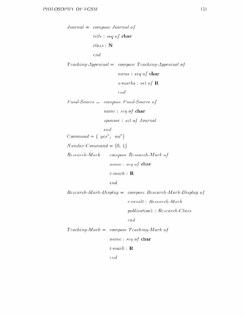
PHILOSOPHY OF FGSM ���
Journal � compose Journal of
title � seq of char
class � N
end
Teaching�Appraisal � compose Teaching�Appraisal of
name � seq of char
s�marks � set of R
end
Fund�Source � compose Fund�Source of
name � seq of char
sponsor � set of Journal
end
Command � f�yes�� �no�g
Number�Command � f�� �g
Research�Mark � compose Research�Mark of
name � seq of char
r�mark � R
end
Research�Mark�Display � compose Research�Mark�Display of
r�result � Research�Mark
publication� � Research�Class
end
Teaching�Mark � compose Teaching�Mark of
name � seq of char
t�mark � R
end

PHILOSOPHY OF FGSM ���
Teaching�Mark�Display � compose Teaching�Mark�Display of
t�result � Teaching�Mark
student�mark � set of R
end
Fund�Mark � compose Fund�Mark of
name � seq of char
f �mark � R
end
Fund�Mark�Display � compose Fund�Mark�Display of
f �result � Fund�Mark
fund�source � set of Journal
end
Personal�Mark � compose Personal�Mark of
name � seq of char
number � R
end
Current�Lists � compose Current�Lists of
promotion � seq of Personal�Mark
training � seq of Personal�Mark
bonus � seq of Personal�Mark
end
INV
inv�Current�Lists�mk�Current�Lists�p� t� b�� �
len p � len t � len b
VAR
rc � Research�Class
ta � Teaching�Apprisal

PHILOSOPHY OF FGSM ���
fd � Fund�Source
nlc � Command
yn � Number�Command
rm� � Research�Mark�Display
rm� � Research�Mark
tm� � Teaching�Mark�Display
tm� � Teaching�Mark
fm� � Fund�Mark�Display
fm� � Fund�Mark
cl � Current�Lists
pl tl bl � seq of Personal�Mark
� � �
END�TOP
where � � � denotes the information which is needed to achieve in the step of
Specify Functionality later on�
R�T �F �Process �TOP
VAR
yn � Number�Command
� � �
END�R�T �F �Process
Total�Mark�Evaluation �TOP
VAR
total�m � Personal�Mark
� � �
END�Total�Mark�Evaluation
As there is no any type or variable declarations in the de�nitions of other
condition processes occurring in the concerned hierarchical condition data �ow

PHILOSOPHY OF FGSM ���
diagram it is not necessary to give their de�nitions at this stage�
After this data analysis it is realized that the task of obtaining the mark for a
teacher�s research has to be completed by three condition processes separately as
the algorithms for producing the marks from the �rst class second class and third
class publications are di�erent� Therefore we return to the �rst step Model Real
World to decompose the condition process Research�Mark�Evaluation into the
CDFD in Fig ����
This CDFD consists of the �ve condition processes Classify�Publication
First�Class�Mark Second�Class�Mark Third�Class�Mark and Result�Mark�
The Classify�Publication is for dividing the publications of a teacher into the
three di�erent classes� �rst class second class and third class which are repres�
ented by fc sc and tc respectively� The processes First�Class�Mark Second�
Class�Mark and Third�Class�Mark produce the corresponding marks from the
input fc sc and tc respectively using the di�erent algorithms� The Result�Mark
processes the three marks represented by rs� rs� and rs� and produces either the
research mark for reporting or the research mark for updating the existing pro�
motion list training list and bonus list according to the input command denoted
by yn�
We can also prove that the decomposition of Research�Mark�Evaluation
into this CDFD satis�es the structural consistency and this CDFD satis�es the
diagrammatical consistency� This proof is also omitted due to the same reason as
for other condition processes and CDFDs of the concerned hierarchical condition
data �ow diagram�
Since the new variables fc sc tc rs� rs� and rs� are introduced in this
CDFD it is necessary to declare them with the suitable types� This declaration
is presented in the de�nition of Research�Mark�Evaluation as follows�
Research�Mark�Evaluation �R�T �F �Process

PHILOSOPHY OF FGSM ���
rc
fc
sc
tc
rs
rs
rs
rm
rm
1
2
3
1
2
pub-list
yn
Classify-Publication
First-Class-Mark
Second-Class-Mark
Third-Class-Mark
Result-Mark
Figure ���� Decomposed CDFD of Research�Mark�Evaluation �incomplete�

PHILOSOPHY OF FGSM ���
VAR
fc sc tc � Personal�Mark
rs� rs� rs� � Personal�Mark
pub�list � seq of Journal
� � �
END�Research�Mark�Evaluation
Specify Functionality�
Based on the result achieved through the �rst two steps Model Real World
and Data Analysis we can now undertake to specify the precise functionality
of each condition process by giving its pre� and post�conditions �but for non�
terminal condition processes only the pre�conditions are given�� As the post�
conditions are described based on the corresponding pre�conditions the way of
doing this is to describe the pre�condition for each condition process �rst under
the principle of condition consistency� Then describe the post�condition for each
terminal condition process and complete the whole speci�cation by giving the
de�nitions of all the condition processes� The complete speci�cation of the teacher
management system is as follows�
TOP
TYPE
Research�Class � compose Research�Class of
name � seq of char
publication � set of Journal
end
Journal � compose Journal of
title � seq of char
class � N
end

PHILOSOPHY OF FGSM ��
Teaching�Appraisal � compose Teaching�Appraisal of
name � seq of char
s�marks � set of R
end
Fund�Source � compose Fund�Source of
name � seq of char
sponsor � set of Journal
end
Command � f�yes�� �no�g
Number�Command � f�� �g
Research�Mark � compose Research�Mark of
name � seq of char
r�mark � R
end
Research�Mark�Display � compose Research�Mark�Display of
r�result � Research�Mark
publication� � Research�Class
end
Teaching�Mark � compose Teaching�Mark of
name � seq of char
t�mark � R
end
Teaching�Mark�Display � compose Teaching�Mark�Display of
t�result � Teaching�Mark
student�mark � set of R
end

PHILOSOPHY OF FGSM ��
Fund�Mark � compose Fund�Mark of
name � seq of char
f �mark � R
end
Fund�Mark�Display � compose Fund�Mark�Display of
f �result � Fund�Mark
fund�source � set of Journal
end
Personal�Mark � compose Personal�Mark of
name � seq of char
number � R
end
Current�Lists � compose Current�Lists of
promotion � seq of Personal�Mark
training � seq of Personal�Mark
bonus � seq of Personal�Mark
end
INV
inv�Current�Lists�mk�Current�Lists�p� t� b�� �
len p � len t � len b
VAR
rc � Research�Class
ta � Teaching�Apprisal
fd � Fund�Source
nlc � Command
yn � Number�Command
rm� � Research�Mark�Display

PHILOSOPHY OF FGSM ���
rm� � Research�Mark
tm� � Teaching�Mark�Display
tm� � Teaching�Mark
fm� � Fund�Mark�Display
fm� � Fund�Mark
cl � Current�Lists
pl tl bl � seq of Personal�Mark
FUN
The top level CDFD is as shown in Fig ����
END�TOP
rc
ta
fd
rm
tm
fm
rm
tm
fmpl
tl
bl
1
2
R-T-F-Process
Total-Mark-Evaluation
nlc
1
1
2
2
card s-marks(ta) > 0
(class(e) ≥ 1 ∧ class(e) < 4)∧ true(fd, nlc)
.
∧
∧ ∀ e ∈ publication(rc)
∧
elem promotion(cl) =elem training(cl) =elem bonus(cl) len promotion(cl) =len training(cl) =len bonus(cl)
∧
r-mark(rm ) ≥ 0t-mark(tm ) ≥ 0f-mark(fm ) ≥ 0
∧222
cl
Figure ���� Teacher management system
R�T �F �Process �TOP
VAR
yn � Number�Command

PHILOSOPHY OF FGSM ���
FUN
The decomposed CDFD of R�T �F �Process is as shown in Fig ���
END�R�T �F �Process
Total�Mark�Evaluation �TOP
VAR
total�m � Personal�Mark
FUN
The decomposed CDFD of Total�Mark�Evaluation is as shown in Fig ���
END�Total�Mark�Evaluation
Research�Mark�Evaluation �R�T �F �Process
VAR
fc sc tc � Personal�Mark
rs� rs� rs� � Personal�Mark
pub�list � seq of Journal
FUN
The decomposed CDFD of Research�Mark�Evaluation is as shown in Fig ���
END�Research�Mark�Evaluation
Identify�Command �R�T �F �Process
FUN
PRE� true
POST � if nlc � �yes� then yn � � else yn � �
END�Identify�Command
Teaching�Mark�Evaluation �R�T �F �Process
FUN
PRE� card s�marks�ta� � � � true�yn�

PHILOSOPHY OF FGSM ���
nlc
yn
yn
yn
fd
ta
rcrm
rm
tm
tm
fm
fm
1
2
1
2
1
2
IdentifyCommand
Research-Mark-Evaluation
Teaching-Mark-Evaluation
Fund-Mark-Evaluation
-
true
(class(e) ≥ 1 ∧ class(e) < 4)
∀ e ∈ publication (rc) .
card s-marks(ta) > 0∧ true(yn)
∧ true(yn)
true
Figure ��� Decomposed CDFD of R�T �F �Process

PHILOSOPHY OF FGSM ���
rm
tm
fm
cl
pl
tl
bl
Obtain-Total-Mark
Produce-Final-Lists
r-mark(rm ) ≥ 0
2
2
2
22
∧
∃ e ∈ elem promotion (cl)∩ elem training(cl) ∩elem bonus(cl) .name(e) = name(total-m)∧ number(total-m) ≥ 0
total-m
elem promotion(cl) =elem training(cl) =elem bonus(cl) len promotion(cl) =len training(cl) =
∧
len bonus(cl) ∧
t-mark(tm ) ≥ 0f-mark(fm ) ≥ 02
∧
Figure ��� Decomposed CDFD of Total�Mark�Evaluation
POST � yn � � � name�t�result�tm��� � name�ta�
� t�mark�t�result�tm��� � SUM�s�mark�ta��
� student�mark�tm�� � s�marks�ta�
yn � � � name�tm�� � name�ta�
� t�mark�tm�� � SUM�s�mark�ta��
FUNCTION
SUM � set of R �� R
SUM�s� �
if card s � � then �
else �e�s � e � SUM�s n feg�
COM
If yn is equal to � then tm� is produced� Otherwise if yn is equal to � then
tm� is produced� The function SUM is applied in the post�condition�
END�Teaching�Mark�Evaluation

PHILOSOPHY OF FGSM ���
rc
fc
sc
tc
rs
rs
rs
rm
rm
1
2
3
1
2
pub-list
yn
Classify-Publication
First-Class-Mark
Second-Class-Mark
Third-Class-Mark
Result-Mark
∀ e ∈ publication(rc). (class(e) ≥ 1 ∧ class(e) < 4)
true
true
true
number(rs ) + number(rs ) +number(rs ) ≥ 0
123
∧ true(yn, pub-list)
Figure ���� Decomposed CDFD of Research�Mark�Evaluation

PHILOSOPHY OF FGSM ���
Fund�Mark�Evaluation �R�T �F �Process
FUN
PRE� true
POST � yn � � � name�f �result�fm��� � name�fd�
� f �mark�f �result�fm��� � SUM �money�sponsor�fd��
� �����
� fund�source�fm�� � sponsor�fd�
yn � � � name�fm�� � name�fd�
� f �mark�fm�� � SUM �money�sponsor�fd�� � �����
FUNCTION
SUM �money � set of Journal �� R
SUM �money�s� �
if card s � � then �
else �e�s � e � SUM �money�s n feg�
COM
If yn is equal to � then fm� is produced� Otherwise if yn is equal to � then
fm� is produced� The idea of producing the mark for the fund obtained by a
teacher which is expressed by the post�condition is to give � mark for each �����
pounds� The function SUM �money is applied in the post�condition�
END�Fund�Mark�Evaluation
Classify�Publication �Research�Mark�Evaluation
PRE� e�publication�rc� � class�e� � � � class�e� � �

PHILOSOPHY OF FGSM ���
POST � if card publication�rc� � �
then
name�fc� � name�rc� � name�sc� � name�rc� �
name�tc� � name�rc� � card publication�fc� � � �
card publication�sc� � � � card publication�tc� � �
else
name�fc� � name�rc� �
number�fc� � feje � publication�rc� � class�e� � � �
name�sc� � name�rc� �
number�sc� � feje � publication�rc� � class�e� � � �
name�tc� � name�rc� �
number�tc� � feje � publication�rc� � class�e� � � �
elem pub�list � publication�rc� �
let length � len pub�list in
i�j�����length� � i � j �� class�pub�list�i��� class�pub�list�j��
COM
This condition process divides the publications denoted by publication�rc�
as the input data into the three group of publications denoted by number�fc�
number�sc� and number�tc� respectively as the output data of this condition
process�
END�Classify�Publication
F irst�Class�Mark �Research�Mark�Evaluation
PRE� true
POST � name�rs�� � name�fc� � number�rs�� � � � number�fc�
COM
Each �rst class publication is given the mark ��
END�First�Class�Mark
Second�Class�Mark �Research�Mark�Evaluation

PHILOSOPHY OF FGSM ���
PRE� true
POST � name�rs�� � name�sc� � number�rs�� � � � number�sc�
COM
Each second class publication is given the mark ��
END�Second�Class�Mark
Third�Class�Mark �Research�Mark�Evaluation
PRE� true
POST � name�rs�� � name�tc� � number�rs�� � � � number�tc�
COM
Each third class publication is given the mark ��
END�Third�Class�Mark
Result�Mark �Research�Mark�Evaluation
PRE� number�rs�� � number�rs�� � number�rs�� � � �
true�yn� pub�list�
POST � yn � � � name�r�result�rm��� � name�rs�� �
publication�rm�� � pub�list
yn � � � name�rm�� � name�rs�� �
r�mark�rm�� � number�rs�� � number�rs�� � number�rs��
Obtain�Total�Mark �Total�Mark�Evaluation
PRE� t�mark�tm�� � � � f �mark�fm�� � � � r�mark�rm�� � �
POST � number�total�m� � ��� � t�mark�tm�� � ��� � r�mark�rm��
� ��� � f �mark�fm��
COM
Marks for teaching research and fund contribute di�erently to the total mark
for a teacher� The teaching mark takes �� percent of the total mark as the
teaching is emphasized for a teacher� Research mark takes �� percent of the total
mark and the fund mark takes �� percent�
END�Obtain�Total�Mark

PHILOSOPHY OF FGSM ��
Produce�Final�Lists �Total�Mark�Evaluation
PRE� elem promotion�cL� � elem training�cl� � elem bonus�cl� �
len promotion�cl� � len training�cl� � len bonus�cl� �
�e�elem promotion�cl��elem training�cl��elem bonus�cl��
name�e� � name�total�m�� number�total�m�� �
POST � pl � Insert�promotion�cl�� total�m� �
tl � Insert�training�cl�� total�m��
bl � Insert�bonus�cl�� total�m�
FUNCTION
Insert � �l � seq of Personal�Mark d � Personal�Mark�
r � seq of Personal�Mark
pre� �e�elem l � name�e� � name�d�
post� elem r � elem l � len r � len l �
�i�����len r� � name�r�i�� � name�d� �
�i �� � � i �� len r ��
�number�r�i�� � number�r�i� ��� �
number�r�i�� � number�r�i� ����� �
�i � � �� number�r�i�� � number�r�i� ���� �
�i � len r �� number�r�i�� � number�r�i� ����
COM
This condition process produces the new promotion list pl training list tl and
bonus list bl based on the input data total�m and the existing lists denoted by cl�
The function Insert is applied in the post�condition of this condition process�
END�Produce�Final�Lists
We can prove that in this speci�cation the decomposition of every non�terminal
condition process into its decomposed CDFD satis�es the condition consistency
every condition process is a valid condition process and the decomposition of

PHILOSOPHY OF FGSM ��
every non�terminal condition process into its decomposed CDFD satis�es the in�
ternal consistency� As this proof demonstrates nothing new than the examples
explaining how to prove the internal consistency in the chapter � it is not given
here�
��� Discussion
FGSM at present is suitable for developing functional requirements speci�cations
of information management systems in which concurrent execution is allowed�
This is because an information management system usaually requires the trans�
formation from input information into output information and has no strict time
constraint� Furthermore it does not allow the situation that one input through
the system results in in�nte outputs� All of these characteristics can be realized
by the formal graphic speci�cation language FGSL used in FGSM� This is be�
cause every condition process in a FGSL speci�cation must possesses input and
output variables and can produce output data only once after one �ring� The
concurrent execution can be realized by the parallel structure as shown in Fig ���
in the example given in the previous section� In fact FGSM is not limited to
the developments of information management systems but can be applied to the
developments of any kinds of systems as long as they can be expressed by FGSL
within its syntax and semantics constraint such as safety critical systems and
software development support tools etc� More �exible way is to use FGSM to
produce the speci�cations of sub�systems of a large system�
However due to some syntax and semantics constraints of FGSL the capab�
ility of FGSM is restricted� These constraints and the corresponding restrictions
are explained as follows�
�� One �ring of a condition process can produce output data only once�

PHILOSOPHY OF FGSM ���
This constraint prevent FGSL from being used for modelling real time sys�
tems� For example in a real time system the situation described in Fig ����
might occur� If data through x� is available the condition process M �Ma�
chine� is �red and the output x� and y are produced� Because x� is the
input of M again the M is �red and x� and y are produced again� This
process will never stop� However this CDFD cannot be the decomposed
CDFD of any other condition process and therefore is not allowed in FGSL
speci�cations�
M
Pre(M)
x
x
y1
2
Figure ����� Incorrect CDFD
�� No way available for specifying the time requirements for �ring of condition
processes�
An important issue in requirements analysis for real time systems is time
requirement for �ring of each condition process �or process or whatever
sensible�� But there is no way available in FGSL at present for specifying
time requirements�
�� A condition process must possess output variables�
That is �ring of a condition process must produce some output data�

PHILOSOPHY OF FGSM ��
However in some systems the case of �sink� expressed in Fig ���� is neces�
sary�
xSINK
Pre(SINK)
Figure ����� Incorrect condition process
Improving the capability of FGSL and extending the application areas of
FGSM based on the current foundation will be future research� The corresponding
proposals of these developments are given in chapter �

Part III Dynamic Requirements Analysis
��

Chapter �
Formal Language for Rapid
Prototyping
The FGSL speci�cation of a system to be developed is a result of static require�
ments analysis� It is expected to re�ect client�s requirements but cannot be
guaranteed to express the requirements correctly and completely especially the
requirements for interface and some dynamic behaviours of systems� Therefore
as described in chapter � the second stage of requirements analysis in the method
SFRAM is to produce a prototype of the proposed system based on the FGSL
speci�cation in order to help clients discover more requirements for the dynamic
behaviour of the system and con�rm �even modify� the current FGSL speci�c�
ation� Based on this prototype and the FGSL speci�cation �might have been
amended� the real system can be developed�
The formal language FPL for constructing prototypes of proposed systems
is used in SFRAM� The design rationale of FPL is described in the last section
of chapter �� The FPL adopts almost the same abstract data types and their
associated operations as in FGSL for declaring variables� It also employs the
structure pre� and post�conditions for expressing operations and functions� But
the expressions are restricted in some way such as all the types are �nite and
��
FORMAL PROTOTYPING LANGUAGE ��
post�conditions are expressed explicitly to a certain degree� The objective of these
restrictions is to guarantee prototype programs to be executable� Operations are
integrated by the sequential conditional and iteration statements� Furthermore
FPL relaxes constraints on the program structure and types of parameters of
operations compared with Pascal�like languages �such as Pascal C etc�� which
could bring programmers much more convenience in programming�
In this chapter we �rst describe the formal language FPL and then give an
example to demonstrate how to construct a prototype program using FPL based
on the corresponding FGSL speci�cation�
�� Structure of FPL Programs
An FPL program is a sequence of operation and function de�nitions separated by
semicolons� Operations �or functions� are divided into non�terminal and terminal
operations �or non�terminal and terminal functions�� A non�terminal operation is
de�ned in terms of other operations or functions� A terminal operation is de�ned
by a speci�cation in the style of pre� and post�conditions� In the speci�cation of
a terminal operation other operations are prohibited from being referenced but
the functions may be applied if necessary� Similarly a non�terminal function is
de�ned in terms of other operations or functions but in the speci�cation of a
terminal function other operations and non�terminal functions may not be ref�
erenced or applied� We use the notation �o�f �i to denote the ith operation or
function �an FPL program can be viewed as a sequence of numbered operations
and functions� the structure of an FPL program is then expressed as follows�
De�nition of �o�f ���
De�nition of �o�f ���
� � �

FORMAL PROTOTYPING LANGUAGE ��
De�nition of �o�f �n�
where � indicates the end of the program�
The structure of a non�terminal operation or function de�nition is as follows�
�o�f � Head�
�Type declaration��
�Variable declaration��
pre�condition�
�o�f � Body�
where ��o�f � Head� gives the name of the operation or function and the associated
parameters �variables�� There are three sorts of parameters to be used for an
operation they are input external and output variables� Only input variables
are allowed for a function� These concepts are similar to the corresponding ones
in VDM �Jones �� although the representation is di�erent� �Type declaration�
and �Variable declaration� which are optional present the de�nitions of types
and variables to be used in this operation or function� The �pre�condition� is
a predicate specifying a condition which must be satis�ed by the current state
before the operation or function is executed� ��o�f � Body� is the description of
an algorithm which realizes the behaviour of the operation or the function�
The structure of a terminal operation de�nition is as follows�
Terminal Operation Head�
pre�condition�
post�condition�
where �Terminal Operation Head� is similar to that of non�terminal operation in
syntax and semantics� The �pre�condition� and �post�condition� indicates the
conditions which should be satis�ed by the current state before and after the
execution of the operation respectively�

FORMAL PROTOTYPING LANGUAGE ��
The structure of a terminal function de�nition is�
Terminal Function Head�
�pre�condition��
post�condition�
where �Terminal Function Head� is similar to �Terminal Operation Head� except
that only input parameters are allowed and one output represented by the name
of the function� The �pre�condition� is optional� No �pre�condition� means pre�
condition is true�� In the �post�condition� the name of the function as an output
parameter has to be used at least once�
In order to investigate all the characteristics of FPL we will give the de�nition
of FPL from the next section by speci�ng its abstract syntax and Axiomatic
semantics�
�� Abstract Syntax of FPL
The abstract syntax of FPL is speci�ed in two parts� First is a list of the various
syntactic categories of the language such as expressions and commands� For each
category we provide a name for the domain of all constructs of that category and
metavariables �e�g� I I� I� ��� � to range over the domain� Second is a list of
syntactic clauses each one specifying the various kinds of constructs in a category�
The FPL syntactic domains are divided into primitive and compound�
���� Primitive Syntactic Domains of FPL
The primitive syntactic domains of FPL are�
Ide The domain of variables I
I�de The domain of �nal variables I �
Con The domain of basic constants C

FORMAL PROTOTYPING LANGUAGE ��
Bop The domain of binary calculation operators B
Rop The domain of relation operators R
C�Rop The domain of computing relation operators CR
where I I � C B and R represent the elements of Ide I�de Con Bop and
Rop respectively� I can be used for input external and output variables� I �
is called a �nal variable which can only occur in a post�condition to represent
the current value of the variable I if it is changed after the execution of the
corresponding operation� Con include all the real number integers character
constants and string constants �a string constant is expressed in form of �s�
where s is a string of characters�� Bop is f���� �� �� ��g where �� denotes the
exponentiation operator� Rop is f������ ���g� The operators in Bop and
Rop are used for expressing basic types of relation expressions �consisting of
real number integer characters or strings etc�� C�Rop is f�� ����g which
are used for constructing complex types of relation expressions �consisting of
sets sequences maps or composite objects etc� in post�conditions of terminal
operations or functions�
For the sake of simplicity the compound syntactic domains of FPL are presen�
ted directly with the corresponding syntactic clauses below�
���� Programs Non�terminal and Terminal Operations
The corresponding syntactic clauses are�
P ��� U�
U ��� NO j TO j U �U
These two syntactic clauses specify that a FPL program denoted by P is a
sequence of non�terminal or terminal operations or functions which are denoted
by NO and TO respectively seperated by semicolon ���� The end of a program
is indicated by the symbol ��

FORMAL PROTOTYPING LANGUAGE �
NO ��� operation I��AD��� �D�� pre� PR� S
j function I�inp V D� � TT � �D�� pre� PR� S
AD ��� inp V D j ext V D j out V D j AD�� AD�
V D ��� V L � TT j V D�� V D�
V L ��� I j I V L
where TT denotes a type� The basic types in FPL are INTEGER REAL BOOL
CHAR and STRING and the compound types such as sets sequences maps and
composite objects are the same as the corresponding ones in VDM� D denotes
a type and variable declaration which having the similar syntax to the corres�
ponding ones in Pascal will be de�ned later�
From these syntactic clauses we see that a non�terminal operation or function
consists of three parts� a head a pre�condition denoted by PR and a statement
denoted by S� The head consists of the name of the operation or function
and parameter declaration as a sequence of input external or output variable
declarations �starting with the inp ext and out respectively�� Only input variable
declarations are allowed in the head of a function� Input and output variables have
the same meaning as in VDM and the external variables correspond to the read
and write external variables in VDM� The execution of the program starts with
the �rst non�terminal operation which has no parameter declaration and plays
the role of a main program �similar to the concept of main program in Pascal��
The execution of other operations are through operation call statements which
will be de�ned below� The statement for a non�terminal operation or function
can only use the formal parameters and the local variables of that operation or
function� No global variables are allowed which enforces the modularity of FPL
programs�
The statement is de�ned by the following syntactic clause�

FORMAL PROTOTYPING LANGUAGE �
S ��� I�A� j I �� E j IF PR THEN S� ELSE S�
j IF PR THEN S j S�� S� j WHILE PR DO S
j BEGIN S END j INPUT�I� I� ��� In� j
OUTPUT�E� E� ��� Em�
The atomic statements are the assignment statement I �� E and the operation
call statement I�A�� In the former I is a variable or some built in function
application �see the example ��� and E is an expression which will be de�ned
later while in the latter I is the name of an operation and A denotes a sequence
of parameters which are called actual parameters� They provide the values for
the corresponding formal parameters in the operation de�nition� The structured
statements include the sequential statement� S�� S� the conditional statements�
IF PR THEN S� ELSE S� and IF PR THEN S the iteration statement� WHILE
PR DO S the compound statement� BEGIN S END the input statement�
INPUT�I� I� ��� In� and the output statement� OUTPUT�E� E� ��� Em�
where Ej �j�����m� are expressions de�ned later� The result of executing the
input statement INPUT�I� I� ��� In� is to read the input data from a terminal
into the variables I� I� ��� In in turn� The function of the output statement
OUTPUT�E� E� ��� Em� is to output the values of the expressions E� E� ���
Em onto an output equipment �terminal or printer� in turn�
TO ��� operation I�AD�� pre� PR� post� PP j
function I�AD� � TT � pre� PR� post� PP j
function I�AD� � TT � � E j
function I�AD� � BOOL� � PP
This syntactic clause expresses that a terminal operation is an operation rep�
resented by the structure� pre� PR� post� PP and that a terminal function is
represented by either an explicit expression �� E or � PP � or by same structure
as for terminal operations �pre� PR� post� PP � where PP denotes a predicate
to be de�ned later and E denotes an expression which is de�ned below�

FORMAL PROTOTYPING LANGUAGE ��
���� Expressions
An expression is de�ned by the following syntactic clause�
E ��� BO j SO j LO jMO j CO
An expression is one of arithmetic expression set expression sequence expres�
sion map expression and composite object expression which are denoted by BO
SO LO MO and CO respectively�
BO ��� C j I j I�A� j BO B BO
A ��� C j I j A A
An arithmetic expression de�ned here is similar to that of Pascal �Welsh ���
SO ��� SC j I j I�A� j fI � SO j� PRg j SO� � SO�
j SO� � SO� j SO� n SO�
LO ��� LC j I j I�A� j LO� � LO� j con�I�� I�� ���� In�
MO ��� MC j I j I�A� jMO� yMO� j SO �MO j SO �MO
where j� represents the symbol j in FPL to be distinguish from the meta symbol
j� SC LC and MC denote constants of set type sequence type and map type
which will be de�ned below� The meanings of all the operations which occur in
above syntactic clause such as � � and � etc are as same as in VDM �Jones
��� We use � to represent the concatenation operator for sequences and � to
represent the deletion operator for maps�
CO ��� CC j I j I�A� j mk�I�I�� I�� ���� In�
where CC is a constant of composite type which will be de�ned below I is a
composite type variable and mk�I is a make�function which when applied to
appropriate values for the �elds yields a value of the composite type�
Moreover some system functions on set sequence map and composite objects
are provided in FPL � They are

FORMAL PROTOTYPING LANGUAGE ��
card�SO� cardinality of a set
hd�LO� head of a sequence
tl�LO� tail of a sequence
LO ��BO �� sub�sequence of a sequence
inds�LO� index set of a sequence
elem�LO� element set of sequence
len�LO� length of a sequence
dom�MO� domain of a map
rng�MO� range of a map
I�E� selector of composite object
where �� and �� represent the symbols � and � in FPL to be distinguished from
the meta symbols for an optional part of the syntax and the meaning of all the
functions above are the same as for the corresponding functions in VDM�
In addition some system functions for deciding the type of the eventual value
of an expression are provided as follows�
Int�E�
Rel�E�
Car�E�
Str�E�
where Int�E� Rel�E� Car�E� Str�E� are all boolean functions and their res�
ults of applying to the expression E are true if the eventual value of E is an
integer real number character or string respectively� Otherwise their results are
false�
The constants of set type sequence type map type and composite type are
de�ned with the following syntactic clauses�
SC ��� f g j fC� C� ��� Cng j fGC� GC� ��� GCng
LC ��� �� �� j ��C� C� ��� Cm �� j ��GC� GC� ��� GCm ��

FORMAL PROTOTYPING LANGUAGE ��
MC ��� f g j fC� �� C�� C� �� C�� ��� Cw �� Cwwg
j fGC� �� GC�� GC� �� GC�� ��� GCw �� GCwwg
CC ��� mk�I�C� C� ��� Cl� j mk�I�GC� GC� ��� GCl�
where each GCi �i � ���n� denotes a set type constant sequence type constant
map type constant or composite type constant�
���� Relation Expressions Predicates and Post�predicates
Relation expressions are basic components of predicates and Post�predicates�
Predicates are used for four cases� They are decision conditions occurring in
conditional or iteration statements pre�conditions of operations or functions
de�nitions of explicit boolean type functions and decision conditions occurring in
conditional expressions �di�erent from conditional statements in the sense that
the former yield a value and the latter cause an execution of a statement�� Post�
predicates are predicates and used for expressing post�conditions of terminal op�
erations or functions�
The corresponding syntactic clauses are�
RE ��� I�A� j �RE� j E� R E�
where the types of the expressions E� and E� in the relation expression E should
be consistent with respect to R �a relation operator� and I must be the name of
a boolean type function�
PR ��� true jfalsej RE j �PR j PR� � PR�
j PR� PR� j PR� �� PR� j PR� �� PR�
j �PR� j I�SO � PR j �I�SO � PR �P���
This syntactic clause expresses that a predicate is either an atomic predicate
�true false or a relation expression� or a compound predicate built up using
logical operators� � � �� and �� as well as the quanti�ers and �� This
de�nition of predicates is similar to the corresponding one in VDM except that
the logical operators here are classical logical operators�

FORMAL PROTOTYPING LANGUAGE ��
PP ��� RE j L PP j PP� � PP� j PP� PP� j
PP� �� PP� j PP� �� PP�
j if PR then PP� else PP� j I�SO � PP
j �I�SO � PP
L ��� let I�� TT � � E in j let I�� TT �� PR in
j let mk�I�I�� I�� ���� In� � In� in
A post�predicate denoted by PP is either a relation expression RE a let ex�
pression or a compound predicate which is established by using logical operators�
� �� and �� the conditional expression� if �then�else� and the quanti�ers
and �� The di�erence between post�predicates and predicates de�ned in �P���
is that more structured logical expressions are used in post�predicates�
���� Declarations of Types and Variables
The corresponding syntactic clauses are�
D ��� �TYPE TD�� V DS
V DS ��� VAR V D
This syntactic clause indicates that a declaration is a sequence of type declar�
ation and variable declaration but the type declaration is optional�
TD ��� I � TT j TD��TD�
TT ��� BT j I j ST j LT jMT j CT
BT ��� INTEGER j REAL j BOOL j CHAR j STRING
ST ��� set of TT
LT ��� seq of TT
MT ��� map TT� to TT�
CT ��� compose I of I� � TT�� I� � TT�� ���� In � TTn end
V D ��� I � TT j V D�� V D�
These syntactic clauses de�ne the structures of type declarations and variable
declarations and give the forms of particular type declarations including basic

FORMAL PROTOTYPING LANGUAGE ��
type set type sequence type map type and composite type�
The following is a small example of FPL program� The purpose of this pro�
gram is to evaluate the sum of all the integer numbers in a given integer sequence
and then print it out�
Example �� The main program is the �rst operation called Getsum� De�n�
itions of other terminal and non�terminal operations and function follows in turn�
operation Getsum�
VAR
x � seq of INTEGER�
y � INTEGER�
i � INTEGER�
pre� true�
BEGIN
i �� ���
Getcontent�i x��
Sum�x y��
Print�y��
END�
operation Getcontent�inp i � INTEGER� out x � seq of INTEGER ��
pre� i � ��
BEGIN
WHILE i � � DO
BEGIN
INPUT�x�i���
WHILE �Int�x�i�� x�i� � � DO
OUTPUT��Please input an integer greater than zero���
i �� i� �

FORMAL PROTOTYPING LANGUAGE ��
END�
operation Sum�inp x� � seq of INTEGER� out y� � INTEGER��
pre� len�x�� � ��
post� y� � Sum��x���
function Sum��inp x� � seq of INTEGER� � INTEGER�
pre� len�x�� � ��
post� if len�x�� � � then Sum� � �
else hd�x�� � Sum��tl�x����
operation Print�inp z � INTEGER��
pre� true�
OUTPUT�z��
In the main program ��rst operation� Getsum the three operations Cetcon�
tent �non�terminal operation� Sum �terminal operation� and Print �non�terminal
operation� are referenced through the operation call statements Getcontent�i x�
Sum�x y� and Print�y�� According to the de�nitions of these three referenced
operations the result of the statement Getcontent�i x� is to assign ten integer
numbers in turn to the integer sequence variable x� The statement Sum�x y� is
used to evaluate the sum of all the integer numbers in the sequence x and assign
it to the integer variable y� The e�ect of the statement Print�y� is to output the
current value of y to the user� Notice that the function Sum� is referenced in the
de�nition of the operation Sum�
�� Axiomatic Semantics of FPL
The semantics of a programming language can be formally speci�ed by axioms and
rules of inference for proving the correctness of programs written in the language
�Hoare ��� In this section a series of axioms and rules of inference for proving the
correctness of FPL programs are given using Hoare notation� Since FPL employs

FORMAL PROTOTYPING LANGUAGE ��
the concept of initial and �nal states in the de�nitions of terminal operations the
axiom and rules of inference for correctness proof of FPL programs are di�erent
from those for Pascal�like languages� A state in FPL is a collection of values
bound to variables� I and I � in the initial and �nal states indicate the value
bound to the variable I before and after execution of the associated statement
respectively if the value is changed by the statement�
To remind readers of the Hoare notation to be used in this section we brie�y
describe it as follows
�� fPg S fQg expresses that if the predicate P for the current state is true
before the execution of the statementS then the predicate Q for the current
state is true after the execution of S under the assumption of S terminating�
An important thing to be noticed is the variable I in P is represented in
form of I � in Q if the value bound to I is changed by S� We call I and I �
initial and �nal variables�
��
P�
P�
� � �
Pn
P
denotes the rule of inference which states that whenever P� P� ��� Pn are
true assertions then P is also a true assertion�
Based on this notation we �rst describe the proof axiom and rules for state�
ments below and then give a small example to demonstrate how to use these
axioms and rules to prove the correctness of FPL programs�

FORMAL PROTOTYPING LANGUAGE ��
���� Proof Axiom and Rules for Statements
The proof axioms and rules for all the statements de�ned in FPL are given in
this sub�section� We start with the proof axiom for an assignment statement�
��� Assignment statement axiom�
fPg I �� E fI � � Eg
Notice that if I occurs in the expression E it is not changed to I � in the E in the
post�condition I � � E�
For example
fx � �g
x �� x �
fx� � x � g
��� The rule for a single statement�
fPg S fQg
fPg S fP �Qg
For example if we have
fx � �g
S�
fx� � x � �g
Then we can derive
fx � �g
S�
fx� � x � � � x � �g
or�
fx � �g

FORMAL PROTOTYPING LANGUAGE �
S�
fx� � �g
��� The rule for a sequential statement�
The most basic way of combining two statements is to execute them sequen�
tially� It would be reasonable to expect that the �rst statement must leave the
state in a situation where the pre�condition of the second operation is satis�ed�
fPg S� fR�g
R� �� R�
�
fR�g S� fQg
fPg S�� S� fR�jQg
where R�
� stands for the result of substituting every free occurrence of initial
variables say x with the corresponding �nal variable x� in R� if x� occurs in R��
R�jQ is the result of the three steps� �rst substitute every free occurrence of
�nal variables say x� in R� with an identi�er say y which does not occurr in R�
to produce the predicate Rc�� Second substitute every free occurrence of initial
variables say x in Q with the identi�er y to produce the predicate Qc� Finally
let R�jQ be Rc� � Qc�
For example let R� be x� � x � � and Q be x� � x � �� To produce R�jQ
�rst we use y to replace every free occurrence of x� in R� to obtain the predicate
Rc� which is y � x � �� Second we use y to replace every free occurrence of
x in Q to obtain the predicate Qc which is x� � y � �� Finally let R�jQ be
y � x � � � x� � y � � or x� � x � ��
��� The rule for a conditional statement�
��a�

FORMAL PROTOTYPING LANGUAGE �
fP � PRg S� fQg
fP � �PRg S� fQg
fPg IF PR THEN S� ELSE S� fQg
A simple example can illustrate how to apply this rule�
operation Mult�ext i j� REAL��
pre� true�
IF i � �
THEN
fi � �g�
S��
fi� � �i � j� � �j � i� � �g�
ELSE
fi � �g�
S��
fi� � i � j� � j � i� � �g�
fi� � � � i� � j� � i � jg
Formally this argument uses ! in addition to the rule for conditional ! a rule
which permits stronger pre�conditions or weaker post�conditions�
��b�
fPg S fQQg
PP �� P
QQ �� Q
fPPg S fQg
��� The rule for a conditional statement without an else clause is�

FORMAL PROTOTYPING LANGUAGE ��
fP � PRg S fQg
P � �PR �� Q
fPg IF PR THEN S fQg
For example
fi � �g
IF i � �
THEN
fi � � � i � �g
i �� i� ��
fi � � i � �g
fi � � i � �g
��� The rule for an iteration statement�
fP � PRg S fP �Qg
fPg WHILE PR DO S fP � �PR �Q�g
where P is an iteration invariant which is true after any number �including zero�
iterations of the loop body� The logical expression Q might be irre�exive for
example�
x� � x
Since the body of the loop might not be executed at all the state might not be
changed by the WHILE loop� Thus the overall post�condition can only assume
Q� is the re�exive closure of Q"for example�
x� � x
This rule is the same as the proof rule for iteration in VDM �Jones ���
For example
INCREASE�ext x y � INTEGER��
pre x � �

FORMAL PROTOTYPING LANGUAGE ���
WHILE x �� � DO
finv x � �g
x �� x� ��
y �� y � ��
fy� � y � �g
fx � � � x � � � y� � yg�
�� The rule for a compound statement�
fPg S fQg
fPg BEGIN S END fQg
�� The proof rule for a terminal operation call�
Suppose a terminal operation de�nition is�
I�inp x� ��� xn ext y� ��� ym out z� ��� zw�� pre� PR� post� SP
where SP include variables y�j and yj �j�����m� and there is an operation call�
I�e� ��� en v� ��� vm g� ��� gw� where ei �i�����n� is an expression vj �j�����m�
and gk �k�����w� are variables� Then the proof rule for the terminal operation
call is�
P �� PR�e��x�� ���� en�xn� v��y�� ���� vm�ym�
fPg I�e� ��� en v� ��� vm g� ��� gw� fSP �t�g
where PR�e��x�� ���� en�xn� v��y�� ���� vm�ym� stands for the result of substituting
e� ��� en for the free occurrences of x� ��� xn and v� ��� vm for the free occur�
rences of y� ��� ym respectively in PR� t � e��x�� ���� en�xn� v��y�� ���� vm�ym�
v���y�
�� ���� v�
m�y�
m g���z�� ���� g�
w�zw� Q�t� stands for the result of applying the cor�
responding substitutions in Q�
For example suppose a terminal operation is de�ned as�
SUM�ext x y � INTEGER��
pre� x �� � � y �� ��

FORMAL PROTOTYPING LANGUAGE ���
post� fx � � � x� � x � y � y� � y x � � � y� � x� y � x� � xg
where PR is x �� � � y �� � Q is x � � � x� � x � y � y� � y x � � � y� �
x� y � x� � x� Then the asseration for the operation call statement SUM�v� v��
can be built as follows�
fv� � � � v� � �g
fv� �� � � v� �� �g
SUM�v� v���
fv� � � � v�� � v� � v� � v�� � v� v� � � � v�� � v� � v� � v�� � v�g
where P � v� � ��v� � � PR�v��x� v��y� is v� �� ��v� �� � Q�t� is v� � ��v�� �
v� � v� � v�� � v� v� � � � v�� � v� � v� � v�� � v��
��� The proof rule for a non�terminal operation call�
Let a non�terminal operation de�nition be�
I�inp x� ��� xn� ext y� ��� ym� out z� ��� zw�� pre� PR� S
and an operation call� I�e� ��� en v� ��� vm g� ��� gw� where each ei �i�����n�
is an expression vj �j�����m� and gk �k�����w� are variables� Then the proof rule
for the non�terminal operation call is�
P �� PR�e��x�� ���� en�xn� v��y�� ���� vm�ym�
fPR�e��x�� ���� en�xn� v��y�� ���� vm�ym�g S fQ�t�g
fPg I�e� ��� en v� ��� vm g� ��� gw� fQ�t�g
where PR�e��x�� ���� en�xn� v��y�� ���� vm�ym� stands for the result of substituting
e� ��� en for the free occurrences of x� ��� xn and v� ��� vm for the free occurrences
of y� ��� ym respectively in PR� t is the same substitutation as given in rule ��
and Q�t� stands for the result of applying the corresponding substitutions in Q�

FORMAL PROTOTYPING LANGUAGE ���
���� Example of Correctness Proof
The following is an example of the correctness proof of the �rst operation in the
example �� using proof axiom and rules given above�
Example �� The proof sequence for the �rst operation Getsum in which the
pre� and post�conditions are written in braces is as follows�
operation Getsum�
VAR
x � seq of INTEGER�
y � INTEGER�
i � INTEGER�
pre� true�
fpre� trueg
BEGIN
i �� ���
fpost� i� � ��g
fpre� i � �g
Getcontent�i x��
fpost� i������� � x��i� � �g
fpre� len�x� � �g
Sum�x y��
fpost� y� � Sum��x�g
fpre� y � Sum��x�g
Print�y��
fpost� output��� � yg
END�
fpost� len�output� � � � hd�output� � yg
where output denotes an output device which is viewed as an integer sequence�

FORMAL PROTOTYPING LANGUAGE ���
�� Constraints on Terminal Operations and Func
tions
As metioned in the begining of this chapter the pre� and post�conditions of
terminal operations and functions must be kept explicit in order to guarantee
FPL executable� Since post�conditions are the key for realizing this purpose it
is only necessary to constrain post�conditions� These constraints are given as
follows�
�� Unique de�nition of �nal and output variables in a post�condition�
The de�nition of the �nal or output variable x in a post�condition means
that there exists a relation expression� F op e where F is either a built
in function �might be a composition of built in functions� application to
the unique argument x �ex� elem�x� or card�elem�x�� if x is a sequence�
or the variable x itself e is an expression and op � f������ g� The use
of the variable means that the variable occurs somewhere except occurring
in the left hand side of such a relation expression in the post�condition�
This constraint on the de�nition of �nal and output variables is described
precisely as follows�
Let the disjunctive normal form of the post�condition PP be� PP � PP�
PP� ��� PPn� Then every �nal variable and output variable has unique
de�nition in each PPi �i�����n��
�� No loop de�nition of �nal or output variable in a post�condition�
That is in any PPi of the post�condition PP the following situation is
prohibited� there exist two relation expressions such as� F� op e� and F�
op e� where the �nal �or output� variable x� occurs in F� and the �nal �or
output� variable y� occurs in F� and the variable x� occurs in e� and y�

FORMAL PROTOTYPING LANGUAGE ���
occurs in e�� For example the predicate x� � r � y� � y� � u � x� violates
this constraint�
�� Construction of Prototype Programs
Building a prototype of the proposed system may include many things to deal
with such as human computer interface database design and functional require�
ments implementation etc� Because each of these issues is a very big research
topic we only focus on the issue of functional requirements implementation in
this section�
To construct the prototype program using FPL based on the corresponding
FGSL speci�cation we have to deal with the problems� realization of the ��ring�
mechanism in FGSL realization of the �exclusive or� relationship between input
or output variables of condition processes implementation of terminal and non�
terminal condition processes�
There may be many approaches of solving these problems� A simple way
is described here� Use operation call statements to realize the ��ring� mechan�
ism in FGSL� Use conditional statements with both THEN and ELSE clauses
to realize the �exclusive or� relationship� Non�terminal condition processes are
implemented by non�terminal operations and terminal condition processes are
implemented by a sequence of non�terminal and terminal operations� Note that a
terminal condition process in FGSL speci�cation cannot simply be implemented
by a terminal operation in FPL as the pre� and post�conditions of the terminal
condition process is usually so complex that it cannot be executable� Therefore
the terminal condition process has to be re�ned into a combination of executable
operations which is a sequence �might be only one� of non�terminal and terminal
operation de�nitions in FPL programs�
The obligation of implementing FGSL speci�cations using FPL is to guarantee

FORMAL PROTOTYPING LANGUAGE ���
that the implementations are correct against the FGSL speci�cations� Precisely
this obligation is expressed as follows�
Let P be any condition process in a FGSL speci�cation Ip be its implement�
ation in FPL �a sub�program of the whole FPL program�� If there is fPRg Ip
fSPg then the following conditions must be satis�ed�
��� Pre�P � �� PR
��� SP �� Post�P �
where Pre�P � and Post�P � denote the pre� and post�conditions of P respectively
as described in section ������
The following is an example of implementing the non�terminal condition pro�
cess CO �occurring in Fig ���� in the FGSL speci�cation of the TCS system
described in the chapter � to demonstrate how to cope with those four problems
metioned above�
Example �� For the sake of simplicity the relevant types and variables
declared in the FGSL speci�cation of the TCS system are used directly in the
following corresponding operation de�nitions in FPL in the samilar way as in the
speci�cation except that the basic types in FGSL such as N �natural number� and
R �Real number� etc are assumed to have been implemented by the suitable basic
types in FPL such as INTEGER and REAL etc� The corresponding operation
de�nitions of some concerned condition processes CO SC TR and WC are given
below� The MC BC WC and TS are also the concerned condition processes
and their corresponding operation de�nitions implementing them can be produced
using the same principle� Therefore we do not give them below for the sake of
simpilicity�
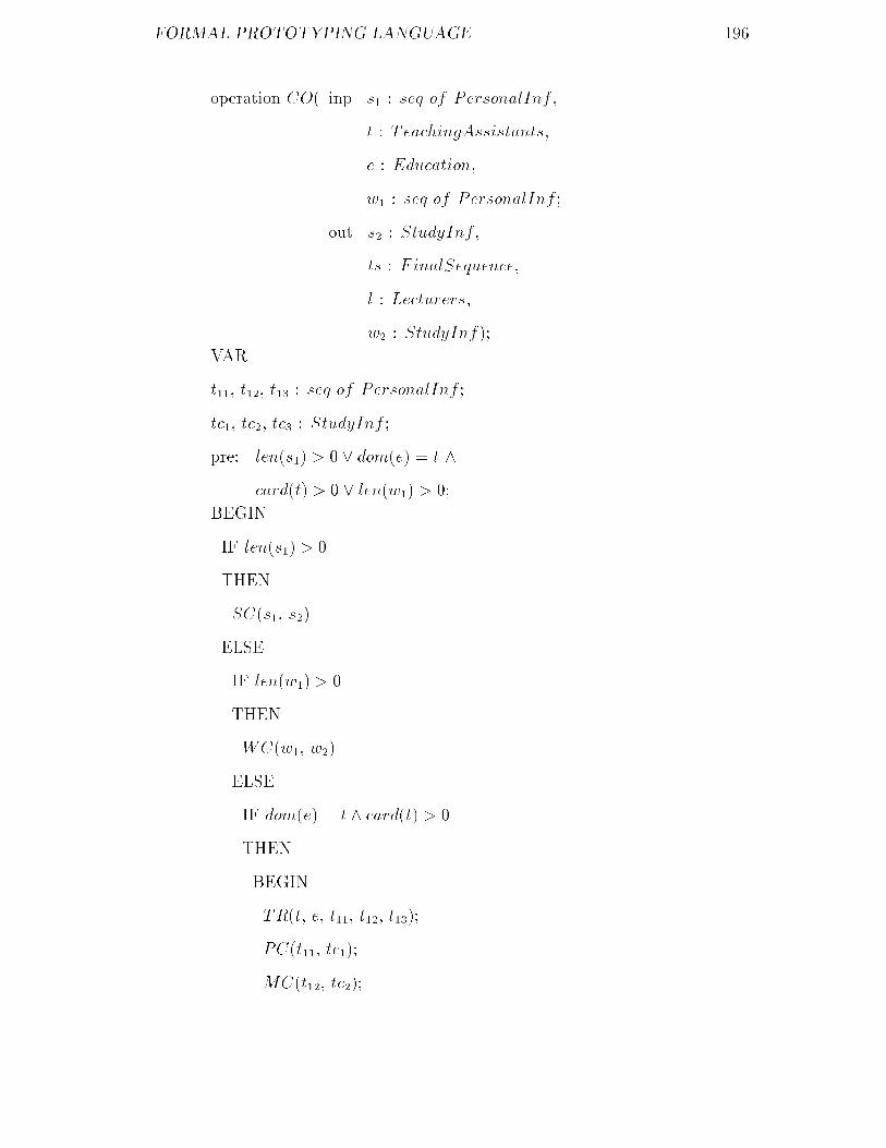
FORMAL PROTOTYPING LANGUAGE ���
operation CO� inp s� � seq of PersonalInf
t � TeachingAssistants
e � Education
w� � seq of PersonalInf �
out s� � StudyInf
ts � FinalSequence
l � Lecturers
w� � StudyInf��
VAR
t�� t�� t�� � seq of PersonalInf �
tc� tc� tc� � StudyInf �
pre� len�s�� � � dom�e� � t �
card�t� � � len�w�� � ��
BEGIN
IF len�s�� � �
THEN
SC�s� s��
ELSE
IF len�w�� � �
THEN
WC�w� w��
ELSE
IF dom�e� � t � card�t� � �
THEN
BEGIN
TR�t e t�� t�� t����
PC�t�� tc���
MC�t�� tc���

FORMAL PROTOTYPING LANGUAGE ��
BC�t�� tc���
TS�tc� tc� tc� ts l�
END�
Note that in this implementation of the condition process CO we realize the
availability of the input data �ex� s�� in the speci�cation by testing whether the
corresponding input arguments �ex� s�� of the corresponding operation �ex� CO�
satisfy the corresponding sub�pre�condition �ex� len�s�� � �� and realize the
corresponding functionality of producing available output data expressed in the
speci�cation by using the conditional statement IF�THEN�ELSE� The �ring of
the condition process in the speci�cation SC for example is realized by calling
the corresponding operation SC�s� s�� in the implementation�
operation SC� inp s� � seq of PersonalInf �
out s� � StudyInf��
VAR
i mark � INTEGER�
pre� len�s�� � ��
BEGIN
i �� ��
WHILE i � len�s�� DO
BEGIN
WHILE mark � � mark � ��� DO
INPUT�mark��
s��s��i�� �� mark�
i �� i� �
END
END�
This non�terminal operation is the implementation of the condition process
SC in the speci�cation�

FORMAL PROTOTYPING LANGUAGE ��
operation WC� inp w� � seq of PersonalInf �
out w� � StudyInf��
VAR
i mark � INTEGER�
pre� len�w�� � ��
BEGIN
i �� ��
WHILE i � len�w�� DO
BEGIN
WHILE mark � � mark � ��� DO
INPUT�mark��
w��w��i�� �� mark�
i �� i� �
END
END�
This non�terminal operation is the implementation of the condition process
WC in the speci�cation�
operation TR� inp t � TeachingAssistants
e � Education�
out t�� t�� t�� � seq of PersonalInf��
pre� dom�e� � t � card�t� � ��
post� elem�t��� � fx � t j e�x� � �Ph�D�g �
elem�t��� � fx � t j e�x� � �M�Sc�g �
elem�t��� � fx � t j e�x� � �B�Sc�g �
card�t� � len�t��� � len�t��� � len�t����
The condition process TR in the speci�cation is implemented by this terminal
operation� This can be done due to the simplicity of the post�condition of TR in
the speci�cation�

FORMAL PROTOTYPING LANGUAGE ���
�� Discussion on FPL
The formal language FPL provides a more powerful mechanism than current high
level languages �Pascal C COBOL FORTRAN etc� for prototype construction
from FGSL speci�cations� Since the concepts of pre�conditions for non�terminal
operations as well as pre� and post�conditions for terminal operations are em�
ployed the implementation of a prototype system using FPL can focus on the
representation of the functionality of the system and the proof of its correctness
against its FGSL speci�cation� Proof of an FPL program against its FGSL spe�
ci�cation is much easier than for other high level languages because FPL and
FGSL use similar notation�
However the results embodided in FPL are only a small step �but very im�
portant step� in attacking the real problem� Some other issues which need to be
dealt with are concurrent execution of multiple threads and separate compilation
of modules� Human computer interfaces are also critical problems for prototypes
and �nal products� Further work on FPL is therefore required to develop more
control structures and more mechanisms to cope with these more complicated
issues�

Part IV Summary
���

Chapter �
Conclusions
This dissertation introduces the structured and formal method SFRAM for re�
quirements analysis� It consists of two stages� static and dynamic requirements
analysis� A language for each stage is provided� The result of the �rst stage is
a requirement speci�cation expressed by the language FGSL and the result of
the second stage is a prototype program �and the prototype system� written in
FPL produced based on the corresponding FGSL speci�cation� This program
may be proved with the provided axiom and rules of inference to satisfy its FGSL
speci�cation�
The FGSL is created by combining �and extending� the model of DeMarco
data �ow diagrams with the mathematical notation used in VDM� A FGSL spe�
ci�cation is constructed by using the method FGSM� It consists of the three steps�
Model Real World Data Analysis and Specify Functionality� Each step enriches
the result produced at the previous step and might cause the modi�cation of the
previous result� Corresponding consistency must be checked at each step for en�
suring the quality of the �nal FGSL speci�cations� Speci�cations produced using
this method are both comprehensible to users �to a certain degree� and precise
in semantics and can be the �rm basis for rapid prototyping and �nal system
production�
���

CONCLUSIONS ���
The FPL is designed by combining �and extending� Pascal�like languages with
the mathematical notation used in VDM �also in FGSL�� It adopts almost the
same abstract data types and their associated operations as in VDM for declar�
ing variables� It also employs the structure pre� and post�conditions with some
constraints for expressing operations and functions� Upper level �non�terminal�
operations are constructed using the sequential conditional and iteration state�
ments� Furthermore FPL relaxes constraints on the program structure and types
of parameters of operations compared with Pascal�like languages �such as Pascal
C etc�� which could facilitate programming� Constructing prototype programs
using FPL based on their FGSL speci�cations and Proving FPL programs against
their FGSL speci�cations are much easier than for other high level languages�
In this chapter we will give the comparsion of the method SFRAM with the
related informal and formal methods for requirements analysis and speci�cations
construction after summarizing the speci�c contributions achieved in this disser�
tation� After that the further research will be pointed out�
��� Contributions
In detail this dissertation has achieved the original progress in the area of re�
quirements analysis methodology in the following aspects�
�� Propose the structured and formal method SFRAM for requirements ana�
lysis based on data �ow analysis and rapid prototyping� It emphasizes not
only the importance and necessity of using formal notation in static require�
ments analysis to achieve formal speci�cations but also the importance and
necessity of rapid prototyping in dynamic requirements analysis to achieve a
prototype for assisting clients to discover more requirements and to con�rm
�and modify� the produced static requirements speci�cations� The eventual

CONCLUSIONS ���
result of requirements analysis is both a modi�ed formal requirements spe�
ci�cation and a modi�ed prototype program �and system� from SFRAM
point of view�
�� Create the structured formal language FGSL for expressing requirements
speci�cations by combining �and extending� the model of DeMarco data
�ow diagrams with the mathematical notation used in VDM� The abstract
syntax and formal semantics of FGSL are described� Based on this language
the formal graphic speci�cation method FGSM for constructing FGSL spe�
ci�cations in the stage of static requirements analysis is described�
�� Propose the concept of model consistency analysis for ensuring that the
model of hierarchical condition data �ow diagrams in FGSL is semantic�
ally consistent with respect to data availability� This consistency includes
the four aspects� global consistency structural consistency condition con�
sistency and diagrammatical consistency� The corresponding method for
checking each aspect of this consistency is presented�
�� Propose the concept of internal consistency analysis for ensuring that the
model of hierarchical condition data �ow diagrams is semantically consist�
ent with respect to the functionality of condition processes expressed by
pre� and post�conditions� To guarantee the internal consistency for the
decomposition of a condition process into its decomposed condition data
�ow diagram it is necessary to check and ensure the Pre�Avl consistency
Pre�Post consistency and successor Post�Pre consistency for every condition
process in the decomposed CDFD� The corresponding methods for checking
each consistency metioned here are described�
�� The application and the philosophy of the method FGSM are demonstrated
by a reasonably large example� The limitation of the application of FGSM

CONCLUSIONS ���
is discussed in detail�
�� Design the formal language FPL for rapid prototyping� Prototype programs
are constructed in the stage of dynamic requirements analysis based on the
corresponding FGSL speci�cations� The produced programs may be proved
to satisfy the FGSL speci�cations�
� The axiom and rules of inferences for correctness proofs of FPL programs
against their FGSL speci�cations are described� A proposal of an approach
of transforming a FGSL speci�cation into a FPL program is discussed and
demonstrated by an example�
��� Comparsion
First of all the philosophy of the requirements analysis method SFRAM is more
advanced than those of existing informal and formal methods for requirements
analysis in general� The existing informal methods can only be used to achieve
abstract informal requirements and rapid prototyping technology based on in�
formal requirements speci�cations are not powerful enough to portray function�
ality �Connell ��� The existing formal methods advocate that it is necessary
to introduce the mathematical notation for constructing speci�cations and the
further development of systems will completely base on the produced formal spe�
ci�cations �e�g� VDM�� While the SFRAM advocates the use of the combination
of graphic notation formal notation and rapid prototyping for requirements ana�
lysis� The graphic notation is comprehensible to clients� The formal notation
is for achieving the precise semantics of the graphic notation and the precise
functional speci�cations� The rapid prototyping which must be based on the
produced static formal speci�cations is for assisting clients to discover more re�
quirements for the dynamic behaviour or properties of the proposed systems and

CONCLUSIONS ���
to con�rm �even modify or enrich� the static formal speci�cations�
The comparsion of SFRAM with the related speci�c informal and formal
methods are illustrated as follows�
�� Comparsion of SFRAM with DeMarco�s approach�
As described in the chapter � DeMarco�s approach is to use data �ow dia�
grams and data dictionary together to describe requirements speci�cations�
But each of these two lacks formality and therefore cannot provide precise
information for further development of systems� The FGSM in SFRAM
overcomes this weakness of DeMarco�s approach� The hierarchical con�
dition data �ow diagram in a FGSL speci�cation re�ects the functional
requirements precisely� The types and type invariants in the FGSL speci�c�
ations describe the structures and the proterties of all the data to be used
which is more precise than de�nitions of data �ows in the data dictionary
in DeMarco�s approach� A whole FGSL speci�cation is well structured�
�� Comparsion of SFRAM with VDM�
In VDM speci�cations are constructed around abstract states which are
models de�ned in terms of data objects such as sets maps and lists� Oper�
ations on these state�like objects are speci�ed by pre� and post�conditions�
The e�ect of the execution of an operation is the change of the state from
initial state to �nal state� Operations are constructed into a speci�cation
by the sequential conditional and iterative combinators� SFRAM is more
powerful and practical than VDM in three aspects� The static requirements
speci�cations are constructed hierarchically based on decomposition of con�
dition processes and data �ow analysis which is more comprehensible to
clients than based on the combinators and state change� The concurrent
execution can be expressed by parallel structure which cannot be realized

CONCLUSIONS ���
in VDM� The dynamic requirements analysis by means of rapid prototyp�
ing is an advantage over VDM as it could help clients and developers break
through the obstacle in communication via formal speci�cations to obtain
true requirements�
��� Further Research
Although the results embodied in SFRAM has made original progress in the
area of requirements analysis methodology further research is required to develop
SFRAM into a more powerful method suitable for more applications� Speci�cally
further work should be done in the following aspects�
�� Introduce more abstract data types to FGSL�
It is di�cult to express the true requirements for the interfaces of proposed
systems by using FGSL in the stage of static requirements analysis� This
is because the interfaces are often concerned with graphic notation such as
circles ovals lines and triangle etc� The requirements for interfaces are
especially important for commercial systems and safety critical systems�
Furthermore a tree structure and graph structure objects are often well
known in the real world of some application areas� In FGSL these objects
have to be represented by combination of sequence map and sets objects
etc� This will increase the di�culity in communication between clients
and developers� Therefore it is very useful to introduce more abstract
data types for de�ning and operating graphic objects and more complicated
objects�
�� Introduce the concept of time to FGSL�
As described in the last section of chapter � there is no way available in
FGSL for specifying the time requirements for �ring of condition processes�

CONCLUSIONS ��
Therefore it is very di�cult �if possible� to express functional requirements
for real time systems using FGSL� To make FGSL suitable for specifying
functional requirements for real time systems it is necessary to introduce
the concept of time to FGSL� This is a very important research topic�
�� Extend FGSL to be suitable for concurrent systems�
How to specify the functional requirements for concurrent systems is also a
very important research �eld� FGSL at present can be used to express the
concurrent execution by parallel structure but does not have any mechan�
ism available for communication between two condition processes which are
being executed concurrently� If such a mechanism is introduced into FGSL
the semantics of FGSL and consistency within a speci�cation needs to be
investigated�
�� Design more control structures and mechanisms for FPL�
As described in the last section of chapter the results embodied in FPL
are only a small step in attacking the real problem although they are very
important� Some other issues which need to be dealt with are concur�
rent execution of multiple threads and separate compilation of modules�
Human computer interfaces are also critical problems for prototypes and
�nal products� Further work on FPL is therefore required to develop more
control structures �e�g� REPEAT statement FOR statement and CASE
statement in Pascal� and more mechanisms �e�g� concurrency and generic
operations etc� to cope with the more complicated issues�
�� Develop a requirements analysis environment based on SFRAM�
To support the use of SFRAM it is necessary to develop a requirements
analysis environment based on SFRAM� This environment should include
two tool packages� The �rst one is for supporting FGSM and the second is

CONCLUSIONS ��
for supporting rapid prototyping using FPL� The �rst tool package should
include tools to support the three steps in FGSM� Model Real World Data
Analysis and Specify functionality� The second one should include a com�
piler of FPL correctness proof assisting system and prototype construction
assisting system�

Appendix A
Glossary of Symbols
The symbols used in this dissertation are similar to those used in VDM �Jones
�� though there are some di�erences�
Numbers
N� � f� � ���g
N � f� � � ���g
Z � f��� �� � � ���g
R � real numbers
char � characters
Functions
f � D� �D� �� R signature
f�d� application
if ��� then ��� else ��� conditional
let x � ��� in ��� local de�nition
Logic
B � ftrue falseg
All the logical operators are from �Jones ��
Sets
���
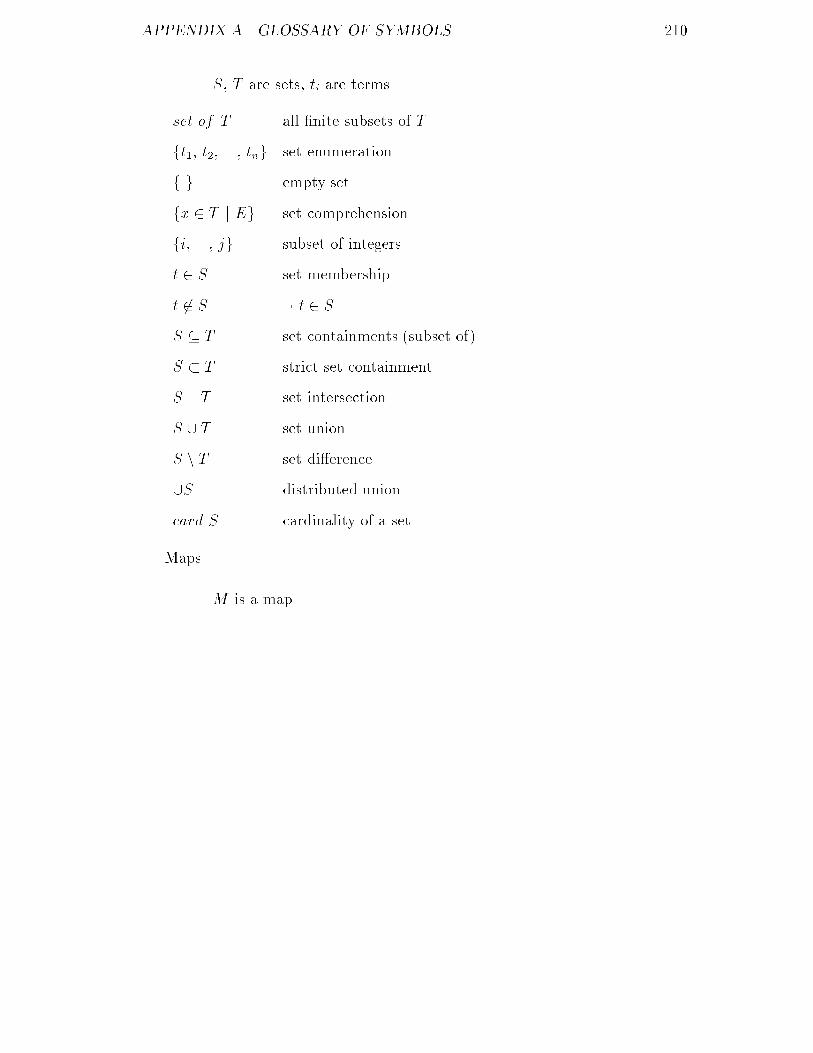
APPENDIX A� GLOSSARY OF SYMBOLS ���
S T are sets ti are terms
set of T all �nite subsets of T
ft� t� ��� tng set enumeration
f g empty set
fx � T j Eg set comprehension
fi ��� jg subset of integers
t � S set membership
t �� S � t � S
S � T set containments �subset of�
S T strict set containment
S � T set intersection
S � T set union
S n T set di�erence
�S distributed union
card S cardinality of a set
Maps
M is a map

APPENDIX A� GLOSSARY OF SYMBOLS ���
map D to R �nite maps
dom M domain
rng M range
fd� �� r� d� �� r� ��� dn �� rng map enumeration
f g empty map
fd �� f�d� j Eg map comprehension
m�d� application
S �M domain restriction
S �M domain deletion
M� yM� overwriting
Sequences
s t are sequences
seq of T �nite sequence
len s length
�t� t� ��� tn� sequence enumeration
� � empty sequence
con�t� t� ��� tn� sequence generator
con s generator
s� t concatenation
hd s head
tl s tail
s�i� ���� j� sub�sequence
Composite Objects
o is a composite object

APPENDIX A� GLOSSARY OF SYMBOLS ���
compose N of ��� end
where inv�N�� � ��� invariant
nil omitted object
m�N�� generator
s��o� selector
��o� s� �� t� modify a component
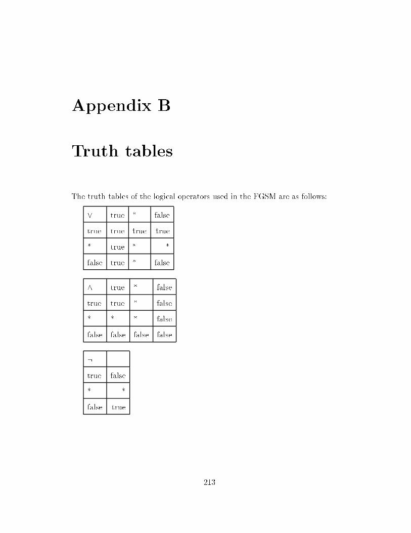
Appendix B
Truth tables
The truth tables of the logical operators used in the FGSM are as follows�
true � false
true true true true
� true � �
false true � false
� true � false
true true � false
� � � false
false false false false
�
true false
� �
false true
���

APPENDIX B� TRUTH TABLES ���
�� true � false
true true � false
� true � �
false true true true
�� true � false
true true � false
� � � �
false false � true
� true false
true false true
false true false

Bibliography
�Abrial �� J��R� Abrial �A Formal Approach to Large Software Construction� in
Mathematics of Program Construction �ed� J�L�A�van de Snepscheut�� Springer�
Verlag ����
�Abrial ��� J��R� Abrial et al �The B Method� in VDM��� Formal Software
Development Methods �ed� S� Prehen and W�J� Toetenel�� Springer�Verlag �����
pp� �������
�Adler � Mike Adler �An Algebra for Data Flow Diagram Process Decompos�
ition� IEEE Transactions On Software Engineering Vol� �� No� � February
���
�Ah�Kee �� J�A� Ah�Kee �Operation Decomposition Proof Obligations for Blocks
and Procedures� Ph�D thesis University of Manchester ����
�Barden ��� R� Barden et al� �The Use of Z� The Proceedings of Sixth Annual
Z User Meeting University of York pp� ���� �����
�Bear � S� Bear �Structuring for the VDM Speci�cation Language� VDM�
Lecture Notes in Computer Science Springer�Verlag Berlin Heidelberg pp� ����
���
�Beck �� L�L� Beck and T�E� Perkins �A survey of software engineering practice�
���

BIBLIOGRAPHY ���
tools methods and results� IEEE Transaction on Software Engineering SE�� ���
pp� ������� ����
�Bird � Richard Bird Philip Wadler �Introduction to Functional Program�
ming� Prentice�Hall International�UK� Ltd� ���
�Bj�rner � D� Bj�rner �Programming in The Meta�Language� A Tutorial�
Lecture Notes in Computer Science �� Springer�Verlag Berlin Heidelberg pp�
����� ���
�Bj�rner �� D� Bj�rner and C�B� Jones �Fromal Speci�cation and Software
Development� Prentice�Hall International Inc� ����
�Bj�rner �� D� Bj�rner et al� �The RAISE Project � Fundamental Issues and
Requirements� RAISE�DDC�EM�� Dansk Datamatik Center ����
�Bj�rner � D� Bj�rner �The Stepwise Development of Software Development
Graphs ! Meta�Programming VDM Development� VDM� Lecture Notes in
Computer Science ��� Springer�Verlag Berlin Heidelberg pp� ��� ���
�Boar �� B� Boar �Application Prototyping� A Requirements De�nition Strategy
for the �s� New York� John Wiley and Sons ����
�Booch �� G� Booch �Software Engineering with Ada� The Benjamin�Cummings
Publishing Company Inc� ����
�Brass �� B�F� Brass etal� �An Instrument for Program Transformation and Rule
Generation� Technical University of Munich Report I��� ����
�Burstall � R�M� Burstall and J� Darlington �A Transformation System for
Developing Recursive Programs� Journal ACM �� January ���

BIBLIOGRAPHY ��
�Caneghem �� M�V� Caneghem and D�H�D� Warren �Logic Programming and
Its Applications� Ablex Publishing Corporation ����
�Chen �� B�S� Chen and R�T� Yeh �Formal Speci�cation and Veri�cation of
Distributed Systems� IEEE Transactions on Software Engineering Vol� SE��
NO� � pp ����� November ����
�Connell �� John L� Connell Linda Brice Shafer �Structured Rapid Prototyping
� An Evolutionary Approach to Software Development� Yourdon Press comput�
ing series Prentice�Hall Inc� ����
�Crispin � R�J�Crispin �Experience Using VDM In STC� Lecture notes in
Computer Science� ��� Springer�Verlag Berlin Heidelberg pp ����� ���
�DeMarco � Tom DeMarco �Structured Analysis and System Speci�cation�
Yourdon Inc� New York ���
�Dijkstra �� E�W� Dijkstra �A discipline of Programming� series in Automatic
Computation Prentice�Hall ����
�Downs � Ed Downs and P� Clare etc� �Structured Systems Analysis and Design
Method� Prentice Hall International�UK� Ltd ���
�Duce � D�A� Duce and E�V�C� Fielding �Formal Speci�cation � A Comparison
of Two Techniques� The Computer Journal Vol� �� No� � pp ������ ���
�Duce � D�A� Duce and E�V�C� Fielding �Formal Speci�cation of A Small Ex�
ample based on GKS� ACM Trans� Graphics Vol� pp� ����� ���
�Ehrig � H� Ehrig H�J� Kreowski and P� Padawitz �Stepwise Speci�cation and
Implementation of Abstract Data Types� Automata Languages and Program�
ming Lecture Notes in Computer Science �� Springer�Verlag Berlin Heidelberg

BIBLIOGRAPHY ��
pp ������� ���
�Ehrig �� H� Ehrig and B� Mahr �Fundamentals of Algebraic Sepeci�cation ��
Springer�verlag Berlin Heidelberg ����
�Fraser ��� M�D� Fraser et al �Informal and Formal Requirements Speci�cation
Languages � Bridging the Gap� IEEE Transactions on Software Engineering
Vol� � No� � May ����� pp ��������
�Gane �� C� Gane and T� Sarson �Structured Systems Analysis� Tools and
Techniques�� Prentice�Hall Englewood Cli�s New Jersey ����
�Gordon �� M�J�C� Gordon �The Denotational Description of Programming Lan�
guages� Springer�Verlag New York Inc� ����
�Goguen �� J�A� Goguen and J�J� Tardo �An Introduction to OBJ� a language for
writing and testing formal algebraic program speci�cations� Proceedings IEEE
Conference on Speci�cation for Reliable Software IEEE Computer Society pp
����� ����
�Gries �� D� Gries �The Science of Computer Programming� Springer�Verlag
����
�Handerson �� Peter Handerson �Functional Programming� Prentice�Hall In�
ternational INC� London ����
�Hayes �� Ian J� Hayes �Applying Formal Speci�cation to Software Development
in Industry� IEEE Transactions on Software Engineering� Vol� SE��� No� �
pp� ����� February ����
�Hehner �� E� Hehner �The Logic of Programming� Prentice�Hall International
����

BIBLIOGRAPHY ���
�Hoare �� C�A�R� Hoare and N� Wirth �An Axiomatic De�nition of the Program�
ming Language PASCAL� Acta Informatica Springer�Verlag Berlin pp �������
����
�Hoare �� C�A�R� Hoare �Communicating Sequential Processes� Prentice�Hall
International UK LTD� ����
�Hogger �� C�J� Hogger �Introduction to Logic Programming� Academic Press
Inc� �London� Ltd� ����
�Jackson �� M�A� Jackson �Principles of Program Design� Academic Press INC�
�London� LTD� ����
�Jackson �� Michael Jackson �System Development� Prentice�Hall Interna�
tional INC� U�S�A� ����
�Jones � C�B� Jones �The Meta�Language� A Reference Manual� Lecture
Notes in Computer Science �� Springer�Verlag Berlin Heidelberg pp� ����
���
�Jones �� C�B� Jones �Software Development� Prentice�Hall International�London�
Inc� ����
�Jones �� C�B�Jones �Speci�cation Veri�cation and Testing in Software Devel�
opment� Software Requirement Speci�cation and Testing Blackwell Scienti�c
Publication Editorial O�ces U�K� pp ���� ����
�Jones �� C�B� Jones �Systematic Software Development Using VDM� Prentice�
Hall International�UK� Ltd ����
�Jones a� K�D� Jones �Support Environments for VDM� VDM� Lecture
Notes in Computer Science ��� Springer�Verlag Berlin Heidelberg pp� ������
BIBLIOGRAPHY ���
���
�Jones b�C�B� Jones �VDM Proof Obligations and their Justi�cation� VDM�
Lecture Notes in Computer Science ��� Springer�Verlag Berlin Heidelberg pp�
������ ���
�Jones ��� C�B� Jones �Case Studies in Systematic Software Development�
Prentice�Hall International�UK� Ltd� pp ������ �����
�King ��� S� King �Z and the Re�nement Calculus� VDM��� Lecture Notes in
Computer Science Springer�Verlag Berlin Heidelberg pp� ����� �����
�Kr��oger � F� Kr
��oger �Temporal Logic of Programs� Springer�Verlag Berlin
Heidelberg ���
�Latham �� John T� Latham �Abstract Pascal Reference Manual� Reference
Manual University of Manchester ����
�Latham ��� John T� Latham �The Programming Process � An Introduction
Using VDM and Pascal� Addison�Wesley Publishers Ltd� �����
�Leveson �� Nancy G� Leveson �Software Safety� Why What and How� Com�
puting Surveys Vol� � No� � June ����
�Li �� Youren Li and Shaoying Liu �Design and Implementation of COBOL
program Testing System CPTS!�� Proceedings of The International Workshop
on Software Engineering Environment Beijing ���� August ����
�Li � Youren Li and Shaoying Liu et al �Research of Transformation Tool From
Program To Two Degree Logical Diagrams� Journal of Xi�an Jiaotong University
Vol� �� Sup� No�� ��
BIBLIOGRAPHY ���
�Li �� Youren Li and Shaoying Liu �Implementation of COBOL Program Testing
Envirmonent� Journal of Xi�an Jiaotong University Vol��� No�� ���
�Liskov et al �� B� Liskov and J� Guttag �Abstraction and Speci�cation in
Program Development� The MIT Press McGraw�Hill Book Company ����
�Liu a� Shaoying Liu and Youren Li �Production Software Development Doc�
ument� Computer Techanique Information No� � China ���
�Liu b� Shaoying Liu and Youren Li �A Kind of Automatic Test Data Gener�
ation Method� Computer Engineering China No�� ��
�Liu ��a� Shaoying Liu and Youren Li �Production Software Development Tool�
Computer Research and Development No� � Beijing �����
�Liu ��b� Shaoying Liu �Formal Software Development Technology� Computer
Science China No� � pp� ��� �� �����
�Liu ��c� Shaoying Liu �Gradually Formal System Development Method� Pro�
ceedings of the International Conference on Systems Management ��� Hong
Kong PP� ����� ����� June �����
�Liu ��� Shaoying Liu �A Practical Method for Producing Precise Requirements
Speci�cations � Proceedings of Second Great Lakes Computer Science Confer�
ence Kalamazoo MI USA October ���� �����
�Liu ��a� Shaoying Liu �A Formal Software Design Language and Correctness
Proofs� Proceedings of Nordic Workshop on Programming Environment Re�
search Tampere Finland ��� January �����
�Liu ��b� Shaoying Liu �A Formal Structured Method for Requirement Speci�ca�
tion Construction� Proceedings of ���� ACM Symposium on Applied Computing

BIBLIOGRAPHY ���
�SAC ���� Kansas City USA ��� March �����
�Liu ��c� Shaoying Liu �A Formal Graphic Language for Requirements Speci�c�
ation of Information Systems� Proceedings of �nd Irvine Software Symposium
�ISS���� Irvine USA � March �����
�Liu ��d� Shaoying Liu �A User�Friendly Formal Requirements Speci�cation
Method� Proceedings of ��th Annual ACM Southeast Conference Raleigh NC
USA ��� April �����
�Liu ��e� Shaoying Liu �An Abstract Programming Language and Correctness
Proofs� Computer Languages � An International Journal Vol� � No� � �����
�Liu ��� Shaoying Liu �A Formal Requirements Speci�cation Method Based on
Data Flow Analysis� The Journal of Systems and Software �to be published��
�Lucas � Peter Lucas �VDM� Origins Hopes and Achievements� VDM�
VDM�A Formal Method at Work Lecture Notes in Computer Science pp ���
���
�Manna �� Z� Manna and R� Waldinger �Synthesis� Dreams � Programs� IEEE
Transactions on Software Engineering SE����� July ����
�McDermid ��a� John A McDermid and Shaoying Liu �A Formalisation of Ar�
gument Structure for SAM� ASAM Project Report January �����
�McDermid ��b� John A McDermid and Shaoying Liu �A Speci�cation of Fault
Tree for SAM� ASAM Project Report March �����
�Mendelson � E� Mendelson �Introduction to Mathematical Logic� Wadworth
and Brook�Cole Third Edition ���

BIBLIOGRAPHY ���
�Methlie �� L�B� Methlie �System Requirements Analysis!Methods and Mod�
els� in the Information Systems Environment H�C� Lucas et al Eds� Amster�
dam The Netherlands� North�Holland ����
�Minkowitz � C� Minkowitz and P� Henderson �A Formal Description of Object�
Oriented Programming Using VDM� VDM� Lecture Notes in Computer Sci�
ence ��� Springer�Verlag Berlin Heidelberg pp� ������ ���
�Milne � R� Milne �Proof Rules for VDM Statements� VDM� Lecture Notes
in Computer Science �� Springer�Verlag Berlin Heidelberg pp� ������ ���
�Morgan ��� C� Morgan �Programming from Speci�cations� Prentice�Hall In�
ternational�UK� Ltd� �����
�Naftalin � M� Naftalin �Correctness for Beginners� VDM � The Way Ahead
Lecture Notes in Computer Science �� Springer�Verlag Berlin Heidelberg pp
��� ���
�Nielsen � M� Nielsen K� Havelund et al �The RAISE Language Method and
Tools� VDM� Lecture Notes in Computer Science �� Springer�Verlag Berlin
Heidelberg pp� ������ ���
�Partsch �� Partsch and Steinbruggen �Program Transformation Systems� ACM
Computer Surveys ����� September ����
�Pedersen � J�S�Pedersen and M�H�Klein �Using the Vienna Development Method
�VDM� to Formalize A Communications Protocol�� Software Eng� Res� Inst�
Carnegie Mellon University Pittsburgh PA Tech� Rep� CMU�SEI��TR���
ESD�TR���� ���

BIBLIOGRAPHY ���
�Pomberger �� G� Pomberger �Software Engineering and Modula��� Prentice�
Hall International Series in Computer Science ����
�Prehn � S� Prehn �From VDM to RAISE� VDM! A Formal Method at Work
Lecture Notes in Computer Science ��� Springer�Verlag Berlin Heidelberg pp
������� March ���
�Randell ��� Gill Randell �Data Flow Diagrams and Z� Proceedings of the Z
User Group ���� Springer�Verlag �����
�Reynolds �� J�C� Reynolds �The Craft of Programming� Prentice�Hall Inter�
national ����
�Schmidt � U� Schmidt and R� Voller �Experience with VDM on Norsk Data�
in Lecture Notes in Computer Science ���� VDM� VDM�A Formal Method at
Work D� Bjorner CB� Jones M�Mac an Airchinnigh and E� Neuhold Eds� New
York� Springer�Verlag pp� ����� ���
�Schwartz �� J�T� Schwartz �A Comment on Correctness Proofs� SETL News�
letter ��� Courant Inst� of Math� N�Y�Univ� pp� ���� ����
�Schwartz �� J�T� Schwartz and R�B�K� Dewar et al� �Programming with SETS
An Introduction to SETL� Springer�verlag New York Inc� ����
�Semmens ��� L� Semmens and P� Allen �Using Yourdan and Z � an Approach
to Formal Speci�cation� Proceedings of the Z User Group ���� Springer�Verlag
�����
�Shemer � I� Shemer �Systems Analysis� A Systematic Analysis of a Conceptual
Model� Commun� ACM Vol� �� No� � pp� ������� June ���
�Spivey � J�M� Spivey �Understanding Z� a speci�cation language and its formal

BIBLIOGRAPHY ���
semantics� Number � in Cambridge Tracts in Theoretical Computer Science�
Cambridge University Press Cambridge ���
�Spivey �� J�M� Spivey �The Z Notation� Prentice Hall International �UK� Ltd�
����
�Steward � D�V� Steward �Software Engineering with Systems Analysis and
Design� Wadsworth Inc� Belmont California ����� pp ����� ���
�Tao ��� Y� Tao and C� Hung �Formal De�nition and Veri�cation of Data Flow
Diagrams� Journal of Systems and Software pp� ����� �����
�Tremblay �� J�P� Tremblay and P�G� Sorenson �An Introduction to Data Struc�
tures with Applications� McGraw�Hill New York ����
�Tse �� T�H�Tse and L� Pong �Towards a Formal Foundation for DeMarco Data
Flow Diagrams� The Computer Journal Vol� �� No� � pp ���� ����
�Turski � W�M� Turski �The Speci�cation of Computer Programs� Addison�
Wesley Publishing Company Inc� ���
�Weinberg �� V� Weinberg �Structured Analysis�� Prentice�Hall Englewood
Cli�s New Jersey ����
�Welsh �� J� Welsh and J� Elder �Introduction to PASCAL� Prentice�Hall In�
ternational�London� Inc� ����
�Wikstr��om �
o
A� Wikstr��om �Functional Programming Using Standard ML�
Prentice Hall International�UK� Ltd ���