A review on design criteria for vortex tubes - Amazon Web … · ir irreversible s isentropic 1...
20
ORIGINAL A review on design criteria for vortex tubes M. Yilmaz Æ M. Kaya Æ S. Karagoz Æ S. Erdogan Received: 27 March 2008 / Accepted: 18 September 2008 / Published online: 16 October 2008 Ó Springer-Verlag 2008 Abstract In this study, the past investigations of the design criteria of vortex tubes were overviewed and the detailed information was presented on the design of them. Vortex tubes were classified and the type of them was described. All criteria on the design of vortex tubes were given in detail using experimental and theoretical results from the past until now. Finally, the criteria on the design of them are summarized. List of symbols A cross section (m 2 ) CFD computational fluid dynamics COP coefficient of performance c p specific heat at constant pressure (kJ kg -1 K -1 ) c v specific heat at constant volume (kJ kg -1 K -1 ) d diameter (m) D diameter (m) h enthalpy (kJ kg -1 ) k specific heat ratio k Boltzmann constant (J K -1 ) L length (m) _ m mass flow rate (kg s -1 ) N number p pressure (Pa) _ Q heat transfer rate (W) R specific gas constant (kJ kg -1 K -1 ) RHVT Ranque–Hilsch vortex tube S entropy (W K -1 ) T temperature (K) T sm temperature assumed to be T 1e h T e c _ W power (W) X normalised pressure drop X ¼ p in p c ð Þ=p in ð Þ Greek symbols a angle of cone-shaped control valve a ratio of hot end area to tube area b cold orifice diameter ratio b ¼ d c =D ð Þ e cold fraction e o Lennard–Jones potential g efficiency DT temperature difference DT =T in normalised temperature drop/rise C k 1 ð Þ=k H irreversibility parameter s p pressure ratio ¼ p in =p c ð Þ Subscripts atm atmosphere c cold cr cooler cr critical h hot hp heat pump in inlet i irreversible M. Yilmaz (&) S. Karagoz Department of Mechanical Engineering, Engineering Faculty, Atatu ¨rk University, Erzurum, Turkey e-mail: [email protected] S. Karagoz e-mail: [email protected] M. Kaya Tu ¨rk Hava Yolları Teknik A. S ¸ . Havaalanı, Erzurum, Turkey e-mail: [email protected] S. Erdogan Erzurum Vocational School of Higher Education, Atatu ¨rk University, Erzurum, Turkey e-mail: [email protected] 123 Heat Mass Transfer (2009) 45:613–632 DOI 10.1007/s00231-008-0447-8
Transcript of A review on design criteria for vortex tubes - Amazon Web … · ir irreversible s isentropic 1...
ORIGINAL
A review on design criteria for vortex tubes
M. Yilmaz Æ M. Kaya Æ S. Karagoz ÆS. Erdogan
Received: 27 March 2008 / Accepted: 18 September 2008 / Published online: 16 October 2008
� Springer-Verlag 2008
Abstract In this study, the past investigations of the
design criteria of vortex tubes were overviewed and the
detailed information was presented on the design of them.
Vortex tubes were classified and the type of them was
described. All criteria on the design of vortex tubes were
given in detail using experimental and theoretical results
from the past until now. Finally, the criteria on the design
of them are summarized.
List of symbols
A cross section (m2)
CFD computational fluid dynamics
COP coefficient of performance
cp specific heat at constant pressure (kJ kg-1 K-1)
cv specific heat at constant volume (kJ kg-1 K-1)
d diameter (m)
D diameter (m)
h enthalpy (kJ kg-1)
k specific heat ratio
k Boltzmann constant (J K-1)
L length (m)
_m mass flow rate (kg s-1)
N number
p pressure (Pa)_Q heat transfer rate (W)
R specific gas constant (kJ kg-1 K-1)
RHVT Ranque–Hilsch vortex tube
S entropy (W K-1)
T temperature (K)
T�sm temperature assumed to be T1�eh Te
c_W power (W)
X normalised pressure drop X ¼ pin � pcð Þ=pinð Þ
Greek symbols
a angle of cone-shaped control valve
a ratio of hot end area to tube area
b cold orifice diameter ratio b ¼ dc=Dð Þe cold fraction
eo Lennard–Jones potential
g efficiency
DT temperature difference
DT=Tin normalised temperature drop/rise
C k � 1ð Þ=k
H irreversibility parameter
sp pressure ratio ¼ pin=pcð Þ
Subscripts
atm atmosphere
c cold
cr cooler
cr critical
h hot
hp heat pump
in inlet
i irreversible
M. Yilmaz (&) � S. Karagoz
Department of Mechanical Engineering, Engineering Faculty,
Ataturk University, Erzurum, Turkey
e-mail: [email protected]
S. Karagoz
e-mail: [email protected]
M. Kaya
Turk Hava Yolları Teknik A. S. Havaalanı, Erzurum, Turkey
e-mail: [email protected]
S. Erdogan
Erzurum Vocational School of Higher Education,
Ataturk University, Erzurum, Turkey
e-mail: [email protected]
123
Heat Mass Transfer (2009) 45:613–632
DOI 10.1007/s00231-008-0447-8
ir irreversible
s isentropic
1 Introduction
The vortex tube is a device without moving mechanical
parts, which converts a gas flow initially homogeneous in
temperature, into two separate flows of differing tempera-
tures. It separates compressed gas stream into a low total
temperature region and a high one. Such a separation of the
flow into regions of low and high total temperature is
referred to as the temperature (or energy) separation effect.
The vortex tube contains the following parts: one or more
inlet nozzles, a vortex chamber, a cold-end orifice, a hot-
end control valve and a tube. In general, the vortex tube has
been known by different names. The most well-known
names are: vortex tube, Ranque vortex tube (first discov-
erer), Hilsch vortex tube or Ranque–Hilsch vortex tube
(who improved the performance of the vortex tubes after
Ranque), and Maxwell–Demon vortex tube (derived from
the name of Maxwell and Demon group who together
studied the molecule of hot air moving within the tube) [1,
2]. Although there are various names, only ‘‘RHVT’’ will
be used in this article.
The vortex tube effects were first observed by Ranque, a
French metallurgist and physicist about 1930. He formed a
small company to exploit the item but it soon failed. He
presented a paper on the vortex tube to a scientific society
in France in 1933, but it was met with disbelief and dis-
interest [3, 4]. Thereafter, the vortex tube disappeared for
several years, until Rudolph Hilsch studied it and published
his findings in the mid-1940s [5]. In 1947, Hilsch sys-
tematically examined the effect of the inlet pressure and
the geometrical parameters of the vortex tube on its per-
formance and presented a possible explanation of the
energy separation process. In 1954, Westley [6] published a
comprehensive survey entitled ‘‘A bibliography and survey
of the vortex tube’’, which included over 100 references. In
1951 Curley and McGree [7], 1956 Kalvinskas [8], in 1964
Dobratz [9], in 1972 Nash [10], in 1979 Hellyar [11] made
important contribution to the RHVT literature by their
extensive reviews on the vortex tube and applications. It is
important to note that the investigations by Gao [1], Fulton
[12, 13], Hartnett and Eckert [14], Martynovskii and
Alekseev [15], Lay [16, 17], Deissler and Perlmutter [18,
19], Takahama and Takahama et al. [20–25], Sibulkin [26],
Linderstrom-Lang [27–30], Borisenko et al. [31], Bruun
[32], Raiskii and Tunkel [33], Soni [34], Soni and
Thompson [35], Marshall [36], Kurosaka [37], Stephan
et al. [38, 39], Balmer [40], Nabhani [41], Ahlborn et al.
[42–46], Gutsol [47], Gutsol and Bakken [48], Lewins
and Bejan [49], Saidi and Yazdi [50], Cockerill [51],
Khodorkov et al. [52], Poshernev and Khodorkov [53, 54],
Shannak [55], Singh et al. [56], Behera et al. [57],
Aljuwayhel et al. [58], Skye et al. [59], Eiamsa-ard and
Promvonge [60–63], Azarov [64–68] made important
contribution on the vortex tube knowledge.
Since its discovery by Ranque the RHVT has been the
subject of considerable interest both from the theoretical
and practical application standpoints. The effect of energy
separation (temperature stratification) and other effects
arising in vortex tubes allow them to be widely used for
different purposes. That vortex tubes have many advanta-
ges makes them very attractive for industrial applications.
Vortex tubes have widely been used in various applications
where compactness, safety, and low equipment cost are
basic factors: heating and cooling applications, gas lique-
fication, separation of gas mixtures, drying of gases, using
in chemical industry, electric production, snow making etc.
Nowadays, RHVTs are produced by different commercial
companies with a wide range of applications [69, 70].
Despite the interest created by these applications, the
underlying mechanics lying on the temperature separation
are not clearly understood. The mechanism underlying the
energy transfer from the cold to the hot flow remains elu-
sive, however. There is debate even as to the basic physics
of the phenomenon. According to Cockerill [51] one
obstacle to investigations of the Ranque–Hilsch tube is the
lack of any substantial published literature review since
Westley in 1954. He emphasises that an important task
early in any study of the vortex tube must be to draw
together the mass of literature. Eiamsa-ard and Promvonge
[2] presents an overview of the phenomena occurring
inside the vortex tube during the temperature/energy sep-
aration on both the counter flow and parallel flow types.
The review includes important definitions, classification
and parametric study of the vortex tube, experimental and
qualitative, analytical and numerical work. A short obser-
vation is also presented in the paper. However, it is difficult
to design a vortex tube with definite integral characteristics
for a concrete application because the available experi-
mental data are not clearly understood and there are no
entirely correct generalizations. This is because available
experimental data cannot be completely understood and it
is not possible to generalize all of these data [71]. This
reveals the important of a review on vortex tube and design
criteria including the last and present-day investigations.
The purpose of this article is to overview of the past and
present-day investigations of the design criteria of vortex
tubes and to provide collectively detailed information on
the design of vortex tubes. The article is separated into five
sections. Section 2 presents the explanations of some
important terms commonly used in the RHVT work. Sec-
tion 3 describes the classification of the RHVT. Section 4
presents the survey of the past and present-day research on
614 Heat Mass Transfer (2009) 45:613–632
123

the RHVT, emphasizing the design criteria. The design
criteria deducted from the experimental and theoretical
RHVT investigations are tabulated and summarized in the
final section.
2 Definitions
This section presents a few important terms commonly
used in vortex tube work.
2.1 Cold flow mass ratio (cold mass fraction)
The cold flow mass ratio (cold mass fraction) is the most
important parameter indicating the vortex tube perfor-
mance and the temperature/energy separation inside the
RHVT. The performance of the RHVTs is evaluated based
on the cold fraction. The cold mass fraction is the per-
centage of input compressed air that is released through the
cold end of the tube. It is the mass flow rate of cold gas
divided by mass flow rate of the inlet gas:
e ¼ _mc
_min
ð1Þ
where _mc represents the mass flow rate of the cold stream
released, _min represents the inlet or total mass flow rate of
the pressurized inlet working fluid. Therefore, e changes in
the range 0� e� 1:
2.2 Cold and hot temperature difference
Cold temperature difference or temperature reduction is
defined as the difference in temperature between inlet flow
temperature and cold flow temperature:
DTc ¼ Tin � Tc ð2Þ
where Tin is the inlet flow temperature and Tc is the cold
flow temperature. Similarly hot temperature difference is
defined as
DTh ¼ Th � Tin ð3Þ
2.3 Normalised temperature drop/rise
Normalised cold temperature drop is defined as the ratio of
cold temperature difference to inlet temperature:
DTc
Tin
¼ Tc � Tinð ÞTin
ð4Þ
Similarly normalised hot temperature rise is defined as
DTh
Tin
¼ Th � Tinð ÞTin
ð5Þ
2.4 Cold orifice diameter
Cold orifice diameter ratio (b) is defined as the ratio of cold
orifice diameter (dc) to vortex tube diameter (D):
b ¼ dc
Dð6Þ
2.5 Isentropic efficiency
Assuming the process inside RHVT as isentropic expan-
sion, isentropic efficiency is [1, 51, 52, 72]
gis ¼hin � hc
hin � hs
ð7Þ
where hin is enthalpy at the inlet to vortex tube, hc cold
exhaust enthalpy, and hs enthalpy after isentropic
processes. For an ideal gas
gis ¼Tin � Tc
Tin � Ts
ð8Þ
For an isentropic expansion, the exhaust temperature is
Ts ¼ Tin
pc
pin
� � k�1ð Þk
ð9Þ
Introducing Eq. (9) into Eq. (8) yields
gis ¼Tin � Tc
Tin 1� patm=pinð Þ k�1ð Þ=k�1h i ð10Þ
where gis, pin, patm and k are the isentropic efficiency, inlet
air pressure, atmosphere pressure and specific heat ratio,
respectively.
2.6 Coefficient of performance
The coefficient of performance (COP) as a refrigerator is
defined as the ratio of the cooling power gained by the
system to the work power [73]
COPcr ¼_Qc
_Wð11Þ
Here the cooling power can be calculated according to
the cooling capacity of the cold exhaust gas (e.g. the heat
necessary to heat up the cold exhaust gas from the cold
exhaust temperature to the applied temperature) [1]:
_Qc ¼ _mccp Tin � Tcð Þ ð12Þ
In a conventional refrigeration system, there is a
compressor, so the work power is the input power of the
compressor. But in the RHVT system, usually a
compressed gas source is used, so it is not easy to define
the work power. By analogy the work used to compress the
Heat Mass Transfer (2009) 45:613–632 615
123

gas from the exhaust pressure up to the input pressure with
a reversible isothermal compression process [1].
COPcr ¼k
k � 1
e Tin � Tcð ÞTin ln pin
pc
ð13Þ
The coefficient of performance (COP) for a heat pump is
the ratio of the energy transferred for heating to the work
power [73]
COPhp ¼_Qh
_Wð14Þ
For the RHVT system, the heating power can be
expressed as the heating capacity of the hot exhaust gas
_Qh ¼ _mhcp Th � Tinð Þ ð15Þ
The work power used by the system is taken the same as
used above for the refrigerator. So the coefficient of
performance of the RHVT as a heat pump is [1]
COPhp ¼k
k � 1
1� eð Þ Th � Tinð ÞTin ln pin
pc
ð16Þ
2.7 Irreversibility parameter
The irreversibility parameter is the dimensionless entropy
generation from the irreversible processes, and defined as [1]
Hir ¼_Si
_minRm
¼ 1
Cln
T�sm
Tin
þ lnpin
patm
¼ [ 0 ð17Þ
where _Si is the entropy production rates due to irreversible
processes, Rm is the specific gas constant, C ¼ k � 1ð Þ=k;
and T�sm is the temperature assumed to be T1�eh Te
c :
3 Types of vortex tubes
Vortex tubes are classified by their main technological and
design features: flow configuration, the method of heat
supply (removal), and how removal of low-pressure gas
streams is organized. Table 1 presents the types of vortex
tubes. For the positioning of the cold exhaust, there are two
different types: counterflow vortex tubes and parallel flow
(uniflow) vortex tubes. Vortex tubes are classified as
uncooled (adiabatic) and cooled (nonadiabatic) according
to the method of heat supply (removal). On the other hand
according to the how removal of low-pressure gas streams
is organized vortex tubes are called as dividing vortex
tubes, self-evacuating vortex tubes, and vortex ejectors.
3.1 Counterflow vortex tubes
In counterflow vortex tubes the cold exhaust is placed on
the other side from the hot exhaust, as shown in Fig. 1.
The working gas is tangentially injected into vortex tube
via inlet nozzles positioned next to the cold exhaust. A
strongly swirling flow is created and the gas proceeds
along the tube. The outer region of the flow is found to
be warmer than the inlet gas, while gas towards the
centre of the tube experiences cooling. Part of the gas in
the vortex tube reverses for axial component of the
velocity, and it moves from the hot end to the cold end.
An orifice positioned just behind the flow inlets separates
the cool central gas, which then exits the tube at the left-
hand side. The warm peripheral flow leaves at the right-
hand side of the tube, where a valve is positioned to
allow regulation of the relative quantities of hot and cold
gas [1, 51].
3.2 Uniflow vortex tubes
When the cold exhaust is placed at the same side of the hot
exhaust, it is named ‘‘uniflow (or parallel flow) vortex
tubes’’. The fundamental aspects of this configuration are
the same as for the counterflow tube. Its distinguishing
features are that the orifice and valve are combined at one
end of the tube, while other end of the tube, adjacent to the
inlet nozzles is sealed (Fig. 2). Many investigators have
suggested that uniflow tubes perform less well than
equivalently proportional counterflow designs. So, most of
the time, the counterflow geometry has been chosen [1, 51].
Table 1 Classification of vortex tubes [52]
Method Classification
Flow characteristics Parallel flow (uniflow)
vortex tubes
Counterflow vortex tubes
The method of heat suppy (removal) Uncooled (adiabatic)
vortex tubes
Cooled (nonadiabatic)
vortex tubes
How removal of low-pressure gas streams
is organized
Dividing vortex tubes
Self-evacuating vortex
tubes
Vortex ejectors
Flow Inlet
Hot Exhaust
Valve
Orifice
ColdExhaust
Fig. 1 Counterflow vortex tube
616 Heat Mass Transfer (2009) 45:613–632
123
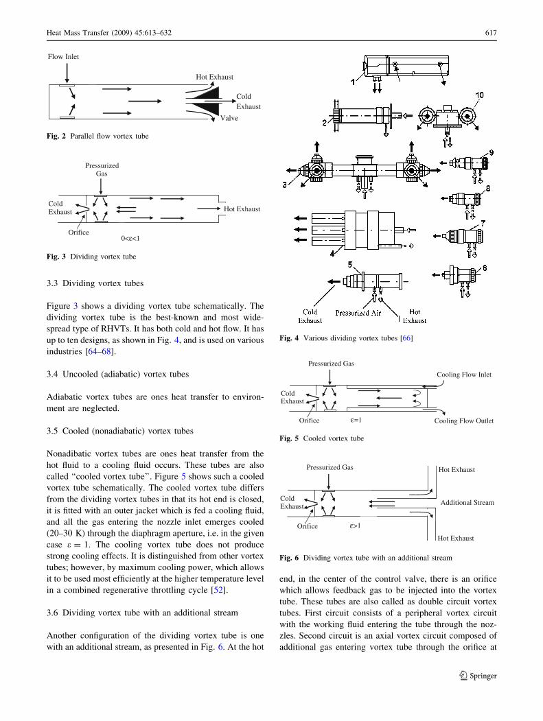
3.3 Dividing vortex tubes
Figure 3 shows a dividing vortex tube schematically. The
dividing vortex tube is the best-known and most wide-
spread type of RHVTs. It has both cold and hot flow. It has
up to ten designs, as shown in Fig. 4, and is used on various
industries [64–68].
3.4 Uncooled (adiabatic) vortex tubes
Adiabatic vortex tubes are ones heat transfer to environ-
ment are neglected.
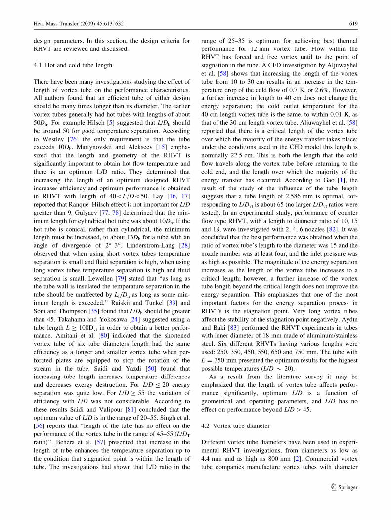
3.5 Cooled (nonadiabatic) vortex tubes
Nonadibatic vortex tubes are ones heat transfer from the
hot fluid to a cooling fluid occurs. These tubes are also
called ‘‘cooled vortex tube’’. Figure 5 shows such a cooled
vortex tube schematically. The cooled vortex tube differs
from the dividing vortex tubes in that its hot end is closed,
it is fitted with an outer jacket which is fed a cooling fluid,
and all the gas entering the nozzle inlet emerges cooled
(20–30 K) through the diaphragm aperture, i.e. in the given
case e = 1. The cooling vortex tube does not produce
strong cooling effects. It is distinguished from other vortex
tubes; however, by maximum cooling power, which allows
it to be used most efficiently at the higher temperature level
in a combined regenerative throttling cycle [52].
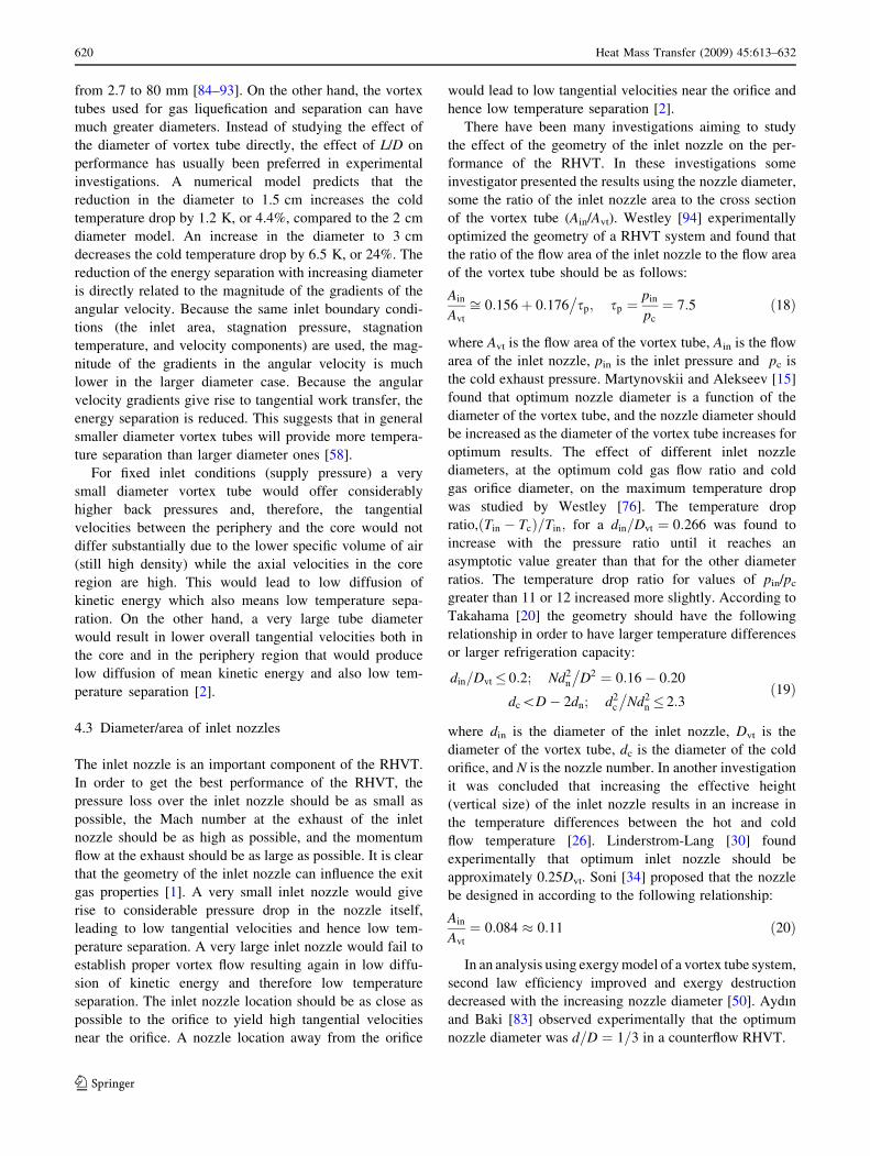
3.6 Dividing vortex tube with an additional stream
Another configuration of the dividing vortex tube is one
with an additional stream, as presented in Fig. 6. At the hot
end, in the center of the control valve, there is an orifice
which allows feedback gas to be injected into the vortex
tube. These tubes are also called as double circuit vortex
tubes. First circuit consists of a peripheral vortex circuit
with the working fluid entering the tube through the noz-
zles. Second circuit is an axial vortex circuit composed of
additional gas entering vortex tube through the orifice at
Flow Inlet
Hot Exhaust
Valve
ColdExhaust
Fig. 2 Parallel flow vortex tube
PressurizedGas
Hot Exhaust
Orifice
ColdExhaust
0<ε<1
Fig. 3 Dividing vortex tube
Pressurized Gas
Orifice
ColdExhaust
Cooling Flow Outlet
Cooling Flow Inlet
ε=1
Fig. 5 Cooled vortex tube
Fig. 4 Various dividing vortex tubes [66]
Pressurized Gas
Orifice
ColdExhaust Additional Stream
Hot Exhaust
ε>1
Hot Exhaust
Fig. 6 Dividing vortex tube with an additional stream
Heat Mass Transfer (2009) 45:613–632 617
123
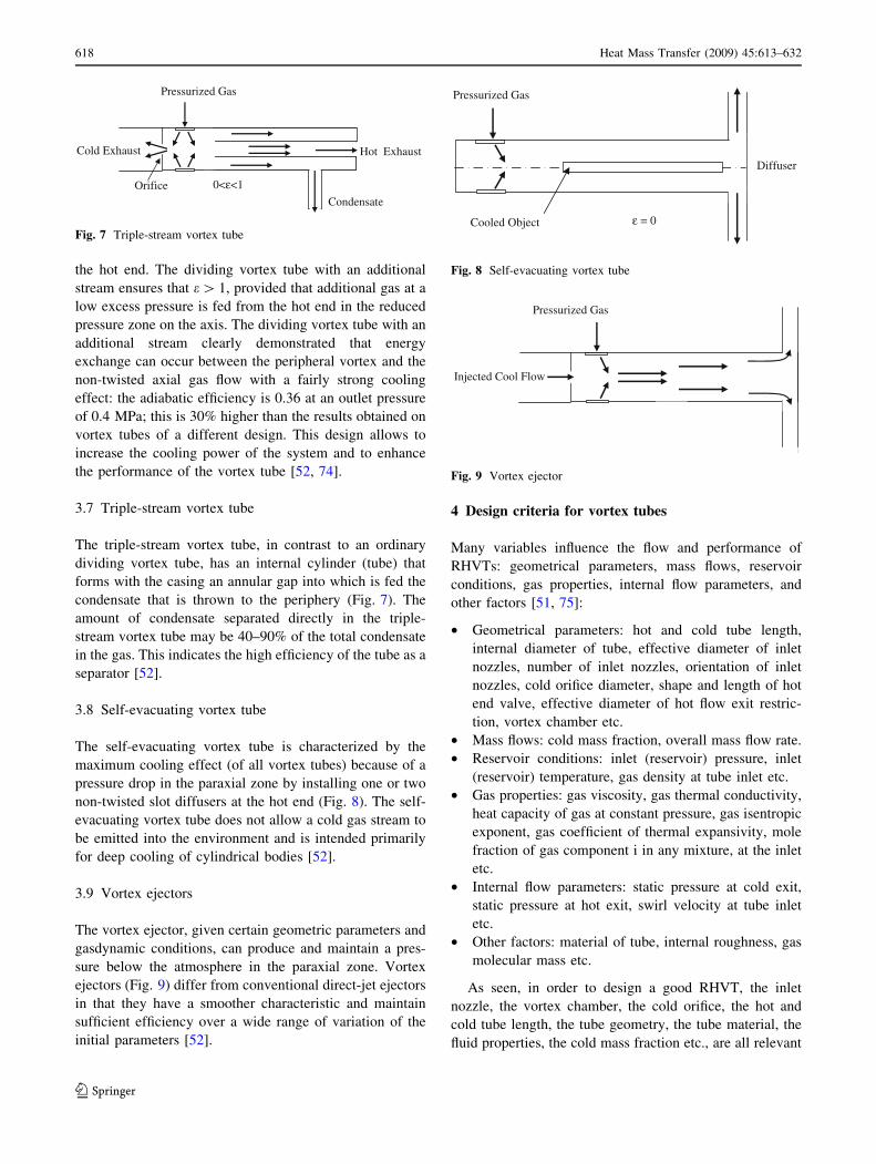
the hot end. The dividing vortex tube with an additional
stream ensures that e [ 1, provided that additional gas at a
low excess pressure is fed from the hot end in the reduced
pressure zone on the axis. The dividing vortex tube with an
additional stream clearly demonstrated that energy
exchange can occur between the peripheral vortex and the
non-twisted axial gas flow with a fairly strong cooling
effect: the adiabatic efficiency is 0.36 at an outlet pressure
of 0.4 MPa; this is 30% higher than the results obtained on
vortex tubes of a different design. This design allows to
increase the cooling power of the system and to enhance
the performance of the vortex tube [52, 74].
3.7 Triple-stream vortex tube
The triple-stream vortex tube, in contrast to an ordinary
dividing vortex tube, has an internal cylinder (tube) that
forms with the casing an annular gap into which is fed the
condensate that is thrown to the periphery (Fig. 7). The
amount of condensate separated directly in the triple-
stream vortex tube may be 40–90% of the total condensate
in the gas. This indicates the high efficiency of the tube as a
separator [52].
3.8 Self-evacuating vortex tube
The self-evacuating vortex tube is characterized by the
maximum cooling effect (of all vortex tubes) because of a
pressure drop in the paraxial zone by installing one or two
non-twisted slot diffusers at the hot end (Fig. 8). The self-
evacuating vortex tube does not allow a cold gas stream to
be emitted into the environment and is intended primarily
for deep cooling of cylindrical bodies [52].
3.9 Vortex ejectors
The vortex ejector, given certain geometric parameters and
gasdynamic conditions, can produce and maintain a pres-
sure below the atmosphere in the paraxial zone. Vortex
ejectors (Fig. 9) differ from conventional direct-jet ejectors
in that they have a smoother characteristic and maintain
sufficient efficiency over a wide range of variation of the
initial parameters [52].
4 Design criteria for vortex tubes
Many variables influence the flow and performance of
RHVTs: geometrical parameters, mass flows, reservoir
conditions, gas properties, internal flow parameters, and
other factors [51, 75]:
• Geometrical parameters: hot and cold tube length,
internal diameter of tube, effective diameter of inlet
nozzles, number of inlet nozzles, orientation of inlet
nozzles, cold orifice diameter, shape and length of hot
end valve, effective diameter of hot flow exit restric-
tion, vortex chamber etc.
• Mass flows: cold mass fraction, overall mass flow rate.
• Reservoir conditions: inlet (reservoir) pressure, inlet
(reservoir) temperature, gas density at tube inlet etc.
• Gas properties: gas viscosity, gas thermal conductivity,
heat capacity of gas at constant pressure, gas isentropic
exponent, gas coefficient of thermal expansivity, mole
fraction of gas component i in any mixture, at the inlet
etc.
• Internal flow parameters: static pressure at cold exit,
static pressure at hot exit, swirl velocity at tube inlet
etc.
• Other factors: material of tube, internal roughness, gas
molecular mass etc.
As seen, in order to design a good RHVT, the inlet
nozzle, the vortex chamber, the cold orifice, the hot and
cold tube length, the tube geometry, the tube material, the
fluid properties, the cold mass fraction etc., are all relevant
Pressurized Gas
Orifice
Cold Exhaust Hot Exhaust
Condensate
0<ε<1
Fig. 7 Triple-stream vortex tube
Pressurized Gas
Cooled Object
Diffuser
ε = 0
Fig. 8 Self-evacuating vortex tube
Pressurized Gas
Injected Cool Flow
Fig. 9 Vortex ejector
618 Heat Mass Transfer (2009) 45:613–632
123
design parameters. In this section, the design criteria for
RHVT are reviewed and discussed.
4.1 Hot and cold tube length
There have been many investigations studying the effect of
length of vortex tube on the performance characteristics.
All authors found that an efficient tube of either design
should be many times longer than its diameter. The earlier
vortex tubes generally had hot tubes with lengths of about
50Dh. For example Hilsch [5] suggested that L/Dh should
be around 50 for good temperature separation. According
to Westley [76] the only requirement is that the tube
exceeds 10Dh. Martynovskii and Alekseev [15] empha-
sized that the length and geometry of the RHVT is
significantly important to obtain hot flow temperature and
there is an optimum L/D ratio. They determined that
increasing the length of an optimum designed RHVT
increases efficiency and optimum performance is obtained
in RHVT with length of 40\L=D\50: Lay [16, 17]
reported that Ranque–Hilsch effect is not important for L/D
greater than 9. Gulyaev [77, 78] determined that the min-
imum length for cylindrical hot tube was about 10Dh. If the
hot tube is conical, rather than cylindrical, the minimum
length must be incresaed, to about 13Dh for a tube with an
angle of divergence of 2�–3�. Linderstrom-Lang [28]
observed that when using short vortex tubes temperature
separation is small and fluid separation is high, when using
long vortex tubes temperature separation is high and fluid
separation is small. Lewellen [79] stated that ‘‘as long as
the tube wall is insulated the temperature separation in the
tube should be unaffected by Lh/Dh as long as some min-
imum length is exceeded.’’ Raiskii and Tunkel [33] and
Soni and Thompson [35] found that L/Dh should be greater
than 45. Takahama and Yokosawa [24] suggested using a
tube length L C 100Dvt in order to obtain a better perfor-
mance. Amitani et al. [80] indicated that the shortened
vortex tube of six tube diameters length had the same
efficiency as a longer and smaller vortex tube when per-
forated plates are equipped to stop the rotation of the
stream in the tube. Saidi and Yazdi [50] found that
increasing tube length increases temperature differences
and decreases exergy destruction. For L/D B 20 energy
separation was quite low. For L/D C 55 the variation of
efficiency with L/D was not considerable. According to
these results Saidi and Valipour [81] concluded that the
optimum value of L/D is in the range of 20–55. Singh et al.
[56] reports that ‘‘length of the tube has no effect on the
performance of the vortex tube in the range of 45–55 (L/DT
ratio)’’. Behera et al. [57] presented that increase in the
length of tube enhances the temperature separation up to
the condition that stagnation point is within the length of
tube. The investigations had shown that L/D ratio in the
range of 25–35 is optimum for achieving best thermal
performance for 12 mm vortex tube. Flow within the
RHVT has forced and free vortex until to the point of
stagnation in the tube. A CFD investigation by Aljuwayhel
et al. [58] shows that increasing the length of the vortex
tube from 10 to 30 cm results in an increase in the tem-
perature drop of the cold flow of 0.7 K, or 2.6%. However,
a further increase in length to 40 cm does not change the
energy separation; the cold outlet temperature for the
40 cm length vortex tube is the same, to within 0.01 K, as
that of the 30 cm length vortex tube. Aljuwayhel et al. [58]
reported that there is a critical length of the vortex tube
over which the majority of the energy transfer takes place;
under the conditions used in the CFD model this length is
nominally 22.5 cm. This is both the length that the cold
flow travels along the vortex tube before returning to the
cold end, and the length over which the majority of the
energy transfer has occurred. According to Gao [1], the
result of the study of the influence of the tube length
suggests that a tube length of 2,586 mm is optimal, cor-
responding to L/Dvt is about 65 (no larger L/Dvt ratios were
tested). In an experimental study, performance of counter
flow type RHVT, with a length to diameter ratio of 10, 15
and 18, were investigated with 2, 4, 6 nozzles [82]. It was
concluded that the best performance was obtained when the
ratio of vortex tube’s length to the diameter was 15 and the
nozzle number was at least four, and the inlet pressure was
as high as possible. The magnitude of the energy separation
increases as the length of the vortex tube increases to a
critical length; however, a further increase of the vortex
tube length beyond the critical length does not improve the
energy separation. This emphasizes that one of the most
important factors for the energy separation process in
RHVTs is the stagnation point. Very long vortex tubes
affect the stability of the stagnation point negatively. Aydınand Baki [83] performed the RHVT experiments in tubes
with inner diameter of 18 mm made of aluminum/stainless
steel. Six different RHVTs having various lengths were
used: 250, 350, 450, 550, 650 and 750 mm. The tube with
L = 350 mm presented the optimum results for the highest
possible temperatures (L/D * 20).
As a result from the literature survey it may be
emphasized that the length of vortex tube affects perfor-
mance significantly, optimum L/D is a function of
geometrical and operating parameters, and L/D has no
effect on performance beyond L/D [ 45.
4.2 Vortex tube diameter
Different vortex tube diameters have been used in experi-
mental RHVT investigations, from diameters as low as
4.4 mm and as high as 800 mm [2]. Commercial vortex
tube companies manufacture vortex tubes with diameter
Heat Mass Transfer (2009) 45:613–632 619
123
from 2.7 to 80 mm [84–93]. On the other hand, the vortex
tubes used for gas liquefication and separation can have
much greater diameters. Instead of studying the effect of
the diameter of vortex tube directly, the effect of L/D on
performance has usually been preferred in experimental
investigations. A numerical model predicts that the
reduction in the diameter to 1.5 cm increases the cold
temperature drop by 1.2 K, or 4.4%, compared to the 2 cm
diameter model. An increase in the diameter to 3 cm
decreases the cold temperature drop by 6.5 K, or 24%. The
reduction of the energy separation with increasing diameter
is directly related to the magnitude of the gradients of the
angular velocity. Because the same inlet boundary condi-
tions (the inlet area, stagnation pressure, stagnation
temperature, and velocity components) are used, the mag-
nitude of the gradients in the angular velocity is much
lower in the larger diameter case. Because the angular
velocity gradients give rise to tangential work transfer, the
energy separation is reduced. This suggests that in general
smaller diameter vortex tubes will provide more tempera-
ture separation than larger diameter ones [58].
For fixed inlet conditions (supply pressure) a very
small diameter vortex tube would offer considerably
higher back pressures and, therefore, the tangential
velocities between the periphery and the core would not
differ substantially due to the lower specific volume of air
(still high density) while the axial velocities in the core
region are high. This would lead to low diffusion of
kinetic energy which also means low temperature sepa-
ration. On the other hand, a very large tube diameter
would result in lower overall tangential velocities both in
the core and in the periphery region that would produce
low diffusion of mean kinetic energy and also low tem-
perature separation [2].
4.3 Diameter/area of inlet nozzles
The inlet nozzle is an important component of the RHVT.
In order to get the best performance of the RHVT, the
pressure loss over the inlet nozzle should be as small as
possible, the Mach number at the exhaust of the inlet
nozzle should be as high as possible, and the momentum
flow at the exhaust should be as large as possible. It is clear
that the geometry of the inlet nozzle can influence the exit
gas properties [1]. A very small inlet nozzle would give
rise to considerable pressure drop in the nozzle itself,
leading to low tangential velocities and hence low tem-
perature separation. A very large inlet nozzle would fail to
establish proper vortex flow resulting again in low diffu-
sion of kinetic energy and therefore low temperature
separation. The inlet nozzle location should be as close as
possible to the orifice to yield high tangential velocities
near the orifice. A nozzle location away from the orifice
would lead to low tangential velocities near the orifice and
hence low temperature separation [2].
There have been many investigations aiming to study
the effect of the geometry of the inlet nozzle on the per-
formance of the RHVT. In these investigations some
investigator presented the results using the nozzle diameter,
some the ratio of the inlet nozzle area to the cross section
of the vortex tube (Ain/Avt). Westley [94] experimentally
optimized the geometry of a RHVT system and found that
the ratio of the flow area of the inlet nozzle to the flow area
of the vortex tube should be as follows:
Ain
Avt
ffi 0:156þ 0:176�sp; sp ¼
pin
pc
¼ 7:5 ð18Þ
where Avt is the flow area of the vortex tube, Ain is the flow
area of the inlet nozzle, pin is the inlet pressure and pc is
the cold exhaust pressure. Martynovskii and Alekseev [15]
found that optimum nozzle diameter is a function of the
diameter of the vortex tube, and the nozzle diameter should
be increased as the diameter of the vortex tube increases for
optimum results. The effect of different inlet nozzle
diameters, at the optimum cold gas flow ratio and cold
gas orifice diameter, on the maximum temperature drop
was studied by Westley [76]. The temperature drop
ratio, Tin � Tcð Þ=Tin; for a din=Dvt ¼ 0:266 was found to
increase with the pressure ratio until it reaches an
asymptotic value greater than that for the other diameter
ratios. The temperature drop ratio for values of pin/pc
greater than 11 or 12 increased more slightly. According to
Takahama [20] the geometry should have the following
relationship in order to have larger temperature differences
or larger refrigeration capacity:
din=Dvt� 0:2; Nd2n
�D2 ¼ 0:16� 0:20
dc\D� 2dn; d2c
�Nd2
n � 2:3ð19Þ
where din is the diameter of the inlet nozzle, Dvt is the
diameter of the vortex tube, dc is the diameter of the cold
orifice, and N is the nozzle number. In another investigation
it was concluded that increasing the effective height
(vertical size) of the inlet nozzle results in an increase in
the temperature differences between the hot and cold
flow temperature [26]. Linderstrom-Lang [30] found
experimentally that optimum inlet nozzle should be
approximately 0.25Dvt. Soni [34] proposed that the nozzle
be designed in according to the following relationship:
Ain
Avt
¼ 0:084 � 0:11 ð20Þ
In an analysis using exergy model of a vortex tube system,
second law efficiency improved and exergy destruction
decreased with the increasing nozzle diameter [50]. Aydınand Baki [83] observed experimentally that the optimum
nozzle diameter was d=D ¼ 1=3 in a counterflow RHVT.
620 Heat Mass Transfer (2009) 45:613–632
123

All these investigations prove that increasing nozzle
diameter, generally, increases the performance and the
optimum nozzle diameter is about to be 0.25 Dvt.
4.4 Type and number of inlet nozzles
In vortex tubes, types of vortex chambers, types and
number of inlet nozzles are quite important. Many inves-
tigations have been carried out on different types and
number of nozzles to arrive at the optimum profile of the
inlet nozzle and number of nozzle(s). All investigations
reported that the inlet nozzles should be designed so that
the flow be tangentially into vortex tube. Most vortex
chambers are circular with a single circular nozzle inlet.
Martynovskii and Alekseev [15] designed three different
chamber configurations, including one called a ‘‘Hilsch
Whorl’’, and concluded that a circular chamber with two
nozzles was the most efficient. In 1957, Westley [76] used
multiple rectangular nozzles entering a circular chamber.
Reynolds [95–97] suggested that the inlet nozzle should be
in the form of a slot. Reynolds suggested having more slots
in the RHVT. He noted that more slots do improve the
performance as well. Metenin [98] used six tangential
nozzles and in 1964 he designed one nozzle called as Ar-
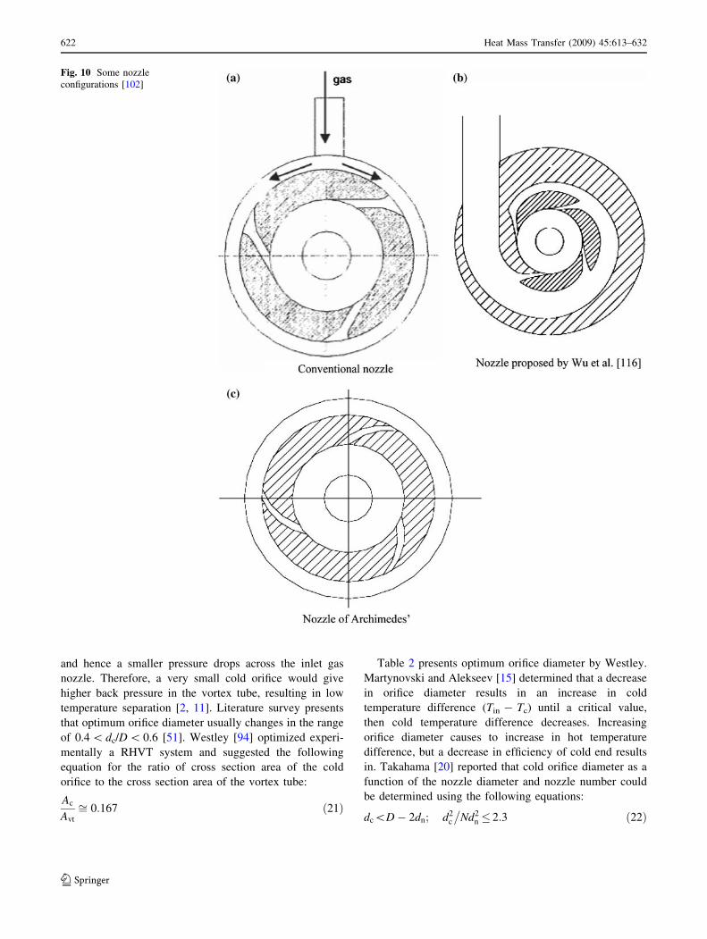
chimedian spiral, as shown in Fig. 10c, [99]. Parulekar
[100] suggested that the designs of the vortex chamber and
the inlet nozzle are very important, and he mentioned that
the inlet nozzle should have an Archimedian spiral shape
and its cross section should be slotted. A single rectangular
nozzle was used by Leites et al. [101] on their large
industrial vortex tube. Saidi and Valipour [81] conducted
experimental investigations using vortex tubes with three
and four nozzles. The results showed the nozzle with three
intakes presents better performance than four intakes noz-
zle from the point of view of refrigeration efficiency.
Promvonge and Eiamsa-ard [60] experimentally studied
the energy and temperature separations in the vortex tube
with a snail entrance. In their experimental results, the use
of snail entrance could help to increase the cold air tem-
perature drop and to improve the vortex tube efficiency in
comparison with those of original tangential inlet nozzles.
In another investigation Promvonge and Eiamsa-ard [61]
concluded that ‘‘the increase of the number of inlet nozzles
led to higher temperature separation in the vortex tube’’.
Behera et al. [57] suggest that optimum nozzle profile and
number can be determined by using CFD analysis. They
used five different nozzle configurations in a vortex tube of
12 mm diameter: two numbers of convergent nozzles,
single helical circular nozzle, single helical rectangular
nozzle, straight six numbers of nozzles, and convergent six
numbers of nozzles. The performance of the nozzles has
been characterized by the magnitude of swirl velocity and
radial symmetry of flow. Among them the nozzle
configuration with six numbers of convergent nozzles
yielded the highest swirl velocity, and radial symmetry of
flow was obtained along with good swirl velocity, which
resulted in the highest total temperature difference com-
pared to all the nozzle profiles. Two typical nozzle
geometries were studied by Gao [1]: a conical nozzle and a
convergent (linear) slot nozzle with constant width. He
determined that the optimization occurs by using a short
slot and more number of slots. According to Gao [1]
applying a slot-ring instead of the nozzle ring, using a large
number of slots and using a larger exhaust tube to decrease
the exhaust pressures all can increase the temperature dif-
ferences and improve the performance. Dincer et al. [82]
conducted experimental investigation in vortex tubes with
15 L/D ratio. The vortex tubes with 4 and 6 nozzles yields
better performance than the vortex tube with 2 nozzles. The
vortex tube with 4 nozzles gave the best performance. In
2007, Wu et al. [102] used a new nozzle with equal Mach
number gradient and an intake flow passage with equal
flow velocity in the modified vortex tube (Fig. 10b). The
experimental results indicated that the cooling effect of the
improved nozzle is about 2.2�C lower than that of the
nozzle with normal rectangle and even 5�C lower than that
of the nozzle with Archimedes’ spiral.
Some investigations that study the effect of nozzle
number on the performance of RHVT suggest that
increasing nozzle number improves temperature separa-
tion; others suggest that the performance of RHVT
decreases with increasing nozzle number. According to the
first group investigators increasing nozzle number results in
flow to accelerate and flow rate to increase. Strong swirling
flow inside the vortex tube is created. In addition this
causes high friction dissipation between the flow layers and
high momentum transfer from central to circumferential
regions. Finally flow temperature in central region
decreases and those in circumferential regions increases.
According to other investigators as nozzle number increa-
ses the flow inside the vortex tube becomes more turbulent
due to interactions of the inlet flows, hot and cold flow
mixes and thus temperature separation decreases.
4.5 Cold orifice
The optimum cold orifice diameter is a function of the gas
flow rate through the orifice; hence it is a function of the
pressure drop across the orifice and the cold gas mass flow
ratio. If the orifice is too large, hot gas from the outer edge
of the vortex is drawn through the orifice with the colder
inner gas. Therefore, a very large cold orifice would tend to
draw air directly from the inlet and yield weaker tangential
velocities near the inlet region, resulting in low tempera-
ture separation. However, if the orifice diameter is too
small, there is a significant pressure drop across the orifice,
Heat Mass Transfer (2009) 45:613–632 621
123
and hence a smaller pressure drops across the inlet gas
nozzle. Therefore, a very small cold orifice would give
higher back pressure in the vortex tube, resulting in low
temperature separation [2, 11]. Literature survey presents
that optimum orifice diameter usually changes in the range
of 0.4 \ dc/D \ 0.6 [51]. Westley [94] optimized experi-
mentally a RHVT system and suggested the following
equation for the ratio of cross section area of the cold
orifice to the cross section area of the vortex tube:
Ac
Avt
ffi 0:167 ð21Þ
Table 2 presents optimum orifice diameter by Westley.
Martynovski and Alekseev [15] determined that a decrease
in orifice diameter results in an increase in cold
temperature difference (Tin - Tc) until a critical value,
then cold temperature difference decreases. Increasing
orifice diameter causes to increase in hot temperature
difference, but a decrease in efficiency of cold end results
in. Takahama [20] reported that cold orifice diameter as a
function of the nozzle diameter and nozzle number could
be determined using the following equations:
dc\D� 2dn; d2c
�Nd2
n � 2:3 ð22Þ
Fig. 10 Some nozzle
configurations [102]
622 Heat Mass Transfer (2009) 45:613–632
123
Merkulov [103] suggested the following equation for
dimensionless cold orifice diameter ratio.
dc
D¼ 0:35þ 0:313e ð23Þ
Soni [34] carried investigations with 170 different
RHVT and suggested the following equation:
Ac
Avt
¼ 0:08 � 0:145 ð24Þ
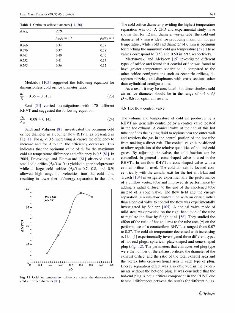
Saidi and Valipour [81] investigated the optimum cold
orifice diameter in a counter flow RHVT, as presented in
Fig. 11. For dc \ 0.5, increasing dc causes the efficiency to
increase and for dc [ 0.5, the efficiency decreases. This
indicates that the optimum value of dc for the maximum
cold air temperature difference and efficiency is 0.5 [81]. In
2005, Promvonge and Eiamsa-ard [61] observed that a
small cold orifice (dc/D = 0.4) yielded higher backpressure
while a large cold orifice (dc/D = 0.7, 0.8, and 0.9)
allowed high tangential velocities into the cold tube,
resulting in lower thermal/energy separation in the tube.
The cold orifice diameter providing the highest temperature
separation was 0.5. A CFD and experimental study have
shown that for 12 mm diameter vortex tube, the cold end
diameter of 7 mm is ideal for producing maximum hot gas
temperature, while cold end diameter of 6 mm is optimum
for reaching the minimum cold gas temperature [57]. These
values correspond to 0.58 and 0.50 in L/D, respectively.
Martynovski and Alekseev [15] investigated different
types of orifice and found that coaxial orifice was found to
have greater temperature separation in compared to the
other orifice configurations such as eccentric orifices, di-
aphram nozzles, and diaphrams with cross sections other
than cylindrical configurations.
As a result it may be concluded that dimensionless cold
air orifice diameter should be in the range of 0.4 \ dc/
D \ 0.6 for optimum results.
4.6 Hot flow control valve
The volume and temperature of cold air produced by a
RHVT are generally controlled by a control valve located
in the hot exhaust. A conical valve at the end of this hot
tube confines the exiting fluid to regions near the outer wall
and restricts the gas in the central portion of the hot tube
from making a direct exit. The conical valve is positioned
to allow regulation of the relative quantities of hot and cold
gases. By adjusting the valve, the cold fraction can be
controlled. In general a cone-shaped valve is used in the
RHVTs. In uni-flow RHVTs a cone-shaped valve with a
central orifice is used. The cold air exit is located con-
centrically with the annular exit for the hot air. Blatt and
Trusch [104] investigated experimentally the performance
of a uniflow vortex tube and improved its performance by
adding a radial diffuser to the end of the shortened tube
instead of a cone valve. The flow field and the energy
separation in a uni-flow vortex tube with an orifice rather
than a conical valve to control the flow was experimentally
investigated by Schlenz [105]. A conical valve made of
mild steel was provided on the right hand side of the tube
to regulate the flow by Singh et al. [56]. They studied the
effect of the ratio of hot end area to the tube area (a) on the
performance of a counterflow RHVT. a ranged from 0.07
to 0.27. The cold air temperature decreased with increasing
a. Gao [1] experimentally investigated three different types
of hot end plugs: spherical, plate-shaped and cone-shaped
plug (Fig. 12). The parameters that characterized plug type
were the number of the exhaust orifices, the diameter of the
exhaust orifice, and the ratio of the total exhaust area and
the vortex tube cross-sectional area in each type of plug.
Energy separation effect was also observed in the experi-
ments without the hot-end plug. It was concluded that the
hot-end plug is not a critical component in the RHVT due
to small differences between the results for different plugs.
Table 2 Optimum orifice diameters [11, 76]
dn/Dh dc/Dh
pin/pc = 1.5 pin/pc = 7
0.266 0.34 0.38
0.376 0.37 0.38
0.461 0.40 0.40
0.532 0.41 0.37
0.595 0.36 0.32
Fig. 11 Cold air temperature difference versus the dimensionless
cold air orifice diameter [81]
Heat Mass Transfer (2009) 45:613–632 623
123

Aydın and Baki [83] investigated the effect of the angle of
the cone-shaped control valve on the performance of a
counterflow RHVT, changing the vane angle from 45� to
60�. The angle of the control valve yielding the optimum
performance was 50�. Wu et al. [102] designed and
installed a diffuser between the outlet of vortex tube and
hot valve aiming to reducing the peripheral speed to zero
within very short pipe and greatly reduce the ratio of length
to diameter. It was determined that the cooling effect of the
vortex tube with diffuser was up to 5�C lower than that
without diffuser.
4.7 Tube geometry
Cylindrical geometry is usually used in RHVTs. Many
investigations have been conducted in order to study the
effect of tapering the RHVT. Martynovskii and Alekseev
[15] found that a contracting and expanding vortex tubes
had little effect on temperature separation; however, a
contracting hot tube to be preferable. Otten [106] presented
that the vortex tube performance could be improved by
using a conical tube. It was found that an additional tem-
perature drop of nearly 20�C at a cold mass flow ratio of
0.1, 10�C for a ratio of about 0.5, and almost no effect at
ratios larger than 0.9. Parulekar [100] designed a short
conical vortex tube. By varying the conical angle of the
vortex tube, he found that the parameter Lvt/Dvt could be as
small as 3. In 1964, Metenin [99] found that conical vortex
tubes with a length of only 3Dh perform satisfactorily if a
diffuser is added to the end of the hot tube. According to
Gulyaev [78] a conical expansion brings improvements.
The vortex tube with a conical angle of about 2.3� sur-
passed the best cylinder tube by 20–25% for the thermal
efficiency and the refrigeration capacity. Borisenko et al.
[31] concluded that a conical cold tube had no effect on a
counterflow tube, while a 3� conical expansion in the hot
tube resulted in optimal performance. Raiskii and Tunkel
[33] in contrast found it is impossible to better performance
of a cylindrical hot tube, noting that the majority of the
energy transfer appears to occur within the first five
diameters of the tube. In order to shorten the tube length,
Takahama and Yokosawa [24] introduced the divergent (or
conical) vortex tube. This divergent vortex tube could
reach the same performance as the normal tube but with a
smaller length. Because within the divergent tube the cross
sectional area increases to the hot end, the gradient of the
gas axial velocity decreases. He suggested that the diver-
gence angle should be in the range 1.7�–5.1�. Gao [1]
determined that rounding off the tube entrance increases
the cold fraction in the RHVT system under the same
operating conditions, and enhances the secondary circula-
tion inside the RHVT itself and extends the circulation
closer to the vortex chamber in the RHVT, at last improves
the performance of the RHVT. The conical vortex tube was
further investigated by Poshernev in 2003 and 2004 [53,
54] for chemical applications.
It is widely known that the RHVT system creates strong
noise levels. In order to reduce the sound level and convert
the acoustic energy into heat, in 1982 Kurosaka [37] and
Chu [107], in 1983 Kuroda [108] introduced an acoustic
muffler. They found that with the muffler the performance
of the system was better than without.
The above investigations on the effect of tapering the
RHVT present conflicting results. Although some investi-
gators conclude that tapering the vortex tube for heating
purposes have no effect on the performance, the others
state that small tapering angles (*3�) leads to optimum
results. With all research on divergent vortex tubes, it can
be found that there exists an optimal conical angle and this
angle is very small. This can be attributed slowing down
the azimuthal motion of the flow. When the flow swirls to
the hot end the cross section area increases, and so the
azimuthal motion is slowed down along its path. Tapering
the vortex tube contributes separation process in vortex
tubes used for gas separation. Rounding off the tube
entrance improves the performance of the RHVT [1, 24].
Fig. 12 The hot-end plugs used by Gao [1]
624 Heat Mass Transfer (2009) 45:613–632
123
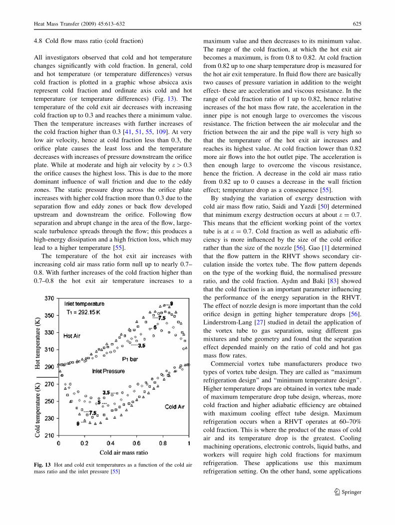
4.8 Cold flow mass ratio (cold fraction)
All investigators observed that cold and hot temperature
changes significantly with cold fraction. In general, cold
and hot temperature (or temperature differences) versus
cold fraction is plotted in a graphic whose absicca axis
represent cold fraction and ordinate axis cold and hot
temperature (or temperature differences) (Fig. 13). The
temperature of the cold exit air decreases with increasing
cold fraction up to 0.3 and reaches there a minimum value.
Then the temperature increases with further increases of
the cold fraction higher than 0.3 [41, 51, 55, 109]. At very
low air velocity, hence at cold fraction less than 0.3, the
orifice plate causes the least loss and the temperature
decreases with increases of pressure downstream the orifice
plate. While at moderate and high air velocity by e[ 0.3
the orifice causes the highest loss. This is due to the more
dominant influence of wall friction and due to the eddy
zones. The static pressure drop across the orifice plate
increases with higher cold fraction more than 0.3 due to the
separation flow and eddy zones or back flow developed
upstream and downstream the orifice. Following flow
separation and abrupt change in the area of the flow, large-
scale turbulence spreads through the flow; this produces a
high-energy dissipation and a high friction loss, which may
lead to a higher temperature [55].
The temperature of the hot exit air increases with
increasing cold air mass ratio form null up to nearly 0.7–
0.8. With further increases of the cold fraction higher than
0.7–0.8 the hot exit air temperature increases to a
maximum value and then decreases to its minimum value.
The range of the cold fraction, at which the hot exit air
becomes a maximum, is from 0.8 to 0.82. At cold fraction
from 0.82 up to one sharp temperature drop is measured for
the hot air exit temperature. In fluid flow there are basically
two causes of pressure variation in addition to the weight
effect- these are acceleration and viscous resistance. In the
range of cold fraction ratio of 1 up to 0.82, hence relative
increases of the hot mass flow rate, the acceleration in the
inner pipe is not enough large to overcomes the viscous
resistance. The friction between the air molecular and the
friction between the air and the pipe wall is very high so
that the temperature of the hot exit air increases and
reaches its highest value. At cold fraction lower than 0.82
more air flows into the hot outlet pipe. The acceleration is
then enough large to overcome the viscous resistance,
hence the friction. A decrease in the cold air mass ratio
from 0.82 up to 0 causes a decrease in the wall friction
effect; temperature drop as a consequence [55].
By studying the variation of exergy destruction with
cold air mass flow ratio, Saidi and Yazdi [50] determined
that minimum exergy destruction occurs at about e = 0.7.
This means that the efficient working point of the vortex
tube is at e = 0.7. Cold fraction as well as adiabatic effi-
ciency is more influenced by the size of the cold orifice
rather than the size of the nozzle [56]. Gao [1] determined
that the flow pattern in the RHVT shows secondary cir-
culation inside the vortex tube. The flow pattern depends
on the type of the working fluid, the normalised pressure
ratio, and the cold fraction. Aydın and Baki [83] showed
that the cold fraction is an important parameter influencing
the performance of the energy separation in the RHVT.
The effect of nozzle design is more important than the cold
orifice design in getting higher temperature drops [56].
Linderstrom-Lang [27] studied in detail the application of
the vortex tube to gas separation, using different gas
mixtures and tube geometry and found that the separation
effect depended mainly on the ratio of cold and hot gas
mass flow rates.
Commercial vortex tube manufacturers produce two
types of vortex tube design. They are called as ‘‘maximum
refrigeration design’’ and ‘‘minimum temperature design’’.
Higher temperature drops are obtained in vortex tube made
of maximum temperature drop tube design, whereas, more
cold fraction and higher adiabatic efficiency are obtained
with maximum cooling effect tube design. Maximum
refrigeration occurs when a RHVT operates at 60–70%
cold fraction. This is where the product of the mass of cold
air and its temperature drop is the greatest. Cooling
machining operations, electronic controls, liquid baths, and
workers will require high cold fractions for maximum
refrigeration. These applications use this maximum
refrigeration setting. On the other hand, some applicationsFig. 13 Hot and cold exit temperatures as a function of the cold air
mass ratio and the inlet pressure [55]
Heat Mass Transfer (2009) 45:613–632 625
123

require the lowest possible cold output temperature. Colder
temperatures are useful for cooling glass, cooling hot parts,
laboratory experiments, and testing of electronic compo-
nents. A low cold fraction (i.e. less than 50% of the input
air exiting through the cold air exhaust), produces the
lowest temperatures, but with reduced airflow [84–93].
4.9 Inlet pressure and temperature of gas
Martynovskii and Alekseev [15] reported that increasing
the inlet pressure resulted in large temperature difference
between hot and cold gas temperatures. In 1957, Westley
found that the reduced maximum temperature is a function
of reduced inlet pressure and it approaches an asymptotic
value as the reduced inlet pressure increases. This
asymptotic value approximately equals to a value of 0.22
for optimum cold gas flow, the optimum inlet nozzle and
the cold gas orifice diameter. For an inlet gas at 300 K, this
corresponds to a maximum temperature drop of about
66 K. Hilsch [5] determined that the temperature drop was
68 K with an inlet pressure of 11. Westley also reported
that the maximum temperature drop increases very slightly
beyond the value of pin=pc of 11 or 12. Lewellen [79]
conducted a very simplified analysis in which he predicted
an asymptotic value of about 0.185. Although this value is
somewhat lower than Westley’s asymptotic value of 0.22,
Lewellen reports that ‘‘it is close enough to suggest that the
model is basically sound.’’ Gulyaev [77] investigated vor-
tex tube performance using Helyum at temperatures of
80 K. He found that the cold gas temperature is approxi-
mately equal to a constant times the inlet temperature of
gas
Tin � Tc
Tin
¼ constant ðfor a given pin=pc and eÞ ð25Þ
At the optimum conditions the above constant should be
the same as the asymptotic value mentioned above.
According to Gulyaev the ratio, Tin � Tcð Þ= Tin � Tcð Þis;varies in the range of 0.2–0.5. The ratio equals to a value of
about 0.2 at a cold gas flow ratio of 0.8, to about 0.5 at cold
gas flow ratios around 0.2–0.3. Rather than depending on
the absolute inlet pressure, the temperature separation was
found to be a linear function of the normalised pressure drop
X ¼ pin � pcð Þ=pinð Þ between the inlet and the cold end of
the vortex tube [43]. Ahlborn et al. [43] also found that
vortex tubes behave identically in the above and below
atmospheric pressure regimes. Essential for the temperature
splitting is the normalised pressure drop X and not the
absolute entrance pressure. They concluded that safe
incorporation of vortex tubes in closed cycles that may go
below atmospheric pressures for cooling and dehydration
applications. Temperature difference increases and exergy
destruction decreases as inlet pressure increases [50].
According to Saidi and Valipour [81] the cold air
temperature difference increases by increasing the inlet
pressure, meanwhile there is an optimum efficiency at
specific inlet pressure. Shannak [55] found that a 40%
change of the inlet pressure may lead to 2% change of the
hot and cold temperature. Maximum irreversibility factor is
a function of the ratio of inlet pressure to the cold flow
pressure, (pin/pc) [1]. Aydın and Baki [83] experimentally
observed in a counterflow RHVT that the higher the inlet
pressure, the greater the temperature difference of the outlet
streams.
According to Martynovskii and Alekseev [15] inlet
temperature does not affect significantly the stagnation
temperature differences. Gulyaev [77] reported that the
ratio of Tg � Tc
� ��Tg � Tc
� �is
was nearly independent of
the inlet gas temperature. Another investigation showed
that a 2% change of inlet temperature could lead to change
the temperature of hot and cold exit air up to 2% [55]. Ma
et al. [110] observed experimentally that the hot stream
temperature and cold stream temperature increase slightly
with inlet temperature rising, whereas the temperature
difference between the hot and the cold air stream
decreases slightly with inlet temperature rising. They
concluded that the inlet temperature is not a strong factor
influencing the energy separation just in their experimental
range.
As a result it may be concluded that although the inlet
temperature has negligible effect on performance the
increase of inlet pressure enhances temperature separation.
4.10 Type of fluid
Air is generally used in vortex tubes and quite low tem-
perature drop could be obtained. There are also
investigations with working fluids such as steam, hydro-
carbons and other gases.
4.10.1 Various gases
Based on the governing equations a similarity relation, the
ratio of the actual temperature drop of the cold gas to the
maximum temperature drop, (DTc/DTcmax), for geometri-
cally similar vortex tubes was established by Stephan et al.
[39]. This similarity relation was found to be independent
from the operating conditions and the working substances
in vortex tubes that are geometrically similar. The experi-
ments conducted with air, helium and oxygen as working
media confirmed the similarity relation. Heating-cooling
temperatures of air, oxygen, carbon dioxide and nitrogen as
working fluid in vortex tubes have been investigated
experimentally [111]. Oxygen, carbon dioxide and nitrogen
provided lower cold temperatures than air. Carbon dioxide
was found to have lower hot and cold flow temperatures in
626 Heat Mass Transfer (2009) 45:613–632
123

compared the other fluids. Gao et al. [1] built a simple
vortex tube and used nitrogen as its working fluid. In 2006,
Aydın and Baki [83] obtained that nitrogen provides higher
temperature differences in compared to air and oxygen.
The reason of this behaviour was attributed to the molec-
ular weight of nitrogen, which is much smaller than that of
air and oxygen.
4.10.2 Gaseous hydrocarbons
Gaseous hydrocarbons also exhibit the Ranque–Hilsch
effect, as presented by a number of investigators. In 1971,
Williams [112] used methane in a counterflow RHVT,
obtaining performance characteristics very similar to those
of air. The measurements of Collins and Lovelace [113]
with a two-phase, liquid–vapour mixture, propane in a
standard counter-flow vortex tube showed that for an inlet
pressure of 0.791 MPa, the separation remained significant
for a dryness fraction above 80% at the inlet. With a dry-
ness fraction below 80%, the temperature separation
became insignificant. But the discharge enthalpies showed
considerable differences indicating that the Ranque–Hilsch
process is still in effect. Ahlborn et al. [45] designed vortex
tubes with R22, R134 ve R144 as working fluids.
4.10.3 Steam
Starostin and Itkin [114] reported that in order to obtain
fundamental temperature separation, greater inlet pressure
is required in steam than air. Performance of vortex tube
with steam was found to be similar to that of air. Some
criteria and expressions to estimate the energy separation
performance for steam operated vortex tube were intro-
duced by Takahama et al. [23]. Study by Takahama et al.
reveals that (1) geometrical dimensions for vortex tube
operated with air can be used for one operated with steam.
(2) As far as steam is in the superheated region at the inlet
nozzle, the energy separation performance is the same as
that for air and is presented by the same curve indepen-
dently of the degree of superheat, total mass flow rate and
discharge resistance. (3) When steam is in the wet region at
the nozzle outlet, even though steam supplied is super-
heated, the performance considerably decreases because of
the energy waste from moisture vaporization. No energy is
separated when the dryness fraction at the nozzle outlet is
less than approximately 0.98.
4.10.4 Water
In 1988, Balmer [40] introduced high pressure water as the
working medium into a commercially available counter-
flow RHVT. He showed that there is no thermodynamic
reason why energy separation in liquids should not occur,
and found experimental evidence of a radial temperature
gradient at very high inlet pressure. It was found that when
the inlet pressure is high, for instance 20–50 bar, the
energy separation effect still exists. So it proves that the
energy separation process exists in incompressible vortex
flow as well.
In general it may be stated that thermophysical charac-
teristics of fluids influence the performance of vortex tubes,
performance declines with increasing wetness fractions,
and performance characteristics for vortex tubes with
steam and hydrocarbons are very similar to those of air.
4.11 Gas properties
Otten [106] suggested a correction factor for Tin - Tc as a
function of cp/cv (k). The ratio of the specific heats is used
in connection with a plot giving the standard performance
of a vortex tube operating with air. According to Otten if
the ratio of specific heats varies with pressure or if the
Joule–Thompson effect is important, appropriate gas table
should be used. Temperature drops for various gases are
presented in Table 3 [15]. In this table cold mass flow ratio
is 0.3 and reduced pressure ratio (pin/pc) is 5.0. The lower
temperature drop of air than that of methane may be
attributed to moisture content of air. Maximum tempera-
ture drop is proportional to Prandtl number which is one of
the most important properties of gas type. Specific heat
ratio (k) is the inlet gas characteristic that affects the
amount of energy separation in the vortex tube. Cold
temperature difference increases with increasing k [56, 81].
Piralishvili and Fuzeeva [71] finds that the values of the
relative cooling of different gases lie near one straight line
described by the equation
DT
DTair
¼ 1:51� 0:295kTcr
e0
� �ð26Þ
where k is the Boltzmann constant (J/K), Tcr is the critical
temperature, and eo is the Lennard–Jones potential (the
minimum potential energy of the intermolecular
interaction).
When the inlet gas contains moisture the energy sepa-
ration and tube efficiency considerably decreases [15].
Saidi and Valipour [81] injected water into the inlet flow in
Table 3 Temperature drop variation for various gas [11, 15]
Gas Temperature drop
(Tin - Tc)
Prandtl
number
Heat capacity
ratio
Air 38.0 0.73 1.403
CH4 40.0 1.310
CO2 34.6 0.78 1.304
NH3 30.0 0.85 1.310
Heat Mass Transfer (2009) 45:613–632 627
123
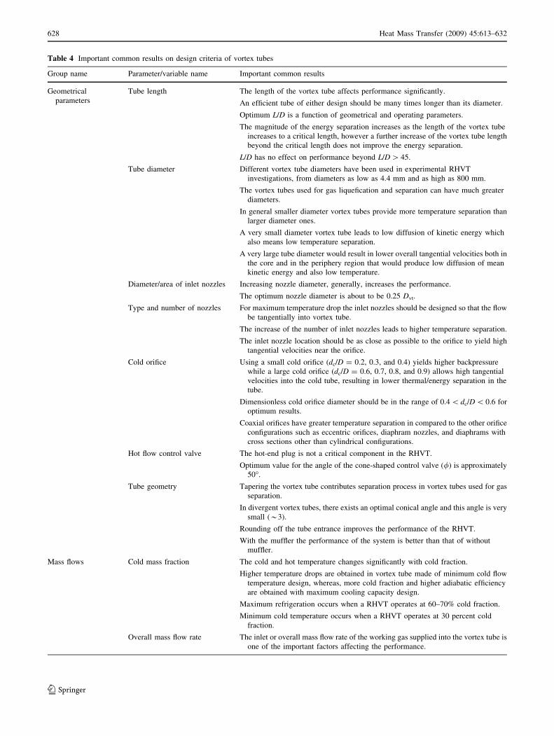
Table 4 Important common results on design criteria of vortex tubes
Group name Parameter/variable name Important common results
Geometrical
parameters
Tube length The length of the vortex tube affects performance significantly.
An efficient tube of either design should be many times longer than its diameter.
Optimum L/D is a function of geometrical and operating parameters.
The magnitude of the energy separation increases as the length of the vortex tube
increases to a critical length, however a further increase of the vortex tube length
beyond the critical length does not improve the energy separation.
L/D has no effect on performance beyond L/D [ 45.
Tube diameter Different vortex tube diameters have been used in experimental RHVT
investigations, from diameters as low as 4.4 mm and as high as 800 mm.
The vortex tubes used for gas liquefication and separation can have much greater
diameters.
In general smaller diameter vortex tubes provide more temperature separation than
larger diameter ones.
A very small diameter vortex tube leads to low diffusion of kinetic energy which
also means low temperature separation.
A very large tube diameter would result in lower overall tangential velocities both in
the core and in the periphery region that would produce low diffusion of mean
kinetic energy and also low temperature.
Diameter/area of inlet nozzles Increasing nozzle diameter, generally, increases the performance.
The optimum nozzle diameter is about to be 0.25 Dvt.
Type and number of nozzles For maximum temperature drop the inlet nozzles should be designed so that the flow
be tangentially into vortex tube.
The increase of the number of inlet nozzles leads to higher temperature separation.
The inlet nozzle location should be as close as possible to the orifice to yield high
tangential velocities near the orifice.
Cold orifice Using a small cold orifice (dc/D = 0.2, 0.3, and 0.4) yields higher backpressure
while a large cold orifice (dc/D = 0.6, 0.7, 0.8, and 0.9) allows high tangential
velocities into the cold tube, resulting in lower thermal/energy separation in the
tube.
Dimensionless cold orifice diameter should be in the range of 0.4 \ dc/D \ 0.6 for
optimum results.
Coaxial orifices have greater temperature separation in compared to the other orifice
configurations such as eccentric orifices, diaphram nozzles, and diaphrams with
cross sections other than cylindrical configurations.
Hot flow control valve The hot-end plug is not a critical component in the RHVT.
Optimum value for the angle of the cone-shaped control valve (/) is approximately
50�.
Tube geometry Tapering the vortex tube contributes separation process in vortex tubes used for gas
separation.
In divergent vortex tubes, there exists an optimal conical angle and this angle is very
small (*3).
Rounding off the tube entrance improves the performance of the RHVT.
With the muffler the performance of the system is better than that of without
muffler.
Mass flows Cold mass fraction The cold and hot temperature changes significantly with cold fraction.
Higher temperature drops are obtained in vortex tube made of minimum cold flow
temperature design, whereas, more cold fraction and higher adiabatic efficiency
are obtained with maximum cooling capacity design.
Maximum refrigeration occurs when a RHVT operates at 60–70% cold fraction.
Minimum cold temperature occurs when a RHVT operates at 30 percent cold
fraction.
Overall mass flow rate The inlet or overall mass flow rate of the working gas supplied into the vortex tube is
one of the important factors affecting the performance.
628 Heat Mass Transfer (2009) 45:613–632
123
order to determine the effect of air moisture on energy
separation. The cold temperature difference and efficiency
decreased by increasing the air moisture content of air.
4.12 Tube material
Stainless steel is usually used as tube material in vortex
tubes; however, other materials have also been used, too.
These materials may be grouped into two general classes:
metal and plastic materials. Metal materials include steel,
copper, aluminium, alloys etc., plastic materials perspex,
capralon, polystyren etc.
There have been some investigations studying the effect
of using different material on the performance of vortex
tubes. According to Parulekar [100] the roughness of the
inner surface of the tube has influence on its performance
as well: any roughness element on the inner surface of tube
will decrease the performance of the system (based on the
temperature difference) up to 20%. Saidi and Yazdi [50]
observed that steel tube gives higher temperature differ-
ences (Th - Tc) than that of PVC tube. They concluded
that using materials with more smooth surfaces and lower
thermal conductivities results in better second law effi-
ciency. According to Singh [75], the performance of the
perspex tube is generally better than that of the brass tube.
The generally lower efficiency of the brass tube could be
due to its better conductivity as compared to the perspex
tube. On the other hand perspex could be too a fragile
material to withstand the very high pressure of the inlet air.
For these reasons, the product life of the brass tube should
Table 4 continued
Group name Parameter/variable name Important common results
Reservoir conditions Inlet (reservoir) pressure The increase of inlet pressure enhances temperature separation.
Rather than depending on the absolute inlet pressure, the temperature separation is a
linear function of the normalised pressure drop between the inlet and the cold end
of the vortex tube.
The normalised maximum temperature is a function of normalised inlet pressure and
it approaches an asymptotic value as the normalised inlet pressure increases.
The maximum temperature drop increases very slightly beyond the value of pin/
pc = 11 or 12.
Vortex tubes behave identically in the above and below atmospheric pressure
regimes.
Inlet (reservoir) temperature Inlet temperature does not affect significantly the temperature differences and
performance.
Gas properties Gas Prandtl number Maximum temperature drop is proportional to Prandtl number.
Gas isentropic exponent Specific heat ratio (k) is the inlet gas characteristic that affects the amount of energy
separation in the vortex tube.
Cold temperature difference increases with increasing k.
Moisture content The cold temperature difference and efficiency decrease by increasing the air
moisture content of air.
Other factors Tube material Using materials with more smooth surfaces and lower thermal conductivities results
in better temperature separation and performance.
Using the vortex tube with insulation to reduce energy loss to surroundings gives a
higher temperature separation in the tube than that without insulation.
For all feasible operations of the vortex tube, choice of a durable material for the
manufacture of the tube is quite important.
Internal roughness The roughness of the inner surface of the tube has influence on its performance.
Any roughness element on the inner surface of tube will decrease the performance
of the system.
Using materials with more smooth surfaces results in better temperature separation
and performance.
Gas molecular mass The lighter the molecular weight, the higher the temperature separation.
Inlet gas with helium gives higher temperature difference than those found from the
oxygen, methane, and air.
Performance of RHVT with steam and hydrocarbons is similar to that of air.
When the inlet pressure is high the energy separation process exists in
incompressible vortex flow. For water very high pressures, 20–50 MPa, are
required.
Heat Mass Transfer (2009) 45:613–632 629
123

be longer. Using the tube with insulation to reduce energy
loss to surroundings gave a higher temperature separation
in the tube than that without insulation around 2–3�C for
the cold tube and 2–5�C for the hot tube [61]. Azarov [64–
68] developed many projects on vortex tubes for various
industrial applications and manufactured various vortex
tubes with different designs. Stainless steel, brass, alu-
minium, aluminium alloys, capralon, textolite etc. have
been used in these vortex tubes.
All investigators concluded that using materials with
more smooth surfaces and lower thermal conductivities,
and using the tube with insulation to reduce energy loss to
surroundings results in better temperature separation and
performance. It is important to note that for all feasible
operations of the vortex tube, choice of a durable material
for the manufacture of the tube is also quite important [115,
116].
5 Conclusions
Vortex tube is a device without moving mechanical parts,
which converts a gas flow initially homogeneous in tem-
perature, into two separate flows of differing temperatures.
Since its discovery in 1930 by Ranque, the vortex tube has
been the subject of considerable interest both from the
theoretical and practical application standpoints. However,
it is difficult to design a vortex tube with definite integral
characteristics for a concrete application because the
available experimental data are not clearly understood and
there are no entirely correct generalizations. The purpose
of this article is to overview of the past investigations of the
design criteria of vortex tubes, to draw together the mass of
literature, and to provide detailed information on the design
of vortex tubes. Thus it will be possible to access the
results of available experimental/theoretical investigations
on vortex tubes. It will be possible also to make general-
ization about design of vortex tubes. First the classification
of vortex tubes is presented and the types of vortex tubes
are described. Then all criteria on the design of vortex
tubes are given in detail using experimental and theoretical
results from the past until now. Finally the criteria on the
design of vortex tubes are summarized. Important common
findings deduced from the literature survey are tabulated
and summarized in Table 4.
Acknowledgments The authors would like to acknowledge that this
study was supported with a grant from The Scientific and Techno-
logical Research Council of Turkey, TUB_ITAK (Project No:
105M028, Project Title: Use of Vortex Tubes in Refrigeration
Technique), and Ataturk University Scientific Research Foundation
(Project No: BAP 2005/20, Project Title: Use of Vortex Tubes in
Refrigeration Technique).
References
1. Gao C (2005) Experimental study on the Ranque–Hilsch vortex
tube. PhD Thesis, Technische Universiteit Eindhoven
2. Eiamsa-ard S, Promvonge P (2007) Review of Ranque–Hilsch
effects in vortex tubes. Renew Sustain Energy Rev. doi:
10.1016/j.rser.2007.03.006
3. Ranque GJ (1933) Experiments on expansion in a vortex with
simultaneous exhaust of hot air and cold air. J Phys Radium
(Paris) 4:112–114, June. Also translated as General Electric Co.,
Schenectady Works Library 1947; T.F. 3294
4. Ranque GJ (1934) Method and apparatus for obtaining from a
fluid under pressure two outputs of fluid at different tempera-
tures. US patent 1:952,281
5. Hilsch R (1947) The use of expansion of gases in a centrifugal
field as a cooling process. Rev Sci Instrum 18(2):108–113
6. Westley R (1954) A bibliography and survey of the vortex tube.
College of Aeronautics, Cranfield note, UK
7. Curley W, McGree R Jr (1951) Bibliography of vortex tubes.
Refrig Eng 59(2):191–193
8. Kalvinskas L (1956) Vortex tubes (an extension of Wesley’s
bibliography). Jet Propulsion Laboratory, California Inst of
Technology Literature Search, 56, Part 2
9. Dobratz BM (1964) Vortex tubes: a bibliography. Lawrence
Radiation Laboratory UCRL-7829
10. Nash JM (1972) The Ranque–Hilsch vortex tube and its appli-
cation to spacecraft environmental control systems. Dev Theor
Appl Mech, p 6
11. Hellyar KG (1979) Gas liquefaction using a Ranque–Hilsch
vortex tube: design criteria and bibliography. Report for the
degree of Chemical Engineer, Massachusetts Institute of
Technology
12. Fulton CD (1950) Ranque’s tube. J ASRE Refrig Eng 58:473–
479
13. Fulton CD (1951) Comments on the vortex tube. J ASRE Refrig
Eng 59:984
14. Hartnett JP, Eckert ERG (1957) Experimental study of the
velocity and temperature distribution in a high-velocity vortex-
type flow. Trans ASME J Heat Transfer 79:751–758
15. Martynovskii VS, Alekseev VP (1957) Investigation of the
vortex thermal separation effect for gases and vapors. Sov Phys-
Tech Phys 26(2):2233–2243
16. Lay JE (1959) An experimental and analytical study of vortex
flow temperature separation by superposition of spiral and
axial flows: Part I. Trans ASME J Heat Transfer 81(4):202–
212
17. Lay JE (1959) An experimental and analytical study of vortex
flow temperature separation by superposition of spiral and axial
flows: Part II. Trans ASME J Heat Transfer 81(4):213–222
18. Deissler RG, Perlmutter M (1958) An analysis of the energy
separation in laminar and turbulent compressible vortex flows.
Heat Transfer and Fluid Mechanics Institute, Stanford Univer-
sity Press
19. Deissler RG, Perlmutter M (1960) Analysis of the flow and
energy separation in a vortex tube. Int J Heat Mass Transfer
1:173–191
20. Takahama H (1965) Studies on vortex tubes. Bull Jpn Soc Mech
Eng 8(31):433–440
21. Takahama H, Ikeda T, Kawamura H (1973) Japan Soc Mech
Eng 77:733–734
22. Takahama H, Soga N (1966) Studies on vortex tubes 2nd report,
Reynolds no. the effects of the cold air rate and partial admis-
sion of nozzle on the energy separation. Bull Jpn Soc Mech Eng
9(33):121–130
630 Heat Mass Transfer (2009) 45:613–632
123
23. Takahama H, Kawamura M, Kato B, Yokosawa H (1979) Per-
formance characteristics of energy separation in a steam
operated vortex tube. Int J Eng Sci 17:735–744
24. Takahama H, Yokosawa H (1981) Energy separation in vortex
tubes with a divergent chamber. Trans ASME J Heat Transfer
103:196–203
25. Takahama H, Kawashima K (1966) An experimental study of
vortex tubes. Bull JSME 9(33):227–245
26. Sibulkin M (1962) Unsteady, viscous, circular flow, Part III.
Application to the Ranque–Hilsch vortex tube. J Fluid Mech
12:269–293
27. Linderstrom-Lang CU (1964) Gas separation in the Ranque–
Hilsch vortex tube. Int J Heat Mass Transfer 7:1195–1206
28. Linderstrom-Lang CU (1966) Gas separation in the Ranque–
Hilsch vortex tube model calculations based on flow data. Riso
report, Denmark, June
29. Linderstrom-Lang CU (1971) The three-dimensional distribu-
tions of tangential velocity and total-temperature in vortex
tubes. J Fluid Mech 45:161–187
30. Linderstrom-Lang CU (1971) Studies on transport of mass and
energy in the vortex tube. The significance of the secondary flow
and its interaction with the tangential velocity distribution. Riso
report, Denmark, September
31. Borisenko AI, Safonov VA, Yakovlev AI (1968) The effect of
geometric parameters on the characteristics of a conical vortex
cooling unit. J Eng Phys Thermophys 15(6):1158–1162
32. Bruun HH (1969) Experimental investigation of the energy
separation in vortex tubes. J Mech Eng Sci 11(6):567–582
33. Raiskii Yu D, Tunkel LE (1974) Influence of vortex-tube satu-
ration and length on the process of energetic gas separation. J
Eng Phys 27(6):1578–1581
34. Soni Y (1973) A parametric study of the Ranque–Hilsch tube.
PhD Thesis, University of Idaho
35. Soni Y, Thompson WJ (1975) Optimal design of the Ranque–
Hilsch vortex tube. Trans ASME J Heat Transfer 94(2):316–317
36. Marshall J (1977) Effect of operating conditions, physical size
and fluid characteristics on the gas separation performance of
the Linderstrom–Lang vortex tube. Int J Heat Mass Transfer
20:227–231
37. Kurosaka M (1982) Acoustic streaming in swirling flow and the
Ranque–Hilsch (vortex tube) effect. J Fluid Mech 124:139–172
38. Stephan K, Lin S, Durst M, Huang F, Seher D (1983) An
investigation of energy separation in a vortex tube. Int J Heat
Mass Transfer 26:341–348
39. Stephan K, Lin S, Durst M, Huang F, Seher D (1984) A simi-
larity relation for energy separation in a vortex tube. Int J Heat
Mass Transfer 27:911–920
40. Balmer RT (1988) Pressure driven Ranque Hilsch temperature
separation in liquids. J Fluids Eng 110:161–164
41. Nabhani N (1989) Hot-wire anemometry study of confined
turbulent swirling flow. PhD Thesis, Bradford University,
Bradford
42. Ahlborn B, Keller JU, Staudt R, Treitz G, Rebhan E (1994)
Limits of temperature separation in a vortex tube. J Phys D Appl
Phys 27:480–488
43. Ahlborn B, Camire J, Keller JU (1996) Low-pressure vortex
tubes. J Phys D Appl Phys 29:1469–1472
44. Ahlborn B, Groves S (1997) Secondary flow in a vortex tube.
Fluid Dyn Res 21(2):73–86
45. Ahlborn B, Keller JU, Rebhan E (1998) The heat pump in a
vortex tube. J Non-Equilib Thermodyn 23(2):159–165
46. Ahlborn B, Gordon JM (2000) The vortex tube as a classic
thermodynamic refrigeration cycle. J Appl Phys 88(6):3645–
3653
47. Gutsol AF (1997) The Ranque effect. Phys Uspekhi 40(6):639–
658
48. Gutsol AF, Bakken JA (1998) A new vortex method of plasma
insulation and explanation of the Ranque effect. J Phys D Appl
Phys 31:704–711
49. Lewins J, Bejan A (1999) Vortex tube optimization theory.
Energy J 24:931–943
50. Saidi MH, Yazdi MR (1999) Exergy model of a vortex tube
system with experimental results. Energy 24:625–632
51. Cockerill TT (1998) Thermodynamics and fluid mechanics of a
Ranque–Hilsch vortex tube. PhD Thesis, University of
Cambridge
52. Khodorkov L, Poshernev NV, Zhidkov MA (2003) The vortex
tube-a universal device for heating, cooling, cleaning, and dry-
ing gases and separating gas mixtures. Chem Pet Eng 39(7–
8):409–415
53. Poshernev NV, Khodorkov IL (2003) Experience from the
operation of a conical vortex tube with natural gas. Chem Pet
Eng 39(9–10):602–607
54. Poshernev NV, Khodorkov IL (2004) Natural-gas tests on a
conical vortex tube (CVT) with external cooling. Chem Pet Eng
40(3–4):212–217
55. Shannak BA (2004) Temperature separation and friction losses
in vortex tube. Heat Mass Transfer 40:779–785
56. Singh PK, Tathgir RG, Gangacharyulu D, Grewal GS (2004) An
experimental performance evaluation of vortex tube. IE(I) J-MC
84:149–153
57. Behera U, Paul PJ, Kasthurirengan S, Karunanithi R, Ram SN,
Dinesh K et al (2005) CFD analysis and experimental investi-
gations towards optimizing the parameters of Ranque–Hilsch
vortex tube. Int J Heat Mass Transfer 48(10):1961–1973
58. Aljuwayhel NF, Nellis GF, Klein SA (2005) Parametric and
internal study of the vortex tube using a CFD model. Int J Refrig
28(3):442–450
59. Skye HM, Nellis GF, Klein SA (2006) Comparison of CFD
analysis to empirical data in a commercial vortex tube. Int J
Refrig 29:71–80
60. Promvonge P, Eiamsa-ard S (2004) Experimental investigation
of temperature separation in a vortex tube refrigerator with snail
entrance. ASEAN J Sci Technol Dev 21(4):297–308
61. Promvonge P, Eiamsa-ard S (2005) Investigation on the vortex
thermal separation in a vortex tube refrigerator. Sci Asia J
31(3):215–223
62. Eiamsa-ard S, Promvonge P (2006) Numerical prediction of
vortex flow and thermal separation in a subsonic vortex tube.
J Zhejiang Univ SCI Int Appl Phys Eng J 7(8):1406–1415
63. Eiamsa-ard S, Promvonge P (2007) Numerical investigation of
the thermal separation in a Ranque–Hilsch vortex tube. Int J
Heat Mass Transfer 50(5–6):821–832
64. Azarov AI (1993) Industrial application of the range of vortex
coolers. In: Proceedings of all-union conference ‘‘Application of
the Vortex Effect in Engineering’’. SGAI, Samara, pp 75–79
65. Azarov AI (2004) Ways of improving commercial vortex tubes.
Chem Pet Eng 40(7–8):411–416
66. Azarov AI. Modular multi-chambers vortex tubes. Available at
[http://www.ecoteco.ru].
67. Azarov AI (2000) Multipurpose vortex air coolers: examination
of the scales of industrial use. Vestn. MGTY 2000;Special
Issue:93–9
68. Azarov AI (2002) Reducing the specific energy consumption for
obtaining cold in vortex tubes. Mezhvuz. Sb. Nauch. Tr. Probl.
Ekon. Topli.-Energ. Resurs. Prompredpr. TES, pp 112–117
69. Yilmaz M, Comakli O, Kaya M, Karsli S (2006) Vortex tubes:
1 Technological development (in Turkish). Eng Mach 47(553):
46–54
70. Yilmaz M, Comakli O, Kaya M, Karsli S (2006) Vortex tubes: 2
Energy separation mechanism and performance characteristics
(in Turkish). Eng Mach 47(554):42–51
Heat Mass Transfer (2009) 45:613–632 631
123

71. Piralishvili SA, Fuzeeva AA (2006) Similarity of the energy-
separation process in vortex Ranque tubes. J Eng Phys Ther-
mophys 79(1):27–32
72. Silverman MP (1982) The vortex tube: a violation of the second
law. Eur J Phys 3:88–92
73. Cengel YA, Boles MA (1998) Thermodynamics: an engineering
approach, 3rd edn. McGraw-Hill, New York
74. Piralishvili SA, Polyaev VM (1996) Flow and thermodynamic
characteristics of energy separation in a doublecircuit vortex
tube-an experimental investigation. Int J Exp Therm Fluid Sci
12(4):399–410
75. Singh K. Ranque–Hilsch vortex tube. Available at [http://
sps.nus.edu.sg]
76. Westley R (1957) Vortex tube performance data sheets. Cran-
field College Note 67, College of Aeronautics
77. Gulyaev AI (1965) Ranque effect at low temperatures. J Eng
Phys 9(3):242–244
78. Gulyaev AI (1966) Investigation of conical vortex tubes. J Eng
Phys 10(3):193–195
79. Lewellen WS (1971) A review of confined vortex flows. Space
Propulsion Lab., Massachusetts Institute of Technology. Con-
tract Report NASA-CR-1772; N71-32276
80. Amitani T, Adachi T, Kato T (1983) A study on temperature
separation in a large vortex tube. Trans JSME 49:877–884
81. Saidi MH, Valipour MS (2003) Experimental modeling of
vortex tube refrigerator. Appl Therm Eng 23:1971–1980
82. Dincer K, Baskaya S, Uysal BZ (2007) Experimental investi-
gation of the effects of length to diameter ratio and nozzle
number on the performance of counter flow Ranque–Hilsch
vortex tubes. Heat Mass Transfer. doi:10.1007/s00231-007-
0241-z
83. Aydın O, Baki M (2006) An experimental study on the design
parameters of a counter flow vortex tube. Energy J 31(14):2763–
2772
84. Universal Vortex, Inc. Pilot gas heater. Available at [http://
www.universal-vortex.com/]
85. Arizona Vortex Tube—Manufacturing Company. Vortex tubes.
Available at [http://www.arizonavortex.com/vortex-tube/]
86. Newman Tools Inc. Vortex tubes. Available at [http://www.
newmantools.com/vortex.htm]
87. Exair Corporation. Vortex tubes and spot cooling products.
Available at [http://www.exair.com]
88. AiRTX The Air Research Technology Company. Vortex tubes.
Available at [http://www.airtxinternational.com/index.php]
89. Vortec. Vortex tubes. Available at [http://www.vortec.com/]
90. Meech Static Eliminators Ltd. Vortex coolers. Available at
[http://www.meech.com/ProductGroup.aspx?id=62]
91. XoAir. Vortex tube. Available at [http://www.x-air.fr/]
92. C. C. Steven & Associates. Vortex tubes. Available at
[http://www.vortexair.biz/]
93. Nex FlowTM Air Products Corp. Industrial Cooling Systems.
Vortex tubes. Available at [http://www.nex-flow.com/vortex_
tube.htm]
94. Westley R (1955) Optimum design of a vortex tube for
achieving larger temperature drop ratios. Cranfield College Note
30, College of Aeronautics
95. Reynolds AJ (1961) Energy flows in a vortex tube. J Appl Math
Phys 12:343
96. Reynolds AJ (1961) Studies of rotating fluids: I. Plane axi-
symmetric flow. II. The Ranque–Hilsch vortex tube. PhD
Thesis, University of London
97. Reynolds AJ (1962) A note on vortex-tube flows. J Fluid Mech
14:18
98. Metenin VI (1961) Investigation of vortex temperature type
compressed gas separators. Sov Phys Tech Phys 5(9):1025–1032
99. Metenin VI (1964) An investigation of counter-flow vortex
tubes. Int Chem Eng 4(3):461–466
100. Parulekar BB (1961) The short vortex tube. J Refrig 4:74–80
101. Leites IL, Semenov VP, Polovinkin VA, Mure BI, Tagintsev
BG, Narizhnyi VP, Kozlova MS, Poletaev AS, Murzin MI
(1971) The purification of natural gas by means of the vortex
effect. Int Chem Eng 11(2):195–201
102. Wu YT, Ding Y, Ji YB, Ma CF, Ge MC (2007) Modification and
experimental research on vortex tube. Int J Refrigeration
(in press)
103. Merkulov AP (1969) Technical applications of the vortex effect
(in Russian). Mashinostroenie, Moscow
104. Blatt TA, Trusch RB (1962) An experimental investigation of an
improved vortex cooling device. American Society of
Mechanical Engineers, Winter Annual Meeting, America
105. Schlenz D (1982) Kompressible strahlgetriebene drallstromung
in rotationssymmetrischen Kanalen. PhD Thesis, Technische
Fakultat Universitat, Erlangen-Nurnberg
106. Otten EH (1958) Production of cold air—simplicity of the
vortex tube method. Engineering(London) 186(4821):154–156
107. Chu JG (1982) Acoustic streaming as a mechanism of the
Ranque–Hilsch effect. PhD Thesis, University of Tennessee,
Knoxville
108. Kuroda H (1983) An experimental study of temperature sepa-
ration in swirling flow. PhD Thesis, University of Tennessee,
Knoxville
109. Ozgur AE (2001) Determination of parameters influencing the
operating criteria of vortex tubes and industrial applications (in
Turkish). MSc Thesis, Suleyman Demirel Universitesi, Isparta
110. Ma TQ, Zhao QG, Yu J, Ye F, Ma CF (2002) Experimental
investigation on energy separation by vortex tubes. In: Twelfth
international heat transfer conference, Grenoble, France, 18–23
August, vol 4, pp 537–542
111. Dincer K, Baskaya S, Kirmaci V, Usta H, Uysal BZ (2006)
Investigation of performance of a vortex tube with air, oxygen,
carbon dioxide and nitrogen as working fluids (in Turkish). Eng
Mach 47(560):36–40
112. Williams A (1971) The cooling of methane with vortex tubes.
J Mech Eng Sci 13(6):369–375
113. Collins RL, Lovelace RB (1979) Experimental study of two-
phase propane expanded through the Ranque–Hilsch tube. Trans
ASME J Heat Transfer 101:300–305
114. Starostin PI, Itkin MS (1968) Operation of a vortex tube on high
pressure superheated steam. Teploenergetika 15(8):31–35
115. Yilmaz M, Kaya M, Karagoz S, Erdogan S (2007) Vortex tube
design: I (in Turkish). Machinery 116:100–106
116. Yilmaz M, Kaya M, Karagoz S, Erdogan S (2007) Vortex tube
design: II (in Turkish). Machinery 117:102–107
632 Heat Mass Transfer (2009) 45:613–632
123