A REPORT TO 2491837 ONTARIO LTD. A … Notices/Geotechnical Report.… · 4.4 Silty Sand Till/Sandy...
49
90 WEST BEAVER CREEK ROAD, SUITE #100, RICHMOND HILL, ONTARIO, L4B 1E7 · TEL (416) 754-8515 · FAX (905) 881-8335 A REPORT TO 2491837 ONTARIO LTD. A GEOTECHNICAL INVESTIGATION FOR PROPOSED RESIDENTIAL DEVELOPMENT BETTY BOULEVARD AND SHORE LANE TOWN OF WASAGA BEACH REFERENCE NO. 1704-S066 JUNE 2017 DISTRIBUTION 3 Copies - C.C. Tatham & Associates Ltd. 1 Copy - Soil Engineers Ltd. (Barrie) 1 Copy - Soil Engineers Ltd. (Toronto)
Transcript of A REPORT TO 2491837 ONTARIO LTD. A … Notices/Geotechnical Report.… · 4.4 Silty Sand Till/Sandy...
90 WEST BEAVER CREEK ROAD, SUITE #100, RICHMOND HILL, ONTARIO, L4B 1E7 · TEL (416) 754-8515 · FAX (905) 881-8335
A REPORT TO 2491837 ONTARIO LTD.
A GEOTECHNICAL INVESTIGATION FOR PROPOSED
RESIDENTIAL DEVELOPMENT
BETTY BOULEVARD AND SHORE LANE
TOWN OF WASAGA BEACH
REFERENCE NO. 1704-S066
JUNE 2017
DISTRIBUTION 3 Copies - C.C. Tatham & Associates Ltd. 1 Copy - Soil Engineers Ltd. (Barrie) 1 Copy - Soil Engineers Ltd. (Toronto)

Reference No. 1704-S066 ii
TABLE OF CONTENTS
1.0 INTRODUCTION......................................................................................1
2.0 SITE AND PROJECT DESCRIPTION ....................................................2
3.0 FIELD WORK............................................................................................3
4.0 SUBSURFACE CONDITIONS ................................................................4
4.1 Topsoil .............................................................................................4
4.2 Earth Fill..........................................................................................5
4.3 Silty Clay Till and Silty Clay ..........................................................6
4.4 Silty Sand Till/Sandy Silt Till .........................................................8
4.5 Compaction Characteristics of the Revealed Soils.........................9
5.0 GROUNDWATER CONDITIONS.........................................................12
6.0 DISCUSSION AND RECOMMENDATIONS......................................14
6.1 Foundations ...................................................................................16
6.2 Engineered Fill ..............................................................................19
6.3 Slab-On-Grade ..............................................................................21
6.4 Underground Services...................................................................22
6.5 Trench Backfilling ........................................................................23
6.6 Garages, Driveways and Interlocking Stone Pavement ...............26
6.7 Pavement Design...........................................................................26
6.8 Soil Parameters..............................................................................28
6.9 Preloading Scheme........................................................................29
6.10 Excavation.....................................................................................29
7.0 LIMITATIONS OF REPORT .................................................................31
Reference No. 1704-S066 iii
TABLES
Table 1 - Estimated Water Content for Compaction ...................................10
Table 2 - Groundwater Levels .....................................................................12
Table 3 - Founding Levels...........................................................................16
Table 4 - Pavement Design..........................................................................27
Table 5 - Soil Parameters.............................................................................28
Table 6 - Classification of Soils for Excavation..........................................29
DRIGRAM
Diagram 1 - Frost Protection Measures (Foundations)................................18
ENCLOSURES
Borehole Logs................................................................. Figures 1 to 9
Grain Size Distribution Graphs ...................................... Figures 10 to 12
Borehole Location Plan .................................................. Drawing No. 1
Subsurface Profile........................................................... Drawing No. 2

Reference No. 1704-S066 1
1.0 INTRODUCTION
In accordance with written authorization dated April 12, 2017, from Mr. Ary
VanderMeer of 2491837 Ontario Ltd., a geotechnical investigation was carried out
at a parcel of land located between Betty Boulevard and Shore Lane, in the Town
of Wasaga Beach, for a proposed Residential Development.
The purpose of the investigation was to reveal the subsurface conditions and to
determine the engineering properties of the disclosed soils for the design and
construction of the proposed project.
The findings and resulting geotechnical recommendations are presented in this
Report.

Reference No. 1704-S066 2
2.0 SITE AND PROJECT DESCRIPTION
The west portion of the Town of Wasaga Beach is situated in the Simcoe Lowlands,
bordering the Niagara Escarpment where lacustrine sand, silt and clay deposits, and
glacial tills have bedded onto undulated Black River and Trenton Group of bedrock.
The investigated site, situated between Betty Boulevard and Shore Lane, in the
Town of Wasaga Beach, is a vacant parcel with dense trees and bushes. The
existing ground is relatively level, with undulations.
The proposed project consists of the construction of a new residential subdivision,
provided with municipal services and roadways meeting current municipal
standards.

Reference No. 1704-S066 3
3.0 FIELD WORK
The field work, consisting of 9 boreholes to depths of 5.0 to 6.6 m, was performed
on May 4 and 8, 2017, at the locations shown on the Borehole Location Plan,
Drawing No. 1.
The holes were advanced at intervals to the sampling depths by a track-mounted,
continuous-flight power-auger machine equipped for soil sampling. Standard
Penetration Tests, using the procedures described on the enclosed “List of
Abbreviations and Terms”, were performed at the sampling depths. The test results
are recorded as the Standard Penetration Resistance (or ‘N’ values) of the subsoil.
The relative density of the granular strata and the consistency of the cohesive strata
are inferred from the ‘N’ values. Split-spoon samples were recovered for soil
classification and laboratory testing.
The sampling depths and the depths of the soil strata changes were referred to the
prevailing ground surface at each of the borehole locations.
The field work was supervised and the findings were recorded by a Geotechnical
Technician.

Reference No. 1704-S066 4
4.0 SUBSURFACE CONDITIONS
Detailed descriptions of the encountered subsurface conditions are presented on the
Borehole Logs, comprising Figures 1 to 9, inclusive. The revealed stratigraphy is
plotted on the Subsurface Profile, Drawing No. 2, and the engineering properties of
the disclosed soils are discussed herein.
The investigation has revealed that beneath a veneer of topsoil and a layer of earth
fill in places, the site is underlain by a stratum of glacial till with embedded layers
of silty clay.
4.1 Topsoil (All Boreholes, except Boreholes 6 and 8)
Boreholes 6 and 8 were located beside a trail connecting to Betty Boulevard. The
ground surface at these locations was bald, without vegetation or topsoil. The
revealed topsoil at the other borehole locations was 10 to 36 cm thick. It is dark
brown in colour, indicating that it contains appreciable amounts of roots and humus.
These materials are unstable and compressible under loads; therefore, the topsoil is
considered to be void of engineering value. Due to its humus content, it may
produce volatile gases and generate an offensive odour under anaerobic conditions.
Therefore, the topsoil must not be buried below any structures or deeper than 1.2 m
below the finished grade, so that it will not have an adverse impact on the
environmental well-being of the developed areas.
Since the topsoil is considered void of engineering value, it can only be used for
general landscaping and landscape contouring purposes. A fertility analysis can be
carried out to determine the suitability of the topsoil as a planting material.

Reference No. 1704-S066 5
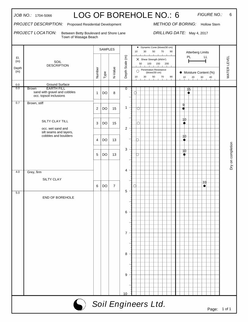
4.2 Earth Fill (Boreholes 4, 6, 7, 8 and 9)
An earth fill was contacted at the ground surface or below the topsoil. It extended
to depths of 0.6 m and 0.7 m below the prevailing ground surface. The fill consists
of sand or silty sand, with gravel, cobbles, rock fragments and occasional topsoil
inclusions.
The obtained ‘N’ values range from 2 to 15, with a median of 8 blows per 30 cm of
penetration, indicating that the fill was loosely placed. Its relative density is non-
uniform and is unsuitable to support any structure sensitive to settlement.
The natural water content values range from 8% to 22%, with a median of 16%,
indicating that the fill is in a moist to wet, generally wet condition, which
corresponds with our sample examinations.
For structural use, the existing earth fill must be subexcavated, inspected, sorted
free of topsoil inclusions and any deleterious material, if detected, and properly
compacted.
One must be aware that the samples retrieved from boreholes 10 cm in diameter
may not be truly representative of the geotechnical and environmental quality of the
fill, and do not indicate whether the topsoil beneath the earth fill was completely
stripped. This should be further assessed by laboratory testing and/or test pits.

Reference No. 1704-S066 6
4.3 Silty Clay Till (All Boreholes) and Silty Clay (Boreholes 2, 3, 5 and 6)
The silty clay till was generally encountered at the upper zone of the stratigraphy.
It consists of a random mixture of soils; the particle sizes range from clay to gravel,
with the clay fraction exerting the dominant influence on its soil properties.
Occasional sand and silt seams and layers were also detected in the clay till mantle.
The till is amorphous and heterogeneous in structure, indicating that it is a glacial
deposit and has generally been reworked by the past glaciation.
At Boreholes 2, 3, 5 and 6, a silty clay deposit was contacted below the silty clay till.
It is laminated with sand and silt seams and layers, showing that it is a glacio
lacustrine deposit.
The obtained ‘N’ values range from 5 to 29, with a median of 11 blows per 30 cm of
penetration, indicating that the consistency of the clay till is firm to very stiff, being
generally stiff, confirming that the till has generally been reworked by the past
glaciation. The consistency of the silty clay is soft to firm, being generally firm as
shown by the ‘N’ values ranging from 3 to 7, with a median of 7 blows per 30 cm.
The Atterberg Limits of 1 representative sample of the clay till, 1 representative
sample of the silty clay, and the natural water content values of all the samples were
determined; the results are plotted on the Borehole Logs and summarized below:
Clay Till Silty Clay
Liquid Limit 43% 46%
Plastic Limit 22% 23%
Natural Water Content 8% to 25% 22% to 33%
(median 11%) (median 24%)
Reference No. 1704-S066 7
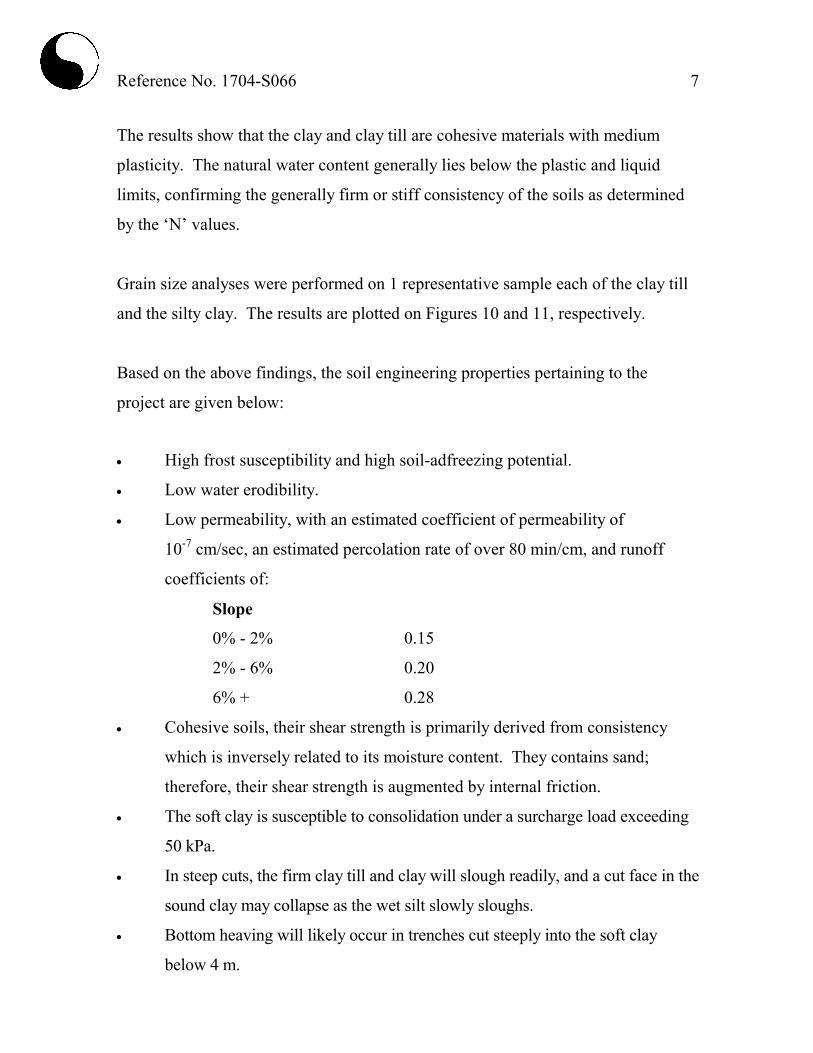
The results show that the clay and clay till are cohesive materials with medium
plasticity. The natural water content generally lies below the plastic and liquid
limits, confirming the generally firm or stiff consistency of the soils as determined
by the ‘N’ values.
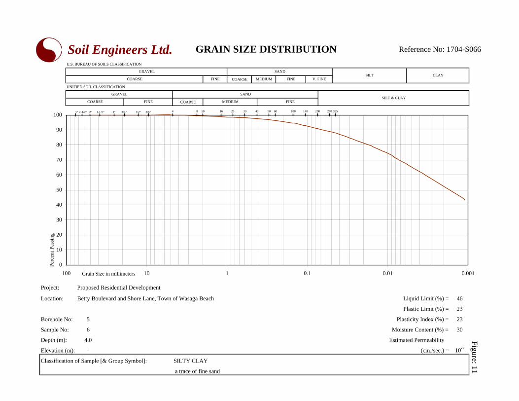
Grain size analyses were performed on 1 representative sample each of the clay till
and the silty clay. The results are plotted on Figures 10 and 11, respectively.
Based on the above findings, the soil engineering properties pertaining to the
project are given below:
• High frost susceptibility and high soil-adfreezing potential.
• Low water erodibility.
• Low permeability, with an estimated coefficient of permeability of
10-7 cm/sec, an estimated percolation rate of over 80 min/cm, and runoff
coefficients of:
Slope
0% - 2% 0.15
2% - 6% 0.20
6% + 0.28
• Cohesive soils, their shear strength is primarily derived from consistency
which is inversely related to its moisture content. They contains sand;
therefore, their shear strength is augmented by internal friction.
• The soft clay is susceptible to consolidation under a surcharge load exceeding
50 kPa.
• In steep cuts, the firm clay till and clay will slough readily, and a cut face in the
sound clay may collapse as the wet silt slowly sloughs.
• Bottom heaving will likely occur in trenches cut steeply into the soft clay
below 4 m.

Reference No. 1704-S066 8
• Poor pavement-supportive materials, with an estimated CBR value of 3%.
• High to moderately high corrosivity to buried metal, with an estimated
electrical resistivity of 2000 to 2500 ohm⋅cm.
4.4 Silty Sand Till/Sandy Silt Till (All Boreholes, except Borehole 6)
The sand till or silt till was encountered at various depths and extends to the
maximum investigated depth at the boreholes where it was encountered. The tills
consist of a random mixture of soil particle sizes ranging from clay to gravel, with
the silt and sand being the dominant fraction. They are heterogeneous in structure,
showing a glacial deposit.
Frequent hard resistance to augering was encountered, showing that appreciable
amounts of cobbles and boulders are embedded in the till deposits
The natural water content value of the samples was determined, and the results are
plotted on the Borehole Logs; the values range from 6% to 20%, with a median of
8%, showing the till is in a moist to wet, generally moist condition.
The obtained ‘N’ values range from 5 blows per 30 cm to 50 blows per 15 cm, with a
median of 35 blows per 30 cm of penetration, showing that its relative density is loose
to very dense, being generally dense.
Grain size analyses were performed on 2 sand till samples and the results are plotted on
Figure 12.
The deduced engineering properties pertaining to the project are given below:
• High frost susceptibility and moderate water erodibility.

Reference No. 1704-S066 9
• Moderately impervious, depending on the clay content, with an estimated
coefficient of permeability of 10-5 to 10
-6 cm/sec, an estimated percolation
rate of about 50 min/cm, and runoff coefficients of:
Slope
0% - 2% 0.11 to 0.15
2% - 6% 0.16 to 0.20
6% + 0.23 to 0.28
• A frictional soils, their shear strength is primarily derived from internal
friction and is augmented by cementation. Therefore, their strength is
density dependent.
• They will be stable in steep cuts; however, under prolonged exposure,
immediate sloughing and sheet collapse will likely occur, particularly where
seepage occurs.
• Fair pavement-supportive materials with an estimated CBR value of 8%.
• Moderately low corrosivity to buried metal, with an estimated electrical
resistivity of 5000 ohm·cm.
4.5 Compaction Characteristics of the Revealed Soils
The obtainable degree of compaction is primarily dependent on the soil moisture
and, to a lesser extent, on the type of compactor used and the effort applied.
As a general guide, the typical water content values of the revealed soils for
Standard Proctor compaction are presented in Table 1.

Reference No. 1704-S066 10
Table 1 - Estimated Water Content for Compaction
Water Content (%) for
Standard Proctor Compaction
Soil Type
Determined
Natural Water
Content (%) 100% (optimum) Range for 95% or +
Earth Fill 8 to 22
(median 16)
11 7 to 16
Silty Clay/Clay Till 8 to 33
(median 24)
22 17 to 26
Silty Sand Till and
Sandy Silt Till 6 to 20
(median 8)
10 6 to 15
Based on the above findings, the on-site material is generally suitable for a 95%
or + Standard Proctor compaction, whereas, the wet material will require aeration in
dry and warm weather prior to structural compaction. The earth fill must be sorted
free of topsoil inclusions and deleterious materials prior to use as structural fill.
The silty clay and tills should be compacted using a heavy-weight, kneading-type
roller. The lifts for compaction should be limited to 20 cm, or to a suitable
thickness as assessed by test strips performed by the equipment which will be used
at the time of construction.
When compacting the cemented till on the dry side of the optimum, the compactive
energy will frequently bridge over the chunks in the soil and be transmitted laterally
in the soil mantle. Therefore, the lifts of these soils must be limited to 20 cm or less
(before compaction). It is difficult to monitor the lifts of backfill placed in deep
trenches; therefore, it is preferable that the compaction of backfill at depths over
1.0 m below the pavement subgrade be carried out on the wet side of the optimum.
This would allow a wider latitude of lift thickness.

Reference No. 1704-S066 11
If the compaction of the soils is carried out with the water content within the range
for 95% Standard Proctor dry density but on the wet side of the optimum, the
surface of the compacted soil mantle will roll under the dynamic compactive load.
This is unsuitable for pavement construction since each component of the pavement
structure is to be placed under dynamic conditions which will induce the rolling
action of the subgrade surface and cause structural failure of the new pavement.
The foundation or bedding of the sewer and slab-on-grade will be placed on a
subgrade which will not be subjected to impact loads. Therefore, the structurally
compacted soil mantle with the water content on the wet side or dry side of the
optimum will provide an adequate subgrade for the construction.
The presence of boulders in the tills will prevent transmission of the compactive
energy into the underlying material to be compacted. If an appreciable amount of
boulders over 15 cm in size is mixed with the material, it must either be sorted or
must not be used for structural backfill and/or construction of engineered fill.

Reference No. 1704-S066 12
5.0 GROUNDWATER CONDITIONS
Groundwater seepage encountered during augering was recorded on the field logs.
The level of groundwater and the occurrence of cave-in were measured upon
completion of the boreholes; the data are plotted on the Borehole Logs and listed in
Table 2.
Table 2 - Groundwater Levels
Soil Colour
Changes
Brown to
Grey
Seepage Encountered
During Augering
Measured
Groundwater/
Cave-In* Level
On Completion BH
No.
Borehole
Depth (m) Depth (m) Depth (m) Amount Depth (m) El. (m)
1 6.6 2.3 1.7 Slight 5.9 -
2 5.0 2.1 2.1 Slight Dry -
3 6.3 4.0 2.2 Slight 5.9 -
4 5.0 2.3 - - Dry -
5 6.6 2.3 4.0 Slight Dry -
6 5.0 4.0 4.6 Slight Dry -
7 6.6 2.3 - - Dry -
8 6.3 1.4 - - Dry -
9 5.0 2.3 - - 4.0 -
Groundwater was detected at depths of 4.0 m and 5.9 m at three of the boreholes;
all other boreholes remained dry upon completion of field work. The groundwater
represents a perched water in wet sand seams. It will fluctuate with the seasons.
The soil colour changes from brown to grey at depths ranging from 1.4 to 4.0 m
below the prevailing ground surface. The brown colour indicates that the soils
have oxidized.

Reference No. 1704-S066 13
In excavations, the groundwater yield is anticipated to be small and limited. It can
be drained to a sump pit and removed by conventional pumping.

Reference No. 1704-S066 14
6.0 DISCUSSION AND RECOMMENDATIONS
The investigation has disclosed that beneath a veneer of topsoil and a layer of earth
fill in places, the site is underlain by strata of firm to very stiff, generally stiff silty
clay till and loose to very dense, generally dense sandy silt till and silty sand till,
with layers of soft to firm, generally firm silty clay.
Groundwater was detected at depths of 4.0 m and 5.9 m at three of the boreholes;
all other boreholes remained dry upon completion of field work. The groundwater
represents a perched water in wet sand seams. It will fluctuate with the seasons.
The geotechnical findings which warrant special consideration are presented below:
1. The existing trees must be removed and the topsoil must be stripped for the
project construction. The topsoil will generate volatile gases under anaerobic
conditions and is unsuitable for engineering applications. Therefore, it should
be placed in the landscaped areas only and should not be buried within the
building envelope, or deeper than 1.2 m below the exterior finished grade of
the project.
2. The earth fill in its present condition is not capable of supporting any
structures susceptible to settlement. It must be upgraded to structural status by
sorting it free of serious topsoil inclusions and deleterious material and by
proper compaction.
3. The sound, natural soils are suitable for normal spread and strip footing
construction. Due to the presence of topsoil and earth fill, the footing subgrade
must be inspected by either a geotechnical engineer, or a geotechnical
technician under the supervision of a geotechnical engineer, to ensure that its
condition is compatible with the design of the foundation.
Reference No. 1704-S066 15
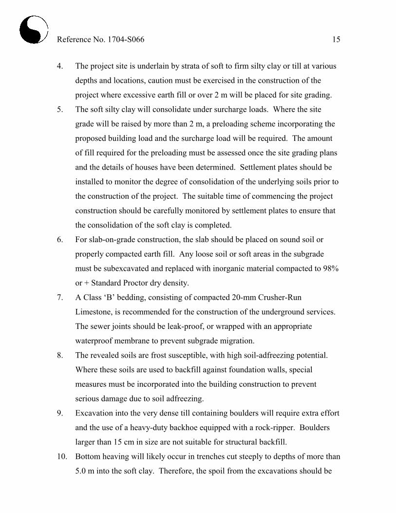
4. The project site is underlain by strata of soft to firm silty clay or till at various
depths and locations, caution must be exercised in the construction of the
project where excessive earth fill or over 2 m will be placed for site grading.
5. The soft silty clay will consolidate under surcharge loads. Where the site
grade will be raised by more than 2 m, a preloading scheme incorporating the
proposed building load and the surcharge load will be required. The amount
of fill required for the preloading must be assessed once the site grading plans
and the details of houses have been determined. Settlement plates should be
installed to monitor the degree of consolidation of the underlying soils prior to
the construction of the project. The suitable time of commencing the project
construction should be carefully monitored by settlement plates to ensure that
the consolidation of the soft clay is completed.
6. For slab-on-grade construction, the slab should be placed on sound soil or
properly compacted earth fill. Any loose soil or soft areas in the subgrade
must be subexcavated and replaced with inorganic material compacted to 98%
or + Standard Proctor dry density.
7. A Class ‘B’ bedding, consisting of compacted 20-mm Crusher-Run
Limestone, is recommended for the construction of the underground services.
The sewer joints should be leak-proof, or wrapped with an appropriate
waterproof membrane to prevent subgrade migration.
8. The revealed soils are frost susceptible, with high soil-adfreezing potential.
Where these soils are used to backfill against foundation walls, special
measures must be incorporated into the building construction to prevent
serious damage due to soil adfreezing.
9. Excavation into the very dense till containing boulders will require extra effort
and the use of a heavy-duty backhoe equipped with a rock-ripper. Boulders
larger than 15 cm in size are not suitable for structural backfill.
10. Bottom heaving will likely occur in trenches cut steeply to depths of more than
5.0 m into the soft clay. Therefore, the spoil from the excavations should be
Reference No. 1704-S066 16
placed at a distance from the edge of the excavation at least equal to 3 times
the depth of the excavation, and the sides should be cut at 1 vertical:
2 or + horizontal.
11. It is advised that the contractor be requested to record the occurrences of soft
clay during trenching. This information can be used to forewarn the house
builders to exercise caution in footing construction.
The recommendations appropriate for the project described in Section 2.0 are
presented herein. One must be aware that the subsurface conditions may vary
between boreholes. Should this become apparent during construction, a
geotechnical engineer must be consulted to determine whether the following
recommendations require revision.
6.1 Foundations
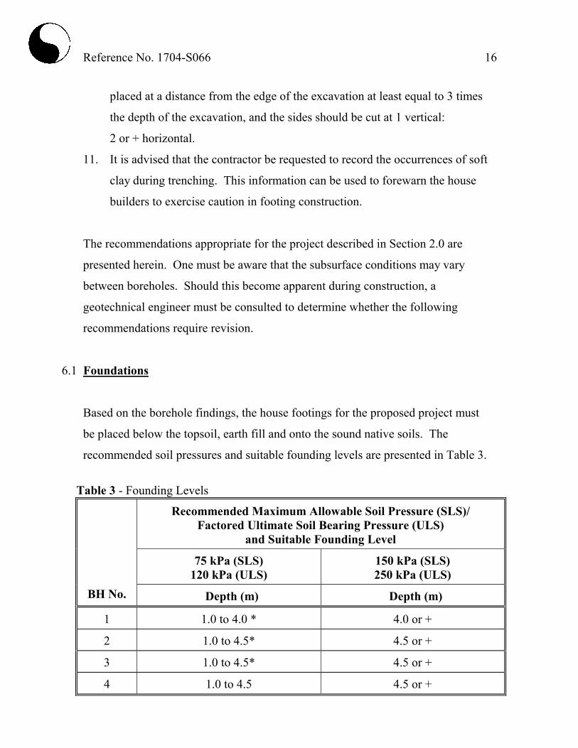
Based on the borehole findings, the house footings for the proposed project must
be placed below the topsoil, earth fill and onto the sound native soils. The
recommended soil pressures and suitable founding levels are presented in Table 3.
Table 3 - Founding Levels
Recommended Maximum Allowable Soil Pressure (SLS)/
Factored Ultimate Soil Bearing Pressure (ULS)
and Suitable Founding Level
75 kPa (SLS)
120 kPa (ULS)
150 kPa (SLS)
250 kPa (ULS)
BH No. Depth (m) Depth (m)
1 1.0 to 4.0 * 4.0 or +
2 1.0 to 4.5* 4.5 or +
3 1.0 to 4.5* 4.5 or +
4 1.0 to 4.5 4.5 or +
Reference No. 1704-S066 17
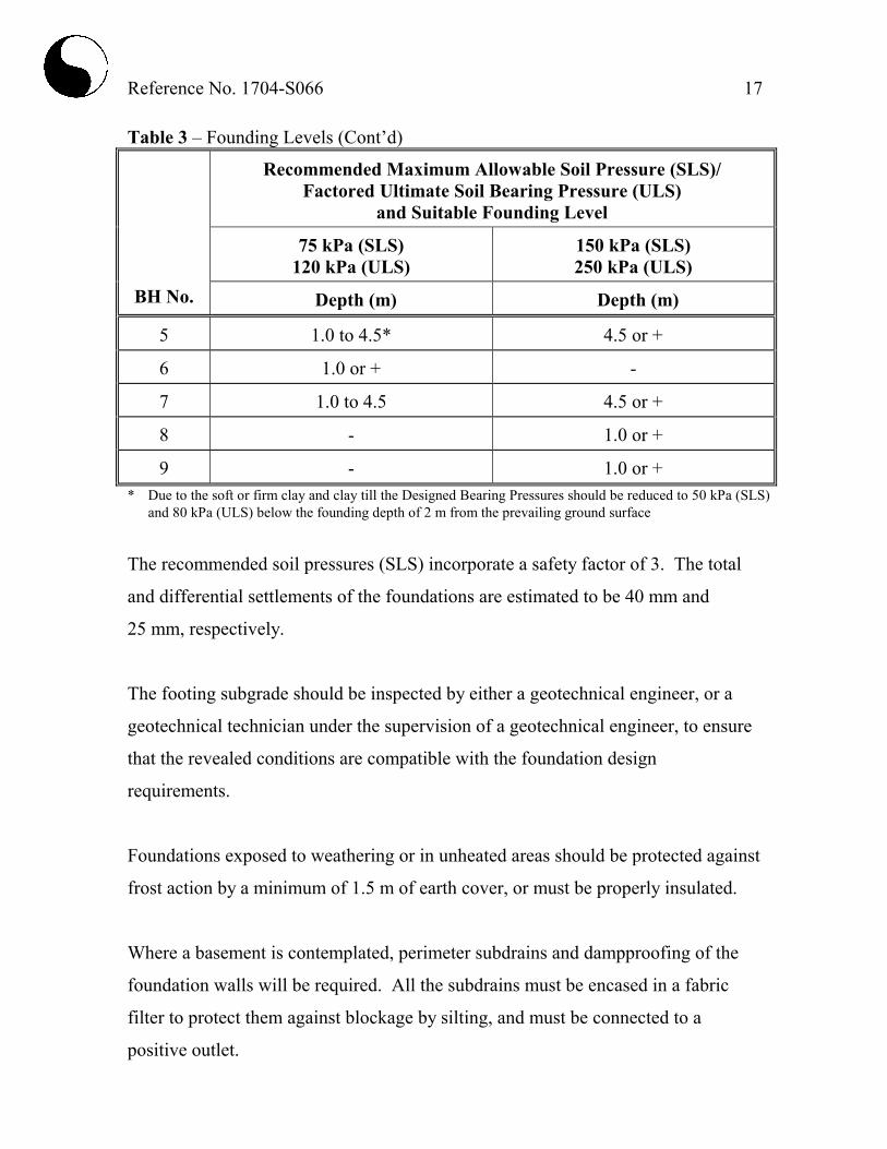
Table 3 – Founding Levels (Cont’d)
Recommended Maximum Allowable Soil Pressure (SLS)/
Factored Ultimate Soil Bearing Pressure (ULS)
and Suitable Founding Level
75 kPa (SLS)
120 kPa (ULS)
150 kPa (SLS)
250 kPa (ULS)
BH No. Depth (m) Depth (m)
5 1.0 to 4.5* 4.5 or +
6 1.0 or + -
7 1.0 to 4.5 4.5 or +
8 - 1.0 or +
9 - 1.0 or +
* Due to the soft or firm clay and clay till the Designed Bearing Pressures should be reduced to 50 kPa (SLS)
and 80 kPa (ULS) below the founding depth of 2 m from the prevailing ground surface
The recommended soil pressures (SLS) incorporate a safety factor of 3. The total
and differential settlements of the foundations are estimated to be 40 mm and
25 mm, respectively.
The footing subgrade should be inspected by either a geotechnical engineer, or a
geotechnical technician under the supervision of a geotechnical engineer, to ensure
that the revealed conditions are compatible with the foundation design
requirements.
Foundations exposed to weathering or in unheated areas should be protected against
frost action by a minimum of 1.5 m of earth cover, or must be properly insulated.
Where a basement is contemplated, perimeter subdrains and dampproofing of the
foundation walls will be required. All the subdrains must be encased in a fabric
filter to protect them against blockage by silting, and must be connected to a
positive outlet.

Reference No. 1704-S066 18
Where soft clay is present, it will consolidate under a surcharge load exceeding
50 kPa. In case the site will be raised by more than 2 m of earth fill, the site should
be pregraded with an engineered fill, and a pre-loading scheme incorporating the
proposed building load and finished grade load should be carried out. While
settlement will typically occur for about 4 to 6 months after placement of the
surcharge fill, the suitable time for commencing the project construction should be
carefully monitored by settlement plates to ensure that the consolidation of the soft
clay is complete. The surcharge load for the preloading program can be determined
when the site grading and the underside of footing for the buildings are available.
The occurring soils are high in frost heave and soil-adfreezing potential. If these
soils are to be used for the foundation backfill, the foundation walls should be
shielded by a polyethylene slip-membrane for protection against soil adfreezing.
The membrane will allow vertical movement of the heaving soil (due to frost)
without imposing structural distress on the foundations. The recommended
measures are schematically illustrated in Diagram 1.
Diagram 1 - Frost Protection Measures (Foundations)
1.2m
Covered with 19-mm Clear StoneSubdrain Encased in Fabric Filter
Slip-Membrane (Closed End Up)
Folded Heavy Polyethylene
1.5 m

Reference No. 1704-S066 19
The necessity to implement the above recommendations should be further assessed
by a geotechnical engineer at the time of construction.
The foundations must meet the requirements specified by the latest Ontario
Building Code, and the buildings must be designed to resist a minimum earthquake
force using Site Classification ‘D’ (stiff soil).
6.2 Engineered Fill
Where earth fill is required to raise the site or where extended footings are
necessary, the engineering requirements for a certifiable fill for road construction,
municipal services, slab-on-grade, and footings designed with a Maximum
Allowable Soil Pressure (SLS) of 75 kPa and a Factored Ultimate Soil Bearing
Pressure (ULS) of 120 kPa, are presented below:
1. The topsoil must be removed. The loose earth fill must be subexcavated. The
subgrade must be inspected and surface proof-rolled.
2. Inorganic soils must be used, and they must be uniformly compacted in lifts
20 cm thick to 98% or + of their maximum Standard Proctor dry density up to
the proposed finished grade. The soil moisture must be properly controlled on
the wet side of the optimum. If the house foundations are to be built soon
after the fill placement, the densification process for the engineered fill must
be increased to 100% of the maximum Standard Proctor compaction.
3. If imported fill is to be used, it should be inorganic soils, free of deleterious
material with environmental issue (contamination). Any potential imported
earth fill from off-site must be reviewed for geotechnical and environmental
quality by the appropriate personnel as authorized by the developer or agency,
before hauling to the site.

Reference No. 1704-S066 20
4. If the engineered fill is to be left over the winter months, adequate earth cover
or equivalent must be provided for protection against frost action.
5. The engineered fill must extend over the entire graded area; the engineered fill
envelope and finished elevations must be clearly and accurately defined in the
field, and must be precisely documented by qualified surveyors. Foundations
partially on engineered fill must be reinforced by two 15-mm steel reinforcing
bars in the footings and upper section of the foundation walls, or be designed
by a structural engineer to properly distribute the stress induced by the abrupt
differential settlement (about 25 mm) between the natural soil and engineered
fill.
6. The engineered fill must not be placed during the period from late November
to early April when freezing ambient temperatures occur either persistently or
intermittently. This is to ensure that the fill is free of frozen soils, ice or snow.
7. Where the fill is to be placed on a bank steeper than 1 vertical:3 horizontal, the
face of the bank must be flattened to 3 + so that it is suitable for safe operation
of the compactor and the required compaction can be obtained.
8. Where the ground is wet due to subsurface water seepage, an appropriate
subdrain scheme must be implemented prior to the fill placement, particularly
if it is to be carried out on sloping ground.
9. The fill operation must be inspected on a full-time basis by a technician under
the direction of a geotechnical engineer.
10. The footing and underground services subgrade must be inspected by the
geotechnical consulting firm that supervised the engineered fill placement.
This is to ensure that the foundations are placed within the engineered fill
envelope, and the integrity of the fill has not been compromised by interim
construction, environmental degradation and/or disturbance by the footing
excavation.
Reference No. 1704-S066 21
11. Any excavation carried out in certified engineered fill must be reported to the
geotechnical consultant who supervised the fill placement in order to
document the locations of excavation and/or to supervise reinstatement of the
excavated areas to engineered fill status. If construction on the engineered fill
does not commence within a period of 2 years from the date of certification,
the condition of the engineered fill must be assessed for re-certification.
12. Despite stringent control in the placement of the engineered fill, variations in
soil type and density may occur in the engineered fill. Therefore, the strip
footings and the upper section of the foundation walls constructed on the
engineered fill may require continuous reinforcement with steel bars,
depending on the uniformity of the soils in the engineered fill and the
thickness of the engineered fill underlying the foundations. Should the
footings and/or walls require reinforcement, the required number and size of
reinforcing bars must be assessed by considering the uniformity as well as the
thickness of the engineered fill beneath the foundations. In sewer
construction, the engineered fill is considered to have the same structural
proficiency as a natural inorganic soil.
13. Due to the presence of soft clay, the engineered fill must be left in place for a
period of time prior to the start of any construction. This must be confirmed
by the installation of settlement plates to ensure that the consolidation of the
very soft to soft clay and clay till is completed prior to the start of the
construction.
6.3 Slab-On-Grade
The subgrade should be inspected and assessed by proof-rolling prior to slab-on-
grade construction. Where loose or soft soil is detected, it should be subexcavated
and replaced with inorganic material uniformly compacted to 98% or + of its
maximum Standard Proctor dry density.
Reference No. 1704-S066 22
Any new material for raising the grade should consist of organic-free soil
compacted to at least 98% of its maximum Standard Proctor dry density.
The slab should be constructed on a granular base 20 cm thick, consisting of
20-mm Crusher-Run Limestone, or equivalent, compacted to its maximum Standard
Proctor dry density.
A Modulus of Subgrade Reaction of 20 MPa/m can be used for the design of the
floor slab. If the subgrade is wet, a vapour barrier must be placed below the
granular base of the floor slab to prevent upfiltration of moisture that may wet the
slab surface.
The ground around the buildings must be graded to direct water away from the
structure to minimize the frost heave phenomenon generally associated with the
disclosed soils.
The requirements for the above measures can be further assessed during
construction.
6.4 Underground Services
The subgrade for the underground services should consist of natural soils or
compacted organic-free earth fill. Where topsoil, earth fill and soft subgrade are
encountered, these materials must be subexcavated and replaced with properly
compacted bedding material.

Reference No. 1704-S066 23
A Class ‘B bedding, consisting of compacted 20-mm Crusher-Run Limestone, is
recommended for the construction of the underground services. The pipe joints
should be leak-proof or wrapped with an appropriate waterproof membrane to
prevent subgrade migration.
Where the subgrade consists of soft soils, it should be subexcavated and replaced by
the bedding material.
In order to prevent pipe floatation when the sewer trench is deluged with water, a
soil cover with a thickness equal to the diameter of the pipe should be in place at all
times after completion of the pipe installation.
Openings to subdrains and catch basins should be shielded with a fabric filter to
prevent blockage by silting.
Since the silty clay has high to moderately high corrosivity to buried metal, the
water main should be protected against corrosion. In determining the mode of
protection, an electrical resistivity of 2000 ohm·cm should be used. This, however,
should be confirmed by testing the soil along the water main alignment at the time
of sewer construction.
6.5 Trench Backfilling
The on-site inorganic soils are suitable for trench backfill. In the zone within 1.0 m
below the pavement subgrade, the backfill should be compacted to at least 98% of
its maximum Standard Proctor dry density with the moisture content 2% to 3% drier
than the optimum. In the lower zone, a 95% or + Standard Proctor compaction is
considered to be adequate; however, the material must be compacted on the wet
side of the optimum.

Reference No. 1704-S066 24
Below the floor slab, the backfill must be compacted to 98% or + of its Standard
Proctor dry density.
In normal underground services construction practice, the problem areas of road
settlement largely occur adjacent to manholes, catch basins, services crossings,
foundation walls and columns, and it is recommended that a sand backfill be used.
Unless compaction of the backfill is carefully performed, the interface of the native
soils and the sand backfill will have to be flooded for a period of several days.
The narrow trenches should be cut at 1 vertical:2 or + horizontal so that the backfill
can be effectively compacted. Otherwise, soil arching will prevent the achievement
of proper compaction. The lift of each backfill layer should either be limited to a
thickness of 20 cm, or the thickness should be determined by test strips.
One must be aware of the possible consequences during trench backfilling and
exercise caution as described below:
• When construction is carried out in freezing winter weather, allowance should
be made for these following conditions. Despite stringent backfill monitoring,
frozen soil layers may inadvertently be mixed with the structural trench
backfill. Should the in situ soils have a water content on the dry side of the
optimum, it would be impossible to wet the soils due to the freezing condition,
rendering difficulties in obtaining uniform and proper compaction.
Furthermore, the freezing condition will prevent flooding of the backfill when
it is required, such as in a narrow vertical trench section, or when the trench
box is removed. The above will invariably cause backfill settlement that may
become evident within 1 to several years, depending on the depth of the trench
which has been backfilled.

Reference No. 1704-S066 25
• In areas where the underground services construction is carried out during
winter months, prolonged exposure of the trench walls will result in frost
heave within the soil mantle of the walls. This may result in some settlement
as the frost recedes, and repair costs will be incurred prior to final surfacing of
the new pavement and the slab-on-grade construction.
• To backfill a deep trench, one must be aware that future settlement is to be
expected, unless the side of the cut is flattened to at least 1 vertical:
1.5 + horizontal, and the lifts of the fill and its moisture content are stringently
controlled; i.e., lifts should be no more than 20 cm (or less if the backfilling
conditions dictate) and uniformly compacted to achieve at least 95% of the
maximum Standard Proctor dry density, with the moisture content on the wet
side of the optimum.
• It is often difficult to achieve uniform compaction of the backfill in the lower
vertical section of a trench which is an open cut or is stabilized by a trench
box, particularly in the sector close to the trench walls or the sides of the box.
These sectors must be backfilled with sand. In a trench stabilized by a trench
box, the void left after the removal of the box will be filled by the backfill. It
is necessary to backfill this sector with sand, and the compacted backfill must
be flooded for 1 day, prior to the placement of the backfill above this sector,
i.e., in the upper sloped trench section. This measure is necessary in order to
prevent consolidation of inadvertent voids and loose backfill which will
compromise the compaction of the backfill in the upper section. In areas
where groundwater movement is expected in the sand fill mantle, seepage
collars should be provided.

Reference No. 1704-S066 26
6.6 Garages, Driveways and Interlocking Stone Pavement
Due to the high frost susceptibility of the underlying soils, heaving of the pavement
is expected to occur during the cold weather.
The driveways at the entrances to the garages should be backfilled with non-frost-
susceptible granular material, with a frost taper at a slope of 1 vertical:1 horizontal.
Interlocking stone pavement in areas which are sensitive to frost-induced ground
movement, such as entrances, must be constructed on a free-draining, non-frost-
susceptible granular material such as Granular ‘B’. It must extend to 0.3 to 1.2 m
below the slab or pavement surface, depending on the tolerance for ground
movement, and be provided with positive drainage such as weeper subdrains
connected to manholes or catch basins. Alternatively, the sidewalks and the
interlocking stone pavement should be properly insulated with 50-mm Styrofoam,
or equivalent, as approved by a geotechnical engineer.
The grading around the structures must be sloped such that surface runoff is
directed away from the structures.
6.7 Pavement Design
Based on the borehole findings, the recommended pavement design for local roads is
presented in Table 4.

Reference No. 1704-S066 27
Table 4 - Pavement Design
Course Thickness (mm) OPS Specifications
Asphalt Surface 40 HL-3
Asphalt Binder
Local
Collector
50
75
HL-4
Granular Base 150 Granular ‘A’ or equivalent
Granular Sub-base 300 Granular ‘B’ or equivalent
In preparation of the subgrade, the fine-graded surface should be proof-rolled; any
soft subgrade, organics and deleterious materials within 1.0 m below the underside
of the granular sub-base should be subexcavated and replaced by properly
compacted organic-free earth fill.
All the granular bases should be compacted to their maximum Standard Proctor dry
density.
In the zone within 1.0 m below the pavement subgrade, the backfill should be
compacted to at least 98% of its maximum Standard Proctor dry density, with the
water content 2% to 3% drier than the optimum. In the lower zone, a 95% or +
Standard Proctor compaction is considered adequate.
The road subgrade will suffer a strength regression if water is allowed to infiltrate
prior to paving. The following measures should therefore be incorporated in the
construction procedures and road design:
• If the road construction does not immediately follow the trench backfilling,
the subgrade should be properly crowned and smooth-rolled to allow interim
precipitation to be properly drained.
Reference No. 1704-S066 28
• Lot areas adjacent to the roads should be properly graded to prevent the
ponding of large amounts of water during the interim construction period.
• Curb subdrains will be required. The subdrains should consist of filter-
sleeved weepers to prevent blockage by silting.
• If the roads are to be constructed during the wet seasons and extensively soft
subgrade occurs, the granular sub-base may require thickening. This can be
assessed during construction.
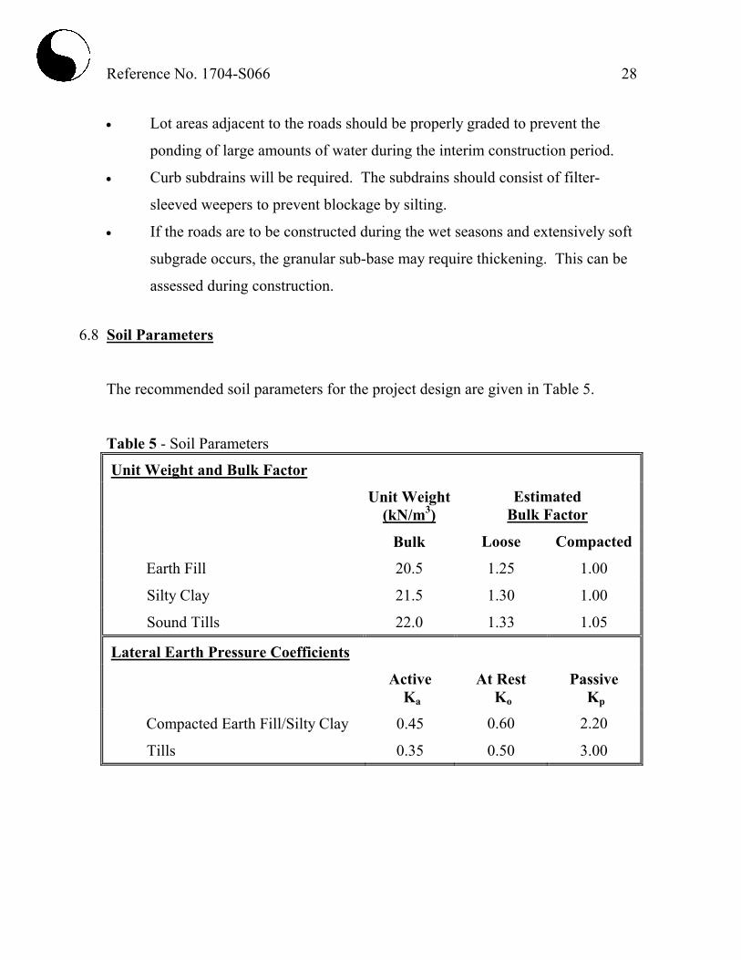
6.8 Soil Parameters
The recommended soil parameters for the project design are given in Table 5.
Table 5 - Soil Parameters
Unit Weight and Bulk Factor
Unit Weight
(kN/m3)
Estimated
Bulk Factor
Bulk Loose Compacted
Earth Fill 20.5 1.25 1.00
Silty Clay 21.5 1.30 1.00
Sound Tills 22.0 1.33 1.05
Lateral Earth Pressure Coefficients
Active
Ka
At Rest
Ko
Passive
Kp
Compacted Earth Fill/Silty Clay 0.45 0.60 2.20
Tills 0.35 0.50 3.00
Reference No. 1704-S066 29
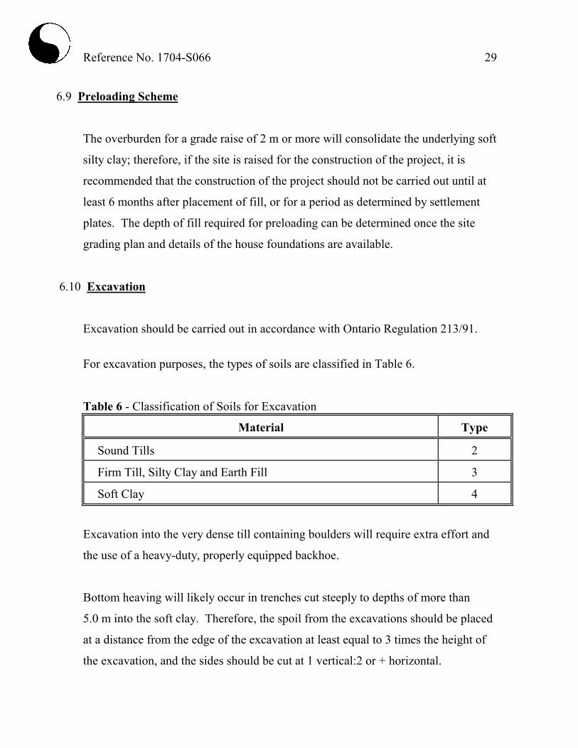
6.9 Preloading Scheme
The overburden for a grade raise of 2 m or more will consolidate the underlying soft
silty clay; therefore, if the site is raised for the construction of the project, it is
recommended that the construction of the project should not be carried out until at
least 6 months after placement of fill, or for a period as determined by settlement
plates. The depth of fill required for preloading can be determined once the site
grading plan and details of the house foundations are available.
6.10 Excavation
Excavation should be carried out in accordance with Ontario Regulation 213/91.
For excavation purposes, the types of soils are classified in Table 6.
Table 6 - Classification of Soils for Excavation
Material Type
Sound Tills 2
Firm Till, Silty Clay and Earth Fill 3
Soft Clay 4
Excavation into the very dense till containing boulders will require extra effort and
the use of a heavy-duty, properly equipped backhoe.
Bottom heaving will likely occur in trenches cut steeply to depths of more than
5.0 m into the soft clay. Therefore, the spoil from the excavations should be placed
at a distance from the edge of the excavation at least equal to 3 times the height of
the excavation, and the sides should be cut at 1 vertical:2 or + horizontal.
Reference No. 1704-S066 30
The groundwater yield in excavations will be small and limited and can be
controlled by pumping from sumps.
Prospective contractors must be asked to assess the in situ subsurface conditions for
soil cuts by digging test pits to at least 0.5 m below the intended bottom of
excavation. These test pits should be allowed to remain open for a period of at
least 4 hours to assess the trenching conditions.


LIST OF ABBREVIATIONS AND DESCRIPTION OF TERMS
The abbreviations and terms commonly employed on the borehole logs and figures, and in the text of the report, are as follows: SAMPLE TYPES
AS Auger sample CS Chunk sample DO Drive open (split spoon) DS Denison type sample FS Foil sample RC Rock core (with size and percentage
recovery) ST Slotted tube TO Thin-walled, open TP Thin-walled, piston WS Wash sample PENETRATION RESISTANCE
Dynamic Cone Penetration Resistance:
A continuous profile showing the number of blows for each foot of penetration of a 2-inch diameter, 90° point cone driven by a 140-pound hammer falling 30 inches. Plotted as ‘ • ’
Standard Penetration Resistance or ‘N’ Value:
The number of blows of a 140-pound hammer falling 30 inches required to advance a 2-inch O.D. drive open sampler one foot into undisturbed soil. Plotted as ‘ ’
WH Sampler advanced by static weight PH Sampler advanced by hydraulic pressure PM Sampler advanced by manual pressure NP No penetration
SOIL DESCRIPTION
Cohesionless Soils:
‘N’ (blows/ft) Relative Density
0 to 4 very loose 4 to 10 loose
10 to 30 compact 30 to 50 dense
over 50
very dense
Cohesive Soils:
Undrained Shear Strength (ksf) ‘N’ (blows/ft) Consistency
less than 0.25 0 to 2 very soft 0.25 to 0.50 2 to 4 soft 0.50 to 1.0 4 to 8 firm
1.0 to 2.0 8 to 16 stiff 2.0 to 4.0 16 to 32 very stiff
over 4.0 over 32 hard
Method of Determination of Undrained Shear Strength of Cohesive Soils:
x 0.0 Field vane test in borehole; the number denotes the sensitivity to remoulding
Laboratory vane test
Compression test in laboratory
For a saturated cohesive soil, the undrained shear strength is taken as one half of the undrained compressive strength
METRIC CONVERSION FACTORS 1 ft = 0.3048 metres 1 inch = 25.4 mm 1lb = 0.454 kg 1ksf = 47.88 kPa

0.0
0.3
4.0
6.6
END OF BOREHOLE
30 cm TOPSOIL
Brown, firm to stiff
SILTY CLAY TILL
occ. wet sand and silt seams and layers, cobbles and boulders
Grey, dense to very dense
SILTY SAND TILL
occ. wet sand and silt seams and layers, cobbles and boulders
browngrey
9
8
7
5
5
70
35
DO
DO
DO
DO
DO
DO
DO
1A
1B
2
3
4
5
6
7
10
9
8
7
6
5
4
3
2
1
0 34
16
21
22
21
6
7
W.L
. @ a
dep
th o
f 5.9
m o
n co
mpl
etio
n
1LOG OF BOREHOLE NO.:1704-S066JOB NO.:
Proposed Residential DevelopmentPROJECT DESCRIPTION:
Between Betty Boulevard and Shore Lane Town of Wasaga Beach
PROJECT LOCATION:
1FIGURE NO.:
Hollow StemMETHOD OF BORING:
May 8, 2017DRILLING DATE:
0.0 Ground Surface
El.(m)
Depth(m)
SOILDESCRIPTION
SAMPLES
Num
ber
Type
N-V
alue
Dep
th S
cale
(m)
Atterberg LimitsPL LL
WA
TER
LE
VE
L
Dynamic Cone (blows/30 cm)
9070503010
Penetration Resistance(blows/30 cm)
9070503010
Shear Strength (kN/m2)
20015010050
Moisture Content (%)40302010
Soil Engineers Ltd.1 of 1Page:

0.0
0.4
2.1
3.0
5.0
END OF BOREHOLE
36 cm TOPSOIL
Brown, stiff
SILTY CLAY TILL
occ. wet sand and silt seams and layers, cobbles and boulders
Grey, firm
SILTY CLAY
Grey, loose to dense
SANDY SILT TILL occ. wet sand and silt seams and layers, cobbles and boulders
9
9
10
5
5
49
DO
DO
DO
DO
AS
DO
DO
1A
1B
2
3
4
5A
5B
6
10
9
8
7
6
5
4
3
2
1
0 2311
14
17
24
23
20
8
Dry
on
com
plet
ion
2LOG OF BOREHOLE NO.:1704-S066JOB NO.:
Proposed Residential DevelopmentPROJECT DESCRIPTION:
Between Betty Boulevard and Shore Lane Town of Wasaga Beach
PROJECT LOCATION:
2FIGURE NO.:
Hollow StemMETHOD OF BORING:
May 8, 2017DRILLING DATE:
0.0 Ground Surface
El.(m)
Depth(m)
SOILDESCRIPTION
SAMPLES
Num
ber
Type
N-V
alue
Dep
th S
cale
(m)
Atterberg LimitsPL LL
WA
TER
LE
VE
L
Dynamic Cone (blows/30 cm)
9070503010
Penetration Resistance(blows/30 cm)
9070503010
Shear Strength (kN/m2)
20015010050
Moisture Content (%)40302010
Soil Engineers Ltd.1 of 1Page:

0.0
2.9
4.0
6.3
END OF BOREHOLE
10 cm TOPSOIL
Brown, firm to very stiff
SILTY CLAY TILL
occ. wet sand and silt seams and layers, cobbles and boulders
Brown, soft
SILTY CLAY
Grey, very dense
SILTY SAND TILL occ. wet sand and silt seams and layers, cobbles and boulders
29
14
17
8
3
97
50/15
DO
DO
DO
DO
DO
DO
DO
1A
1B
2
3
4
5
6
7
10
9
8
7
6
5
4
3
2
1
011
15
12
25
22
8
8
94
W.L
. @ a
dep
th o
f 5.9
m o
n co
mpl
etio
n
3LOG OF BOREHOLE NO.:1704-S066JOB NO.:
Proposed Residential DevelopmentPROJECT DESCRIPTION:
Between Betty Boulevard and Shore Lane Town of Wasaga Beach
PROJECT LOCATION:
3FIGURE NO.:
Hollow StemMETHOD OF BORING:
May 8, 2017DRILLING DATE:
0.0 Ground Surface
El.(m)
Depth(m)
SOILDESCRIPTION
SAMPLES
Num
ber
Type
N-V
alue
Dep
th S
cale
(m)
Atterberg LimitsPL LL
WA
TER
LE
VE
L
Dynamic Cone (blows/30 cm)
9070503010
Penetration Resistance(blows/30 cm)
9070503010
Shear Strength (kN/m2)
20015010050
Moisture Content (%)40302010
Soil Engineers Ltd.1 of 1Page:

0.0
0.6
1.4
4.0
5.0
END OF BOREHOLE
36 cm TOPSOIL
Brown EARTH FILL silty sandBrown, compact
SILTY SAND TILL
Firm to very stiff
SILTY CLAY TILL
occ. wet sand and silt seams and layers, cobbles and boulders
Grey, compact SILTY SAND TILL
browngrey
2
17
21
16
8
22
DO
DO
DO
DO
DO
DO
1A
1B
2
3
4
5
6A6B
10
9
8
7
6
5
4
3
2
1
0 2117
9
9
8
9
988
Dry
on
com
plet
ion
4LOG OF BOREHOLE NO.:1704-S066JOB NO.:
Proposed Residential DevelopmentPROJECT DESCRIPTION:
Between Betty Boulevard and Shore Lane Town of Wasaga Beach
PROJECT LOCATION:
4FIGURE NO.:
Hollow StemMETHOD OF BORING:
May 8, 2017DRILLING DATE:
0.0 Ground Surface
El.(m)
Depth(m)
SOILDESCRIPTION
SAMPLES
Num
ber
Type
N-V
alue
Dep
th S
cale
(m)
Atterberg LimitsPL LL
WA
TER
LE
VE
L
Dynamic Cone (blows/30 cm)
9070503010
Penetration Resistance(blows/30 cm)
9070503010
Shear Strength (kN/m2)
20015010050
Moisture Content (%)40302010
Soil Engineers Ltd.1 of 1Page:
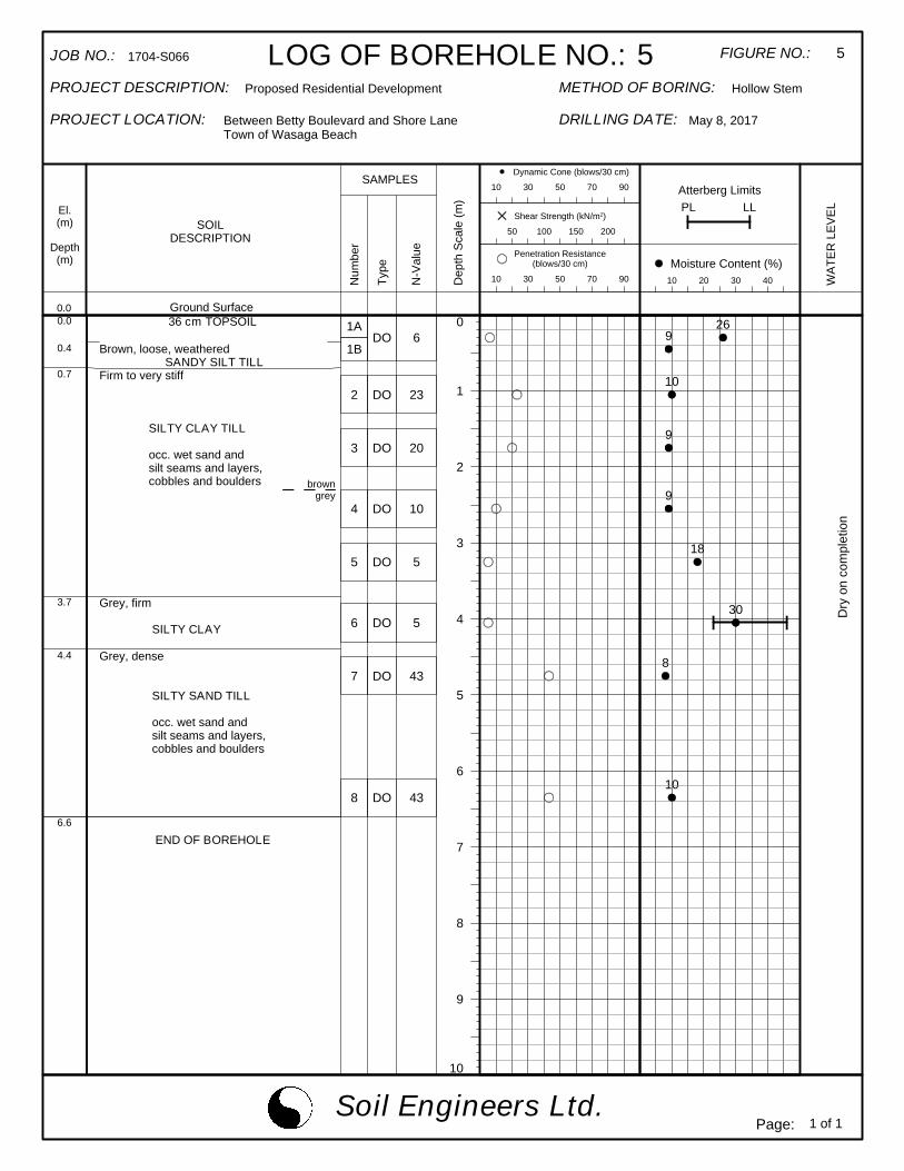
0.0
0.4
0.7
3.7
4.4
6.6
END OF BOREHOLE
36 cm TOPSOIL
Brown, loose, weathered SANDY SILT TILLFirm to very stiff
SILTY CLAY TILL
occ. wet sand and silt seams and layers, cobbles and boulders
Grey, firm
SILTY CLAY
Grey, dense
SILTY SAND TILL occ. wet sand and silt seams and layers, cobbles and boulders
browngrey
6
23
20
10
5
5
43
43
DO
DO
DO
DO
DO
DO
DO
DO
1A
1B
2
3
4
5
6
7
8
10
9
8
7
6
5
4
3
2
1
0 269
10
9
9
18
30
8
10
Dry
on
com
plet
ion
5LOG OF BOREHOLE NO.:1704-S066JOB NO.:
Proposed Residential DevelopmentPROJECT DESCRIPTION:
Between Betty Boulevard and Shore Lane Town of Wasaga Beach
PROJECT LOCATION:
5FIGURE NO.:
Hollow StemMETHOD OF BORING:
May 8, 2017DRILLING DATE:
0.0 Ground Surface
El.(m)
Depth(m)
SOILDESCRIPTION
SAMPLES
Num
ber
Type
N-V
alue
Dep
th S
cale
(m)
Atterberg LimitsPL LL
WA
TER
LE
VE
L
Dynamic Cone (blows/30 cm)
9070503010
Penetration Resistance(blows/30 cm)
9070503010
Shear Strength (kN/m2)
20015010050
Moisture Content (%)40302010
Soil Engineers Ltd.1 of 1Page:
0.0
0.7
4.0
5.0
END OF BOREHOLE
Brown EARTH FILL sand with gravel and cobbles occ. topsoil inclusions
Brown, stiff
SILTY CLAY TILL
occ. wet sand and silt seams and layers, cobbles and boulders
Grey, firm
SILTY CLAY
8
15
15
13
13
7
DO
DO
DO
DO
DO
DO
1
2
3
4
5
6
10
9
8
7
6
5
4
3
2
1
0 15
9
10
10
10
33
Dry
on
com
plet
ion
6LOG OF BOREHOLE NO.:1704-S066JOB NO.:
Proposed Residential DevelopmentPROJECT DESCRIPTION:
Between Betty Boulevard and Shore Lane Town of Wasaga Beach
PROJECT LOCATION:
6FIGURE NO.:
Hollow StemMETHOD OF BORING:
May 4, 2017DRILLING DATE:
0.0 Ground Surface
El.(m)
Depth(m)
SOILDESCRIPTION
SAMPLES
Num
ber
Type
N-V
alue
Dep
th S
cale
(m)
Atterberg LimitsPL LL
WA
TER
LE
VE
L
Dynamic Cone (blows/30 cm)
9070503010
Penetration Resistance(blows/30 cm)
9070503010
Shear Strength (kN/m2)
20015010050
Moisture Content (%)40302010
Soil Engineers Ltd.1 of 1Page:

0.0
0.7
4.0
6.6
END OF BOREHOLE
30 cm TOPSOIL
Brown EARTH FILL sand with gravel and cobblesFirm to stiff
SILTY CLAY TILL
occ. wet sand and silt seams and layers, cobbles and boulders
Grey, dense to very dense
SILTY SAND TILL
occ. wet sand and silt seams and layers, cobbles and boulders
browngrey
5
13
11
11
8
33
75+
DO
DO
DO
DO
DO
DO
DO
1A
1B
2
3
4
5
6
7
10
9
8
7
6
5
4
3
2
1
0 3022
10
12
11
17
8
7
Dry
on
com
plet
ion
7LOG OF BOREHOLE NO.:1704-S066JOB NO.:
Proposed Residential DevelopmentPROJECT DESCRIPTION:
Between Betty Boulevard and Shore Lane Town of Wasaga Beach
PROJECT LOCATION:
7FIGURE NO.:
Hollow StemMETHOD OF BORING:
May 8, 2017DRILLING DATE:
0.0 Ground Surface
El.(m)
Depth(m)
SOILDESCRIPTION
SAMPLES
Num
ber
Type
N-V
alue
Dep
th S
cale
(m)
Atterberg LimitsPL LL
WA
TER
LE
VE
L
Dynamic Cone (blows/30 cm)
9070503010
Penetration Resistance(blows/30 cm)
9070503010
Shear Strength (kN/m2)
20015010050
Moisture Content (%)40302010
Soil Engineers Ltd.1 of 1Page:

0.0
0.7
1.4
6.3
END OF BOREHOLE
Brown EARTH FILL sand with gravel, rock fragments occ. topsoil inclusions
Brown, stiff
SILTY CLAY TILL
Grey, compact to very dense
SANDY SILT TILL
occ. wet sand and silt seams and layers, cobbles and boulders
11
12
16
26
36
50/15
DO
DO
DO
DO
DO
DO
1
2
3
4
5
6
7
10
9
8
7
6
5
4
3
2
1
0 8
12
9
8
77
Dry
on
com
plet
ion
8LOG OF BOREHOLE NO.:1704-S066JOB NO.:
Proposed Residential DevelopmentPROJECT DESCRIPTION:
Between Betty Boulevard and Shore Lane Town of Wasaga Beach
PROJECT LOCATION:
8FIGURE NO.:
Hollow StemMETHOD OF BORING:
May 4, 2017DRILLING DATE:
0.0 Ground Surface
El.(m)
Depth(m)
SOILDESCRIPTION
SAMPLES
Num
ber
Type
N-V
alue
Dep
th S
cale
(m)
Atterberg LimitsPL LL
WA
TER
LE
VE
L
Dynamic Cone (blows/30 cm)
9070503010
Penetration Resistance(blows/30 cm)
9070503010
Shear Strength (kN/m2)
20015010050
Moisture Content (%)40302010
Soil Engineers Ltd.1 of 1Page:

0.00.1
0.7
2.9
5.0
END OF BOREHOLE
10 cm TOPSOILBrown EARTH FILL sand with gravel and cobblesStiff
SILTY CLAY TILL occ. wet sand and silt seams and layers, cobbles and boulders
Grey, compact
SILTY SAND TILL occ. wet sand and silt seams and layers, cobbles and boulders
browngrey
15
12
13
10
20
25
DO
AS
DO
DO
DO
DO
DO
1A
1B
2
3
4
5
6
10
9
8
7
6
5
4
3
2
1
016
11
11
14
8
9
65
W.L
. @ a
dep
th o
f 4.0
m o
n co
mpl
etio
n
9LOG OF BOREHOLE NO.:1704-S066JOB NO.:
Proposed Residential DevelopmentPROJECT DESCRIPTION:
Between Betty Boulevard and Shore Lane Town of Wasaga Beach
PROJECT LOCATION:
9FIGURE NO.:
Hollow StemMETHOD OF BORING:
May 4, 2017DRILLING DATE:
0.0 Ground Surface
El.(m)
Depth(m)
SOILDESCRIPTION
SAMPLES
Num
ber
Type
N-V
alue
Dep
th S
cale
(m)
Atterberg LimitsPL LL
WA
TER
LE
VE
L
Dynamic Cone (blows/30 cm)
9070503010
Penetration Resistance(blows/30 cm)
9070503010
Shear Strength (kN/m2)
20015010050
Moisture Content (%)40302010
Soil Engineers Ltd.1 of 1Page:

Soil Engineers Ltd. Reference No: 1704-S066
U.S. BUREAU OF SOILS CLASSIFICATION
COARSE
UNIFIED SOIL CLASSIFICATION
COARSE
Project: Proposed Residential Development
Location: Betty Boulevard and Shore Lane, Town of Wasaga Beach Liquid Limit (%) = 43
Plastic Limit (%) = 22
Borehole No: 1 Plasticity Index (%) = 21
Sample No: 3 Moisture Content (%) = 21
Depth (m): 1.7 Estimated Permeability
Elevation (m): - (cm./sec.) = 10-7
Classification of Sample [& Group Symbol]: SILTY CLAY TILL
some sand, a trace of gravel
SILT & CLAY
Figure: 10
COARSE
MEDIUM
FINE
CLAY
SAND
MEDIUMFINE
GRAVEL
GRAIN SIZE DISTRIBUTION
SAND
V. FINE
GRAVELSILT
COARSE FINEFINE
3" 2-1/2" 2" 1-1/2" 1" 3/4" 1/2" 3/8" 4 8 10 16 20 30 40 50 60 100 140 200 270 325
0
10
20
30
40
50
60
70
80
90
100
0.0010.010.1110100 Grain Size in millimeters
Perc
ent P
assi
ng
Soil Engineers Ltd. Reference No: 1704-S066
U.S. BUREAU OF SOILS CLASSIFICATION
COARSE
UNIFIED SOIL CLASSIFICATION
COARSE
Project: Proposed Residential Development
Location: Betty Boulevard and Shore Lane, Town of Wasaga Beach Liquid Limit (%) = 46
Plastic Limit (%) = 23
Borehole No: 5 Plasticity Index (%) = 23
Sample No: 6 Moisture Content (%) = 30
Depth (m): 4.0 Estimated Permeability
Elevation (m): - (cm./sec.) = 10-7
Classification of Sample [& Group Symbol]: SILTY CLAY
a trace of fine sand
SILT & CLAY
Figure: 11
COARSE
MEDIUM
FINE
CLAY
SAND
MEDIUMFINE
GRAVEL
GRAIN SIZE DISTRIBUTION
SAND
V. FINE
GRAVELSILT
COARSE FINEFINE
3" 2-1/2" 2" 1-1/2" 1" 3/4" 1/2" 3/8" 4 8 10 16 20 30 40 50 60 100 140 200 270 325
0
10
20
30
40
50
60
70
80
90
100
0.0010.010.1110100 Grain Size in millimeters
Perc
ent P
assi
ng

Reference No: 1704-S066
U.S. BUREAU OF SOILS CLASSIFICATION
COARSE
UNIFIED SOIL CLASSIFICATION
COARSE
Project: Proposed Residential Development BH./Sa. 4/2 7/6Location: Betty Boulevard and Shore Lane, Town of Wasaga Beach Liquid Limit (%) = - -
Plastic Limit (%) = - -Borehole No: 4 7 Plasticity Index (%) = - -Sample No: 2 6 Moisture Content (%) = 9 8Depth (m): 1.1 4.7 Estimated Permeability Elevation (m): - - (cm./sec.) = 10-6 10-5
Classification of Sample [& Group Symbol]: SILTY SAND TILLsome gravel, a trace to some clay
SILT & CLAY
Figure: 12
COARSE
MEDIUM
FINE
CLAY
SAND
MEDIUMFINE
GRAVEL
GRAIN SIZE DISTRIBUTION
SAND
V. FINE
GRAVELSILT
COARSE FINEFINE
3" 2-1/2" 2" 1-1/2" 1" 3/4" 1/2" 3/8" 4 8 10 16 20 30 40 50 60 100 140 200 270 325
0
10
20
30
40
50
60
70
80
90
100
0.0010.010.1110100 Grain Size in millimeters
Perc
ent P
assi
ng
BH.7/Sa.6
BH.4/Sa.2


7
6
5
4
3
2
1
0
7
6
5
4
3
2
1
0
De
pth
(m
)
9
8
7
5
5
70
35
9
9
10
5
5
49
29
14
17
8
3
97
50/15
2
17
21
16
8
22
6
23
20
10
5
5
43
43
8
15
15
13
13
7
5
13
11
11
8
33
75+
11
12
16
26
36
50/15
15
12
13
10
20
25
Soil Engineers Ltd.CONSULTING ENGINEERS
GEOTECHNICAL | ENVIRONMENTAL | HYDROGEOLOGICAL | BUILDING SCIENCE
SUBSURFACE PROFILE
DRAWING NO. 2
SCALE: AS SHOWN
JOB NO.: 1704-S066
REPORT DATE: June 2017
PROJECT DESCRIPTION: Proposed Residential Development
PROJECT LOCATION: Between Betty Boulevard and Shore LaneTown of Wasaga Beach
LEGEND
TOPSOIL
FILL
SILTY SAND TILL
SANDY SILT TILL
SILTY CLAY SILTY CLAY TILL
1
0
2
0
3
0
4
0
5
0
6
0
7
0
8
0
9
0