A Practical NVIS Antenna for Emergency or Temporary...
12
A Practical NVIS Antenna for Emergency or Temporary Communications WP-NVIS Rev. 2a © DX Engineering 2012 P.O. Box 1491 ∙ Akron, OH 44309-1491 Phone: (800) 777-0703 ∙ Tech Support and International: (330) 572-3200 Fax: (330) 572-3279 ∙ E-mail: [email protected]
Transcript of A Practical NVIS Antenna for Emergency or Temporary...
A Practical NVIS Antenna
for Emergency or Temporary
Communications
WP-NVIS Rev. 2a
© DX Engineering 2012
P.O. Box 1491 ∙ Akron, OH 44309-1491
Phone: (800) 777-0703 ∙ Tech Support and International: (330) 572-3200
Fax: (330) 572-3279 ∙ E-mail: [email protected]

- 1 -
WARNING!
INSTALLATION OF ANY ANTENNA NEAR POWER LINES IS DANGEROUS
Warning: Do not locate the antenna near overhead power lines or other electric light or power
circuits, or where it can come into contact with such circuits. When installing the antenna, take
extreme care not to come into contact with such circuits, because they may cause serious injury or
death.
Overhead Power Line Safety Before you begin working, check carefully for overhead power lines in the area you will be
working. Don't assume that wires are telephone or cable lines: check with your electric utility for
advice. Although overhead power lines may appear to be insulated, often these coverings are
intended only to protect metal wires from weather conditions and may not protect you from electric
shock
Keep your distance! Remember the 10-foot rule: When carrying and using ladders and other long
tools, keep them at least 10 feet away from all overhead lines - including any lines from the power
pole to your home.
NVIS
Near Vertical Incidence Skywave (NVIS) is a propagation mode which uses high angle radiation to
send signals almost straight up to be reflected back to Earth for very effective short to medium
distance communications. This mode of
operation makes it ideal for in-state
communications during disasters or other
emergency situations. The military has used
NVIS techniques for decades to provide short
haul communication with other units on the
ground.
NVIS only works at frequencies from 2 MHz
to 10 MHz. The signal must penetrate the D
layer of the ionosphere, and bounce off the F
layer. Lower-frequency signals will not
penetrate the D layer; higher frequencies will
not bounce off the F layer at these sharp
angles and just goes out into space. Remember the Maximum Useable Frequency, or MUF? So, for
amateur radio operators, we're looking at 40 and 80 meters primarily for NVIS use.
- 2 -
A good NVIS antenna will not work well at DX distances. Antenna gain is a zero sum game. There
is a fixed amount of energy radiating. If we push it all out in one direction (the near-vertical angles),
we have to take it away from another direction (the low DX angles).
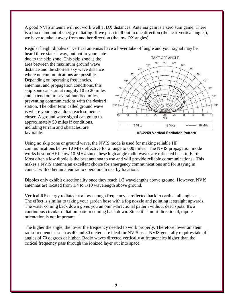
Regular height dipoles or vertical antennas have a lower take off angle and your signal may be
heard three states away, but not in your state
due to the skip zone. This skip zone is the
area between the maximum ground wave
distance and the shortest sky wave distance
where no communications are possible.
Depending on operating frequencies,
antennas, and propagation conditions, this
skip zone can start at roughly 10 to 20 miles
and extend out to several hundred miles,
preventing communications with the desired
station. The other term called ground wave
is where your signal does reach someone
closer. A ground wave signal can go up to
approximately 50 miles if conditions,
including terrain and obstacles, are
favorable.
Using no skip zone or ground wave, the NVIS mode is used for making reliable HF
communications below 10 MHz effective for a range to 600 miles. The NVIS propagation mode
works best on HF below 10 MHz since these high angle radio waves are reflected back to Earth.
Most often a low dipole is the best antenna to use and will provide reliable communications. This
makes a NVIS antenna an excellent choice for emergency communications and for staying in
contact with other amateur radio operators in nearby locations.
Dipoles only exhibit directionality once they reach 1/2 wavelengths above ground. However, NVIS
antennas are located from 1/4 to 1/10 wavelength above ground.
Vertical RF energy radiated at a low enough frequency is reflected back to earth at all angles.
The effect is similar to taking your garden hose with a fog nozzle and pointing it straight upwards.
The water coming back down gives you an omni-directional pattern without dead spots. It's a
continuous circular radiation pattern coming back down. Since it is omni-directional, dipole
orientation is not important.
The higher the angle, the lower the frequency needed to work properly. Therefore lower amateur
radio frequencies such as 40 and 80 meters are ideal for NVIS use. NVIS generally requires takeoff
angles of 70 degrees or higher. Radio waves directed vertically at frequencies higher than the
critical frequency pass through the ionized layer out into space.

- 3 -
The military uses a dual band NVIS antenna known as the AS-2259/GR. It consists of two crossed
inverted "V" dipoles positioned at right angles to each other and is supported at the center by a 15-
foot mast. The antenna was designed for military use from 2 to 10 MHz (some references say 2 to
30 MHz). The dual dipole wires do the job of providing guying support for the mast.
Military AS-2259/GR
There are a number of different NVIS antenna plans on the internet that can be adopted to amateur
radio use. Many hams have modified those plans to operate on the bands they have chosen.
Although originally made for military use, this particular design was found to work on the 80 and
40 meter amateur bands using a good tuner without modifications for the Ohio State Parks On The
Air contest. This design was chosen because of the simplicity, ease of construction and operation.
Let's Build One!
The NVIS antenna described is based on the proven information from the military AS-
2259/GR antenna. It will provide excellent short range communications and is easy to set
up for emergency or temporary communications.
It's a dual band inverted "V" at a height of 15 feet.
The area required (foot print) is approximately 45 feet by 45 feet.
The mast support used is fiberglass to avoid any signal coupling from the low antenna wires.
The fiberglass sections are widely available on the military surplus market, or you can make
your own support using PVC tube sections.
The 4 wires used for the antenna elements are also used with rope to provide the support or
guying for the 15 foot mast.
Your tuner is connected to the antenna center "T" using 100 feet of RG-8X coaxial cable. A
tuner is required to match the antenna to your transmitter.

- 4 -
You can get as simple as you want or you can get creative and make it more involved. As with all
amateur radio gear, modifications can be made and experimenting with this design may result in
even better performance for your chosen area of operation.
The antenna described was successfully used during the Portage County (Ohio) Amateur Radio
Service's contest called Ohio State Parks On The Air (OSPOTA) in September 2008. The object of
this contest was to make two way contacts with amateur operators located at the 73 Ohio State
Parks. Ohio is roughly 200 miles square, so the NVIS antenna was the ideal match. Contacts were
made on both 80 and 40 meters ranging from 15 miles to 2,000 miles.
OSPOTA Contest Station NVIS Antenna made from DX Engineering Parts
Icom 706 MkIIg
MFJ-969 Tuner
Astron 30 amp power supply
AC Power - 1 kW gas generator
KD8GGZ and KB8VJL
NVIS Antenna
KB8VJL and KB8UUZ
- 5 -
Parts Needed
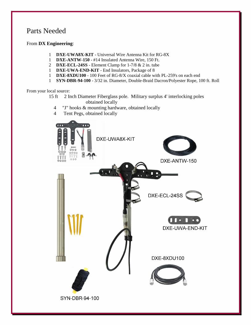
From DX Engineering:
1 DXE-UWA8X-KIT - Universal Wire Antenna Kit for RG-8X
1 DXE-ANTW-150 - #14 Insulated Antenna Wire, 150 Ft.
2 DXE-ECL-24SS - Element Clamp for 1-7/8 & 2 in. tube
1 DXE-UWA-END-KIT - End Insulators, Package of 8
1 DXE-8XDU100 - 100 Feet of RG-8/X coaxial cable with PL-259's on each end
1 SYN-DBR-94-100 - 3/32 in. Diameter, Double-Braid Dacron/Polyester Rope, 100 ft. Roll
From your local source:
15 ft 2 Inch Diameter Fiberglass pole. Military surplus 4' interlocking poles
obtained locally
4 "J" hooks & mounting hardware, obtained locally
4 Tent Pegs, obtained locally

- 6 -
Construction
Using the DXE-ANTW-150 - #14 Insulated Antenna Wire, cut four wires. Two
wires are 25 Ft each (40 meter side) and 2 wires are 38 Ft each (80 meter side). No
further length adjustment will be needed.
Assemble the DXE-UWA8X-KIT - Universal Wire Antenna Kit
for RG-8X per the instructions supplied. The antenna wires are
connected to the Center "T" using the supplied ring terminals.
Connect one 25 Ft. wire and one 38 Ft. wire to each leg of the
Center "T".
Using four DXE-UWA-END-KIT End Insulators, weave the
antenna wire ends as shown in the DXE-UWA8X-KIT instructions.
Using the SYN-DBR-94-100 - 3/32 in. Diameter, Double-Braid
Dacron/Polyester Rope, 100 ft. Roll, cut four ropes. The rope
lengths from the End Insulators to the Tent Pegs are: Two at 7 Ft.
and two at 20 Ft. Allow extra rope length to tie to the End
Insulators and the Tent Pegs. Keeping that in mind, cut the ropes:
Two at 10 Ft. each and two at 23 Ft. each.
The knot shown for Dacron Polyester Rope will not slip and yet is
easily adjustable.
The Center "T" is held in place on the top mast using two DXE-ECL-24SS - Element Clamps as shown in
the pictures shown on pages 7 and 8.
The J-Hooks mounted on the top fiberglass pole (shown on page 8) are optional and are used to wind the
antenna wires on when not in use. You could also just coil the wire up and use small ties to hold the loops
together.
The overall length from the center "T" to each tent peg is 45 feet (diagonal measurement). This sets up each
leg of the NVIS antenna to the proper angles.

- 7 -
When the antenna is set up, run the DXE-8XDU100 RG-8/X coaxial cable to your tuner and connect the
tuner to your transceiver. The tuner is necessary to provide the correct impedance match for proper
operation with your transceiver. You are ready to get on the air using NVIS technology with a portable
antenna that can be packed up and taken just about anywhere!

- 8 -
Element Clamps and J-Hook Details
- 9 -
DX Engineering Parts Used
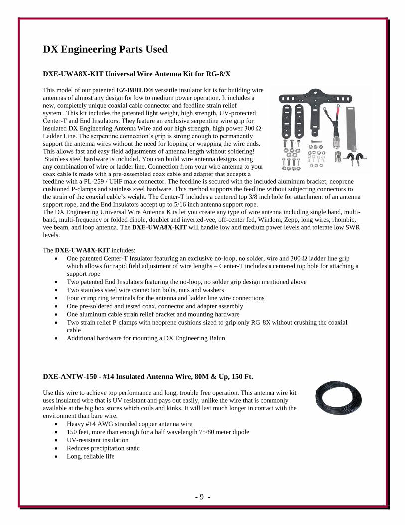
DXE-UWA8X-KIT Universal Wire Antenna Kit for RG-8/X
This model of our patented EZ-BUILD® versatile insulator kit is for building wire
antennas of almost any design for low to medium power operation. It includes a
new, completely unique coaxial cable connector and feedline strain relief
system. This kit includes the patented light weight, high strength, UV-protected
Center-T and End Insulators. They feature an exclusive serpentine wire grip for
insulated DX Engineering Antenna Wire and our high strength, high power 300 Ω
Ladder Line. The serpentine connection’s grip is strong enough to permanently
support the antenna wires without the need for looping or wrapping the wire ends.
This allows fast and easy field adjustments of antenna length without soldering!
Stainless steel hardware is included. You can build wire antenna designs using
any combination of wire or ladder line. Connection from your wire antenna to your
coax cable is made with a pre-assembled coax cable and adapter that accepts a
feedline with a PL-259 / UHF male connector. The feedline is secured with the included aluminum bracket, neoprene
cushioned P-clamps and stainless steel hardware. This method supports the feedline without subjecting connectors to
the strain of the coaxial cable’s weight. The Center-T includes a centered top 3/8 inch hole for attachment of an antenna
support rope, and the End Insulators accept up to 5/16 inch antenna support rope.
The DX Engineering Universal Wire Antenna Kits let you create any type of wire antenna including single band, multi-
band, multi-frequency or folded dipole, doublet and inverted-vee, off-center fed, Windom, Zepp, long wires, rhombic,
vee beam, and loop antenna. The DXE-UWA8X-KIT will handle low and medium power levels and tolerate low SWR
levels.
The DXE-UWA8X-KIT includes:
One patented Center-T Insulator featuring an exclusive no-loop, no solder, wire and 300 Ω ladder line grip
which allows for rapid field adjustment of wire lengths – Center-T includes a centered top hole for attaching a
support rope
Two patented End Insulators featuring the no-loop, no solder grip design mentioned above
Two stainless steel wire connection bolts, nuts and washers
Four crimp ring terminals for the antenna and ladder line wire connections
One pre-soldered and tested coax, connector and adapter assembly
One aluminum cable strain relief bracket and mounting hardware
Two strain relief P-clamps with neoprene cushions sized to grip only RG-8X without crushing the coaxial
cable
Additional hardware for mounting a DX Engineering Balun
DXE-ANTW-150 - #14 Insulated Antenna Wire, 80M & Up, 150 Ft.
Use this wire to achieve top performance and long, trouble free operation. This antenna wire kit
uses insulated wire that is UV resistant and pays out easily, unlike the wire that is commonly
available at the big box stores which coils and kinks. It will last much longer in contact with the
environment than bare wire.
Heavy #14 AWG stranded copper antenna wire
150 feet, more than enough for a half wavelength 75/80 meter dipole
UV-resistant insulation
Reduces precipitation static
Long, reliable life
- 10 -
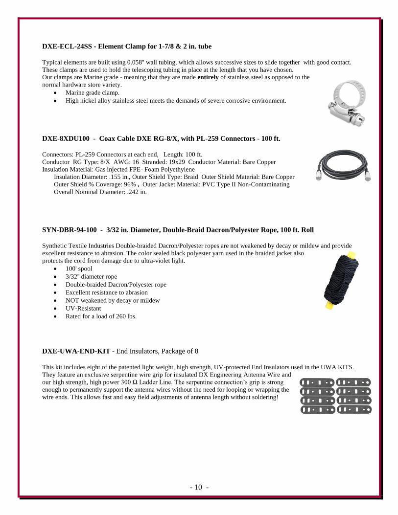
DXE-ECL-24SS - Element Clamp for 1-7/8 & 2 in. tube
Typical elements are built using 0.058'' wall tubing, which allows successive sizes to slide together with good contact.
These clamps are used to hold the telescoping tubing in place at the length that you have chosen.
Our clamps are Marine grade - meaning that they are made entirely of stainless steel as opposed to the
normal hardware store variety.
Marine grade clamp.
High nickel alloy stainless steel meets the demands of severe corrosive environment.
DXE-8XDU100 - Coax Cable DXE RG-8/X, with PL-259 Connectors - 100 ft.
Connectors: PL-259 Connectors at each end, Length: 100 ft.
Conductor RG Type: 8/X AWG: 16 Stranded: 19x29 Conductor Material: Bare Copper
Insulation Material: Gas injected FPE- Foam Polyethylene
Insulation Diameter: .155 in., Outer Shield Type: Braid Outer Shield Material: Bare Copper
Outer Shield % Coverage: 96% , Outer Jacket Material: PVC Type II Non-Contaminating
Overall Nominal Diameter: .242 in.
SYN-DBR-94-100 - 3/32 in. Diameter, Double-Braid Dacron/Polyester Rope, 100 ft. Roll
Synthetic Textile Industries Double-braided Dacron/Polyester ropes are not weakened by decay or mildew and provide
excellent resistance to abrasion. The color sealed black polyester yarn used in the braided jacket also
protects the cord from damage due to ultra-violet light.
100' spool
3/32'' diameter rope
Double-braided Dacron/Polyester rope
Excellent resistance to abrasion
NOT weakened by decay or mildew
UV-Resistant
Rated for a load of 260 lbs.
DXE-UWA-END-KIT - End Insulators, Package of 8
This kit includes eight of the patented light weight, high strength, UV-protected End Insulators used in the UWA KITS.
They feature an exclusive serpentine wire grip for insulated DX Engineering Antenna Wire and
our high strength, high power 300 Ω Ladder Line. The serpentine connection’s grip is strong
enough to permanently support the antenna wires without the need for looping or wrapping the
wire ends. This allows fast and easy field adjustments of antenna length without soldering!

- 11 -
Technical Support
If you have questions about DX Engineering products, contact DX Engineering at (330) 572-3200.
You can also e-mail us at:
Warranty
All products manufactured by DX Engineering are warranted to be free from defects in material and workmanship for a
period of one (1) year from date of shipment. DX Engineering’s sole obligation under these warranties shall be to issue
credit, repair or replace any item or part thereof which is proved to be other than as warranted; no allowance shall be
made for any labor charges of Buyer for replacement of parts, adjustment or repairs, or any other work, unless such
charges are authorized in advance by DX Engineering. If DX Engineering’s products are claimed to be defective in
material or workmanship, DX Engineering shall, upon prompt notice thereof, issue shipping instructions for return to
DX Engineering (transportation-charges prepaid by Buyer). Every such claim for breach of these warranties shall be
deemed to be waived by Buyer unless made in writing. The above warranties shall not extend to any products or parts
thereof which have been subjected to any misuse or neglect, damaged by accident, rendered defective by reason of
improper installation, damaged from severe weather including floods, or abnormal environmental conditions such as
prolonged exposure to corrosives or power surges, or by the performance of repairs or alterations outside of our plant,
and shall not apply to any goods or parts thereof furnished by Buyer or acquired from others at Buyer’s specifications.
In addition, DX Engineering’s warranties do not extend to other equipment and parts manufactured by others except to
the extent of the original manufacturer’s warranty to DX Engineering. The obligations under the foregoing warranties
are limited to the precise terms thereof. These warranties provide exclusive remedies, expressly in lieu of all other
remedies including claims for special or consequential damages. SELLER NEITHER MAKES NOR ASSUMES ANY
OTHER WARRANTY WHATSOEVER, WHETHER EXPRESS, STATUTORY, OR IMPLIED, INCLUDING
WARRANTIES OF MERCHANTABILITY AND FITNESS, AND NO PERSON IS AUTHORIZED TO ASSUME
FOR DX ENGINEERING ANY OBLIGATION OR LIABILITY NOT STRICTLY IN ACCORDANCE WITH THE
FOREGOING.
©DX Engineering 2012
DX Engineering®, DXE®, DX Engineering, Inc.®, Hot Rodz®, Maxi-Core®, DX Engineering THUNDERBOLT™,
DX Engineering Yagi Mechanical®, EZ-BUILD®, TELREX® and Gorilla Grip® Stainless Steel Boom Clamps, are
trademarks of PDS Electronics, Inc. No license to use or reproduce any of these trademarks or other trademarks is given
or implied. All other brands and product names are the trademarks of their respective owners.
Specifications subject to change without notice.