![Damage modeling using higher-order finite element … modeling using higher-order finite element formulation ... plasticity context [5] or in ... the positive definiteness of tangent](https://static.fdocuments.net/doc/165x107/5afd39257f8b9aa34d8d26ac/damage-modeling-using-higher-order-finite-element-modeling-using-higher-order.jpg)
A Plasticity Theory and Finite Element Implementation of ... · A Plasticity Theory and Finite...
12
Jurnal Kejuruteraan 10 (199H) 51-62 A Plasticity Theory and Finite Element Implementation of Friction Model Ahmad Kamal Ariffin Mohd. Ihsan ABSTRACT A .//';(,Tiol1 model /Jased Oil plasticifY Theory is presented. An infc1:t(ICl' element was used in Ihe finile elemclIl implementation . . A.II il1crel11cllwl- ireratit'e sollltion strale:{y was suggested In simulate the nOli-iiI/ear I'rohlel11 hi ii"jerioll. The nIodel !esled to simula!e the friclion ;;nre the (jecr;rHl of" a powder compact compot/em .Ii"Onl {/ die. The numerical simll/arioll r('slflls were l'alidafed alld shows good agreemellf. ..... BSTRAK Saw model gcserlll1 hcrdasllrkan fcori plaslik dihe11langkun . .';;aru III/sur al/lara-lIIllka digullakull da/am implemelllasi III/sur feritillgga. Slrufegi penyelesaian ,okokall-Ielaran dicat!wlgkan hagi mell ... ·e!uku nwsalah fak- /elllruJ da/um geJenJl/. Model ini dhU'i ulllUk penyelakuun daya gl'seran terhaduJl daya folakall komponen padalall serhuk dari dahull (/Cllan. KrpufIlsul1 prnyelakllan herangka felah dihukfikall dall mCI1I1njllkan kel'lItusan )-'a/IX ho;k. INTRODUCTION Friction appears as a consequence of the interaction between two bodies. The nature of friction forces developed during contact and sliding is extremely complex and is affected by a number of factors stich as the characteristics of the interface. the time scale and the frc4uency of the contact. the response of the interface to nonnal forces. inertia and thermal effects. the roughness of the contact surfaces. history of loading. wear and general failure of the interface materials. the presem:e or absence of lubric<.mts and so on (Oden and Martin. 1985) Recently. much attention has been devoted to the numerical analysis of friction and contact in general engineering problems. Despite this. friction modelling is not so well developed as a continuum mechanics modelling. and further work in this area is still needed. In order to take into account the frictional effects, several treatments have been considered in conjunction with finite element modelling. Most of the finite element implementations of frictional phenomena have been based on the classical Coulomb law (Coccoz et aJ. 1994). A Tresea friction law which is a generalisation of the Coulomb frictional law has also been used Uinka 1992), More recently. frictional phenomena have been considered within the framework of the theory of plasticity. Elastoplastic analogies have neen used 10 devise the frictional algorithms (Curnier 1984: Schonauer 1993). Also due to its effect at the microscopic scale. micro-mechanical models have also been used in
Transcript of A Plasticity Theory and Finite Element Implementation of ... · A Plasticity Theory and Finite...

Jurnal Kejuruteraan 10 (199H) 51-62
A Plasticity Theory and Finite Element Implementation of Friction Model
Ahmad Kamal Ariffin Mohd. Ihsan
ABSTRACT
A .//';(,Tiol1 model /Jased Oil plasticifY Theory is presented. An infc1:t(ICl'
element was used in Ihe finile elemclIl implementation . . A.II il1crel11cllwlireratit'e sollltion strale:{y was suggested In simulate the nOli-iiI/ear I'rohlel11 hi ii"jerioll. The nIodel ~I'as !esled to simula!e the friclion ;;nre (~r the (jecr;rHl of" a powder compact compot/em .Ii"Onl {/ die. The numerical simll/arioll r('slflls were l'alidafed alld shows good agreemellf.
..... BSTRAK
Saw model gcserlll1 hcrdasllrkan fcori plaslik dihe11langkun . .';;aru III/sur
al/lara-lIIllka digullakull da/am implemelllasi III/sur feritillgga. Slrufegi
penyelesaian ,okokall-Ielaran dicat!wlgkan hagi mell ... ·e!uku nwsalah fak/elllruJ da/um geJenJl/. Model ini dhU'i ulllUk penyelakuun daya gl'seran terhaduJl daya folakall komponen padalall serhuk dari dahull (/Cllan.
KrpufIlsul1 prnyelakllan herangka felah dihukfikall dall mCI1I1njllkan kel'lItusan )-'a/IX ho;k.
INTRODUCTION
Friction appears as a consequence of the interaction between two bodies. The nature of friction forces developed during contact and sliding is extremely complex and is affected by a number of factors stich as the characteristics of the interface. the time scale and the frc4uency of the contact. the response of the interface to nonnal forces. inertia and thermal effects. the roughness of the contact surfaces. history of loading. wear and general failure of the interface materials. the presem:e or absence of lubric<.mts and so on (Oden and Martin. 1985)
Recently. much attention has been devoted to the numerical analysis of friction and contact in general engineering problems. Despite this. friction modelling is not so well developed as a continuum mechanics modelling. and further work in this area is still needed. In order to take into account the frictional effects, several treatments have been considered in conjunction with finite element modelling. Most of the finite element implementations of frictional phenomena have been based on the classical Coulomb law (Coccoz et aJ. 1994). A Tresea friction law which is a generalisation of the Coulomb frictional law has also been used Uinka 1992), More recently. frictional phenomena have been considered within the framework of the theory of plasticity. Elastoplastic analogies have neen used 10 devise the frictional algorithms (Curnier 1984: Schonauer 1993). Also due to its effect at the microscopic scale. micro-mechanical models have also been used in

52
the treatment of friction and their results incorporated into a constitutive theory (Rodic and Owen 1989).
Another issue in this modelling is the treatment of the interface. The interface behaviour has been modelled by a connecting node between the workpiece and die (Park 1985). This has been extensively used in the metal forming processes especially in sheet metal simulation. In this type of treatment. common connected nodes were used for different materials which may not represent the real situation when a thin layer of oxide or lubricant lies in between them. Another approach for representing this interface behaviour is to use a contact layer which has a very small thickness (Vakhroucher et al. 1992). In this case. another type of domain was considered as an interface material. A more robust treatment is associated with using an interface element (Rodic and Owen 1989) with one side representing the die and the other representing the workpiece. The work presented in this paper will address the macromechaoical model of the friction incorporating the plasticity anology and the used of an interface element in the finite element procedure.
PLASTICITY THEORY OF FRICTION
One of the first descriptions of frictional behaviour which can be derived from the classical theory of plasticity can be found in Fredriksson (1976). The formulation can be achieved from an analogy between frictional and plastic phenomena. Table I presents the related formulation to a plasticity model. The fonnulation of frictional phenomena are discussed as itemised below.
TABLE I. Plasticity and fricion theory
Plasticity
elastic elastic-plastic yield criterion
hardening/softening rules flow rules
STICK REGION
Friction
stick stick-slip
friction criterion tearing/wearing rules
slip rules
The physical meaning of the stick region is that sticking is caused by the elastic defonnation of the asperities at the contact surface. The sticking behaviour in the tangential direction is described by
(I)
The tangent stress, ,leads to a tangential shear displacement, g;' with coefficient of sticking, c,' In a closed or rigid die, it is assumed for simplicity that there is no movement in the normal direction because there will be no penetration of workpiece into the tools. so the normal displacement. g;;:;:::: o. Figure I shows a clear view of the shear force and displacement in a quasistatic compaction or more obviously during ejection of the component from the die.

53
hardenin!-":
r
---:""------------- srick+pniec'lly-slip ..
• • so.ffenillg
~I---,,--g, g,
FIGURE 1. Shear stress - shear strain
STICK·SLlP DECOMPOSITION
The shear displacement is decomposed into two parts; stick and slip. which is in principle the same as the decomposition of elastic and plastic behaviour. The stick is reversible and the slip is irreversible. As mentioned earlier. the nonnal displacement is assumed to be zero so only a tangential displacement will be considered which consists of stick and slip decompositions.
- <' - I' g, -!?, - gr (2)
where g;' and 8:' are the tangential shear displacement for stick and slip
respectively.
FRICTION CRITERION
A friction criterion is the indicator whether tangential sticking or slipping occurs. If the friction force reaches a certain threshold, called the slip limit, then relative shearing occurs. The general fonn is given as
F(~.cr.){<O stick (:l) J '= 0 slIp -
The most common friction criterion for a perfect friction state is the Coulomb law which can be expressed mathematical1y as
where r is frictional shear stress, aN is nonnal stress, )1 is friction coefficient and c,. is friction cohesion. The nonnal stress should in under compression condition or there will be no friction between the workpiece and the die if the stress is under tensile condition. Or more generally as suggested by Curnier (1984) which includes wear and tear model,
(5)
where exponent a and constant b denotes the tear and wear phenomena.

WEAR AND TEAR
The \'vl.!'m and Ie-af is the phl'nol11cna of hi.lnkning ami softening during
"Iiding: . If IhlS pht'llomenon is ignored. the friclional heh:lviour is ant\logous In a pe rf~l'll y plas tic material in plast ic ity. The Idnemalit: variables of ~ (ick and :-. lip art" i.lssodalcd \\:ilh tilt' fril'tion rorce und also wear and lLar force s. Th,,"sc two forces \Ve re introduced as different fomls of the same phenomenon (i.e. grinding-in) (Curnier. 19X.:l: Rodic and Owen. Il)X9) and both processes wl:J'e ass Llmed to produce a reduction in the force of frk'tion. The shear "tress inl.:J'~as(':-. when the hardening mechanism s occur and conve rsely. ""hen the
shear slress decreases. the softening mechani sm rake ... place. The tkvdopment of shear fort'e during shearing b dependent 011 the
leng th of the compacted part which has heen found in several references (Ernst a nd Barnekow, 1994-). wh ic h des(.'ribe typical examples for this bt'haviour. III ejection. the sheaf force dC'cn:~lst's I' Of th e: shorter component. On the olhc:-r hand, the shear fon.:e in cre~l:-.es for longer component.
SLIP Kl l LES
The direction of slip. is governed by s lip rules deriving from a slip
pOIenlial. Z
I " iI/ ., J " ilL £ ,, ' = 11"'1 -- Ullu ,, ' - m
,-., 't'dt ,-. " - 't" VT \ (6)
where cp is a constant expressing the colinearity of the slip increment with
the uutward normal to the slip potential. If Z is replaced by the slip criterion F . the slip rule becomes associated. Physil.:'ully. this is not acceptable , hec<lu"e it w ill create a gap (separation) ~IS shearing process proceeds. The non-associated slip rule is therefore more app licable 10 model the friction probkm, r igurc:::! shows a better viev.' of the associated and non-assoL'iatcd ..; li p rule applied [0 contact behaviour. It l..:learl y shov .. "s thai the direction of
r
F
7.
. a"
FIGURE 2. Slip su rf.Kc c riterion and flOIl-a\\o(,:ialcd ... Iip rules

slipping is parallel to the direction of shearing stress. The non-associated slip rule. by analogy. is the same as associated flow rule in the von Mises criterion in plasticity.
COMPUTATION OF THE FRICTIONAL PROBLEM
A special six-Iloded isoparametric interface element was used in the finite element discretization procedure and this is shown in Figure 3. The first three nodes of this element represent the workpiece material on one side and the tool on the other side. After giving the definition of displacement and strain by using: the standard finite element. the stress-strain relationships for this interface element have to be defined which represent the normal and shear relationships. The normal is to capture the asperity deformation in the workpiece material or the tooling. whereas the shear relationship is dependent on the yield criterion. The frictional stiffness matrix was then calculated from these relationships to give the stress-strain matrix at a particular element.
Y'I' ,
,
1
ry
t • • -I (J (,
\ or I
(a) glohal defination (h) local defination
FIGURE 3. Global and local definations of interface element
FINITE ELEMENT APPROXIMATIONS
By using shape functions as the usual way in the finite element procedure. the displacement at any point; on the powder side is given by the vector {II 1 and on the tooling by I II I.
r ' For the special element shown in Figure 3. the displacement of node i in the local ; and I} axes needs to be defined. The shape functions N associated with node i are expressed in terms of the local ~ coordinate as'
N, <~(~-I) i; 1.6 (7)
N, ;1-;;' i = 1.5 (8)
N, < E,(E, + I) i; 3.4 (9)

56
The unit tangent and vector nonnal to the interface are respectively given by
I[ax ~] n=J o~'+ o;J (10)
and I[~. ax] s=J 0;'+ o;J ( II )
where the Jacobian J is related to the length L of the interface
( 12)
The transformation from global to local displacement (or strain) is then given by the following matrix and is introduced to deal with the arbitrarily orientated surface geometry of the tooling i.e.
T=[; ] ( 13)
Therefore, the local displacement is obtained from the following transformation
(14)
(15)
The local relative displacements are defined as the difference between the local displacement of the workpiece and the tool. i.e
(16)
From equations (14) and (15). then (16) leads to the relationship
where B,=TN (17)
Since the interface is a zero thickness element. the definition of strain is taken directly from the relative displacement in equation (16).
CONSTITUTIVE RELATIONSHIP
The normal strain is considered negligible and is governed mainly by asperity deformation at the contact. Since the nonnal stress is significant. the small strain is achieved by prescribing a large modulus coefficient Er. Also this is chosen since deformation in this nonnal direction does not . have any significance in the forming process (Burr and Donachie 1963). Thus. 'he nonnal stress-strain relationship can be achieved by means of a linear equalion
( 18)

57
where E, can be chosen to capture asperity contact as an appropriately chosen large number. In this work, the value used is 105. Equation (I) expressed the tangent stress which has been decomposed into stick and slip part. Considering the stick region first, the incremental form of the shear stress-strain relationship can be given as
(19)
where the sticking coefficient is proportional to the stick shear modulus of the workpiece and tool as shown in Figure I. The shear force then. is limited by the slip criterion as in equation (4) or (5). However. because of the availability of experimental data (Gethin et aI, 1994), the shear stress-strain relationship for the stick-slip region can be obtained.
The stiffness matrix at the interface is defined using the standard finite element method, i.e
K~ fB;DfBfdL L.
(20)
where Le is the length of the interface element. Df
is the stress-strain matrix in the local coordinate system. So that the stress-strain can be written in incremental form as
(21)
(22)
The frictional non-linearity is produced by the modulus of slip shear which can be obtained in tenns of the gradient of relationship between shear stress and shear strain.
The non-linearity of the friction problem needs the application of numerical techniques. The incremental-iterative solution strategy is used. incorporating the frictional parameters. The total computational procedure is summarised in Appendix I.
NUMERICAL EVALUATION AND VALIDATION
In the literature review, friction is well known as an important parameter where it may affect the applied forces, stresses and density variation throughout the component. Figure 4 illustrates the variation of experimental ejection force as a compact component drawn out from the die. There are two regions which may be defined as stick friction and follows by slip friction. The curves also show clearly that the level of ejection force is very dependent on the length. Details of this phenomena has been explained (Gethin et al. 1994) where the ejection stage is considered. These information data is used in this work for numerical input data and the experimental validation.
The incremental form of the shear stress-strain relationship under this stick region can be given by;
(23)

58
" .,,-----------20mm fill deptb 40mm Ull depth
I • :5 .. I~---
i· J ID , , r ~. M. !:
.4 •• MI~I ......... ~"IO.SIII.4D
Bol\om puDch ~l, mill aouc. puhGb. &.pl_l mm
.,,------------80mm fill depth
Q ~ • » ~ 10 10 ~ 10 Bottom pua.ch cU.pla __ t. mID
FIGURE 4. Ejection force for iron powder
where G I is the stick shear modulus which is given by the slope in this region. In the slip region. the slip shear modulus. G, is appropriate. This slip modulus is given by the slope in the slip region. The values of stick and slip modulus summarised in Table 2 are used in this work.
TABLE 1. Stick and slip modulus
G,(N/mm'l 20 mm 40 mm
150 ·2.10 0.05
Figure 5 shows the effect of friction modulus associated with the stick and slip behaviour during ejection phase. Figure 5(a) shows the variation in ejection force over a range of stick modulus (l1O . 180 N/mm2). It is evident that when a higher stick modulus is applied. the ejection force to break the static friction is higher. Figure 5(b) shows the effect of slip modulus changes (·2.0· 2.0 N/mm'l and clearly the modulus has a significant effect on the level of the ejection force.
Figure 6 shows the simulation of the ejection force which is compared with the experimenal results for 20 mm and 40 mm length component. Good agreement has been achieved when using the friction modulus imput data in Table 2 which incorporates the softening function established from experimental work. In comparing the numerical stability during ejection. the Newton- Cotes integration was found to be more stable than Gauss integration. This is attributed ot the higher order error for Gauss integration for the same number of integration point used.

59
10
z 6 /-~
'1i 2 ," = 4 .2
/ 0 0 U]
110 N/mm'
2 ./ 150 l\/mmc
IHO N/mnr'
o ~ ____ ~ ______ ~ ____ ~ ______ ~ ____ ~ ______ ~
o ) 4 6
Bollom punch displacement. mm
FIGURE 5(a). Variation of ejection force for different stick friction modulus
Z ~
~
~ '" = .g 0
"-'"
10 -r---------------------....,
6 -
4 -
2 -
-------- -2.0 N/mmc
-D.ON/mm'
1.0 N/mmc
o -+----r----r-,---r-,---r-,---r-,---T-,---T-I---T-,---T-,--~ o 2: J 4 S 67 g 9 10
Buttum punch displacement. mill
FIGURE 5(h). Variation of eje("tion force for different slip friction modulus

60
Z .0<
oi e
'" c .~ ti ~
iii'
20mm fill depth
10,-----------------------------~
8
6
4
2
o 2 4 6 8
-- exp ... ----. Newton..cotes --6- Oauss
10 12 14 16 18 20
Bottom punch displacement. mm
40mm fill depth 20.-----------________________ ~
-- exp 15 ......... fem ,
i ; i 10 I J
5 f
o 5 10 15 20 25 30 35 40 Bottom punch displacement. mm
FIGURE 6. Experiment and numerical results on ejection
CONCLUSION
A friction model is completed based on a plasticity theory. Basic ingredient of the model consist of stick-slip decomposition. friction criterion. wear and tear rules and slip rules. In implementing the theory. the numerical procedure incorporating finite element was used. Good agreement has been achieved between simulation and experimental observation.
a, h ('
1 C
" (' , D E F
f gil g, U,V
Z rp !l C1
tj x,yor:.r
NOTATION
Wear and tear constant Cohesion of friction
Coefficient of slipping
Coefficiem of slicking
Ela"ticity matrix Young modulus
Friction funcl ion
Stick/slip nonnal displacement
Stick/slip langen displacement
Displacement tensor Slip function
Plastic multiplier
Friction coefficeint
Stress tensor Friction shear stress
Plane or axisymmetric coordinate system for global
defination
61
( and 11 Local defination coordinate system
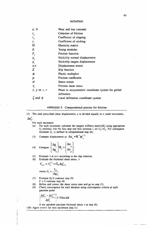
APPENDIX I: Computational process for friction
(I) The tOlal prescribed shear displacement, « is divided equally to n small increments,
Au;. For each increment (a) For each increment. calculate the tangent stiffness malrix[KJ using appropriale
Gr modulus. For the first step and first iteration i. set Gf=G •. For subsequent iterations G, is defined in computational step (6).
(3)
(4)
(5)
(61
Compute displacemeOi as flu =K ·1"i-1 , "
Compule {tlg' }B ={tlUp} . tlg f tlv
" , Evaluate t at n+ 1 according to the slip criterion. Evaluate .he frictional shear stress. r
I i -I G A i t,,+l == 'til + F~gll + 1
tE who ... G, = -I - I tlg,
(7) Evaluate fs. 0 continue step (9)
F > a continue step (8)
(8) Refine and correct the shear stress state and go to step (5). (9) Check convergence for each iteration using convergence criteria at each
gaussian point
' " ~ TOLLER ',tlt ' - tlt,-I I
.1< if not satisfied calculate frictional stress t at step (6).
(10) Again n=n+ 1 for next increment step (I)

62
REFERENCES
Burr, M F. & Donachie JR, M. J. \96 .; , Effect of Pressing Oil Copper Powder.." Trails . ASM 56: ~63-g66.
C()(.'C()Z. G .. Belle!. M .. Lec:ot. R. Ackermann. L. & Hagghl:.ld. H. A. 1l)l)4. Powder Ml'tallurgy l't'fWh/ COlIgrc.fJ. 7()t)-712.
Curnier. A. 1984. A Theory of Fridion. /111 . .I. Solids S'r//('fllres 2017 1: 6.n -M 7. Ernst. E. & BarncJ:.ow. D. 1994. Pressure. Friction .md Densit y During Axial Puwder
Compaction . PO\.l'd('l" Mt'Tallllrgy World COllgress I: 673-676. Fredriksson. B. 1976. Finite Element Solution of Surface Non-linearities in Structural
Mechunks with Sphecial Emphas i:oo to Contact and Fracture M('('hanics Prohlcms. Comp. & Structures 6: 2MI-190.
GClhin. D. T .. Ariffin. A. K., Trail . V. D. & Lewi:".. R. W. 1<;.l9 .. L Compaction and Ejection of Green Powder Compact. POIl'dC'1" Mcrallllrgy 37: -'] · 52.
Jinku. A . G. K . 1992. Finite EI~mcnl Silllul<llion of Powd~r. ClllUpa~ lion Fonuing Pro(.'~!!O~es. PhD. Thesis. UWS Civil Eng C/Ph/155!9.2.
Oden. J. T. & Martins. 1. A. C. JI}H~ . Models & Comput;.uional MClhods I'm Dynamic Friction Phenomena. COIIII'II1. Merhs. ApI'/. Me(·IJ. EI/g. 51: )17·t)1~.
Park. J. K. 1985. Die Compaction or Powder. Constiluti\"e Modelling & Finite Element Calculations. PhD The~is Univ. North Carolina.
Rodic. T. & Owen. D. R. J. 1989. A Plasticity Theory uf Friction and Joint Elements. Pmc. 2/1d. COMPLAS CO/{. I04~·1062. Barcelona.
Schonauer. M. 1993. Unified Numerical Analysis of Cold and Hot Metal Forming Processes. PhD Thes is. UWS PhI l 72/93.
Vakhrom.:hev. A. V. & Vakhrouchev.1. l. l. J99~. The Finile Elam;:Ull Amllysis of Ihe Powder Material Compression. In Numerical Methods in Ind . Fonning Processe~ .
Chenot. Wood & Zienkiewicz (cds.). RotLerdam: Balkema.
Department of Mechanical and Materi als Engineering Faculty or Engineering Universiti Kebangsaan Malaysia 43600 UKM B"ngi Selan,gor D.E. Malaysia