A Parametric Modelling Process for the Integration of ...
10
Proceedings of the IASS Annual Symposium 2016 “Spatial Structures in the 21st Century” 26–30 September, 2016, Tokyo, Japan K. Kawaguchi, M. Ohsaki, T. Takeuchi (eds.) Copyright © 2016 by W. Pan, Y. Sun, M. Turrin, S. Sariyildiz, J. Paul Published by the International Association for Shell and Spatial Structures (IASS) with permission. A Parametric Modelling Process for the Integration of Architecture and Structure in Large Multi-functional Sports Hall Design: a Case Study Wang PAN*, Yimin SUN a , Michela TURRIN b , Sevil SARIYILDIZ b , Joop PAUL b *State Key Lab of Subtropical Building Science, South China University of Technology, China; *Faculty of Architecture and the Built Environment, Delft University of Technology, The Netherlands; Julianalaan 134, 2628BL, Delft, the Netherlands [email protected] a State Key Lab of Subtropical Building Science, South China University of Technology, China b Faculty of Architecture and the Built Environment, Delft University of Technology, The Netherlands Abstract The integration of architectural (functional spaces) and structural design is especially crucial for the conceptual design of large multi-functional sports halls, due to the strict regulations for functional spaces, the requirement of large-span structure, and the complex interrelationships between these two aspects. This on-going research aims at developing a computational method to support this integration during the conceptual design of large sports hall. This paper proposes a parametric modelling process to support a design exploration which is an important part of the computational method. A typical and simplified large multi-functional sports hall is used as an example case to demonstrate this process. Keywords: parametric modelling process, large multi-functional sports hall, functional space, large-span structure, design exploration. 1. Introduction 1.1 Large multi-functional sports hall A sports hall is an enclosed space that contains a designed indoor sport field or a permutation of indoor sports fields (P. Culley, J. Pascoe. [3]), which is covered by a large roof with large-span structure (conventionally, the span is larger than 20m). According to international practice, a large multi-functional sports hall (arena type), should accommodate at least an international gymnastics competition (60m×34m×12m) and other non-sports events, and provide at least 6,000 spectator seats. 1.2 Integration of architectural functional requirements and structural requirements (of large- span structure) Functional spaces, which are used to cater to specific functions of the building, are concerned with quantitative requirements in architectural design. The main functional space in a sport hall is playing hall (or competition hall), which can be divided into a Critical Overall Space (COS) for various sports and non-sports activities (Sports England. [13] [14]) and a Spectator Viewing Area (SVA) for spectator accommodation (BE EN 13200-1: 2012. [15]). For a large multi-functional sports hall, the COS, as mentioned above, should accommodate a standard gymnastics field; and considering the daily use, badminton court is conventionally used as a module for the dimension of COS (Sports England, 2012 [13]). Furthermore, according to the multi-functionality, the dimension of COS also needs to cater to non-sports activities (concerts, dramas, exhibitions).
Transcript of A Parametric Modelling Process for the Integration of ...

Proceedings of the IASS Annual Symposium 2016 “Spatial Structures in the 21st Century” 26–30 September, 2016, Tokyo, Japan
K. Kawaguchi, M. Ohsaki, T. Takeuchi (eds.)
Copyright © 2016 by W. Pan, Y. Sun, M. Turrin, S. Sariyildiz, J. Paul Published by the International Association for Shell and Spatial Structures (IASS) with permission.
A Parametric Modelling Process for the Integration of Architecture and Structure in Large Multi-functional Sports Hall
Design: a Case Study Wang PAN*, Yimin SUNa, Michela TURRINb, Sevil SARIYILDIZb, Joop PAULb
*State Key Lab of Subtropical Building Science, South China University of Technology, China; *Faculty of Architecture and the Built Environment, Delft University of Technology, The Netherlands;
Julianalaan 134, 2628BL, Delft, the Netherlands [email protected]
a State Key Lab of Subtropical Building Science, South China University of Technology, China
b Faculty of Architecture and the Built Environment, Delft University of Technology, The Netherlands
Abstract The integration of architectural (functional spaces) and structural design is especially crucial for the conceptual design of large multi-functional sports halls, due to the strict regulations for functional spaces, the requirement of large-span structure, and the complex interrelationships between these two aspects. This on-going research aims at developing a computational method to support this integration during the conceptual design of large sports hall. This paper proposes a parametric modelling process to support a design exploration which is an important part of the computational method. A typical and simplified large multi-functional sports hall is used as an example case to demonstrate this process.
Keywords: parametric modelling process, large multi-functional sports hall, functional space, large-span structure, design exploration.
1. Introduction
1.1 Large multi-functional sports hall A sports hall is an enclosed space that contains a designed indoor sport field or a permutation of indoor sports fields (P. Culley, J. Pascoe. [3]), which is covered by a large roof with large-span structure (conventionally, the span is larger than 20m). According to international practice, a large multi-functional sports hall (arena type), should accommodate at least an international gymnastics competition (60m×34m×12m) and other non-sports events, and provide at least 6,000 spectator seats.
1.2 Integration of architectural functional requirements and structural requirements (of large-span structure) Functional spaces, which are used to cater to specific functions of the building, are concerned with quantitative requirements in architectural design. The main functional space in a sport hall is playing hall (or competition hall), which can be divided into a Critical Overall Space (COS) for various sports and non-sports activities (Sports England. [13] [14]) and a Spectator Viewing Area (SVA) for spectator accommodation (BE EN 13200-1: 2012. [15]). For a large multi-functional sports hall, the COS, as mentioned above, should accommodate a standard gymnastics field; and considering the daily use, badminton court is conventionally used as a module for the dimension of COS (Sports England, 2012 [13]). Furthermore, according to the multi-functionality, the dimension of COS also needs to cater to non-sports activities (concerts, dramas, exhibitions).

Proceedings of the IASS Annual Symposium 2016 Spatial Structures in the 21st Century
2
In addition, the dimension of SVA is related to the accommodation and the views of spectators, which is based on a series of rigorous calculations and limitations (BS EN 13200-1: 2012 [15]). Considering the performing events, the spectators’ seats usually concentrate on the opposite of the stage, which produces an asymmetric SVA (that contradicts with the SVA outlay for sports events).
Furthermore, since the playing hall is a wide column-free space, a large-span structure is required. The overall design requirement for a large-span structure, during the conceptual design, is reducing the self-weight (to save material and construction cost), while enhancing the stiffness (or reducing the elastic strain energy). Meanwhile, different structural typologies with different configurations and topologies, which would influence the overall geometry of the building, should be considered as well.
For the conceptual design of the large multifunctional sports hall, the aspects of the functional spaces (the COS and the SVA) and the large-span structure are crucial, since some vital issues of these aspects and the overall form of the building are mutually determined by each other. The necessity of the integration of these aspects lies in the complex interrelationships among them. The shapes and outlays of the functional spaces, which need to meet the spatial requirements, are interrelated to the shape, the span and the supports of the large-span structure which need to meet the structural requirements. Among these aspects, the overall shape of the sports hall is the interface.
Even through there are various approaches which support the integration of architecture and structure in different ways, rare precedent focuses on the specific interrelationships between functional spaces and large-span structure in sports hall; and in design practices, the design works of these aspects are still separated due to the limitations between the architectural and structural disciplines. In order to overcome these limitations and support the integration of these aspects, a method which can effectively and efficiently process the complex interrelationships is necessary.
1.3 Computational method Computational methods, which have widely used in engineering disciplines, shown their potential in architectural design in recent decades. Computation, in general, is a series of calculations that are integrated with a defined model, which not only calculate numbers, but also process complex information. In the process of computational design, architecture is expected to be integrated with various information; thereby, allow designers to explore the complexity and specificity of architecture, and to tackle the complex interrelationships among various aspects of the building.
Generally, a computational method is an overall framework, which can be achieved by diverse workflows and various combinations of technologies. Based on the literature review performed so far, as well as on previous experiences and preliminary case studies, some specific techniques and tools have been identified for this research. They are parametric modelling, building performance simulation tools (BPSTs), and mathematical optimization technique. The first two have been widely accepted by architects and structural engineers in design works. The optimization, which have been widely used in structural engineering (structural optimization), is studied and implemented in architectural design in recent years.
• Parametric modelling, can generate various alternatives, according to different values of design parameters. During the modelling, design parameters are arranged according to certain structures and hierarchies which are formulated according to the design regulations and principles.
• Building performance simulation tools (BPSTs), in this research, refer to the computer softwares that simulate real working conditions for the models of alternatives to calculate relevant performance data by a series of computations.
• Optimization, in general, is a process within which some optimal solutions are searched (according to the objectives and the constraints) from a set of feasible alternatives. According to the amount of the objectives, there are single-objective optimization (SOO) and multi-objective

Proceedings of the IASS Annual Symposium 2016 Spatial Structures in the 21st Century
3
optimization (MOO); when the optimization problem involving various disciplines, there is multidisciplinary optimization (MDO).
1.4 Research aim of the overall research According to previous analyses, this ongoing research aims at developing a computational design method, for the conceptual design of large multi-functional sports halls, to integrate functional requirements (of the multi-functional hall) and structural requirements (of the large-span structure enclosing the hall).
Within the computational method, a design exploration, which helps designers to understand the complex interrelationships in sports halls and to formulate design problems, is necessary. This paper proposes a parametric modelling process to support this design exploration.
In the following section, some related precedents of the ongoing research are analysed. Then section three focuses on the parametric modelling based design exploration, which is the core of this paper. According to the analyses about the concept and the requirements of the design exploration, the process of the parametric modelling is proposed and demonstrated by a case. The results of the design exploration are discussed in section four, and a conclusion and future works are presented at the end.
2. Related precedents
For various types of buildings, some previous research aimed at improving the integration of architectural qualitative performances and structural performances by an interactive framework (J. Felkner, et al. [2]) or an interactive optimization (C. Muller, et al. [12]). Other precedents focused on providing a close and efficient connection between architectural design and structural design, for structural engineers, by proposing a geometric modelling framework (Podrigo Mora, et al. [11]) or a transformation between architectural spatial models and structural mechanical analysis models (H. Hofmeyer, et al. [7]; J. Delgado, et al. [4]). Despite these two types of research have contributed to the integration of architectural and structural design, some important architectural quantitative performances (such as spatial requirements for certain functions) are still out of consideration, and the connection between architectural spatial model and structural analysis model is mainly for structural engineers.
Some precedents have shown the effects of the computational design that applied in the conceptual designs of large roofs or sports buildings. A parametric modelling method, which is based on shape grammars and is used to generate the spectator viewing area of stadiums, has been developed and used in a real case (Y. Sun, et al. [16]). A simulation tool which simulates human viewing experience has been developed and used in real design (R. Hudson, et al. [8]). A parametric design approach, which integrates relevant engineering disciplines into the architectural conceptual design, has been developed specifically for large roof with the focus on passive climate comfort (M. Turrin. [17]). A Multi-objective multidisciplinary design optimization method for sports buildings envelopes focusing on day-lighting and energy has been applied in case studies (D. Yang, et al. [19] [20]). An integration of spectator bowl and roof structure of a stadium was achieved in the National Stadium of Singapore which has the largest dome in the world and is designed by Arup Group Limited (C. Lewis, et al. [10]). An integrated optimizing design of module spectator grand and its structure is developed based on ANSYS® by D. van Laar in 2015. Among these precedents, some research has integrated structural performance into the architectural conceptual design of large roofs and sports buildings. But considering the specific spatial requirements of sports halls, and various structural types for the large roof, there is still lots of essential work can be done for the integration of architectural and structural design.

Proceedings of the IASS Annual Symposium 2016 Spatial Structures in the 21st Century
4
3. Parametric modelling based design exploration: a case study
In this section, the requirements of the design exploration are analysed, and an example case is used to explain the proposed parametric modelling process and the relevant technologies.
3.1 Requirements of design exploration Generally, design exploration is a process, for designers, that evolves and investigates design space to support design discoveries and decision making. (Mechanical engineering, Brigham Young University, 2014). Specifically for this paper, design exploration enables designers to investigate and analyse the multidisciplinary alternatives (of functional spaces and structures) in a design space, according to various performance requirements.
The aim of the design exploration, in this research, is to enable designers to discover the laws of the interrelationships between design parameters and the performances (of functional spaces and large-span structure), and among the various requirements of these performances. To achieve these, the design exploration requires: • Various integrated alternatives of functional spaces and structures, • Performance data of the alternatives, • Search of the optimal alternatives, according to diverse performance requirements.
3.2 Preliminary process of the parametric modelling
To meet these requirements, a parametric modelling process that integrates with BPSTs and optimization techniques are proposed in this paper. We use a typical large multi-functional sports hall as an example case to explain each component of the process. The requirements of the sports hall for this case are shown as follows: the largest sports field for the COS is a gymnastic field (60m×34m), the principle game is basketball (28m×15m), the number of the fixed spectator seats is 6,000. In order to briefly introduce the approach, we only consider the grid-shell structure with one grid pattern in this case, and ignore the requirements of the SVA for performing events (i.e. concerts, dramas). The basic information about the case is shown in table 1.
Table 1: The basic data for the parametric modelling and the optimization
Variables Objectives of the performances Constraints
COS
R1: the number of the rows of the badminton pitches - The amount of the
badminton pitches Max. The outline of all the pitches should as close as possible to the outline of the largest filed (gymnastic field)
-
C1: the number of the columns of the badminton pitches -
R2: the number of the rows of the exhibition booths - The amount of the
exhibition booths Max. C2: the number of the columns of the exhibition booths -
SVA
h1: the position of the 1st row of the stall (lower tier seats) 3m to 6m The average viewing
distance Min.
Depression angle of the sight-line <40
n1: the number of the rows of the stall 5 to 10 O: Overhanging or not 0 or 1 n: the number of the rows for the stand (higher tier sears) overhanging above the stall
0 to 3 The maximum viewing distance Min
d2: the position of the 1st row of the stand 0 to 3m
Struc-ture
UV: the UV number of the grid-shell pattern U: 10 to 30 V: 10 to 30 The structural mass Min.
dia: the diameter of the cross-section of the elements 0.5m to 1.5m The elastic (strain)
energy Min.
th: the thickness of the cross-section of the elements
0.03m to 0.1m
The maximum bending-energy of each element Min.

Proceedings of the IASS Annual Symposium 2016 Spatial Structures in the 21st Century
5
3.2.1 Parametric modelling Relevant design principles about the case are surveyed and parameterized in a programme, and design parameters are arranged in a structure in this program. Rhinoceros® (a NURBS-based 3D modelling software) with its plugin Grasshopper® (a visual programming tool), is used to support the parameterization.
According to the analyses in section one, we divided the parametric model into three parts: the COS, the SVA, and the large-span structure.
For the COS, considering the multi-functionality, at least three kinds of dimensions are considered. The first one is the largest field (e.g. Gymnastic field in this case), which is usually decided by developers. Then, considering the badminton pitch which is conventionally used as a module, we need to put as many badminton pitches as possible in the COS; and the limitation is that the outline of all the pitches should be as close as possible to the outline of the gymnastic field. The same requirement is also suitable for the arrangements of exhibition booths; the difference is that a 3 meter wide aisle is necessary between the rows of the booths. Finally, the outlines of the three fields are compared, then the maximum width and the maximum length are selected as the final size of the COS. The dimensions of the spaces are shown in figure 1.
Figure 1: The dimension of the COS
The design of the SVA includes a sight-lines design and a traffic design. For the sight-lines, firstly, focus points should be set on the boundary of the field for the principal game (e.g. Basketball for this case). Then a sight-line is a line that connects the nearest focus point and the eyes of a spectator. In order to ensure the sight-lines would not be disturbed by the spectators in the front rows, each row of seats should be raised by a certain height (so called riser height, which need to be calculated for each row by a formula). For the traffic of the spectators, the number of the seats between gangways should not be more than 28, and the number of the rows between two lateral gangways should not be more than 20. Furthermore, the parameters, which are respectively related to the position of the first row of the stall (the lower tier seats), the position of the first row of the stand (the higher tier seats), the numbers of the rows of the stall and of the stand are crucial for the sight-lines design and the outlay of the SVA. The parameters and the criteria are illustrated in figure 2.
For the conceptual design of large-span structure in this case, the overall process is to tackle the parameters (of geometry, support condition, cross-section, material) for grid-shell structure in order to reduce the mass and the elastic strain energy of the overall structure and the internal strain energy of

Proceedings of the IASS Annual Symposium 2016 Spatial Structures in the 21st Century
6
each element. Among the parameters, the geometry is interrelated to the boundary of functional spaces (which is one of the key points of the integration); and the cross-section, in this case, we only consider a round section with different diameters and thickness; the structural material, we only consider steel S275.
Figure 2: The parameters and the criteria of the SVA
(The left part is cited from the “Guide to Safety at Sports Grounds”)
The interrelationships between the aspects of functional spaces and large-span structure are emphasized, since the importances mentioned above. The interrelationships lie in the outlines and the boundaries of each aspect. The COS is interrelated with the SVA through the outline (which is also the inner boundary of the SVA), and the SVA is interrelated with the roof structure through the outline (along which the supports of the large-span structure are arranged). And the structure is also interrelated with both the COS and the SVA through their upper boundaries. Such relations are shown in the following picture.
Figure 3: The integration of the COS, the SVA, and the large-span structure (upper), and the parameterized
interrelationships in Grasshopper (lower)
n: the number of the rows of the stand overhanging above the stall;
1sttype
Focus point
h1= the height of the first row of the stall; n1= the number of the seating rows in the stall (the low tier seats); n= the number of the rows for the stand (the high tier seats) overhanging above the stall; d2=thehorizontaldistancebetweenthestallandthestand; h2= the height of the first row of the stand.
2ndtype
C= the “C” value; D= the horizontal distance from the eye to the point of the focus; N= the riser height; R= the vertical height to the point of focus; T= the seating row depth;
Focus point
d2:thehorizontaldistance
betweenthestallandthe
stand.Focus point

Proceedings of the IASS Annual Symposium 2016 Spatial Structures in the 21st Century
7
Based on the integration of these aspects (the COS, the SVA, the structure), the parametric model of a sports hall can be built through a parametric program (see figure 3); and various alternatives can be generated by adjusting the values of different parameters.
3.2.3 Performance simulation The performances of the functional spaces and the large-span structures are simulated and analysed in this stage.
For the COS in this case, the performance is related to the amounts of the badminton pitches and the exhibition booths arranged in the COS. For the SVA, the performance is related to the viewing standard, which is evaluated by the average viewing distances (the distances between the spectators and the furthest points in the principle filed) and the maximum depression angle (the angles between the sight-lines and the horizontal plane). These performances are related to geometric dimensions, and can be directly obtained within the parametric model.
For the structure, as mentioned above, the performance is evaluated by the elastic energy and the mass of the overall structure. To calculate these data under a load (in this case we just consider structural self weight), Karamba 3D® which is a plugin of grasshopper for structural analysis is used to simulate a reverse hanging model to find the form of grid-shell structure.
3.2.4 Optimization and data analysis To find the laws of the interrelationships between the parameters and performances and among various requirements, theoretically, we need to obtain all these data of every alternative; however, this is impossible for a complex parametric model which contains a mass of alternatives.
Optimization here is used to search optimal alternatives for different objectives, thereby, to guide the exploration for designers in different directions. To achieve this task, Octopus® which is a plugin of Grasshopper® for optimization is used in this paper. Within the searching process, some results caused by the changes of the parameters are observed; then through the data analyses for these results, some important laws about the interrelationships between parameters and performances can be concluded.
Figure 4: Three workflows of optimization
Furthermore, to study the interrelationships among different performance requirements, three workflows for optimization are used (see figure 4). In the first workflow (a 2-step optimization) which is a traditional one for design practice, the functional spaces (the COS and the SVA) are optimized at first, and the result is set as the base for the following structural optimization of the large-span

Proceedings of the IASS Annual Symposium 2016 Spatial Structures in the 21st Century
8
structure. In the second workflow which is a structural optimization with architectural constraints, the structural requirements are set as the objectives and the requirements of functional spaces are set as constraints. In the last one which is a multi-objective multidisciplinary optimization (MOO-MDO), the functional spaces and structure are optimized together.
4. Result Discussion
Based on the proposed parametric modelling process, a design exploration is made. The case is used to explain what kind of results can be obtained through this process; and brief comparisons of some typical alternatives are made to explain how a design discovery can be done based on the obtained information.
In the optimization process, a scatter chart and a parallel coordinate chart can be obtained. Figure 5 shows these charts of the 3rd type workflow (the MOO-MDO). In the scatter chart, each cube represents an alternative, and the coordinates figures of each cube demonstrate its performance data. In the parallel coordinate chart, each alternative has a unique poly-line, and each corner of the poly-line represents the value of a certain parameter for this alternative. Through an effective analysis of these charts, the laws of the interrelationships between design parameters and performances can be concluded.
Four typical alternatives on the Pareto Front are selected here to make a brief comparison (see figure 5). The first alternative has the lightest structure (161.71 tones) with the least elastic energy (2.62 kNm), and the least average viewing distance (45.48 m) with a large depression angle (33.14 degrees); while the fourth one has the least depression angle (28.76 degrees) but a larger average viewing distance (47.62m) and a heavier structure (169.11 tones) with a larger elastic energy (3.38 kNm). It can be simply concluded that the outlay of the SVA with less average viewing distance has a smaller span which is helpful to reduce the structural mass and the elastic energy. But this kind of outlays usually increases the depression angle. Advanced comparisons require specific data analyses, which is the research work in the future.
Figure 5: The interfaces of the design exploration
(Upper left: the scatter chart form Octopus, upper right: the parallel coordinate chart form Octopus, below: four optimal alternatives found by the MOO-MDO workflow)
Proceedings of the IASS Annual Symposium 2016 Spatial Structures in the 21st Century
9
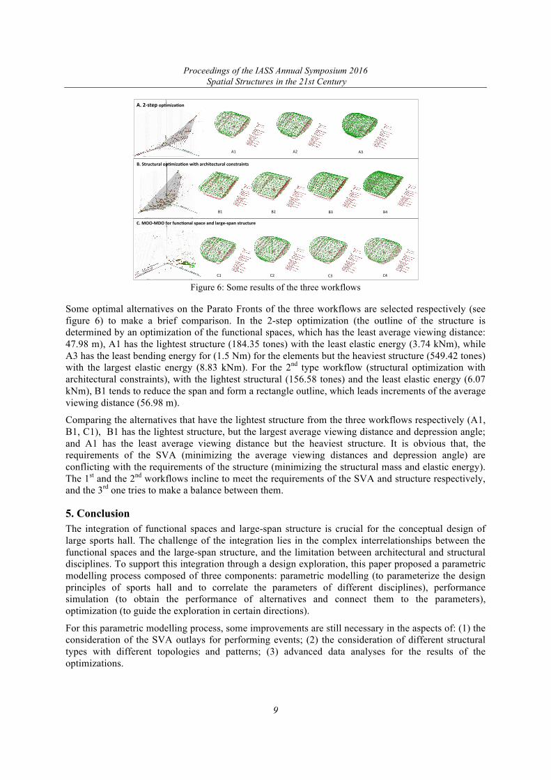
Figure 6: Some results of the three workflows
Some optimal alternatives on the Parato Fronts of the three workflows are selected respectively (see figure 6) to make a brief comparison. In the 2-step optimization (the outline of the structure is determined by an optimization of the functional spaces, which has the least average viewing distance: 47.98 m), A1 has the lightest structure (184.35 tones) with the least elastic energy (3.74 kNm), while A3 has the least bending energy for (1.5 Nm) for the elements but the heaviest structure (549.42 tones) with the largest elastic energy (8.83 kNm). For the 2nd type workflow (structural optimization with architectural constraints), with the lightest structural (156.58 tones) and the least elastic energy (6.07 kNm), B1 tends to reduce the span and form a rectangle outline, which leads increments of the average viewing distance (56.98 m).
Comparing the alternatives that have the lightest structure from the three workflows respectively (A1, B1, C1), B1 has the lightest structure, but the largest average viewing distance and depression angle; and A1 has the least average viewing distance but the heaviest structure. It is obvious that, the requirements of the SVA (minimizing the average viewing distances and depression angle) are conflicting with the requirements of the structure (minimizing the structural mass and elastic energy). The 1st and the 2nd workflows incline to meet the requirements of the SVA and structure respectively, and the 3rd one tries to make a balance between them.
5. Conclusion The integration of functional spaces and large-span structure is crucial for the conceptual design of large sports hall. The challenge of the integration lies in the complex interrelationships between the functional spaces and the large-span structure, and the limitation between architectural and structural disciplines. To support this integration through a design exploration, this paper proposed a parametric modelling process composed of three components: parametric modelling (to parameterize the design principles of sports hall and to correlate the parameters of different disciplines), performance simulation (to obtain the performance of alternatives and connect them to the parameters), optimization (to guide the exploration in certain directions).
For this parametric modelling process, some improvements are still necessary in the aspects of: (1) the consideration of the SVA outlays for performing events; (2) the consideration of different structural types with different topologies and patterns; (3) advanced data analyses for the results of the optimizations.
A.2-stepop+miza+on
C.MOO-MDOforfunc+onalspaceandlarge-spanstructure
B.Structuralop+miza+onwitharchitecturalconstraints
C1 C2 C3 C4
A1 A2 A3
B1 B2 B3 B4
Proceedings of the IASS Annual Symposium 2016 Spatial Structures in the 21st Century
10
Acknowledgement This research was supported by the Key Project of National Natural Science Foundation of China (Grant No. 51138004), the Sports Engineering Development Fund, TU Delft Sports Engineering Institute, the Urban System and Environment (USE) Joint Research Center between SCUT and TU Delft. The first author is sponsored by the scholarship of China Scholarship Council (CSC) for his joint PhD research at Delft University of Technology, Delft, the Netherlands.
References [1] Beghini L., Beghini A., Katz N., Baker W., Paulino G., Connecting architecture and engineering
through structural topology optimization. Journal of Engineering Structures, 2014; 59; 716-726. [2] Cruz P. (ed), Structural and Architectural: Concepts, Application and Challenges, Taylor &
Francis Group, Lindon, 2013. [3] Culley P., Pascoe J., Sports Facilities and Technologies. Routledge, 2009. [4] Delgado J., Hofmeyer H., Automated generation of structural solutions based on spatial designs.
Journal of Automation in Consruction, 2013; 35; 528-541. [5] Football Licensing, Guide to Safety at Sports Grounds. (5th ed.), TSO, 2008. [6] Hines D., Interoperability in Sports Design. Journal of Architectural Design, 2013;83;70-73. [7] Hofmeyer H., Bakker M., Spatial to kinematically determined structural transformations. Journal
of Advance Engineering Informatics, 2008; 22; 393-409. [8] Hudson R., Westlake M., Simulation human visual experience in stadiums, in Society for
Compuater Simulation International 2015. Proceedings of the Symposium on Simulation for Architecture & Urban Design, 2015.
[9] Leach J., Webster T., Nicolin R., Structural engineers as creative leaders–from stadia to pavilions, in IABSE 2015. Symposium Report of IABSE International Association for Bridge and Structural Engineering - Vol. 105, 2015, No. 46.
[10] Lewis C., King M., Designing the world's largest dome: the national stadium roof of the Singapore sports hub. The IES Journal Part A, 2014; 7.3; 127-150.
[11] Mora R., Bedard C., Rivard H., A geometric modelling framework for conceptual structural design from early digital architectural models. Journal of Advanced Engineering Informatics, 2008; 22; 254-270.
[12] Muller C., Ochsendorf J., Combining structural performance and designer preferences in evolutionary design space exploration. Journal of Automation in Construction, 2015; 52; 70-82.
[13] Sports England, Comparative sizes of Sports Pitches & Courts (Indoor), Sports England, 2015. [14] Sports England, Sports Halls: Design and Layouts, Sports England, 2012. [15] The British Standard Institution, BE EN 13200-1:2012 (Spectator facilities. General
characteristics for spectator viewing area), BSI Standard Limited, 2012. [16] Sun Y., Xiong L., Su P., Grandstand grammar and its computer implementation, in eCAADe
2013. Computation and Performance - Proceedings of the 31st eCAADe conference - Volume 2, Stouffs R. and Sariyildiz S. (ed.), 2013, 645-653.
[17] Turrin M. Performance Assessment Strategies: A Computational Framework for Conceptual Design of Large Roofs, Tu Delft, 2014.
[18] Xiong L., Pan W., Sun Y., Integrated computational optimization for the Layout of the playing hall in the gymnasium based on viewing quality analysis, in IASS 2015. Proceedings of IASS 2015, 2015, 554252.
[19] Yang D. Sun Y., Turrin M., von Buelow P., Paul J., Multi-objective and multidisciplinary design optimization of large sports building envelopes: A case study, in IASS 2015. Proceedings of IASS 2015, 2015.
[20] Yang D., Turrin M., Sariyildiz S., Sun Y., Sports building envelope optimization using multi-objective multidisciplinary design optimization (M-MDO) techniques, in IEEE 2015. Proceedings of IEEE CEC2015, 2015, 2269-2278.