A new calibration method for linear CCD camera
7
2010 Symposium on Security Detection and Information Processing A New Calibration Method for linear CCD camera Xia Zhao a *, Bin Liu a , Chunhui Yang a a National Key Laboratory for Electronic Measurement Technology, North University of China Taiyuan, China Abstract The linear CCD camera which applies to micro-image measuring system must have been calibrated before working. The separate calibration method of linear CCD camera’s internal and external orientation parameters is proposed in the paper. The imaging model of the linear camera has been studied, and the equal parallel lines are used to calibrate internal parameters of camera in the experiment where the industrial environment is simulated. In addition, parallel lines and tri-forked stencil are used to calibrate external orientation parameters in the industrial field, such as the attitude angel. The separate calibration method has reduced the calibration task in the industry, and the calibration template is easy to make. The results show that the testing accuracy improves greatly by using the calibrated camera for measuring the gauge, and the calibrated camera can be easily applied to other measurement environment. © 2010 Published by Elsevier Ltd. Keywords: micro-measurement; camera calibration; Linear CCD; separation calibration 1. Introduction The precision measurement system based on the linear CCD is widely used in many fields along with the developed of machine vision, for example, the non-contact measurement, control and classification of products’ on- line test. Many references have proposed some methods to calibrate them [1-3] . However, these calibrating processes are complex and require the auxiliary equipments with high accuracy. This paper achieved the calibration of linear CCD camera in macro-image measurement system on-line. In addition, the amount of work in the industry is * Xia Zhao. . Tel.: +86-0351-3559472 E-mail address: [email protected]. Procedia Engineering 7 (2010) 290–296 www.elsevier.com/locate/procedia 1877-7058 c ⃝ 2010 Published by Elsevier Ltd. doi:10.1016/j.proeng.2010.11.047
Transcript of A new calibration method for linear CCD camera

Available online at www.sciencedirect.com
Procedia Engineering 00 (2010) 000–000
ProcediaEngineering
www.elsevier.com/locate/procedia
2010 Symposium on Security Detection and Information Processing
A New Calibration Method for linear CCD camera
Xia Zhaoa*, Bin Liua, Chunhui Yanga
a National Key Laboratory for Electronic Measurement Technology, North University of China Taiyuan, China
Abstract
The linear CCD camera which applies to micro-image measuring system must have been calibrated before working. The separate calibration method of linear CCD camera’s internal and external orientation parameters is proposed in the paper. The imaging model of the linear camera has been studied, and the equal parallel lines are used to calibrate internal parameters of camera in the experiment where the industrial environment is simulated. In addition, parallel lines and tri-forked stencil are used to calibrateexternal orientation parameters in the industrial field, such as the attitude angel. The separate calibration method has reduced the calibration task in the industry, and the calibration template is easy to make. The results show that the testing accuracy improves greatly by using the calibrated camera for measuring the gauge, and the calibrated camera can be easily applied to other measurement environment.
© 2010 Published by Elsevier Ltd.
Keywords: micro-measurement; camera calibration; Linear CCD; separation calibration
1. Introduction
The precision measurement system based on the linear CCD is widely used in many fields along with the developed of machine vision, for example, the non-contact measurement, control and classification of products’ on-line test. Many references have proposed some methods to calibrate them[1-3]. However, these calibrating processes are complex and require the auxiliary equipments with high accuracy. This paper achieved the calibration of linear CCD camera in macro-image measurement system on-line. In addition, the amount of work in the industry is
* Xia Zhao. . Tel.: +86-0351-3559472 E-mail address: [email protected].
Procedia Engineering 7 (2010) 290–296
www.elsevier.com/locate/procedia
1877-7058 c⃝ 2010 Published by Elsevier Ltd.doi:10.1016/j.proeng.2010.11.047
Xia Zhao/ Procedia Engineering 00 (2010) 000–000
reduced by using the separate calibration method, furthermore, it makes the measuring system can be applied in other measurement conditions.
2. Imaging model
To obtain a model for the interior geometry of a linear CCD camera, we can regard a line sensor as one particular line of an area CCD according to pinhole camera, and the macro-imaging model of linear CCD is attempted to be founded.
2.1 Geometric models In fact, the lens distortion is unavoidable, but with the development of camera making techniques, it only causes
distortions within each row of image if the line sensor is mounted precisely behind the projection center [4], and the motion is purely in the direction of the camera coordinate system ( )0,,0( v ), and the motion is tuned to the line frequency of the camera. Because of the camera’s depth of field (DOF) is much smaller in the micro-version precision measurement [5], the feature dot can be considered to locate the focal plane which perpendicular to the optical axis. And the system belongs to the plane measurement. In the laboratory, the optical axis can be perpendicular to the calibration plane well, that make the world coordinate system (WCS) parallel to the camera coordinate system (CCS).
v =
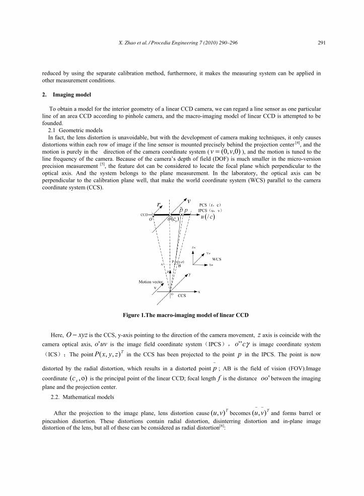
Figure 1.The macro-imaging model of linear CCD
Here, is the CCS, y-axis pointing to the direction of the camera movement, xyzO − z axis is coincide with the camera optical axis, is the image field coordinate system IPCSuvo' γco ''
p is image coordinate system
ICS The point in the CCS has been projected to the point in the IPCS. The point is now
distorted by the radial distortion, which results in a distorted point ; AB is the field of vision (FOV).Image
coordinate is the principal point of the linear CCD; focal length is the distance between the imaging plane and the projection center.
Tzy ),xP ,(~p
f)o,( xc 'oo
2.2. Mathematical models
After the projection to the image plane, lens distortion cause becomes and forms barrel or pincushion distortion. These distortions contain radial distortion, disinterring distortion and in-plane image distortion of the lens, but all of these can be considered as radial distortion[6]:
Tvu ),( Tvu ),(~~
X. Zhao et al. / Procedia Engineering 7 (2010) 290–296 291

Xia Zhao / Procedia Engineering 00 (2010) 000–000
2 2
21 1 4 ( )
uv vk u v
=+ − +
u . (1)
It can also take the distortion correction by:
2 2
11 ( )
uv vk u v
=+ +
u . (2)
Equation (2) can calculate the distortion of lens in u axis. From the perspective projection we have the relation:
2
11( )u x
u uku
u c c sfxuz
=+
= −
=
x . (3)
Here, is the distance between two pixels’ center. We get: xS
2 2
( )1 ( )
u x x
u x x
c c s fxk c c s z
− =+ −
(4)
The DOF of macro-system is so small that can be considered as invariable, these two parameters mix together
to be the enlarging coefficient.
z
zf=β The camera coordinates of x can be computed by:
wx X T= + . (5)
Therefore, the mathematical model of the Imaging system is:
2 2
( )(
1 ( )u x x
wu x x
c c sX T
k c c sβ−
= ++ −
) . (6)
3. Calibration process
Camera calibration is the process of determining the interior and exterior camera parameters. Exterior camera parameters may needs to calibrate many times, but the interior camera parameters only needs to calibrate once. In order to deduce the complexity of calibration in actual application, the parameter separating calibration is adopted, shown in Fig2, relative fixed parameters are calibrated in the laboratory, for example, lens distortion coefficient, principle point coordinate and so on. While the calibrations of the pose angle and translation amount related to the cameras pose are accomplished in the testing scene.
292 X. Zhao et al. / Procedia Engineering 7 (2010) 290–296

Xia Zhao/ Procedia Engineering 00 (2010) 000–000
Figure 2. Calibration process
3.1. The calibration in laboratory The calibrations, principle point coordinate and enlarged coefficient are accomplished in laboratory. The selected
optical plate has parallel lines equal spacing. Based on cross ratio invariance, the plane spanned by the linear CCD and the projection center is intersected with parallel group; meanwhile the distances intercepted between two lines are equal. In fact, they are not equal because of the lens’s distortion. We first consider the case where there are no radial distortions in the center of the image. Then, we archived the solution of initial of some parameters [7]. Finally, the optimal solution of every parameter is obtained through applying the nonlinear regression method using the tested data.
The target points’ world coordinates. The optical plate of the system selection is shown as Fig3. Let us assume that the actual distance between incisures is , these coordinates in them X axis are , shown as the following figure:
)36,...1( =iim
Figure 3. Calibration model
The actual image coordinates of target points. In order to obtain the accurate coordinate value of every parallel line, the right margin of every parallel line is located according to the features of the image. Gray moment operators sub-pixel location algorithm is used to gain the sub-pixel coordinate of every parallel line.
Computation. Taking one-frame images as the studied objects, the image center can be considered without distortion. Equation (6) reduces to:
. (7) ( ) (u x x wc c s X Tβ− = + )
Here, the previous value of is supposed to be the image center, cuis the image coordinate of actual imaging
point. The enlarged coefficientxc ~
β and translation amountT can be estimated from two or more point correspondence which in the center of the image.
Considering distortion factors, Equation (6) suggests that the more coefficients might be used to estimate the optimal solution of the interior orientation parameters though the nonlinear regression method, which conclude the enlarged coefficient β , the accurate coordinate location and distortion coefficient .The working distance of camera
)0,( xc kz should be measured, and the relative focal length is solved. f
3.2. Calibration in working site The calibration of exterior camera parameters is taken in the working site. Keeping the focal length and aperture
of camera’s lens unchanged, we can calibrate the pose parameters pitching angleθ , tilt angleϕ , rotation angle ψ(rotation angle from WCS to CCS), and the translation T . Geometric relations between the camera and the calibration object are necessary to calibrate the exterior parameters and to take a fine adjustment.
The surface of calibrated template must be parallel to the surface of calibration object, and they are in the same measurement environment to make sure the actual work pieces can be measured directly after calibration. Adjusting the working distance of camera to make images clearly, the method of adjusting was adopt gradient vector square algorithm as focusing evaluation function, dealing with images to make the focusing function value reach the maximum.
Pitching angle θ (around the x axis). In the condition that the camera can make the clear images, the pitching angle has a little influence on the measuring precision of every line, only locate leading or lagging θsinz of the measuring point. Since the working distance z is small, the influence of gentle pitching angle to the precision measuring system can be omitted, which needn’t correct.
X. Zhao et al. / Procedia Engineering 7 (2010) 290–296 293

Xia Zhao / Procedia Engineering 00 (2010) 000–000
Tilt angle ϕ (around the axis). The correction of tilt angle still adopts the optical plate which have the parallel lines to calibrate, different from the experimental calibration, the distance between the parallel of calibrated template and the camera have changed, not keeping in
y
z , turns to ϕsin' imzz += . Replacing z by in (6) and substituting these images coordinate into (6), we will get the best tilt angle
'zϕ .
Rotation angle ψ (around the z axis). The rotation angleψ of camera round the optical axis influences the system greatly, which needs precise measurement and adjustment. The tri-forked calibrating template is adopted (Fig.4). OP is the moving direction of camera, and is the angular bisector of , which is doubled with the central line of the measured object. The straight line, CCD located intersection points A D and B with the calibration model.
OP MON∠
Fig 4. The calibration template of rotation angle
From the Sine theorem in the Fig 4, we get:
sin sin
sin sin
AD OD
BD OD
α
α γ
=
=
β . (8)
Then, we have the equations:
sin sin2 2AD BDβ γα β γ π
=+ + =
. (9)
Where the β and γ are unknown, α is the known quantity. The line segments AD and BD can be measured precisely, then we can get the rotation angleψ :
(2π )ψ α β= − + . (10)
The translationT . In order to improve the utilization ratio of linear CCD, the center of measured object should near the principle point of the camera. The angular bisection of the template shown as Fig 4 is doubled with the central line of measured object, so the translation amount is the space distance represented by the coordinate difference between the imaging point D and the principle point coordinate of camera in the IPCS.
OP
( )D x xc c sT . (11) β
−=
According to the exterior orientation parameters, the camera will kept in a good measuring state using the precise mechanical system to adjust the camera pose.
294 X. Zhao et al. / Procedia Engineering 7 (2010) 290–296

Xia Zhao/ Procedia Engineering 00 (2010) 000–000
4. The experimental calibration result
The calibration method discussed in this paper can be applied in the micro-gap measurement system. The linear camera adopts the L100b of the BASLER, the effective pixel is 2048, the parallel template adopted is shown as Fig 3, and the equations is calculated by nonlinear regression method, the interior orientation parameters’ optimal solution of the camera are:
3.8213β = 81.2197 10k −= − ×
1023.742xc pixel= 36z m= m
Note that this also determines the exterior orientation of the calibration target; however, this information is discarded. In the final position, only a few images of the calibration targets are taken and only the exterior orientation is optimized to determine the pose of the camera with respect to the measurement plane.
In the actual measurement, we will realize the distortion correction through (3). We use the calibrated camera to measure the standard gauge which is 0 level and 4mm thickness. The results are given in table 1.
TABLE I. RESULTS WITH REAL DATA OF 4MM GAUGE
Not distortion correction (pixel) distortion correction (pixel) Frame Left edge Right edge difference Left edge Right edge difference
20 245.562 1778.024 1532.462 247.140 1776.645 1529.50540 245.813 1779.018 1533.205 247.326 1777.633 1530.30760 246.163 1778.415 1532.252 247.673 1777.034 1529.39780 245.958 1779.421 1533.463 247.470 1778.034 1530.564100 246.534 1778.330 1531.796 248.043 1776.949 1528.906Average 1532.636 Average 1529.736 Maximum error m 10.7 Maximum error m 2.13 relative error 0.32% relative error 0.053%
5. Conclusion
The separation calibration method of the linear CCD camera was presented in this article. This method can be utilized in various machine vision based linear CCD applications, but it is most beneficial in camera based macro-measurements and in industrial robot vision, where high speed and fine scanning are needed. This uses explicit calibration methods for interior and exterior orientation parameters. The experiments obtained the optimal solution of parameters through nonlinear regression method, the measurement of the gauge indicated that the camera’s precision over 6x accuracy improvement since calibration.
According to the experimental result, the measuring result is stable, the measuring precision of calibrated camera improves a lot, and the error is small.
References
[1] Zhang H.T., Duan F.J., Ding K.Q., et a1. Study on Calibration of Linear CCD Based on Two Steps. ACTA METROLOGICA SINICA 2007; 28(4): 311-3.
[2] Ai L.L.,Yuan F.,Ding Z.L. An exterior attitude measurement system for spatial object based on linear CCD. Optics and Precision Engineering 2008; 16(1):161-5.
[3] Luo W.B.,Wang G.Z.,Ding H.S., et a1. 3-D positioning system based on linear CCD camera. J Tsinghua Univ (Sci&Tech) 2002; 42(9): 1139-43.
[4] C.Steger, M.Ulrich, C.Wiedemann. Machine Vision Algorithms and Applications Wiley-VCH,Berlin,Germany,2008. [5] Jiang Z, Xu D, Tan M, et al. MEMS assembly with the simples focus measure. IEEE International Conference on Robotics and Automation
1999; 1638-43. [6] R Lenz, D Fritsch. Accuracy of videometry with CCD sensors. ISPRS Journal of Photogrammetry and Remote Sensing 1990; 45(2): 90-
110.
X. Zhao et al. / Procedia Engineering 7 (2010) 290–296 295

Xia Zhao / Procedia Engineering 00 (2010) 000–000
[7] Tsai R Y. A versatile camera calibration technique for high-accuracy 3-D machine vision metrology using off- the-shelf cameras and lens. IEEE Transactions on Robotics and Aotomation 1987; 3(4): 323-44.
296 X. Zhao et al. / Procedia Engineering 7 (2010) 290–296