A modified whale optimization algorithm-based adaptive ...
13
Full Terms & Conditions of access and use can be found at http://www.tandfonline.com/action/journalInformation?journalCode=taut20 Automatika Journal for Control, Measurement, Electronics, Computing and Communications ISSN: 0005-1144 (Print) 1848-3380 (Online) Journal homepage: http://www.tandfonline.com/loi/taut20 A modified whale optimization algorithm- based adaptive fuzzy logic PID controller for load frequency control of autonomous power generation systems Raghuraman Sivalingam, Subramani Chinnamuthu & Subhransu Sekhar Dash To cite this article: Raghuraman Sivalingam, Subramani Chinnamuthu & Subhransu Sekhar Dash (2017) A modified whale optimization algorithm-based adaptive fuzzy logic PID controller for load frequency control of autonomous power generation systems, Automatika, 58:4, 410-421, DOI: 10.1080/00051144.2018.1465688 To link to this article: https://doi.org/10.1080/00051144.2018.1465688 © 2018 The Author(s). Published by Informa UK Limited, trading as Taylor & Francis Group. Published online: 22 May 2018. Submit your article to this journal Article views: 136 View Crossmark data
Transcript of A modified whale optimization algorithm-based adaptive ...

Full Terms & Conditions of access and use can be found athttp://www.tandfonline.com/action/journalInformation?journalCode=taut20
AutomatikaJournal for Control, Measurement, Electronics, Computing andCommunications
ISSN: 0005-1144 (Print) 1848-3380 (Online) Journal homepage: http://www.tandfonline.com/loi/taut20
A modified whale optimization algorithm-based adaptive fuzzy logic PID controller forload frequency control of autonomous powergeneration systems
Raghuraman Sivalingam, Subramani Chinnamuthu & Subhransu SekharDash
To cite this article: Raghuraman Sivalingam, Subramani Chinnamuthu & Subhransu Sekhar Dash(2017) A modified whale optimization algorithm-based adaptive fuzzy logic PID controller for loadfrequency control of autonomous power generation systems, Automatika, 58:4, 410-421, DOI:10.1080/00051144.2018.1465688
To link to this article: https://doi.org/10.1080/00051144.2018.1465688
© 2018 The Author(s). Published by InformaUK Limited, trading as Taylor & FrancisGroup.
Published online: 22 May 2018.
Submit your article to this journal
Article views: 136
View Crossmark data

VOL. 58, NO. 4, 410–421https://doi.org/10.1080/00051144.2018.1465688
REGULAR PAPER
Amodified whale optimization algorithm-based adaptive fuzzy logic PIDcontroller for load frequency control of autonomous power generation systems
Raghuraman Sivalingama, Subramani Chinnamuthu b and Subhransu Sekhar Dash b
aDepartment of Electrical and Electronics Engineering, Velammal Engineering College, Chennai, India; bDepartment of Electrical andElectronics Engineering, SRM University, Chennai, India
ABSTRACTAn autonomous power generation system (APGS) contains units such as diesel energy gener-ator, solar photovoltaic units, wind turbine generator and fuel cells along with energy-storingunits such as the flywheel energy storage system and battery energy storage system. The com-ponents either run at lower/higher power output or may turn on/off at different instants of theiroperation. Due to this, the conventional controllers will not provide desired performance undervaried load conditions. This paperproposes anadaptive fuzzy logic PID (AFPID) controller for loadfrequency control. In order to achieve an improved performance, a modified whale optimiza-tion algorithm (mWOA) was also proposed in this paper for tuning of the AFPID parameters. Theproposed algorithm was first evaluated using standard test functions and compared with otherrecent algorithms to authenticate the competence of algorithm. The proposedmWOAalgorithmoutperforms PSO, GSA, DE and FEP algorithms in five out of seven unimodal test functions andfour out of six multimodal test functions. The effectiveness of the AFPID compared with the con-ventional PIDand theproposedAFPIDprovidesbetter performance. Reductionof 39.13% inerrorcriteria (objective function) comparedwithWOA-PID controller. Theproposedapproachwas alsocomparedwith some recently proposed frequency control approaches in awidely used two-areatest system.
ARTICLE HISTORYReceived 22 December 2017Accepted 11 April 2018
KEYWORDSAutonomous powergeneration system; loadfrequency control (LFC);whale optimizationalgorithm (WOA); adaptivefuzzy logic PID controller(AFPID)
1. Introduction
The increasing power demand, rising costs of electric-ity transmission and distribution, deregulation of theenergy markets, depletion of fossil fuels are making asignificant entrance of renewable energy resources intothe energy sector [1–4]. The centralized power gen-eration, transmission and distribution are now shift-ing to a decentralized one [1]. In this framework, anew power system model called autonomous powergenerating system (APGS) has evolved. It is a collec-tion of distributed energy resources (DERs) such asdiesel energy generator (DEG), fuel cell (FC), micro-turbine generator (MTG) with solar photovoltaic (PV)units and wind turbine generators (WTG) and clus-ter of loads [1,2]. The chaotic characteristics of theload and the sustainable energy generations, i.e. windand solar sources, introduce fluctuations in the systemfrequency [1]. Energy-storing elements such as ultracapacitor (UC), flywheel energy storage system (FESS)and battery energy storage system (BESS) are coupledto the system to mitigate the unbalance due to genera-tion and load mismatch. These energy-storing devicesstore the surplus power for a small interval of periodfrom the renewable energy sources and later deliver the
power to the grid when there is a more load demand[5,6]. A proper control strategy is required for coordi-nating these actions accurately [5]. This calls for theconcept of load frequency control (LFC) for dampingthe frequency oscillation.
To enhance the LFCperformance, several approachessuch as the conventional PID controller [4,7], robustH∞ controller [8–11], fractional order controller[1,5,6] have been used in similar types of system design.To preserve desirable performance and stability, eithercentralized controller [6] or decentralized controller [4,12] is used. The system parameters and the local loadsof the hybrid power system controlled by a centralizedcontrol unit rather than multiple decentralized con-trollers make the overall system design simple as wellas reduce cost [1]. Conventional PI-based controller hasbeen adopted by the researcher for LFC on similar typesof system [4,7]. RobustH∞ controller approaches havebeen widely proposed in the literature for LFC problem[3,9–11]. Few papers addressed fuzzy logic techniquesfor optimal tuning of the standard PID controller[13–15] and FOPID controller [5] for solving LFCproblem. It is observed that adaptive control makes thesystem under control less affected by the unmodelled
CONTACT Raghuraman Sivalingam [email protected] Department of Electrical and Electronics Engineering, Velammal EngineeringCollege, Chennai, India
© 2018 The Author(s). Published by Informa UK Limited, trading as Taylor & Francis Group.This is an Open Access article distributed under the terms of the Creative Commons Attribution License (http://creativecommons.org/licenses/by/4.0/), which permits unrestricteduse, distribution, and reproduction in any medium, provided the original work is properly cited.
AUTOMATIKA, 2017

AUTOMATIKA 411
process dynamics and variation in system parameters.Therefore, in the proposed control strategy, an adaptivefuzzy-based PID controller is taken into considerationfor LFC in the proposed hybrid power system.
Controlling APGS with various uncertain systemparameters is mostly based on optimization [6]. Differ-ent types of hybrid algorithms were developed in manypapers [1,5,7,8,11,13] to find the controller gains inorder to enhance the system transient response as wellas to ensure the robustness and stability of the system.Many researchers have suggested different optimizationtechniques such as fast evolutionary algorithm [16],Glowworm Swarm Optimization [17], multi-objectiveevolutionary algorithm [18], microgenetic algorithm[19], hybrid differential evolution and harmony searchalgorithm [20], clustered adaptive teaching learning-based optimization [21] in power system problems.Whale optimization algorithm (WOA) is a recently pro-posed technique inspired by hunting the behaviourof whales [22]. The major benefit of the WOA tech-nique compared to other established techniques is thatthe WOA technique does not need specific algorithmparameters. Apart from this, WOA is easy to under-stand and program. The algorithm uses three oper-ators: the hunt for prey, surrounding the prey andbubble-net searching behaviour of whales for optimiza-tion. The superiority of WOA over PSO, GSA, DE andFEP has been demonstrated [22]. However, in origi-nal WOA algorithm, the present best solution is thetarget prey and the others attempt to modify their posi-tions towards the best agent. This process of updatemay result in being stuck in local optima. Therefore,in the present paper, a modified whale optimizationalgorithm (mWOA) is proposed where correction fac-tors are introduced at various stages of the algorithmto get improved results. After this, the mWOA tech-nique is used to tune AFPID (adaptive fuzzy logicPID) controller parameters; results are compared withWOA and mWOA optimized PID controller. Devia-tion in grid frequency, control signal and the output ofdifferent controlled sources of APGS system are anal-ysed with standard PID and AFPID controllers and thesuperiority of the AFPID over PID is demonstrated.
2. Whale optimization algorithm
WOA is a recently proposed meta-heuristic algorithmbased on social behaviour of whales [8]. Humpbackwhales are among the biggest whales whose favouriteprey are krill and small fish herds. The hunting processof humpback whales is based on the bubble-net feedingapproach method. The twisting bubble-net nourishingscheme is mathematically modelled in WOA. Here thescientific model of encircling prey, spiral bubble-netencouraging move and scan for prey is mathematicallyexpressed.
2.1. Encircling prey
Humpback whale encircles the prey (small fishes); atthat point. overhauls its position towards the optimumsolution over the course of increasing number of itera-tions from start to a maximum number of iterations.
⇀
D =∣∣∣⇀
C · ⇀
X∗(t) − ⇀
X(t)∣∣∣ , (1)
⇀
X(t + 1) = ⇀
X∗(t) − ⇀
A · �D, (2)
where t shows the current iteration, �A and �C are coef-ficient vectors, �X is the position vector of the bestarrangement acquired in this way, �X∗ is the positionvector, · is the element by element multiplication and| | is the absolute value. It merits saying here that �X∗should be upgraded in every cycle if there is a superiorsolution.
�A = 2�a · �r − �a, (3)
�C = 2 · �r, (4)
where �a is linearly decreased from 2 to 0 over the courseof iterations and �r is a random vector in [0, 1].
2.2. Bubble-net attacking technique
Here two methodologies are planned as follows:1. Shrinking encirclingmechanism: This behaviour
is accomplished by diminishing the estimation of �a inEq. (3). Take note of that the fluctuation range of �A islikewise diminished by�a. As such, �A will be a randomvalue in the interim [−a, a] where a is diminished from2 to 0 throughout cycles. Random values for a vector �Aare set in the range between [−1, 1].
2. Spiral updating arrangement: Spiral conditionfor position update between humpback whale and preythat was helix-formed development given as takes after
�X(t + 1) = �D′ · ebl · cos(2π l) + �X∗(t), (5)
where �D′ = |�X∗(t) − �X(t)| and shows the separation ofthe ith whale to the prey (best arrangement got as such),b is a steady to define the state of the logarithmic spiral;dot (·) is a component by component augmentation andl is an arbitrary number in the range [−1, 1].
To model so, we are assuming that there is a likeli-hood of picking a half between either the contractingsurrounding system or the spiral model to overhaul theposition of whales during enhancement. The scientificmodel is as per the follows:
�X(t + 1) ={�X∗(t) − �A · �D, if P < 0.5,D′ · ebl · cos(2π l) + �X∗(t), if P ≥ 0.5,
(6)where P is an arbitrary number in the range [0,1].

412 R. SIVALINGAM ET AL.
2.3. Search for prey (exploration phase)
The �A vector can be utilized for exploration to searchfor prey; vector �A additionally takes the qualities morenoteworthy than one or not asmuch as−1. Explorationtakes after the following two conditions:
�D = �C · −−→Xrand − �X, (7)
�X(t + 1) = −−→Xrand − �A · �D, (8)
where −−→Xrand is an arbitrary position vector (an irreg-ular whale) looked over the present population andcalculated as when |�A| > 1, authorized investigation toWOA calculation to find worldwide ideal avoids localoptima and when |�A| < 1, for overhauling the positionof current search operator/best arrangement is chosen.
3. Modified whale optimization algorithm
In original WOA algorithm, the present best solutionis the target for other search agents. Hence all preyattempt to modify their positions to proximate the bestagent as per Equations (1) and (2). As the location of thebest search, space is not known a priori, this process ofupdate may result in being trapped in local optima. Ifthe position of the vectors changes during the search,the process is governed by large steps, the algorithmmay not be able to explore properly the search space.To minimize the magnitude of changes in the posi-tion of vectors, correction factors are introduced as CF1and CF2 in the proposed mWOA technique. Now theequation becomes
⇀
D =∣∣∣⇀
C · ⇀
X∗(t) − ⇀
X(t)∣∣∣ /CF1, (9)
⇀
X(t + 1) = (⇀
X∗(t) − ⇀
A · �D)/CF1. (10)
The correction factor makes the whales to move insmall steps towards the prey to explore the search spaceefficiently.
Similarly, a correction factor is introduced in theexploitation phase where the spiral updating positionis given by Equation (11) as
�X(t + 1) = (�D′ · ebl · cos(2π l) + �X∗(t))/CF2. (11)
By introducing the above correction factor, the hump-back whales are made to swim around the prey within a
reduced shrinking circle, thus enhancing the exploitingcapability of the algorithm.
Finally, the correction factor is introduced in theexploration phase of search for prey. So in originalWOA algorithm, the search agent position is updatedin the exploration phase as per Equations (7) and (8).As a result, it may lead to randommovement of whales.Thus in the proposed mWOA technique, the positionof search agents is updated by using correction factorsas given in Equations (12) and (13).
�D = (�C · −−→Xrand − �X)/CF1, (12)
�X(t + 1) = (−−→Xrand − �A · �D)/CF2. (13)
After a repeated series of trail runs, the correctionfactors are 2.5and 1.5, respectively.
It should be noted that by introducing the correctionfactors, the capability of whales to reach any positionin the search space is enhanced. Therefore, it allowsany search agent to update its position in the neigh-bourhood of the current best solution and simulatesencircling the prey more efficiently.
4. Performance investigation of mWOAalgorithm
The proposed mWOA algorithm performance is car-ried out by fitting to some standard benchmarkfunctions. The details about these functions, theirdimension, boundary of the search spaces and opti-mum values are available in the literature [22]. Thereare 13 functions, out of which functions f1 tof7 areunimodal functions. Unimodal functions are specifi-cally taken for verifying the exploitation property ofthe algorithm [22]. Functions f8 to f13 are multimodalfunctions with more number of local optima. Thisnumber increases exponentially with the increase indimensions. These functions are very challenging testbeds for meta-heuristic algorithms as exploration andexploitation are tested simultaneously by these func-tions. As suggested in the original WOA algorithm, themWOA algorithm is executed for 30 independent runswith randomly generated population for each bench-mark functions with a population size of 30 and an
Table 1. Statistical result of proposed modified WOA and comparison with other techniques [22] for unimodal benchmark testfunctions.
mWOA WOA PSO GSA DE FEP
f Avg. Std. dev. Avg. Std. dev. Avg. Std. dev. Avg. Std. dev. Avg. Std. dev. Avg. Std. dev.
f 1 0 0 1.41E–30 4.91E–30 0.000136 0.000202 2.53E–16 9.67E–17 8.2E–14 5.9E–14 0.00057 0.00013f 2 0 0 1.06E–21 2.39E–21 0.042144 0.045421 0.055655 0.194074 1.5E–09 9.9E–10 0.0081 0.00077f 3 0 0 5.39E–07 2.93E–06 70.12562 22.11924 896.5347 318.9559 6.8E–11 7.4E–11 0.016 0.014f 4 0 0 0.072581 0.39747 1.086481 0.317039 7.35487 1.741452 0 0 0.3 0.5f 5 28.7801 0.2426 27.86558 0.763626 96.71832 60.11559 67.54309 62.22534 0 0 5.06 5.87f 6 5.4912 0.5014 3.116266 0.532429 0.000102 8.28E–05 2.5E–16 1.74E–16 0 0 0 0f 7 0.1396E–4 0.144E–4 0.001425 0.001149 0.122854 0.044957 0.089441 0.04339 0.00463 0.0012 0.1415 0.3522
AUTOMATIKA 413
Table 2. Statistical result of proposed modified WOA and comparison with other techniques [22] for multimodal benchmark testfunctions.
mWOA WOA PSO GSA DE FEP
f Avg. Std. dev. Avg. Std. dev. Avg. Std. dev. Avg. Std. dev. Avg. Std. dev. Avg. Std. dev.
f 8 −2.2973E3 0.4074E3 −5080.76 695.7968 −4841.29 1152.814 −2821.07 493.0375 −11080.1 574.7 −12554.5 52.6f 9 0 0 0 0 46.70423 11.62938 25.96841 7.470068 69.2 38.8 0.046 0.012f 10 4.086E–15 1.084E–15 7.4043 9.897572 0.276015 0.50901 0.062087 0.23628 9.7E–08 4.2E–08 0.018 0.0021f 11 0 0 0.000289 0.001586 0.009215 0.007724 27.70154 5.040343 0 0 0.016 0.022f 12 0.1815 0.1162 0.339676 0.214864 0.006917 0.026301 1.799617 0.95114 7.9E–15 8E–15 9.2E–06 3.6E–06f 13 1.8095 0.1236 1.889015 0.266088 0.006675 0.008907 8.899084 7.126241 5.1E–14 4.8E–14 0.00016 0.000073
iteration of 500. Tables 1 and 2 show results like aver-age and standard deviation for unimodal and multi-modal functions, respectively. The proposed mWOAalgorithm results were compared with the originalWOA algorithm and with some recent well-knownmeta-heuristic techniques such as PSO, GSA, DE andFEP [22]. It is evident from Table 1 that, for unimodalmodal functions,mWOAtechnique is very efficient andoutperformsWOA, PSO, GSA, DE and FEP for five (f 1,f 2, f 3, f 4, f 7) out of seven unimodal test functions. It isobserved fromTable 2 that,mWOAoutperformsWOA,PSO, GSA, DE and FEP for four (f 8, f 9, f 10, f 11) outof six unimodal test functions. This validates that themodified WOA makes a sound equilibrium betweenexploration and exploitation preventing local optima
stagnation. The proposed mWOA technique was thenapplied to a real-world problem of tuning the AFPID.
5. System investigated
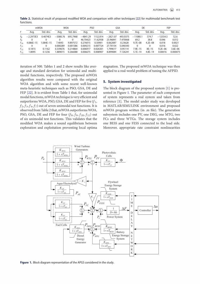
The block diagram of the proposed system [1] is pre-sented in Figure 1. The parameter of each componentof system represents a real system and taken fromreference [1]. The model under study was developedin MATLAB/SIMULINK environment and proposedmWOA program written (in .m file). The generationsubsystem includes one PV, one DEG, one MTG, twoFCs and three WTGs. The storage system includesone BESS and one FESS connected to the load side.Moreover, appropriate rate constraint nonlinearities
Figure 1. Block diagram representation of the APGS considered in the study.

414 R. SIVALINGAM ET AL.
Table 3. Parameters of APGS [1].
Components Gain Time constant
Solar photovoltaic (PV) KPV = 1 TPV = 1.8Wind turbine generator (WTG) KWTG = 1 TWTG = 1Aqua electrolyser (AE) KAE = 0.002 TAE = 0.5Fuel cell (FC) KFC = 0.01 TFC = 4Diesel energy generator (DEG) KDEG = 0.003 TDEG = 2Battery energy storage system (BESS) KBESS = −0.003 TBESS = 0.1Flywheel energy storage system (FESS) KFESS = −0.01 TFESS = 0.1Micro turbine generator (MTG) KMTG = 0.002 TMTG = 1
were considered such as |PFESS| < 0.9, |PBESS| < 0.2,|PDEG| < 0.01, |PMTG| < 0.01. These rate constraintnonlinearities incorporate various electromechanicalconstraints that these devices exhibit.
5.1. Modelling of different generation system
The PV, DEG, MTG, FC and WTG are representedin Equations (14)–(18) with their corresponding gainsand time constants reported in Table 3 [1,3,4]. Theparameter k represents the number of units considered.
GPV(s) = KPV
(1 + sTPV)= �PPV
�ϕ, (14)
GDEG(s) = KDEG
(1 + sTDEG)= �PDEG
�u, (15)
GMTG(s) = KMTG
(1 + sTMTG)= �PMTG
�u, (16)
GFCK(s) = KFC
(1 + sTFC)= �PFC
�PAE, k = 1, 2, (17)
GWTGk(s) = KWTG
(1 + sTWTG)= �PWTG
�PW, k = 1, 2, 3.
(18)
5.1.1. Wind speedmodellingThewind turbine generator power (PWTG) is a functionof wind speed VW. The algebraic summation of basewind speed with noise component [1] is called as windspeed.
VW can be represented by
Vw = VWB + VWN. (19)
The base component of the wind speed is a constantwhich is present throughout thewind turbine operationand for the present case it is taken as 7.5 m/s. It is givenas follows:
VWB = 7.5ϕ(t) − 3ϕ(t − 200) + 10.5ϕ(t − 250),(20)
where ϕ(t) is the Heaviside step function.
The wind speed noise is given as follows:
VWN = 2σ 2N∑i=1
√SV(ωi)�ω cos(ωit + ϕi), (21)
whereωi = (i − 1/2)�ω and ϕi ≈ U(0, 2π).�ω is thechange in frequency to estimate spectral density. σ 2 isthe variance due to noise and set to 200.
The spectral density function Sv(ωi) is expressedin (22)
Sv(ωi) = 2KNF2|ωi|
π2[1 +
(Fωi
Fωiμπ
)2]4/3 , (22)
where N = 50 and �ω = 0.5 rad/s are considered toget an operative modelling precision. KN (=0.004),µ (=7.5) and F (=2000) denote the surface drag coef-ficient, the base wind speed and the turbulence scale,respectively.
5.1.2. Wind turbine characteristicThe power coefficient of wind turbine (CP) [1] is char-acterized by non-dimensional curves which is a func-tion of blade pitch angle (β) and tip speed ratio (λ).
λ is given by
λ = Rbladeωblade
Vw(23)
where Rblade (=23.5 m) and ωblade (=3.14 rad/s)are the blade radius and blade rotational speed,respectively.
Considering β = 0.1745, Cp is given by
Cp = (0.44 − 0.0167β) sin[
π(λ − 3)15 − 0.3β
]
− 0.0184(λ − 3)β . (24)
The wind turbine output [1] is given by
Pw = 12ρArCpV3
w, (25)
where Ar = 1735m2 is the blade swept area andρ = 1.250 kg/m2 is the density of air.
5.1.3. Characteristic of PV system output powerThe PV system output power of [1] is given by
Ppv = ηSγ [1 − 0.005(T + 25)], (26)
where η is the efficiency of the PV cells (η = 10%).S is the area of the PV array (S = 4084m2), γ is thesolar radiation on the PV cells in kw/m2 and T is theambient temperature (T = 25°C).
φ is given by
ϕ = 0.5ϕ(t) − 0.33ϕ(t − 25) + 0.3ϕ(t − 75)
− 0.3ϕ(t − 150) + ϕn(t),
ϕn(t) ≈ U(−0.1, 0.1). (27)

AUTOMATIKA 415
5.2. Modelling of aqua electrolyser
A portion of output power developed by wind andphotovoltaic is used by an aqua electrolyser (AE). It pro-duces hydrogen which is used by FC to produce power.AE uses a fraction, i.e. (1 − kn) of the total power gener-ated fromPV andWTG for the production of hydrogenwhich is fed to the two FCs to produce power. Thetransfer function of the AE can be sighted as
GAE(s) = KAE
(1 + sTAE). (28)
kn is taken as 0.6 for the present study.
5.3. Modelling of energy-storing system
Energy-storing components effectively absorb/supplydeficit/surplus energy from/to the hybrid power systemwithin a fraction of period for a stable hybrid system[1,4].
FESS and BESS are two storage systems consideredin the present study and are expressed as
GFESS(s) = KFESS
(1 + sTFESS)(29)
GBESS(s) = KBESS
(1 + sTBESS). (30)
Each energy storage element is provided with anupper and lower saturation limit along with rate con-straint nonlinearity to prevent the mechanical shockdue to sudden frequency variation [6]. Their rate con-straint nonlinearities are |PFESS| < 0.9, |PBESS| < 0.2and 0 < PDEG < 0.45.
5.4. Power systemmodel
The power system model is formulated as
Gsys(s) = �f�Pe
= 1Ms + D
, (31)
where D and M are equivalent damping constant (0.4)and inertia constant (0.03) of the hybrid power system,respectively. It is taken as 0.4 and 0.03 respectively forthe present study.
6. Adaptive fuzzy logic control
A fuzzy logic controller has a predefined set of con-trol rules, which depends on the researcher’s knowl-edge and experience [23]. The input/output linguisticvariables of the membership functions (MFs) are alsogenerally predetermined. The design of FLCs largelydepends on the choice of input/output scaling factors(SFs) and selection of controller parameters. Tuning ofSFs is of highest importance because of their universaleffect on the control action.
For satisfactory control action, the membershipfunctions should be a function of error (e) and changeof error (�e) and FLC maps input to output by a lim-ited number of IF–THEN rules. Sometimes, this is notadequate to provide necessary control actions. In suchcases, static values of SFs and single MFs are insuffi-cient to achieve the desired control action. To overcomethis, various online and offlinemethods are proposed tofine-tune the input/output SFs to change the definitionof MFs.
Adaptive control has been a topic of research for var-ious LFC schemes. Adaptive control technique is cat-egorized into two types, the self-tuning regulators andthemodel reference control systems [24]. Adaptive con-troller makes the system under control less sensitive toits parameter uncertainties under various environmen-tal and operating conditions. Adaptive fuzzy-based PIDcontroller design has now been considered as a topic ofresearch and several methods are adopted in [14] and[24]. In the proposed method, an adaptive PID kindFLC (AFPID) is used to get the process optimally con-trolled based on the e and �e. Figure 2 represents theschematic diagram of the proposed AFPID controller.
Figure 2. Structure of the proposed adaptive fuzzy logic control scheme.
416 R. SIVALINGAM ET AL.
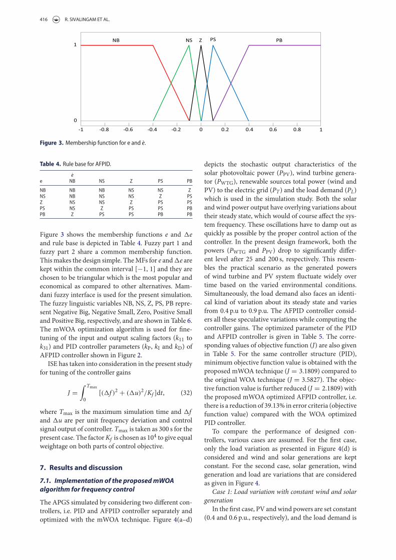
Figure 3. Membership function for e and e.
Table 4. Rule base for AFPID.
ee NB NS Z PS PB
NB NB NB NS NS ZNS NB NS NS Z PSZ NS NS Z PS PSPS NS Z PS PS PBPB Z PS PS PB PB
Figure 3 shows the membership functions e and �eand rule base is depicted in Table 4. Fuzzy part 1 andfuzzy part 2 share a common membership function.Thismakes the design simple. TheMFs for e and�e arekept within the common interval [−1, 1] and they arechosen to be triangular which is the most popular andeconomical as compared to other alternatives. Mam-dani fuzzy interface is used for the present simulation.The fuzzy linguistic variables NB, NS, Z, PS, PB repre-sent Negative Big, Negative Small, Zero, Positive Smalland Positive Big, respectively, and are shown in Table 6.The mWOA optimization algorithm is used for fine-tuning of the input and output scaling factors (k11 tok31) and PID controller parameters (kP, kI and kD) ofAFPID controller shown in Figure 2.
ISE has taken into consideration in the present studyfor tuning of the controller gains
J =∫ Tmax
0[(�f )2 + (�u)2/Kf ]dt, (32)
where Tmax is the maximum simulation time and �fand �u are per unit frequency deviation and controlsignal output of controller. Tmax is taken as 300 s for thepresent case. The factorKf is chosen as 104 to give equalweightage on both parts of control objective.
7. Results and discussion
7.1. Implementation of the proposedmWOAalgorithm for frequency control
The APGS simulated by considering two different con-trollers, i.e. PID and AFPID controller separately andoptimized with the mWOA technique. Figure 4(a–d)
depicts the stochastic output characteristics of thesolar photovoltaic power (PPV), wind turbine genera-tor (PWTG), renewable sources total power (wind andPV) to the electric grid (PT) and the load demand (PL)which is used in the simulation study. Both the solarand wind power output have overlying variations abouttheir steady state, which would of course affect the sys-tem frequency. These oscillations have to damp out asquickly as possible by the proper control action of thecontroller. In the present design framework, both thepowers (PWTG and PPV) drop to significantly differ-ent level after 25 and 200 s, respectively. This resem-bles the practical scenario as the generated powersof wind turbine and PV system fluctuate widely overtime based on the varied environmental conditions.Simultaneously, the load demand also faces an identi-cal kind of variation about its steady state and variesfrom 0.4 p.u to 0.9 p.u. The AFPID controller consid-ers all these speculative variations while computing thecontroller gains. The optimized parameter of the PIDand AFPID controller is given in Table 5. The corre-sponding values of objective function (J) are also givenin Table 5. For the same controller structure (PID),minimum objective function value is obtained with theproposed mWOA technique (J = 3.1809) compared tothe original WOA technique (J = 3.5827). The objec-tive function value is further reduced (J = 2.1809) withthe proposed mWOA optimized AFPID controller, i.e.there is a reduction of 39.13% in error criteria (objectivefunction value) compared with the WOA optimizedPID controller.
To compare the performance of designed con-trollers, various cases are assumed. For the first case,only the load variation as presented in Figure 4(d) isconsidered and wind and solar generations are keptconstant. For the second case, solar generation, windgeneration and load are variations that are consideredas given in Figure 4.
Case 1: Load variation with constant wind and solargeneration
In the first case, PV andwind powers are set constant(0.4 and 0.6 p.u., respectively), and the load demand is

AUTOMATIKA 417
Figure 4. (a) Generated power by solar energy; (b) generated power by wind energy source; (c) total renewable power generation;(d) load demand which are independent of the controller structure.
Table 5. WOA- and mWOA-based tuning parameters of PID and AFPID controllers.
Technique/Controller kP kI kD k11 k21 k31 J
WOA: PID 8.8219 7.1508 4.4308 – – – 3.5827mWOA: PID 9.2701 9.5176 1.8736 – – – 3.1809mWOA: AFPID 4.8406 6.9087 0.2231 1.5893 1.6064 0.9664 2.1809
varied as shown in Figure 4(d). The frequency deviationfor the above case is shown in Figure 5 from which itis clear that the mWOA optimized PID controller pro-vides better system compared to the WOA optimizedPID controller. It can be seen from Figure 5 that themaximum overshoot and undershoot with the WOAoptimized PID controller are 0.3221 and −0.3599 andthe same with themWOAoptimized PID controller are0.3079 and −0.3645, respectively. It is also clear fromFigure 5 that the best system response is obtained withthe proposedmWOA optimized FAPID controller. Themaximum overshoot and undershoot reduce to 0.2697and −0.1878 respectively with the mWOA optimizedFAPID controller.
Case 2: Simultaneous variation of load demand, windand solar power
In case 2, PV and wind powers varied as shown inFigure 4(a,b) along with the load variation. The sys-tem frequency response and control signal responseare shown in Figure 6(a,b) respectively. For compari-son, the responses with WOA optimized PID, mWOAoptimized PID and mWOA optimized AFPID con-trollers are provided in Figure 6. From Figure 6(a) itis clear that the proposed mWOA optimized AFPIDcontroller structure provides better system dynamicresponse compared to theWOAandmWOAoptimizedconventional PID control structure. It can be seenfrom Figure 6(a) that maximum overshoots withWOA
Figure 5. Frequency deviation response under load variation with constant wind and solar power.
418 R. SIVALINGAM ET AL.
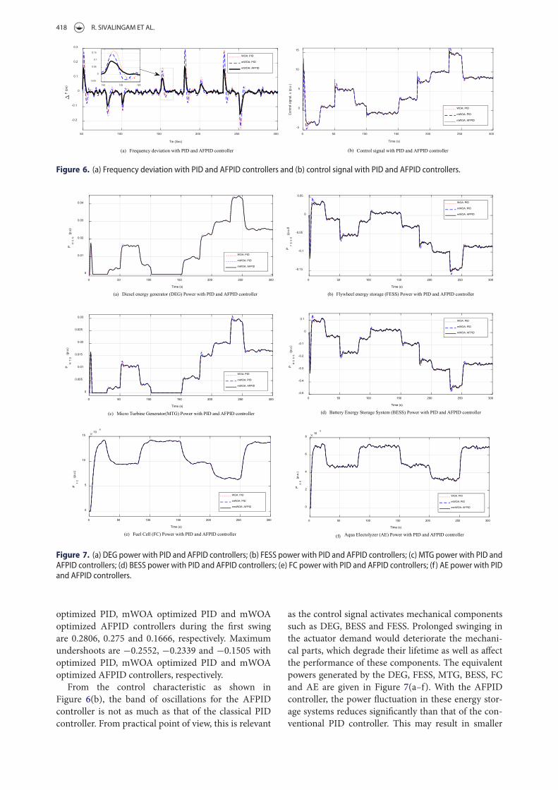
Figure 6. (a) Frequency deviation with PID and AFPID controllers and (b) control signal with PID and AFPID controllers.
Figure 7. (a) DEG power with PID and AFPID controllers; (b) FESS power with PID and AFPID controllers; (c) MTG power with PID andAFPID controllers; (d) BESS power with PID and AFPID controllers; (e) FC power with PID and AFPID controllers; (f ) AE power with PIDand AFPID controllers.
optimized PID, mWOA optimized PID and mWOAoptimized AFPID controllers during the first swingare 0.2806, 0.275 and 0.1666, respectively. Maximumundershoots are −0.2552, −0.2339 and −0.1505 withoptimized PID, mWOA optimized PID and mWOAoptimized AFPID controllers, respectively.
From the control characteristic as shown inFigure 6(b), the band of oscillations for the AFPIDcontroller is not as much as that of the classical PIDcontroller. From practical point of view, this is relevant
as the control signal activates mechanical componentssuch as DEG, BESS and FESS. Prolonged swinging inthe actuator demand would deteriorate the mechani-cal parts, which degrade their lifetime as well as affectthe performance of these components. The equivalentpowers generated by the DEG, FESS, MTG, BESS, FCand AE are given in Figure 7(a–f). With the AFPIDcontroller, the power fluctuation in these energy stor-age systems reduces significantly than that of the con-ventional PID controller. This may result in smaller

AUTOMATIKA 419
Figure 8. Frequency deviation of area 1 under step load disturbance in area 1 for a two-area non-reheat test system with differentAGC approaches.
Table 6. Comparative performance indexes with recent AGC approaches.
Settling times Ts (s)
Performance/technique: control structure ITAE value (×10−2) �F1 �F2 Maximum overshoot Maximum undershoot
Conventional ZN: PI [25] 375.68 45 45 18.25× 10⁻² 31.32× 10⁻³
GA: PI [25] 274.75 10.59 11.39 0 24.07× 10⁻²
BFOA: PI [25] 179.75 5.52 7.09 63.12× 10⁻⁴ 26.21× 10⁻²
DE: PI [26] 125.51 8.96 8.16 20.26× 10⁻³ 23.6× 10⁻²
PSO: PI [27] 121.42 7.37 7.82 38.58× 10⁻³ 25.35× 10⁻²
hBFOA-PSO: PI [27] 118.65 7.39 7.65 36.73× 10⁻³ 24.72× 10⁻²
NSGA-II: PI [28] 117.85 6.49 7.54 67.34× 10⁻⁴ 26.32× 10⁻²
PS: Fuzzy PI [29] 63.34 6.05 7.10 0 92.08× 10⁻³
PSO: Fuzzy PI [29] 44.70 5.13 6.22 0 88.01× 10⁻³
NSGA-II: PIDF [28] 38.7 3.03 4.86 0 105.18× 10⁻³
hPSO-PS: Fuzzy PI [29] 14.38 2.26 3.74 0 85.18× 10⁻³
Proposed mWOA: AFPID 7.33 2.19 2.13 0 38.08× 10⁻³
dimension of this energy storage and supply systems.There is also less requirement of storing and supply-ing power to suppress the grid frequency variation. InFigure 7, negative powers in energy storage elementsindicated that they are absorbing power and converselythe positive powers signify that they are producing theextra power making the whole system stable. Thus thehybrid power system becomesmore reliable and energyefficient.
7.2. Comparisonwith recent frequency controlapproaches
To demonstrate the superiority of the proposedmWOAoptimized AFPID controller, a widely used two equalarea non-reheat thermal power system [25–29] is con-sidered. Identical AFPID controllers are assumed foreach area and the proposed mWOA algorithm wasemployed to tune the controller parameters. For a faircomparison, identical power systemandobjective func-tions from the literature [25–29] are considered. Theoptimized AFPID controller parameters are:
kP = 1.9698, kI = 1.7634, kD = 1.0609,
k11 = 0.8172, k21 = 0.0777, k31 = 1.8405.
A step increase in demand of 10% applied at t = 0 s;in area 1 and the performance of proposed controller
is compared with approaches such as ZN: PI, GA: PI,BFOA: PI [25], DE: PI [26], hybrid BFOA-PSO: PI [27],NSGA-II: PI [28], NSGA-II: PIDF [28], PS: Fuzzy PI[29], PSO: Fuzzy PI [29] and hybrid PSO-PS: FuzzyPI [29]. The results are provided in Table 6. It is clearfrom Table 6 that best system performance with mini-mum ITAE value and settling times in �F1, �F2 and�Ptie are obtained with the proposed mWOA tunedAFPID controller compared to recently proposed AGCapproaches. For completeness, the frequency responseof area 1 for the above disturbance is shown in Figure 8.It is evident from Figure 8 that the proposed approachoutperforms than recently proposed AGC approaches.The maximum overshoots and undershoots of fre-quency response are shown in Figure 8 and tabulated inTable 6. From Table 6, the lowest maximum overshootsand undershoots of frequency response are obtainedwith the proposedmWOAoptimizedAFPID comparedto other approaches.
8. Conclusion
In practice, classical PID controller is commonly usedfor LFC problem. However, it is not able to pro-vide desirable performance during severe disturbances.Owing to the practical difficulties faced in trying toachieve desired control criteria in LFC, an adaptivefuzzy logic PID control method is presented in this

420 R. SIVALINGAM ET AL.
paper for hybrid power systems. For tuning the con-troller parameters, a modified WOA technique is pro-posed where the position of search agents is updatedby using correction factors. It is found from the sta-tistical results that the proposed mWOA algorithmoutperforms original WOA, PSO, GSA, DE and FEPalgorithms. In the next stage, frequency control of anAPGS consisting of various energy sources such asDEG, FC, MTG with renewable energy sources such asPV units, WTG along with energy storage devices likeBESS and FESS and cluster of loads is considered andthe parameters of proposed AFPID controller are opti-mized employing the mWOA technique. It is observedthat themWOA tunedAFPID controller provides supe-rior performance compared to the PID controller. Test-ing the results of mWOA in terms of statistical analysislike “Wilcoxon Signed Rank Test” is the focus of thefuture work. Also, frequency control in an APGSs inthe presence of plug in electric vehicles is the focus ofthe future research work.
Disclosure statement
No potential conflict of interest was reported by the authors.
ORCID
Subramani Chinnamuthu http://orcid.org/0000-0002-3745-2348Subhransu Sekhar Dash http://orcid.org/0000-0003-0861-8035
References
[1] Pan I, Das S. Fractional order AGC for distributedenergy resources using robust optimization. IEEE TransSmart Grid. 2016;7(5):2175–2186.
[2] Ray P, Mohanty S, Kishor N. Small-signal analysisof autonomous hybrid distributed generation systemsin presence of ultracapacitor and tie-line operation.J Electr Eng. 2010;61(4):205–214.
[3] Lee DJ, Wang L. Small-signal stability analysis ofan autonomous hybrid renewable energy power gen-eration/energy storage system part I: time-domainsimulations. IEEE Trans Energy Convers. 2008;23(1):311–320.
[4] Ray PK, Mohanty SR, Kishor N. Proportional–integralcontroller based small-signal analysis of hybrid dis-tributed generation systems. Energ Convers Manage.2011;52(4):1943–1954.
[5] Pan I, Das S. Fractional order fuzzy control of hybridpower system with renewable generation using chaoticPSO. ISA Trans. 2016;62:19–29.
[6] Pan I, Das S. Kriging based surrogate modeling for frac-tional order control of microgrids. IEEE Trans SmartGrid. 2015;6(1):36–44.
[7] Nandar CSA. Robust PI control of smart controllableload for frequency stabilization of microgrid power sys-tem. Renew Energy. 2013;56:16–23.
[8] Singh VP, Mohanty SR, Kishor N, Ray P.K. Robust H-infinity load frequency control in hybrid distributedgeneration system. Int J Electr Power Energy Syst.2013;46:294–305.
[9] Mohanty SR, Kishor N, Ray PK. Robust H-infiniteloop shaping controller based on hybrid PSO and har-monic search for frequency regulation in hybrid dis-tributed generation system. Int J Electr Power EnergySyst. 2014;60:302–316.
[10] Bevrani H, Feizi MR, Ataee S. Robust frequency con-trol in an islanded microgrid H∞ and μ-synthesisapproaches. IEEE Trans Smart Grid. 2015;7(2):706–717.
[11] Pandey SK, Mohanty SR, Kishor N, Catalão J. P.S. Fre-quency regulation in hybrid power systems using par-ticle swarm optimization and linear matrix inequali-ties based robust controller design. Int J Electr PowerEnergy Syst. 2014;63:887–900.
[12] Senjyu T, Nakaji T, Uezato K, Funabashi T. A hybridpower system with using alternative energy facili-ties in isolated island. IEEE Trans Energy Convers.2005;20(2):406–414.
[13] Bevrani H, Habibi F, Babahajyani P, Watanabe M,Mitani Y. Intelligent frequency control in an ACmicro-grid: online PSO-based fuzzy tuning approach. IEEETrans Smart Grid. 2012;3(4):1935–1944.
[14] Savran A, Kahraman G. A fuzzy model based adap-tive PID controller design for nonlinear and uncertainprocesses. ISA Trans. 2014;53(2):280–288.
[15] Li X, Song YJ, Han SB. Frequency control in micro-grid power system combined with electrolyzer systemand fuzzy PI controller. J Power Sources. 2008;180(1):468–475.
[16] Surender Reddy S, Bijwe PR, Abyankar AR. Fast evo-lutionary algorithm based optimal power flow usingincremental variables. Int J Electr Power Energy Syst.2014;54:198–210.
[17] Surender Reddy S, Srinivasa Rathnam Ch. Optimalpower flow using glowworm swarm optimization. Int JElectr Power Energy Syst. 2016;80:128–139.
[18] Surender Reddy S, Bijwe PR. Multi-objective optimalpower flow using efficient evolutionary algorithm. IntJ Emerg Electr Power Syst. 2017;18(2):1–21.
[19] Surender Reddy S, Praveen P, Kumari S. Micro geneticalgorithm based optimal power dispatch in multi-mode electricity market. Int J Recent Trends Eng.2009;2(5):298–302.
[20] Surender Reddy S. Optimal power flow using hybriddifferential evolution and harmony search algorithm.Int J Mach Learn Cybern. 2018: 1–15. doi:10.1007/s13042-018-0786-9
[21] Surender Reddy S, Panigrahi BK. Optimal powerflow using clustered adaptive teaching learning-basedoptimisation. Int J Bio-Inspired Comput. 2017;9(4):226–234.
[22] SeyedaliM, LewisA. Thewhale optimization algorithm.Adv Eng Softw. 2016;95:51–67.
[23] Fereidouni A, Masoum MA, Moghbel M. A new adap-tive configuration of PID type fuzzy logic controller. ISATrans. 2015;56:222–240.
[24] Woo ZW, Chung HY, Lin JJ. A PID type fuzzy con-troller with self-tuning scaling factors. Fuzzy Sets Syst.2000;115(2):321–326.
[25] Ali ES, Abd-Elazim SM. Bacteria foraging optimizationalgorithm based load frequency controller for intercon-nected power system. Int J Electr Power Energy Syst.2011;33:633–638.
[26] Rout UK, Sahu RK, Panda S. Design and analysis ofdifferential evolution algorithm based automatic gen-eration control for interconnected power system. AinShams Eng J. 2013;4(3):409–421.

AUTOMATIKA 421
[27] Panda S, Mohanty B, Hota PK. Hybrid BFOA–PSOalgorithm for automatic generation control of linearand nonlinear interconnected power systems. Appl SoftComput. 2013;13(12):4718–4730.
[28] Panda S, Yegireddy NK. Automatic generation con-trol of multi-area power system using multi-objective
non-dominated sorting genetic algorithm-II. Int. JElectr Power Energy Syst. 2013;53:54–63.
[29] SahuRK, Panda S, SekherGTC.Anovel hybrid PSO–PSoptimized fuzzy PI controller for AGC in multi-areainterconnected power system. Int J Elec Power EnergySyst. 2015;64:880–893.