A Method of Tuning ECRIS Beam Transport Lines for Low ...
93
1 A Method of Tuning ECRIS Beam Transport Lines for Low Emittance, ECRIS08 On-Line version with added Notes J. Stetson, NSCL/MSU
Transcript of A Method of Tuning ECRIS Beam Transport Lines for Low ...

1
A Method of Tuning ECRIS Beam TransportLines for Low Emittance, ECRIS08
On-Line version with added Notes
J. Stetson, NSCL/MSU

2
THE OPTICS OF TERRIBLE OBJECTS
J. Stetson, NSCL/MSU
A highly-caffeinated overview
Not So

3
NSCL LayoutCyclotrons
AndExperimental
Vaults
Ion SourcesAnd
Cyclotrons
ARTEMIS-B IOS TEST STAND
4
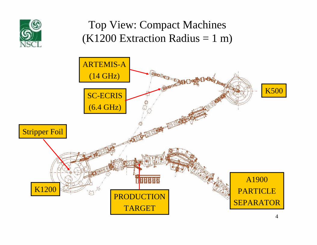
Top View: Compact Machines(K1200 Extraction Radius = 1 m)
ARTEMIS-A(14 GHz)
SC-ECRIS(6.4 GHz)
K500
K1200
Stripper Foil
PRODUCTIONTARGET
A1900PARTICLE
SEPARATOR

5
K500 Injected Beam Requirements:
2) K1200 Stripper ECRIS M/Q ~ 6
3) Production Target Shielding Limit ~ 4kWK500 Output < 10 euA
K500 Injection Beam < 30-40 euA
1) Small-sized cyclotron tight emittancerequirement [calculated to be 75 pi*mm*mr]
4) First Orbit Radius 20-27 kV extraction potential
5) 22 different “beam list” isotopesrapid and repeatable tunes required

6
From PAC07 (talk MXOXKI03)
“The key to high intensity and lowbeam losses is very careful control of
injection and extraction.”
Stuart Henderson, ORNL

7
Hardware Changes Affecting Beam Dynamics2003-2007 (Injection line In Orange)
May 2003: Revised ARTEMIS-A ExtractionRegionJuly 2004: Problem with ARTEMIS-A Hex field05-Sept-04: Install Small Bore Triplet (SBT) onSC-ECR17-Nov-04: Install S006SX, Remove Aperture 17-Dec-04: Repair K12 injection & K12C3,4Jan-05: ARTEMIS-A Permanent MagnetSextupole Bars ReplacedJan-05: SBT on SCECR moved up 5"Jan-05: Buncher moved up 12"Jan-05: K8C4 Beam Scraper (0.42") Installed16-Feb-05: remove S007AP10-Dec-05: Double Solenoid under K500; Bunchermoved down 4"10-Jan-06 Large Bore Triplet (LBT) installed onARTEMIS-A10-Jan-06: Moved Plasma Electrode and Puller onARTEMIS-A
10-Jan-06: remove R007Aperture10-Jan-06: Installed 0.3" Vt Collimation at Full Radiuson K500 K5MPSC7-Apr-06: Add K500 Phase Slits7-Apr-06: Add J033 4-Jaw Slits7-Apr-06: K5MPSC Gap reduced to 0.25"11-May-06: Reverse J046SN Polarity12-Jun-06: Install Double Doublet System (DDS) onARTEMIS-A12-June-06: Replace Buncher grids with 1 cm diawashers12-Jun-06: Swap R013QA/14QB with J042SN15-Jan-07 Inflector Collimator 4.2 2 mm (failed,returned to 4.2 mm)15-Jan-07: K5MPSC Gap reduced to 0.19"15-Jan-07: Einzel Lens + LBT installed on SCECR;remove S006SX15-Jan-07: Water-cool K12E1D drive rod19-Jan-07: reversed polarity of J056SN

8
Max Recorded Beam Intensities 2002-2006
Peak Intensities 2002-06
0
50
100
150
200
250
300
350
400
450
2001 2002 2003 2004 2005 2006 2007
Year
Bea
mC
urr
ent
[pn
A] O-16
Ar-40
Ca-40
Ca-48
Kr-78
Xe-124
Ni-58
Gains Largely from Injection Line improvements

9
Injection Line (~16.5 m) to K500
Original Configuration(Solenoid)
Electrostatic Q-TripletSextupole
Doublet-Octupole-DoubletSpherical Bender
(2009?)
Solenoid Doublet
(K500)
EmittanceScanner
RF Chopper
Improved Dipole
4-Jaw Slits
(ECRIS)

10
~2000: Add Aperture Plates

11
Less = Better
Apertures[mm] Beam
AnalyzedBeam[eA]
K500Inflector
[eA]
K500Extracted
[eA]
none 16O+3 400 159 1.1
7, 12, 25 16O+3 36 5 1.1
(from 2003)

12
Viewer Plates:Aluminum Coated with Phosphor (KBr or BaF2)

13
Viewer Plate Locations
J035VP(VP1)
J041VP(VP2)
J053VP(VP3)
The number part of the device name refers to its relative location.
(Side View)

14
The Following Movies Are Rated:

15
Rings of 58Ni Charge States (Vary R009 Dipole)(ECRISSolenoidDipoleSolenoidViewer)

16
Beam Transport for 48Ca8+
SSOL
-2.958
S91D
1.323
EXTR
STS1
APR1
SFC1
APR2
STS2
APR3
SFC2
SSOL
-2.958
S91D
1.323
EXTR
STS1
APR1
SFC1
APR2
STS2
APR3
SFC2
4He2+
ECR AnalysisMagnet
Solenoid FaradayCup
(from 2004)

17
With Electrostatic Triplet
EQA
-0.800
EQB
0.700
EQC
-0.800
S91D
1.323
1EQA
0.000
1EQB
0.000
J5M1
0.246
EXTR
STS1
APR1
SFC1
APR2
STS2
APR3
SFC2
All Ions Remain Together until Magnetic Bend
AnalysisMagnet
Triplet
(from 2004)

Short FocusingBeam Line is tuned to transmit a Q/A 1/6 Beam
ECR Beams often have Q/A > 1/6 Ionsof significant intensity (support gas)
Q/A > 1/6 ions are tightly focused
before reaching the analysis magnet
Beam at “short foci” creates high space-chargeforces driving desired beam ions radially outwards
(from 2004)

19
Definitive Solenoid Test Artemis B - 2007
Space-Charge Blow-Up from Solenoid Focusing
G. Machicoane (ICIS07)

20
Maximize the Good at the Expense of the Bad50mm Triplet vs. Solenoid Case
0
10
20
30
40
50
60
70
80
90
100
0 50 100 150 200 250 300
Beam emittance (Pi-mm-mrad)
Par
ticle
perc
ent(
%)
input
solenoid
ESQTS
Region of Interest Not Useable BeamSo Get Rid of It Early
(which is not easy to do)

21
Gains From better Tranmission
Analyzed source beam output (in pnA) and theresulting beam intensity extracted from the K1200. The
net efficiency normalized to source output hasincreased by about a factor of four from 2003 to 2006.

22
Problems Remain
Now: Overall beam intensities often limited to about 800Wby losses in the cyclotrons at beam extraction. (Deflectors!)
Future: How to beneficially use high intensity from SUSI?

23
Ideal Case for Perfect Injection
UncorrelatedRound Beam
(Object)
UncorrelatedRound Beam
(Image)
“Round”Beam
Lens 1 Lens 2

24
Our Less-than-Ideal Situation
Lens 1 Lens 2What kindof Object
givesStrange
Stuff as anImage?
StrangeStuff
?

25
Close Round Aperture: 25, 17, 12, 7 mm(ECRISTripletDipoleQuad DoubletViewer)
Round Cut give Triangular Beam!

26
“Star” Features more Evident w/oSolenoid Space Charge Issues
(from 2004)
16O+3 (using Electrostatic Triplet)

27
Highly Structured Object
X-Ray Image of Ionization Within the ECRIS
S. Biri, et. al.(from 2004)

28
VT2 view after first Beam LineSolenoid (GSI, 2006)

29
ECRIS Beam has a Special “Tag”
“Rings” morphinto “Stars” by
varying thefocusing strength
of lenses.
(Simulations:This is not explainedby 2nd Order Alone)

30
Ring to Star @ NSCL using Beam Line Solenoid(ECRISDouble DoubletDipoleSolenoidViewer)

31
Image Propagation thru Injection Line
Round Aperture

32
Hz Slit Scan J033XGap = 2 mm
“Should” show a narrow vertical line

33
Vz Slit Scan J033YGap = 4 mm
“Should” show a narrow horizontal line

34
Cut 90% of Intensity with J033 Slitscentered on Beam
(Slit half-way thru Injection Line, Viewer Just Before K500)
Slits are cutting only Intensity, NOT overall Emittance

35
ECRIS Beam Characteristics
1) Transverse Structure2) Large 2nd Order Aberrations (Triangle)3) Strong Phase space cross-coupling (beam is
correlated)4) Focusing morphs Triangle into Star5) Under some conditions, a fractal nature
(round cut can redevelop into a triangle-star)

36
The Question:
Can the extracted beam be dealt with in a way thatgives good 2D emittance without large correlations
but with reasonable intensities?
The Surprising Answer: Yes!

37
A Test a of 2nd Order Correction Scheme
At NSCL (August 2007)New Analysis Dipole
New, Stronger SextupoleDouble-Doublet moved for 2 wks to
ARTEMIS-B
In Principle, a Pi Phase advance between the sourcesextupole and an external sextupole should allowa full correction of the 2nd order aberrations.

38
A Most Useful Device(Poor Man’s 4D Emittance Scanner)
25mm
1.5 mm dia. HolesSpaced 4 mm apart

39
Layout for August 07 ARTEMIS-B Test
This drift allows the beam correlationsto be seen directly on the Viewer!
53 cm 37 cm79 cm 64 cm
EmittanceScanner
Viewer &Faraday Cup
SolenoidViewer
Grid &Faraday Cup
Sextupole
Electrostatic Quad Doublet x 2
Artemis-B

40
Initial Explorations
1) Tune Optics for Maximum Intensity on Faraday Cup.2) Remove Cup, Observe beam on Viewer 79 cm Downstream3) Take Photo4) Insert Grid (1 mm diameter holes, 4 mm apart)5) Take Photo

41
More!
WithoutGrid
WithGrid

42
Interesting …
ExpandedView

43
Then Pi-Phase Advance Optics …(Sextupole Off)
“Organized” Core!
44
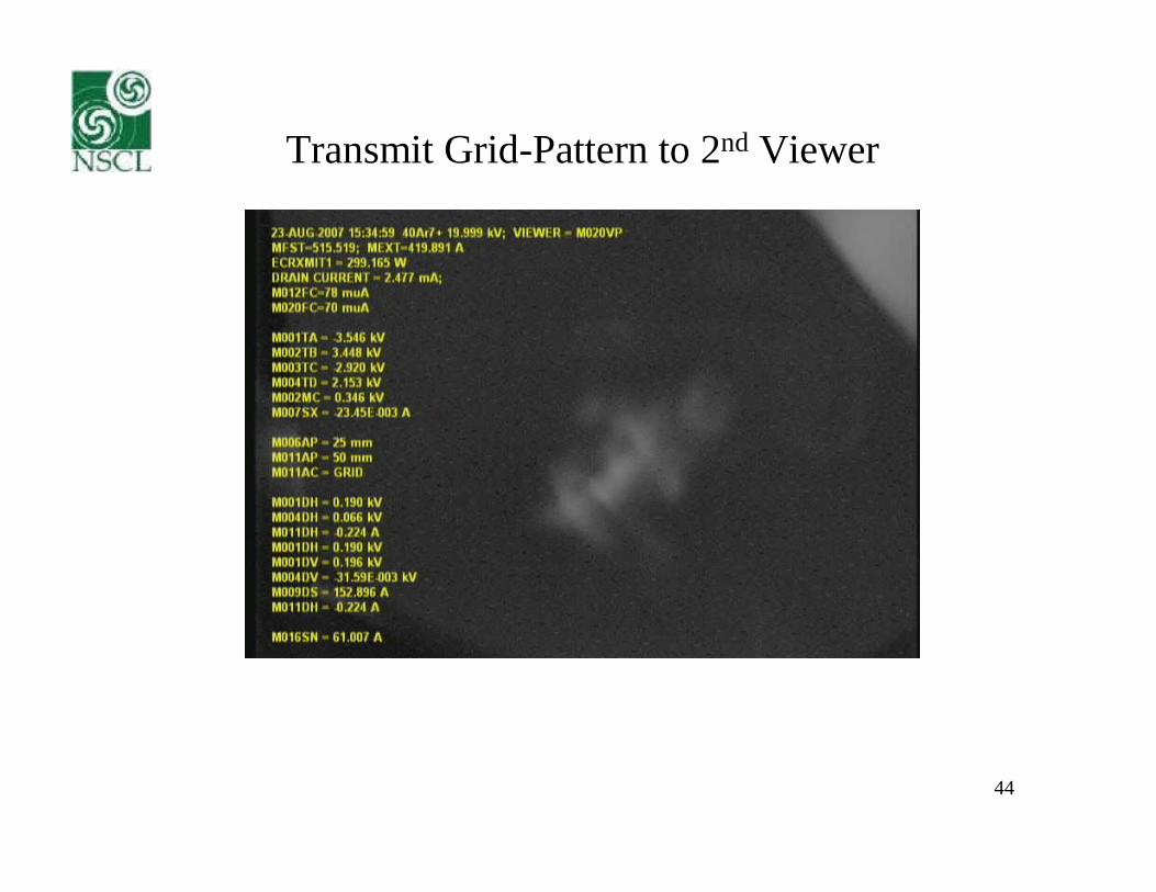
Transmit Grid-Pattern to 2nd Viewer
45
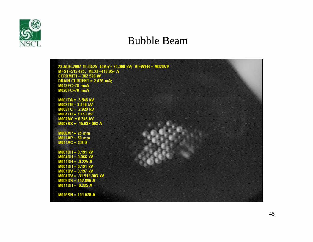
Bubble Beam

46
Try the Sextupole (1st Viewer)

47
Try the Sextupole (2nd Viewer)
The External Sextupole “brings in” highlyaberrated beam, but doesn’t affect the “core”at all(!)

48
A Test of 2nd Order Correction Scheme
Results not as anticipated,(Possibly due to 3rd order effects from the quads.)
However:There seems to be a relatively intense
part of the beam that is essentiallyUncorrelated(!)

49
Lucky Break?
The “Why” is not known,But
Can this “core” effect be used?

50
(Ultra) Low Emittance Tune for Inj. LineArtemis-A
51
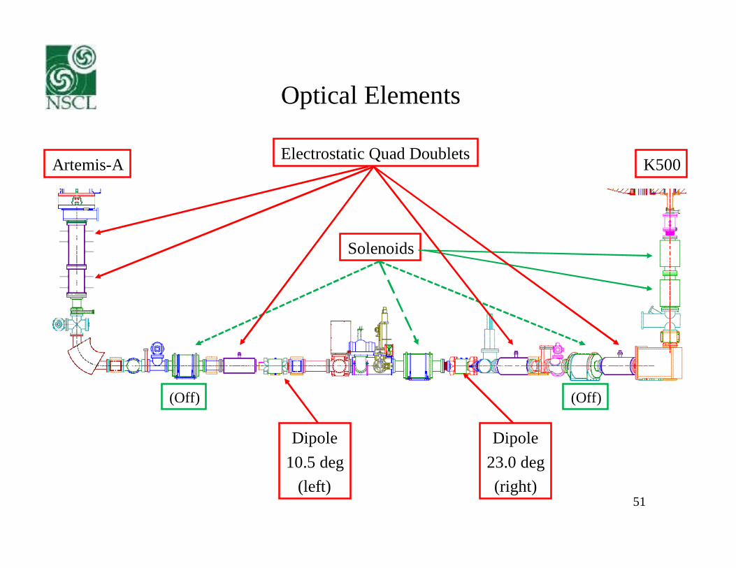
Optical Elements
Electrostatic Quad Doublets
Solenoids
Dipole10.5 deg
(left)
Dipole23.0 deg(right)
(Off) (Off)
Artemis-A K500

52
Magic Electrostatic Lens System:(can give a 90 Deg Phase Advance from
ECRIS Sextupole to an External Sextupole)
Quadrupole Doublet
Octupole
Quadrupole Doublet
Hz and Vt Steeringbuilt into first andlast lens elements
National Electrostatics Corporation calls it: The “Odd Duck”

53
Devices
SlitsJ033
AttenuatorGrid (1/3)
J034
EmittanceScanner
J035
ApertureR006AP
50/15 mm
ApertureR012AP
50/25/12 mm
ViewerJ035
ViewerJ041
ViewerJ053
Artemis-A K500

54
Analysis Magnet + Apertures
ApertureR006AP
50/15 mm ApertureR012AP
50/25/12 mm
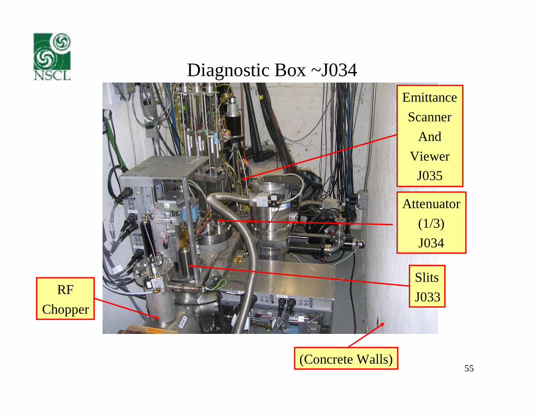
55
Diagnostic Box ~J034
SlitsJ033
Attenuator(1/3)J034
EmittanceScanner
AndViewer
J035
(Concrete Walls)
RFChopper

56
Beam Attenuator Plate (x 1/3)
~1 mm diameterHoles
~2.5mmCenter-to-center
15 cm

57
Step 1
(Off) (Off)
D-Doublet set to pi-phase advance or “focus”Through 15mm Aperture

58
Step 2
(Off) (Off)
Doublet set to give focus/waistAt J035VP
ViewerJ035
R006AP15 mm
R012AP12 mm

59
Step 3
J035 to J041 is an “almost” free drift of 2.1 m,meaning that the growth of the beam size
gives essentially the emittance angle information.
R006AP15 mm
R012AP12 mm
(Off) (Off)
ViewerJ041

60
Step 4
The grid pattern should be “organized” onJ035VP. It should remain so when focused by
J037SN solenoid onto J041.
R006AP15 mm
R012AP12 mm
(Off) ON

61
Step 5
It should be possible to close the J033 slits andsee the grid image on J041 cut smoothly and
sharply.
R006AP15 mm
R012AP12 mm
(Off) ON

62
Step 6
(Off) (Off)
If improvement is needed, search for the‘hot spot’ in front of R012 with steering
and small quadrupole changes,while keeping beam small on J035VP
ViewerJ035
R006AP15 mm
R012AP12 mm

63
Vary R001QA (Grid at R012)
R006AP50 mm
40Ar7+
R012AP25 mm
(Off)

64
Vary R004QA
40Ar7+
R006AP50 mm
R012AP25 mm
(Off)

65
Complication: Space Charge in Dipole?
58Ni11+
16O3+
= 1x1 cm
R006AP15/50 mm
R012AP12/50 mm

R006AP50 mm
R012AP12 mm
(Off)
66
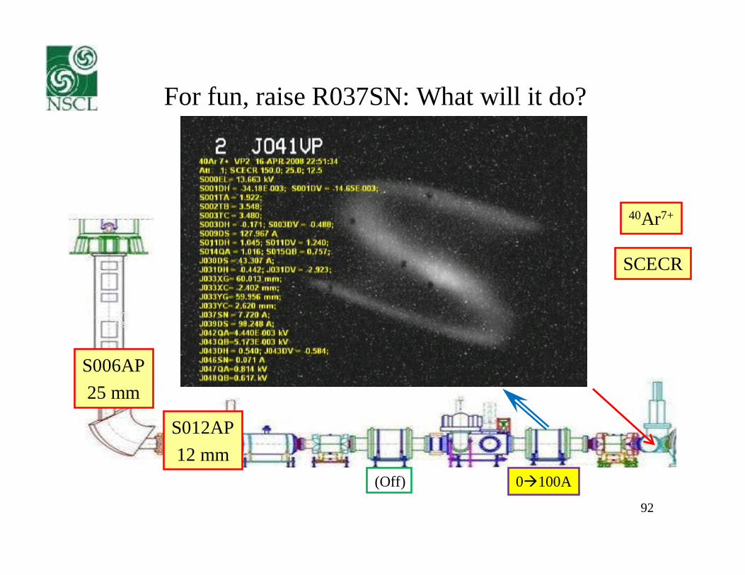
Vary R037SN: Big + Ring-to-Star Tagged(Bad!)
40Ar7+
80120A

67
(Initially) Better-Looking Tune:Open/Close R012AP
40Ar7+
R006AP50 mm
R012AP12/50 mm
(Off)

68
J033 Hz Slit Scan (Width = 4 mm)
40Ar7+
(Off)
R006AP50 mm
R012AP50 mm
(Off)
J0334x60mm

69
J035 Emittance Scan (Apertures Open)
J03360x60mm
R006AP50 mm
R012AP50 mm
(Off)

70
J035 Emittance Scan (R012AP = 12 mm)
J03360x60mm
R006AP50 mm
R012AP12 mm
(Off)

71
Cutting Effectiveness
J033Slits
cut mostlySize
Would likeSlits at J041
as anAngle Cutter
R012AP gives the most effectiveSingle Cut
R006AP50 mm
R012AP12 mm
(Off)

72
58Ni11+: Normal vs. Low Emittance Tune
R012 = 17.0 uA; J033 = 5.4 uA
R012 = 7.0 uA; J033 = 4.0 uA
x 2/3 x 1/3
Early Transmission LossTends to be offset by
Later Transmission Gains

73
58Ni11+: Emittance: High vs. Low
In the 2.1 m “almost”free drift between
the focus at J035VPand J041VP, the
difference in the twoemittances is directly
observable.
(16O3+)
74
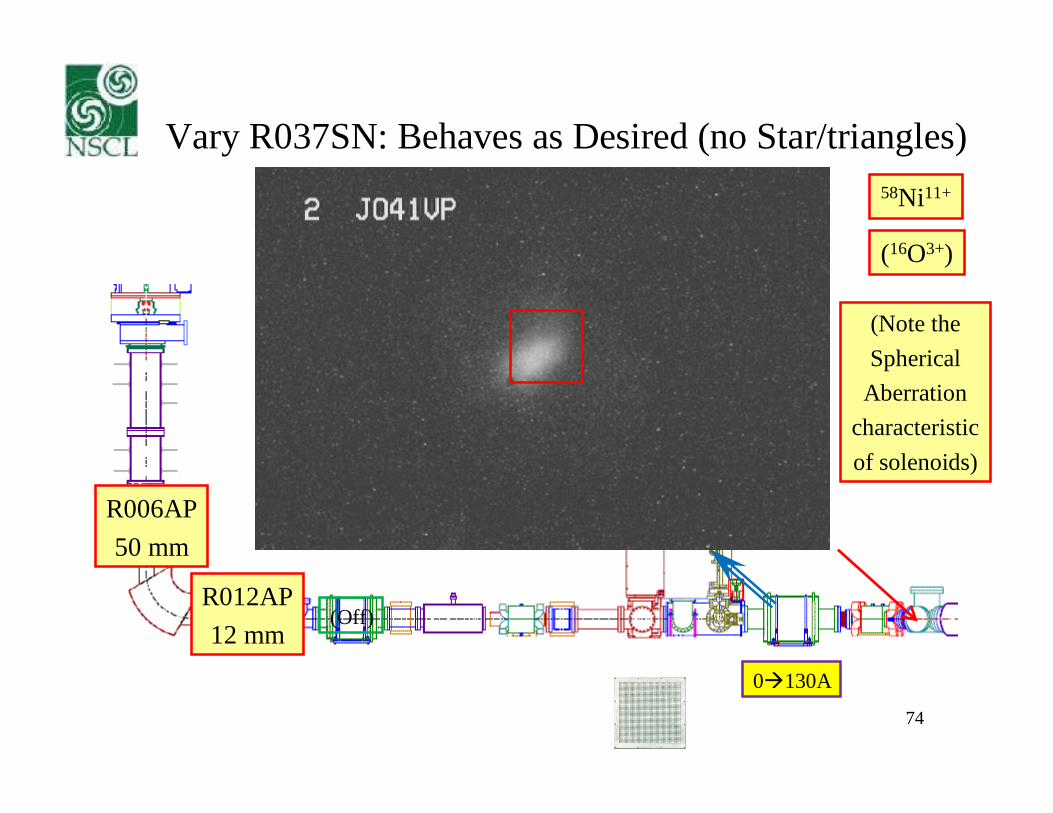
Vary R037SN: Behaves as Desired (no Star/triangles)58Ni11+
0130A
(16O3+)
(Note theSpherical
Aberrationcharacteristicof solenoids)
R006AP50 mm
R012AP12 mm
(Off)

75
What’s Being Cut by Apertures?
R006AP1550 mm
R012AP12 25 50 mm 130A
40Ar7+

76
What’s Being Imaged / Cut by Apertures?
40Ar7+
(Off)
R006AP50 mm
R012AP1250 mm
(Off)

77
Note!
This central piece of beam isnot being significantly cut by apertures. There
seem to be 3 similar low-emittance pieces,but on different trajectories. The apertures cut
2 of the 3 (plus a “cloud”) away.

J033 Slit Cut Good
58Ni11+
(16O3+)
130A
R006AP50 mm
R012AP12 mm
(Off)

79
Side Benefit: Better Charge State Resolution (<1%)
78Kr11+ 14N2+
J033 Slits60 x 10mm
40Ar8+
(Resolving Power ~ Dispersion/Magnification)
(Off)

Aside: Yes, the Octupole Works
R006AP50 mm
124Xe20+
R012AP12 mm
(Off) (Off)

81
Emittance Scanner Resolution
Position Resolution is ~0.5 mmBeam Widths > 5 mm Good
~1 mm diameterHoles
~2.5mmCenter-to-center
1 mm step size

82
Emittance Scanner Resolution
For the same beam, divergencemust increase as the spot size
on the scanner is made smaller
(Off)

83
Emittance Scanner Resolution
Divergence resolution ~ 6.7 mr
10 mr
6*pi*mm*mr 4*pi*mm*mr 3*pi*mm*mr
When divergences < ~10 mr, as they are for many of these measurements,the calculated emittance values depend only on the beam width.

84
Summary (A) of Low Emittance Tune Tests
40Ar7+, 58Ni11+, 78Kr11+, and 124Xe20+ beamswere tested and gave very similar optical results.
A bright beam core exists that has minimal, if any,cross-correlations.
2D rms emittances are reduced by at least a factor of 3-5
This core has about 1/3 of the total beam intensity.
The initial focusing element (Double Doublet)settings scale very precisely between beams and
extraction HV settings.

85
Summary (B) of Low Emittance Tune Tests
Minimal correlations allows clean slit cuts.
Changing the plasma chamber electrode diameter from8mm to 10mm increased both overall and “low emittance”
output by 30-40%, without significantly degradingbeam quality.
In the first (and, to-date, only) test with the K500,both injection and extraction efficiency weresignificantly improved; only 50-60% of the
previous injected intensity was needed to achieve thesame K500 output current.

86
Brightness
Intensity On A Faraday CupThat Cannot Be
Injected, Accelerated, And ExtractedCleanly Is Useless (Or Worse)

87
Homework for the Theory Types
Given the complicated nature of the beam structurefrom an ECR ion source ….
… how is it even remotely possible to organize (de-correlate)this beam using linear, first order, optical focusing elements?
It’s not!
So it already exists (focusing and steering merely select),But Why?

88
?
Can the “core” be separated in systemsUsing solenoid or other focusing?
Can the “core” be separated by“processing”
after the analysis magnet only?

89
An NSCL World Record?
Operating ECR Ion Sources = 4
Ion Source Group Members = 3
Sources per Sorcerer = 1.333
One Very Over-Worked Group

90
So, In Particular
Thanks for letting me play withYour Toys!

91
The Cast (Lord(s) of the Rings IV)
BEAM PHYSICS•Felix Marti•Marc Doleans•Xiaoyu Wu•Q. Zhao
ION SOURCE•Peter Zavodszky•G. Machicoane•Dallas Cole•Larry Tobos
GSI•Peter Spaedtke
92
For fun, raise R037SN: What will it do?
S006AP25 mm
40Ar7+
S012AP12 mm
(Off) 0100A
SCECR

93
---


![Accelerators at TRIUMF · 2018. 12. 12. · Electron Cyclotron Resonance ion source (ECRIS) charge state breeder Microwave Injection Hexapole (Radial Magnetic Field) Beam f B = 28B[T]](https://static.fdocuments.net/doc/165x107/60ffd63fdac22d55445c4e02/accelerators-at-triumf-2018-12-12-electron-cyclotron-resonance-ion-source-ecris.jpg)