A Menu-based Universal Control Protocol18716/FULLTEXT01.pdf · Department of Science and Technology...
75
Department of Science and Technology Institutionen för teknik och naturvetenskap Linköpings Universitet Linköpings Universitet SE-601 74 Norrköping, Sweden 601 74 Norrköping Examensarbete LITH-ITN-MT-EX--02/34--SE A Menu-based Universal Control Protocol Per-Ola Gustafsson Marcus Ohlsson 2002-05-30
Transcript of A Menu-based Universal Control Protocol18716/FULLTEXT01.pdf · Department of Science and Technology...
Department of Science and Technology Institutionen för teknik och naturvetenskap Linköpings Universitet Linköpings Universitet SE-601 74 Norrköping, Sweden 601 74 Norrköping
Examensarbete LITH-ITN-MT-EX--02/34--SE
A Menu-based Universal Control Protocol
Per-Ola Gustafsson Marcus Ohlsson
2002-05-30
LITH-ITN-MT-EX--02/34--SE
A Menu-based Universal Control Protocol
Examensarbete utfört i Medieteknik vid Linköpings Tekniska Högskola, Campus Norrköping
Per-Ola Gustafsson Marcus Ohlsson
Handledare: Björn Gudmundsson och Anders Nilsson Examinator: Björn Gudmundsson
Norrköping den 30/5 2002
Rapporttyp Report category Licentiatavhandling x Examensarbete C-uppsats X D-uppsats Övrig rapport ________________
Språk Language Svenska/Swedish x Engelska/English ________________
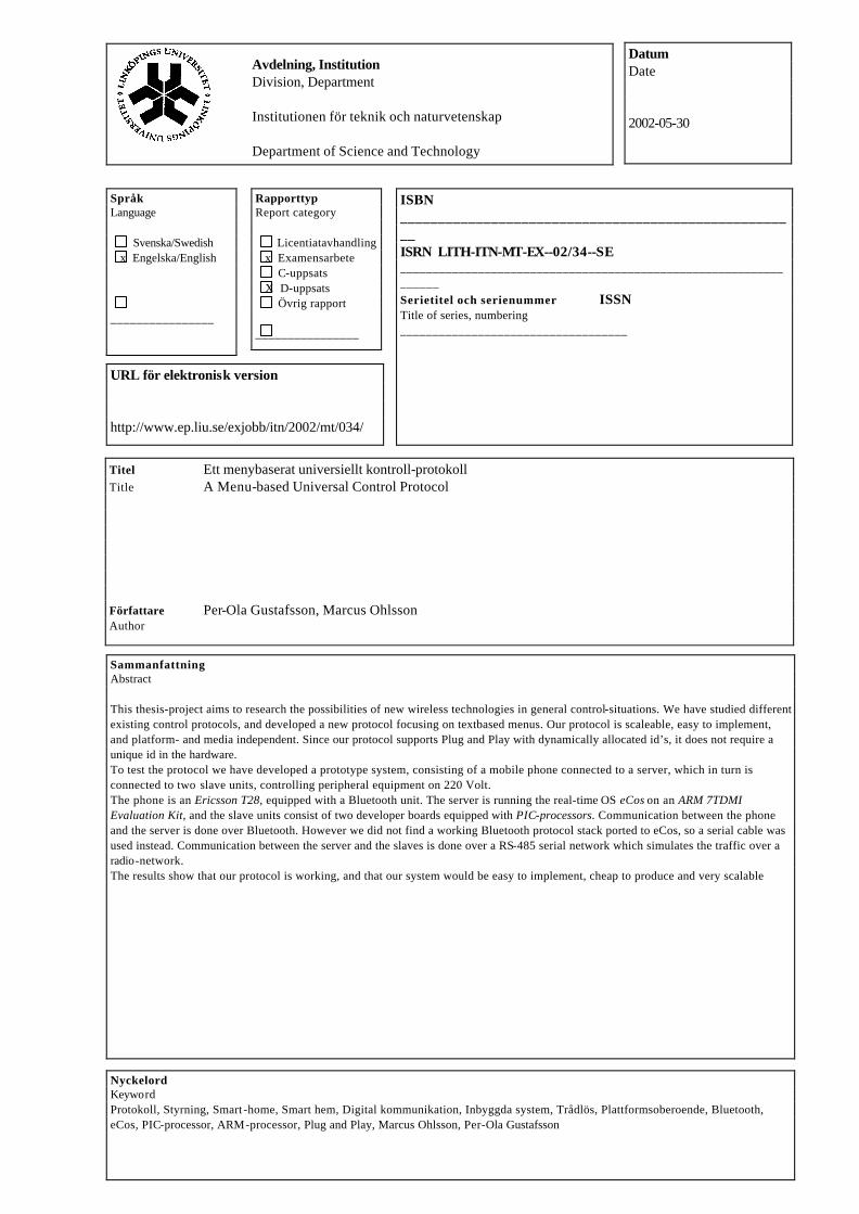
Titel Ett menybaserat universiellt kontroll-protokoll Title A Menu-based Universal Control Protocol Författare Per-Ola Gustafsson, Marcus Ohlsson Author
Sammanfattning Abstract This thesis-project aims to research the possibilities of new wireless technologies in general control-situations. We have studied different existing control protocols, and developed a new protocol focusing on textbased menus. Our protocol is scaleable, easy to implement, and platform- and media independent. Since our protocol supports Plug and Play with dynamically allocated id’s, it does not require a unique id in the hardware. To test the protocol we have developed a prototype system, consisting of a mobile phone connected to a server, which in turn is connected to two slave units, controlling peripheral equipment on 220 Volt. The phone is an Ericsson T28, equipped with a Bluetooth unit. The server is running the real-time OS eCos on an ARM 7TDMI Evaluation Kit, and the slave units consist of two developer boards equipped with PIC-processors. Communication between the phone and the server is done over Bluetooth. However we did not find a working Bluetooth protocol stack ported to eCos, so a serial cable was used instead. Communication between the server and the slaves is done over a RS-485 serial network which simulates the traffic over a radio-network. The results show that our protocol is working, and that our system would be easy to implement, cheap to produce and very scalable
ISBN _____________________________________________________ ISRN LITH-ITN-MT-EX--02/34--SE _________________________________________________________________ Serietitel och serienummer ISSN Title of series, numbering ___________________________________
Nyckelord Keyword Protokoll, Styrning, Smart -home, Smart hem, Digital kommunikation, Inbyggda system, Trådlös, Plattformsoberoende, Bluetooth, eCos, PIC-processor, ARM-processor, Plug and Play, Marcus Ohlsson, Per-Ola Gustafsson
Datum Date 2002-05-30
URL för elektronisk version http://www.ep.liu.se/exjobb/itn/2002/mt/034/
Avdelning, Institution Division, Department Institutionen för teknik och naturvetenskap Department of Science and Technology
A Menu-based Universal Control Protocol
Masters thesis
By Per-Ola Gustafsson and Marcus Ohlsson
October 2001 to March 2002
This thesis project was done on at Teleca Exallon Systems AB, in Malmö between October 2001 and March 2002 as a collaboration between Per-Ola Gustafsson as a Master’s thesis in Electronic Engineering at Lund University and Marcus Ohlsson as a Master’s thesis in Media Technology at Linköping University. Supervisors: Anders Nilsson Department of Computer Science, Lund University Björn Gudmundsson ITN, Linköping University
Abstract This thesis-project aims to research the possibilities of new wireless technologies in general control-situations. We have studied different existing control protocols, and developed a new protocol focusing on textbased menus. Our protocol is scaleable, easy to implement, and platform- and media independent. Since our protocol supports Plug and Play with dynamically allocated id’s, it does not require a unique id in the hardware. To test the protocol we have developed a prototype system, consisting of a mobile phone connected to a server, which in turn is connected to two slave units, controlling peripheral equipment on 220 Volt. The phone is an Ericsson T28, equipped with a Bluetooth unit. The server is running the real-time OS eCos on an ARM 7TDMI Evaluation Kit, and the slave units consist of two developer boards equipped with PIC-processors. Communication between the phone and the server is done over Bluetooth. However we did not find a working Bluetooth protocol stack ported to eCos, so a serial cable was used instead. Communication between the server and the slaves is done over a RS-485 serial network which simulates the traffic over a radio-network. The results show that our protocol is working, and that our system would be easy to implement, cheap to produce and very scalable.
1
Index 1 Preface ___________________________________________________________ 4
2 Introduction _______________________________________________________ 5
3 Overview of existing interesting techniques ______________________________ 7
3.1 X10 ________________________________________________________________8 3.1.1 The Protocol _____________________________________________________________ 8 3.1.2 X10 from our point of view _________________________________________________ 9
3.2 JINI _______________________________________________________________10 3.2.1 The JINI technology ______________________________________________________ 10 3.2.2 The JINI-Protocol ________________________________________________________ 11 3.2.3 JINI from our point of view ________________________________________________ 12
3.3 S.N.A.P – Scaleable Node Address Protocol ______________________________13 3.3.1 The Protocol ____________________________________________________________ 13 3.3.2 S.N.A.P from our point of view _____________________________________________ 14
3.4 HAVi ______________________________________________________________15
3.5 LonTalk ___________________________________________________________15
3.6 Other Protocols, Standards and projects ________________________________16
4 Hardware and platforms ____________________________________________ 17
4.1 The Server _________________________________________________________18 4.1.1 Serial ports _____________________________________________________________ 19 4.1.2 Ethernet controller _______________________________________________________ 19
4.2 eCos_______________________________________________________________20 4.2.1 General about eCos_______________________________________________________ 21 4.2.2 Configuring eCos ________________________________________________________ 21
4.3 The Slave units______________________________________________________22
4.4 Ericsson Mobile phone and AT-commands ______________________________23
4.5 Bluetooth __________________________________________________________25 4.5.1 OpenBT _______________________________________________________________ 25 4.5.2 HelloBT _______________________________________________________________ 26 4.5.3 WOSP (Wireless Open Source Platform) ______________________________________ 26 4.5.4 Serial cable solution ______________________________________________________ 26
4.6 Radio RF network solution____________________________________________27
4.7 RS485 radio network simulator ________________________________________28
5 Software design ___________________________________________________ 29
5.1 Hardware Abstraction Layer __________________________________________31
5.2 GUI _______________________________________________________________32 5.2.1 The GUI’s parent-system __________________________________________________ 33 5.2.2 Ping user _______________________________________________________________ 33
5.3 At-port ____________________________________________________________33
5.4 Database ___________________________________________________________34 5.4.1 Memory-structure of the database ___________________________________________ 35
2
5.5 Remote Device Server (RD Server) _____________________________________36 5.5.1 Virtual units ____________________________________________________________ 36 5.5.2 Detecting new units ______________________________________________________ 37 5.5.3 Removing Devices _______________________________________________________ 37 5.5.4 Refreshing the menus _____________________________________________________ 37 5.5.5 Execute commands on the devices ___________________________________________ 37
5.6 The Menu System ___________________________________________________38
5.7 SArray ____________________________________________________________40
5.8 Mailbox System _____________________________________________________41 5.8.1 Mailbox Structures _______________________________________________________ 41 5.8.2 Mailbox data structures____________________________________________________ 42
5.9 The Protocol________________________________________________________43 5.9.1 General protocol issues____________________________________________________ 43 5.9.2 Identification of slave units_________________________________________________ 43 5.9.3 Net number- and id-commands______________________________________________ 44 5.9.4 Menu- and name-collecting commands _______________________________________ 44 5.9.5 Action commands ________________________________________________________ 44 5.9.6 Ping-commands _________________________________________________________ 45
5.10 Design of the slave units ______________________________________________46 5.10.1 General design issues due to choice of platform ______________________________ 46 5.10.2 The Application layer___________________________________________________ 47 5.10.3 The Hardware layer ____________________________________________________ 47 5.10.4 Weak points __________________________________________________________ 47
6 Result ___________________________________________________________ 48
6.1 The test ____________________________________________________________48
7 Discussion _______________________________________________________ 49
7.1 Expandability and Usefulness _________________________________________50
Appendix A - Setting up the environment___________________________________ 51
A.1 Introduction to the development environment ____________________________51
A.2 Cygwin ____________________________________________________________53
A.3 Cross compiling the compiler for ARM _________________________________ 53 A.3.1 Downloading necessary files _______________________________________________ 53 A.3.2 Preparations ____________________________________________________________ 54 A.3.3 Building the tools ________________________________________________________ 55
A.4 CVS_______________________________________________________________56
A.5 eCos Configuration Tool______________________________________________57
A.6 Building the application and loading it to the board _______________________58
Appendix B - X10 specification ___________________________________________ 59
Appendix C - Details on the RS485 network_______________________________ 60
Appendix D - Menubased Universal Control Protocol_________________________ 61
D.1 Main message framework_____________________________________________61
D.2 Message framework for the different messages ___________________________62
3
D.2.1 Clear System IDs [CSI][0x80][CMD] ________________________________________ 62 D.2.2 Reset System [RES][0x81][CMD] ___________________________________________ 62 D.2.3 Clear Unit ID [CUI][0x82][CMD] ___________________________________________ 63 D.2.4 Identify New Units [INU][0x83][CMD] ______________________________________ 63 D.2.5 I Am Blank [IAB][0x84][REPLY] ___________________________________________ 64 D.2.6 Set Id and Net [SIN][0x85][CMD]___________________________________________ 64 D.2.7 Get Unit Description [GUD][0x86][CMD] ____________________________________ 65 D.2.8 Unit Description Reply [UDR][0x87][REPLY] _________________________________ 65 D.2.9 Get Menu/Action [GMA][0x88][CMD] _______________________________________ 66 D.2.10 Menu/Action Reply [MAR][0x89][REPLY] _________________________________ 66 D.2.11 Run Device Action [RDA][0x8A][CMD] ___________________________________ 67 D.2.12 Device Action Reply [DAR][0x8D][REPLY] ________________________________ 67 D.2.13 Ping Unit [PUN][0x8B][CMD] ___________________________________________ 68 D.2.14 Ping Unit Reply [PUR][0x8C][REPLY] ____________________________________ 68
Appendix E - References ________________________________________________ 69
4
1 Preface This project took place at Teleca Exallon Systems AB, in Malmö. The thesis work was done during 8 months (October 2001 to May 2002) and is a collaboration between two students, educations and universities. Per-Ola Gustafsson as a Master’s thesis in Electronic Engineering at Lund University Marcus Ohlsson as a Master’s thesis in Media Technology at Linköping University. The different backgrounds and interests of the two of us have complimented each other. Per-Ola has focused on the hardware, while Marcus has focused on the server application. The project involved the development of a cross-platform prototype system for testing our protocol. This system was built from scratch on three different hardware- and OS-platforms, and we had to solve many different problems ranging from low-level electronics problems all the way to high-level system design questions. This gave us a broad knowledge in many areas such as real-time operating systems, hardware structure, protocol design, software design and user interface. During the project we ran into many interesting problems which delayed the project, and we had to cut down the development of the prototype some. The people at Teleca Exallon Systems have been very helpful, and assisted us with lot of information that would have been hard to find elsewhere. We would like to thank everyone who helped us make this project a success. First we would like to thank our supervisor Anders Nilsson, at the Department of Computer Science, Lund University for guidance, and our supervisor Björn Gudmundsson at ITN, Linköping University for helping us with the report. We would also like to thank Anders Ohlsson at Teleca for letting us be guided by our inspiration, and supporting us with hardware. We are grateful to the people at Teleca, and would like to thank Gustav Engdahl, Anders Hansson, Andreas Mortin, Fredrik Pålsson, Patrik Ryd and Roger Stoltz for helping us with the project. We would also specially like to thank Arne Ohlsson who has motivated and supported us throughout the whole project. And finally we would like to thank the Bangkok Thai Restaurant for giving us inspiration, and fortifying us every day.
5
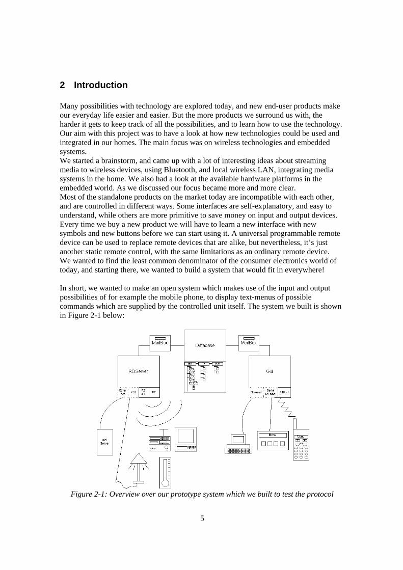
2 Introduction Many possibilities with technology are explored today, and new end-user products make our everyday life easier and easier. But the more products we surround us with, the harder it gets to keep track of all the possibilities, and to learn how to use the technology. Our aim with this project was to have a look at how new technologies could be used and integrated in our homes. The main focus was on wireless technologies and embedded systems. We started a brainstorm, and came up with a lot of interesting ideas about streaming media to wireless devices, using Bluetooth, and local wireless LAN, integrating media systems in the home. We also had a look at the available hardware platforms in the embedded world. As we discussed our focus became more and more clear. Most of the standalone products on the market today are incompatible with each other, and are controlled in different ways. Some interfaces are self-explanatory, and easy to understand, while others are more primitive to save money on input and output devices. Every time we buy a new product we will have to learn a new interface with new symbols and new buttons before we can start using it. A universal programmable remote device can be used to replace remote devices that are alike, but nevertheless, it’s just another static remote control, with the same limitations as an ordinary remote device. We wanted to find the least common denominator of the consumer electronics world of today, and starting there, we wanted to build a system that would fit in everywhere! In short, we wanted to make an open system which makes use of the input and output possibilities of for example the mobile phone, to display text-menus of possible commands which are supplied by the controlled unit itself. The system we built is shown in Figure 2-1 below:
Figure 2-1: Overview over our prototype system which we built to test the protocol
6
The least common denominator of consumer electronic is a textbased output, scrolling buttons, and a yes/no input. This is the most basic form of a control-device. You have it in TV, VCR, telephones, some stereos and most important of all, you have it in the mobile phones! Different brands, and different ways to present information, but it is always possible to display a menu, choose an item and to press yes or no. We also wanted to take advantage of the coming Bluetooth enabled mobile phones, which could serve as the perfect universal remote control unit. Further discussions lead us to the following criteria of the system: • Cheap and easy to implement
Since the protocol is intended for use in a household we have to make it cheap. • Scalable to fit more complex controller-situations
For example to control a computer, a Home Media platform or a complex alarm system.
• Controllable by any Menu based unit To avoid being stuck with a special remote-device, we wanted to make it possible to make use of existing control-devices. For example the graphical interface of a television set and a remote control, or even a simple textbased menu system of a Bluetooth enabled mobile phone.
• Plug and Play-enabled The user should not have to install anything or change the remote control, or even learn the new product. Just put it where you want it, and start controlling it with your standard control-unit.
• Optional Security For sensitive information like alarms and such, we need support for encrypted information.
• Wireless support Bluetooth1 or RF (Radio Frequency).
• Power efficient Comes from the need of wireless units.
• Open and platform independent Since we do not know what systems the home of the future will host, we have to make it as open as possible.
7
3 Overview of existing interesting techniques We have looked at different new technologies that could be used in our system. We have considered Bluetooth1, RF (Radio Frequency), IEEE-1394 (FireWire)2, Infra red, “WaveLAN” IEEE-802.11b and HomeRF3. We decided to use Bluetooth between the mobile phone and the server, because it is available in many new mobile phones, and it is also power efficient. Between the server and the slave units we choose to use RF, because it is power efficient, and the transceivers are cheap, in contradiction to the Bluetooth transceivers. We have also looked at several different protocols4 for different purposes. We have compared them, and been inspired by some of them. In this chapter we will introduce some of the more interesting protocols, which relate to our own protocol. Most of the protocols are bound to physical layers, which may not always be suitable. For example the X105, and CEBus-systems13 are dependent upon the powerline, which is not reliable in today’s European houses, because of disturbances from other communicating systems and digital products, such as computers, dishing machines, and vacuum cleaners. Our aim is to make our protocol open, so it can be used on many different physical layers. Some of the existing protocols can be used to transport media data, like streaming audio and video. Since this will need special hardware, because of the high bandwidth demands, we have chosen to focus only on controlling. It would also create compatibility issues if we were to include support for audio or video-streams.
8
3.1 X10
X105 is a pure home automation protocol developed in the late 70’s by the Scottish company Pico Electronics. Their patent expired in 1997, and the X10 protocol is now an open standard. The protocol is limited, but simple, and uses the existing electrical cables to transmit signals between devices. X10 is mostly used in America on their 110V-system, but there are also devices for the 220V-system to a lesser extent. An X10 device is attached to the electrical net with an ordinary 110V-plug, and is assigned an id by input from the user by, for example, setting a switch to a certain housecode and numbercode. This means that two units can have the same id, and thus both of them will react on commands addressed to their id.
3.1.1 The Protocol One bit consists of three 120Mhz-bursts (one for each zerocrossing in the American 3-phase 60Hz North American wiring ). The bits are sent both true and complemented, and the code sequence is repeated without the Start Code, with a 3 cycle break in-between. The Start Code is the reserved code ”1110”. Meaning of the bytes: Start Code House Code ’A’ Number Code ’2’ Bytes to be sent 1 1 1 0 0 1 1 0 1 1 1 0 0 Actual sent bytes (two per cycle)
1 1 1 0 01 10 10 01 10 10 10 01 01
Table 3-1 Example of a X10 command sequence. After the Start Code is sent, the House Code is sent. This addresses the ”net”, or house. Next a Key Code is sent, which can be either a Number Code to address a device, or a Function Code to specify a command. The Key Codes are five bits that define 16 numbers (Number Codes), and 15 commands (Function Codes). Each sequence is sent twice, and a silent gap of 3 cycles between the sequences is required. Except for the ”Bright” and ”Dim”-commands, which are sent continually. In short: 3 burst/ bit -> each bit sent twice (except Start Code) -> Start Code + House Code + Number Code makes up a sequence -> each sequence sent two times, with 3 cycles of silence between (except ”Bright” and ”Dim”) -> one sequence-pair with numbercode and one pair with Function Code makes a complete address and command.
9
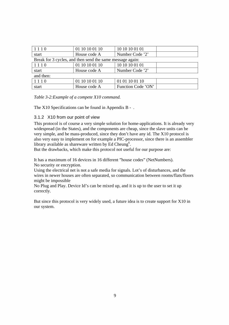
1 1 1 0 01 10 10 01 10 10 10 10 01 01 start House code A Number Code ’2’ Break for 3 cycles, and then send the same message again: 1 1 1 0 01 10 10 01 10 10 10 10 01 01 start House code A Number Code ’2’ and then: 1 1 1 0 01 10 10 01 10 01 01 10 01 10 start House code A Function Code ’ON’ Table 3-2:Example of a compete X10 command. The X10 Specifications can be found in Appendix B - .
3.1.2 X10 from our point of view This protocol is of course a very simple solution for home-applications. It is already very widespread (in the States), and the components are cheap, since the slave units can be very simple, and be mass-produced, since they don’t have any id. The X10 protocol is also very easy to implement on for example a PIC-processor, since there is an assembler library available as shareware written by Ed Cheung6. But the drawbacks, which make this protocol not useful for our purpose are: It has a maximum of 16 devices in 16 different ”house codes” (NetNumbers). No security or encryption. Using the electrical net is not a safe media for signals. Lot’s of disturbances, and the wires in newer houses are often separated, so communication between rooms/flats/floors might be impossible No Plug and Play. Device Id’s can be mixed up, and it is up to the user to set it up correctly. But since this protocol is very widely used, a future idea is to create support for X10 in our system.
10
3.2 JINI
JINI7 is an open network technology for assembling services (devices, databases and applications) and clients. Built on Java, its main focus is to create large, reliable networks out of unreliable parts where system administration is minimised. A device that wishes to connect to a JINI-network, must have the following two properties: A Java Virtual Machine (JVM), with access to needed packages. A properly configured network protocol stack. This means that JINI is a high-level protocol, which depends on Java. Though the network protocol can be of any sort, JINI’s main focus will be on IP, and on internet-based technology.
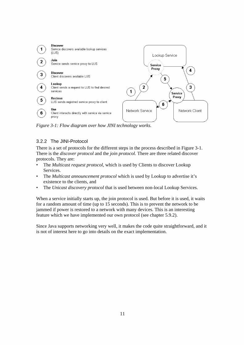
3.2.1 The JINI technology A JINI network has four basic objects: Network service: The service to be controlled. For example a video, an alarm, a light switch, or an air conditioner. A service can also act as a client, controlling another service. Network client: A control unit. For example a mobile phone, a remote control, or an automatic system, like an alarm or a computer. Lookup service: The server, which will keep track on the services available in the network, and also store their service proxies and distribute them to the clients. Service Proxy: The “glue” or “applet” between client and server, specifying the protocol. A piece of code, which is needed to control the service. Each service has its own proxy, and distributes it to the clients via the lookup service.
11
Figure 3-1: Flow diagram over how JINI technology works.
3.2.2 The JINI-Protocol There is a set of protocols for the different steps in the process described in Figure 3-1. There is the discover protocol and the join protocol. There are three related discover protocols. They are: • The Multicast request protocol, which is used by Clients to discover Lookup
Services. • The Multicast announcement protocol which is used by Lookup to advertise it’s
existence to the clients, and • The Unicast discovery protocol that is used between non-local Lookup Services. When a service initially starts up, the join protocol is used. But before it is used, it waits for a random amount of time (up to 15 seconds). This is to prevent the network to be jammed if power is restored to a network with many devices. This is an interesting feature which we have implemented our own protocol (see chapter 5.9.2). Since Java supports networking very well, it makes the code quite straightforward, and it is not of interest here to go into details on the exact implementation.
12
3.2.3 JINI from our point of view A device following the JINI-standard has the possibility to be remotely controlled, but also to act as master, and control other devices. Two nets can be linked together to form a bigger net, so that for example two homes would be able to interact, and control each other. These features are very good in big self-maintaining systems, but in our situation we just need to be able to control one way, so it is not interesting for our purpose. JINI’s two requirements on the devices are both in conflict with our aim; JINI requires Java, which means that it is not platform independent. It is not, as we suggest, an open, platform independent protocol, but rather a technique, which puts requirements on both hardware and software. JINI also requires a network protocol stack, preferably an IP-stack and a MAC ID, which brings up the costs when manufacturing slave-units. This means that JINI cannot be used, but nevertheless the structure of the system is much of what we need for our system, and it has inspired us when building our own protocol. Continuing the discussion in the introduction about finding the least common denominator, JINI has chosen Java as a least common denominator. Thus putting the restraint on consumer electronic to be equipped with Java1, to be able to interpret the “Service Proxy”. But since we have chosen to use text-based menus in our system, we want to use the general idea from JINI, but replacing the Java code in JINI’s “Service Proxy” with a text based menu. This will later be the core of our system. The summary is that we can make our protocol less complicated on the high level, and still use the same general structure and ideas that JINI has. The implementation of the JINI protocol is fairly straight forward, since it is all based on the IP-protocol and Java, but since our implementation cannot depend on either, it will be more complicated.
1 A slave-unit does not have to support Java itself, but it must be able to send a service proxy-code in Java to the master when requested.
13
3.3 S.N.A.P – Scaleable Node Address Protocol SNAP8 is a protocol developed in 1998-2002 by the Swedish company High Tech Horizon9. It is a flexible control-protocol for many different applications. Its main features are: • Easy to implement on any platform, and in any language. • Scaleable. • 8 different error-detecting methods (Checksum, FEC etc.). • Can be used in master/slave and/or peer-to-peer. • Media independent.
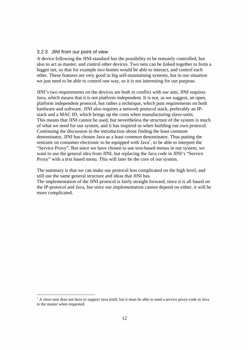
3.3.1 The Protocol First a synchronisation byte is sent, and after that, two header definition bytes follow. These define what the following bytes will mean, and which bytes should be sent or not. This makes it very scaleable, just as the name implies.
Figure 3-1: Overview of S.N.A.P protocol. Synchronisation byte: The first byte is the Synchronisation byte, which is set to 01010100 as default. The Header Definition Byte 1 (HDB1): Defines how many bytes will be used for Destination Address Byte (DAB), Source Address Byte (SAB) and Protocol specific Flag Bytes (PFB). The Header Definition Byte 2 (HDB2): Same function as HDB1, but defines the Number of Data Bytes (NDB) to be transmitted (0-512, with a “User specified”-option) and the Error Detection Method (EDM) which
14
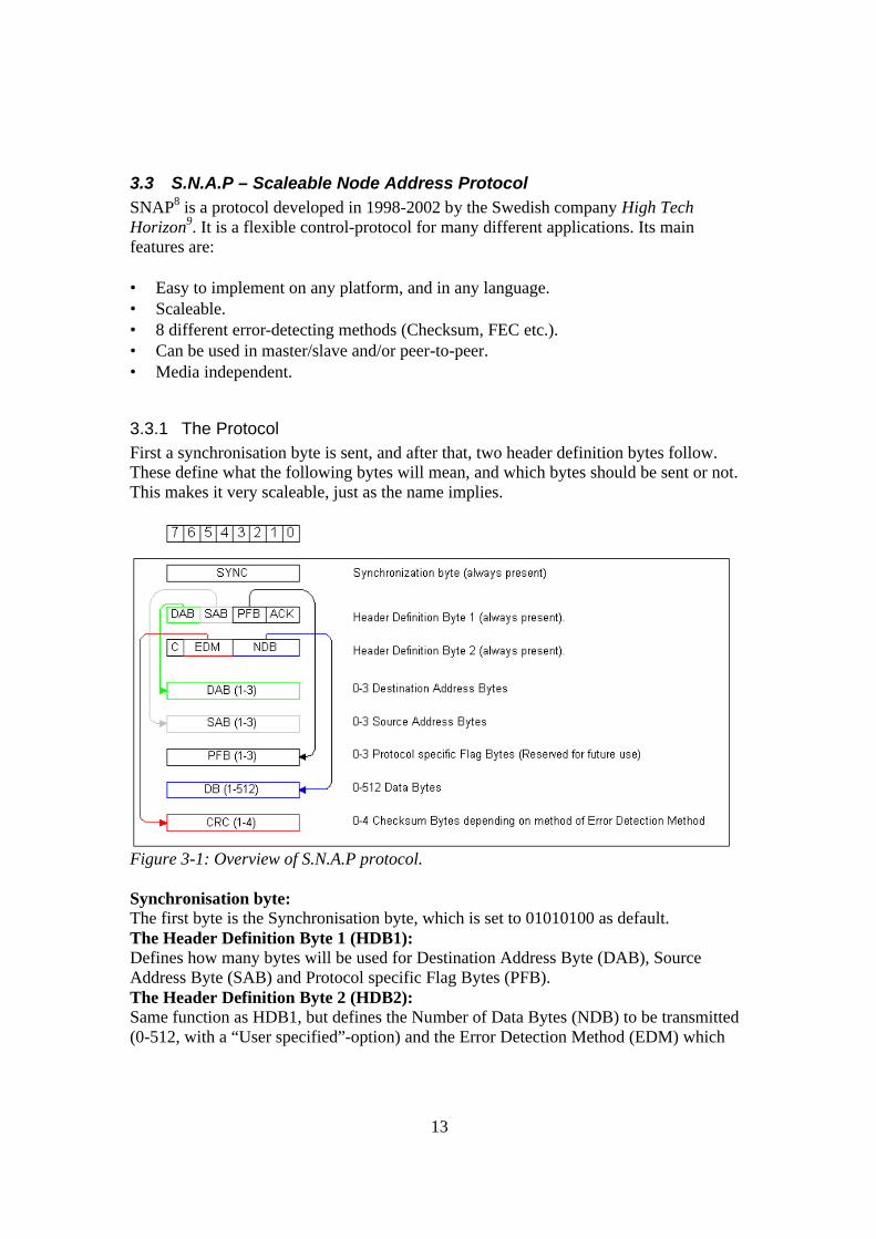
defines how many Checksum Bytes will be transmitted. HDB2 also contains the command mode bit, which indicates that DB1 contains a command instead of data. Destination Address Bytes (DAB): Depending on what is declared in the two DAB-bits in HDB1 this can be skipped, or be up to three bytes long. Skipping the address is a good way to save protocol overhead, when the network only has two nodes. Source Address Bytes (SAB): See DAB. Protocol specific Flag Bytes (PFB): These flags are reserved for future use. Examples of use are: Remote configuration, Packet counter, Priority and such. Data Bytes (DB): This is the data to be sent. The protocol supports datalengths of 0,1,2,3,4,5,6,7,8,16,32,64,128,256,512 and also supports the user to specify fixed length. First byte can be a command if the Command-bit in HDB2 is set. Checksum Bytes (CRC): The Checksum is computed depending on what is set in the EDM-bits in HDB2. The following Error Detection methods are supported: 3 times re-transmission, 8-bit checksum, 8-bit CRC, 16-bit CRC, 32-bit CRC FEC, and also supports user specified error detection.
Figure 3-2: S.N.A.P examples
3.3.2 S.N.A.P from our point of view Much of this satisfies our goals, but S.N.A.P is a lower layer protocol, which specifies the communication between the units. We also need a higher-level protocol with support for Plug and Play. Also our datastructure with the menus will be very specific, and well defined. What is most interesting is that S.N.A.P is very scaleable, and that the user-specified possibilities make the protocol usable for a wide range of purposes. S.N.A.P’s support for different media, and different encryption is a good point, but the tricky part is to implement it in the devices, and for our specific purpose this scalability will just add unnecessary overhead to the protocol.
15
3.4 HAVi HAVi10 (Home Audio Video Interoperability) is a set of platform-independent APIs intended mostly to be used by home audio and video products. The standard depend upon IEEE-1394 (FireWire, iLink), as a medium, so it is not only for controlling, and for Plug and Play, but also for transmitting the audio and video data itself between devices, which is something we do not intend to use. HAVi also supports IEC 61883, which is a control-protocol. We did not investigate this protocol any further, because it was too different from what we were looking for.
3.5 LonTalk LonTalk11 is a protocol specified by the California based company Echelon12 for operating a LON – Local Operating Network. Central in a LON is an integrated circuit called NeuronChip, which is manufactured to Echelons specifications, and sold by Motorola and Toshiba. The LonTalk Networks are intended for applications spanning home and building automation, plus factory automation and aircraft. A LON network is intended for device control over many different types of media and does not support the distribution of audio or video data. Since a LON device has to contain a special NeuronChip, with an address controlled by Echelon it is no longer an open platform, and the system is dependent on an organisation, which makes the technology expensive, and not as open as we want it. But the idea behind the LON is quite close to what we have in mind.
16
3.6 Other Protocols, Standards and projects In this chapter we have listed some of the common, but, for us, less interesting protocols on the market. We have studied these protocols briefly, but they differ to much in use from our application. • CEBus13 Consumer Electronic Bus - HomePnP™
CEBus is an open standard developed by CIC for control over the powerline. HomePnP™ is a specification describing in general terms how devices should communicate internally.
• Home API A workgroup to define a common Application Programming Interface, to make it easy to implement both existing techniques, and new.
• HomeRF3 Protocol for wireless communication and data transmission. Similar to 802.11b.
• SCP standard for the Universal Plug and Play14 (UPnP) standard SCP (Simple Control Protocol) is a protocol for the powerline, developed by Microsoft, and UPnP is the general standard including support for Ethernet, 802.11b and IEEE 1394 ("FireWire").
• Home Electronic System (HES) ISO-workgroup formally known as ISO/IEC JTC 1/SC 25/WG 1 working with home automation protocols.
17
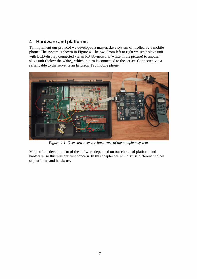
4 Hardware and platforms To implement our protocol we developed a master/slave system controlled by a mobile phone. The system is shown in Figure 4-1 below. From left to right we see a slave unit with LCD-display connected via an RS485-network (white in the picture) to another slave unit (below the white), which in turn is connected to the server. Connected via a serial cable to the server is an Ericsson T28 mobile phone.
Figure 4-1: Overview over the hardware of the complete system.
Much of the development of the software depended on our choice of platform and hardware, so this was our first concern. In this chapter we will discuss different choices of platforms and hardware.
18
4.1 The Server We looked at many different techniques to reach the goal. Our main ideas about the server platform was that it should: • Be an embedded system. Quiet, small and power-efficient. • Run on some sort of Linux-kernel. This is because the availability of supported
hardware and open source software to Linux-related kernels, such as a free Bluetooth protocol stack. A Linux-kernel would also keep the costs down.
• Have two serial ports (one for the remote control, and one to keep contact with the slave-devices).
• Have enough ROM to host our application. • We also looked at power efficiency, Ethernet-support, and the possibility to connect a
display on the board itself, which could be of future interest.
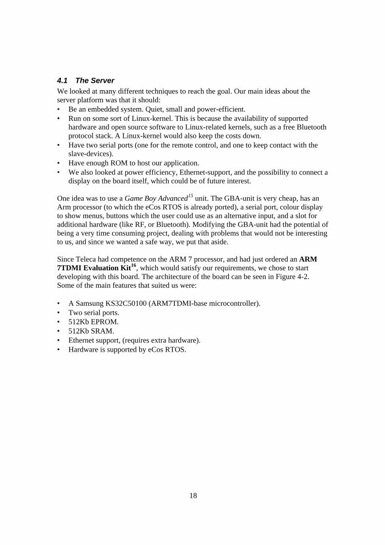
One idea was to use a Game Boy Advanced15 unit. The GBA-unit is very cheap, has an Arm processor (to which the eCos RTOS is already ported), a serial port, colour display to show menus, buttons which the user could use as an alternative input, and a slot for additional hardware (like RF, or Bluetooth). Modifying the GBA-unit had the potential of being a very time consuming project, dealing with problems that would not be interesting to us, and since we wanted a safe way, we put that aside. Since Teleca had competence on the ARM 7 processor, and had just ordered an ARM 7TDMI Evaluation Kit16, which would satisfy our requirements, we chose to start developing with this board. The architecture of the board can be seen in Figure 4-2. Some of the main features that suited us were: • A Samsung KS32C50100 (ARM7TDMI-base microcontroller). • Two serial ports. • 512Kb EPROM. • 512Kb SRAM. • Ethernet support, (requires extra hardware). • Hardware is supported by eCos RTOS.
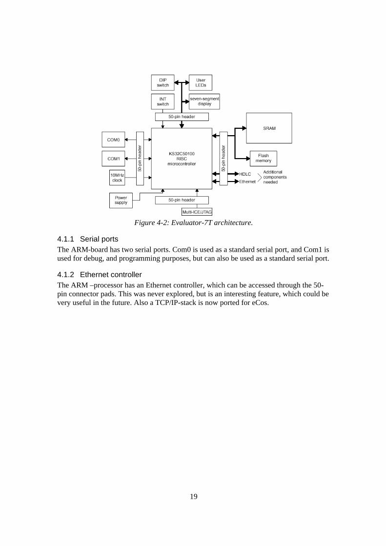
19
Figure 4-2: Evaluator-7T architecture.
4.1.1 Serial ports The ARM-board has two serial ports. Com0 is used as a standard serial port, and Com1 is used for debug, and programming purposes, but can also be used as a standard serial port.
4.1.2 Ethernet controller The ARM –processor has an Ethernet controller, which can be accessed through the 50-pin connector pads. This was never explored, but is an interesting feature, which could be very useful in the future. Also a TCP/IP-stack is now ported for eCos.
20
4.2 eCos
Figure 4-3: eCos logotype
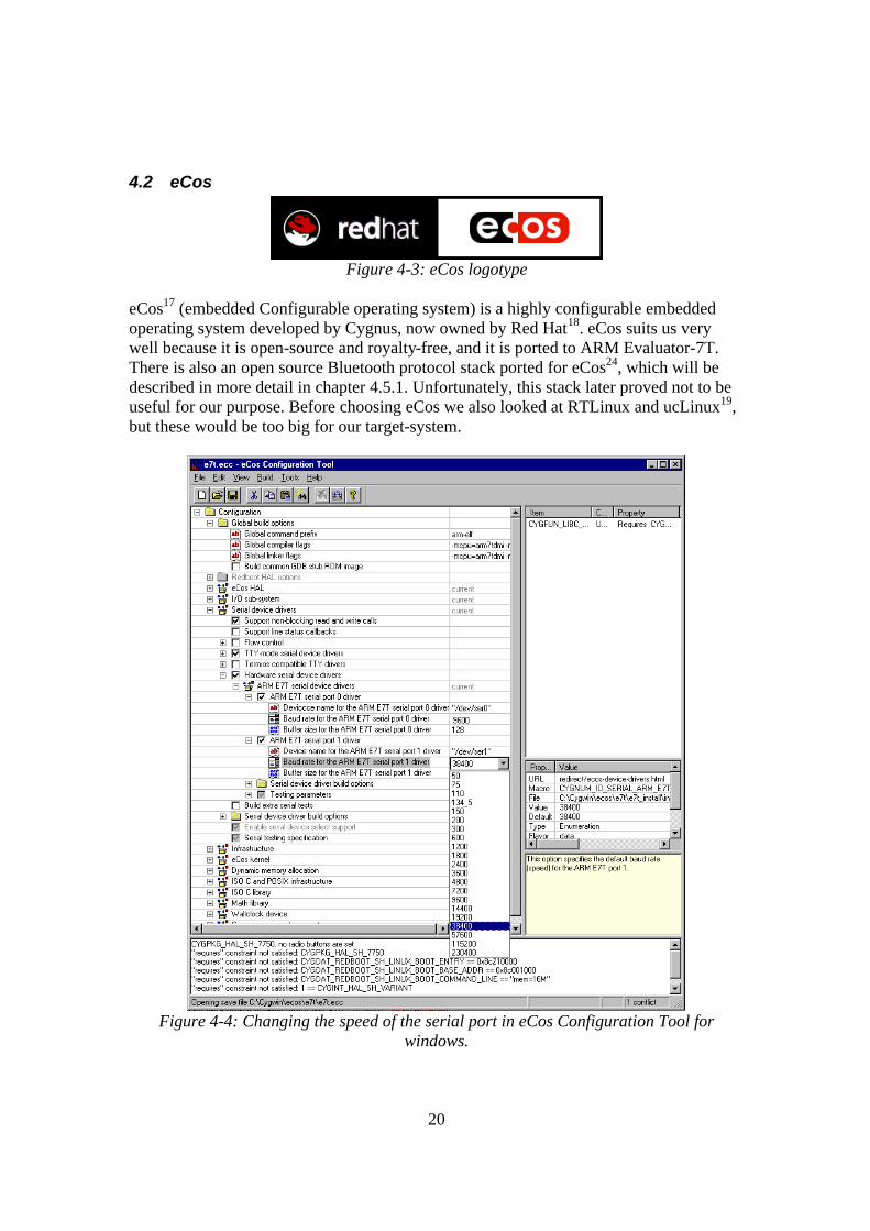
eCos17 (embedded Configurable operating system) is a highly configurable embedded operating system developed by Cygnus, now owned by Red Hat18. eCos suits us very well because it is open-source and royalty-free, and it is ported to ARM Evaluator-7T. There is also an open source Bluetooth protocol stack ported for eCos24, which will be described in more detail in chapter 4.5.1. Unfortunately, this stack later proved not to be useful for our purpose. Before choosing eCos we also looked at RTLinux and ucLinux19, but these would be too big for our target-system.
Figure 4-4: Changing the speed of the serial port in eCos Configuration Tool for
windows.
21
4.2.1 General about eCos eCos is not an operating system in the conventional meaning, but rather it is a library of functions, similar to a hardware layer, which can be accessed when compiling the application. This means that eCos, just as most other RTOS for embedded systems, is not installed on a system, but rather compiled into the application that is going to run on the device. In its smallest form eCos provides basic runtime infrastructure that scales down to between 10 to 100 kilobytes. Of course there is no fancy windows-manager or web-browser included in eCos. In fact, eCos doesn’t even include a telnet-client, or support for hard-drives. Size totally depends on what you choose to support in your application. The size of the kernel should be compared to the smallest possible Linux-kernel, which sizes down to 500 kilobytes of kernel and 1.5MB of RAM, which is to big for our system.
4.2.2 Configuring eCos Configuring eCos (in windows) is done with the eCos Configuration Tool, which is a graphical tree-structure tool seen in Figure 4-4. In the tool you can choose exactly what hardware you want support for, and what you want to leave out to save memory. In Linux, this is done by editing text-files. When configuring eCos is done, the libraries can be built, which later will be used when compiling the application. More information about how to set up and compile for eCos is found in Appendix A.
22
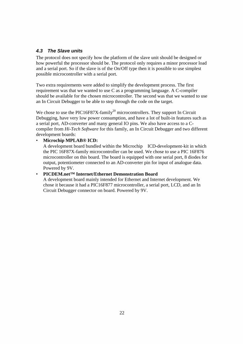
4.3 The Slave units The protocol does not specify how the platform of the slave unit should be designed or how powerful the processor should be. The protocol only requires a minor processor load and a serial port. So if the slave is of the On/Off type then it is possible to use simplest possible microcontroller with a serial port. Two extra requirements were added to simplify the development process. The first requirement was that we wanted to use C as a programming language. A C-compiler should be available for the chosen microcontroller. The second was that we wanted to use an In Circuit Debugger to be able to step through the code on the target. We chose to use the PIC16F87X-family20 microcontrollers. They support In Circuit Debugging, have very low power consumption, and have a lot of built-in features such as a serial port, AD-converter and many general IO pins. We also have access to a C-compiler from Hi-Tech Software for this family, an In Circuit Debugger and two different development boards: • Microchip MPLAB® ICD:
A development board bundled within the Microchip ICD-development-kit in which the PIC 16F87X-family microcontroller can be used. We chose to use a PIC 16F876 microcontroller on this board. The board is equipped with one serial port, 8 diodes for output, potentiometer connected to an AD-converter pin for input of analogue data. Powered by 9V.
• PICDEM.net™ Internet/Ethernet Demonstration Board A development board mainly intended for Ethernet and Internet development. We chose it because it had a PIC16F877 microcontroller, a serial port, LCD, and an In Circuit Debugger connector on board. Powered by 9V.
23
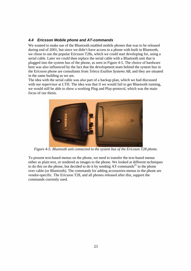
4.4 Ericsson Mobile phone and AT-commands We wanted to make use of the Bluetooth enabled mobile phones that was to be released during end of 2001, but since we didn’t have access to a phone with built in Bluetooth, we chose to use the popular Ericsson T28s, which we could start developing for, using a serial cable. Later we could then replace the serial cable with a Bluetooth unit that is plugged into the system bus of the phone, as seen in Figure 4-5. The choice of hardware here was also influenced by the fact that the development team behind the system bus in the Ericsson phone are consultants from Teleca Exallon Systems AB, and they are situated in the same building as we are. The idea with the serial cable was also part of a backup plan, which we had discussed with our supervisor at LTH. The idea was that if we would fail to get Bluetooth running, we would still be able to show a working Plug and Play-protocol, which was the main focus of our thesis.
Figure 4-5: Bluetooth unit connected to the system bus of the Ericsson T28 phone.
To present text-based menus on the phone, we need to transfer the text-based menus either as plain text, or rendered as images to the phone. We looked at different techniques to do this on the phone, but decided to do it by sending AT-commands21 to the phone over cable (or Bluetooth). The commands for adding accessories-menus to the phone are vendor-specific. The Ericsson T28, and all phones released after this, support the commands currently used.
24
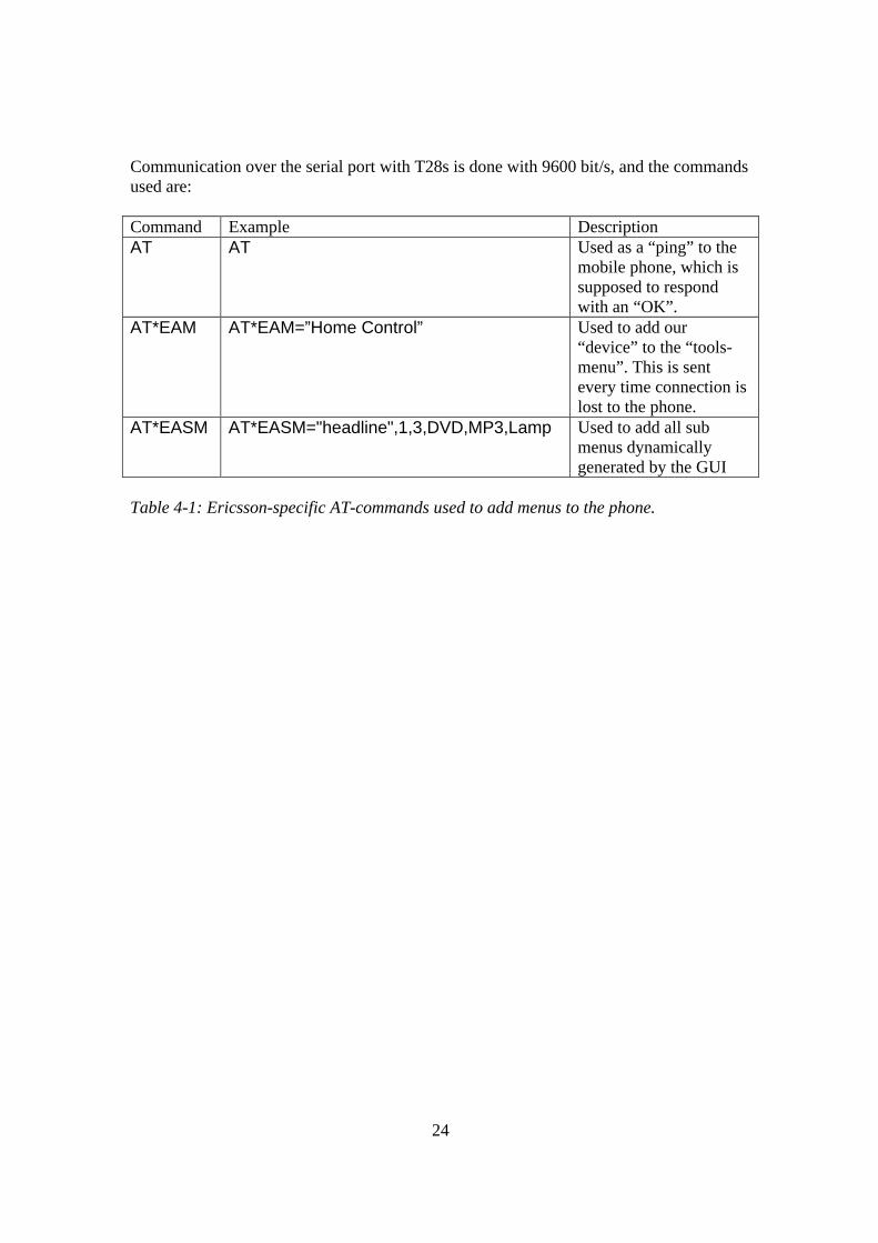
Communication over the serial port with T28s is done with 9600 bit/s, and the commands used are: Command Example Description AT AT Used as a “ping” to the
mobile phone, which is supposed to respond with an “OK”.
AT*EAM AT*EAM=”Home Control” Used to add our “device” to the “tools-menu”. This is sent every time connection is lost to the phone.
AT*EASM AT*EASM="headline",1,3,DVD,MP3,Lamp Used to add all sub menus dynamically generated by the GUI
Table 4-1: Ericsson-specific AT-commands used to add menus to the phone.
25
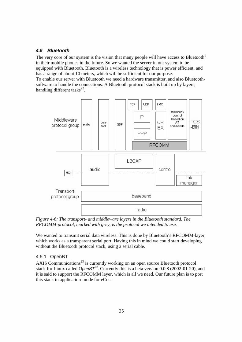
4.5 Bluetooth The very core of our system is the vision that many people will have access to Bluetooth1 in their mobile phones in the future. So we wanted the server in our system to be equipped with Bluetooth. Bluetooth is a wireless technology that is power efficient, and has a range of about 10 meters, which will be sufficient for our purpose. To enable our server with Bluetooth we need a hardware transmitter, and also Bluetooth-software to handle the connections. A Bluetooth protocol stack is built up by layers, handling different tasks22.
Figure 4-6: The transport- and middleware layers in the Bluetooth standard. The RFCOMM-protocol, marked with grey, is the protocol we intended to use. We wanted to transmit serial data wireless. This is done by Bluetooth’s RFCOMM-layer, which works as a transparent serial port. Having this in mind we could start developing without the Bluetooth protocol stack, using a serial cable.
4.5.1 OpenBT AXIS Communications23 is currently working on an open source Bluetooth protocol stack for Linux called OpenBT24. Currently this is a beta version 0.0.8 (2002-01-20), and it is said to support the RFCOMM layer, which is all we need. Our future plan is to port this stack in application-mode for eCos.
26
4.5.2 HelloBT This is Teleca’s Bluetooth protocol stack with support for multiple targets. This stack was not accessible because Teleca did not want to release the code.
4.5.3 WOSP25 (Wireless Open Source Platform) Combitech Systems26 has developed an embedded platform for wireless communication, based on Bluetooth and WAP. In this project an old version of eCos is used on an “Arm evaluation board”, which is an old model of our “Arm Evaluator-7T board”. The Bluetooth protocol stack used is Axis Communications OpenBT-stack, which has been ported to eCos by Combitech Systems, and published by Lars Lindqvist. This looked as a possible solution, when we did our research, but when we tried it, it failed because of the differences between the evaluation boards and the versions of eCos. We tried to modify the stack so that it would work on our board with our new version of eCos, but it was a time consuming project, and we had to put it on ice and focus on the serial cable solution.
4.5.4 Serial cable solution As a backup plan and a temporary test-solution we used an ordinary serial cable between the phone and the serial port of the server. A standard serial cable from Ericsson worked fine as long as we were developing under Windows. When we connected the phone to the ARM then the transmission failed. The reason for this was unsupported Request To Send and Clear To Send handling on the ARM board27. The ARM processor gave the wrong signal and stopped the phone from transmitting any data at all. We had to make a special serial cable to avoid the problem. On this cable we simply omitted the CTS and RTS signals.
27
4.6 Radio RF network solution We wanted a simple and cheap system controlled by the mobile phone. One way to make the system cheap was to use simple RF28 communication between the control unit and the slaves instead of a more expensive Bluetooth solution. The ARM master unit controls the slaves over a radio network or via serial cable. Secure communication, like control of burglar alarm, is done via serial cable to minimise risks. The radio network can be done in two ways: • All communication is done over a single frequency system. This system has the
advantage of being cheap and the disadvantage of being vulnerable to a malfunctioning slave device. One slave can talk continuously and mess up all communication. The master will not be able to reset the system.
• The system uses dual frequencies. It is always possible for the master to command a system reset because the master transmits with one frequency and the slaves transmit on another.
28
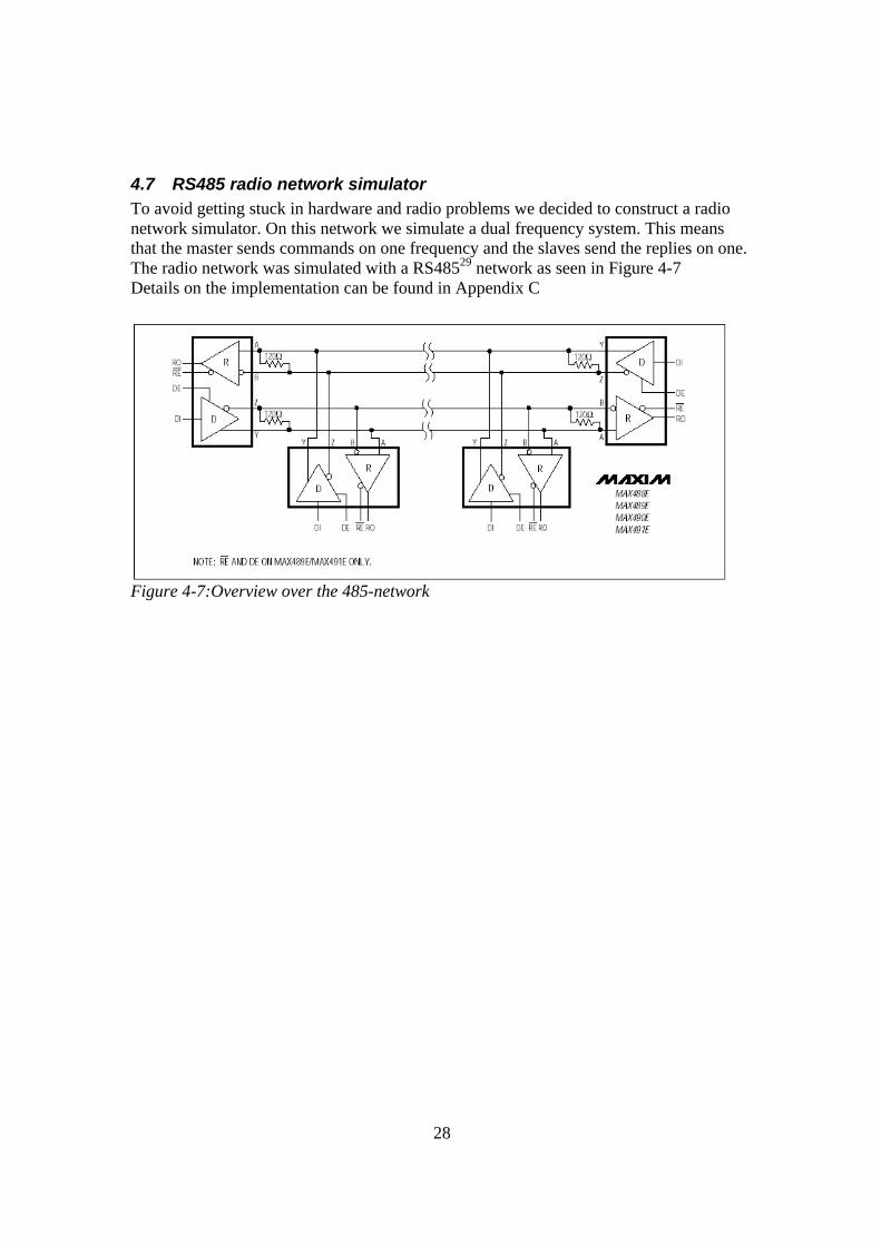
4.7 RS485 radio network simulator To avoid getting stuck in hardware and radio problems we decided to construct a radio network simulator. On this network we simulate a dual frequency system. This means that the master sends commands on one frequency and the slaves send the replies on one. The radio network was simulated with a RS48529 network as seen in Figure 4-7 Details on the implementation can be found in Appendix C
Figure 4-7:Overview over the 485-network
29
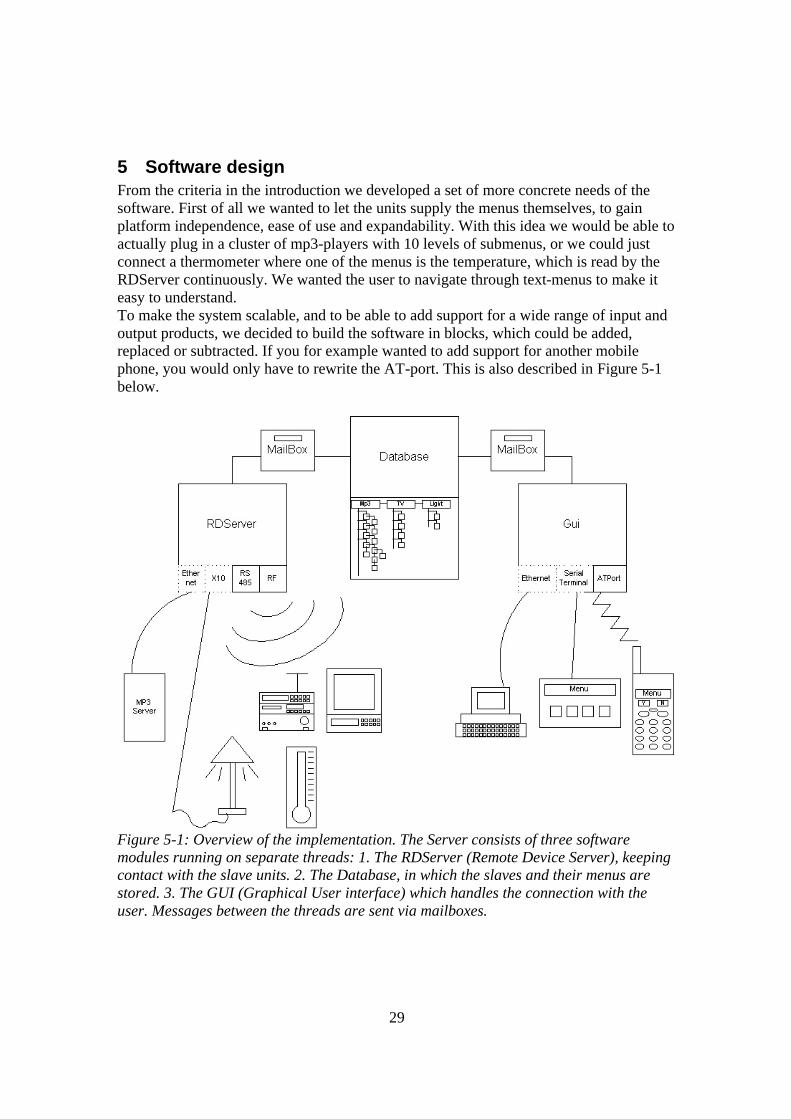
5 Software design From the criteria in the introduction we developed a set of more concrete needs of the software. First of all we wanted to let the units supply the menus themselves, to gain platform independence, ease of use and expandability. With this idea we would be able to actually plug in a cluster of mp3-players with 10 levels of submenus, or we could just connect a thermometer where one of the menus is the temperature, which is read by the RDServer continuously. We wanted the user to navigate through text-menus to make it easy to understand. To make the system scalable, and to be able to add support for a wide range of input and output products, we decided to build the software in blocks, which could be added, replaced or subtracted. If you for example wanted to add support for another mobile phone, you would only have to rewrite the AT-port. This is also described in Figure 5-1 below.
Figure 5-1: Overview of the implementation. The Server consists of three software modules running on separate threads: 1. The RDServer (Remote Device Server), keeping contact with the slave units. 2. The Database, in which the slaves and their menus are stored. 3. The GUI (Graphical User interface) which handles the connection with the user. Messages between the threads are sent via mailboxes.
30
We also wanted the protocol to support an encrypted sequence number that would change over time, to add security. This has not been implemented, but the protocol supports it. To make the system stable we have done the server an independent master. The master will ping for new units on command, and collect menus from the slaves. In this way the system reliability will never be depending upon the implementation of the slaves. To make the different parts of the system independent of each other we also decided to use threads, handled by eCos. The core of the system would be the menu, which is collected from the slave-units, stored and updated continuously in a database, and sent to the user on user command. Thus we need three threads totally separated and independent of each other: Remote Device Server (RD-Server) Pings known slaves, collects the menu systems from the slaves, checks for new slaves on demand, and sends execute-commands to the slaves. Database Stores all the menus in a tree, and makes sure that it is not possible to write and read at the same time. Contains functions for updating, reading and writing to the database. Graphical User Interface (GUI) Keeps track on where in the menu structure the user is navigating, and depending on where, gets the right menus from the database. Pinging the user, and keeping the connection with the user alive.
31
5.1 Hardware Abstraction Layer Starting to developing the application that were to run under eCos on the ARM-board, we soon realised that it would be very time-consuming to download the code to the ARM every time we wanted to try out our ideas, so we decided to create a “Hardware Abstraction Layer (HAL)”, which would make it possible for us to develop the whole application in Microsoft Development Studio. The HAL would contain all the OS-specific functions, and thus give us a set of general functions that were OS independent. Functions controlled by the HAL are: • Thread-handling and initiating • Memory allocation • Setting up the serial ports • Timers • Sending and receiving Data on the serial ports • Handling the Mailboxes The windows-HAL also included the graphical MFC-application that we used for simulating the application. This was because we wanted to be able to give the database a graphical view, so that we could see what devices were detected and get some insight in the processes behind the application, during demonstration. We also wanted to have a comfortable way to debug it. We planned to make an error-handling function, that would present the errors in a graphical form, but we had problems presenting information in a good way using MFC, and it took too much time, so we halted that project, and used the debugger in MS Visual C++ instead, which worked just as well.
32
5.2 GUI
Figure 5-2: The principles of the GUI
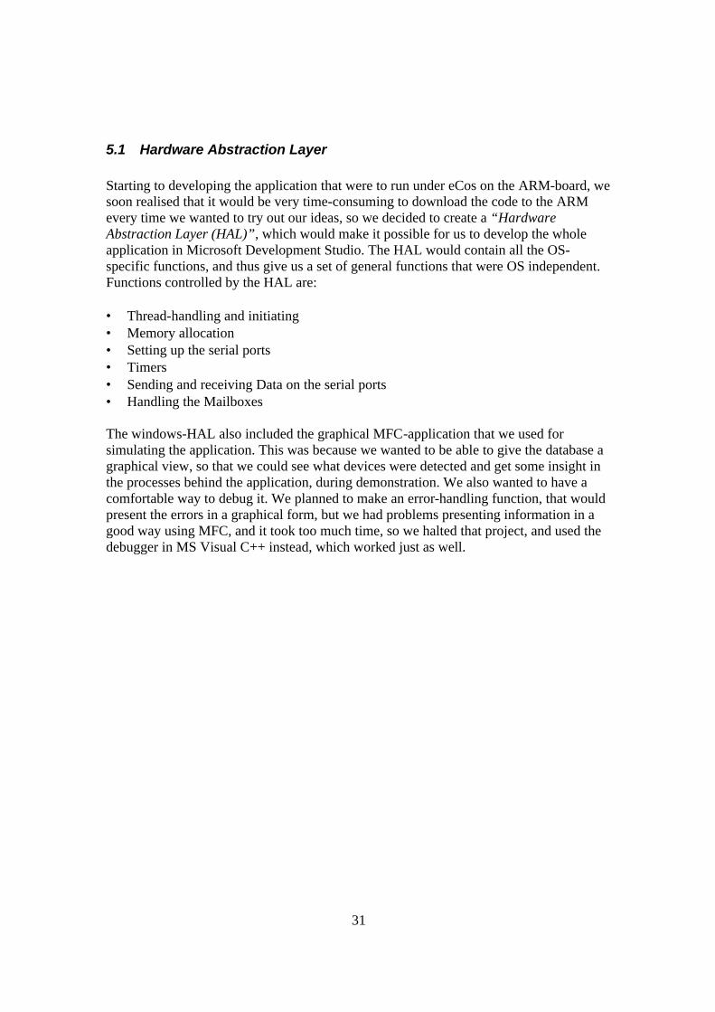
The GUI is responsible for getting the menu, and sending it to the user. Since we did not want to be restricted by just using the phone, we wanted to make the GUI as open as possible, the GUI should just be responsible for the tasks which all control-devices have in common. Which is: • Formatting and sending the submenu to the menu selected by the user. • Keeping track of where in the menu system the user is navigating • Getting the right menu from the database. • Pinging the user • Keeping the connection with the user alive. When sending the menu, the GUI will call on the AT-port, which is the specific module for delivering the menu to our Ericsson T28 phone. This AT-port can be replaced with another port, supporting another phone, or even a serial-interface for a special terminal. When the GUI calls the AT-port it sends the whole menu as a linked list, and the AT-port has the responsibility to arrange the menus and send them to the phone.
33
5.2.1 The GUI’s parent-system The GUI keeps information about what menu the user is navigating on right now, and also the id of the current menu’s parent. In this way, the GUI can get the parent-menu from the database when the user presses “no”, and thus step up in the structure. There are two special cases in the recursive-system: The first occurs when a device’s root menu is listed. In this case the menus will have parent Id set to 0. Then if no is pressed the GUI will list the available devices. The second special case is when no is pressed if the user is on the device-menu. The device-menu’s parent is set (virtually) by the database to “-1”, to indicate that it is the device-menu. When this is the case, and the user presses “no”, the root-menu is sent (Home Control).
5.2.2 Ping user When the remote device is connected, the GUI will constantly check for incoming commands on the AT-port. Every 50’th time it checks the AT-port, it pings the remote device, and if the remote device does not respond, the GUI is placed in a loop of sending the root-menu, to attach itself to the remote device. This is done every two seconds, until the remote device is connected again.
5.3 At-port The AT-port is an Ericsson-specific module that converts the output of the GUI into an AT-command (see above), and sends it to the phone via the Hardware Abstraction Layer (HAL). This module is supposed to be replaceable with for example a TCP/IP-port for remote control over Internet, a serial port, for terminal use, or a TV-port, for controlling via a TV-remote control, and displaying menus on the TV. Parts of the AT-port is now placed in the GUI, which should be changed, but our priority is on getting the software to work, rather than on perfection, so we have left it there for now. Functions supplied by the AT-port are: • Forging the menus to an AT-command. • Handle the echo from the phone. • Making sure that the phone receives the menus ok. • Receiving and interpreting the commands sent from the phone. • Pinging the user.
34
5.4 Database
Figure 5-3: The principles of the Database
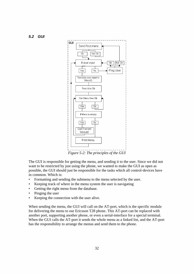
To assure that there is only one part of the system editing the database, we had to make an API for the other threads to read and write to the database, without doing it at the same time. Therefore the database-thread is the only thread that has memory-access to the database itself. The GUI and the RD-server has to use mailboxes, to access the data. The mailboxes are checked by the database-thread, and replied to if needed. The database has a set of functions to edit and use the database. These functions can: • Free memory, by deleting nodes in a menu-tree one by one. • Get parent id from the database. • Remove a device, with it’s appended menus. • Clear Database by removing all devices. • Update the text in a menu. • Remove a menu from the tree. • Return a menu. • Add a Menu to the menu-tree. • Add a Device to the device-tree. When the database lists the devices, the menus returned has parent id set to –1 to indicate that it is the list of devices.
35
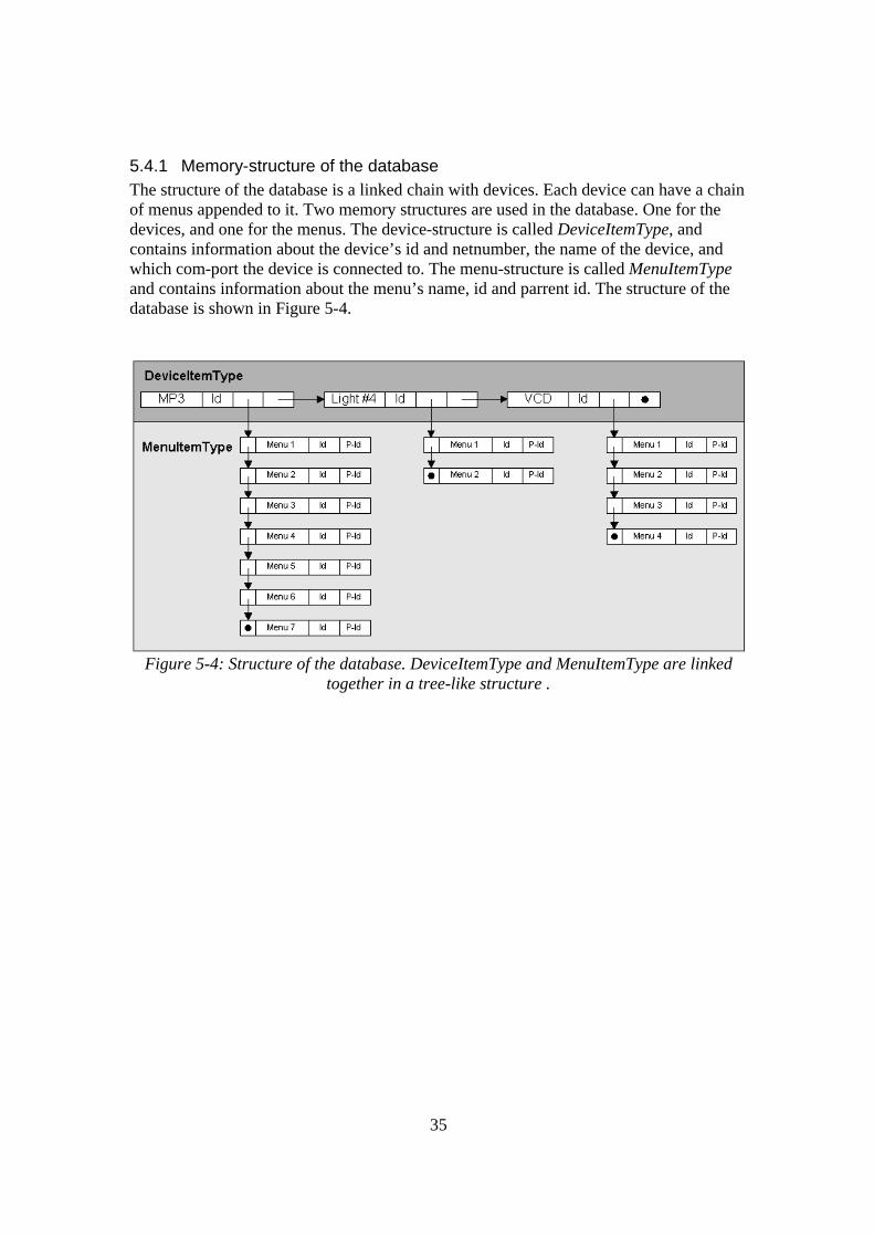
5.4.1 Memory-structure of the database The structure of the database is a linked chain with devices. Each device can have a chain of menus appended to it. Two memory structures are used in the database. One for the devices, and one for the menus. The device-structure is called DeviceItemType, and contains information about the device’s id and netnumber, the name of the device, and which com-port the device is connected to. The menu-structure is called MenuItemType and contains information about the menu’s name, id and parrent id. The structure of the database is shown in Figure 5-4.
Figure 5-4: Structure of the database. DeviceItemType and MenuItemType are linked
together in a tree-like structure .
36
5.5 Remote Device Server (RD Server)
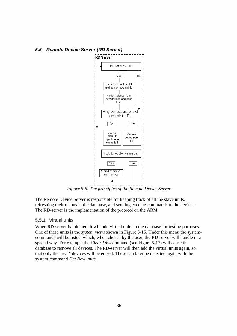
Figure 5-5: The principles of the Remote Device Server
The Remote Device Server is responsible for keeping track of all the slave units, refreshing their menus in the database, and sending execute-commands to the devices. The RD-server is the implementation of the protocol on the ARM.
5.5.1 Virtual units When RD-server is initiated, it will add virtual units to the database for testing purposes. One of these units is the system menu shown in Figure 5-16. Under this menu the system-commands will be listed, which, when chosen by the user, the RD-server will handle in a special way. For example the Clear DB-command (see Figure 5-17) will cause the database to remove all devices. The RD-server will then add the virtual units again, so that only the “real” devices will be erased. These can later be detected again with the system-command Get New units.
37
5.5.2 Detecting new units Next, the RD will call out and ask if there are any units with no id. The RD-server will wait for a fixed time of 4 seconds, and if there was any response, it will ask the database for unused ids, and then assign the ids to the responding devices. To assign the ids to the right devices, the units have to be temporary identified by the server first. This identification is done by temporary random ids taken by the slave units at start-up time together with a random time within the 4-seconds-range. This prevents that all the units respond on the server’s call at the same time. If two devices answer the RD-server with the same id, the RD-server will ignore that id, and ping for new units again, which will force the units to assume other random ids.
5.5.3 Removing Devices The RD-server should also check that the existing units are ok, by pinging them. If they do not respond, they will be removed from the database. In the other end, the slave unit has a timeout, so that if the RD-server does not ping them in a fixed time, they will reset themselves, and respond on the “new unit-ping”.
5.5.4 Refreshing the menus (This function is not implemented in the RD-server as of 2002-03-08, but is supported by the database.) Each unit has a fixed refresh-counter, which is reduced by one in the database, each time the RD-server pings the unit. When the counter reaches zero, the RD-server will get the menus from the unit again. In this way we can acquire information from the slave units, and also keep the menus accurate, even for an mp3-device, where songs and albums keep changing.
5.5.5 Execute commands on the devices The RD-server keeps checking the database for incoming execute-commands, and when received it will also get the NetNr, DeviceId and Menu-id to be executed. This is sent to the device, which will handle the execution of the menu itself.
38
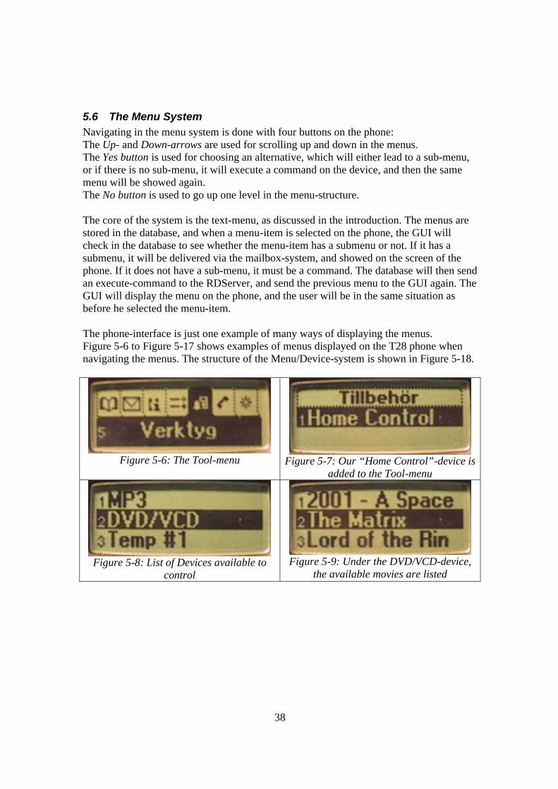
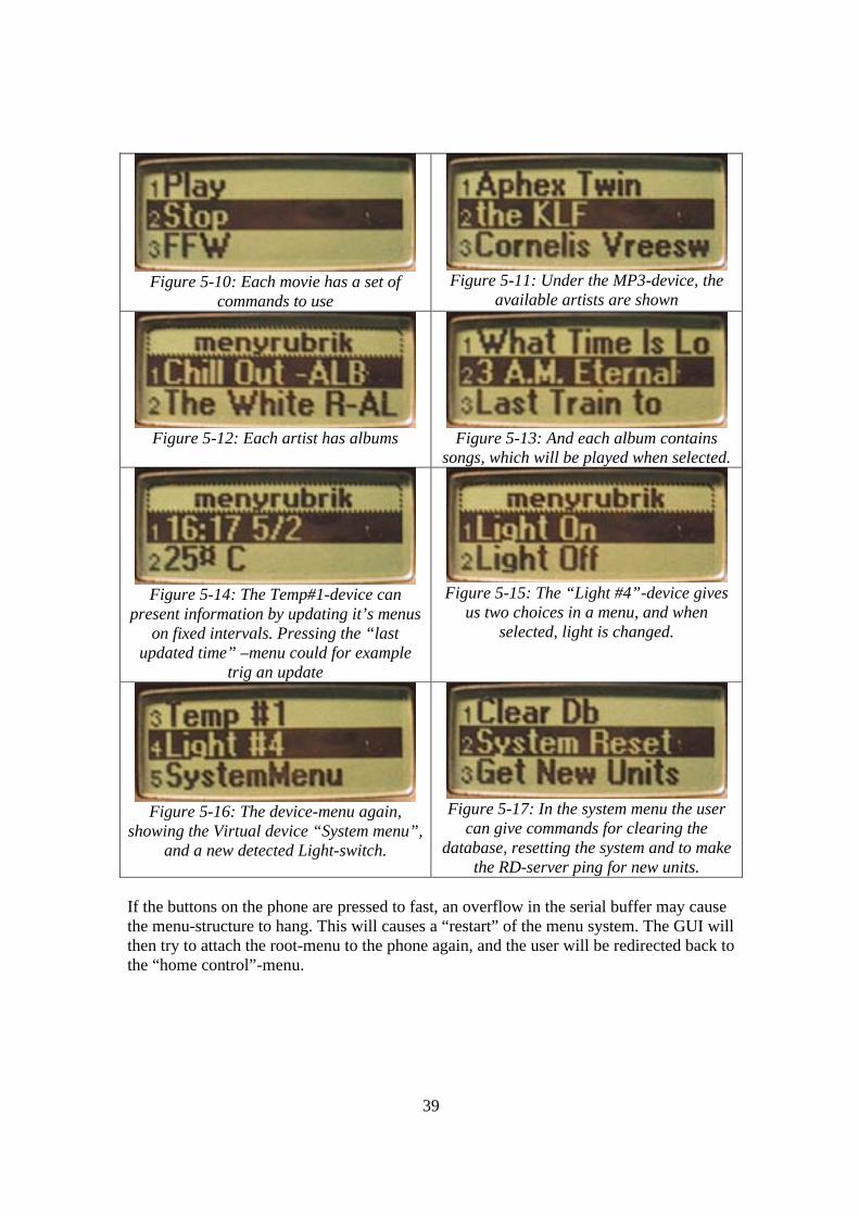
5.6 The Menu System Navigating in the menu system is done with four buttons on the phone: The Up- and Down-arrows are used for scrolling up and down in the menus. The Yes button is used for choosing an alternative, which will either lead to a sub-menu, or if there is no sub-menu, it will execute a command on the device, and then the same menu will be showed again. The No button is used to go up one level in the menu-structure. The core of the system is the text-menu, as discussed in the introduction. The menus are stored in the database, and when a menu-item is selected on the phone, the GUI will check in the database to see whether the menu-item has a submenu or not. If it has a submenu, it will be delivered via the mailbox-system, and showed on the screen of the phone. If it does not have a sub-menu, it must be a command. The database will then send an execute-command to the RDServer, and send the previous menu to the GUI again. The GUI will display the menu on the phone, and the user will be in the same situation as before he selected the menu-item. The phone-interface is just one example of many ways of displaying the menus. Figure 5-6 to Figure 5-17 shows examples of menus displayed on the T28 phone when navigating the menus. The structure of the Menu/Device-system is shown in Figure 5-18.
Figure 5-6: The Tool-menu
Figure 5-7: Our “Home Control”-device is
added to the Tool-menu
Figure 5-8: List of Devices available to
control
Figure 5-9: Under the DVD/VCD-device,
the available movies are listed
39
Figure 5-10: Each movie has a set of
commands to use
Figure 5-11: Under the MP3-device, the
available artists are shown
Figure 5-12: Each artist has albums
Figure 5-13: And each album contains
songs, which will be played when selected.
Figure 5-14: The Temp#1-device can
present information by updating it’s menus on fixed intervals. Pressing the “last
updated time” –menu could for example trig an update
Figure 5-15: The “Light #4”-device gives
us two choices in a menu, and when selected, light is changed.
Figure 5-16: The device-menu again,
showing the Virtual device “System menu”, and a new detected Light-switch.
Figure 5-17: In the system menu the user
can give commands for clearing the database, resetting the system and to make
the RD-server ping for new units. If the buttons on the phone are pressed to fast, an overflow in the serial buffer may cause the menu-structure to hang. This will causes a “restart” of the menu system. The GUI will then try to attach the root-menu to the phone again, and the user will be redirected back to the “home control”-menu.
40
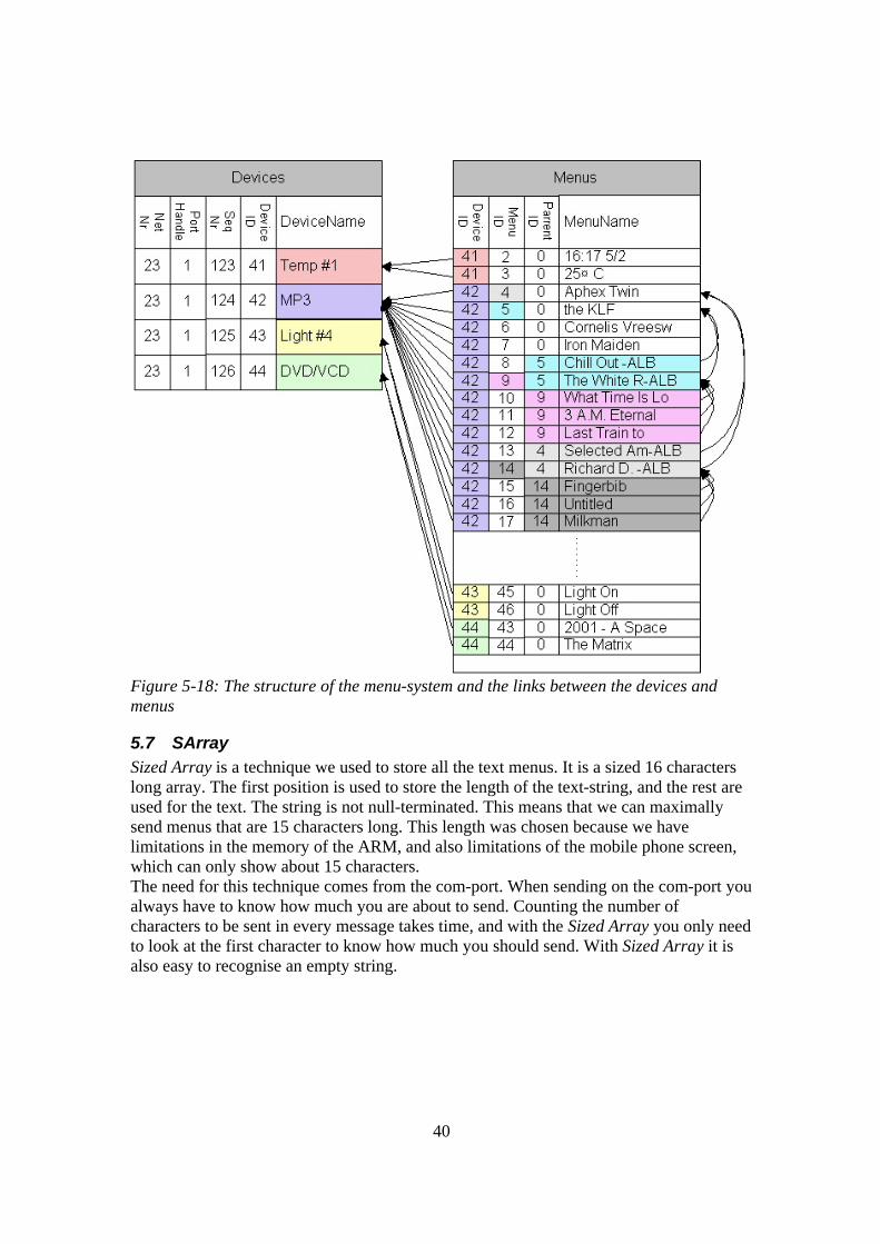
Figure 5-18: The structure of the menu-system and the links between the devices and menus
5.7 SArray Sized Array is a technique we used to store all the text menus. It is a sized 16 characters long array. The first position is used to store the length of the text-string, and the rest are used for the text. The string is not null-terminated. This means that we can maximally send menus that are 15 characters long. This length was chosen because we have limitations in the memory of the ARM, and also limitations of the mobile phone screen, which can only show about 15 characters. The need for this technique comes from the com-port. When sending on the com-port you always have to know how much you are about to send. Counting the number of characters to be sent in every message takes time, and with the Sized Array you only need to look at the first character to know how much you should send. With Sized Array it is also easy to recognise an empty string.

41
5.8 Mailbox System
Figure 5-19: Overview over the mailbox system To communicate between the GUI-, RDServer- and the Database-thread we had to use the shared memory (the heap), and create mailboxes (Figure 5-18). Both eCos and Windows can handle this, but we choose to make another system for 3 reasons: • Ensure that they would work the same way on both windows and eCos • Being able to trace and follow the communication chain • Optimise the mailboxes for our purpose
5.8.1 Mailbox Structures This was done by creating a generic MailBoxType in which a void-pointer to the message itself was stored together with a flag to ensure that the mailbox are not overwritten before it is read.
Figure 5-20: The MailBoxType structure The mailboxes are created and set to NULL before initiation of the threads, and the addresses are sent as parameters to the threads. Each mailbox-address is sent to one thread as inbox, and to the other as outbox. A message has to be stored on the heap and the address has to be type casted to a void-pointer before the address of the message is stored in the mailbox. When the mailbox is read, the message has to be converted back to MessageType again.
42
5.8.2 Mailbox data structures
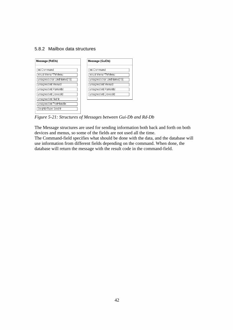
Figure 5-21: Structures of Messages between Gui-Db and Rd-Db The Message structures are used for sending information both back and forth on both devices and menus, so some of the fields are not used all the time. The Command-field specifies what should be done with the data, and the database will use information from different fields depending on the command. When done, the database will return the message with the result code in the command-field.
43
5.9 The Protocol This protocol is specially designed to control a system based on text-menus. The system supported by the protocol is a master- and slave-system, where one master can have up to 65 535 slave units. The protocol also supports as many as 65 535 networks within the range of each other. This is done by the use of net numbers. The protocol specifications can be found in Appendix D - .
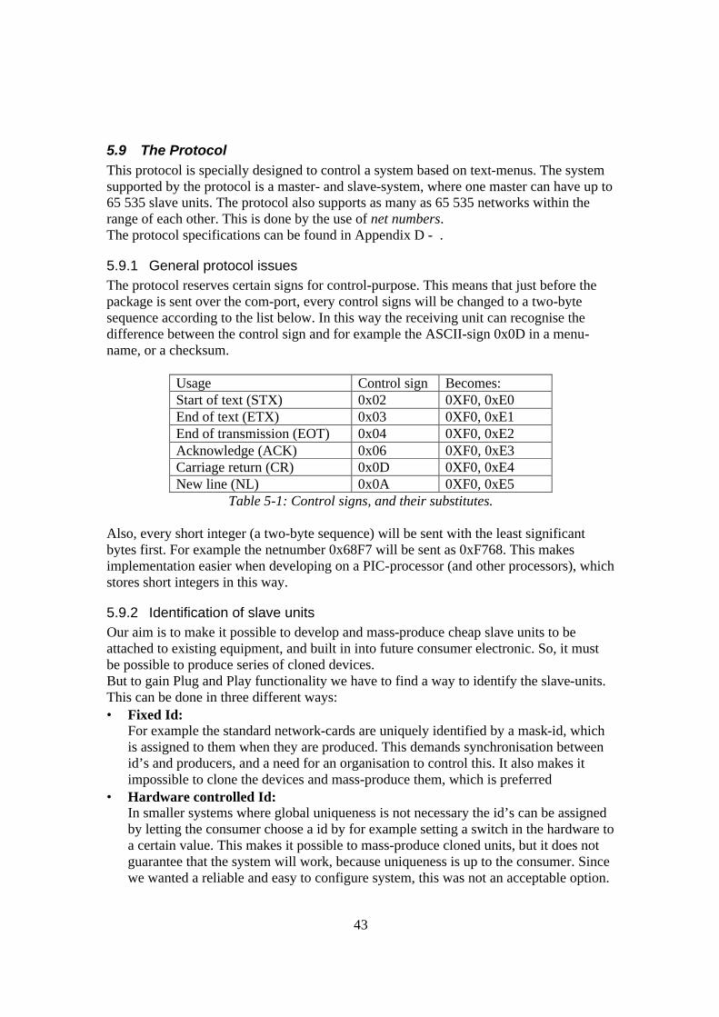
5.9.1 General protocol issues The protocol reserves certain signs for control-purpose. This means that just before the package is sent over the com-port, every control signs will be changed to a two-byte sequence according to the list below. In this way the receiving unit can recognise the difference between the control sign and for example the ASCII-sign 0x0D in a menu-name, or a checksum.
Usage Control sign Becomes: Start of text (STX) 0x02 0XF0, 0xE0 End of text (ETX) 0x03 0XF0, 0xE1 End of transmission (EOT) 0x04 0XF0, 0xE2 Acknowledge (ACK) 0x06 0XF0, 0xE3 Carriage return (CR) 0x0D 0XF0, 0xE4 New line (NL) 0x0A 0XF0, 0xE5
Table 5-1: Control signs, and their substitutes. Also, every short integer (a two-byte sequence) will be sent with the least significant bytes first. For example the netnumber 0x68F7 will be sent as 0xF768. This makes implementation easier when developing on a PIC-processor (and other processors), which stores short integers in this way.
5.9.2 Identification of slave units Our aim is to make it possible to develop and mass-produce cheap slave units to be attached to existing equipment, and built in into future consumer electronic. So, it must be possible to produce series of cloned devices. But to gain Plug and Play functionality we have to find a way to identify the slave-units. This can be done in three different ways: • Fixed Id:
For example the standard network-cards are uniquely identified by a mask-id, which is assigned to them when they are produced. This demands synchronisation between id’s and producers, and a need for an organisation to control this. It also makes it impossible to clone the devices and mass-produce them, which is preferred
• Hardware controlled Id: In smaller systems where global uniqueness is not necessary the id’s can be assigned by letting the consumer choose a id by for example setting a switch in the hardware to a certain value. This makes it possible to mass-produce cloned units, but it does not guarantee that the system will work, because uniqueness is up to the consumer. Since we wanted a reliable and easy to configure system, this was not an acceptable option.
44
• Dynamically allocated id The device has not their id set at manufacture, but instead has an algorithm for assuming an id. This id should be locally unique for the net in which it is to be used. In this way the devices can be cloned, and no organisation has to keep track of all ids.
Most of today’s high-level protocols uses fixed ids, and takes advantage of the lower level IP-protocol. The IP protocol identifies every networkcard with a worldwide unique MAC-address. Another example of fixed Id’s is the LonTalk-protocol (discussed earlier), which uses special hardware where every chip gets a unique id at manufacture. As described in chapter 3.1, the X10 system uses hardware-controlled id by letting the user set a locally unique id with a switch on the device. An advantage, or disadvantage, gained by this is that it gives the user the possibility to control two units with the same id. Our protocol makes use of ids set dynamically by the software.
5.9.3 Net number- and id-commands When a master is initiated it scans the surrounding for a net number that is not in use by another master. This net number will be assumed by the master, and then assigned to all slaves eventually detected by the master. The net number separates each master/slave network. The protocol supports dynamic assignment of the id and net number used to identify each slave unit. The master scans for new units, as described in chapter 5.5.2. A new slave unit takes a random id, as described in chapter 5.10, and replies to the master within a randomly chosen time. The master then chooses a suitable new id and assigns that id and the system net number to that slave. The id and net handling commands are:
• Reset System [RES] • Clear Unit Id [CUI] • Identify New Units [INU] with the reply I Am Blank [IAB] • Set Id and Net [SIN]
5.9.4 Menu- and name-collecting commands The next important property of the protocol is that the system is totally controlled by menus and a corresponding id number to every menu. After assigning id and net number to a slave, the master has to collect a string that describes the slave unit followed by collecting all the menus and their corresponding ids and parent-numbers. The parent-number is used when the menu system is built in the database (see chapter 5.6). The menu and name collecting commands are
• Get Unit Description [GUD] with the reply Unit Description Reply [UDR] • Get Menu/Action [GMA] with the reply Menu/Action Reply [SMR]
5.9.5 Action commands The last property of the protocol is to support commanding the slave to do an action, or execute a command. The master commands the slave to do an action by sending the
45
command “Run Device Action” followed by the id of the specific action. The id of the action is that id which was sent by the slave to the RD-server and stored in the database, as described in chapter 5.6. The slave replies with a “Device Action Reply”. The actions commands are
• Run Device Action [RDA] with the reply Device Action Reply [DAR].
5.9.6 Ping-commands The server should continually check if the units are responding and are online, or else they should be removed. Pings are done with: Ping Unit [PUN] with the reply Ping Unit Reply [PUR]
46
5.10 Design of the slave units The slave units are quite simple in our example. Since the purpose for this thesis is to evaluate the protocol, and not the slaves, there is no reason to develop an advanced slave unit like an mp3-player. The only actions done by the slave units we have developed are some simple ON/OFF control actions. The code has been divided into two layers, just as the code on the server. The lower layer, which is closest to the hardware, is called the hardware layer. Everything that is target specific or happens in real time is allocated in this layer. On top of this layer is the application layer. Everything that is not target specific or does not happen in real time is allocated in this layer.
5.10.1 General design issues due to choice of platform We chose the PIC16F876 & PIC16F877 microcontrollers as previously discussed in the platform section. These microcontrollers are very suitable for simple control applications. They are cheap, have a built in asynchronous serial port (USART), and many general peripheral IO pins and finally they have In Circuit Debugger capability. An In Circuit Debugger is a debugger device that you connect directly to the processor, which supports in circuit, via a serial cable. The processor itself works as the debugger, and from the serial port you can get debug-information. The tricky thing about the PIC16F8XX is its limitations in ram memory, interrupt handling and stack size. This gives a very low level type of programming when the programmer has to learn in detail about the registers and architecture of the microcontroller.
RAM memory: The memory is quite small and divided into banks. This can make the access of the variables and the handling of the RAM resources a bit tricky.
Stack size: The PIC16F8XX has a hardware stack. Here, the stack refers to an area of the memory where the computer temporary stores data when a more important task has to be taken care of. When the more important task has been carried out, the less important task is resumed. A stack works according to the principle Last In First Out (LIFO). The stack on these microcontrollers has a fixed stack depth of 8 positions and does not support push- or pop-commands. Push is a software command that puts data on the top of the stack. Pop is a software command that gets data from the top of the stack. In these microcontrollers you put the return address on the stack when you jump to a sub- or interrupt-routine, and when you return from the sub- or interrupt-routine you get the return address from the stack. Otherwise you have no access to the hardware stack. The lack of these commands forces the programmer to keep track of the maximal stack depth the code needs to use, and makes it hard to work around a stack overflow.
Interrupt handling: Interrupt is a routine initiated by the hardware. This is the fastest way a computer can react to a request of service from the hardware. The address where the service routine
47
starts upon an interrupt is stored in an interrupt vector. In the microcontrollers, which we have chosen to use, there exist only one interrupt vector. As a result of this the programmer has to poll continually for the interrupt-flags to find the reason for the interrupt. If something went wrong during the initialisation of the microcontroller you might have a ghost interrupt that disturbs and blocks some interrupt.
5.10.2 The Application layer This layer polls the timeouts and the serial port for incoming messages. It also handles all the received commands and the corresponding replies. This layer is generally written, and calls upon the hardware layer.
5.10.3 The Hardware layer The hardware layer has to support the ON/OFF actions and the communication protocol. It is the hardware layer that is responsible for the initialisation and configuration of the microcontroller. The interrupt service routines are also allocated within the hardware layer. The following functionality is handled by the hardware layer:
• Sending and transmission of messages on the serial port. • Unit Address detection in the USART interrupt service routine. • Control and message validation in the USART interrupt service routine
(checksum and sequence number). • Sending ON/OFF signals to the diodes and the relays. • Sending start transmission-signal to the radio unit. • The unlocking timers. • The locking waits. • The tick counters. • A-D conversions. • The real time clocks. • Calculating random numbers. • Calculating new sequence numbers. • Prepare the reply-message with correct sequence number address and other basic
protocol data.
5.10.4 Weak points Some things are not correctly supported by the slave units. Right now it is possible to get control and get replies from unassigned units even though it should be disabled. An unassigned unit should not accept controlling commands. We also have not implemented the use of Device Action Reply[DAR]
48
6 Result To implement and test our protocol, we have built a prototype system with an ARM-processor, Ericsson T28, a PIC-processor with a LCD-display, and a PIC-processor with LEDs mounted on the card. Between the slaves and the server we wanted to use serial communication over radio, but this was a later question, so we simulated a radio-network by using RS-485 as described in chapter 4-7. Between the mobile phone and the server we wanted to use a Bluetooth-link, but we did not have time enough to make the Bluetooth protocol stack work on eCos. We put it aside, and focused on making the protocol work. Instead of Bluetooth we used a serial cable between the phone and the ARM.
6.1 The test The protocol has been tested successfully with the prototype system. This was done in the following way:
1. Downloading the code to the server, and start it via hyperterm. This will not be necessary when the code is stored in the flash-memory (see chapter 4.1).
2. Connecting the mobile phone to the server via a serial cable simulating Bluetooth connection. The server will detect the phone, and add itself under the “tool”-menu.
3. Powering up two slave units, connected in a RS-485-network, and connecting them to the other serial port of the server. This will simulate that the two slave units are turned on and brought within radio-contact radius with the server.
4. Checking the (virtual) units on the mobile phone, and notice what units are there (no real units yet)
5. Navigating the phone to the system menu, pressing Get New Units command making the server check for new units.
6. Wait for the 4-second long interval and an extra 1-second to get all transmission done.
7. Navigating back to the root-menu, checking for new units in the list. 8. Navigating in the menus of the newly detected units, turning on and off the diodes
of the units. The test is successfully completed, and our desired system is working!
49
7 Discussion Looking back on our specifications in the introduction: Is our system cheap and easy to implement? Our system is cheap to implement. A server unit would cost less than $200 on the market, and the slave units can be mass-produced easily. Hardware for our prototype slave unit cost less than $20, and this will drop when mass-produced. Software is easily developed with freeware tools, and no organisation is needed to keep track of unique ids of the slaves. Is it scalable to fit more complex controller-situations? The protocol handles 65 535 units in 65 535 nets. The limit of the menu depth is right now set to 10, but this can easily be changed by a parameter in the source code. Support for different protocols for example X10 system and Ethernet-connections can be added, but is not yet implemented. Is it controllable by any Menu based unit? Since the software is open and built up in blocks support for other mobile phones, or general graphic interfaces is possible. Support for controlling the server via a computer-terminal over serial cable is being developed. Is it Plug and Play-enabled? From the test above, yes! Does it have optional Security? The protocol supports security with sequence numbers, but the traffic is not encrypted. Serial cables can be used for secure transmission of sensitive information to, for example, an alarm. Does it have Wireless support? Not implemented, but proved to work between server and slaves. Is it power efficient? Both server and slave unit runs on 9V, has no moving parts and no hard drives. The slave unit consumes about 5mA, and run on battery power. The master uses a power eliminator capable of delivering 300mA. Is it open and platform independent? The protocol puts no restrictions whatsoever on the implementation, and so, is platform independent. Our implementation is open source, and is open to others to implement. And finally does it work smooth and stable? The time from selecting a menu, until getting the next one, is acceptable when communicating over a serial cable. The Bluetooth solution has not yet been tested. The system has some software bugs in both the server application and the slave units, but it is nothing related to the protocol, and they can and will be fixed to speed up the system. We have yet to try out how our system works when there are very many slaves. The database may have memory-leakage, and there may be bugs that we do not yet know of. Simulating a big client-network with the PC connected to the server’s serial port can test this. We are already working on this project at the time of writing.
50
Summarizing, we are satisfied with our results. With more time, we could have implemented the system wirelessly.
7.1 Expandability and Usefulness Developing the wireless support, fixing the bugs, and creating good clients would make this product useful in many areas. Connecting it to an alarm system would be a good example of its advantages. The most interesting areas of use are of course where a consumer is faced with new products with interfaces he or she is not familiar with, and where many people needs to control the same equipment remotely. This can be useful in many workplaces for example in the industry, or on hotels or hospitals. Also, the applications in home control situations are in numerous. Our next goal is to get the system running with Bluetooth enabled. Preferable with the OpenBT-stack ported to eCos. This will probably be done in application-mode, and not as a stack, because it is easier. Another goal is to develop a client running on a PC. For example an mp3-player. This would probably not be much work, and it would be a good way to demonstrate the usefulness and capabilities of our protocol. One problem with this application is that the time to transmit all the menu-data from the client to the server might be too big for the system if the mp3-list is very long. Then we have to implement an intelligent mp3-client, which just sends an update on the mp3s that has been changed, so that it doesn’t have to send the whole mp3-list every time the archive is changed. Further development would include support for other techniques. For example the X10 system would be a good way to broaden the usefulness of the system in home control situations. Support for other mobile phones would also be a good way to make the system more useful.
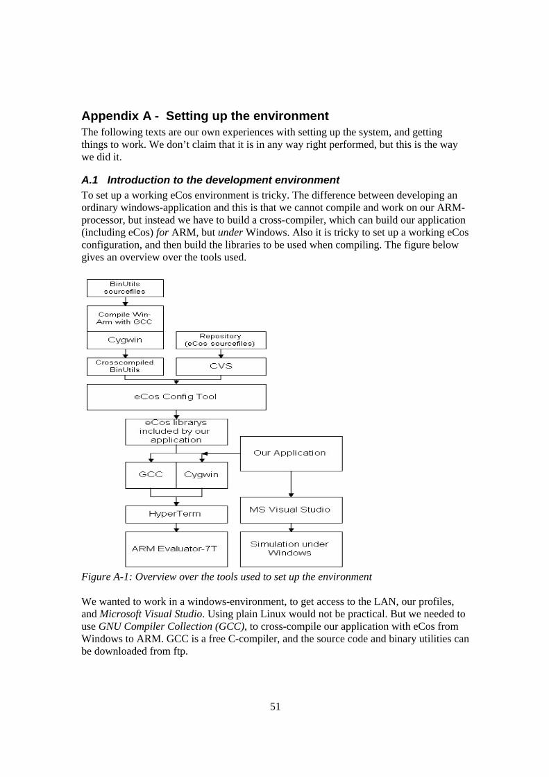
51
Appendix A - Setting up the environment The following texts are our own experiences with setting up the system, and getting things to work. We don’t claim that it is in any way right performed, but this is the way we did it.
A.1 Introduction to the development environment To set up a working eCos environment is tricky. The difference between developing an ordinary windows-application and this is that we cannot compile and work on our ARM-processor, but instead we have to build a cross-compiler, which can build our application (including eCos) for ARM, but under Windows. Also it is tricky to set up a working eCos configuration, and then build the libraries to be used when compiling. The figure below gives an overview over the tools used.
Figure A-1: Overview over the tools used to set up the environment We wanted to work in a windows-environment, to get access to the LAN, our profiles, and Microsoft Visual Studio. Using plain Linux would not be practical. But we needed to use GNU Compiler Collection (GCC), to cross-compile our application with eCos from Windows to ARM. GCC is a free C-compiler, and the source code and binary utilities can be downloaded from ftp.
52
To run GCC under windows, we installed Cygwin, which is an UNIX environment, developed by RedHat, for windows. Cygwin emulates UNIX, and gives a UNIX/Linux look and feel. The GCC has a graphical user interface called Insight, which you might want to use. We downloaded and installed it, but never used it. To configure eCos we used eCos Configuration tool installed under windows. The Configuration tool used the binary utilities that we built with to cross-compile the code to ARM under windows. That we had built with repository downloaded from the CVS. We also used Hyperterm provided with windows. We have had problems with it, and it is worth knowing that Hyperterm does not always display exactly what is sent or received on the com-ports.
53
A.2 Cygwin Download the latest version from: http://sources.redhat.com/cygwin/ We used version 2.78.2.9 for our setup, which installed version 1.3.2 of the file “cygwin.dll”. In Cygwin will create a directory structure, which is referred to as root. Everything Cygwin does is “above” windows, and for example if you give the command “ls” as in UNIX, you will execute the file ls.exe that is located in for example c:\cygwin\bin\. In addition to .exe-files you can also execute .bat files and alike.
A.3 Cross compiling the compiler for ARM
A.3.1 Downloading necessary files Compiling for the ARM is done one a PC running windows, and thus we need a GNU C-compiler which compiles for ARM on a windows-machine30. This cross-compiler has to be built from the following source files: Source files for binutils from: ftp://sunsite.auc.dk/mirrors/gnu/binutils/ (we used binutils-2.10.1.tar.gz) Two source file-archives for GCC from: ftp://sunsite.auc.dk/mirrors/gnu/gcc/ (we used gcc-core-2.95.2.tar.gz and gcc-g++-2.95.2.tar.gz) Eventually the source files for insight from: ftp://sunsite.org.uk/Mirrors/sourceware.cygnus.com/pub/gdb/releases/ (we used insight-5.0.tar.gz ) Extract the files with existing file structure into separate directories. If you are asked to overwrite a file named .brik, do so.
54
A.3.2 Preparations Start a cygwin-shell, give the command “mount”, and check if the directory /tmp is mounted in binmode. If /tmp is not explicitly listed, then the root-directory must be in binmode. If /tmp or / (if /tmp is not listed) is mounted in text-mode, give the command: mount -f -b c:/cygwin/tmp /tmp Download the following patches: ecos-gcc-2952.pat insight-tcl.pat (if you want to use Insight). Apply the patches by using the commands: tr -d '\r' < ecos-gcc-2952.pat | patch -p0 tr -d '\r' < insight-tcl.pat | patch -p0 Go to the directory where you unzipped the gcc-sourcefile. (In our case: /src/gcc/gcc-2.95.2) and correct the dates of the files that we just patched. contrib/egcs_update –touch
55
A.3.3 Building the tools Check that the GCC-library are listed in the PATH, and that it is listed before the current library -/. Use the commands: which gcc env | grep PATH Avoid using spaces in the names of the libraries used when binutils and gcc is built. And if Cygwin is used, run following command: export MAKE_MODE=UNIX The following instructions will build the tools in the directory /tmp/build, and then install them in the directory /tools Configure GNU Binuntils: mkdir -p /tmp/build/binutils cd /tmp/build/binutils /src/binutils/binutils-2.10.1/configure --target=arm-elf \ --prefix=/tools \ --exec-prefix=/tools/H-i686-pc-cygwin \ -v 2>&1 | tee configure.out Build and install the tools: make -w all install 2>&1 | tee make.out Configure GCC PATH=/tools/H-i686-pc-cygwin/bin:$PATH ; export PATH mkdir -p /tmp/build/gcc cd /tmp/build/gcc /src/gcc/gcc-2.95.2/configure --target=arm-elf \ --prefix=/tools \ --exec-prefix=/tools/H-i686-pc-cygwin \ --with-gnu-as --with-gnu-ld --with-newlib \ -v 2>&1 | tee configure.out Build and install GCC: make -w all-gcc install-gcc LANGUAGES="c c++" 2>&1 | tee make.out Configure Insight: mkdir -p /tmp/build/gdb cd /tmp/build/gdb /src/gdb/insight-5.0/configure --target=arm-elf \ --prefix=/tools \ --exec-prefix=/tools/H-i686-pc-cygwin \ -v 2>&1 | tee configure.out Build and install Insight: make -w all install CC='gcc -mwin32' 2>&1 | tee make.out If everything is done correctly, the development tools for the ARM will be placed in /tools/H-i686-pc-cygwin/bin This path should also be exported to PATH. This path is also used by eCos configuration tool.
56
A.4 CVS Since new versions, drivers and ports are constantly developed for eCos, CVS (Concurrent Version System)31 source repository is used to get the most up to date version. It has been very important for us to get the latest version available, since the ARM7-board we used was very new, and drivers and hardware support was released every week. CVS is an open standard for version control, and you need a client, a user and a password to be able to download from the CVS. A free client can be found on: http://www.cvshome.org/ This client is run from the command line, and can be used under Cygwin. Introduction to CVS can be found on this address: http://www.cvshome.org/docs/blandy.html When the client is installed, you can login to the CVS server by typing: cvs –d :pserver:[email protected]:/cvs/ecos login in the Cygwin shell, and then type anoncvs as password. This command is run once, and then the login information is saved for future sessions. Downloading the latest eCos source is done with the command: cvs -d :pserver:[email protected]:/cvs/ecos -z 6 co -P ecos
57
A.5 eCos Configuration Tool When the binutilities are built as described above, the next step is to build the eCos Libraries using the tools we just built. Download and install eCos Configtool version 1.3.1, available for download from: ftp://sources.redhat.com/pub/ecos/eCos131.exe Update the configtool to the latest version 1.3.1.3, which is available for download at: ftp://sources.redhat.com/pub/ecos/anoncvs/Configtool-011025.exe Unzip the file, and replace the exe-file placed in C:\Program Files\Red Hat\eCos\tools\bin\configtool.exe with the new one. Then run the .reg-file. Download the latest version of the eCos repository from the CVS, as described above Start the Packege Administration Tool, and click repository, and choose the directory where your new eCos repository is. (for example C:\Program Files\Red Hat\cvs\) Start eCos configtool and set the search path for the tools under Tools/paths/buildtools to where the tools that has been built are located (for example C:\Cygwin\tools\H-i686-pc-cygwin\bin ). Set the searchpath for Cygwins “linux-tools” under Tools/paths/usertools (for example C:\Cygwin\bin ) Open a template under Build/Templates and choose "ARM Evaluator7T board (AEB-2)" Navigate to /Serial device drivers/, and enable the Hardware serial device drivers, if it is not already done. Save your settings as an .ecc-file Compile the eCos libraries under Build/Library
58
A.6 Building the application and loading it to the board Now, we have a compiler, and we have the eCos-libraries to include in the c-files we have developed under windows. So, we have chosen to save the MS Visual studio project in a subfolder included in the Cygwin-root (for example C:\Cygwin\home\Administrator\ecos\020228-BTRouter ). In this way we can both compile the source files in MS Visual studio, and also compile them for ARM under Cygwin using the following line written as one line32: /tools/H-i686-pc-cygwin/bin/arm-elf-gcc.exe -I/c/eCos/AEB2_2_configtool_011017_install/include serial.c -L/c/eCos/AEB2_2_configtool_011017_install/lib -Ttarget.ld -nostdlib then convert it to binary with the command: /tools/H-i686-pc-cygwin/bin/arm-elf-objcopy.exe -O srec a.out a.bin Then open Hyperterm, and connect the ARM-board to the serial port at 38400 Bps, reboot the ARM-board, and type: load -m xmodem Send the file via Xmodem, and type “go”.
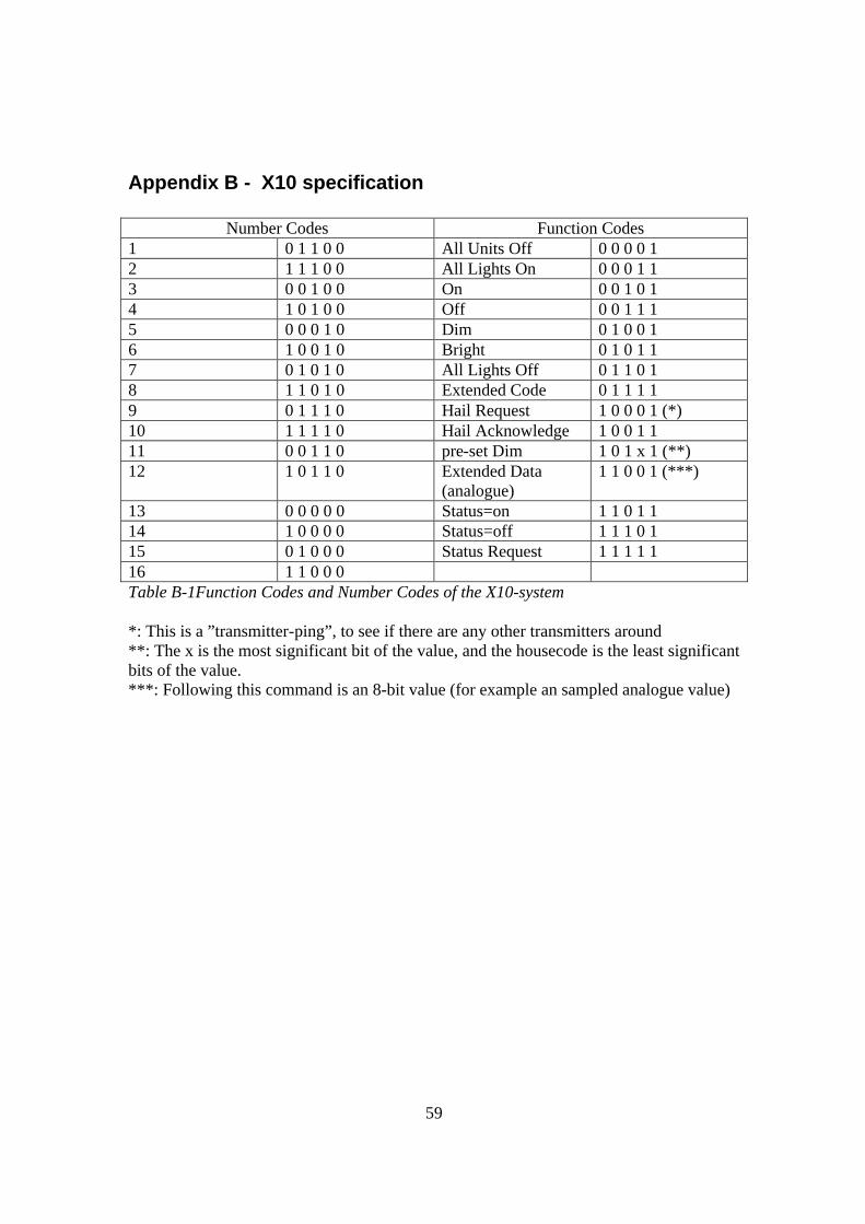
59
Appendix B - X10 specification
Number Codes Function Codes 1 0 1 1 0 0 All Units Off 0 0 0 0 1 2 1 1 1 0 0 All Lights On 0 0 0 1 1 3 0 0 1 0 0 On 0 0 1 0 1 4 1 0 1 0 0 Off 0 0 1 1 1 5 0 0 0 1 0 Dim 0 1 0 0 1 6 1 0 0 1 0 Bright 0 1 0 1 1 7 0 1 0 1 0 All Lights Off 0 1 1 0 1 8 1 1 0 1 0 Extended Code 0 1 1 1 1 9 0 1 1 1 0 Hail Request 1 0 0 0 1 (*) 10 1 1 1 1 0 Hail Acknowledge 1 0 0 1 1 11 0 0 1 1 0 pre-set Dim 1 0 1 x 1 (**) 12 1 0 1 1 0 Extended Data
(analogue) 1 1 0 0 1 (***)
13 0 0 0 0 0 Status=on 1 1 0 1 1 14 1 0 0 0 0 Status=off 1 1 1 0 1 15 0 1 0 0 0 Status Request 1 1 1 1 1 16 1 1 0 0 0 Table B-1Function Codes and Number Codes of the X10-system *: This is a ”transmitter-ping”, to see if there are any other transmitters around **: The x is the most significant bit of the value, and the housecode is the least significant bits of the value. ***: Following this command is an 8-bit value (for example an sampled analogue value)
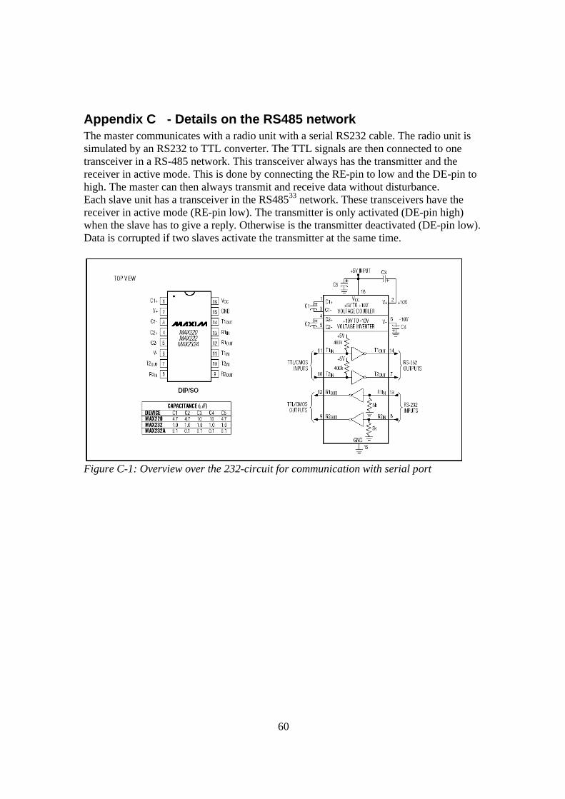
60
Appendix C - Details on the RS485 network The master communicates with a radio unit with a serial RS232 cable. The radio unit is simulated by an RS232 to TTL converter. The TTL signals are then connected to one transceiver in a RS-485 network. This transceiver always has the transmitter and the receiver in active mode. This is done by connecting the RE-pin to low and the DE-pin to high. The master can then always transmit and receive data without disturbance. Each slave unit has a transceiver in the RS48533 network. These transceivers have the receiver in active mode (RE-pin low). The transmitter is only activated (DE-pin high) when the slave has to give a reply. Otherwise is the transmitter deactivated (DE-pin low). Data is corrupted if two slaves activate the transmitter at the same time.
Figure C-1: Overview over the 232-circuit for communication with serial port
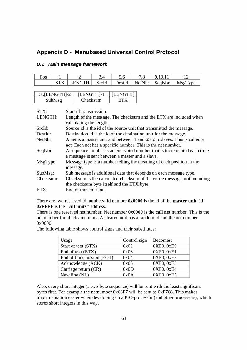
61
Appendix D - Menubased Universal Control Protocol
D.1 Main message framework
Pos 1 2 3,4 5,6 7,8 9,10,11 12 STX LENGTH SrcId DestId NetNbr SeqNbr MsgType
13..[LENGTH]-2 [LENGTH]-1 [LENGTH]
SubMsg Checksum ETX STX: Start of transmission. LENGTH: Length of the message. The checksum and the ETX are included when
calculating the length. SrcId: Source id is the id of the source unit that transmitted the message. DestId: Destination id is the id of the destination unit for the message. NetNbr: A net is a master unit and between 1 and 65 535 slaves. This is called a
net. Each net has a specific number. This is the net number. SeqNbr: A sequence number is an encrypted number that is incremented each time
a message is sent between a master and a slave. MsgType: Message type is a number telling the meaning of each position in the
message. SubMsg: Sub message is additional data that depends on each message type. Checksum: Checksum is the calculated checksum of the entire message, not including
the checksum byte itself and the ETX byte. ETX: End of transmission. There are two reserved id numbers: Id number 0x0000 is the id of the master unit. Id 0xFFFF is the "All units" address. There is one reserved net number: Net number 0x0000 is the call net number. This is the net number for all cleared units. A cleared unit has a random id and the net number 0x0000. The following table shows control signs and their substitutes:
Usage Control sign Becomes: Start of text (STX) 0x02 0XF0, 0xE0 End of text (ETX) 0x03 0XF0, 0xE1 End of transmission (EOT) 0x04 0XF0, 0xE2 Acknowledge (ACK) 0x06 0XF0, 0xE3 Carriage return (CR) 0x0D 0XF0, 0xE4 New line (NL) 0x0A 0XF0, 0xE5
Also, every short integer (a two-byte sequence) will be sent with the least significant bytes first. For example the netnumber 0x68F7 will be sent as 0xF768. This makes implementation easier when developing on a PIC-processor (and other processors), which stores short integers in this way.
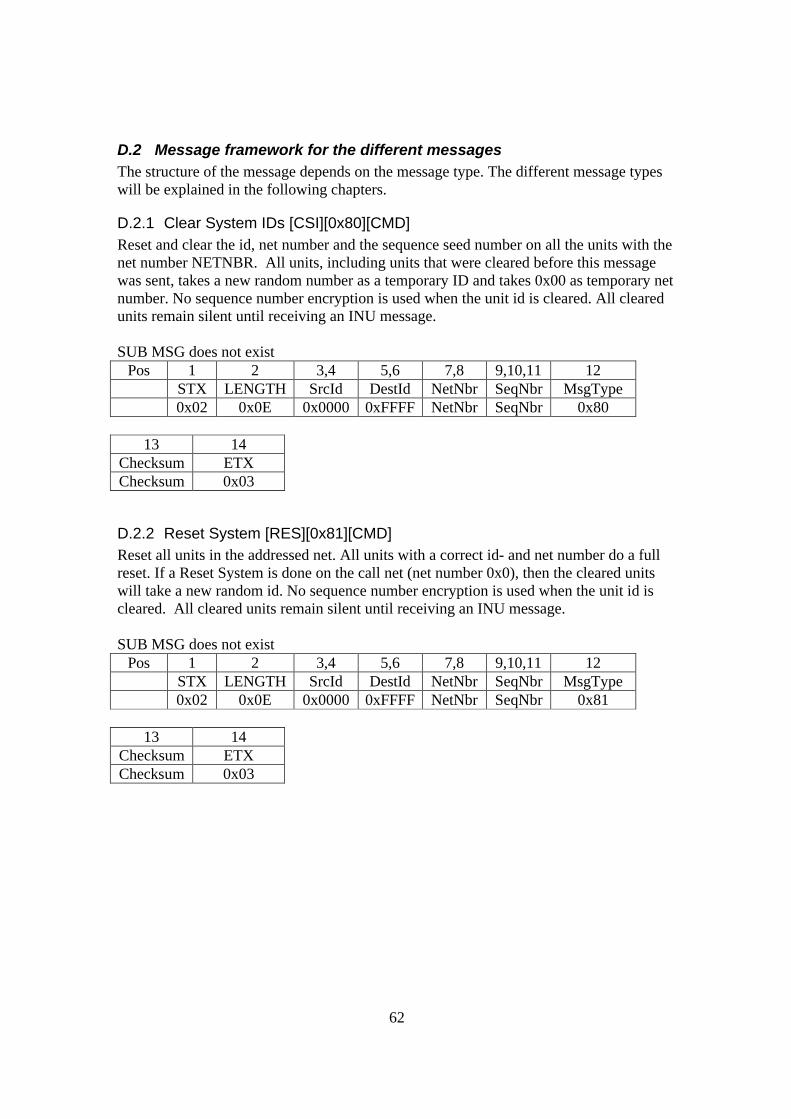
62
D.2 Message framework for the different messages The structure of the message depends on the message type. The different message types will be explained in the following chapters.
D.2.1 Clear System IDs [CSI][0x80][CMD] Reset and clear the id, net number and the sequence seed number on all the units with the net number NETNBR. All units, including units that were cleared before this message was sent, takes a new random number as a temporary ID and takes 0x00 as temporary net number. No sequence number encryption is used when the unit id is cleared. All cleared units remain silent until receiving an INU message. SUB MSG does not exist
Pos 1 2 3,4 5,6 7,8 9,10,11 12 STX LENGTH SrcId DestId NetNbr SeqNbr MsgType 0x02 0x0E 0x0000 0xFFFF NetNbr SeqNbr 0x80
13 14
Checksum ETX Checksum 0x03
D.2.2 Reset System [RES][0x81][CMD] Reset all units in the addressed net. All units with a correct id- and net number do a full reset. If a Reset System is done on the call net (net number 0x0), then the cleared units will take a new random id. No sequence number encryption is used when the unit id is cleared. All cleared units remain silent until receiving an INU message. SUB MSG does not exist
Pos 1 2 3,4 5,6 7,8 9,10,11 12 STX LENGTH SrcId DestId NetNbr SeqNbr MsgType 0x02 0x0E 0x0000 0xFFFF NetNbr SeqNbr 0x81
13 14
Checksum ETX Checksum 0x03
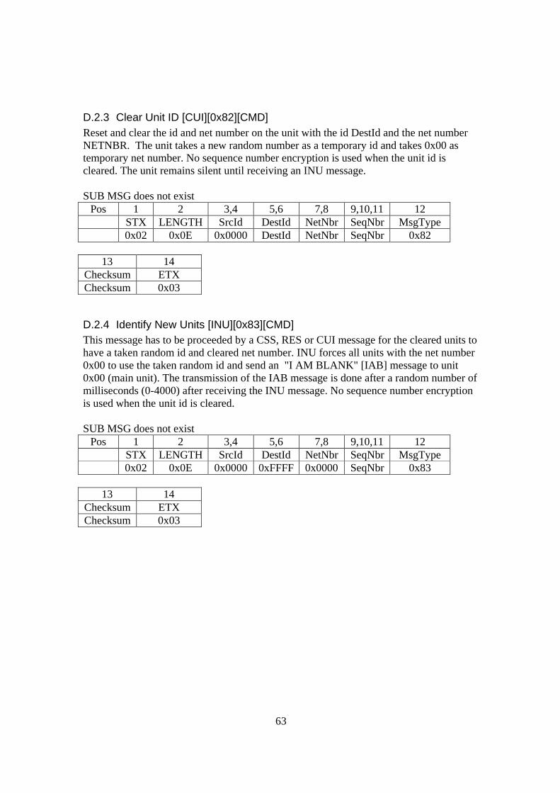
63
D.2.3 Clear Unit ID [CUI][0x82][CMD] Reset and clear the id and net number on the unit with the id DestId and the net number NETNBR. The unit takes a new random number as a temporary id and takes 0x00 as temporary net number. No sequence number encryption is used when the unit id is cleared. The unit remains silent until receiving an INU message. SUB MSG does not exist
Pos 1 2 3,4 5,6 7,8 9,10,11 12 STX LENGTH SrcId DestId NetNbr SeqNbr MsgType 0x02 0x0E 0x0000 DestId NetNbr SeqNbr 0x82
13 14
Checksum ETX Checksum 0x03
D.2.4 Identify New Units [INU][0x83][CMD] This message has to be proceeded by a CSS, RES or CUI message for the cleared units to have a taken random id and cleared net number. INU forces all units with the net number 0x00 to use the taken random id and send an "I AM BLANK" [IAB] message to unit 0x00 (main unit). The transmission of the IAB message is done after a random number of milliseconds (0-4000) after receiving the INU message. No sequence number encryption is used when the unit id is cleared. SUB MSG does not exist
Pos 1 2 3,4 5,6 7,8 9,10,11 12 STX LENGTH SrcId DestId NetNbr SeqNbr MsgType 0x02 0x0E 0x0000 0xFFFF 0x0000 SeqNbr 0x83
13 14
Checksum ETX Checksum 0x03
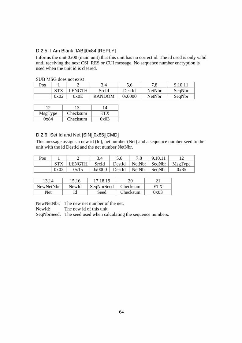
64
D.2.5 I Am Blank [IAB][0x84][REPLY] Informs the unit 0x00 (main unit) that this unit has no correct id. The id used is only valid until receiving the next CSI, RES or CUI message. No sequence number encryption is used when the unit id is cleared. SUB MSG does not exist
Pos 1 2 3,4 5,6 7,8 9,10,11 STX LENGTH SrcId DestId NetNbr SeqNbr 0x02 0x0E RANDOM 0x0000 NetNbr SeqNbr
12 13 14
MsgType Checksum ETX 0x84 Checksum 0x03
D.2.6 Set Id and Net [SIN][0x85][CMD] This message assigns a new id (Id), net number (Net) and a sequence number seed to the unit with the id DestId and the net number NetNbr.
Pos 1 2 3,4 5,6 7,8 9,10,11 12 STX LENGTH SrcId DestId NetNbr SeqNbr MsgType 0x02 0x15 0x0000 DestId NetNbr SeqNbr 0x85
13,14 15,16 17,18,19 20 21
NewNetNbr NewId SeqNbrSeed Checksum ETX Net Id Seed Checksum 0x03
NewNetNbr: The new net number of the net. NewId: The new id of this unit. SeqNbrSeed: The seed used when calculating the sequence numbers.
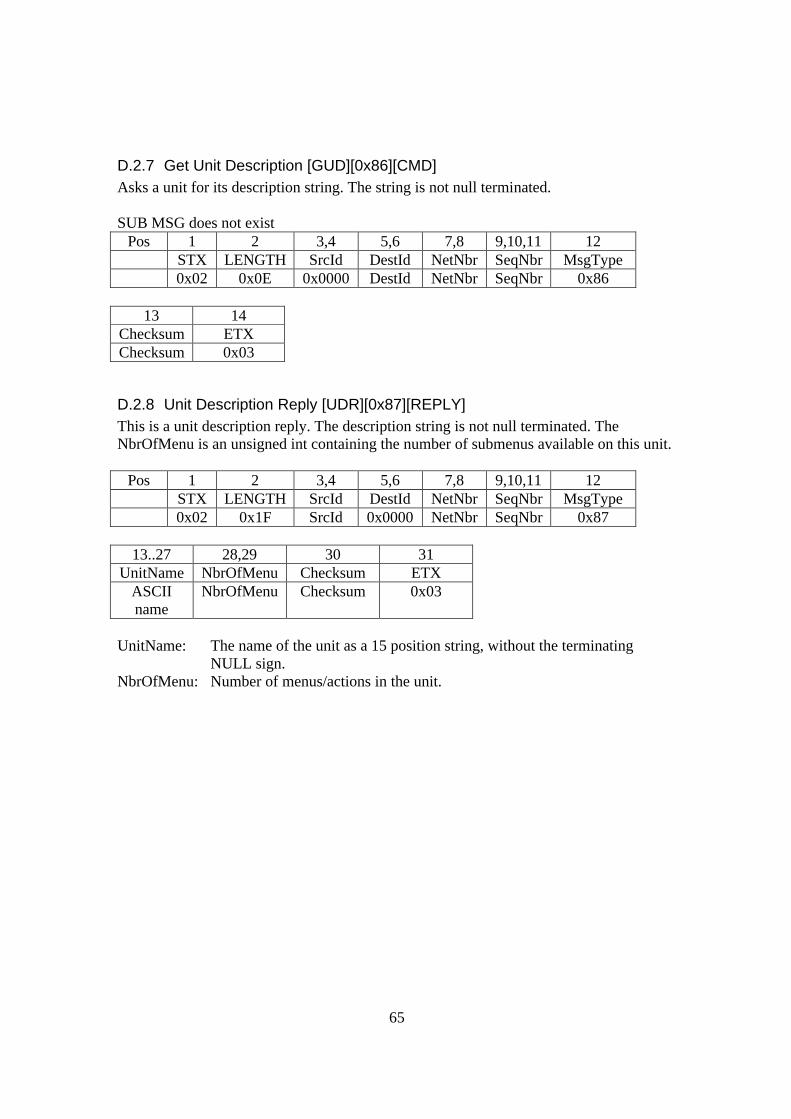
65
D.2.7 Get Unit Description [GUD][0x86][CMD] Asks a unit for its description string. The string is not null terminated. SUB MSG does not exist
Pos 1 2 3,4 5,6 7,8 9,10,11 12 STX LENGTH SrcId DestId NetNbr SeqNbr MsgType 0x02 0x0E 0x0000 DestId NetNbr SeqNbr 0x86
13 14
Checksum ETX Checksum 0x03
D.2.8 Unit Description Reply [UDR][0x87][REPLY] This is a unit description reply. The description string is not null terminated. The NbrOfMenu is an unsigned int containing the number of submenus available on this unit.
Pos 1 2 3,4 5,6 7,8 9,10,11 12 STX LENGTH SrcId DestId NetNbr SeqNbr MsgType 0x02 0x1F SrcId 0x0000 NetNbr SeqNbr 0x87
13..27 28,29 30 31
UnitName NbrOfMenu Checksum ETX ASCII name
NbrOfMenu Checksum 0x03
UnitName: The name of the unit as a 15 position string, without the terminating
NULL sign. NbrOfMenu: Number of menus/actions in the unit.

66
D.2.9 Get Menu/Action [GMA][0x88][CMD] Asks the unit with the id DestId for the menu/action with the number MANbr.
Pos 1 2 3,4 5,6 7,8 9,10,11 12 STX LENGTH SrcId DestId NetNbr SeqNbr MsgType 0x02 0x23 0x0000 DestId NetNbr SeqNbr 0x88
13,14 15 16
MANbr Checksum ETX MANbr Checksum 0x03
MANbr: The number of the requested menu/action.
D.2.10 Menu/Action Reply [MAR][0x89][REPLY] This is a menu/action reply. The description string is not null terminated. The MAId is an unsigned int containing a unique number from the device’s internal menu system.
Pos 1 2 3,4 5,6 7,8 9,10,11 12 STX LENGTH SrcId DestId NetNbr SeqNbr MsgType
0x02 0x23 SrcId 0x0000 NetNbr SeqNbr 0x89
13,14 15,16 17,18 19,33 34 35 MANbr MAId ParentId Name Checksum ETX
MANbr MAId ParentId ASCII name
Checksum 0x03
Name: This is the name of the menu/action. The name is a 15-position string,
without the terminating NULL sign.
MANbr: This is the number of the menu/action. All the menus in a device are arranged in a sorted order from 1 to the number of menus/actions in the device. The number of a specific menu/action will change if menus/actions are added to the device in run time.
MAId: The menu/action id is a unique number that corresponds to the menu/action name. This number will never be changed and is sent to the device when the action is requested. If the action/menu is a menu then nothing is done on the device.
ParentId: The parent id is the id of the parent menu. This enables an unlimited depth of the menu structure.
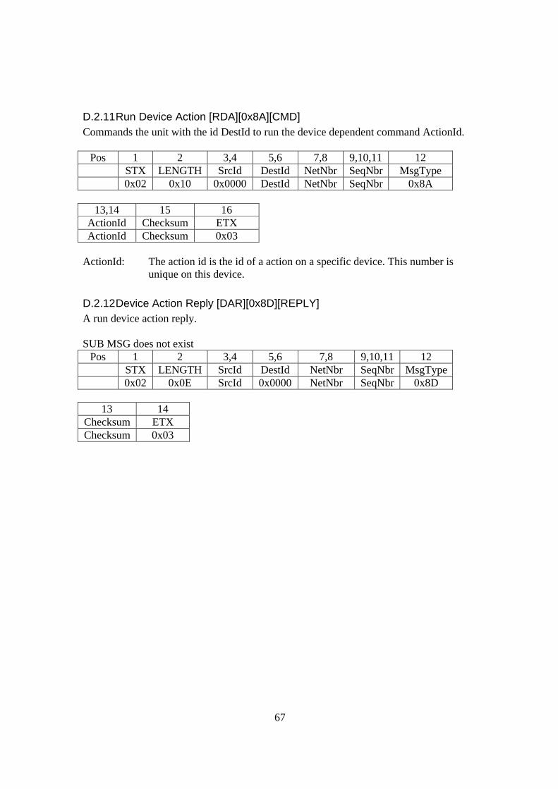
67
D.2.11 Run Device Action [RDA][0x8A][CMD] Commands the unit with the id DestId to run the device dependent command ActionId.
Pos 1 2 3,4 5,6 7,8 9,10,11 12 STX LENGTH SrcId DestId NetNbr SeqNbr MsgType 0x02 0x10 0x0000 DestId NetNbr SeqNbr 0x8A
13,14 15 16
ActionId Checksum ETX ActionId Checksum 0x03
ActionId: The action id is the id of a action on a specific device. This number is
unique on this device.
D.2.12 Device Action Reply [DAR][0x8D][REPLY] A run device action reply. SUB MSG does not exist
Pos 1 2 3,4 5,6 7,8 9,10,11 12 STX LENGTH SrcId DestId NetNbr SeqNbr MsgType 0x02 0x0E SrcId 0x0000 NetNbr SeqNbr 0x8D
13 14
Checksum ETX Checksum 0x03
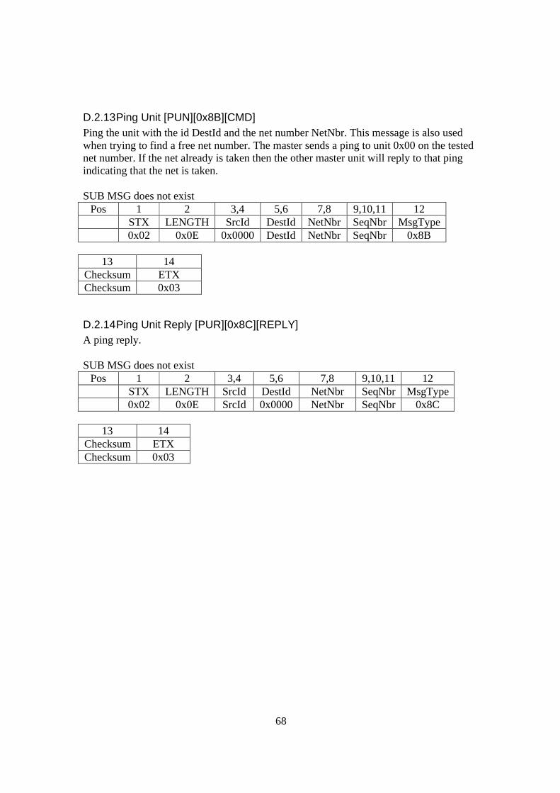
68
D.2.13 Ping Unit [PUN][0x8B][CMD] Ping the unit with the id DestId and the net number NetNbr. This message is also used when trying to find a free net number. The master sends a ping to unit 0x00 on the tested net number. If the net already is taken then the other master unit will reply to that ping indicating that the net is taken. SUB MSG does not exist
Pos 1 2 3,4 5,6 7,8 9,10,11 12 STX LENGTH SrcId DestId NetNbr SeqNbr MsgType 0x02 0x0E 0x0000 DestId NetNbr SeqNbr 0x8B
13 14
Checksum ETX Checksum 0x03
D.2.14 Ping Unit Reply [PUR][0x8C][REPLY] A ping reply. SUB MSG does not exist
Pos 1 2 3,4 5,6 7,8 9,10,11 12 STX LENGTH SrcId DestId NetNbr SeqNbr MsgType 0x02 0x0E SrcId 0x0000 NetNbr SeqNbr 0x8C
13 14
Checksum ETX Checksum 0x03
69
Appendix E - References 1 Bluetooth Homepage, http://www.bluetooth.com/, Bluetooth, 2001 2 Stanislav Korotygin, Development of Wireless Network Technologies: IEEE 802.11 Standard, http://www.digit-life.com/articles/wlan/, 2001-12-01 3 SmartHomeForum Homepage, http://www.smarthomeforum.com/, Intellicom Innovation AB, 2001-12-01 4 Doublas E. Comer, Internetworking with TCP/IP, 2000 5 X10 Transmission Theory, http://www.x10.com/support/technology1.htm, X10, 1998 6 Ed Cheung, Email: [email protected], 7 JINI homepage, http://wwws.sun.com/software/jini/ , Sun Microsystems, 2001-12-01 8 S.N.A.P Scalable Node Address Protocol document revision 1.03, http://www.hth.com/snap/, HTH, 1998-2002 9 High Tech Horizon’s homepage, http://www.hth.com/, HTH, 2001-12-01 10 HAVI Homepage, http://www.havi.org/, The HAVi Organization, 2001-12-01 11 Kenneth P. Wacks, Introduction to the LONTALK® Communication protocol, http://www.hometoys.com/htinews/oct97/articles/wacks/wacks.htm, Home Toys Inc, 1997 12 Echelon homepage, http://www.echelon.com/, Echelon Corporation, 2000 13 CEBus Users Group Homepage, http://www.cebus.org/, CEBus Industry Council, 2001-12-01 14 Universal Plug and Play Forum, http://www.upnp.org/, Microsoft Corp., 2001-12-01 15 Jeff Frohweins, Dev’rs Game Boy Advanced FAQs, http://www.devrs.com/gba/files/gbadevfaqs.php, 2001-12-01 Reiner Ziegler’s Gameboy Advance Informationpage, http://www.ziegler.desaign.de/GBA/gba.htm, 2001-12-01 Setting Up Your GBA Development Environment http://www.matt-tighe.co.uk/gba/tutorials/vstudio/vstudio.htm, Savage Development, 2001-12-01 Game Boy Advance Hardware Page, Communication Cable of GB and GBA, http://davidwu_2001.tripod.com/root/, 2001-12-01 16 ARM Evaluator-7T Board User Guide, Arm Limited , 2000 17 Redhat eCos Homepage. http://sources.redhat.com/ecos/, Red Hat Inc., 2001-12-01 eCos Reference Manual, Red Hat Inc, 1998 eCos Mailinglist. http://sources.redhat.com/ml/ecos-discuss/, 2001-12-01 Hardware supported by eCos, http://sources.redhat.com/ecos/hardware.html, Red Hat Inc, 2001-12-01 RedBoot binaries and support files, http://sources.redhat.com/ecos/boards/redbootbins/, Red Hat Inc, 2001-12-01 RedBoot™ User's Guide: Document Version 1.5m, Prev Chapter 5. Installation and Testing, http://sources.redhat.com/ecos/docs-latest/redboot/e7t.html, Red Hat Inc, July 2001 18 Red Hat Homepage, http://www.redhat.com/, Red Hat Inc., 2002-12-01 19 The uClinux Directory - Linux for ARM based machines, http://home.at/uclinux/, Alchemy Computing Ltd, 2001-11-01 20 Microchip PIC16F87X Data Sheet, Microchip Technology Inc, 1999 21 Ericsson T28 AT Command Online Reference Manual, Ericsson Mobile Communications AB, 1998 Comparison chart of AT+C commands of GSM devices, http://gatling.ikk.sztaki.hu/~kissg/gsm/at+c.html, 2002 22 Brent A. Miller/Chatschik Bisdikian, Bluetooth Revealed, 2001 23 AXIS Communications homepage, http://www.axis.com/, AXIS Communications, 2001-12-01 24 Project Info, AXIS OpenBT Stack http://sourceforge.net/projects/openbt/, 2001-12-01 AXIS OpenBT Stack homepage, http://developer.axis.com/software/bluetooth/, AXIS Communications, 2001-12-01 25 WOSP- Wireless Open Source Platform, http://www.combitechsystems.com/node2866.asp, Saab AB, 2001-12-01 26 Combitech Systems Homepage, http://www.combitechsystems.com/, Saab AB, 2001-12-01 27 Michael R. Sweet, Serial Programming Guide for POSIX Operating Systems, 5th Edition, 2nd Revision, http://www.easysw.com/~mike/serial/serial.html, 2001-12-01 28 ELFA-catalogue, ELFA AB, 2000

70
Maxim Datasheet: +5V-Powered, Multichannel RS-232 Drivers/Receivers, Maxim Integrated Products, 2001 29 Maxim Datasheet: Low-Power RS-485/RS-422 Transceivers, Maxim Integrated Products, 1996 30 Scott Howard, CrossGCC FAQ, http://www.objsw.com/CrossGCC/, 2001-12-01 31 Introduction to CVS, http://www.cvshome.org/docs/blandy.html, CollabNet Inc, 2001-11-01 32 Building the ARM development tools for Windows, http://sources.redhat.com/ecos/tools/win-arm-elf.html, Red Hat Inc, 2001-12-01 33 Maxim Datasheet: Low-Power RS-485/RS-422 Transceivers, Maxim Integrated Products, 1996