Institutionen för systemteknik - DiVA...
62
Institutionen för systemteknik Department of Electrical Engineering Examensarbete Driver Circuit for an Ultrasonic Motor Examensarbete utfört i Elektroniksystem vid Tekniska högskolan vid Linköpings universitet av Henrik Ocklind LiTH-ISY-EX–13/4659–SE 2013 TEKNSIKA HÖGSKOLAN LINKÖPINGS UNIVERSITET Department of Electrical Engineering Linköpings tekniska högskola Linköpings University Institutionen för systemteknik S-581 83 Linköping Sweden 581 83 Linköping
Transcript of Institutionen för systemteknik - DiVA...

Institutionen för systemteknikDepartment of Electrical Engineering
Examensarbete
Driver Circuit for an Ultrasonic Motor
Examensarbete utfört i Elektroniksystem vid Tekniska högskolan vidLinköpings universitet
av
Henrik Ocklind
LiTH-ISY-EX–13/4659–SE2013
TEKNSIKA HÖGSKOLANLINKÖPINGS UNIVERSITET
Department of Electrical Engineering Linköpings tekniska högskola
Linköpings University Institutionen för systemteknik
S-581 83 Linköping Sweden 581 83 Linköping


Driver Circuit for an Ultrasonic Motor
Master thesis performed in Electronics Systemsat Linköpings Institute of technology
By:
Henrik Ocklind
Supervisor: Ove GustafssonFlir Systems
Anders WistrandFlir Systems
Joakim AlvbrantES, ISY
Examiner: Oscar GustafssonES, ISY
Linköping, 2013-02-01

Abstract
To make a camera more user friendly or let it operate without an user thecamera objective needs to be able to put the camera lens in focus. Thisfunctionality requires a motor of some sort. Due to its many benefits theultrasonic motor is a preferred choice. The motor requires a driving circuitto produce the appropriate signals and this is what this thesis is about. Themain difficulty that needs to be considered is the fact that the ultrasonicmotor is highly non-linear.
This report will give a brief walk through of how the ultrasonic motor works,its pros and cons and how to control it. How the driving circuit is designedand what role the various components fills. The regulator is implementedin C-code and runs on a microprocessor while the actual signal generationis done on a CPLD (Complex programmable logic device). The report endswith a few suggestions of how to improve the system should the presentedsolution not perform at a satisfactory level.


Acknowledgements
I would like to extend my gratitude to Flir Systems for the opportunityto do this project, it has been very rewarding. Furthermore I would like tothanks my supervisors at Flir, Ove Gustafsson and Anders Wistrand, for theirsupport and help to make things run smoothly. I would also like to thankmy supervisor at ISY, Joakim Alvbrant and my examiner Oscar Gustafssonfor their valuable insights. A special thanks goes out to my objector, GustavWallin for having the patience of an angel.


Contents
1 Introduction 81.1 Background . . . . . . . . . . . . . . . . . . . . . . . . . . . . 81.2 Purpose . . . . . . . . . . . . . . . . . . . . . . . . . . . . . . 91.3 Goal . . . . . . . . . . . . . . . . . . . . . . . . . . . . . . . . 91.4 Delimitations . . . . . . . . . . . . . . . . . . . . . . . . . . . 101.5 Method . . . . . . . . . . . . . . . . . . . . . . . . . . . . . . 101.6 Devices . . . . . . . . . . . . . . . . . . . . . . . . . . . . . . 10
1.6.1 Micro Processor . . . . . . . . . . . . . . . . . . . . . . 101.6.2 Complex Programmable Logic Device . . . . . . . . . . 11
1.7 Environment . . . . . . . . . . . . . . . . . . . . . . . . . . . . 111.7.1 SDCC . . . . . . . . . . . . . . . . . . . . . . . . . . . 111.7.2 Modelsim . . . . . . . . . . . . . . . . . . . . . . . . . 121.7.3 ISE Webpack . . . . . . . . . . . . . . . . . . . . . . . 121.7.4 Matlab . . . . . . . . . . . . . . . . . . . . . . . . . . . 121.7.5 Other Tools . . . . . . . . . . . . . . . . . . . . . . . . 12
2 The Ultrasonic Motor 142.1 The Piezoelectric Effect . . . . . . . . . . . . . . . . . . . . . 142.2 The Barth Motor . . . . . . . . . . . . . . . . . . . . . . . . . 152.3 The Travelling Wave Motor . . . . . . . . . . . . . . . . . . . 16
2.3.1 Architecture . . . . . . . . . . . . . . . . . . . . . . . . 162.3.2 Operating Principle . . . . . . . . . . . . . . . . . . . . 17
2.4 Advantages of the Ultrasonic Motor . . . . . . . . . . . . . . . 182.4.1 No Influence of Magnetic Fields . . . . . . . . . . . . . 182.4.2 Driving Properties . . . . . . . . . . . . . . . . . . . . 182.4.3 Structural Properties . . . . . . . . . . . . . . . . . . . 18
2.5 Disadvantages of the Ultrasonic Motor . . . . . . . . . . . . . 192.5.1 Friction . . . . . . . . . . . . . . . . . . . . . . . . . . 192.5.2 Non-Linear . . . . . . . . . . . . . . . . . . . . . . . . 19
2

3 The System 203.1 Overview . . . . . . . . . . . . . . . . . . . . . . . . . . . . . . 203.2 Circuit Design . . . . . . . . . . . . . . . . . . . . . . . . . . . 21
3.2.1 Microprocessor . . . . . . . . . . . . . . . . . . . . . . 213.2.2 Complex Programmable Logic Device . . . . . . . . . . 223.2.3 The Inverter Stage . . . . . . . . . . . . . . . . . . . . 23
4 Driving the Motors 264.1 Speed Characteristics . . . . . . . . . . . . . . . . . . . . . . . 264.2 Motor Diameter and Performance . . . . . . . . . . . . . . . . 28
4.2.1 Torque . . . . . . . . . . . . . . . . . . . . . . . . . . . 284.2.2 Speed . . . . . . . . . . . . . . . . . . . . . . . . . . . 284.2.3 Output Power . . . . . . . . . . . . . . . . . . . . . . . 28
4.3 A Comparison of the Two Motors . . . . . . . . . . . . . . . . 294.3.1 Frequency . . . . . . . . . . . . . . . . . . . . . . . . . 304.3.2 Speed and Frequency . . . . . . . . . . . . . . . . . . . 304.3.3 Torque and Efficiency . . . . . . . . . . . . . . . . . . . 324.3.4 Mechanical Differences . . . . . . . . . . . . . . . . . . 32
4.4 Changes in the Circuit . . . . . . . . . . . . . . . . . . . . . . 334.5 End of Applied Study . . . . . . . . . . . . . . . . . . . . . . . 34
5 The Regulator 365.1 PID Controller . . . . . . . . . . . . . . . . . . . . . . . . . . 36
5.1.1 Proportional Regulating . . . . . . . . . . . . . . . . . 375.1.2 Integral Regulating . . . . . . . . . . . . . . . . . . . . 375.1.3 Derivative Regulating . . . . . . . . . . . . . . . . . . . 375.1.4 The whole regulator . . . . . . . . . . . . . . . . . . . 38
5.2 Tuning the System . . . . . . . . . . . . . . . . . . . . . . . . 385.2.1 Ziegler-Nichols Method . . . . . . . . . . . . . . . . . . 385.2.2 Manual Tuning . . . . . . . . . . . . . . . . . . . . . . 39
5.3 The Model . . . . . . . . . . . . . . . . . . . . . . . . . . . . . 395.4 Regulating the Motor . . . . . . . . . . . . . . . . . . . . . . . 405.5 Poles and Phase Margin . . . . . . . . . . . . . . . . . . . . . 43
6 Improvements 466.1 Evaluation of the Current Circuit . . . . . . . . . . . . . . . . 46
6.1.1 Clock Doubler . . . . . . . . . . . . . . . . . . . . . . . 476.1.2 Double Counter . . . . . . . . . . . . . . . . . . . . . . 486.1.3 Results . . . . . . . . . . . . . . . . . . . . . . . . . . . 49
6.2 Ideas for the Regulator . . . . . . . . . . . . . . . . . . . . . . 496.2.1 Derivative Term . . . . . . . . . . . . . . . . . . . . . . 50
3

6.2.2 Limiting the Error . . . . . . . . . . . . . . . . . . . . 50
7 Conclusion 52
4


Acronyms
ADC Analog to digital converterCPLD Complex programmable logic deviceDAC Digital to analog converterFPC Flexible printed circuitHT65 High torque, 65 mm, the larger motorHz Hertz, SI unit for frequencyI2C Inter-integrated circuit, a serial bus developed by PhilipsMCU Microcontroller, a simple processor with extra featuresP12 Pencil, 12 mm, the smaller motorPID Proportional-integral-derivative, a type of regulatorUSM Ultrasonic motorT Tesla, SI unit for magnetic flux densityTilo Combinatorial logic delayVrms Voltage root mean square, for a sine wave the peak voltage divided by
√2
6


Chapter 1
Introduction
This chapter presents the background, purpose, goals and delimitations ofthe thesis along with the method and necessary tools.
1.1 BackgroundThis thesis project was performed at Flir Systems. Flir is a company thatworks with thermal imaging and more specifically they design and manufac-ture infrared cameras. A lens made out of germanium will look solid blackto the human eye, but to infrared light the lens is transparent. Howeverthe rules of optics still apply so the lens needs to be in focus to get a clearimage. One way of doing that would be to let the user manually tune thelens position, but this is time consuming and not always a practical solutionsince some of the cameras made at Flir need to operate on its own or needto be controlled remotely, for example in surveillance scenarios. That is whythe camera objective usually has a built in autofocusing system which is adriving circuit paired with a regulator. The purpose of this system is to placethe lens at the appropriate position by controlling a motor that is connectedto the lens. In this case the motor used is an ultrasonic motor. These motorsare very popular for this kind of application because they are ring shapedand thus fit very well into the design since most camera objectives are cylin-drical. Other advantages include low noise, quick response and the fact thatit is a more durable solution compared to a regular electrical motor.
8

1.2 PurposeUltrasonic motors comes in different shapes and sizes as well as with differentproperties. The company that makes the motors do not sell the associatedelectronic driver circuits so it is up to customer to create their own. Theproject presented in this report is a continuation of a previous project wherea driver circuit was developed for a motor with a diameter of 65 mm. Fukokuis the company that made this motor and they also manufacture a motorwith a diameter of 12 mm. The smaller motor has a number of advantages,for example, it requires less space (which can be seen in figure 1.1), weighsless, has a lower power consumption and is cheaper. In theory it should bepossible to modify the existing circuit board for the larger motor to controlthe smaller one. However, the motors works in different frequency ranges, hasdifferent properties and ultrasonic motors (USM) suffers from non-linearities.This project will find out if it is possible and how it is done.
Figure 1.1: Stators for the big and small motors.
1.3 GoalThe goal of this thesis is to develop a driving circuit for a 12 mm ultrasonicmotor that performs on the same level regarding speed and response timeas the circuit for the bigger motor. What this means is that new code forthe microprocessor and the complex programmable logic device (CPLD) willbe developed, specifically the code that regulates the system. Furthermorethere will be a theoretic study into possible improvements in the architectureof the circuit board.
9

1.4 DelimitationsThe circuit board is already made and the overall architecture will not bealtered, thus the components are predetermined. The microprocessor isa Texas Instruments MSC1202Y2 which has a built in analogue to digi-tal converter(ADC), it belongs to the 8051 family. The CPLD is a XilinxXCR3064XL, which has 64 macro cells. The whole circuit is synchronised bya crystal oscillator which oscillates at 40 MHz, this clock will be referred toas the system clock.
1.5 MethodThe first phase of this project will be to get a basic understanding of how theultrasonic motor works. This will be followed by an analysis of the previousproject, in essence that means that all the written code (C++, assemblerand VHDL) and all the components in the circuit will be scrutinized andanalysed. There is no existing coding environment so as a part of the projectthe necessary programming tools needs to be selected and then implementedinto the environment. These tools will be described later in this chapter. Toverify the code an I2C-communication between a computer and the circuitneeds to be established. Most of the work concerning the regulator will bedone through simulations in Matlabs Simulink.
1.6 DevicesThis section gives a short explanation of the microprocessor and the CPLD.
1.6.1 Micro ProcessorTexas Instrument MSC1202Y2 is the processor used in the circuit, it has abuilt in ADC/DAC and a 4 kB flash memory The processor core is basedon the 8051 architecture which was developed by Intel in the early 1980s.However, the processor used in this thesis is an improved version, it doesaccept the same instruction set, but it processes data approximately threetimes faster [1]. The 8051-architecture is a widely used standard and becauseof this there exists a large number of different compilers and the generatedcode can be downloaded to any 8051-controller if needed. Some propertiesworth mentioning for the controller includes the 8 bit CPU, 8 bit data busand the 16 bit address bus [2] and the general core can be seen in figure 1.2.
10

Figure 1.2: The standard 8051 core.
Probably the most defining feature of this chip is the ADC and it is arather central part of this project, more on this later. The ADC utilizes aSigma delta converter with a 16 bit resolution.
1.6.2 Complex Programmable Logic DeviceXilinx XCR3064XL is the CPLD chip used. A CPLD unlike a FPGA does notrequire an external configuration memory to boot and is therefore suitablefor this type of circuit. VHDL is the chosen language for programming theCPLD.
1.7 EnvironmentThis section will list the various programs and tools needed to for implemen-tation, simulations and validation.
1.7.1 SDCCSDCC is an abbreviation for Small device C compiler and as the name im-plies it is an ANSI C compiler and includes other functionalities as linker,assembler, debugger and simulator [3]. It is an open source project and isdistributed under the GNU general public license. It is possible to use witha wide variety of processors including processors of the 8051 architecture.
11

1.7.2 ModelsimUsed to debug and simulate VHDL code before it is downloaded to the CPLD.
1.7.3 ISE WebpackISE Webpack is a free of charge program developed by Xilinx. It is used tosynthesize and download code to the CPLD.
1.7.4 MatlabThe regulator will be tested and verified in Matlab before it is implementedin the actual system.
1.7.5 Other ToolsIn addition to previously mentioned tools there are some other required toolswhich have no need to be described in detail. Those include an oscilloscope, avoltage meter, some circuits developed by Flir to program the microprocessorand the CPLD and also equipment needed to communicate with the drivingcircuit through I2C.
12


Chapter 2
The Ultrasonic Motor
This chapter will explain how the ultrasonic motor (USM) works and how itdiffers from a regular electromagnetic motor.
2.1 The Piezoelectric EffectTo get a grasp of how the USM works the principle of the piezoelectric effectneeds to be understood. The discovery of piezoelectricity is attributed tothe Curie brothers who made the discovery in the late 19th century whilestudying Rochelle salt [5]. Piezo is Greek and translates into pressure so inpure English the effect would be called pressure-electric. There are a numberof materials that exhibit piezoelectric properties, but they all work the same.If pressure is applied to the material, or more specifically if the material isdeformed, an electric field is generated and thus an electric potential. Forthis project the opposite is desired and since the effect is reversible that canbe achieved. An electric field with a positive potential will make the materialexpand, this is illustrated in figure 2.1. The short version of the piezoelectriceffect would be that it describes a material that can convert mechanical toelectrical energy and vice versa.
14

Figure 2.1: How an applied voltage affects the piezoelectric material.
2.2 The Barth MotorThe human ear can detect sound waves ranging from 20 Hz to 20 kHz whichis commonly known as the audible frequency range. Signals with a higherfrequency operates in the ultrasonic region and those kind of signals arerather easy to create using a piezoelectric vibrator of some sort. It has beenknown for some time that the energy density of such a vibrator is higher thanthat of an electromagnetic motor, up to ten times higher [4]. However therewould be a while before anyone attempted to construct a motor using thepiezoelectric principle. In 1973 H.V. Barth published his work on an USM, it
m
Figure 2.2: H.V. Barth’s motor
consisted of one rotor and two vibrators. It is a fairly straight forward design,when the left vibrator is excited the rotor moves clockwise and in the oppositedirection when the right vibrator is excited [4], a model is illustrated in figure2.2. Since then many different motors have been developed, including thewedge-type, the twist coil, various linear motor designs and also the motorused in this project, the travelling wave motor.
15

2.3 The Travelling Wave MotorThe travelling wave motor was developed by Toshiiku Sashida in 1982. Thereare some variations of this type of motor and the one used in this project isof ring type.
2.3.1 ArchitectureThe overall architecture of this motor is pretty similar to an ordinary elec-tromagnetic motor. It consists of two main parts, the stator and the rotor.The stator is stationary in the sense that it does not move along the rotationaxis (cylindrical coordinates), it does however move up and down, but moreon that in the next section. The stator is made by combining two parts, thepiezoelectric part and on top of that an elastic body which is recognisableby its saw tooth silhouette.
Figure 2.3: Left: The different parts of the USM. Right: A motor, the statoris clearly visible.
The rotor is the moving part of the motor, the spring pushes the statorand rotor assembly together and the oscillations in the piezoelectric materialcauses the rotor the rotate, hence the name. In an ordinary electromagneticmotor the rotor is not in physical contact with the stator, however the driv-ing principle of the USM depends on friction between the stator and rotor.Therefore a thin lining is applied to the rotor to increase friction and thusdecrease sliding energy loss. Also the lining increases the durability of themotor. Thus forming the rotor assembly.
For the motor to work the rotor and stator needs to be pressed together
16

and that is why there is a spring in the bottom. Then there are a numberof plates to equalize pressure in the design and some protective sheets toprotect against wear and tear. What the motor looks like under the hood isillustrated in figure 2.3.
2.3.2 Operating PrincipleThe piezoelectric material is connected to a two-phase sinusoidal voltage witha 90 degree phase shift, in other words a sine and a cosine phase. The un-shifted voltage will be called phase A and the other one phase B henceforth.As described in figure 2.4 there are alternating nodes with different polar-ization spread out around the ring, when a positive voltage is applied to anode it will cause positive nodes to expand and negative nodes to shrink, theopposite is true for a negative voltage.
If only one phase is active a standing wave will be created, even though thevoltage is only applied to a little less than half of the ring the wave willpropagate through the entire ring. When the other phase is activated thewave will move which is called a travelling wave. Imagine a fixed point onthe surface of the piezoelectric disc, this point will move up and down inan elliptical trajectory which is illustrated to the right in figure 2.4. Thereare two main stages to convert the electrical energy to mechanical ditto. Inthe first stage the piezoelectric electrodes becomes excited which causes vi-brations in the material, in the later stage these vibrations are transmittedthrough to the rotor which, given enough pressure, will move the rotor in theopposite direction of the travelling wave.
Figure 2.4: Left: Piezoelectric disc. Right: Driving principle of an USM.
17

2.4 Advantages of the Ultrasonic MotorThis section will explain the various advantages of the USM.
2.4.1 No Influence of Magnetic FieldsThis is perhaps one of the most important aspects of the USM since anelectromagnetic motor may not function properly while under the influenceof a magnetic field. The principle of electromagnetic induction states that afluctuation in the magnetic field will create an electric field and the USM isno exception, however the effects are negligible. Assume a 1 T fluctuation inthe magnetic flux density at about 60 Hz, this will create an electric field ofabout 100 V m−1 which is 100 times lower than the normal field strength ofthe piezoelectric material [4]. Since the motor does not utilize a magnet nora coil it will not generate magnetic fields either.
2.4.2 Driving PropertiesSince the motor operates at a frequency range above the audible range themotor is very quiet. Compared to an electromagnetic motor the USM hasconsiderable higher torque, a factor of somewhere between 10 and 100 com-pared to a electromagnetic motor of a similar size [6]. The difference is largestat low speeds. Moreover the drive does not need any gears and because ofthis and the low inertia of the rotor the motor has a very quick response forboth start and stop (about 1 ms [4]). As soon as the ceramic starts to vibratethe rotor will start moving and the moment it stops the stator will work asa brake. This makes the motor easy to control and suitable for machineswhere high precision is needed.
2.4.3 Structural PropertiesThe motor is ring shaped and thus hollow, this makes the motor easy to fitin your design. Furthermore the USM is very light The structure is rathersimple and therefore easy to manufacture.
18

2.5 Disadvantages of the Ultrasonic MotorBesides the listed advantages in section 2.4 the USM has its drawbacks.
2.5.1 FrictionThe rotor is pressed down onto the stator and it is the friction between thesetwo parts that makes the motor work. However, this also generates a lot ofheat. The motor is therefore not suitable for a continuous workload since thetemperature would rise to extreme levels.
2.5.2 Non-LinearIt is hard to derive a mathematical model of the motor. This is due to thefact that the motor parameters are hard to obtain. To complicate mattersfurther the values changes over time. As mentioned above the motor gen-erates a lot of heat while running and the change in temperature will effectthe performance of the motor. Furthermore the travelling wave can only beconsidered ideal at the resonance frequency (more on this in chapter 4), thefarther the driving frequency strides from resonance the harder it is to pre-dict the motors behaviour. Finally the speed of the motor depends on theinput frequency, however the relation is not linear.[6]
19

Chapter 3
The System
This chapter will give a description of the driver circuit developed in theprevious project.
3.1 OverviewTo get an understanding of the circuit the first thing that needs to be doneis to figure out what its role is in the system. The whole system can commu-nicate through a I2C-bus, other signals include inputs to the circuit, currentposition and wanted position. The output consists of the signals needed tocontrol the motor. In between the circuit converts the input signals to aformat that makes sense, put the signals through a regulating algorithm andfinally outputs a sinusoidal waveform.
Since the driving circuit is the last step before the motor and the only partof the system that communicates directly with the USM, the circuit is placedaround the camera objective on top of the motor. This also means that thecircuit board is shaped like a ring. Its position relative to the camera can beseen in figure 3.1.
20

Figure 3.1: A somewhat complete camera, the circuit is clearly visible aroundthe lens.
3.2 Circuit DesignThis section will describe the three main parts of the system. Also presentin the design are a temperature indicator, electrostatic discharge protectionand a crystal oscillator that oscillates at 40 MHz and is the clock for theCPLD.
Figure 3.2: The main blocks in the design.
3.2.1 MicroprocessorAs in most embedded systems the microprocessor is responsible for most ofthe computations in the system. In this case the MCU has a built in ADCwhich comes in handy since the current position (labelled Pos in figure 3.2)
21

is an analogue signal. The signal is generated by a potentiometer that isphysically attached to the lens and thus will change value when the lensmoves. The signal is then converted to a discrete number and sent to theregulator. The regulator in question is a traditional PID-regulator. Theregulator computes in which direction the motor needs to spin and how fast,this is done by outputting a six bit number to the CPLD. This number tellsthe CPLD at what frequency to run the motor, this is explained more insection 3.2.2 This means that the speed of the motor, measured in Hz, canonly be one of 64 (26) predetermined values. So using a lookup table thecomputed value is rounded to the nearest value.
The I2C-bus makes it possible for a user to communicate with the circuitwhile the system is running. The bus makes it possible to manually set thelens position or the running speed of the motor, it is also possible to changethe regulator’s coefficients, in essence the proportional (P), integral (I) andderivative (D) coefficients.
3.2.2 Complex Programmable Logic DeviceThe CPLD block is basically a state machine with four states. When thesystem is running and the wanted position does not equal the current posi-tion the CPLD loops through the states and each state means that one offour output channels is set to logical one. The system clock runs at 40 MHz,this means that one clock pulse has a time period of 25 ns. An easy wayof creating a square wave generator is to let the output signal be high for apredetermined number of clock pulses. Let the square wave be logical one for284 clock pulses and with 25% duty the that corresponds to a square wavethat runs at approximately 35 kHz. Add the six bit number from the MCUand the output signal can range from 28 kHz to 35 kHz which is suitable forthe 65 mm motor. The output frequency can be expressed as a function ofthis 6-bit number:
fout(n) = 1(284+n)∗4∗25∗10−9 , {n = 0, 1, 2, 3, ..., 63}
Figure 3.3 shows the output patterns generated from the CPLD while run-ning, why this particular pattern is desired is covered in the next section. Itis also worth noting that if you reverse the order in which the signals goeshigh, the motor will spin the other way.
22

Figure 3.3: Output signals from the CPLD while running.
3.2.3 The Inverter StageThe CPLD will generate a digital signal, however the motor needs a analoguesignal to run. That is why there needs to be an inverter stage. There aretwo identical inverters working in parallel where one generates phase A andthe other phase B.
The outputs from the CPLD are connected to the gate of a NMOS transistor,in essence the transistor works as an ordinary switch. When the signal at thegate is high the transistor is open and current flows through it. These drain ofthese transistors are wired each respective end of a transformer with a middletap where the circuits power supply is connected. Consider the schematicsin figure 3.4, when channel 1 is logical one it will make current flow upwardsthrough the transformer and onwards through transistor N1. This will createan amplified square wave in the right side of the transformer according tothe laws of inductance. When channel 2 is logical one the current will flowdownwards instead creating a negative square wave. The output can be seenin figure 3.5.
23

Figure 3.4: The schematics of the inverter stage.
The outputs from the transformers are starting to resemble a sinusoidalwaveform and it will be more apparent once the motor is connected. As itturns out the motor has a clear capacitive behaviour and will thus work asa capacitive load, effectively creating a LC-filter. As mentioned in section2.4.2 it is hard to pin point an exact value of this capacitance and it willchange overtime. However the closer the wave is to the resonance frequencythe more sinusoidal the inputs to the motor will become. Luckily the motordoes not require a perfect wave to run and with this set up the LC-filter isgood enough to provide a valid signal for all the relevant frequencies.
24

Figure 3.5: Inducted voltages at the secondary coil.
25

Chapter 4
Driving the Motors
This chapter will cover how the input frequency correlates with the speed ofthe motor and as well similarities and differences between the two motors.Furthermore it will also discuss the changes needed in the circuit design.
4.1 Speed Characteristics
Figure 4.1: Rotor speed versus drive frequency, fr marks the resonance fre-quency.
A typical frequency response of a non-specified USM is shown in figure4.1. In other words, the graph will look like this no matter the propertiesof the motor. However the exact numeric values will be unique for everytype of motor and to some degree even every individual motor. To get someperspective, the range of input frequencies that will make the motor spinallows 4f to range from somewhere between 2 to 6 kHz depending on thespecific motor. The resonance frequency can be at just the edge of the audiblesound (20 kHz) up to 5 MHz.
26

The speed of the motor is proportional to the amplitude of the vibrationsin the piezoelectric material. As mentioned in section 2.4.2 the generatedfriction heat will affect the amplitude of these vibrations causing a drop offin speed, it may be as much as 20%. To complicate matters further not onlydo the speed decrease the resonance frequency (fr) will change as well, it maydecrease by as much as 400 Hz [7]. Temperature will not decrease speed withan equal amount over the whole frequency spectra, it will have a differenteffect on each frequency level. Below is a rough illustration of how the risein temperature due to friction decreases the speed, the data was presented inthe Journal of power electronics [8]. The measurements have been performedon a USM with a resonance frequency of around 40 KHz.
Figure 4.2: How temperature affect the output speed.
One further thing worth noting is that the load torque will also affect thesystem. Load torque is the minimum amount of force the motor needs toapply to the system to keep it stable. For example, imagine a motor in a cranethat lifts some kind of weight, the load torque is the force required to keepthe weight in place. If the load torque is increased the internal impedanceof the motor will increase and thus the input voltage needs to be increasedin order to make the system perform at the same level. The speed of themotor will naturally decrease since the amount of work the motor has to dohas increased. This is however fairly linear, so it is possible to predict theoutcome beforehand with some accuracy. Since the required force to movethe camera objective is fairly predictable the load torque is constant for thispurpose.
27

4.2 Motor Diameter and PerformanceThis section will explain how the diameter of the ring motor affects theperformance. Figure 4.3 gives a graphic presentation of the results here.
4.2.1 TorqueThe torque when the motor starts up is roughly some constant multipliedwith the diameter cubed. It can be assumed that the rated torque or inother words the running torque is the starting torque times a constant. Sothe torque is proportional to the diameter cubed [4].
Torque ∝ (Diameter)3
4.2.2 SpeedThe speed is measured in revolutions per minutes (RPM). When there is noload attached to the motor the speed is approximately inversely proportionalto the diameter. As in the previous section it is assumed that speed changesdue to different loads are the no-load speed times a constant. Hence thespeed is inversely proportional to the diameter.[4]
Speed ∝ 1Diameter
4.2.3 Output PowerThe output power of an electrical motor is the product of the motors torqueand the angular speed. Given the results from the two previous sections theoutput power in relation to the diameter of the motor will not be to difficultto derive. The output power is proportional to the diameter squared. Themaximum output power is obtained at half the no-load speed since the motoris most efficient then. Due to sliding and deformation the output powerdecreases after this.
Output Power ∝ Diameter2
28

Figure 4.3: The diameter of the motor and how it effects performance.
4.3 A Comparison of the Two MotorsThis section will examine how the two motors differs. Both motors are man-ufactured by the Fukoku company. The larger motor bears the name Hightorque 65 and will be referred to as HT65 in the following text, the othermotor is the Pencil 12 and will be labelled P12.
Specification HT65 P12Diameter [mm] 65 12Weight [g] 27 5Resonance frequency [KHz] :31 :59Driving voltage [Vrms] 30 70Power consumption [W] ≤ 1 ≤ 1.2Idling speed [rpm] ≥ 65 ≥ 500Rated speed [rpm] ≥ 60 ≥ 400Max torque [gcm] ≥ 800 ≥ 50Efficiency [%] ≥ 20 ≥ 10
Table 4.1: Some notable specifications for the two motors
29

4.3.1 FrequencyIf the nodes in the piezoelectric material is placed with the same interval fora smaller and a larger ring it falls naturally that the resonance frequencywill increase since the wavelength will decrease. The frequency range willalso increase if the stator thickness increases and since HT65 has a statorthickness of 7 mm compared to the P12 which is 12 mm across the steep riseof the resonance frequency is mitigated somewhat. In the end the value ofP12 is approximately double that of the HT65, this means that the CPLDneeds to work at double the speed compared to the original circuit. Thisis not a problem per se, however it is an obstacle to overcome, especiallyconcerning the system clock. More on that in chapter 5.
4.3.2 Speed and FrequencyOn the next page there are two graphs of motor speed and how it relatesto input frequency. Figure 4.1 showed a graph for a general motor, for thepurpose of this thesis the left side of the resonance frequency is not interest-ing. This is due to the fact that it is much harder to control the motor witha regulator that works in that area. It has also been previously mentionedthat the resonance frequency is rather fickle and is prone to change whilerunning. Therefore it is advisable to only use frequencies 500 Hz or moreover the specified resonance frequency for your control algorithm. The motoris fast enough without running it at maximum speed and the drawback ofhaving a situation arise where the regulator think it is increasing the speedwhile it is in fact decreasing it makes it an unnecessary risk. Worth notingabout the graphs is that the one for HT65 was supplied by the manufacturerand the one for P12 is measurements made during this project. Some imme-diate observations include the faster speed of P12 and that its active rangeis about twice as large as for the HT65. The measurements where performedwith a minor load of a small metallic screw.
30

Figure 4.4: RPM vs. frequency, measurements of P12.
Figure 4.5: RPM vs. frequency, supplied by the manufacturer (HT65).
31

4.3.3 Torque and EfficiencyA look at table 4.1 shows that the torque is considerable smaller for P12 andwhile this is a fact it does not have that large impact on the system. TheP12 has enough torque to move the camera lens however it will reduce thespeed of the motor by a larger fraction than for the HT65.
The power consumption is larger for the smaller motor and according tofigure 4.3 the output power is smaller. It follows that the power efficiencywill be worse than for the larger motor. Since the camera for which thisproject is aimed at is a handheld device this is possible the biggest drawbackwith P12.
4.3.4 Mechanical DifferencesThe P12 is lighter and smaller and while this looks good on paper the sizeof the motor causes a mismatch in regards to the size of the motor and thesize of the camera lens. The HT65 is roughly the same size as the cameralens and so they are assembled directly to each other. The P12 needs somesort of mechanical help. While the HT65 is clearly a ring structure the P12looks more like a disc at a first glance. There is a little hole though where ascrew can be fitted, this screw can be fastened directly to the camera lens orit could be connected to a cog wheel, essentially creating a gear.
In the case without gears the inertia of the camera lens would be greaterthan that of the motors rotor, this will reduce the motors acceleration andretardation. In the other case where a gear is placed between the motorand the camera lens it will reduce the overall speed of the system, but willmaximize the possible torque[4]. The latter case is preferred here since thesystem will become quicker and stronger and that is more valuable than purespeed. There is however another drawback with this design and that is space,a gear will need more space which will force the motor to be placed outsidethe ring and the camera objective.
32

Figure 4.6: A possible gear solution.
4.4 Changes in the CircuitThe driving voltage for the P12 is more than twice the amount of the requiredvoltage for HT65. This means that the transformers in the circuit will needto be replaced by new ones with a larger ratio between the number of turnson each coil. If for some reason it is desired to use the same circuit to drivea number of different motors the new transformers will not stand in the way.A higher Vrms will make the larger motor go faster, since the expansions andcontractions in the piezoelectric material will be stronger. So this will needto be adjusted for, otherwise this is not a problem.
There is a small difference when it comes to the FPC. P12 has the threenormal inputs, phase A, phase B and ground, the same is true for HT65.HT65 has one additional output as well, a feedback node which is used todetermine the speed of the rotor. This node is not connected in the originaldesign though so it will not make this project any harder. However the threeinputs are not in the same order on the two motors which means that somerewiring is required.
Changes and additions in the VHDL- and C-code and the electronic designwill be discussed in later chapters.
33

Figure 4.7: The circuit board after the necessary changes.
4.5 End of Applied StudyDue to some restructuring at Flir Systems there has been a lack of necessaryequipment and material to finish the thesis as it was originally intended. Ev-erything so far has been tested on a real camera objective and works well,the motor can spin in either direction and the circuit board can communi-cate with the camera system. However, it has not been possible to test theregulator while downloaded into the microprocessor and thus the rest of thisreport is based on simulations and a theoretic study.
34


Chapter 5
The Regulator
At this point it is possible to drive the motor in both directions and at somepredetermined frequencies. Since the aim of the project is to develop a circuitthat can put the lens in focus without human intervention there needs to bea regulator. This chapter will give a brief explanation of the PID controllerand how it was implemented.
5.1 PID ControllerPID stands for proportional, integral and derivative and is a common wayto regulate a system. One does not need to have complete knowledge aboutthe underlying system to create a working PID controller and that is one ofits strengths. Even if it is not possible to measure noise affecting the systemthe controller will handle it since there is a feedback loop. The three parts ofthe PID controller are more or less independent and it is possible to create aworking regulator with only one or two parts, in some cases it is even desired.
Figure 5.1: A general PID controller.
36

5.1.1 Proportional Regulatingu(t) is the desired output signal and y(t) is the actual one, subtract thosetwo signals and you get the current error signal e(t). Proportional regulatingsimply means that the error signal is amplified by a constantKp (or reduced).This is the most commonly used feedback controller and have been aroundsince ancient times [9]. For the application of this thesis this part of theregulator means that the farther away the lens is from the target positionthe faster the motor spins. This type of regulating requires a non zero errorand thus the term P0 is introduced. The proportional part is given by:
Pout = Kpe(t) + P0
5.1.2 Integral RegulatingBy just using proportional regulating it is not possible to completely elimi-nate noise or disturbance. The integral term is the sum of the past errors.For the purpose of this thesis it calculates how much closer the lens is to thetarget point now than it was in the beginning, compares that with how muchdistance left and adjusts speed accordingly. The integral term speeds up thesystem, but there are some dangers. Set the Ki value too high and there is arisk that the regulator will overshoot its target, that is not necessarily a badthing, but if the overshoots becomes bigger and bigger that means trouble.Overuse of past values will as a rule lead to instability [9]. Its greatest con-tribution is that it eliminates the steady state error, or the error when theregulator has made its target. The integral term is given by:
Iout = Ki
∫ t0e(t) dt.
5.1.3 Derivative RegulatingRelying too much on measured values can lead to instability, that is whya derivative term is introduced. This term gives the regulator a chance topredict future errors and therefore it can adjust for those errors before theyhappen. What happens is that this term slows down the rate of change andtries to decrease or eliminate overcompensating of the system. This term canalso cause instability, since the term is derivative it is sensitive to transientscaused by noise. This term is given by:
Dout = Kdddte(t)
37

If the proportional part is added the following terms are obtained throughTaylor series [9]:
x(t) = Kpe(t) +Kdddte(t) ≈ Kpe(t+ τD)
τD = Kd
Kp
Where τD is how far the system can plan ahead.
5.1.4 The whole regulatorFigure 5.1 and the previous sections gives the following expression for thewhole regulator:
x(t) = Kpe(t) +Ki
∫ t0e(t) dt.+Kd
ddte(t)
5.2 Tuning the SystemThe ground rules are now established, but we still need some way to de-termine the values of Kp, Ki and Kd. A good start is the Ziegler-Nicholsmethod.
5.2.1 Ziegler-Nichols MethodThe Ziegler-Nichols method was developed by John G. Ziegler and NathanielB. Nichols and was published in their book Optimum settings for automatedcontrollers from 1942. To determine appropriate values for the PID con-trollers coefficients begin by disconnecting the integral and derivative terms,in essence setting Ki and Kd to zero. Now by set the value of Kp on the edgeof a stability or in other words make the signal oscillate at a constant am-plitude around its target value. Note which value was obtained, in the tabledenoted as Ku, and what the time period of the oscillation was, denoted Tu.There is no guarantee that this will produce a good regulator, but in mostcases it will be a good starting point. At least one of the proposed set ofvalues will. [9]
Regulator Kp Ki Kd
Normal PID 3Ku
56Ku
5Tu
3KuTu
40Some overshoot Ku
36Ku
5Tu
KuTu
5No overshoot Ku
56Ku
5Tu
KuTu
5
Table 5.1: Ziegler-Nichols coefficients for a few PID controllers
38

5.2.2 Manual TuningChances are that the solution provided by Ziegler-Nichols is not perfect sosome tuning will be required. So below is a list of all the coefficients and howan increase in the coefficients value will affect the system.
Coefficient Rise time Overshoot Settling timeKp Decrease Increase Small increaseKi Decrease Increase IncreaseKd Minor increase Decrease DecreaseCoefficient Steady state error StabilityKp Decrease DegradeKi Eliminate DegradeKd No effect Improve (if Kd is small)
Table 5.2: How an increase in a coefficients value will affect the system
5.3 The ModelThe system was simulated in Simulink. However, to do that a model ofthe system needs to be created. The model in itself is rather simple, just alookup table that outputs a certain speed given a certain frequency basedon figure 4.4. There are some complications however, since the regulator isimplemented on the MCU that regulator can not be continuously runningsince the processor has other tasks that also needs be taken care of. Thismeans that the regulator needs to function in the discrete time domain, theprinciple for the discrete PID-controller is the same as for time continuescontroller. This is the obtained expression:
u[n] = Kpe[n] +Ki
n∑i=−∞
e[i] +Kd(e[n]− e[n− 1])
Note that Kd is a coefficient divided by the sample time. In the frequencydomain the expression looks like:
U [z] = E[z](Kp +Kiz
z−1 +Kdz−1
z)
This type of expression can be handled by Simulink which will be used tosimulate the system. To directly translate this expression into C-code canbe quite awkward so the expression will be rewritten so the system can be
39
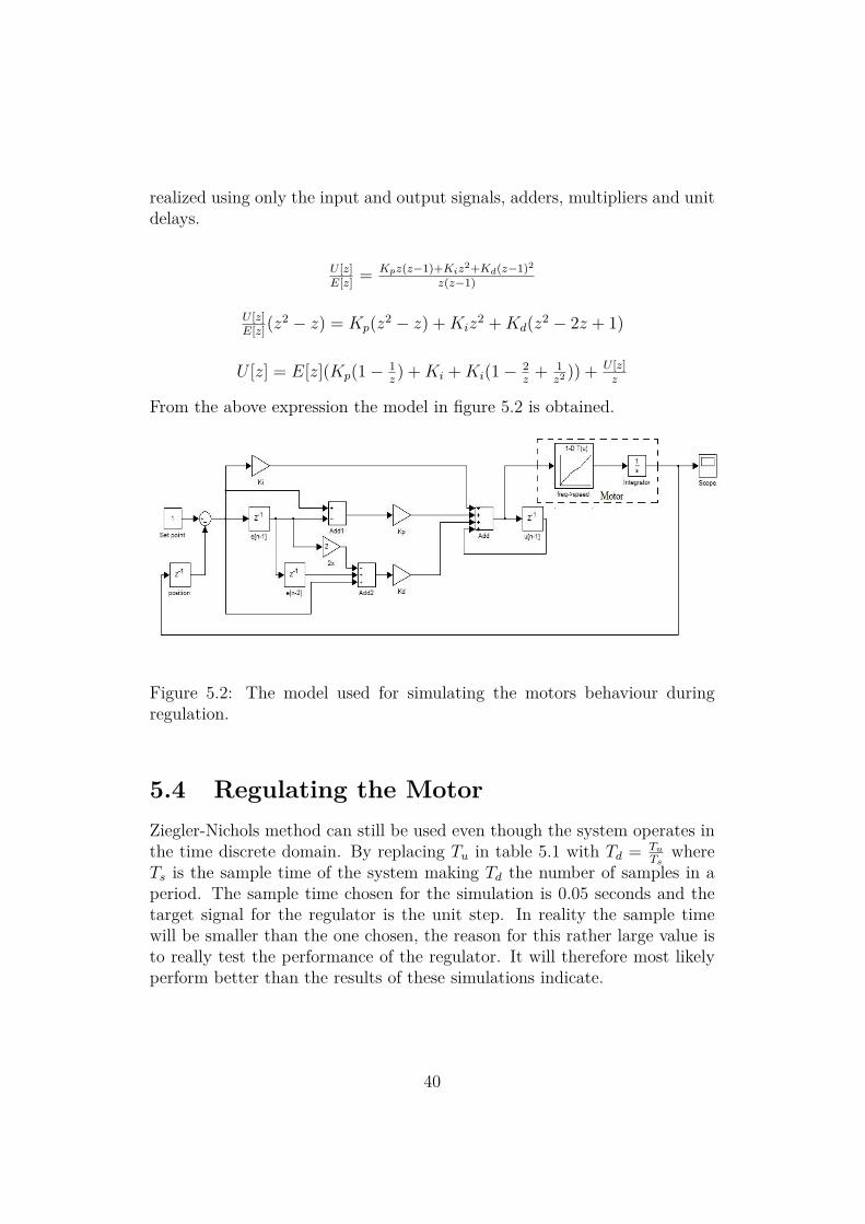
realized using only the input and output signals, adders, multipliers and unitdelays.
U [z]E[z] = Kpz(z−1)+Kiz
2+Kd(z−1)2
z(z−1)
U [z]E[z](z
2 − z) = Kp(z2 − z) +Kiz2 +Kd(z2 − 2z + 1)
U [z] = E[z](Kp(1− 1z) +Ki +Ki(1− 2
z+ 1
z2 )) + U [z]z
From the above expression the model in figure 5.2 is obtained.
Figure 5.2: The model used for simulating the motors behaviour duringregulation.
5.4 Regulating the MotorZiegler-Nichols method can still be used even though the system operates inthe time discrete domain. By replacing Tu in table 5.1 with Td = Tu
Tswhere
Ts is the sample time of the system making Td the number of samples in aperiod. The sample time chosen for the simulation is 0.05 seconds and thetarget signal for the regulator is the unit step. In reality the sample timewill be smaller than the one chosen, the reason for this rather large value isto really test the performance of the regulator. It will therefore most likelyperform better than the results of these simulations indicate.
40

The first step is as previously mentioned to set Ki and Kd to zero andfind a value for Kp which makes the ouput signal oscillate at a constantsamplitude. The signal oscillates between zero and two and with the targetsignal at one the amplitude has to be considered very large. This was ob-tained at Ku = 201.9 and the measured Td = 6 and can be seen in the figure5.3.
Figure 5.3: The first stage of Ziegler-Nichols method.
Using the values for a normal PID-controller from table 5.1 the newly ac-quired values of Ku and Td will calculate the values of the controller coeffi-cients. These values gives a raw regulator pictured in figure 5.4.
Figure 5.4: Result after Zeigler-Nichols method.
41
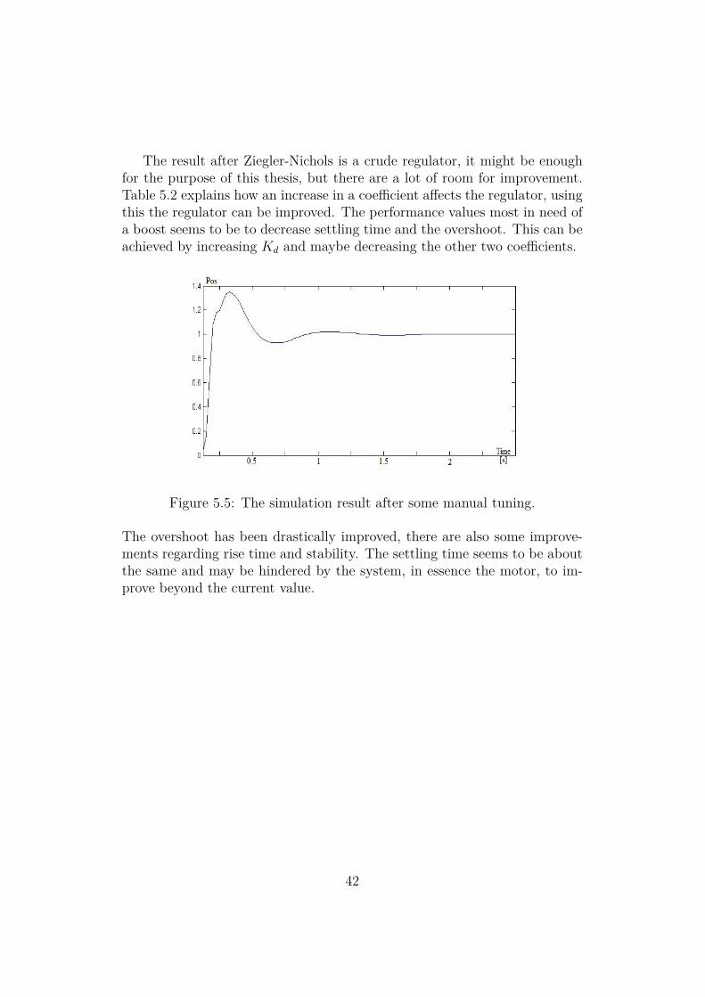
The result after Ziegler-Nichols is a crude regulator, it might be enoughfor the purpose of this thesis, but there are a lot of room for improvement.Table 5.2 explains how an increase in a coefficient affects the regulator, usingthis the regulator can be improved. The performance values most in need ofa boost seems to be to decrease settling time and the overshoot. This can beachieved by increasing Kd and maybe decreasing the other two coefficients.
Figure 5.5: The simulation result after some manual tuning.
The overshoot has been drastically improved, there are also some improve-ments regarding rise time and stability. The settling time seems to be aboutthe same and may be hindered by the system, in essence the motor, to im-prove beyond the current value.
42

5.5 Poles and Phase MarginThe pole placement and phase margin of the open loop system is of interest.The feedback in figure 5.2 needs to be removed and then by using the lin-earisation tool provided in Simulink the poles and phase margin can easilybe computed. Simulink provides the following pole zero diagram in the con-tinuous time domain: There is a pole in origin, since this model is based on
Figure 5.6: The pole zero diagram of the open loop.
approximations and ideal behaviour that means that there is a risk that thereal part of the pole is larger than zero and thus making the system unstable.Simulink also provides a bode plot which is shown below.
Figure 5.7: The bode plot of the open loop.
43

The circuit amplifies signals with low frequencies, as the frequency in-crease the gain decreases and levels out at around 11 rad/s where the gain is-18 dB. The phase margin is approximately 40 degrees, this paired with thebehaviour of the system makes it likely that the system is indeed stable.
44

Chapter 6
Improvements
At this point the system will be able to drive the motor and move the lensto a specified position. In theory it will at least perform adequately. Thereare still things that can be improved though which will be discussed in thischapter along with advantages and disadvantages of different solutions.
6.1 Evaluation of the Current CircuitAll in all the current circuit is well designed and there is no solution that isobviously better. The MCU lets the user interact with the system even whilethe system is running thus making the system versatile. It simplifies thedevelopment process since you can manually set position, motor frequencyand regulator coefficients and also read those values. Furthermore the useris also capable of starting and stopping the system. Of course the MCUcould be programmed to read and write other information as well as per thedevelopers wishes. The CPLD is necessary since as mentioned in chapter 5,the processor has other tasks that needs doing and the signal generation isan ongoing process that should not be interrupted.
There is one thing that could use quite a lot of improvement in the currentdesign though and that is the system clock. With the way the signal genera-tion works (explained in section 3.2.2) the period length of the driving signalsis an integer multiplied by the period length of the system clock. However,since there are four signals that needs to be generated and only one can beactive at a single time it follows that the smallest amount the period length ofa given driving signal is 100 ns or in other words four times the system clockperiod length. This is fine for larger motor where there is approximately50 valid values between 30 and 35 kHz and they will all make HT65 spin.
46

Between 60 and 65 kHz which is the active frequency range for P12 there areonly 13. This will negatively affect the regulators performance. Probablythe best solution would be to just replace the crystal oscillator with one thatoscillates at a higher frequency. If the system clock can not be changed forsome reason there are other ways to mitigate this flaw. There are plenty ofroom left on the CPLD and below two solutions to double the number ofvalid values is presented.
6.1.1 Clock Doubler
Figure 6.1: The schematics for a simple clock doubler.
One way to solve the current problem is to create a new clock signal. Themodel in figure 6.1 is bases upon the fact that there is a propagation delayin every gate and flip-flop. When the system clock toggles it will take oneCombinatorial logic delay (Tilo) for the new clock signal to go high, it willremain high for the sum of the time clock to Q-delay on the flip-flop andanother two Tilo due to the inverter and XNOR gate and the result shouldbe around 2 ns. Since there is 12.5 ns between toggles on the system clock itmeans that the duty cycle of the new clock signal will be small, but as longas the clock edges are detected by the CPLD this will not be problematic.To increase the duty cycle more inverters and flip-flops could be added to thedesign. This solution is not considered pretty since the quality of the clocksignal will decrease and should therefore not be a designers first choice [10].
47

Figure 6.2: The signals and how they affect each other.
6.1.2 Double CounterThe purpose of the clock on CPLD chip is to count clock pulses, it only countsthe positive edges though. That means that a system could be designed wheretwo counters work in parallel, with one counter counting the positive edges,one the negative edges and the add the results together. The CPLD can onlyhandle flip-flops that triggers on either the rising or falling edge so one haveto be chosen for the entire CPLD. This can be circumvented by introducingan inverter in front of one of the counters at the cost of a small delay whichis manageable. The block diagram of the counter can be seen in figure 6.3,the wave generator is just a state machine.
Figure 6.3: Block diagram of how the double counter is implemented.
48

6.1.3 ResultsThe effects of the solutions proposed in section 6.1.1 and 6.1.2 are the samefor the user. Figure 6.4 shows the results if one of these solutions are imple-mented, the solid line is the regular one and the dashed line is the outputwhen the counter works at double the speed. Everything seems to improve,the rise time is slightly better, the overshoot is less and the settling time is de-creased. Notice that this simulations differs from the one presented in figure5.5, this simulation was performed to emphasise the difference between themodified and the regular solution. These results may look a little better thanthey will appear in reality, however the previously mentioned improvementsoccurs for all simulations.
Figure 6.4: Solid line, unmodified; Dashed line, double counter speed.
6.2 Ideas for the RegulatorSimulations will only get you this far. The next step would be to hook upthe motor to the camera objective and get a lot of measurements of how thesystem performs. The regular PID controller might not work at a satisfactorylevel even after some tweaking of the coefficients so below are two quick fixesthat might improve the systems ability to regulate.
49

6.2.1 Derivative TermThe purpose of the derivative term is to improve stability, it does just thatin effect by dampening the system. However as a function of the regulatorerror the term is vulnerable to sudden changes in the input value which willcreate an abnormally large derivative term [11]. This can be remedied byletting the term be dependent on the current position instead, thus makingthe term measure the actual speed of the camera lens rather than by howfast the error is decreasing. This should make the system more stable andless erratic. So the new transfer function for the controller would be:
u[n] = Kpe[n] +Ki
n∑i=−∞
e[i] +Kd(y[n]− y[n− 1])
U [z] = E[z](Kp(1− 1z) +Ki) + Y [z]Kd(1
z− 1
z2 ) + U [z]z
6.2.2 Limiting the ErrorThe integral term is the sum of all past errors, hence unusually large errorscan affect the system and decrease performance. Therefore it can be benefi-cially to set a maximum limit for the error. The position is given by a 16 bitnumber and the error can potentially be of the same magnitude. By limitingthe error to a number with less than 16 bits the overall performance of thesystem may improve.The regulator will experience a decrease in rise time,but hopefully an increase in settling time and decrease in overshoot.
50


Chapter 7
Conclusion
The purpose of this thesis was to find it if it would be possible to modify anexisting autofocusing system to make it work for a smaller motor. With afair amount of certainty it can be concluded that, yes it is possible. The onlydoubt would be that the since the smaller motor is not as powerful as thelarger one it may not be able to drive the lens at a satisfactory level. Theeffects of how heat affects the motors performance is not entirely clear.
As long as the transformers are matched to the required input voltage of aspecific motor it would be fairly easy to configure the circuit board for anymotor, so the results are not just limited to the motors used in this thesis.Regardless of the size of the motor it should probably be placed outside thecamera objective and thus make the motor drive geared. This will mean thatthe system will be quicker and stronger at the cost of maximum speed. Atrade worth making in this case.
The goal on the horizon was to make a circuit that performs on the same levelas the original circuit, here the results are inconclusive. Due to limitationsin tools and no possibility to connect the motor to an actual camera lens theresults are in a large part theoretical. The concrete results have shown thatthe circuit board can drive the motor, but the circuits ability to regulateis not certain. The simulations and knowledge about the previous systemindicates that it will not be a problem, but there is no way to be sure beforereal live tests.
52

Bibliography
[1] Texas Instrument MSC1202 data sheet, available athttp://pdf1.alldatasheet.com/datasheet-pdf/view/104509/BURR-BROWN/MSC1202.html (2012-07-15)
[2] MCS 51 Microcontroller Family User’s Guide, February 1994, Publicationnumber 121517, Intel Corporation
[3] Homepage of the SDCC project, http://sdcc.sourceforge.net/ (2012-06-14)
[4] Toshiiku Sashida and Takashi Kenjo, An introduction to ultrasonic mo-tors, Oxford university press, 2001
[5] Ilie Romaniuc, An introduction to ultrasonic piezoelectric motors, AGIRbulletin nr. 4/2011, available at http://www.agir.ro/buletine/1048.pdf(2012-07-16)
[6] Güngör Bal, A digitally controlled drive system for travelling-wave ultra-sonic motor, Gazi University, 2003
[7] Tomonobu Senjyu, Katsumi Uezato and Hiroshi Miyazato, Adjustablespeed control of ultrasonic motors by adaptive control, IEEE TransactionsPower Electronics, vol. 10, no.5, 1995
[8] Tomohiro Yoshida, Tomonobu Senjyu, Mitsuru Nakamura, NaomitsuUrasaki, Toshihisa Funabashi and Hideomi Sekine, Sensorless control ofultrasonic motors using neural network, Journal of Power Electronics, vol.6, no.1, 2006
[9] Torkel Glad and Lennart Ljung, Reglerteknik, Grundläggande teori, Stu-dentlitteratur, 2006
[10] Peter Alfke, Six Easy Pieces,http://www.pldworld.com/_xilinx/html/tip/sixeasypieces.htm(2013-01-10)
53

[11] AVR221: Discrete PID controller, available athttp://www.atmel.com/images/doc2558.pdf (2013-01-31)
54

Typ av publikation
Examensarbete
ISBN (licentiatavhandling)
ISRN
LiTH-ISY-EX--13/4659--SE
Serietitel (licentiatavhandling)
Serienummer/ISSN
(licentiatavhandling)
Språk Engelska/English
Antal sidor 54
Presentationsdatum 2013-04-25
Publiceringsdatum (elektronisk version)
Institution och avdelning ISY
Department of electrical engineering
URL för elektronisk version http://urn.kb.se/resolve?urn=urn:nbn:se:liu:diva-4659 (Ersätt xxxx med det korrekta numret)
Publikationens titel Driver circuit for an ultrasonic motor
Författare Henrik Ocklind
Sammanfattning To make a camera more user friendly or let it operate without an user the camera objective needs to be able to put the
camera lens in focus. This functionality requires a motor of some sort, due to its many benefits the ultrasonic motor is a
preferred choice. The motor requires a driving circuit to produce the appropriate signals and this is what this thesis is about.
The
main difficulty that needs to be considered is the fact that the ultrasonic motor is highly non-linear.
This paper will give a brief walk through of how the ultrasonic motor works,its pros and cons and how to control it. How the
driving circuit is designed and what role the various components fills. The regulator is implemented in C-code and runs on a
micro processor while the actual signal generation is done on a CPLD. The report ends with a few suggestions of how to
improve the system should the presented solution not perform at a satisfactory level.
Antal sidor: 54
Nyckelord Ultrasonic motor, electronics, regulator, CPLD, micro processor, embedded system