
A FINITE ELEMENT APPROACH FOR THE - DORAS -...
167
A FINITE ELEMENT APPROACH FOR THE IMPLEMENTATION OF MAGNETOSTRICTIVE MATERIAL TERFENOL-D IN AUTOMOTIVE CNG FUEL INJECTION ACTUATION by H. A. CHOWDHURY B. Sc. Engg. (ME), MASME, MSAE A thesis submitted for the degree of Master of Engineering School of Mechanical and Manufacturing Engineering Faculty of Engineering and Computing Dublin City University July 2008 Supervisor DR. ABDUL GHANI OLABI M.Eng 2008
-
Upload
truonghanh -
Category
Documents
-
view
216 -
download
0
Transcript of A FINITE ELEMENT APPROACH FOR THE - DORAS -...

A FINITE ELEMENT APPROACH FOR THE
IMPLEMENTATION OF
MAGNETOSTRICTIVE MATERIAL
TERFENOL-D IN AUTOMOTIVE CNG FUEL
INJECTION ACTUATION
by
H. A. CHOWDHURY
B. Sc. Engg. (ME), MASME, MSAE
A thesis submitted for the degree of Master of Engineering
School of Mechanical and Manufacturing Engineering Faculty of Engineering and Computing
Dublin City University
July 2008
Supervisor DR. ABDUL GHANI OLABI
M.Eng 2008

Declaration
I hereby certify that this material, which I now submit for assessment on the
programme of study leading to the award of Master of Engineering is entirely my
own work, that I have exercised reasonable care to ensure that the work is original,
and does not to the best of my knowledge breach any law of copyright, and has not
been taken from the work of others save and to the extent that such work has been
cited and acknowledged within the text of my work.
………………………………………....
H. A. CHOWDHURY
Student ID Number: 54179416
Date: July 2008
ii

Dedications
TO MY BELOVED
MAA (HOSNE ARA BEGUM)
&
BABA
(NURUL AMIN CHOWDHURY)
iii

Acknowledgments
First and foremost, I offer my sincerest gratitude to my supervisor, Dr. Abdul
Ghani Olabi, who has supported me throughout my research with his patience and
diligence. I would like to express my appreciation towards him for providing me
with the unique opportunity to work with this interesting research topic, for his
assistance and his expert guidance throughout the research. I would also like to thank
Prof. Saleem Hashmi, for his tremendously erudite and inspiring conversations from
time to time. Furthermore, I could not help myself from expressing my earnest
admiration towards their remarkable support during my physical disability which
was once hampering my research enormously. Therefore, at this point of
acknowledgement, when I look back at those exasperating moments, I could feel
nothing but respectful and thankful towards them.
I would like to thank my friend and colleague Dr. Saiful Amri Mazlan for his
implausible support regarding exchanging ideas and arguments at my workplace,
which facilitated in acquiring diverse knowledge in the field of smart materials. I
would also like to thank Nasser Ekreem and Andrew Clarke for their suggestions,
resources and encouragement.
In my daily work, I have been truly blessed with a friendly and cheerful
group of fellow colleagues. Consequently, I would like to thank Dr. Ezzeddin
Hassan, Hussam Achour and Dr. Mohammed Dabnoon.
The School of Mechanical and Manufacturing Engineering has provided the
multiple software support that I have needed to perform and complete my research.
Finally, I would like to thank all my family members for their unconditional
love and support throughout my studies.
iv

Abstract Magnetostriction is the deformation that spontaneously occurs in ferromagnetic materials when an external magnetic field is applied. In applications broadly defined for actuation, magnetostrictive material Terfenol-D possesses intrinsic rapid response times while providing small and accurate displacements and high-energy efficiency, which are some of the essential parameters required for fast control of fuel injector valves for decreased engine emissions and lower fuel consumption compared with the traditional solenoid fuel injection system.
A prototype CNG fuel injector assembly was designed, which primarily included magnetostrictive material Terfenol-D as the actuator material, 1020 Steel having soft magnetic properties as the injector housing material, AWG copper wire as the coil material and 316 Stainless Steel having non-magnetic properties as the plunger material. A 2D cross-sectional geometry including the injector housing, coil, Terfenol-D shaft, and plunger, was modeled in both Finite Element Method Magnetics (FEMM) and ANSYS for 2D axisymmetric magnetic simulation. The magnetic simulations were performed in order to determine the coil-circuit parameters and the magnetic field strength to achieve the required magnetostrictive strain, and consequently, the injector needle lift. The FEMM magnetic simulations were carried out with four different types of AWG coil wires and four different injector coil thicknesses in order to evaluate the relationship between the different coil types and thicknesses against the achieved strain or injector lift. Eventually, the optimized parameter obtained from FEMM results analysis was verified against ANSYS electromagnetic simulation.
Subsequently, a three dimensional replica of the CNG flow conduit was modelled in GAMBIT with the resultant injector lift. The meshed conduit was then simulated in FLUENT using the 3D time independent segregated solver with standard k-ε,
realizable k-ε and RSM turbulent models to predict the mass flow rate of CNG to be injected. Eventually, the simulated flow rates were verified against mathematically derived static flow rate required for a standard automotive fuel injector considering standard horsepower, BSFC and injector duty cycle.
v

Table of Contents
Declaration …………………….………..………..……………………………. ii
Dedications ……...……………………………………………………………... iii
Acknowledgements ………………………………...………………………….. iv
Abstract ……………………...………………………………………………… v
List of Tables ………………...…………….………………………………….. xi
List of Figures …………………………………………………………………. xii
CHAPTER ONE : INTRODUCTION
1.1 Introduction...................................................................................................... 1
1.2 Motivation and purpose of study ..................................................................... 2
1.3 Outline of thesis ............................................................................................... 3
CHAPTER TWO : LITERATURE REVIEW OF CNG FUEL INJECTION
ENVIRONMENTS
2.1 Introduction...................................................................................................... 5
2.2 Compressed natural gas ................................................................................... 6
2.3 Dedicated natural gas engines (mono-fuel)...................................................... 7
2.3.1 Direct injection............................................................................................. 7
2.3.1.1 Direct injection strategies .................................................................... 7
2.3.1.2 Timings of fuel injection and ignition ................................................ 10
2.3.1.3 Fuel injector ....................................................................................... 10
2.3.1.4 Injector driver .................................................................................... 11
2.3.1.5 Nozzles ............................................................................................... 11
2.3.2 Stratified charge combustion...................................................................... 12
2.4 Compressed natural gas in diesel environment.............................................. 13
2.4.1 Pilot ignited high pressure direct injection of natural gas.......................... 13
2.4.1.1 Diesel pilot injection strategy ............................................................ 13
vi

2.4.2 Direct injection with hot surface ignition .................................................. 14
2.4.2.1 Hot surface ignition strategy.............................................................. 14
2.4.3 Dual-fuel diesel engine with induced natural gas ...................................... 16
2.4.3.1 Dual-fuel diesel engine with induced NG strategy ............................ 16
2.4.4 Natural gas combustion assisted with gas-oil in a diesel engine ............... 18
2.5 Compressed natural gas in gasoline environment.......................................... 18
2.5.1 CNG as an alternative fuel for a retrofitted gasoline vehicle..................... 18
2.5.2 Natural gas direct injection in spark ignited Otto cycle engine ................. 19
2.6 Compressed natural gas and hydrogen........................................................... 20
2.6.1 Hydrogen assisted jet ignition (HAJI)........................................................ 20
2.6.1.1 HAJI strategy ..................................................................................... 21
2.7 Summary of chapter two ................................................................................ 22
CHAPTER THREE : LITERATURE REVIEW OF SMART MATERIALS
3.1 Introduction...................................................................................................... 24
3.2 Actuator Materials............................................................................................ 24
3.3 Mechanism of Magnetostriction ...................................................................... 26
3.4 Fuel Injection ................................................................................................... 30
3.4.1 Prospect for smart materials ...................................................................... 30
3.4.2 Comparative discussion between conventional solenoid injection and
injection actuated by smart materials..................................................................... 31
3.5 Magnetostrictive Material Terfenol-D ............................................................. 34
3.5.1 Terfenol-D properties ................................................................................ 34
3.5.2 Young’s modulus of Terfenol-D ............................................................... 36
3.5.3 The magnetomechanical coupling factor and the
magnetostrictive coefficient ................................................................................... 37
3.5.4 Quality factor............................................................................................. 39
3.5.5 Permeability of Terfenol-D ....................................................................... 39
3.5.6 Hysteresis loop of Terfenol-D................................................................... 41
3.5.7 Blocked force of Terfenol-D ..................................................................... 43
3.6 Measurements of magnetostriction .................................................................. 44
3.7 Production of smart materials .......................................................................... 44
vii

3.8 Piezoelectric non-linearity ............................................................................... 45
3.9 Real-time control of magnetostrictive actuators .............................................. 46
3.10 Recent developments ....................................................................................... 47
3.11 Summary of chapter three ................................................................................ 49
CHAPTER FOUR : FUEL INJECTOR DESIGN CONCEPT AND
ACTUATING PARAMETER DETERMINATION
4.1 Introduction...................................................................................................... 51
4.2 Prototype CNG fuel injector ............................................................................ 51
4.2.1 Mechanism of the fuel injector.................................................................. 52
4.3 Fuel injector component material properties.................................................... 54
4.3.1 1020 Steel .................................................................................................. 54
4.3.2 Grade 316 Stainless Steel .......................................................................... 55
4.4 Actuating parameter determination.................................................................. 56
4.5 Summary of chapter four ................................................................................. 59
CHAPTER FIVE : FEMM MAGNETIC FIELD SIMULATION
5.1 Introduction...................................................................................................... 61
5.2 Relevant Partial Differential Equations ........................................................... 61
5.2.1 Magnetostatic problems ............................................................................ 61
5.2.2 Time-harmonic magnetics problem........................................................... 62
5.3 Model Construction and Analysis.................................................................... 63
5.3.1 Problem definition and creating model geometry ..................................... 65
5.3.2 Boundary conditions.................................................................................. 67
5.3.3 Material and circuit properties................................................................... 69
5.3.4 Meshed geometry ...................................................................................... 71
5.4 FEMM analysis results..................................................................................... 72
5.4.1 Magnetostatic series circuitry.................................................................... 72
5.4.2 Magnetostatic parallel circuitry................................................................. 77
5.4.3 Time-harmonic series circuitry.................................................................. 81
5.5 Summary of chapter five.................................................................................. 84
viii
CHAPTER SIX : ANSYS ELECTROMAGNETIC VERIFICATION
6.1 Introduction...................................................................................................... 86
6.2 Low-frequency electromagnetic analysis......................................................... 86
6.2.1 Element type used in 2-D static magnetic analysis ................................... 87
6.2.2 Magnetic formulation ................................................................................ 88
6.3 ANSYS Electromagnetic nodal analysis preprocessor .................................... 89
6.3.1 Geometry modeling................................................................................... 89
6.3.2 Defining element type and material properties ......................................... 90
6.3.3 Meshed geometry ...................................................................................... 92
6.3.4 Applying magnetic excitation and boundary condition............................. 93
6.4 ANSYS Electromagnetic results ...................................................................... 94
6.5 ANSYS and FEMM results verification .......................................................... 97
6.6 Summary of chapter six ................................................................................... 99
CHAPTER SEVEN : CNG FUEL INJECTOR MASS FLOW RATE
PREDICTION BY FLUENT
7.1 Introduction.................................................................................................... 101
7.2 Turbulence models ......................................................................................... 102
7.2.1 The Standard k − ε model....................................................................... 102
7.2.2 The Realizable k − ε model ..................................................................... 103
7.2.3 The Reynolds Stress Model (RSM)......................................................... 104
7.3 Modeling of the CNG conduit........................................................................ 104
7.3.1 Geometry creation ................................................................................... 104
7.3.2 Specifying zone types.............................................................................. 107
7.3.3 Meshing ................................................................................................... 107
7.3.3.1 Mesh checking ...................................................................................... 109
7.3.4 FLUENT solver ....................................................................................... 110
7.4 FLUENT simulation results ........................................................................... 111
7.4.1 Sample calculation of injector flow rate.................................................. 113
7.5 Summary of chapter seven ............................................................................. 115
ix

CHAPTER EIGHT : CONCLUSIONS & RECOMMENDATIONS
8.1 Conclusions.................................................................................................. 117
8.2 Contributions of the thesis ........................................................................... 119
8.3 Recommendations for future work .............................................................. 119
8.4 Summary of chapter eight ............................................................................ 120
REFERENCES..……………………………………………………………...... 121 APPENDICES
Appendix A : Publications…..……………………………………… I Appendix B : CAD drawings……………………………………….. II Appendix C : FEMM magnetostatic simulation results…………….. IV
x

List of Tables
Table 2.1 : Properties of some conventional fuels and CNG………………… 6
Table 3.1 : Terfenol-D properties…………………………………………….. 35Table 3.2 : Relative permeability of different ferromagnetic materials……… 40
Table 4.1 : Typical material properties of 1020 Steel………………………... 54Table 4.2 : Typical material properties of 316 Stainless Steel……………….. 56Table 4.3 : Required parameters to achieve in simulation……………………. 58
Table 5.1 : Table of AWGs…………………………………………………… 64Table 5.2 : Coil number of turns in layers……………………………………. 65Table 5.3 : Comparison between data analysis and FEMM result for 22
AWG with 5 mm coil thickness………………………………….. 75Table 5.4 : Summary of the results between series and parallel circuit
properties…………………………………………………………. 81
Table 6.1 : Assigned material model number in ANSYS…………………….. 92Table 6.2 : Percentage error calculation for FEMM and ANSYS flux density
output……………………………………………………………... 98
Table 7.1 : Zone type specifications………………………………………….. 107Table 7.2 : GAMBIT mesh investigation…………………………………….. 109Table 7.3 : Assumptions for CFD analysis…………………………………… 111Table 7.4 : Results of mass flow rates at the pressure outlet of the injector for
Pinlet: 85 psig, Poutlet: 0 psig……………………………………….. 113Table 7.5 : Assumptions for sample fuel flow calculation…………………… 114Table 7.6 : Percentage difference between simulated and numerically derived
mass flow rate…………………………………………………….. 115
xi

List of Figures
FIGURE OF CHAPTER ONE
Figure 1.1 : Summary of the research process in chapter one………………… 4
FIGURES OF CHAPTER TWO Figure 2.1 : Arrangements of the fuel injectors and the spark gap; (a) opposed
and single injection, spark gap at centre and halfway between centre and wall, and (b) parallel injection with spark gap at centre……………………………………………………………... 8
Figure 2.2 : Schematic of diesel pilot ignition with natural gas DI…………… 14Figure 2.3 : Glow plug ignition………………………………………………... 15Figure 2.4 : Concept of biform mixture formation in different piston cavity
space in a dual-fuel engine; (a) Diesel fuel injection at 60° CA BTDC, and (b) Biform mixture formation at end of compression………………………………………………………. 17
Figure 2.5 : Schematic of hydrogen assisted jet ignition……………………… 21Figure 2.6 : Summary of the research process in chapter two………………… 23
FIGURES OF CHAPTER THREE
Figure 3.1 : Joule magnetostriction. (a) The changes in shape in response to the magnetic field H. H is proportional to the current that passes through the solenoid. (b) The relationship between ΔL/L and H………………………………………………………………….. 27
Figure 3.2 : Graphical representation of strain vs. magnetic field (idealized behaviour)………………………………………………………… 28
Figure 3.3 : Schematic of strain vs. magnetic field……….…………………... 28Figure 3.4 : Application of compressive load to magnetostrictive materials….. 29Figure 3.5 : Traditional fuel injector; (a) solenoid off, valve closed position;
(b) solenoid on, plunger movement and valve open position…….. 32Figure 3.6 Cross section of a prototypical Terfenol-D magnetostrictive
transducer………………………………………………………… 34Figure 3.7 : Length change versus Terfenol-D rod with strain as parameter….. 36Figure 3.8 : Young's modulus versus magnetic field………………………….. 36Figure 3.9 : Strain versus magnetic field……………………………………… 38
xii

Figure 3.10 : k33 and d33 versus applied stress………………………………….. 38Figure 3.11 : Hysteretic magnetization curve for ferromagnetic material……… 41Figure 3.12 : General B-H curve of Terfenol-D………………………………... 42Figure 3.13 : Full loop of magnetization………………………………………... 42Figure 3.14 : Summary of the research process in chapter three……………….. 50 FIGURES OF CHAPTER FOUR
Figure 4.1 : Prototype CNG fuel injector assembly…………………………… 52Figure 4.2 : CNG inlet-outlet port and needle valve…………………………... 53Figure 4.3 : Non-linear B-H data of 1020 Steel from FEMM materials
Library……………………………………………………………. 55Figure 4.4 : Terfenol-D strain vs. applied field at various preloads, data from
ETREMA PRODUCTS INC……………………………….. 57Figure 4.5 : Hysteretic magnetization curve for a ferromagnetic material and
relevant points: BBR, remnance; (HS, BSB ), saturation; and HC, coercitive field strength…………………………………………... 57
Figure 4.6 : B-H data of Terfenol-D, data from ETREMA PRODUCTS INC... 58Figure 4.7 : Summary of the research process in chapter four………………... 60 FIGURES OF CHAPTER FIVE
Figure 5.1 : Injector components for FEMM simulation……………………… 64Figure 5.2 : Problem definition in FEMM…………………………………….. 66Figure 5.3 : Injector geometry in FEMM with four coil thicknesses………….. 67Figure 5.4 : Applying boundary conditions in FEMM………………………... 69Figure 5.5 : Adding material properties to the model…………………………. 70Figure 5.6 : Constructing Terfenol-D material model in FEMM……………... 70Figure 5.7 : Meshed geometry in FEMM……………………………………... 71Figure 5.8 : Power vs. current for coil thickness; (a) t = 2mm; (b) t = 3mm;
(c) t = 4mm and (d) t = 5mm……………………………………... 72Figure 5.9 : Average flux density vs. current for coil thickness; (a) t = 2mm;
(b) t = 3mm; (c) t = 4mm and (d) t = 5mm……………………….. 73
xiii

Figure 5.10 : Current, power and voltage variation at flux density, B = 0.55 Tesla for coil thickness; (a) t = 2mm; (b) t = 3mm; (c) t = 4mm and (d) t = 5mm…………………………………………………... 74
Figure 5.11 : Flux density plot for 22 AWG with 672 turns in 8 layers;
coil thickness, t = 5 mm…………………………………………... 76Figure 5.12 : Change of flux density at different sections along the 15 mm
half-section of the Terfenol-D shaft for 22 AWG with 672 turns in 8 layers………………………………………………………… 76
Figure 5.13 : Parallel circuit…………………………………………………….. 77Figure 5.14 : Parallel coil circuitry in FEMM………………………………….. 78Figure 5.15 : Flux density variation for parallel and series coil circuitry………. 79Figure 5.16 : Change of flux density at different sections along the 15 mm
half-section of the Terfenol-D shaft for 22 AWG with 672 turns in 8 layers (t = 5 mm)…………………………………………….. 80
Figure 5.17 : The parallel circuit properties for 22 AWG with 672 turns in 8 layers (t = 5 mm)…………………………………………………. 80
Figure 5.18 : Variation of flux density for 22 AWG with 672 turns in 8 layers with 4.07 amps input current; (a) flux density vs. distance at different frequencies; (b) zoom in view of flux density vs. distance showing for 100 Hz and 250 Hz; (c) zoom in view of flux density vs. distance showing for 10 Hz, 20 Hz, 50 Hz and 100 Hz; (d) Flux density vs. frequency at the points (0,0), (5,0) and (10,0)…………………………………………………………. 82
Figure 5.19 : FEMM time-harmonic series circuitry results output……………. 83Figure 5.20 : Summary of the research process in chapter five………………… 85 FIGURES OF CHAPTER SIX
Figure 6.1 : Current density…………………………………………………… 87Figure 6.2 : PLANE13 element type geometry with nodes I, J, K and L……... 88Figure 6.3 : 2-D cross-sectional geometry in ANSYS showing line and area
plot………………………………………………………………... 90Figure 6.4 : Defining PLANE13 element type………………………………... 91Figure 6.5 : (a) Defining material model behavior, (b) Terfenol-D B-H data
input………………………………………………………………. 91Figure 6.6 : Defining mesh attributes by area…………………………………. 92Figure 6.7 : Meshed geometry in ANSYS…………………………………….. 93Figure 6.8 : Applying current density and boundary condition……………….. 94
xiv

Figure 6.9 : Magnetostatic options and solutions……………………………... 94Figure 6.10 : (a) 2D flux lines; (b) Flux density vector sum nodal solution……. 95Figure 6.11 : Flux density vector sum vector plot for 2D ½ expansion………… 96Figure 6.12 : Electromagnetic force calculation, (a) Nodal solution, and (b)
Vector plot………………………………………………………... 96Figure 6.13 : Flux density vector sum vector plot; (a) FEMM output, and
(b) ANSYS output………………………………………………... 97Figure 6.14 : Flux density distribution along the indicated contour lines………. 98Figure 6.15 : Summary of the research process in chapter six…………………. 100 FIGURES OF CHAPTER SEVEN
Figure 7.1 : Pro-Engineer model of the CNG flow conduit…………………… 105Figure 7.2 : Importing Pro-E model as IGES in GAMBIT……………………. 106Figure 7.3 : Imported CNG flow conduit model in GAMBIT………………… 106Figure 7.4 : Meshed geometry in GAMBIT…………………………………... 108Figure 7.5 : Equi-angle skewness quality……………………………………... 109Figure 7.6 : Overview of the segregated solution method…………………….. 110Figure 7.7 : Velocity vector colored by static pressure (Pa)…………………... 112Figure 7.8 : Summary of the research process in chapter seven………………. 116 FIGURES OF CHAPTER EIGHT
Figure 8.1 : Summary of the research process in chapter eight……………….. 120 FIGURES OF APPENDIX B
Figure B1 : Injector housing…………………………………………………... IIFigure B2 : Needle valve……………………………………………………… IIFigure B3 : Plunger……………………………………………………………. IIIFigure B4 : Closing spring…………………………………………………….. III
xv

FIGURES OF APPENDIX C
Figure C1 : Variation of power and average flux density with current at coil thickness, t = 2 mm for; (a) 22 AWG, (b) 24 AWG, (c) 28 AWG and (d) 30 AWG………………………………………………….. IV
Figure C2 : Variation of power and average flux density with current at coil
thickness, t = 3 mm for; (a) 22 AWG, (b) 24 AWG, (c) 28 AWG and (d) 30 AWG………………………………………………….. V
Figure C3 : Variation of power and average flux density with current at coil thickness, t = 4 mm for; (a) 22 AWG, (b) 24 AWG, (c) 28 AWG and (d) 30 AWG………………………………………………….. VI
Figure C4 : Variation of power and average flux density with current at coil thickness, t = 5 mm for; (a) 22 AWG, (b) 24 AWG, (c) 28 AWG and (d) 30 AWG………………………………………………….. VII
xvi

CHAPTER ONE
INTRODUCTION
Chapter One - Introduction
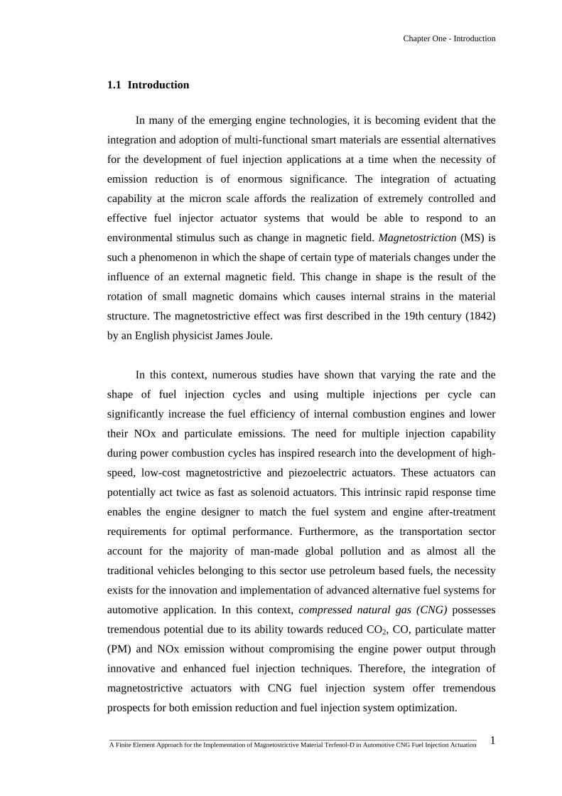
1.1 Introduction
In many of the emerging engine technologies, it is becoming evident that the
integration and adoption of multi-functional smart materials are essential alternatives
for the development of fuel injection applications at a time when the necessity of
emission reduction is of enormous significance. The integration of actuating
capability at the micron scale affords the realization of extremely controlled and
effective fuel injector actuator systems that would be able to respond to an
environmental stimulus such as change in magnetic field. Magnetostriction (MS) is
such a phenomenon in which the shape of certain type of materials changes under the
influence of an external magnetic field. This change in shape is the result of the
rotation of small magnetic domains which causes internal strains in the material
structure. The magnetostrictive effect was first described in the 19th century (1842)
by an English physicist James Joule.
In this context, numerous studies have shown that varying the rate and the
shape of fuel injection cycles and using multiple injections per cycle can
significantly increase the fuel efficiency of internal combustion engines and lower
their NOx and particulate emissions. The need for multiple injection capability
during power combustion cycles has inspired research into the development of high-
speed, low-cost magnetostrictive and piezoelectric actuators. These actuators can
potentially act twice as fast as solenoid actuators. This intrinsic rapid response time
enables the engine designer to match the fuel system and engine after-treatment
requirements for optimal performance. Furthermore, as the transportation sector
account for the majority of man-made global pollution and as almost all the
traditional vehicles belonging to this sector use petroleum based fuels, the necessity
exists for the innovation and implementation of advanced alternative fuel systems for
automotive application. In this context, compressed natural gas (CNG) possesses
tremendous potential due to its ability towards reduced CO2, CO, particulate matter
(PM) and NOx emission without compromising the engine power output through
innovative and enhanced fuel injection techniques. Therefore, the integration of
magnetostrictive actuators with CNG fuel injection system offer tremendous
prospects for both emission reduction and fuel injection system optimization.
_______________________________________________________________________________________________________________ A Finite Element Approach for the Implementation of Magnetostrictive Material Terfenol-D in Automotive CNG Fuel Injection Actuation
1
Chapter One - Introduction
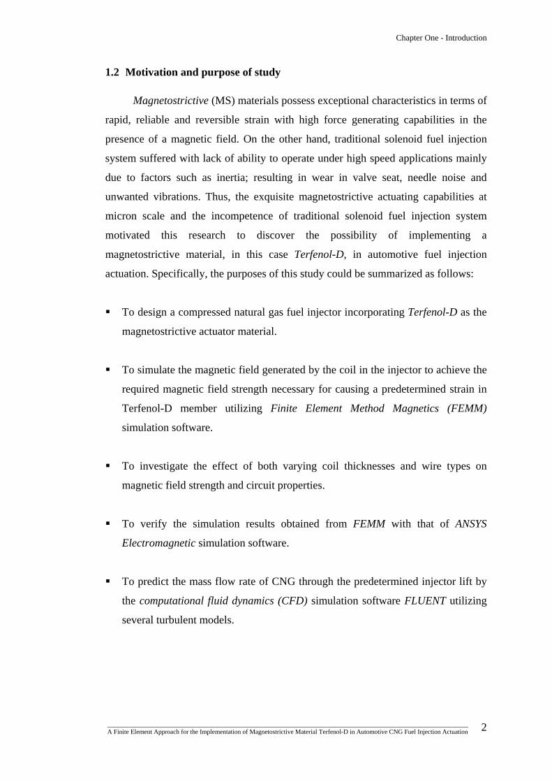
1.2 Motivation and purpose of study
Magnetostrictive (MS) materials possess exceptional characteristics in terms of
rapid, reliable and reversible strain with high force generating capabilities in the
presence of a magnetic field. On the other hand, traditional solenoid fuel injection
system suffered with lack of ability to operate under high speed applications mainly
due to factors such as inertia; resulting in wear in valve seat, needle noise and
unwanted vibrations. Thus, the exquisite magnetostrictive actuating capabilities at
micron scale and the incompetence of traditional solenoid fuel injection system
motivated this research to discover the possibility of implementing a
magnetostrictive material, in this case Terfenol-D, in automotive fuel injection
actuation. Specifically, the purposes of this study could be summarized as follows:
To design a compressed natural gas fuel injector incorporating Terfenol-D as the
magnetostrictive actuator material.
To simulate the magnetic field generated by the coil in the injector to achieve the
required magnetic field strength necessary for causing a predetermined strain in
Terfenol-D member utilizing Finite Element Method Magnetics (FEMM)
simulation software.
To investigate the effect of both varying coil thicknesses and wire types on
magnetic field strength and circuit properties.
To verify the simulation results obtained from FEMM with that of ANSYS
Electromagnetic simulation software.
To predict the mass flow rate of CNG through the predetermined injector lift by
the computational fluid dynamics (CFD) simulation software FLUENT utilizing
several turbulent models.
_______________________________________________________________________________________________________________ A Finite Element Approach for the Implementation of Magnetostrictive Material Terfenol-D in Automotive CNG Fuel Injection Actuation
2

Chapter One - Introduction
1.3 Outline of thesis
This thesis is organized in eight chapters. A concise and inclusive overview of
the highlighted research process is shown in figure 1.1. Each respective chapter in
this thesis ends with a brief summary outlining the foremost achievements and
findings. The remainder of this thesis is organized as shown:
Chapter Two: This chapter incorporates a comprehensive literature review
of various compressed natural gas fuel injection
environments.
Chapter Three: This chapter incorporates basic principles and properties of
smart materials especially for MS material Terfenol-D.
Chapter Four: This chapter incorporates the design concept and
mechanism of a prototype CNG fuel injector. Besides, the
actuating parameters required to initiate the electromagnetic
and CFD simulations would be predetermined.
Chapter Five: This chapter incorporates the discussion and analysis of
FEMM simulation results.
Chapter Six: This chapter incorporates the verification of FEMM
simulation results with that of ANSYS Electromagnetic.
Chapter Seven: This chapter incorporates the prediction of mass flow rate of
the CNG fuel injector utilizing standard k-ε, realizable k-ε
and Reynolds Stress Model (RSM) turbulent models in
FLUENT CFD software.
Chapter Eight: This chapter incorporates conclusions and highlights of the
research contribution with recommendations for future
research work.
_______________________________________________________________________________________________________________ A Finite Element Approach for the Implementation of Magnetostrictive Material Terfenol-D in Automotive CNG Fuel Injection Actuation
3

Chapter One - Introduction
Introduction Prospect for integrating magnetostrictive material in CNG fuel injection actuation
Motivation - Exquisite magnetostrictive actuating capabilities at micron scale.
- Incompetence of traditional solenoid fuel injection system.
Purpose of the study
- Design CNG fuel injector with Terfenol-D actuator - FEMM Magnetic field simulation - Investigate different effects on magnetic field strength - ANSYS Electromagnetic verification - CNG injector mass flow rate prediction by FLUENT
1
Sequence Resource Research task Legend:
8 Research Outcome
FLUENT Fuel Flow Rate Prediction
4
6
5 FEMM Magnetic Field Simulation
ANSYS Electromagnetic Verification
7
Prototype Fuel Injector Design
2, 3 Literature Review
- CNG fuel injection - Smart materials
Point of Departure
Figure 1.1: Summary of the research process in chapter one.
_______________________________________________________________________________________________________________ A Finite Element Approach for the Implementation of Magnetostrictive Material Terfenol-D in Automotive CNG Fuel Injection Actuation
4
CHAPTER TWO
LITERATURE REVIEW
OF
CNG FUEL INJECTION
ENVIRONMENTS
Chapter Two - Literature Review of CNG Fuel Injection Environments
2.1 Introduction
Natural gas vehicles (NGVs) can be made to operate only on natural gas or can
be designed to run on either natural gas or gasoline. Generally, these spark-ignited or
Otto-cycle engines are referred to as bi-fuel vehicles. On the other hand, diesel
engines, which operate according to the principle of a compression ignition or heat of
compression engine, can be run on a combination of natural gas and diesel fuel
mixed inside the combustion chamber. In this case, small amounts of diesel fuel
mixed with natural gas act as mini-spark plugs to allow the natural gas to ignite.
Normally when the vehicle is idling, the engine will run totally on diesel fuel. But
when the vehicle begins to move, natural gas begins to replace the diesel fuel, which
in most cases can be up to about 80-85%. These are known as dual-fuel natural gas
engines.
According to a classification by European Natural Gas Vehicle Association
(ENGVA) [1], natural gas engine technology can be divided into two main
categories, a) Mono-fuel Technology, and b) Dual-fuel Technology. Although
optimal power-output, low particulate matter (PM) emissions, secured use of CNG
infrastructure are some of the benefits that mono-fuel technology provides, high cost
involved in engine development is a significant drawback. On the other hand, dual-
fuel technology includes some benefits which incorporate low cost engine
development, less CNG storage required compared to mono-fuel vehicle resulting in
low vehicle weight, etc. However factors such as diesel power compromise, non-
optimization of emission results and possibility of high fuel cost are some of the
drawbacks of this technology.
This chapter is an attempt to gather major technological advancements
regarding CNG utilization in automotive applications emphasizing on four basic
configurations; a) mono-fuel (CNG only), b) compression-ignition or diesel
environment, c) spark-ignited or gasoline environment, and d) blending with
hydrogen.
_______________________________________________________________________________________________________________ A Finite Element Approach for the Implementation of Magnetostrictive Material Terfenol-D in Automotive CNG Fuel Injection Actuation
5

Chapter Two - Literature Review of CNG Fuel Injection Environments
2.2 Compressed natural gas
Natural gas is a naturally occurring gaseous mixture of hydrocarbons, mostly
methane, and non-hydrocarbons produced from wells drilled into underground
reservoirs of porous rock. Natural gas used as a transportation fuel is generally
compressed to a very high pressure, typically 3000 psi or higher. This form of natural
gas is classified as compressed natural gas (CNG). Moreover, natural gas can also be
stored in a specific cryogenic tank in liquefied state referred as liquefied natural gas
(LNG) [2]. Compared with other hydrocarbon products, such as methanol and
ethanol, CNG is different in that it is a gas at normal temperatures and pressures,
which requires different approaches to on-board fuel storage and vehicle refuelling
operations. Furthermore, it also requires the fuel system to be entirely closed,
eliminating significant environmental benefit. Vehicles using CNG fuel greatly
reduce CO2 and HC emissions [3].
As mentioned earlier, natural gas contains predominantly methane (95 to 99
percent) with the balance made up by other gases, such as ethane and propane [4].
Table 2.1 depicts some properties of CNG compared with other conventional fuels.
Table 2.1: Properties of some conventional fuels and CNG [4].
Properties Gasoline Diesel CNG
(Methane)
Energy content
(Lower Heating Value) (MJ/kg) 44.0 42.5 50
Liquid density (kg/litre) 0.72-0.78 0.84-0.88 0.4225
Liquid energy density (MJ/litre) 33.0 36.55 21.13
@ atmospheric pressure N/A N/A 0.036 Gas energy
density (MJ/litre) @ 2,900 psi pressure N/A N/A 7.47
Boiling point (oC) 37-205 140-360 -161.6
Research octane number 92-98 25 120
Motor octane number 80-90 N/A 120
_______________________________________________________________________________________________________________ A Finite Element Approach for the Implementation of Magnetostrictive Material Terfenol-D in Automotive CNG Fuel Injection Actuation
6
Chapter Two - Literature Review of CNG Fuel Injection Environments
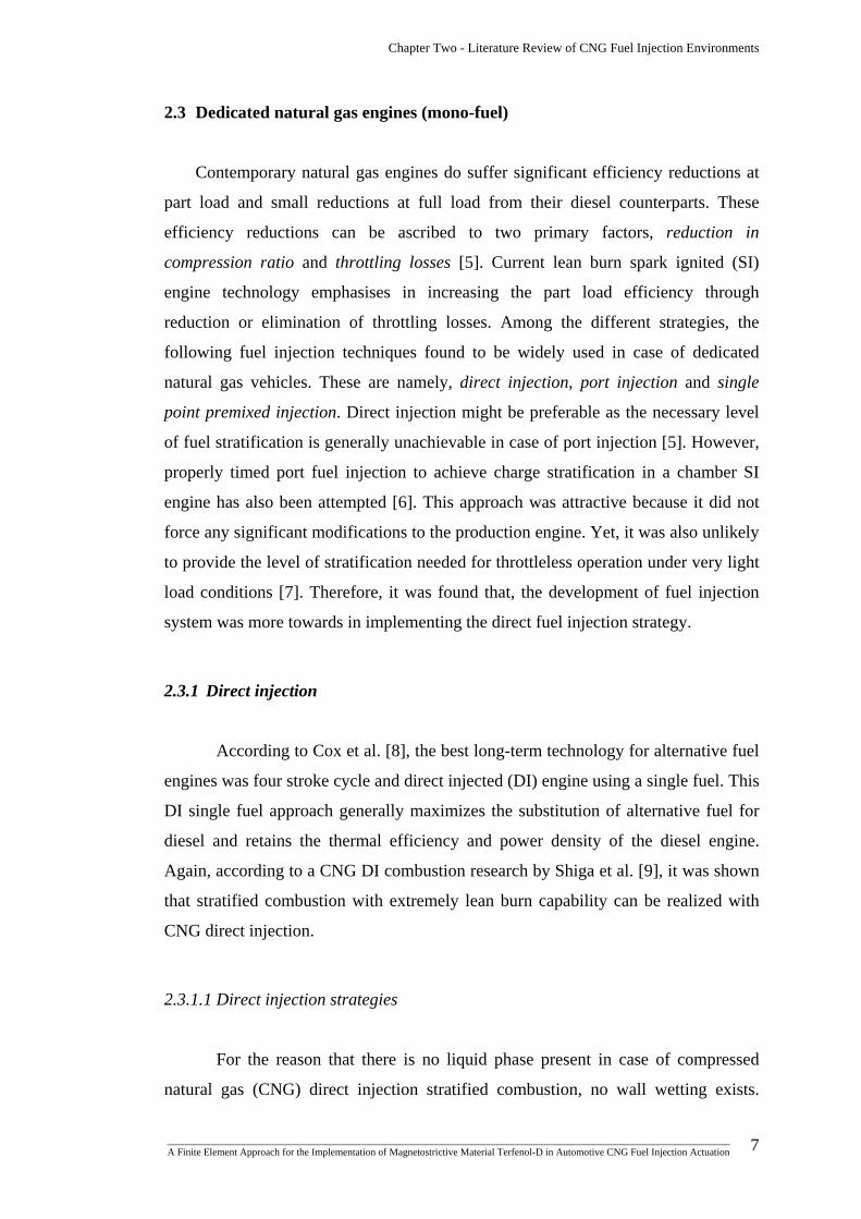
2.3 Dedicated natural gas engines (mono-fuel)
Contemporary natural gas engines do suffer significant efficiency reductions at
part load and small reductions at full load from their diesel counterparts. These
efficiency reductions can be ascribed to two primary factors, reduction in
compression ratio and throttling losses [5]. Current lean burn spark ignited (SI)
engine technology emphasises in increasing the part load efficiency through
reduction or elimination of throttling losses. Among the different strategies, the
following fuel injection techniques found to be widely used in case of dedicated
natural gas vehicles. These are namely, direct injection, port injection and single
point premixed injection. Direct injection might be preferable as the necessary level
of fuel stratification is generally unachievable in case of port injection [5]. However,
properly timed port fuel injection to achieve charge stratification in a chamber SI
engine has also been attempted [6]. This approach was attractive because it did not
force any significant modifications to the production engine. Yet, it was also unlikely
to provide the level of stratification needed for throttleless operation under very light
load conditions [7]. Therefore, it was found that, the development of fuel injection
system was more towards in implementing the direct fuel injection strategy.
2.3.1 Direct injection
According to Cox et al. [8], the best long-term technology for alternative fuel
engines was four stroke cycle and direct injected (DI) engine using a single fuel. This
DI single fuel approach generally maximizes the substitution of alternative fuel for
diesel and retains the thermal efficiency and power density of the diesel engine.
Again, according to a CNG DI combustion research by Shiga et al. [9], it was shown
that stratified combustion with extremely lean burn capability can be realized with
CNG direct injection.
2.3.1.1 Direct injection strategies
For the reason that there is no liquid phase present in case of compressed
natural gas (CNG) direct injection stratified combustion, no wall wetting exists.
_______________________________________________________________________________________________________________ A Finite Element Approach for the Implementation of Magnetostrictive Material Terfenol-D in Automotive CNG Fuel Injection Actuation
7

Chapter Two - Literature Review of CNG Fuel Injection Environments
Thus, comparing with the gasoline direct-injection engine, a smaller excessively fuel
rich volume can be expected. Furthermore, a greater charging efficiency could be
achieved than that of a port injection type or gas mixer type CNG engine because the
fuel can be injected after closing the intake valve [10]. However, some pressure
enhancement devices might be necessary to inject the fuel into a high-pressure
cylinder from the CNG storage when its pressure becomes lower than the required
injection pressure.
(a)
(b)
Figure 2.1: Arrangements of the fuel injectors and the spark gap [9]; (a)
opposed and single injection, spark gap at centre and halfway between
centre and wall, and (b) parallel injection with spark gap at centre.
As shown in figure 2.1, for a centrally positioned spark gap, the two injectors
are generally set at two different locations generating greater mixing between the gas
_______________________________________________________________________________________________________________ A Finite Element Approach for the Implementation of Magnetostrictive Material Terfenol-D in Automotive CNG Fuel Injection Actuation
8
Chapter Two - Literature Review of CNG Fuel Injection Environments
fuel, air and the combustion products due to the mutual impingement of the gas
which would result in better utilization of air and internal EGR. The injector
locations are cited as opposed injection and parallel injection as shown in figure 2.1
(a)-(b), respectively. In single injection strategy, the spark gap is generally set
halfway between the centre and the sidewall (near the injector tip) and the fuel is
injected through the injector closer to the gap [9].
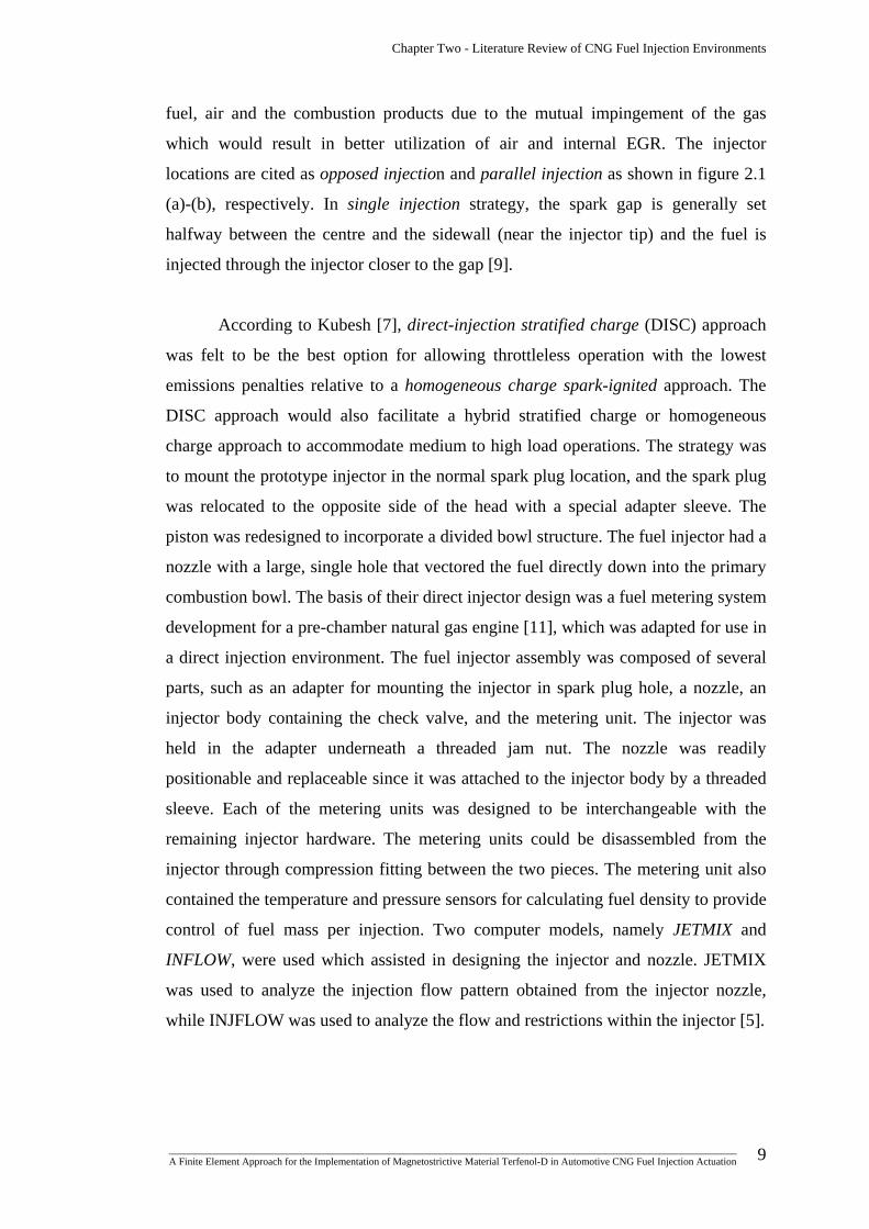
According to Kubesh [7], direct-injection stratified charge (DISC) approach
was felt to be the best option for allowing throttleless operation with the lowest
emissions penalties relative to a homogeneous charge spark-ignited approach. The
DISC approach would also facilitate a hybrid stratified charge or homogeneous
charge approach to accommodate medium to high load operations. The strategy was
to mount the prototype injector in the normal spark plug location, and the spark plug
was relocated to the opposite side of the head with a special adapter sleeve. The
piston was redesigned to incorporate a divided bowl structure. The fuel injector had a
nozzle with a large, single hole that vectored the fuel directly down into the primary
combustion bowl. The basis of their direct injector design was a fuel metering system
development for a pre-chamber natural gas engine [11], which was adapted for use in
a direct injection environment. The fuel injector assembly was composed of several
parts, such as an adapter for mounting the injector in spark plug hole, a nozzle, an
injector body containing the check valve, and the metering unit. The injector was
held in the adapter underneath a threaded jam nut. The nozzle was readily
positionable and replaceable since it was attached to the injector body by a threaded
sleeve. Each of the metering units was designed to be interchangeable with the
remaining injector hardware. The metering units could be disassembled from the
injector through compression fitting between the two pieces. The metering unit also
contained the temperature and pressure sensors for calculating fuel density to provide
control of fuel mass per injection. Two computer models, namely JETMIX and
INFLOW, were used which assisted in designing the injector and nozzle. JETMIX
was used to analyze the injection flow pattern obtained from the injector nozzle,
while INJFLOW was used to analyze the flow and restrictions within the injector [5].
_______________________________________________________________________________________________________________ A Finite Element Approach for the Implementation of Magnetostrictive Material Terfenol-D in Automotive CNG Fuel Injection Actuation
9

Chapter Two - Literature Review of CNG Fuel Injection Environments
2.3.1.2 Timings of fuel injection and ignition
For a CNG direct injection combustion study by Shiga et al. [9], the ignition
timing was fixed at 80 ms from the start of compression for all conditions and the
fuel injection timing was varied to ensure stable ignition. The injection timing for
twin injectors was set at 60 ms from the start of compression when the equivalence
ratio was greater than or equal to 0.6. Then again, the injection timing for a single
injector was set at 50 ms from the start of compression when the equivalence ratio
was greater than or equal to 0.6. However, when the equivalence ratio was less than
0.6, the injection timing was adjusted to give the best ignitability for the two kinds of
twin injection and the single injection.
2.3.1.3 Fuel injector
Precisely controlled flow of fuel vapour happens to be the focus of injector
design. Fuel injectors that utilise control valves that are opened and closed by
electrical solenoids, are widely used for injecting fuel into internal combustion
engines. In such devices, the actuating parts are subject to considerable impact forces
causing wear even in most highly durable materials. Then again, when the fuel is
gaseous, lubrication and viscous damping could not be afforded. Thus, design
requirements for gaseous fuel injectors involve self-lubrication, impact damping and
enlarged injector orifice size.
According to the study by Liu et al. [12], a higher injector component life
was ensured by fabricating the ball valve and introducing motion stops for the
reciprocating armature. The surface against which the armature slides was also
fabricated from a highly durable, low friction, impact cushioning, resilient plastic
material. Furthermore, the ball valve was placed above the armature and its seat so
that the ball was normally seated in its closed position and was driven to the open
position by the armature to minimize the inertia effects at closing. Basically, when
the coil was energized, the armature was driven upward against the valve end surface
which in turn opened the valve. With the coil energized, the upper surface of the
armature was put against the stop member on the bottom surface of the inner housing
_______________________________________________________________________________________________________________ A Finite Element Approach for the Implementation of Magnetostrictive Material Terfenol-D in Automotive CNG Fuel Injection Actuation
10
Chapter Two - Literature Review of CNG Fuel Injection Environments
which limited the upward travel. When not energised, the spring forced the ball and
the armature downward to a closed position.
2.3.1.4 Injector driver
In case of direct injection, two types of injector drivers were mostly found to
be used; these are peak hold drivers and saturated drivers. The saturated and peak
hold drivers generally designed for high and low impedance injectors respectively
[12].
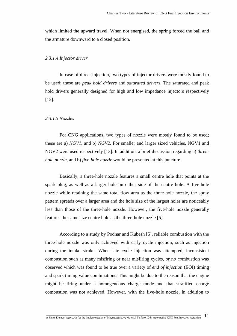
2.3.1.5 Nozzles
For CNG applications, two types of nozzle were mostly found to be used;
these are a) NGV1, and b) NGV2. For smaller and larger sized vehicles, NGV1 and
NGV2 were used respectively [13]. In addition, a brief discussion regarding a) three-
hole nozzle, and b) five-hole nozzle would be presented at this juncture.
Basically, a three-hole nozzle features a small centre hole that points at the
spark plug, as well as a larger hole on either side of the centre hole. A five-hole
nozzle while retaining the same total flow area as the three-hole nozzle, the spray
pattern spreads over a larger area and the hole size of the largest holes are noticeably
less than those of the three-hole nozzle. However, the five-hole nozzle generally
features the same size centre hole as the three-hole nozzle [5].
According to a study by Podnar and Kubesh [5], reliable combustion with the
three-hole nozzle was only achieved with early cycle injection, such as injection
during the intake stroke. When late cycle injection was attempted, inconsistent
combustion such as many misfiring or near misfiring cycles, or no combustion was
observed which was found to be true over a variety of end of injection (EOI) timing
and spark timing value combinations. This might be due to the reason that the engine
might be firing under a homogeneous charge mode and that stratified charge
combustion was not achieved. However, with the five-hole nozzle, in addition to
_______________________________________________________________________________________________________________ A Finite Element Approach for the Implementation of Magnetostrictive Material Terfenol-D in Automotive CNG Fuel Injection Actuation
11

Chapter Two - Literature Review of CNG Fuel Injection Environments
stable combustion in the early cycle injection mode, late cycle injection over a
specific range of EOI and spark-timing combinations also yielded stable combustion.
2.3.2 Stratified charge combustion
It is necessary to stratify the fuel-air charge so that an ignitable mixture can be
achieved near the spark plug at the time of ignition in order to achieve throttleless SI
operation over an entire engine operating range. Some feasible methods to
accomplish this requirement generally include, a) port injection open chamber
combustion approach, b) pre-chamber combustion approach, and c) direct injection
open chamber approach.
As mentioned earlier, port fuel injection open chamber combustion would be
attractive from the perspective of not forcing significant modifications to the
production engine. However, this approach was unlikely to provide the level of
stratification needed for throttleless operation at significant light load conditions.
Although a great deal of work has been done using the prechamber combustion
approach with natural gas in order to achieve extremely low emissions and high
efficiency, it was found that in order to achieve throttleless operation over the entire
operating range, a much larger prechamber, such as 10% or more of the main
chamber volume would be required. Research experiences with engines having
prechambers this large showed that these engines suffered significant emissions
penalties [5]. For this reason, a traditional prechamber approach was determined to
be inappropriate for several engine applications.
Considering these inconveniences, the DISC approach was felt to be the best
option for allowing throttleless operation resulting in high efficiency with the lowest
emissions penalties relative to a homogeneous charge SI approach. This approach
also accommodated the transition into the traditional homogeneous charge approach,
or a hybrid stratified charge and homogeneous charge approach for medium to high
load operation. For this reason, the DISC approach seemed to be the focus of the
stratified charge combustion system development effort [5,7].
_______________________________________________________________________________________________________________ A Finite Element Approach for the Implementation of Magnetostrictive Material Terfenol-D in Automotive CNG Fuel Injection Actuation
12

Chapter Two - Literature Review of CNG Fuel Injection Environments
2.4 Compressed natural gas in diesel environment
Generally, diesel cycle engine utilizes natural gas according to two following
ways, a) with diesel pilot-ignition, and b) using hot surface or glow plug ignition.
2.4.1 Pilot ignited high pressure direct injection of natural gas
Diesel cycle engine with diesel pilot ignition was an effort to reproduce the
diesel combustion cycle with natural gas. In this technology, a number of pilot diesel
sprays provided multiple ignition sites for the directly injected natural gas. As an
ignition source, only a small quantity of diesel pilot was found to be used, such as
from 2% to 5% at high loads, where the gas injection pressure being roughly between
19 and 25 MPa. Some major advantages of this technology included retention of the
efficiency of the diesel platform, maintenance of torque capability of the base diesel
engine, resistance to knocking at the presence of natural gas of varying qualities and
reduction in NOx, PM and CO2 emissions compared to the diesel baseline [14].
2.4.1.1 Diesel pilot injection strategy
According to a study regarding this technology yielded that the original diesel
injector was replaced by a new common rail type injector capable of injecting a small
quantity of pilot diesel fuel and a main charge of natural gas at the end of
compression stroke. Each injector incorporated two solenoid controlled valves, each
controlling the injection timing and the metering of one of the fuel to the combustion
chamber. A diesel pump provided diesel fuel to a rail at a pressure of approximately
25 MPa. Natural gas was supplied to a parallel rail at the same pressure. The rails
were balanced with a dome-loaded regulator to minimize leakage of one fuel into the
other within the injector. The pilot quantity remained roughly constant independently
from the load and varied between 9% and 2.4% when the load increased from 20% to
100% [14]. Figure 2.2 depicts the general working principle of diesel pilot ignition
with CNG direct injection.
_______________________________________________________________________________________________________________ A Finite Element Approach for the Implementation of Magnetostrictive Material Terfenol-D in Automotive CNG Fuel Injection Actuation
13

Chapter Two - Literature Review of CNG Fuel Injection Environments
Figure 2.2: Schematic of diesel pilot
ignition with natural gas DI.
2.4.2 Direct injection with hot surface ignition
Direct injection with hot-surface ignition technology was found to be an
attempt to provide some significant benefits, such as diesel-like efficiency and torque
with low emission, while simplifying the fuel injection system. This technology also
offered single refuelling step and potential for improved emissions as no diesel fuel
was used. Also according to Fukuda et al. [15], directly injected natural gas can be
successfully ignited by glow plugs.
2.4.2.1 Hot surface ignition strategy
The basis of glow plug ignition is the initiation of combustion by heat transfer
from a high temperature surface in excess of 1200°C [16-22]. A hydraulically driven
compressor is generally utilized to deliver high pressure CNG to common-rail
injectors at 20 to 25 MPa. A hydraulic pump is generally installed instead of the
original diesel pump, which could either be a common rail or a pump line nozzle
type. A spool valve generally controls the flow of hydraulic fluid to and from the
pump and compressor tubes. A reservoir and optional hydraulic cooler are generally
included also. The engine controller usually has the task to monitor and control the
injector driver, glow plug driver and the compressor. The injector is generally based
_______________________________________________________________________________________________________________ A Finite Element Approach for the Implementation of Magnetostrictive Material Terfenol-D in Automotive CNG Fuel Injection Actuation
14

Chapter Two - Literature Review of CNG Fuel Injection Environments
upon direct actuation of a gas needle. In this case, a magnetostrictive actuator could
be the best option due to its high durability and simple construction. Furthermore, the
hydraulic compressor has the task to compress natural gas from the main tank,
providing the ability to remotely mount the compressor away from the engine.
Basically, the initial ignition occurs in the thin layer of the glow plug where
the air/fuel mixture reaches ignition temperature. The flame propagation generally
starts from the surface of the glow plug. Special shields around the glow plug are
employed to limit cooling due to the air and CNG jet flow fields. Intake airflow,
particularly at high speeds, and the high-speed CNG jet usually have a pronounced
effect on cooling of the surface of the glow plug. However, this is significantly
critical as excessive cooling requires higher power levels and eventually shortens the
life of the glow plug. A sample glow plug ignition configuration is depicted in figure
2.3.
Injector Glow plug
Figure 2.3: Glow plug ignition.
It was found that, the foremost challenge of diesel pilot ignition was to
develop an injection system that would provide both high-pressure gas and pilot
diesel fuel. Thus, the necessities exist for a high-pressure gas injector or a combined
injection valve, which would inject both the main natural gas charge and the pilot
diesel with a high-pressure gaseous fuel supply. However, for hot surface or glow-
plug ignition, challenges similar to the direct injection spark ignited engines are to be
expected, since the right mixture has to be developed before the ignition at a wide
range of loads and speeds. In addition, continuous operation of the glow plugs at
_______________________________________________________________________________________________________________ A Finite Element Approach for the Implementation of Magnetostrictive Material Terfenol-D in Automotive CNG Fuel Injection Actuation
15

Chapter Two - Literature Review of CNG Fuel Injection Environments
higher temperature is yet another challenge of this technology. These challenges
were confirmed to various extents by several researchers that have been active in this
area, such as Caterpillar researchers [8,23,24], Mitsu [25], Shioji et al. [26] and
Bartunek and Hilger [27].
2.4.3 Dual-fuel diesel engine with induced natural gas
The operating range of a lean premixed compression ignition engine is
limited to higher excess air ratios because of the difficulties with both control of
ignition timing and knocking, although smokeless and ultra low NOx combustion has
been established with this technique [28-30]. A dual-fuel diesel engine, where an
induced natural gas acts as the main fuel with resistance to self-ignition and a small
quantity of diesel acts as the ignition source, has got excellent prospects to control
ignition timing and to realize the formation of rich and lean biform mixture
composition [31-33]. It eventually avoids near stoichiometric and extremely over-
rich regions. Furthermore, this technique helps to suppress NOx formation without
smoke increase when the overall excess air ratio approaches the stoichiometric.
However, knocking and misfiring might be some problems associated with it when
the percentage of inducted fuel is increased. According to a research by Ogawa et al.
[34] have established smokeless and ultra low NOx combustion without knocking
over a wide operating range in such a dual-fuel engine. At several IMEP conditions,
they investigated the optimizations of the combustion chamber shape and operating
factors, including exhaust gas recirculation (EGR) and intake air throttling.
2.4.3.1 Dual-fuel diesel engine with induced NG strategy
In this technique, natural gas is continuously induced into an intake manifold
upstream from the cylinder head. Furthermore, a small amount of conventional diesel
fuel is directly injected into the combustion chamber to act as the ignition source
from a common rail fuel injection system, as shown in figure 2.4. A lean quasi-
homogenous mixture is generally formed with induced natural gas in the combustion
chamber.
_______________________________________________________________________________________________________________ A Finite Element Approach for the Implementation of Magnetostrictive Material Terfenol-D in Automotive CNG Fuel Injection Actuation
16

Chapter Two - Literature Review of CNG Fuel Injection Environments
(a)
(b)
Figure 2.4: Concept of biform mixture formation in different piston cavity space in a
dual-fuel engine [34]; (a) Diesel fuel injection at 60° CA BTDC, and (b) Biform
mixture formation at end of compression.
According to a study performed by Ogawa et al. [34], the injection timing of
the diesel fuel was set at 60° CA BTDC, which was relatively an earlier timing to
prevent an extremely rich mixture and smoke formation. It was also expected that a
slightly richer than stoichiometric mixture was to be formed in the lower part of the
cavity, and a leaner mixture in the upper part. The fuel injection nozzle had four
holes typically 0.21 mm in diameter, while the spray hole cone angle was 40°. A
throttle valve was installed in the intake manifold to control the overall excess air
ratio. The piston had an interchangeable piston crown and cavity allowing the use of
two different piston cavity shapes, namely divided and ordinary toroidal cavity. The
piston cavity was divided by a lip in the sidewall, as shown in figure 2.4, which was
suitable to confine diesel fuel into the lower part of the cavity, and this suppressed
knocking just after ignition. The results of their experiments showed that a
combination of the divided cavity, exhaust gas recirculation and intake air throttling
was effective to simultaneously eliminate knocking and reduce total hydrocarbon
(THC) and NOx over a wide IMEP range.
_______________________________________________________________________________________________________________ A Finite Element Approach for the Implementation of Magnetostrictive Material Terfenol-D in Automotive CNG Fuel Injection Actuation
17

Chapter Two - Literature Review of CNG Fuel Injection Environments
2.4.4 Natural gas combustion assisted with gas-oil in a diesel engine
For the purposes of reducing NOx and smoke, and to achieve significant
improvement of trade-off between smoke and NOx without deteriorating fuel
consumption, natural gas is generally charged homogeneously into the intake air and
is burned by igniting a small amount of gas oil injection. According to a study by
Ishida et al. [35], a high burning rate of natural gas resulted in shortening the
combustion duration, subsequently leading to lower fuel consumption. Generally, if
the burning rate of natural gas is too high, it results in increase of NOx. In contrast,
too low burning rate results in increases of fuel consumption and THC. By raising
the intake charge temperature up to 120°C, which increased the burning rate of
natural gas, they managed to drastically improve the fuel consumption and THC.
Increase in NOx due to high burning rate of natural gas at the high load was mended
by lowering the intake charge temperature below 60°C, which suppressed the
burning rate of natural gas. Besides, high EGR rate showed suppression effect on the
burning rate at the high load. However, the burning rate was found to be hardly
affected by EGR at the low load. Eventually, NOx was reduced effectively by EGR
without deteriorating fuel consumption, which was thought to be due to the water
content brought by EGR as well as the decrease in oxygen concentration of the
intake charge.
2.5 Compressed natural gas in gasoline environment
Due to some of its favourable physio-chemical properties, CNG appears to be
an excellent fuel for the spark ignition (SI) engine. Moreover, SI engines can be
converted to CNG operation quite effortlessly as a second fuelling system.
2.5.1 CNG as an alternative fuel for a retrofitted gasoline vehicle
The development of new dedicated natural gas vehicle (NGV) is very difficult
within a diminutive time, as it requires new ignition, combustion, injection and
engine control system. Therefore, after market conversion or retrofitting happens to
be the realistic way to increase CNG based bi-fuel vehicles [36]. As a consequence,
_______________________________________________________________________________________________________________ A Finite Element Approach for the Implementation of Magnetostrictive Material Terfenol-D in Automotive CNG Fuel Injection Actuation
18

Chapter Two - Literature Review of CNG Fuel Injection Environments
in order to satisfy customer demand, vehicle manufacturers are more interested in
converting gasoline engines into bi-fuel ones rather than producing new-dedicated
NGVs [37]. Also from a study, it was found that, on average retrofitted CNG engine
reduces CO by around 80%, CO2 by 20% and HC by 50% compared to gasoline [36].
However, retrofitted NGV engine produce about 10–15% less power than the
same engine fuelled by gasoline [38-40]. Jones and Evans [41] measured a total
power loss of approximately 15% and efficiency drop of 5% when changing from
gasoline to CNG. 10% loss of power was attributed due to reduction in the inhaled
energy and the remaining 5% to the lower burning velocity of CNG compared to
gasoline. Aslam et al. [36] also concluded from their study that retrofitted CNG
engine produces round 16% less brake mean effective pressure (BMEP) and
consumes 17–18% less brake specific fuel consumption (BSFC), or consumes an
average of 1.65 MJ less energy per kWh at wide open throttle (WOT) condition with
CNG compared to gasoline. In another comparative study of performance and
exhaust emissions by Evans and Blaszczyk [42], it was also observed that the BMEP
and BSFC were both 12% lower with CNG at WOT condition. Another study by
Hamid and Ahmad [43] presented a comparison of the NGV and gasoline base
engine performance where they found the volumetric efficiency of the NGV engine
was reduced by about 15% and overall performance lowered by circa 9% at
maximum torque and maximum power conditions.
2.5.2 Natural gas direct injection in spark ignited Otto cycle engine
This technique is similar or equivalent to some extents with gasoline direct
injection (GDI). It provides an efficiency enhancement by reducing throttling losses.
This is generally achieved by the precise control over amount of fuel and injection
timings that are varied according to the load conditions. Basically, the engine
management system continuously chooses between three different modes of
combustion - ultra lean burn combustion, stoichiometric combustion and high power
output mode. In addition, this method avoids the volumetric efficiency loss that is
caused by the presence of low-density natural gas in the intake manifold. But several
challenges regarding the control of NOx and hydrocarbon emissions are evident, as
_______________________________________________________________________________________________________________ A Finite Element Approach for the Implementation of Magnetostrictive Material Terfenol-D in Automotive CNG Fuel Injection Actuation
19
Chapter Two - Literature Review of CNG Fuel Injection Environments
in the case of GDI engines mentioned in many research works by Southwest
Research Institute [5,7], Goto and Sato [44,45] from Japanese traffic Safety and
Nuisance Research Institute, and Arcoumanis et al [46] from Imperial College.
2.6 Compressed natural gas and hydrogen
A possible approach for meeting future emission regulations with current natural
gas engine design is to blend hydrogen with compressed natural gas (CNG). This
would allow leaner air/fuel ratio and retarded spark timing [47]. Despite its low
energy density, hydrogen can improve engine performance at very lean engine
operation, because it releases more energy per unit oxygen consumed. Moreover, the
increased flame speed and lean combustion ability of hydrogen would enhance the
combustion efficiency significantly. Altogether, the lean air/fuel ratio and retarded
timing can reduce NOx considerably without the use of exhaust gas after-treatment
equipments.
Early research on hydrogen enrichment was focused on fuels such as gasoline
and iso-octane [48,49]. These experiments established the effectiveness of hydrogen
in extending the lean operating limit as well as reducing NOx emissions and
increasing thermal efficiency. Later studies of hydrogen enrichment have focused on
natural gas utilizing lean-burn, spark-ignited (SI) engines [50-53]. According to a
study undertaken by National Renewable Energy Laboratory (NREL), USA [5],
which involved H/CNG blend for transit buses, it was concluded that minor engine
and vehicle hardware modifications were required for the 20/80 H/CNG operation.
The modifications were the addition of a new fuel mass flow rate sensor and
additional vehicle fuel tanks. However, the fuel economy was reduced by about 12%
relative to the CNG operation on a diesel gallon equivalent basis.
2.6.1 Hydrogen assisted jet ignition (HAJI)
Hydrogen assisted jet ignition (HAJI) is commonly used to achieve reliable
combustion and low NOx emissions. It is a system developed by Transport Energy
Group, University of Melbourne [54], which replaces the spark plug in a
_______________________________________________________________________________________________________________ A Finite Element Approach for the Implementation of Magnetostrictive Material Terfenol-D in Automotive CNG Fuel Injection Actuation
20

Chapter Two - Literature Review of CNG Fuel Injection Environments
conventional spark ignition engine and virtually eliminates the lean limit. HAJI
primarily consists of, a) a small prechamber which is approximately 0.7% of the
TDC main chamber volume, b) a hydrogen injector, and c) a spark plug.
2.6.1.1 HAJI strategy
In this technique, Hydrogen is generally injected into the pre-chamber prior to
ignition. Stable and repeatable ignition is guaranteed by the wide flammability limits
of H2. The increased pressure from combustion forces the ignited hydrogen gas
through a number of orifices into the main chamber. The presence of highly reactive
partial products and turbulence generally causes the resulting jets to have an energy
level at least two orders of magnitude higher than that of a spark [55]. In the main
chamber, the fuel is then ignited by these jets in a stable and reliable manner, as
shown in figure 2.5.
Exhaust Valve
Inlet Valve
Hydrogen Injector
Pre-chamber
Spark Plug
Main Combustion Chamber
Figure 2.5: Schematic of hydrogen assisted jet ignition.
A HAJI-equipped engine could be run as lean as relative air/fuel ratio, λ = 5
resulting in an Ultra Low Emissions Vehicle (ULEV), without the need for complex
and expensive exhaust after treatment. An additional benefit is that the work per
cycle could be reduced to no load quantities by simply increasing the air/fuel ratio.
Since there is effectively neither a lean limit nor the need for a catalytic converter,
_______________________________________________________________________________________________________________ A Finite Element Approach for the Implementation of Magnetostrictive Material Terfenol-D in Automotive CNG Fuel Injection Actuation
21

Chapter Two - Literature Review of CNG Fuel Injection Environments
this eventually results in the reduction of pumping losses that has been estimated to
improve efficiency by around 20% [56].
Current research work regarding a HAJI-equipped engine is focused on
reducing the hydrocarbon (HC) emissions. According to Lawrence [57], these HC
emissions were largely due to quench and crevice. As the air/fuel ratio was increased,
the proportion of total emissions contributed by crevice was decreased even though
the absolute quantity of crevice emissions increased. In contrast, an increased air/fuel
ratio resulted in increased quench emissions both proportionally and absolutely. This
was attributed to quench being more strongly influenced by a reduction of peak
temperatures than crevice. In order to reduce both crevice and quench emissions, fuel
stratification facilitated by direct injection was suggested. From another study by
Wang and Watson [54], it was concluded that negligible levels of CO and NOx
emissions were preserved with the introduction of CNG direct injection while fuel
stratification was minimally achieved by direct injection. However, the reduction in
exhaust HC was mainly attributed to a reduction in crevice emissions. They also
recommended that in order to get better fuel stratification, a dual opposing injection
strategy, either with or without induced swirl, might be helpful.
2.7 Summary of chapter two
Although present alternative fuel technologies might be sufficient to meet the
current emission reduction legislations, continuous in depth research regarding new
and improved fuel injection systems are quite indispensable to meet any future
emission standards. In this context, due to their enormous potential regarding sensing
and actuating capabilities, smart materials such as magnetostrictive (MS),
piezoelectric and magnetorheological fluid (MRF) possess tremendous prospect in
developing different types of actuator design concepts [58]. The following chapters
will focus on designing a compressed natural gas fuel injector utilizing such a
material as an actuator in order to step towards a more efficient fuel injection system
compared to the traditional solenoid injection one. A concise and inclusive overview
of the highlighted research process of this chapter is shown in figure 2.6.
_______________________________________________________________________________________________________________ A Finite Element Approach for the Implementation of Magnetostrictive Material Terfenol-D in Automotive CNG Fuel Injection Actuation
22

Chapter Two - Literature Review of CNG Fuel Injection Environments
5 FEMM Magnetic Field Simulation
6 ANSYS Electromagnetic Verification
Dedicated NGV - Direct injection - Stratified charge combustion
Diesel environment - Pilot ignition - Hot surface ignition - Duel-fuel with induced NG
Gasoline environment - SI engine - Retrofitted
Hydrogen assisted - H/CNG blend - HAJI
CNG fuel injection environments
Introduction - Compressed natural gas - CNG properties
1
Legend: Research task Resource Sequence
Prototype Fuel Injector Design
Literature review of smart materials 3
Summary Necessity for innovative and improved fuel injection strategies to meet future emission
standards
4
8 Research Outcome
7 FLUENT Fuel Flow Rate Prediction
2 Literature Review
- CNG fuel injection
Point of Departure
Figure 2.6: Summary of the research process in chapter two.
_______________________________________________________________________________________________________________ A Finite Element Approach for the Implementation of Magnetostrictive Material Terfenol-D in Automotive CNG Fuel Injection Actuation
23

CHAPTER THREE
LITERATURE REVIEW
OF
SMART MATERIALS
Chapter Three - Literature Review of Smart Materials
3.1 Introduction
Materials that possess the ability to perform both sensing and actuating
functions are generally defined as “smart” [59]. Hence, magnetostriction or
piezoelectricity is the changing of physical dimensions of materials, such as most
ferromagnetic materials, piezo-crystals and certain ceramic material, in response to
changing its magnetization. In other words, a magnetostrictive or piezoelectric
material will change shape when it is subjected to a magnetic field or an externally
applied voltage. A passively smart material has the ability to respond to
environmental conditions in a useful manner showing a distinction from an actively
smart material in that there are no external fields, forces or feedback systems used to
enhance its behavior.
This chapter will highlight different aspects of smart materials, especially in
case of magnetostrictive material, mechanism of magnetostriction and their prospect
for fuel injection actuation. In addition, a detailed investigation regarding the
material and magnetic properties of magnetostrictive material Terfenol-D will also be
performed. Furthermore, some discussions regarding the production and non-linear
characteristics of piezoelectric materials will also be presented.
3.2 Actuator Materials
Materials that show the highest known magnetostriction are those of cubic
laves phase iron alloys containing the rare earth elements Dysprosium, Dy, or
Terbium, Tb; DyFe2, and TbFe2. However, these materials have tremendous magnetic
anisotropy which requires a very large magnetic field to drive the magnetostriction.
Noting that these materials have anisotropies in opposite directions, Clark [60] and
his co-workers at NSWC-Carderock prepared alloys containing Fe, Dy, and Tb which
are generally stoichiometric of the form Tb Dyx 1-xFey (where y = 1.9 to 2) referred as
Terfenol-D. For example, Terfenol-D (Tb0.3 Dy0.7 Fe1.9), is capable of approximately
10 µm displacements for every 1 cm of length exposed to an approximately 500
Oersted magnetizing field.
_______________________________________________________________________________________________________________ A Finite Element Approach for the Implementation of Magnetostrictive Material Terfenol-D in Automotive CNG Fuel Injection Actuation
24

Chapter Three - Literature Review of Smart Materials
Also, Lead Zirconate Titanate ( 0<x<1) or PZT is a ferroelectric Pb[ZrxTi1-x]O3
ceramic perovskite material that shows a marked piezoelectric effect. Like
structurally similar lead scandium tantalate and barium strontium titanate, PZT
possess good prospects for manufacturing actuator devices due to lower material cost
and improved performance.
For typical transducer and actuator applications, Terfenol-D is the most
commonly used engineering magnetostrictive material [61] and in the case of fuel
injection actuation, it offers exquisite potential. Earlier alloys exhibited large
magnetostriction, but either at very large magnetic fields or at cryogenic
temperatures. Terfenol-D overcame the temperature difficulty by incorporating RFe2
microstructure which raised the Curie temperature above room temperature. The
necessary magnetic field was reduced by balancing the ratio of Terbium and
Dysprosium, two elements with oppositely signed magneto-crystalline anisotropy,
such that effective anisotropy of the compound was near zero at room temperature.
Since this time, Terfenol-D has become the foremost magnetostrictive material,
although research continues into new materials constantly [62].
In this context, Xie et al. [63] prepared well-aligned pseudosingle crystals of a
series of Terfenol-D using the Czochralski method by which grain-aligned rod can be
prepared in one relatively speedy operation. The effects of several parameters, which
included pulling rate, heat treatment and start material purity on the
magnetomechanical coupling factor (k33) of the samples, was investigated in their
work. Their grown Terfenol-D rods showed high k33 values without subsequent heat
treatment. Magnetomechanical coupling coefficients are further discussed in section
3.5.3.
Researchers recently investigated another material which is an iron/gallium
alloy termed Galfenol by its inventors at the Naval Surface Warfare Center (Clark et
al.). Studies performed with these alloys showed that magnetostriction peaked in
iron/gallium alloys at a volume fraction of 17% gallium. Single crystal Galfenol
exhibited magnetostriction on the order of 400 ppm at low applied fields. In
addition, unlike Terfenol-D, Galfenol is tough and may be machined and used in
devices where Terfenol-D may fracture. While the magnetostriction mechanism in _______________________________________________________________________________________________________________ A Finite Element Approach for the Implementation of Magnetostrictive Material Terfenol-D in Automotive CNG Fuel Injection Actuation
25
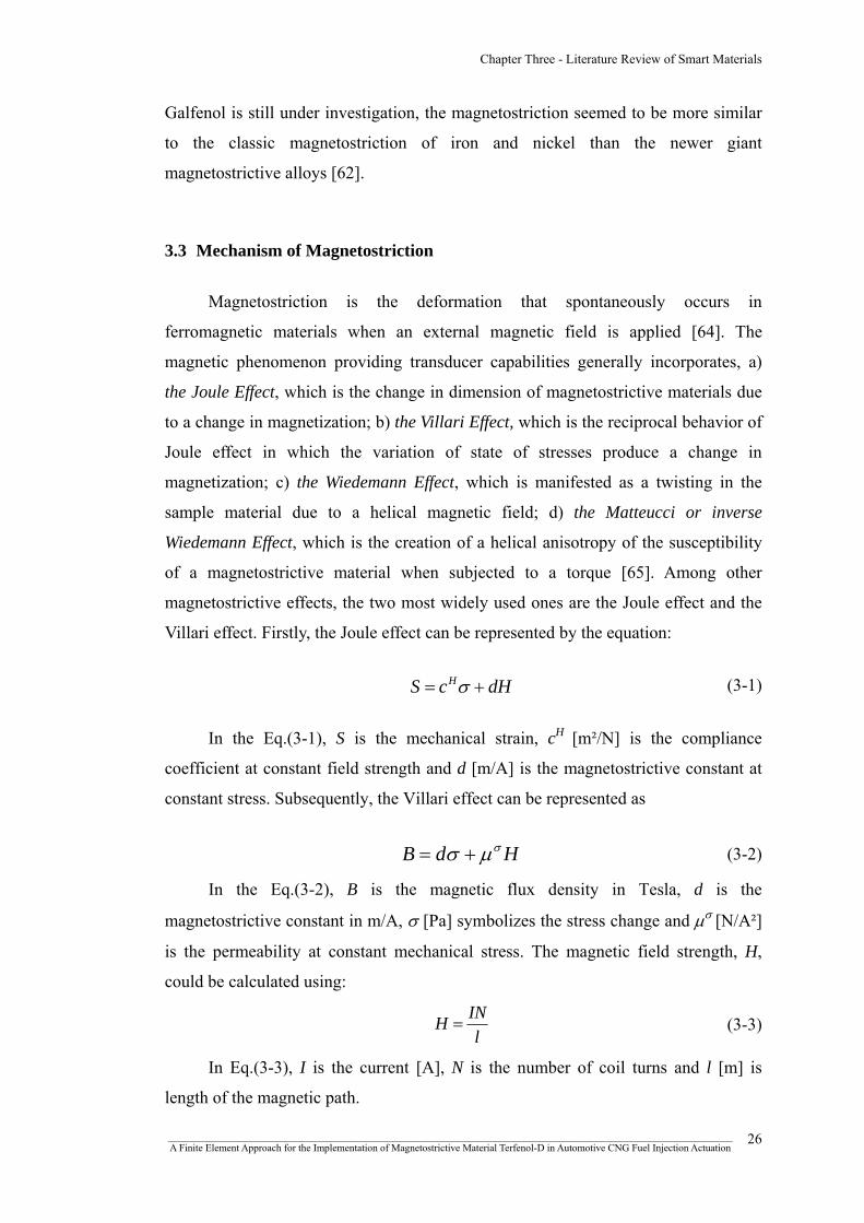
Chapter Three - Literature Review of Smart Materials
Galfenol is still under investigation, the magnetostriction seemed to be more similar
to the classic magnetostriction of iron and nickel than the newer giant
magnetostrictive alloys [62].
3.3 Mechanism of Magnetostriction
Magnetostriction is the deformation that spontaneously occurs in
ferromagnetic materials when an external magnetic field is applied [64]. The
magnetic phenomenon providing transducer capabilities generally incorporates, a)
the Joule Effect, which is the change in dimension of magnetostrictive materials due
to a change in magnetization; b) the Villari Effect, which is the reciprocal behavior of
Joule effect in which the variation of state of stresses produce a change in
magnetization; c) the Wiedemann Effect, which is manifested as a twisting in the
sample material due to a helical magnetic field; d) the Matteucci or inverse
Wiedemann Effect, which is the creation of a helical anisotropy of the susceptibility
of a magnetostrictive material when subjected to a torque [65]. Among other
magnetostrictive effects, the two most widely used ones are the Joule effect and the
Villari effect. Firstly, the Joule effect can be represented by the equation:
dHcS H += σ (3-1)
H
In the Eq.(3-1), S is the mechanical strain, c [m²/N] is the compliance
coefficient at constant field strength and d [m/A] is the magnetostrictive constant at
constant stress. Subsequently, the Villari effect can be represented as
HdB σμσ += (3-2)
In the Eq.(3-2), B is the magnetic flux density in Tesla, d is the
magnetostrictive constant in m/A, σ [Pa] symbolizes the stress change and μσ [N/A²]
is the permeability at constant mechanical stress. The magnetic field strength, H,
could be calculated using:
lINH = (3-3)
In Eq.(3-3), I is the current [A], N is the number of coil turns and l [m] is
length of the magnetic path.
_______________________________________________________________________________________________________________ A Finite Element Approach for the Implementation of Magnetostrictive Material Terfenol-D in Automotive CNG Fuel Injection Actuation
26
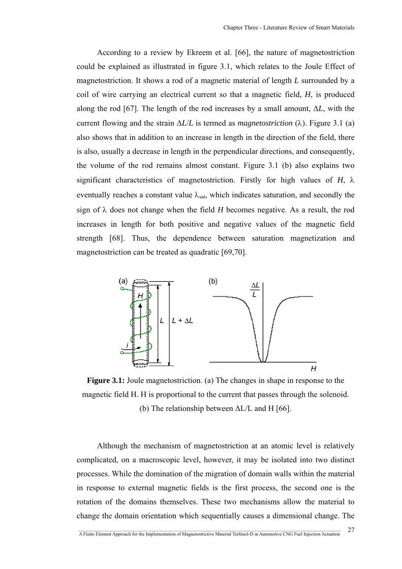
Chapter Three - Literature Review of Smart Materials
According to a review by Ekreem et al. [66], the nature of magnetostriction
could be explained as illustrated in figure 3.1, which relates to the Joule Effect of
magnetostriction. It shows a rod of a magnetic material of length L surrounded by a
coil of wire carrying an electrical current so that a magnetic field, H, is produced
along the rod [67]. The length of the rod increases by a small amount, ΔL, with the
current flowing and the strain ΔL/L is termed as magnetostriction (λ). Figure 3.1 (a)
also shows that in addition to an increase in length in the direction of the field, there
is also, usually a decrease in length in the perpendicular directions, and consequently,
the volume of the rod remains almost constant. Figure 3.1 (b) also explains two
significant characteristics of magnetostriction. Firstly for high values of H, λ
eventually reaches a constant value λsat, which indicates saturation, and secondly the
sign of λ does not change when the field H becomes negative. As a result, the rod
increases in length for both positive and negative values of the magnetic field
strength [68]. Thus, the dependence between saturation magnetization and
magnetostriction can be treated as quadratic [69,70].
Figure 3.1: Joule magnetostriction. (a) The changes in shape in response to the
magnetic field H. H is proportional to the current that passes through the solenoid.
(b) The relationship between ΔL/L and H [66].
Although the mechanism of magnetostriction at an atomic level is relatively
complicated, on a macroscopic level, however, it may be isolated into two distinct
processes. While the domination of the migration of domain walls within the material
in response to external magnetic fields is the first process, the second one is the
rotation of the domains themselves. These two mechanisms allow the material to
change the domain orientation which sequentially causes a dimensional change. The _______________________________________________________________________________________________________________ A Finite Element Approach for the Implementation of Magnetostrictive Material Terfenol-D in Automotive CNG Fuel Injection Actuation
27

Chapter Three - Literature Review of Smart Materials
re-orientation of magnetic domains can be represented schematically, as shown in
figures 3.2 and 3.3. In the region between 0 and 1, where the applied magnetic field
is small, the magnetic domains show almost no common orientation pattern.
However, depending on the way that the material was formed, there might be a small
amount of a common orientation pattern, which would show itself as a permanent
magnet bias. In addition, the resulting strain depends very much on how
homogeneous the base structure of the magnetostrictive material is, besides the
material formulation. Then, in the region 1–2, ideally there should be an almost
linear relationship between strain and magnetic field, which eventually makes it
easier to predict the behavior of the material. However, beyond point 2, the
relationship becomes non-linear again as a result of the fact that most of the magnetic
domains have become aligned with the magnetic field direction. The saturation effect
is predominant at point 3, which prevents further strain increase [71].
Figure 3.2: Graphical representation of
strain vs. magnetic field (idealized behaviour) [71].
Figure 3.3: Schematic of strain vs. magnetic field [71].
_______________________________________________________________________________________________________________ A Finite Element Approach for the Implementation of Magnetostrictive Material Terfenol-D in Automotive CNG Fuel Injection Actuation
28

Chapter Three - Literature Review of Smart Materials
During this stretching process, the cross-section of the material is reduced in
such a way that the volume is kept nearly constant or the volume change is so minute
that it can be neglected under normal operating conditions. Thus, the deformation can
be termed as isochoric. Again, applying a stronger magnetic field leads to stronger
and more definite re-orientation of increasingly more domains in the direction of
magnetic field and when all the magnetic domains have become aligned with the
magnetic field the saturation point is considered to be achieved. Thus, the basic
theme of magnetostriction remains that the rotation and movement of magnetic
domains causes a physical length change in the material.
Modern magnetostrictive materials, such as Terfenol-D, are often
manufactured as rods with residual magnetic fields nearly perpendicular to the rod
axis. This is due to the fact that domains in the material with magnetic fields already
aligned with the rod axis do not change in direction when an external magnetic field
is applied along the rod axis. Therefore, these domains do not contribute to the
magnetostriction. Accordingly, a rod which has domains aligned randomly will only
produce about two fifths of the maximum possible magnetostriction. Therefore it is
desirable to arrange all the domains to be aligned perpendicular to the rod axis [66].
Figure 3.4: Application of compressive load
to magnetostrictive materials [61].
Thus, in standard operations, magnetostrictive materials are mechanically
biased. For a positive magnetostrictive material such as Terfenol-D, which generally
consists of randomly oriented magnetic dipoles, a compressive load (σ) causes the
_______________________________________________________________________________________________________________ A Finite Element Approach for the Implementation of Magnetostrictive Material Terfenol-D in Automotive CNG Fuel Injection Actuation
29

Chapter Three - Literature Review of Smart Materials
orientation of these magnetic dipoles perpendicularly to the force, as shown in figure
3.4. This has the consequence of increasing the number of domains available for
reorientation due to external magnetic field (H), thus maximizing stroke [72].
3.4 Fuel Injection
3.4.1 Prospect for smart materials
The fuel systems for internal combustion engines are critically important to
meet the efficiency and emissions targets. A major motivation of engine research is to
increase fuel efficiency and to lower the pollution to the environment. In order to
improve efficiency and lower emissions, almost every step for improving control of
the combustion process depends on improvements in the fuel injection system.
Multiple fuel injections per combustion cycle can increase the fuel efficiency and
lower the NOx and particulate emissions. However, due to the present stroke speed
limitations of magnetic solenoid valves, multiple injections require the development
of high-speed actuators. Also, precision manufacturing processes are influential in
developing improved fuel injection systems. Focusing on the environmental
concerns, in order to minimize particulate emissions, the electronic fuel injectors
could operate at high pressures, such as about 20,000 psi [73]. To meet the emerging
emissions regulations, the fuel injection pressure is also likely to increase to as much
as 35,000 psi. This high-pressure fuel injection results in problems with wear and
abrasion of fuel injector plungers and erosion, wear, and fatigue of fuel injector
nozzles. In addition, low-sulfur fuels typically do not lubricate the fuel injector
components. Moreover, the individual components must fit together with clearances
sometimes smaller than 1 x 10⁻⁶ meters. Besides, control of the combustion process
requires precise control of the size, shape, and surface finish of the injector
components. In addition to new and improved materials, improved manufacturing
and inspection methods for the injector components are needed as well. Although a
single fuel injection event occurs in a brief fraction of a second, greater control of the
rate and timing of the injection event is necessary to improve the control of
combustion and resulting efficiency and emissions [73]. Pilot injection, for example,
has shown to reduce NOx by spreading out the combustion event over time which
reduces the maximum combustion temperature. Further reductions in NOx might be
_______________________________________________________________________________________________________________ A Finite Element Approach for the Implementation of Magnetostrictive Material Terfenol-D in Automotive CNG Fuel Injection Actuation
30

Chapter Three - Literature Review of Smart Materials
accomplished by spreading out the injection into several events, all of which must
occur within a very brief time. The current systems for reliably controlling multiple
injections are limited by the ability of mechanical and electronic systems to respond
precisely and quickly enough to provide the additional control of injection.
In this context, smart materials, such as piezoelectric and magnetostrictive
materials, offer the potential of better control of fuel injection. Due to lower
materials costs and performance, some of the candidate devices for these actuators
are lead zirconium titanate (PZT) [74]. Although multilayered PZT materials have
been studied and are favored for their low power consumption and high precision
control, a number of improvements and manufacturing methods for the materials are
yet to be explored. As a result, the current research at Oak Ridge National Laboratory
(ORNL) is directed towards developing a low cost multi-layer PZT actuator to be
used in fuel injectors [74]. Besides, several innovations regarding the fuel injector
actuator are currently under exploration with Terfenol-D as preferred actuator
materials.
3.4.2 Comparative discussion between conventional solenoid injection and
injection actuated by smart materials
Conventional method of actuating a fuel injector was by using an
electromagnetic solenoid arrangement, which was an insulated conducting wire
wound to form a tight helical coil within which a magnetic field was generated in a
direction parallel to the axis of the coil when current passed through the wire. When
the coil was energized, the resulting magnetic field exerted a force on a moveable
ferromagnetic armature located within the coil, in that way causing the armature to
move a needle valve into an open position in opposition to a force generated by a
return spring. The force exerted on the armature was proportional to the strength of
the magnetic field while the strength of the magnetic field depended on the number
of turns of the coil and the amount of current passing through the coil [75].
In the conventional fuel injector, as shown in figure 3.5, the point at which the
armature started to move varied primarily with factors such as the spring preload
_______________________________________________________________________________________________________________ A Finite Element Approach for the Implementation of Magnetostrictive Material Terfenol-D in Automotive CNG Fuel Injection Actuation
31

Chapter Three - Literature Review of Smart Materials
holding the injector closed, the friction and inertia of the needle, fuel pressure, eddy
currents in the magnetic materials, and the magnetic characteristics of the design.
The armature generally would not move until the magnetic force progresses to a level
high enough to overcome the opposing forces. Similarly, the needle would not return
to a closed position until the magnetic force decays to a low enough level for the
closing spring to overcome the fuel flow pressure and needle inertia. In a
conventional injector design, once the needle started actuating, it might continue to
accelerate until it collided with its respective end-stops. This would eventually result
in wear in the needle valve seat, needle bounce, and unwanted vibrations and noise
problems. Therefore, an improved fuel injector actuation method was a requirement
that would provide reduced noise, longer seat life, elimination of bounce and full
actuator force applied during the entire armature stroke [75].
(a)
(b)
Figure 3.5: Traditional fuel injector; (a) solenoid off, valve closed position; (b)
solenoid on, plunger movement and valve open position [76].
_______________________________________________________________________________________________________________ A Finite Element Approach for the Implementation of Magnetostrictive Material Terfenol-D in Automotive CNG Fuel Injection Actuation
32

Chapter Three - Literature Review of Smart Materials
Again, a piezoelectric actuator consisting of a stack of piezoceramic or
piezocrystal wafers bonded together to form a piezostack transducer, can convert
energy in an electric field into a mechanical strain in the piezoelectric material. The
piezostack might be attached to the mechanical member or needle performing a
similar function as the needle in the conventional injector. When the piezostack has a
high voltage potential applied across the wafers, the piezoelectric effect causes the
stack to change dimension, thereby opening the fuel injector. However, piezoelectric
transduction requires high voltages to generate a useful electric energy density and
hence a useful strain in the piezoelectric material [75]. Thus, the necessity still
existed for a fuel injector capable of operating on the magnetic equivalent of the
piezoelectric effect.
In this context, magnetostriction could play a significant role. To illustrate the
basic control operation of magnetostrictive transducers, we might consider the
configuration as shown in figure 3.6. The primary components of the actuator
generally consist of a cylindrical magnetostrictive rod, a wound wire solenoid, an
enclosing permanent magnet and a prestress mechanism. The rod is usually
constructed so that magnetic moments were primarily oriented perpendicular to the
longitudinal rod axis. The number of perpendicular moments and compression in the
rod could be further increased by the prestress mechanism. The application of current
to the solenoid then would produce a magnetic field which would cause the moments
to rotate so as to align with the field. The resulting strains and forces provide the
actuator with the capabilities for transduction. The capability for attaining
bidirectional strains and forces is usually provided by a magnetic bias generated by
either the surrounding permanent magnet or an applied DC current to the solenoid
[77].
_______________________________________________________________________________________________________________ A Finite Element Approach for the Implementation of Magnetostrictive Material Terfenol-D in Automotive CNG Fuel Injection Actuation
33

Chapter Three - Literature Review of Smart Materials
Figure 3.6: Cross section of a prototypical Terfenol-D magnetostrictive
transducer [77].
It is thus apparent, that the exploitation of such exquisite characteristics of
magnetostrictive materials, such as Terfenol-D, would unfold more design
opportunities for many precision control applications including fuel injector design.
3.5 Magnetostrictive Material Terfenol-D
3.5.1 Terfenol-D properties
The alloy formulation of Terfenol-D is composed of, “Ter” from Terbium, “Fe”
for iron, “NOL” as Naval Ordnance Laboratory and “D” from Dysprosium. Although
magnetostriction only occurs in a material at temperatures below the Curie
temperature, often the Curie temperature is below the temperature of the
surroundings which eventually causes the magnetostriction effect to have little
practical value [78]. In this context, in comparison with other magnetostrictive
materials, Terfenol-D (Tb0.3D0.7Fe1.9) possesses high strain, high Curie temperature,
high reliability or unlimited cycle life, high force, attractive controllability with high
power density and microsecond response time. Moreover, the elongation of the
Terfenol-D shaft is proportional to the applied magnetic field and the
magnetostriction is a reversible feature as without the magnetic field the shape of the
magnetostrictive material reverts to its original shape. All of these unique utilitarian
features make this material a potentially appropriate and enhanced alternative for
automotive fuel injection actuation compared with the traditional solenoid fuel
injection system. Terfenol-D was discovered by a research group led by A.E. Clark in
_______________________________________________________________________________________________________________ A Finite Element Approach for the Implementation of Magnetostrictive Material Terfenol-D in Automotive CNG Fuel Injection Actuation
34

Chapter Three - Literature Review of Smart Materials
the 1970's at the Naval Ordnance Laboratory. Terfenol-D is capable of providing a
positive magneto-strain of typical range of 800-2000 ppm at 50-200 kA/m in bulk
materials [79] and about 4000 ppm [80,101] at mechanical resonance frequencies
and at high magnetic fields. Terfenol-D properties are summarized in table 3.1.
Table 3.1: Terfenol-D properties [71,79,81-88,101]
Terfenol-D properties Value range Tb D
1. Nominal composition x 1-xFey
[0.27<x<0.3, 1.9<y<2]
Compressive strength 305-880 MPa
Tensile strength 28-40 MPa Young's modulus EH 10-75 GPa
2. Mechanical properties
Young's modulus E 30-80 GPa BB
Co-efficient of thermal expansion 12 ppm/°C
Specific heat coefficient 0.35 kJ/kgK @25°C 3. Thermal properties
Thermal conductivity 13.5 W/mK @25°C
Resistivity (58-63)10-8 Ωm
4. Electrical properties Curie Temperature 380 ºC
Relative permeability µ / µ 9.0-12.0 T 0
Relative permeability µS/ µ 3.0-5.0 0
Magnetic saturation occurs at 1.0 T
MS coupling coefficient k33 0.6-0.85
5. Magnetomechanical properties
MS strain coefficient d 8-20 nm/A 33
MS quality factor Q 3.0-20.0 H
In general Terfenol-D rod applications, parts per million (ppm) values are
expressed as the length change multiplied by a million divided by the length of the
sample rod. Figure 3.7 shows the total range of length change for a given length of
Terfenol-D rod.
_______________________________________________________________________________________________________________ A Finite Element Approach for the Implementation of Magnetostrictive Material Terfenol-D in Automotive CNG Fuel Injection Actuation
35

Chapter Three - Literature Review of Smart Materials
Figure 3.7: Length change versus Terfenol-D rod with strain as parameter [71].
3.5.2 Young’s modulus of Terfenol-D
Young’s modulus is among some features of Terfenol-D which are inconstant
during an operation cycle varying almost linearly with the magnetic field [71]. The
ΔE-Effect is showed in figure 3.8.
H [kA/m]
E [GPa]
Figure 3.8: Young's modulus versus magnetic field.
At constant magnetic flux density, EB, Young's modulus can be expressed as: B
_______________________________________________________________________________________________________________ A Finite Element Approach for the Implementation of Magnetostrictive Material Terfenol-D in Automotive CNG Fuel Injection Actuation
36

Chapter Three - Literature Review of Smart Materials
( )331 kEE H
B −= (3-4)
According to Eq.(3-4), theoretically, for a value of flux density, Young’s
modulus becomes infinite. When this phenomenon occurs in a Terfenol-D sample,
it is said to have reached “a blocked state”. Consequently, no rotation of magnetic
domains is possible and the material is prevented from changing its dimensions in
response to stress [89].
3.5.3 The magnetomechanical coupling factor and the magnetostrictive coefficient
During transducer application, where the magnetic energy is converted into
mechanical energy, the factor that regulates the efficiency of the energy conversion
process is referred as magnetomechanical coupling factor, k33. In applications where
only the longitudinal elongation is of interest, the material properties related to the
longitudinal axis are relevant. This mode is called 33-mode [71]. The value of this
factor usually varies between 0.5-0.8, indicating that the efficiency variation would
be 50%-80% [90-92,101]. The magnetomechanical coupling factor, k33, is expressed
by Eq.(3-5).
HT E
dk ⋅=
33
2332
33 μ(3-5)
In Eq.(3-5), the magnetostrictive coefficient d33 is the slope of the strain versus
magnetic field (λ-H) curve represented in figure 3.9 and Eq.(3-6).
( )( )33
3333 dH
dd
λ= (3-6)
According to figure 3.9, there is a region in the graph where the slope is high
and the relationship between the strain and the magnetic field is almost linear.
Therefore, this could be the optimal working range for converting the magnetic
_______________________________________________________________________________________________________________ A Finite Element Approach for the Implementation of Magnetostrictive Material Terfenol-D in Automotive CNG Fuel Injection Actuation
37

Chapter Three - Literature Review of Smart Materials
energy into mechanical energy.
H
dλ
dH
λ
Figure 3.9: Strain versus magnetic field.
In practical applications, both magnetomechanical coupling factor k33 and
magnetostrictive coefficient d33 are inconstant throughout the operating condition.
These coefficients vary significantly according to both pre-stress and applied
magnetic field. For Terfenol-D application, the influence of applied pressure on both
k33 and d33 is depicted in figure 3.10 [90]. For effective and efficient operation, both
coefficients need to be as high as possible.
σ [KSI] 0 1 3
k33Various Scales
2
d33
Figure 3.10: k33 and d33 versus applied stress.
_______________________________________________________________________________________________________________ A Finite Element Approach for the Implementation of Magnetostrictive Material Terfenol-D in Automotive CNG Fuel Injection Actuation
38

Chapter Three - Literature Review of Smart Materials
3.5.4 Quality factor
When operating under a sinusoidal alternating current with constant excitation,
otherwise referred as quasi-static condition, with assuming zero pre-stress and linear
relationship between the strain and applied magnetic field, the strain can be
expressed as in Eq.(3-7):
333333 Hd ⋅=λ (3-7)
For most frequencies, magnetostrictive co-efficient d33 stays almost constant.
However, when the frequency approaches towards the resonance value of the sample
in its longitudinal direction, the amplitude of the vibration increases abruptly [78].
The strain caused at this resonance state is much higher compared to when it is under
quasi-static condition. The strain caused under the resonance condition can be
expressed as in Eq.(3-8):
333333 HdQm ⋅⋅=λ (3-8)
In Eq.(3-8), the amplification factor of the strain at its first resonance over the
strain under quasi-static conditions is the quality factor Qm. In the case where the
actuator’s vibrating end is totally free, the quality factor Qm is due to mechanical
losses occurring internally in the material [93,101] and is equal to QH. This internal
material quality factor QH is in the range of 3-20 [93,101]. On the other hand, when
there is a load, when the sample of Terfenol-D encounters a resistance to its free
movement because of the surrounding assembly, a damping feature is introduced into
the vibration and the quality factor QH is reduced to a value Qm [71].
3.5.5 Permeability of Terfenol-D
In a vacuum, magnetic flux density B represents the magnitude of the internal
field strength within a substance that is subjected to an H field [94] and is given by:
HB 0μ= (3-9)
Where, μ0 is the permeability of a vacuum = 4π x 10-7 (NA-2). If there is a
material, other than vacuum, in the middle of the magnetic fields, the magnetic flux
density now is [95]:
_______________________________________________________________________________________________________________ A Finite Element Approach for the Implementation of Magnetostrictive Material Terfenol-D in Automotive CNG Fuel Injection Actuation
39
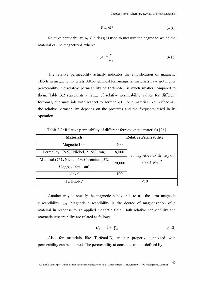
Chapter Three - Literature Review of Smart Materials
HB μ= (3-10)
Relative permeability, μr, (unitless) is used to measure the degree to which the
material can be magnetized, where:
0μμμ =r (3-11)
The relative permeability actually indicates the amplification of magnetic
effects in magnetic materials. Although most ferromagnetic materials have got higher
permeability, the relative permeability of Terfenol-D is much smaller compared to
them. Table 3.2 represents a range of relative permeability values for different
ferromagnetic materials with respect to Terfenol-D. For a material like Terfenol-D,
the relative permeability depends on the prestress and the frequency used in its
operation.
Table 3.2: Relative permeability of different ferromagnetic materials [96].
Materials Relative Permeability
Magnetic Iron 200
Permalloy (78.5% Nickel, 21.5% Iron) 8,000
Mumetal (75% Nickel, 2% Chromium, 5%
Copper, 18% Iron) 20,000
at magnetic flux density of
0.002 W/m2
Nickel 100
Terfenol-D <10
Another way to specify the magnetic behavior is to use the term magnetic
susceptibility; χm. Magnetic susceptibility is the degree of magnetization of a
material in response to an applied magnetic field. Both relative permeability and
magnetic susceptibility are related as follows:
mr χμ += 1 (3-12)
Also for materials like Terfenol-D, another property connected with
permeability can be defined. The permeability at constant strain is defined by:
_______________________________________________________________________________________________________________ A Finite Element Approach for the Implementation of Magnetostrictive Material Terfenol-D in Automotive CNG Fuel Injection Actuation
40

Chapter Three - Literature Review of Smart Materials
( )2333333 1 kTS −⋅= μμ (3-13)
This property applies to smart materials like Terfenol-D and is useful when it
is in the “blocked” state. In the blocked state the material is prevented from
increasing its strain by external forces and so no further rotations of magnetic
domains are possible [89].
3.5.6 Hysteresis loop of Terfenol-D
A hysteresis loop contains information on magnetic properties of a material
and can be represented by the relationship between magnetic flux density (B) and
magnetic field intensity (H) and is normally called the B-H curve [94]. A material
with a wide hysteresis loop has low permeability and high remanence, coercivity,
reluctance and residual magnetism. On the contrary, a material with a narrower loop
has the opposite characteristics. For a smart material sensor and actuator, the aim is
to develop materials with the smallest hysteresis. On the other hand, a material to be
used for magnetic memory with a high capacity, a large hysteresis is required, which
is also the case in most permanent magnet applications figure 3.11 represents a
sample hysteresis loop of a ferromagnetic material.
Material magnetized to saturation by alignment of domains Magnetic
flux density (B) When driving magnetic field drops to zero, the ferromagnetic material retains a considerable degree of magnetization.
The material follows a non-linear magnetization curve when magnetized from a zero field value.
Magnetic feld intensity (H)
The driving magnetic field must be reversed and increased to a large value to drive the magnetization to zero again.
The hysteresis loop shows the nature of magnetization of a ferromagnetic material. Once the material has been driven to saturation, the magnetizing field can then be dropped to zero and the material will retain most of its magnetization.
Towards saturation in the opposite direction.
Figure 3.11: Hysteretic magnetization curve for ferromagnetic material [97].
_______________________________________________________________________________________________________________ A Finite Element Approach for the Implementation of Magnetostrictive Material Terfenol-D in Automotive CNG Fuel Injection Actuation
41

Chapter Three - Literature Review of Smart Materials
Figure 3.12 represents the magnetic behavior of Terfenol-D, which shows the
material response to an applied magnetic field (H) against magnetic flux density (B).
It was found that for higher amounts of pre-stress, the relative permeability was
reduced. This could be due to the fact that for positive magnetostrictive materials
when the prestress is high, the domain movement requires more mechanical energy
and therefore the material was unable to respond to the magnetic field as it could
when the pre-stress was lower [71].
+100 -100
+1
-1
H [kA/m]
B [T] 0.725 KSI
0 KSI
Figure 3.12: General B-H curve of Terfenol-D.
Furthermore, a typical hysteresis loop for a Terfenol-D sample, showing
magnetostrictive strain in response to the magnetic field is shown in figure 3.13.
Figure 3.13: Full loop of magnetization [98].
_______________________________________________________________________________________________________________ A Finite Element Approach for the Implementation of Magnetostrictive Material Terfenol-D in Automotive CNG Fuel Injection Actuation
42
Chapter Three - Literature Review of Smart Materials
In addition to the ferromagnetic effect or magnetic flux amplification, this
change in strain is yet another response to the applied magnetic field. Although these
two effects are related, their correlation is complicated. However, several hysteresis
models have already been introduced regarding this purpose [99,100].
3.5.7 Blocked force of Terfenol-D
During magnetostrictive strain, the maximal achievable force is called the
blocked force. A simple force-displacement relationship is valid for elastic behavior:
LSF mT Δ⋅= (3-14)
In this equation Sm is the stiffness of the active element and is defined by:
LAES
H
m⋅
= (3-15)
In this equation, EH is the Young's modulus (at constant magnetic field), A is
the cross sectional area and L is the length of the Terfenol-D element. Combining
Eq.(3-12) and (3-13), substituting stiffness and magnetostrictive strain (λ =∆L/L)
leads to equation of definition for a blocked force:
HHHB EAF maxλ⋅⋅= (3-16)
There is an axial force which refers to the maximum amount of
magnetostrictive strain that can be applied to a sample of Terfenol-D. This occurs at
very high magnetic field strengths (at λmax). According to this relationship the
blocked force is proportional to the Young's modulus and the maximal strain at an
applied magnetic field. [71,90].
_______________________________________________________________________________________________________________ A Finite Element Approach for the Implementation of Magnetostrictive Material Terfenol-D in Automotive CNG Fuel Injection Actuation
43

Chapter Three - Literature Review of Smart Materials
3.6 Measurements of magnetostriction
Broadly, magnetostriction measurement techniques can be classified as either
Direct or Indirect, depending on whether the strain is measured directly or the
magnetostriction is derived from a measurement of some other property dependent
upon strain. While direct methods enable the magnetostrictive strain to be measured
as a function of the applied field, indirect methods are suitable only for measuring
the saturation magnetostriction λsat [66]. Some of the most common direct
measurement techniques include the Strain Gauge method, Dilatometry method and
Optical Interferometry. In Dilatometry methods, the tunnelling tip dilatometer and
Capacitance dilatometrys are mentionable. In addition, in case of indirect
measurements, ferromagnetic resonance (FMR), small-angle-magnetization rotation
(SAMR) and strain modulated ferromagnetic resonance (SMFMR) are some of the
techniques to measure magnetostriction [66].
3.7 Production of smart materials
The raw materials of Terfenol-D are highly reactive and contain impurities.
Thus, there is no straightforward way to produce it. However, at least four different
methods have been developed for these purposes which are basically utilized on a
near-production basis [71,101,102]. The methods are Free Stand Zone Melting
(FSZM), Modified Bridgmann (MB), Sintered Powder Compact and Polymer Matrix
Composites of Terfenol-D Powder Techniques [71,102]. Among these methods, the
most common are MB and FSZM. In the FSZM-method, material in the melting zone
is held in suspension by surface stress which is also known as Directional
Solidification Method. In the MB-method, the material is melted completely and
crystals are grown starting with a seed crystal [71,101]. Both methods are used to
produce Terfenol-D rods with high magnetostriction and high energy density. On the
other hand, the sintered and composite processes are used for the production of
Terfenol-D rods for high frequency, such as higher than 1 kHz. Sinter technology
methods are also suitable for forming complex geometries. In addition, new and
optimized processing methods, like directional solidification or powder metallurgy
_______________________________________________________________________________________________________________ A Finite Element Approach for the Implementation of Magnetostrictive Material Terfenol-D in Automotive CNG Fuel Injection Actuation
44

Chapter Three - Literature Review of Smart Materials
methods possess good potential for high volume and cost-effective production
[71,102].
In case of piezoelectric actuators, piezoceramic properties such as stiffness,
capacitance, displacement, temperature stability, leakage current and lifetime are
optimally combined. Recently, actuator design and electrode structure were enhanced
by the latest advances in piezoelectric multilayer technology focusing on actuator
design with buried electrodes (cofired encapsulation) [103,104]. In addition, viscous
plastic processing (VPP) is another manufacturing method to produce lead zirconate
titanate (PZT) fibres. PZT fibres produced by this method (VPP PZT) display high
piezoelectric coefficients compared with other available PZT fibres [105].
3.8 Piezoelectric non-linearity
At low to moderate drive levels, the piezoelectric effects were relatively linear
where linear models and control laws proved to be successful. But when operated
under high power conditions, such as fast control of fuel injector, some non-linear
behaviors and exhibition of significant hysteresis of piezoelectric materials were
evident, which ought to be quantified before the materials could be employed to their
full capacity. In dynamics applications, the materials also exhibited AC losses and
resonance effects due to inherent magneto-mechanical coupling within the material
[77]. Currently, limited understanding of the non-linear behavior of materials
produced under these conditions is hindering commercialization [106].
To harness more of the piezoelectric material’s intrinsic properties,
The UK's National Measurement Laboratory [106] would investigate on methods
that could more accurately assess material performance in evermore demanding
operating conditions. This project would specifically focus on the evaluation and
prediction of heat generation and energy conversion efficiency, with the aim of
enabling more cost effective materials selection. It was imagined that the project will
provide a basis for a consistent approach to actuator selection and thus facilitate
faster product development, cost effective testing for quality inspection and faster
assessment of both new materials and product designs. It would also, in collaboration
_______________________________________________________________________________________________________________ A Finite Element Approach for the Implementation of Magnetostrictive Material Terfenol-D in Automotive CNG Fuel Injection Actuation
45

Chapter Three - Literature Review of Smart Materials
with industry, conduct a comparison of the energy efficiency of electrical to
mechanical conversion of piezoelectric, magnetostrictive and solenoid systems.
Again it would also investigate various new energy recovery techniques proposed for
piezoelectric actuators by building and testing relevant driving circuits. They
proposed that the inherent non-linearity and loss observed at high power and high
frequency would be explored using three methods, a) constant current in drive; b)
constant voltage resonant drive and c) transient/burst mode drive. These methods
would then be compared on a range of materials which would enable the industries to
select the method most suited to their requirements, materials and applications.
3.9 Real-time control of magnetostrictive actuators
It was apparent that the control of the magnetostrictive actuators was
significant in case of fuel injection at different load conditions. The design of the
control system required accurate modeling of either the static magneto-elastic
constitutive relationship or rate-dependent behavior. Also when dynamic effects were
not negligible, compensation of rate independent or hysteresis phenomena played a
key role when real-time control tasks were of concern. Particularly, in the case of fuel
injection, these types of control applications were of enormous significance due to
the necessity of precise control of fuel valve. Thus finding out new and improved
models for an advanced real-time control of these actuators were essential.
D. Davino and others [107] implied that giant magnetostrictive materials
(GMM) could be employed as active materials in smart actuators either for quasi-
static and dynamic applications requiring suitable modeling for control tasks. In
particular, these materials could show either dynamic or rate-dependent memory
effects mixed together. They also argued that the modeling of rate independent
memory effects could be quite simple and eventually several models have been
proposed and applied in this regard. Among them, the classical Preisach model was
universally the most known [108], which allowed describing rate-independent
memory phenomena (hysteresis) quite satisfactorily with acceptable computational
cost. On the other hand, models taking dynamic effects into account have been
proposed in later years [109], which were based on the superposition of dynamic
_______________________________________________________________________________________________________________ A Finite Element Approach for the Implementation of Magnetostrictive Material Terfenol-D in Automotive CNG Fuel Injection Actuation
46

Chapter Three - Literature Review of Smart Materials
versions of hysteresis operators (ideal relay and play operators). Unfortunately, they
suffered of a quite heavy computational cost. To overcome these problems in cases
where computational efficiency was obligatory, simple approaches obtained by
Preisach-like operators and linear dynamic models were also investigated [110].
Furthermore, when feedback control applications were concerned, irrelevant to the
model of the actuator employed, the availability of efficient procedures for hysteresis
and non-linearity compensation was obligatory [111].
Cavallo and others [111] implied that the compensation of hysteretic operators
was not only a tricky mathematical task, but could facilitate the design of feedback
control systems employing nonlinear actuators with hysteresis. The problem was
originally tackled by Krasnoselskii [112]. Furthermore, according to Krejci et al.
[113], a class of simplified Preisach hysteresis operators having an exact inverse
were defined. Recently, these results have been slightly generalized by Visone and
others [114]. The employment of inverse of simplified Preisach hysteresis operators
was effective in several applications like magnetic field computation in magnetic
materials [115]. Conversely, in order to guarantee better accuracy, a general version
of Preisach model was necessary for control purposes [107].
According to an experiment performed by D. Davino and others [107], where
the performance of the feedback system comprised a standard regulator combined
with two different compensation algorithms (pseudo-compensator operator and exact
inverse numerical operator), showed good performance in terms of computational
efficiency. According to them, both of the compensated algorithms outperformed the
compensated case and the proposed fast inverse algorithm allowed both to reduce the
tracking error while speeding up the computation improving real-time performances
of the feedback control system.
3.10 Recent developments
According to an invention by P.R. Czimmek [75], his preferred embodiments
overcame many of the limitations of conventional electromechanical fuel injectors
and piezoelectric-actuated fuel injectors by providing a magnetostrictive material that
_______________________________________________________________________________________________________________ A Finite Element Approach for the Implementation of Magnetostrictive Material Terfenol-D in Automotive CNG Fuel Injection Actuation
47

Chapter Three - Literature Review of Smart Materials
enabled precise control of fuel through the metering valve by converting magnetic
energy into mechanical energy using materials with giant magnetostrictive
properties. Magnetostrictive actuation is especially advantageous in high pressure
direct fuel injection applications because the high force of the magnetostrictive
actuator easily overcomes the fuel pressure force. Czimmek mainly suggested that
the coil current should be maintained within a reasonable range that would avoid
saturating the magnetostrictive material or dissipating excessive power in the coil.
A collaborative project between ORNL, Detroit Diesel Corporation and Wayne
State University [116] developed a piezoelectric control valve actuator which
comprises of a piezo stack, piston, plunger and a control valve as main components.
Their first phase focused on characterization of the piezo stacks and fuel injection
application validation via static and dynamic tests where piezo stack gave shorter
response time compared to solenoid actuated systems. Electric current and preload
requirements were optimized at specified voltage levels. The required control valve
motion was achieved through design and development of a hydraulic amplification
system. For fuel systems, they used valves with shorter strokes which did not require
motion amplification. At the end, they reduced the cost of actuator by allowing the
use of lower-cost silver interlayer electrodes by fabricating the PZT stacks using
ORNL low-sintering-temperature PZT. They were also able to increase the strength
of ORNL composition by adding a ceramic agent to it, which eventually enhanced
the reliability and life time of the actuator.
Regarding the actuation of a piezo driven control valve, according to a study
by Detroit Diesel Corporation [117], the actuation delay was an order of magnitude
shorter and the rise time was three times faster compared to a solenoid driven one.
They also summarized that piezo actuators have a different dynamic behavior
implying the necessity of different control strategies.
_______________________________________________________________________________________________________________ A Finite Element Approach for the Implementation of Magnetostrictive Material Terfenol-D in Automotive CNG Fuel Injection Actuation
48

Chapter Three - Literature Review of Smart Materials
3.11 Summary of chapter three
Present solenoid fuel injection expertise might not be sufficient enough to meet
the future emission reduction legislations due to its limitations regarding actuator
response time. In this context, magnetostrictive materials offer enormous prospects in
terms of their exquisite rapid response time through which precise amount of fuel can
be injected according to the power requirement, which being the significant
prerequisite for emission reduction. Furthermore, features like accuracy, power
density and dynamic performance of this smart technology are excellent
characteristics for the implementation of this technology into high volume
automotive applications. In addition, stable characteristics over a wide temperature
range and high magnetostrictive co-efficient are evident in enhanced materials like
Terfenol-D, which are excellent parameters for actuation against high back pressure.
However, further research for developing new and improved actuator structures is
mandatory to enhance the capability of magnetostrictive technology regarding
functional superiority and cost reduction. A concise and inclusive overview of the
highlighted research process of this chapter is shown in figure 3.14.
_______________________________________________________________________________________________________________ A Finite Element Approach for the Implementation of Magnetostrictive Material Terfenol-D in Automotive CNG Fuel Injection Actuation
49
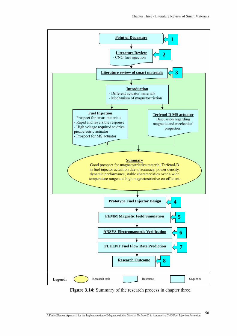
Chapter Three - Literature Review of Smart Materials
Point of Departure
Figure 3.14: Summary of the research process in chapter three.
1
Literature Review 2 - CNG fuel injection
FLUENT Fuel Flow Rate Prediction
Research Outcome
Prototype Fuel Injector Design
Legend: Research task Resource Sequence
4
7
8
ANSYS Electromagnetic Verification
FEMM Magnetic Field Simulation
3 Literature review of smart materials
6
5
Introduction - Different actuator materials - Mechanism of magnetostriction
Fuel Injection Terfenol-D MS actuator- Prospect for smart materials
Discussion regarding
magnetic and mechanical properties.
- Rapid and reversible response - High voltage required to drive piezoelectric actuator - Prospect for MS actuator
Summary Good prospect for magnetostrictive material Terfenol-D in fuel injector actuation due to accuracy, power density, dynamic performance, stable characteristics over a wide
temperature range and high magnetostrictive co-efficient.
_______________________________________________________________________________________________________________ A Finite Element Approach for the Implementation of Magnetostrictive Material Terfenol-D in Automotive CNG Fuel Injection Actuation
50

CHAPTER FOUR
FUEL INJECTOR DESIGN
CONCEPT AND
ACTUATING PARAMETER
DETERMINATION
Chapter Four - Fuel Injector Design Concept and Actuating Parameter Determination
4.1 Introduction
This chapter presents a prototype CNG fuel injector design concept utilizing
magnetostrictive material Terfenol-D as the fuel injector actuator. A detailed
description of the mechanism of the fuel injector assembly will also be presented.
Furthermore, the parameters required to actuate the injector, such as the required
magnetic field strength to cause the necessary strain in the magnetostrictive material
will also be determined.
4.2 Prototype CNG fuel injector
A prototype fuel injector assembly was designed using Pro/Engineer Wildfire
3.0, which is a 3D CAD parametric feature solid modeling software created by
Parametric Technology Corporation (PTC), as shown in figure 4.1. A Terfenol-D
shaft (30mm x 50mm) was used as the core actuator material. The injector housing
was composed of 1020 Steel, which is a low carbon steel having soft magnetic
material properties. Regarding the coil material, in order to simulate the variation of
the magnetic flux density and magnetizing force to achieve a desired strain output or
injector lift, four different types of American Wire Gauge (AWG) were utilized,
which is a standardized wire gauge system especially for nonferrous and electrically
conducting wire. These are namely; 22 AWG, 24 AWG, 28 AWG and 30 AWG copper
wires. The plunger was composed of 316 Stainless Steel having non-magnetic
properties. While a Coil Spring acted as the closing spring having the task of
bringing the needle valve to a closed position, a Belleville Spring was used as the
prestress spring which had the task of providing axial prestress to the Terfenol-D
shaft. The fuel injector assembly and component dimensions are summarized in the
appendix B.
_______________________________________________________________________________________________________________ A Finite Element Approach for the Implementation of Magnetostrictive Material Terfenol-D in Automotive CNG Fuel Injection Actuation
51
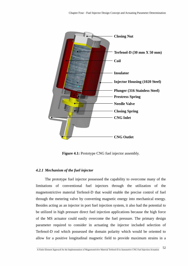
Chapter Four - Fuel Injector Design Concept and Actuating Parameter Determination
Figure 4.1: Prototype CNG fuel injector assembly.
Closing Nut
Terfenol-D (30 mm X 50 mm)
Coil
Insulator
Injector Housing (1020 Steel)
Plunger (316 Stainless Steel) Prestress Spring
Needle Valve
Closing Spring
CNG Inlet
CNG Outlet
4.2.1 Mechanism of the fuel injector
The prototype fuel injector possessed the capability to overcome many of the
limitations of conventional fuel injectors through the utilization of the
magnetostrictive material Terfenol-D that would enable the precise control of fuel
through the metering valve by converting magnetic energy into mechanical energy.
Besides acting as an injector in port fuel injection system, it also had the potential to
be utilized in high pressure direct fuel injection applications because the high force
of the MS actuator could easily overcome the fuel pressure. The primary design
parameter required to consider in actuating the injector included selection of
Terfenol-D rod which possessed the domain polarity which would be oriented to
allow for a positive longitudinal magnetic field to provide maximum strains in a
_______________________________________________________________________________________________________________ A Finite Element Approach for the Implementation of Magnetostrictive Material Terfenol-D in Automotive CNG Fuel Injection Actuation
52
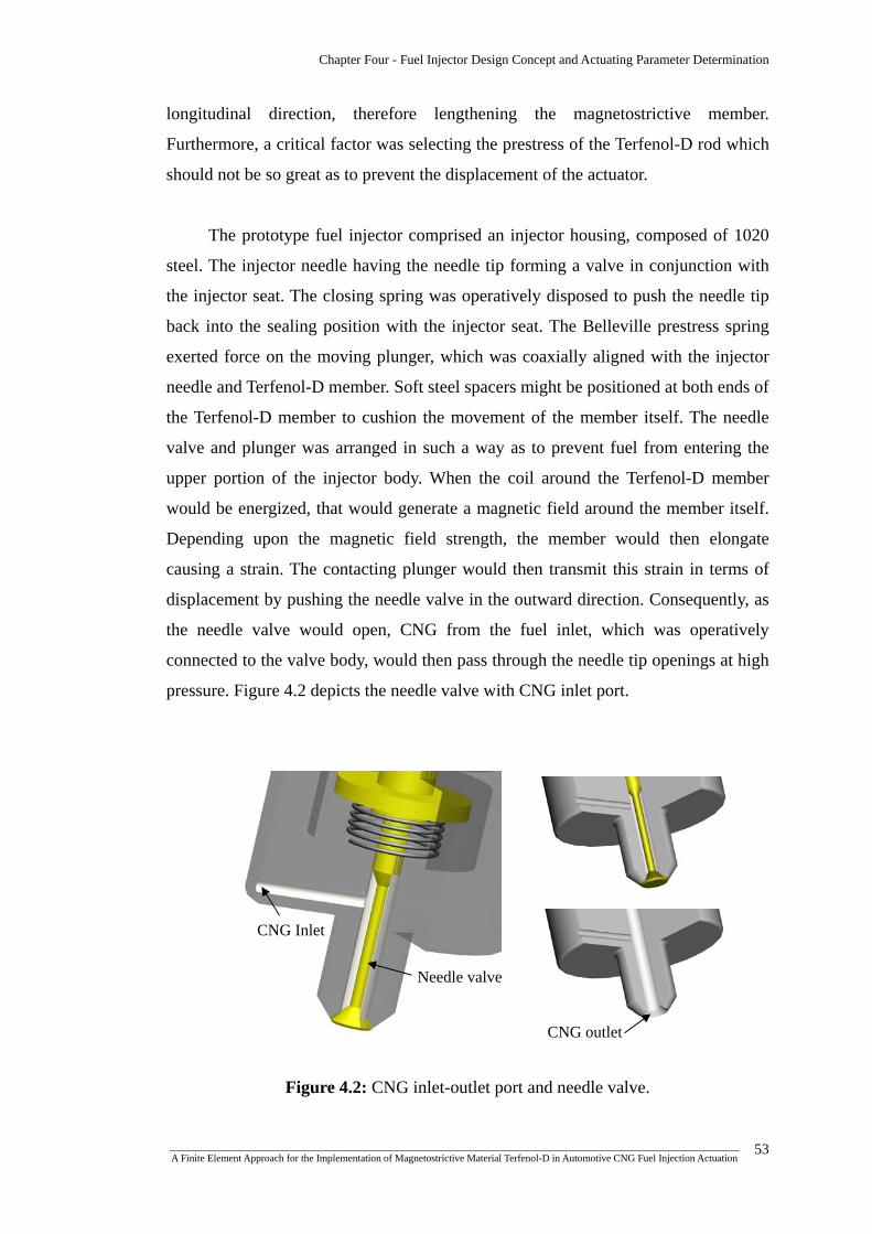
Chapter Four - Fuel Injector Design Concept and Actuating Parameter Determination
longitudinal direction, therefore lengthening the magnetostrictive member.
Furthermore, a critical factor was selecting the prestress of the Terfenol-D rod which
should not be so great as to prevent the displacement of the actuator.
The prototype fuel injector comprised an injector housing, composed of 1020
steel. The injector needle having the needle tip forming a valve in conjunction with
the injector seat. The closing spring was operatively disposed to push the needle tip
back into the sealing position with the injector seat. The Belleville prestress spring
exerted force on the moving plunger, which was coaxially aligned with the injector
needle and Terfenol-D member. Soft steel spacers might be positioned at both ends of
the Terfenol-D member to cushion the movement of the member itself. The needle
valve and plunger was arranged in such a way as to prevent fuel from entering the
upper portion of the injector body. When the coil around the Terfenol-D member
would be energized, that would generate a magnetic field around the member itself.
Depending upon the magnetic field strength, the member would then elongate
causing a strain. The contacting plunger would then transmit this strain in terms of
displacement by pushing the needle valve in the outward direction. Consequently, as
the needle valve would open, CNG from the fuel inlet, which was operatively
connected to the valve body, would then pass through the needle tip openings at high
pressure. Figure 4.2 depicts the needle valve with CNG inlet port.
Figure 4.2: CNG inlet-outlet port and needle valve.
CNG Inlet
Needle valve
CNG outlet
_______________________________________________________________________________________________________________ A Finite Element Approach for the Implementation of Magnetostrictive Material Terfenol-D in Automotive CNG Fuel Injection Actuation
53

Chapter Four - Fuel Injector Design Concept and Actuating Parameter Determination
4.3 Fuel injector component material properties
The material properties of the injector housing and plunger were significant as
these materials were utilized in the electromagnetic simulation of the fuel injector. In
case of the injector housing and plunger, 1020 Steel and 316 Stainless Steel were
utilized respectively. The detailed discussion regarding the material properties of
Terfenol-D have already been discussed in section 3.5.
4.3.1 1020 Steel
1020, a commonly used plain carbon steel having soft magnetic properties,
possess a nominal carbon content of 0.20% with approximately 0.50% manganese.
Furthermore, it possess a good combination of strength and ductility and might be
hardened or carburized. It also possesses good machinability and formability with
readily weldable capability by all standard welding methods [118]. Moreover, table
4.1 shows the typical material properties and figure 4.3 describes the non-linear B-H
properties of 1020 steel.
Table 4.1: Typical material properties of 1020 Steel [118,119]
Chemical properties
Carbon (C) 0.17-0.23%
Iron (Fe) Balance
Manganese (Mn) 0.3-0.6%
Phosphorus (P) 0.04% max
Sulphur (S) 0.05% max
Physical properties
Density (x 1000 kg/m3) @ 25oC 7.7-8.03
Relative permeability 760
Poissons Ratio @ 25oC 0.27-0.30
Thermal Expansion (10-6/oC)
@ 20-700oC annealed treatment14.8
Elastic Modulus (GPa) @ 25oC 190-210
Tensile Strength (MPa) 394.7
Yield Strength, (MPa) 294.8
_______________________________________________________________________________________________________________ A Finite Element Approach for the Implementation of Magnetostrictive Material Terfenol-D in Automotive CNG Fuel Injection Actuation
54

Chapter Four - Fuel Injector Design Concept and Actuating Parameter Determination
Figure 4.3: Non-linear B-H data of 1020 Steel from FEMM materials Library.
4.3.2 Grade 316 Stainless Steel
In case of the fuel injector, the plunger needed to be non-responsive to the
magnetic field in order to avoid the solenoid effect in the plunger itself. Otherwise,
there might be different relative motions generated between Terfenol-D and plunger
resulting in less or improper injector lift. Besides, redundant impact resulting in wear
might be another possibility.
Grade 316 is a standard molybdenum-bearing grade in austenitic range, thus
having very low magnetic permeability showing no response to a magnet when in the
annealed condition. The change in magnetic response is actually due to atomic lattice
straining and martensite formation. Generally, if the nickel to chromium ratio in the
material composition is higher, the austenitic structure becomes more stable showing
less magnetic response. This high nickel to chromium ratio is evident in grade 316
stainless steel structure, thus imposing low magnetic response [120].
Furthermore, 316 Stainless Steel possess high corrosion resistance, more
resistant to carbide precipitation, excellent weldability by all standard fusion methods
and upgraded machining characteristics. The austenitic structure also gives these
grades excellent toughness characteristics [120]. Table 4.2 depicts the typical
material properties of the 316 Stainless Steel.
_______________________________________________________________________________________________________________ A Finite Element Approach for the Implementation of Magnetostrictive Material Terfenol-D in Automotive CNG Fuel Injection Actuation
55

Chapter Four - Fuel Injector Design Concept and Actuating Parameter Determination
Table 4.2: Typical material properties of 316 Stainless Steel [120]
Chemical properties
Carbon (C) <0.03%
Iron (Fe) Balance
Chromium (Cr) 16-18.5%
Nickel (Ni) 10-14%
Molybdenum (Mo) 2-3%
Manganese (Mn) <2%
Silicon (Si) <1%
Phosphorus (P) <0.045%
Sulphur (S) <0.03%
Physical properties
Density (kg/m3) 8000
Elastic Modulus (GPa) 193
@ 100oC 16.3 Thermal Conductivity (W/m.K)
@500oC 21.5
Specific Heat, 0-100oC (J/kg.K) 500
Electric Resistivity (nΩ.m) 740
4.4 Actuating parameter determination
Before approaching the electromagnetic simulation, the required parameters for
the desired magnetostrictive strain or injector lift had to be predetermined. For a
desired injector lift of 50 microns and for a 50 mm long Terfenol-D member, the
required magnetostrictive strain was around 1000 ppm. From figure 4.4, in order to
achieve this amount of strain, for 1 KSI preload, the applied magnetic field needed to
be around 500 Oersted (Oe), which was about 40,000 A/m of magnetizing force (H).
_______________________________________________________________________________________________________________ A Finite Element Approach for the Implementation of Magnetostrictive Material Terfenol-D in Automotive CNG Fuel Injection Actuation
56

Chapter Four - Fuel Injector Design Concept and Actuating Parameter Determination
Figure 4.4: Terfenol-D strain vs. applied field at various preloads, data from
ETREMA PRODUCTS INC.
Terfenol-D Strain vs. Applied field
500
Although the actual B-H curve of ferromagnetic materials could be represented
as figure 4.5, in this case, the B-H curve of Terfenol-D was treated approximately as
linear as the desired and operational values of the flux density and the magnetizing
force were far below the saturation point. In this region, the graph could be
represented as figure 4.6 where the Terfenol-D B-H data were provided by ETREMA
PRODUCTS INC.
Figure 4.5: Hysteretic magnetization curve for a ferromagnetic material and relevant
points: BBR, remnance; (HS, BSB ), saturation; and HC, coercitive field strength [72].
_______________________________________________________________________________________________________________ A Finite Element Approach for the Implementation of Magnetostrictive Material Terfenol-D in Automotive CNG Fuel Injection Actuation
57
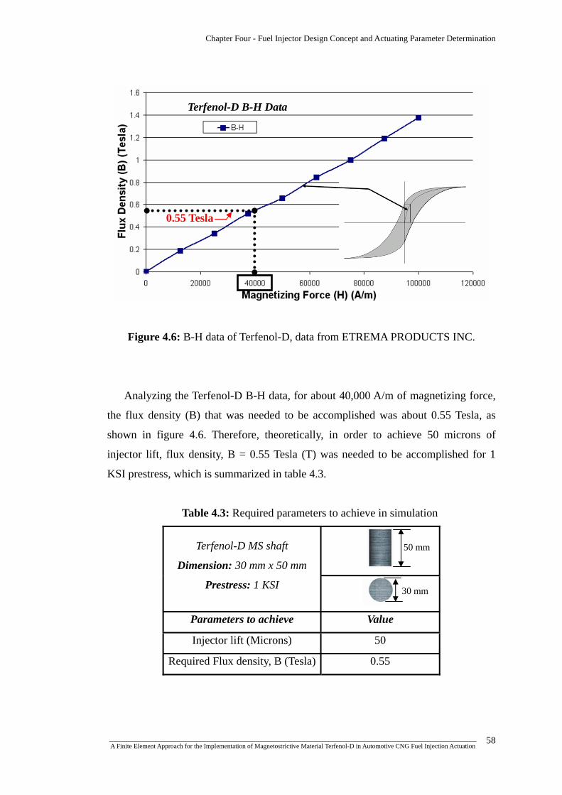
Chapter Four - Fuel Injector Design Concept and Actuating Parameter Determination
Figure 4.6: B-H data of Terfenol-D, data from ETREMA PRODUCTS INC.
Terfenol-D B-H Data
0.55 Tesla
Analyzing the Terfenol-D B-H data, for about 40,000 A/m of magnetizing force,
the flux density (B) that was needed to be accomplished was about 0.55 Tesla, as
shown in figure 4.6. Therefore, theoretically, in order to achieve 50 microns of
injector lift, flux density, B = 0.55 Tesla (T) was needed to be accomplished for 1
KSI prestress, which is summarized in table 4.3.
Table 4.3: Required parameters to achieve in simulation
Terfenol-D MS shaft
Dimension: 30 mm x 50 mm
Prestress: 1 KSI
Parameters to achieve Value
Injector lift (Microns) 50
Required Flux density, B (Tesla) 0.55
50 mm
30 mm
_______________________________________________________________________________________________________________ A Finite Element Approach for the Implementation of Magnetostrictive Material Terfenol-D in Automotive CNG Fuel Injection Actuation
58

Chapter Four - Fuel Injector Design Concept and Actuating Parameter Determination
4.5 Summary of chapter four
A prototype CNG fuel injector assembly was designed utilizing
magnetostrictive material Terfenol-D as the actuator material. Furthermore, the
associated fuel injector component material properties were highlighted. Next
upcoming chapters would emphasize on generating the identical fuel injector model
in the simulated environments with the corresponding material properties. In this
context, the parameters required to achieve the desired magnetic field strength to
cause the necessary magnetostrictive strain were predetermined in order to initiate
the electromagnetic and computational fluid dynamics simulations. A concise and
inclusive overview of the highlighted research process of this chapter is shown in
figure 4.7.
_______________________________________________________________________________________________________________ A Finite Element Approach for the Implementation of Magnetostrictive Material Terfenol-D in Automotive CNG Fuel Injection Actuation
59
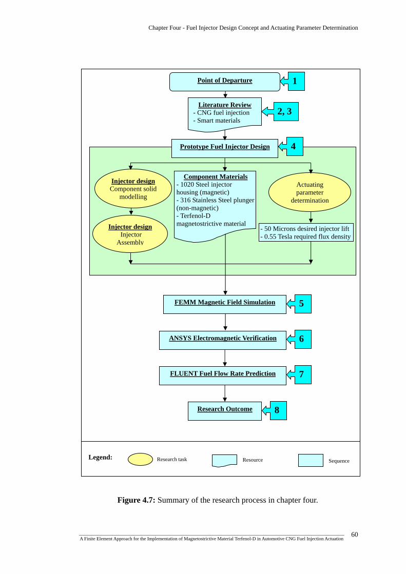
Chapter Four - Fuel Injector Design Concept and Actuating Parameter Determination
FEMM Magnetic Field Simulation
Injector design Component solid
modelling
Injector design Injector
Assembly
Actuating parameter
determination
- 50 Microns desired injector lift - 0.55 Tesla required flux density
5
Component Materials - 1020 Steel injector housing (magnetic) - 316 Stainless Steel plunger (non-magnetic) - Terfenol-D magnetostrictive material
1
2, 3
4 Prototype Fuel Injector Design
Literature Review - CNG fuel injection - Smart materials
Point of Departure
6 ANSYS Electromagnetic Verification
7 FLUENT Fuel Flow Rate Prediction
8 Research Outcome
Research task Legend: Resource Sequence
Figure 4.7: Summary of the research process in chapter four.
_______________________________________________________________________________________________________________ A Finite Element Approach for the Implementation of Magnetostrictive Material Terfenol-D in Automotive CNG Fuel Injection Actuation
60

CHAPTER FIVE
FEMM MAGNETIC FIELD
SIMULATION

Chapter Five - FEMM Magnetic Field Simulation
5.1 Introduction
Finite Element Method Magnetics (FEMM) is a finite element software
package for solving low frequency electromagnetic problems on two-dimensional
planar and axisymmetric domains developed by David Meeker of Foster-Miller, Inc
[121]. The package is composed of an interactive shell which is a Multiple
Document Interface pre-processor and a post-processor, a triangular mesh generator
and various solvers for linear or nonlinear magneto-static and time harmonic
magnetic problems, linear electrostatic problems and steady-state heat flow
problems. In this chapter, FEMM version 4.2 was utilized to perform the magnetics
simulations.
The purpose of this chapter is to present the methodology and results of the
non-linear, axisymmetric magnetics simulation to obtain the desired magnetic field
strength in order to achieve the magnetostrictive strain while minimizing the power
consumption of the coil circuitry.
5.2 Relevant Partial Differential Equations
5.2.1 Magnetostatic problems
In case of magnetostatic problems, the fields are time-invariant. For such cases,
the field intensity ( H ) and flux density ( B ) must obey:
JH =×∇ (5-1)
Where, J denotes current density.
0=⋅∇ B (5-2)
Again, the constitutive relationship between B and H for each material being:
HB
=μ (5-3)
_______________________________________________________________________________________________________________ A Finite Element Approach for the Implementation of Magnetostrictive Material Terfenol-D in Automotive CNG Fuel Injection Actuation
61

Chapter Five - FEMM Magnetic Field Simulation
However, for nonlinear material properties, the permeability μ is actually a
function of B :
)(BH
B=μ (5-4)
Now, flux density can be written in terms of vector potential, A , as:
AB ×∇= (5-5)
FEMM actually searches for a field that satisfies from Eq. (5-1) to (5-3) via
this magnetic vector potential approach. Now, as the definition of B always satisfies
Eq. (5-2), then Eq. (5-1) can be written as:
( ) JAB
=⎟⎟⎠
⎞⎜⎜⎝
⎛×∇×∇
μ1
(5-6)
Again, for a linear isotropic material and also assuming the Coulomb gauge,
0=⋅∇ A , Eq. (5-6) reduces to:
JA =∇−21
μ (5-7)
In order to solve magnetostatic problems with a non-linear B-H relationship,
FEMM utilizes Eq. (5-6) [122].
5.2.2 Time-harmonic magnetics problem
If the frequency is non-zero or the magnetic field is time varying, the program
will perform a harmonic analysis, in which all field quantities are oscillating at this
prescribed frequency. Denoting the electric field intensity as E and the current
density as J ; they obey the constitutive relationship:
EJ σ= (5-8)
_______________________________________________________________________________________________________________ A Finite Element Approach for the Implementation of Magnetostrictive Material Terfenol-D in Automotive CNG Fuel Injection Actuation
62

Chapter Five - FEMM Magnetic Field Simulation
Where, σ represents electrical conductivity.
The induced electric field follows:
tBE∂∂
−=×∇ (5-9)
Substituting the vector potential form of B into Eq.(5-9) yields,
AE &×∇−=×∇ (5-10)
Now, in case of two-dimensional problems, Eq.(5-10) can be integrated to yield:
VAE ∇−−= & (5-11)
Now, from Eq. (5-8),
VAJ ∇−−= σσ & (5-12)
Now, substituting into Eq.(5-6) yields the partial differential equation,
( ) VJAAB
src ∇−+−=⎟⎟⎠
⎞⎜⎜⎝
⎛×∇×∇ σσ
μ&1
(5-13)
Where, srcJ represents the applied current source and V∇ is an additional
voltage gradient which is constant over a conducting body in two-dimensional
problems. FEMM considers Eq. (5-13) for the case in which the field is oscillating at
one fixed frequency [122].
5.3 Model Construction and Analysis
As mentioned in the previous chapter, the FEMM magnetics simulations would
be carried out for four different AWG wire types and four different coil thicknesses.
The model to be analyzed is shown in figure 5.1.
_______________________________________________________________________________________________________________ A Finite Element Approach for the Implementation of Magnetostrictive Material Terfenol-D in Automotive CNG Fuel Injection Actuation
63
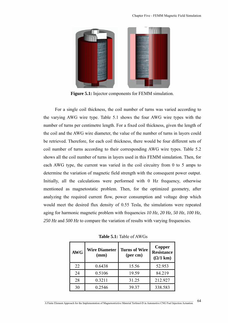
Chapter Five - FEMM Magnetic Field Simulation
Figure 5.1: Injector components for FEMM simulation.
For a single coil thickness, the coil number of turns was varied according to
the varying AWG wire type. Table 5.1 shows the four AWG wire types with the
number of turns per centimetre length. For a fixed coil thickness, given the length of
the coil and the AWG wire diameter, the value of the number of turns in layers could
be retrieved. Therefore, for each coil thickness, there would be four different sets of
coil number of turns according to their corresponding AWG wire types. Table 5.2
shows all the coil number of turns in layers used in this FEMM simulation. Then, for
each AWG type, the current was varied in the coil circuitry from 0 to 5 amps to
determine the variation of magnetic field strength with the consequent power output.
Initially, all the calculations were performed with 0 Hz frequency, otherwise
mentioned as magnetostatic problem. Then, for the optimized geometry, after
analyzing the required current flow, power consumption and voltage drop which
would meet the desired flux density of 0.55 Tesla, the simulations were repeated
aging for harmonic magnetic problem with frequencies 10 Hz, 20 Hz, 50 Hz, 100 Hz,
250 Hz and 500 Hz to compare the variation of results with varying frequencies.
Table 5.1: Table of AWGs
AWG Wire Diameter(mm)
Turns of Wire(per cm)
Copper Resistance (Ω/1 km)
22 0.6438 15.56 52.953 24 0.5106 19.59 84.219 28 0.3211 31.25 212.927 30 0.2546 39.37 338.583
_______________________________________________________________________________________________________________ A Finite Element Approach for the Implementation of Magnetostrictive Material Terfenol-D in Automotive CNG Fuel Injection Actuation
64

Chapter Five - FEMM Magnetic Field Simulation
Table 5.2: Coil number of turns in layers.
Coil Thickness, t
mm AWG
Number of
Turns Layers
22 252 3
24 423 4
28 1012 6 2
30 1700 8
22 420 5
24 635 6
28 1518 9 3
30 2551 12
22 504 6
24 846 8
28 2025 12 4
30 3402 16
22 672 8
24 1058 10
28 2700 16 5
30 4252 20
5.3.1 Problem definition and creating model geometry
FEMM contains a CAD like interface for laying out the geometry of the
problem to be solved and for defining material properties and boundary conditions.
Initially, the simulation type was set as magnetics. Then, in the problem definition
dialog box, the Problem Type was set as axisymmetric, the Length Units was set to
millimeters (mm) and the frequency was set according to the criteria, as shown in
figure 5.2. The depth specification box only got enabled when a Planer problem was
selected.
_______________________________________________________________________________________________________________ A Finite Element Approach for the Implementation of Magnetostrictive Material Terfenol-D in Automotive CNG Fuel Injection Actuation
65
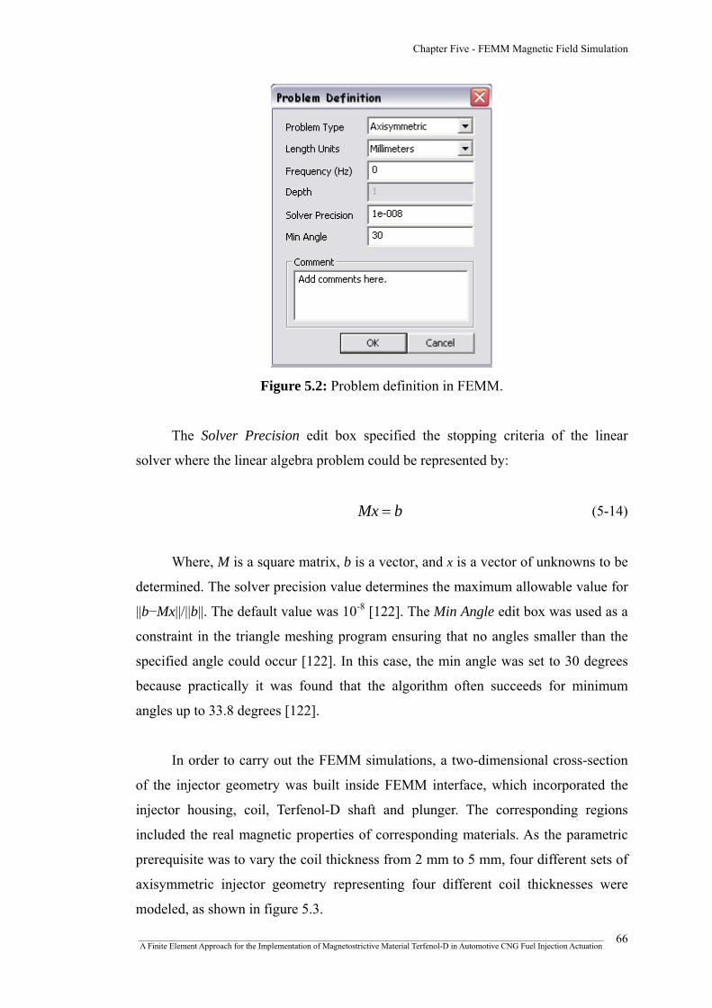
Chapter Five - FEMM Magnetic Field Simulation
Figure 5.2: Problem definition in FEMM.
The Solver Precision edit box specified the stopping criteria of the linear
solver where the linear algebra problem could be represented by:
bMx = (5-14)
Where, M is a square matrix, b is a vector, and x is a vector of unknowns to be
determined. The solver precision value determines the maximum allowable value for
||b−Mx||/||b||. The default value was 10-8 [122]. The Min Angle edit box was used as a
constraint in the triangle meshing program ensuring that no angles smaller than the
specified angle could occur [122]. In this case, the min angle was set to 30 degrees
because practically it was found that the algorithm often succeeds for minimum
angles up to 33.8 degrees [122].
In order to carry out the FEMM simulations, a two-dimensional cross-section
of the injector geometry was built inside FEMM interface, which incorporated the
injector housing, coil, Terfenol-D shaft and plunger. The corresponding regions
included the real magnetic properties of corresponding materials. As the parametric
prerequisite was to vary the coil thickness from 2 mm to 5 mm, four different sets of
axisymmetric injector geometry representing four different coil thicknesses were
modeled, as shown in figure 5.3.
_______________________________________________________________________________________________________________ A Finite Element Approach for the Implementation of Magnetostrictive Material Terfenol-D in Automotive CNG Fuel Injection Actuation
66

Chapter Five - FEMM Magnetic Field Simulation
Figure 5.3: Injector geometry in FEMM with four coil thicknesses.
5 mm 4 mm 3 mm 2 mm
5.3.2 Boundary conditions
The purpose of specifying boundary condition was to assign the properties of
line segments or arc segments that are to be boundaries of the solution domain.
Boundary conditions for magnetic and electrostatic problems come in five varieties.
These are namely, a) Dirichlet, where the value of potential A or V is explicitly
defined on the boundary; b) Neumann, where the condition of normal derivative of A
is specified which forces the flux to pass the boundary at exactly 90o angle to the
boundary; c) Robin, which is actually a sort of mix between Dirichlet and Neumann;
d) Periodic, where two boundaries are joined together and the boundary values on
corresponding points of the two boundaries are set equal to one another; and e)
Antiperiodic, which also joins two boundaries together but the boundary values are
made to be of equal magnitude but opposite sign [122].
_______________________________________________________________________________________________________________ A Finite Element Approach for the Implementation of Magnetostrictive Material Terfenol-D in Automotive CNG Fuel Injection Actuation
67
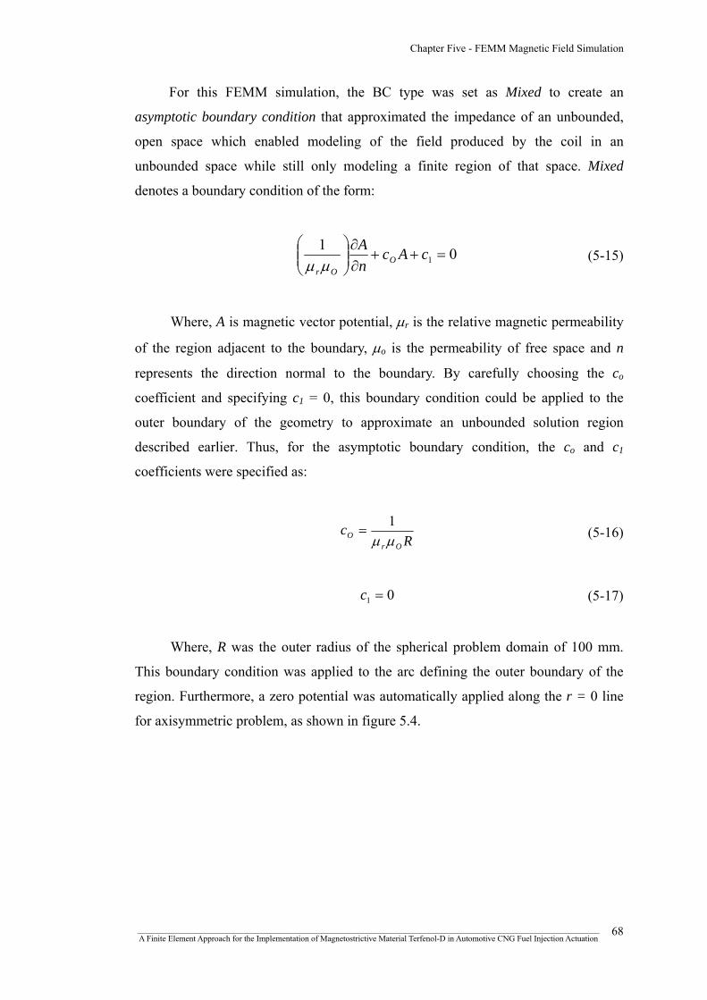
Chapter Five - FEMM Magnetic Field Simulation
For this FEMM simulation, the BC type was set as Mixed to create an
asymptotic boundary condition that approximated the impedance of an unbounded,
open space which enabled modeling of the field produced by the coil in an
unbounded space while still only modeling a finite region of that space. Mixed
denotes a boundary condition of the form:
011 =++
∂∂
⎟⎟⎠
⎞⎜⎜⎝
⎛cAc
nA
OOrμμ
(5-15)
Where, A is magnetic vector potential, μr is the relative magnetic permeability
of the region adjacent to the boundary, μo is the permeability of free space and n
represents the direction normal to the boundary. By carefully choosing the co
coefficient and specifying c1 = 0, this boundary condition could be applied to the
outer boundary of the geometry to approximate an unbounded solution region
described earlier. Thus, for the asymptotic boundary condition, the co and c1
coefficients were specified as:
Rc
OrO μμ
1= (5-16)
01 =c (5-17)
Where, R was the outer radius of the spherical problem domain of 100 mm.
This boundary condition was applied to the arc defining the outer boundary of the
region. Furthermore, a zero potential was automatically applied along the r = 0 line
for axisymmetric problem, as shown in figure 5.4.
_______________________________________________________________________________________________________________ A Finite Element Approach for the Implementation of Magnetostrictive Material Terfenol-D in Automotive CNG Fuel Injection Actuation
68

Chapter Five - FEMM Magnetic Field Simulation
Figure 5.4: Applying boundary conditions in FEMM.
+100
Asymptotic BC
0
Zero potential r = 0
-100
5.3.3 Material and circuit properties
FEMM provided a built-in material library which enabled the use of any
available material properties according to the specification for the simulation
purpose. In case of the fuel injector, the properties for 1020 steel, 316 stainless steel,
AWG copper wire and air were selected, as shown in figure 5.5. The properties of
these materials have already been depicted in chapter four.
_______________________________________________________________________________________________________________ A Finite Element Approach for the Implementation of Magnetostrictive Material Terfenol-D in Automotive CNG Fuel Injection Actuation
69

Chapter Five - FEMM Magnetic Field Simulation
Figure 5.5: Adding material properties to the model.
However, as the material properties of Terfenol-D was unavailable in the
FEMM materials library, the Terfenol-D material model was constructed from the B-
H data provided by the manufacturing company ETREMA Products, Inc., as shown
in figure 5.6. The associated properties were then attached with the block labels into
the FEMM interface which included the real magnetic properties of the
corresponding materials.
Figure 5.6: Constructing Terfenol-D material model in FEMM.
_______________________________________________________________________________________________________________ A Finite Element Approach for the Implementation of Magnetostrictive Material Terfenol-D in Automotive CNG Fuel Injection Actuation
70
Chapter Five - FEMM Magnetic Field Simulation
In order to construct the circuit property, in the circuit property dialog box, a
series circuit with circuit current (amps) was defined. For this simulation, the circuit
current was varied from 0 to 5 amps. The circuit property was then assigned to the
coil region in the injector model specifying the coil number of turns. A negative
value of the coil number of turns would indicate that the turns are wrapped in a
counter-clockwise direction.
5.3.4 Meshed geometry
The idea of finite element analysis was to discretize the problem into a large
number of regions, each with a simple geometry. Specifically, FEMM discretizes the
problem domain using triangular elements. Over each element, the solution is
approximated by a linear interpolation of the values of potential at the three vertices
of the triangle [122]. After assigning all the material properties and applying the
boundary conditions, the two-dimensional model was eventually meshed with a
coarse triangular mesh at the outside region and a finer triangular mesh at the
significant regions such as Terfenol-D core, injector housing and plunger to get more
accurate results, as shown in figure 5.7.
Figure 5.7: Meshed geometry in FEMM.
Created mesh with 19256 nodes
_______________________________________________________________________________________________________________ A Finite Element Approach for the Implementation of Magnetostrictive Material Terfenol-D in Automotive CNG Fuel Injection Actuation
71

Chapter Five - FEMM Magnetic Field Simulation
5.4 FEMM analysis results
5.4.1 Magnetostatic series circuitry
The purpose of the magnetic simulation was to get the desired flux density to
achieve the required injector lift while minimizing the power consumption of the coil
circuitry. It was found that, as the AWG number got higher, so did the power
consumption of the corresponding coil, which was identical for all four coil
thicknesses, as shown in figure 5.8.
(a) (b)
(c) (d)
Figure 5.8: Power vs. current for coil thickness; (a) t = 2mm;
(b) t = 3mm; (c) t = 4mm and (d) t = 5mm.
_______________________________________________________________________________________________________________ A Finite Element Approach for the Implementation of Magnetostrictive Material Terfenol-D in Automotive CNG Fuel Injection Actuation
72

Chapter Five - FEMM Magnetic Field Simulation
It was apparent that for any given coil thickness, the number of turns of higher
AWG wires would also increase. However, as the magnetic field intensity was
proportional to coil number of turns for a constant current flow, to achieve a desired
flux density, the coil number of turns could not be compromised. This was critical in
case of this injector model as the required injector lift could only be obtained if only
the certain flux density or field intensity could be achieved, which would eventually
cause the necessary amount of strain for a particular prestress (see figure 4.4). Thus,
lowering the number of turns or the current flow to minimize power was not an
option. Therefore, the power consumptions of high AWG wires with higher coil
thicknesses got increasingly higher.
(a) (b)
(c) (d)
Figure 5.9: Average flux density vs. current for coil thickness; (a) t = 2mm;
(b) t = 3mm; (c) t = 4mm and (d) t = 5mm.
Again, figure 5.9 showed the variation of flux density at varying circuit current
for different AWG coil wires. The horizontal line indicated the desired flux density
_______________________________________________________________________________________________________________ A Finite Element Approach for the Implementation of Magnetostrictive Material Terfenol-D in Automotive CNG Fuel Injection Actuation
73

Chapter Five - FEMM Magnetic Field Simulation
level. It was apparently clear that, although higher AWG coil types had low current
requirement in order to reach the desired flux density, their power consumption and
voltage requirement was relatively higher.
(a) (b)
(c) (d)
Figure 5.10: Current, power and voltage variation at flux density, B = 0.55 Tesla for
coil thickness; (a) t = 2mm; (b) t = 3mm; (c) t = 4mm and (d) t = 5mm.
Subsequently, figure 5.10 shows all the variations of circuit current, power and
voltage drop for the desired flux density, (B) = 0.55 Tesla. The corresponding values
of required current flow, power consumption and voltage drop were determined by
data analysis in Microsoft Office Excel 2003 using the simulation results obtained
from FEMM. Moreover, variations of power and average flux density with current
for individual coil thicknesses are further summarized in the appendix C.
_______________________________________________________________________________________________________________ A Finite Element Approach for the Implementation of Magnetostrictive Material Terfenol-D in Automotive CNG Fuel Injection Actuation
74
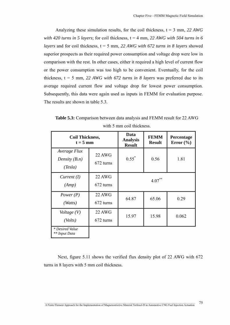
Chapter Five - FEMM Magnetic Field Simulation
Analyzing these simulation results, for the coil thickness, t = 3 mm, 22 AWG
with 420 turns in 5 layers; for coil thickness, t = 4 mm, 22 AWG with 504 turns in 6
layers and for coil thickness, t = 5 mm, 22 AWG with 672 turns in 8 layers showed
superior prospects as their required power consumption and voltage drop were low in
comparison with the rest. In other cases, either it required a high level of current flow
or the power consumption was too high to be convenient. Eventually, for the coil
thickness, t = 5 mm, 22 AWG with 672 turns in 8 layers was preferred due to its
average required current flow and voltage drop for lowest power consumption.
Subsequently, this data were again used as inputs in FEMM for evaluation purpose.
The results are shown in table 5.3.
Table 5.3: Comparison between data analysis and FEMM result for 22 AWG
with 5 mm coil thickness.
Coil Thickness, t = 5 mm
Data Analysis Result
FEMM Result
Percentage Error (%)
Average Flux
Density (B.n)
(Tesla)
22 AWG
672 turns 0.55* 0.56 1.81
Current (I)
(Amp)
22 AWG
672 turns 4.07**
Power (P)
(Watts)
22 AWG
672 turns 64.87 65.06 0.29
Voltage (V)
(Volts)
22 AWG
672 turns 15.97 15.98 0.062
* Desired Value ** Input Data
Next, figure 5.11 shows the verified flux density plot of 22 AWG with 672
turns in 8 layers with 5 mm coil thickness.
_______________________________________________________________________________________________________________ A Finite Element Approach for the Implementation of Magnetostrictive Material Terfenol-D in Automotive CNG Fuel Injection Actuation
75
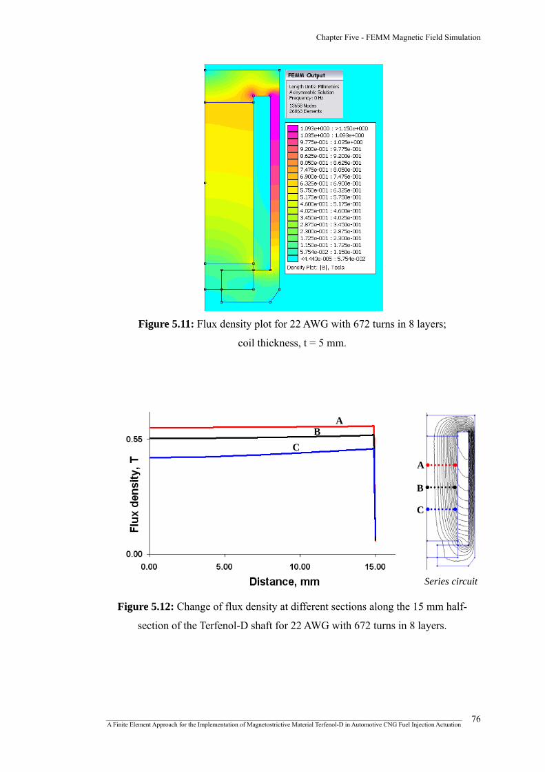
Chapter Five - FEMM Magnetic Field Simulation
Figure 5.11: Flux density plot for 22 AWG with 672 turns in 8 layers;
coil thickness, t = 5 mm.
Series circuit
Figure 5.12: Change of flux density at different sections along the 15 mm half-
section of the Terfenol-D shaft for 22 AWG with 672 turns in 8 layers.
A B
C
C
B
A
_______________________________________________________________________________________________________________ A Finite Element Approach for the Implementation of Magnetostrictive Material Terfenol-D in Automotive CNG Fuel Injection Actuation
76
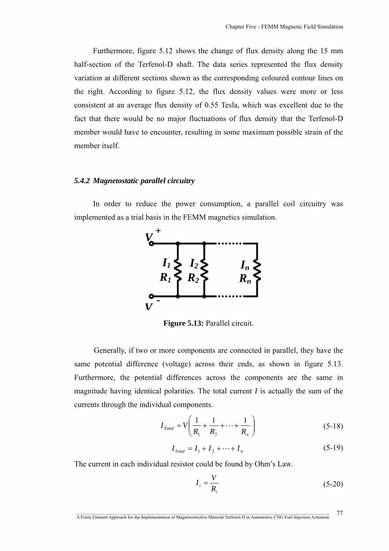
Chapter Five - FEMM Magnetic Field Simulation
Furthermore, figure 5.12 shows the change of flux density along the 15 mm
half-section of the Terfenol-D shaft. The data series represented the flux density
variation at different sections shown as the corresponding coloured contour lines on
the right. According to figure 5.12, the flux density values were more or less
consistent at an average flux density of 0.55 Tesla, which was excellent due to the
fact that there would be no major fluctuations of flux density that the Terfenol-D
member would have to encounter, resulting in some maximum possible strain of the
member itself.
5.4.2 Magnetostatic parallel circuitry
In order to reduce the power consumption, a parallel coil circuitry was
implemented as a trial basis in the FEMM magnetics simulation.
Figure 5.13: Parallel circuit.
V +
I1
R1
I2
R2
InRn
V-
Generally, if two or more components are connected in parallel, they have the
same potential difference (voltage) across their ends, as shown in figure 5.13.
Furthermore, the potential differences across the components are the same in
magnitude having identical polarities. The total current I is actually the sum of the
currents through the individual components.
⎟⎟⎠
⎞⎜⎜⎝
⎛+++=
nTotal RRR
VI 111
21
L (5-18)
nTotal IIII +++= L21 (5-19)
The current in each individual resistor could be found by Ohm’s Law.
i
i RVI = (5-20)
_______________________________________________________________________________________________________________ A Finite Element Approach for the Implementation of Magnetostrictive Material Terfenol-D in Automotive CNG Fuel Injection Actuation
77
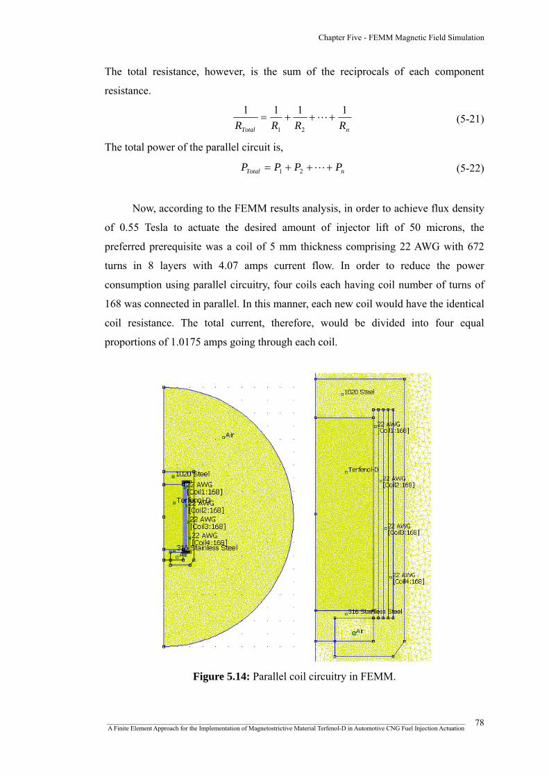
Chapter Five - FEMM Magnetic Field Simulation
The total resistance, however, is the sum of the reciprocals of each component
resistance.
nTotal RRRR
1111
21
+++= L (5-21)
The total power of the parallel circuit is,
nTotal PPPP +++= L21 (5-22)
Now, according to the FEMM results analysis, in order to achieve flux density
of 0.55 Tesla to actuate the desired amount of injector lift of 50 microns, the
preferred prerequisite was a coil of 5 mm thickness comprising 22 AWG with 672
turns in 8 layers with 4.07 amps current flow. In order to reduce the power
consumption using parallel circuitry, four coils each having coil number of turns of
168 was connected in parallel. In this manner, each new coil would have the identical
coil resistance. The total current, therefore, would be divided into four equal
proportions of 1.0175 amps going through each coil.
Figure 5.14: Parallel coil circuitry in FEMM.
_______________________________________________________________________________________________________________ A Finite Element Approach for the Implementation of Magnetostrictive Material Terfenol-D in Automotive CNG Fuel Injection Actuation
78

Chapter Five - FEMM Magnetic Field Simulation
Although, a current of 1.0175 amps through each coil or total current of 4.07
was thought to provide the same magnetic field strength, the parallel circuitry was
unable to create the desired amount of flux density with that magnitude of current
flow, as shown in figure 5.15. The reason behind this phenomenon might be, as the
individual parallel coil number of turns was reduced, it resulted in generating less
magnetic field strength for a given current flow and coil length.
B
Parallel
A
A
B
Series
Figure 5.15: Flux density variation for parallel and series coil circuitry.
Eventually it was found that, an individual current flow of 4.07 amps in each
parallel coil was essential to create the desired flux density of 0.55 Tesla, as shown in
figure 5.16. In that case, however, although the total current flow became 16.28
amps, the total power level remained 65.02 Watts. Thus, the concluding remark
would be, although it required 16.28 amps total current to derive the magnetic flux
density of 0.55 Tesla necessary to cause the magnetostrictive strain, both total power
and voltage drop were low considering the total current of the parallel circuit.
However, the total power of the parallel circuit was unchanged compared to the
series circuit having the current flow of 4.07 amps. The parallel circuit properties for
22 AWG with 672 turns in 8 layers is depicted in figure 5.17. _______________________________________________________________________________________________________________ A Finite Element Approach for the Implementation of Magnetostrictive Material Terfenol-D in Automotive CNG Fuel Injection Actuation
79

Chapter Five - FEMM Magnetic Field Simulation
A
B C
A
B
C
Parallel circuit
Figure 5.16: Change of flux density at different sections along the 15 mm half-
section of the Terfenol-D shaft for 22 AWG with 672 turns in 8 layers (t = 5 mm).
Figure 5.17: The parallel circuit properties for
22 AWG with 672 turns in 8 layers (t = 5 mm).
_______________________________________________________________________________________________________________ A Finite Element Approach for the Implementation of Magnetostrictive Material Terfenol-D in Automotive CNG Fuel Injection Actuation
80

Chapter Five - FEMM Magnetic Field Simulation
Table 5.4: Summary of the results between series and parallel circuit properties
Parallel Circuit At B = 0.55 T Series
Circuit Remarks Coil
1
Coil
2
Coil
3
Coil
4
22 AWG with 672 turns
in 8 layers; t = 5 mm
4.07 4.07 4.07 4.07 Total Current
(amps)
Higher parallel
circuit current 4.07
16.28 (=Σ)
3.56 3.84 4.13 4.43 Voltage Drop
(Volts)
Lower parallel
circuit voltage 15.97
4 (=avg)
14.47 15.66 16.84 18.04Power (watts) 64.87 Identical power
65.01 (=Σ)
Furthermore, table 5.4 describes the summary of the results between series and
parallel circuit properties to achieve the desired flux density of 0.55 Tesla for 22
AWG with 672 turns in 8 layers.
5.4.3 Time-harmonic series circuitry
In order to acquire further understanding regarding the variation of magnetic
field strength with varying frequencies, the FEMM magnetic simulations were
repeated again as harmonic magnetic problems with frequencies 10 Hz, 20 Hz, 50
Hz, 100 Hz, 250 Hz and 500 Hz. In this time-harmonic scenario, a series coil
circuitry was used which had a coil thickness of 5 mm and was composed of 22
AWG with 672 turns in 8 layers. According to the previous findings, a current flow
of 4.07 amps was applied as input circuit parameter to achieve the desired flux
density of 0.55 Tesla.
According to figure 5.18, the flux density distribution along the 15 mm half-
section of the Terfenol-D shaft was identical to that of magnetostatic series circuitry
with the same amount of current flow. However, as the frequency was increased from
0 Hz to 10 Hz, an abrupt increase in the flux density was observed, as shown in
figure 5.18 (d). Subsequently, as the frequency was increased further, the average
value of flux density tended to decrease again, as shown in figure 5.18 (b)-(c).
_______________________________________________________________________________________________________________ A Finite Element Approach for the Implementation of Magnetostrictive Material Terfenol-D in Automotive CNG Fuel Injection Actuation
81

Chapter Five - FEMM Magnetic Field Simulation
Although this phenomenon had occurred over a fraction of flux density values,
nevertheless, it was an evident feature.
(a) (b)
(d) (c)
Figure 5.18: Variation of flux density for 22 AWG with 672 turns in 8 layers with
4.07 amps input current; (a) flux density vs. distance at different frequencies; (b)
zoom in view of flux density vs. distance showing for 100 Hz, 250 Hz and 500 Hz;
(c) zoom in view of flux density vs. distance showing for 10 Hz, 20 Hz, 50 Hz and
100 Hz; (d) Flux density vs. frequency at the points (0,0), (5,0) and (10,0).
Furthermore, figure 5.19 shows the flux density vector plot and all the time-
harmonic series circuit properties output.
_______________________________________________________________________________________________________________ A Finite Element Approach for the Implementation of Magnetostrictive Material Terfenol-D in Automotive CNG Fuel Injection Actuation
82
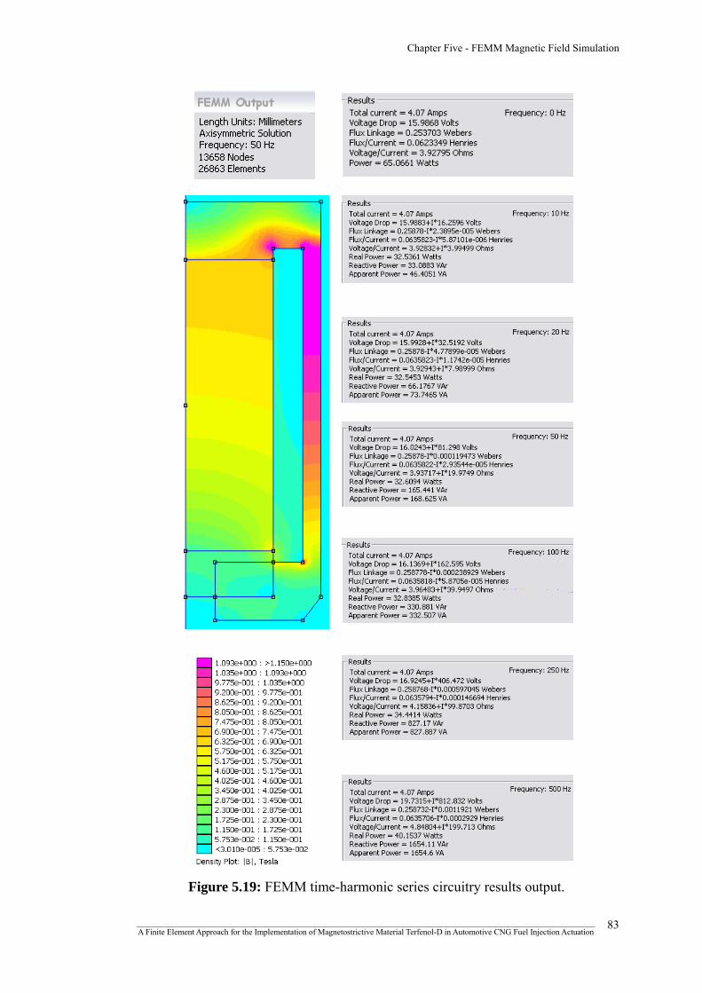
Chapter Five - FEMM Magnetic Field Simulation
Figure 5.19: FEMM time-harmonic series circuitry results output.
_______________________________________________________________________________________________________________ A Finite Element Approach for the Implementation of Magnetostrictive Material Terfenol-D in Automotive CNG Fuel Injection Actuation
83

Chapter Five - FEMM Magnetic Field Simulation
5.5 Summary of chapter five
According to the FEMM magnetic simulation results, for a coil thickness of 5
mm with 22 AWG wire having 672 turns in 8 layers, showed good prospect in
actuating the desired amount of injector lift of 50 microns as the required magnetic
field strength was achieved to cause the necessary amount of strain following the
prestress of 1 KSI in the Terfenol-D strain chart. Furthermore, in case of
magnetostatic parallel coil, it was observed that higher parallel circuit current and
lower parallel circuit voltage were required to achieve the desired flux density of
0.55 Tesla, while the coil power remained identical in both cases. Moreover, in case
of time harmonic series circuit, by implementing the frequency factor, apparently the
flux density seemed to increase suddenly. The reason behind the phenomenon of the
slight increase in flux density might be due to the fact that, as the frequency was
increased slightly, the rate of change electric field was increased also. As the strength
of the magnetic field is proportional to the time rate of the change of the electric
field, this would have resulted in an increase of magnetic field strength, resulting in
an increase in flux density. A concise and inclusive overview of the highlighted
research process of this chapter is shown in figure 5.20.
_______________________________________________________________________________________________________________ A Finite Element Approach for the Implementation of Magnetostrictive Material Terfenol-D in Automotive CNG Fuel Injection Actuation
84
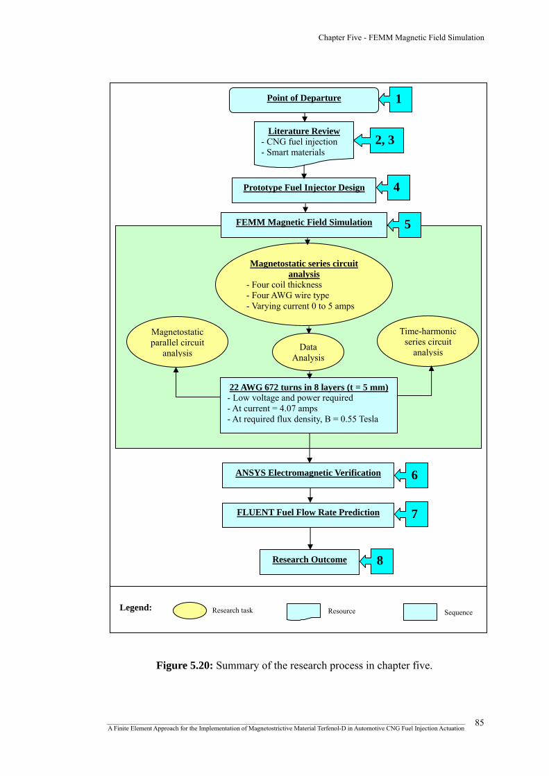
Chapter Five - FEMM Magnetic Field Simulation
1 Point of Departure
Literature Review
Figure 5.20: Summary of the research process in chapter five.
2, 3 - CNG fuel injection
- Smart materials
4 Prototype Fuel Injector Design
5 FEMM Magnetic Field Simulation
Magnetostatic series circuit analysis
- Four coil thickness - Four AWG wire type - Varying current 0 to 5 amps
Time-harmonic series circuit
analysis
Magnetostatic parallel circuit
analysis Data
Analysis
ANSYS Electromagnetic Verification
Research Outcome
Research task Legend: Resource Sequence
FLUENT Fuel Flow Rate Prediction
6
7
8
22 AWG 672 turns in 8 layers (t = 5 mm) - Low voltage and power required - At current = 4.07 amps - At required flux density, B = 0.55 Tesla
_______________________________________________________________________________________________________________ A Finite Element Approach for the Implementation of Magnetostrictive Material Terfenol-D in Automotive CNG Fuel Injection Actuation
85
CHAPTER SIX
ANSYS
ELECTROMAGNETIC
VERIFICATION

Chapter Six - ANSYS Electromagnetic Verification
6.1 Introduction
ANSYS is a general purpose finite element modeling package to numerically
solve a wide variety of structural, thermal, fluid dynamics and electromagnetic
problems provided by the engineering simulation software provider ANSYS Inc.
ANSYS Electromagnetic is a part of ANSYS, Inc software products which
emphasizes in simulating both low and high frequency electromagnetic analysis. In
order to verify the Finite Element Methods Magnetics (FEMM) result with ANSYS
Electromagnetic, a low-frequency electromagnetic analysis was implemented which
contained a comprehensive tool set for static, transient and harmonic low-frequency
electromagnetic studies, permitting the simulation of electrostatic, magnetostatic,
electromagnetic, electric circuit and current conduction. ANSYS Electromagnetic
also features a complete range of automatic calculations for force, torque, inductance,
impedance, capacitance, Joule losses, field leakage, saturation, and electric and
magnetic field strengths [123]. The ANSYS software package that was utilized to
verify the results of FEMM was ANSYS Academic Teaching Introductory, Release
11.0 SP1.
6.2 Low-frequency electromagnetic analysis
In case of low-frequency, the ANSYS program uses Maxwell’s equations as
the basis for electromagnetic field analysis. Magnetic field quantities such as
magnetic flux density, current density, force, loss, inductance, energy and capacitance
are generally derived from primary unknowns like magnetic and electric potentials,
often referred as degrees of freedom. The finite element solution actually tries to
calculate these degrees of freedom, which can either be a scalar or vector magnetic
potential, as well as edge flux, non-time integrated and time integrated electric
potential.
In this case, the FEMM results analysis was verified against a 2-D static
magnetic analysis which analyzes magnetic field caused by direct current (DC). In
order to verify the results, the same optimized current of 4.07 amps was used as input
parameter which was supposed to yield a magnetic flux density of 0.55 Tesla causing
_______________________________________________________________________________________________________________ A Finite Element Approach for the Implementation of Magnetostrictive Material Terfenol-D in Automotive CNG Fuel Injection Actuation
86
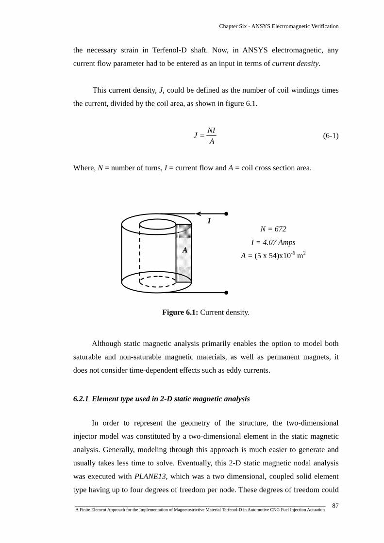
Chapter Six - ANSYS Electromagnetic Verification
the necessary strain in Terfenol-D shaft. Now, in ANSYS electromagnetic, any
current flow parameter had to be entered as an input in terms of current density.
This current density, J, could be defined as the number of coil windings times
the current, divided by the coil area, as shown in figure 6.1.
A
NIJ = (6-1)
Where, N = number of turns, I = current flow and A = coil cross section area.
N = 672
I = 4.07 Amps
A = (5 x 54)x10-6 m2
Figure 6.1: Current density.
A
I
Although static magnetic analysis primarily enables the option to model both
saturable and non-saturable magnetic materials, as well as permanent magnets, it
does not consider time-dependent effects such as eddy currents.
6.2.1 Element type used in 2-D static magnetic analysis
In order to represent the geometry of the structure, the two-dimensional
injector model was constituted by a two-dimensional element in the static magnetic
analysis. Generally, modeling through this approach is much easier to generate and
usually takes less time to solve. Eventually, this 2-D static magnetic nodal analysis
was executed with PLANE13, which was a two dimensional, coupled solid element
type having up to four degrees of freedom per node. These degrees of freedom could
_______________________________________________________________________________________________________________ A Finite Element Approach for the Implementation of Magnetostrictive Material Terfenol-D in Automotive CNG Fuel Injection Actuation
87

Chapter Six - ANSYS Electromagnetic Verification
be magnetic vector potential (AZ), displacements, temperature or time-integrated
electric potential. Furthermore, PLANE13 had a 2-D magnetic, thermal, electrical,
piezoelectric and structural field capability with limited coupling between the fields.
The shape or characteristics of PLANE13 could either be a 4-node quadrilateral or
3-node triangular, as shown in figure 6.2. In this simulation problem, however, the
4-node quadrilateral shape was preferred.
4-node quadrilateral 3-node
triangular
Figure 6.2: PLANE13 element type geometry with
nodes I, J, K and L.
L K
J I
Element coordinate system
K, L Y
(or axial)
I J
X (or radial)
PLANE13 also featured nonlinear magnetic capability for modeling B-H curve
which facilitated in defining Terfenol-D non-linear B-H material property.
Furthermore, according to PLANE13 element type input characteristics, it did not
require defining any real constants in ANSYS Electromagnetic interface.
6.2.2 Magnetic formulation
ANSYS Electromagnetic offers several formulations, depending on the type of
analysis, the material properties and the overall characteristics of the analysis.
ANSYS supports two nodal-based formulation methods; (a) the magnetic scalar
potential (MSP) formulation, and (b) the magnetic vector potential (MVP)
formulation. Where MSP formulation is appropriate only for most 3-D static analysis
applications, MVP formulation is preferable for both 2-D and 3-D dimensions with
static, harmonic and transient analysis types. Furthermore, MVP formulation has
_______________________________________________________________________________________________________________ A Finite Element Approach for the Implementation of Magnetostrictive Material Terfenol-D in Automotive CNG Fuel Injection Actuation
88
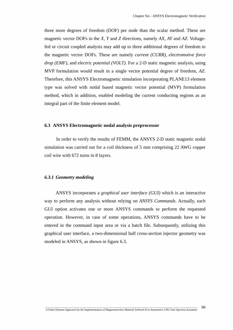
Chapter Six - ANSYS Electromagnetic Verification
three more degrees of freedom (DOF) per node than the scalar method. These are
magnetic vector DOFs in the X, Y and Z directions, namely AX, AY and AZ. Voltage-
fed or circuit coupled analysis may add up to three additional degrees of freedom to
the magnetic vector DOFs. These are namely current (CURR), electromotive force
drop (EMF), and electric potential (VOLT). For a 2-D static magnetic analysis, using
MVP formulation would result in a single vector potential degree of freedom, AZ.
Therefore, this ANSYS Electromagnetic simulation incorporating PLANE13 element
type was solved with nodal based magnetic vector potential (MVP) formulation
method, which in addition, enabled modeling the current conducting regions as an
integral part of the finite element model.
6.3 ANSYS Electromagnetic nodal analysis preprocessor
In order to verify the results of FEMM, the ANSYS 2-D static magnetic nodal
simulation was carried out for a coil thickness of 5 mm comprising 22 AWG copper
coil wire with 672 turns in 8 layers.
6.3.1 Geometry modeling
ANSYS incorporates a graphical user interface (GUI) which is an interactive
way to perform any analysis without relying on ANSYS Commands. Actually, each
GUI option activates one or more ANSYS commands to perform the requested
operation. However, in case of some operations, ANSYS commands have to be
entered in the command input area or via a batch file. Subsequently, utilizing this
graphical user interface, a two-dimensional half cross-section injector geometry was
modeled in ANSYS, as shown in figure 6.3.
_______________________________________________________________________________________________________________ A Finite Element Approach for the Implementation of Magnetostrictive Material Terfenol-D in Automotive CNG Fuel Injection Actuation
89

Chapter Six - ANSYS Electromagnetic Verification
1020 steel AWG coil
Terfenol-D 316 stainless steel Air gap
Line plot Area plot
Figure 6.3: 2-D cross-sectional geometry in ANSYS showing line and area plot.
6.3.2 Defining element type and material properties
As discussed earlier, the 2-D static magnetic nodal analysis was executed with
PLANE13 which was a two dimensional, quadrilateral, coupled solid element type
having four nodes with up to four degrees of freedom per node. The element
behavior was set as axisymmetric, as shown in figure 6.4.
_______________________________________________________________________________________________________________ A Finite Element Approach for the Implementation of Magnetostrictive Material Terfenol-D in Automotive CNG Fuel Injection Actuation
90

Chapter Six - ANSYS Electromagnetic Verification
Figure 6.4: Defining PLANE13 element type.
In order to assign the material properties, the material model behaviors for
1020 steel, 316 stainless steel, air gap and AWG copper wire were defined based on
the constant relative permeability (MURX) values of the corresponding materials.
However, for Terfenol-D, the non-linear B-H characteristics were assigned as the
material model properties, as shown in figure 6.5.
(a) (b)
Figure 6.5: (a) Defining material model behavior, (b) Terfenol-D B-H data input.
_______________________________________________________________________________________________________________ A Finite Element Approach for the Implementation of Magnetostrictive Material Terfenol-D in Automotive CNG Fuel Injection Actuation
91

Chapter Six - ANSYS Electromagnetic Verification
In this context, table 6.1 explains the assigned materials against their model numbers.
Table 6.1: Assigned material model number in ANSYS
Material model number
in ANSYS Assigned materials
1 1020 Steel
2 Terfenol-D
3 316 Stainless Steel
4 Copper
5 Air
6.3.3 Meshed geometry
Meshing is a fundamental part of the finite element analysis process, which
influences the accuracy, convergence and rapidity of the solution process. ANSYS
provides powerful tools for mesh generation irrespective of the geometry, element
type, analysis characteristics and application.
Subsequent to creating the geometry and defining the material models, each
area representing corresponding material properties were attributed with respective
material number and element type, as shown in figure 6.6. Then after implementing
the mesh size controls for the corresponding material areas, a quadratic mesh was
generated throughout the injector cross-sectional area, as shown in figure 6.7.
Figure 6.6: Defining mesh attributes by area.
_______________________________________________________________________________________________________________ A Finite Element Approach for the Implementation of Magnetostrictive Material Terfenol-D in Automotive CNG Fuel Injection Actuation
92
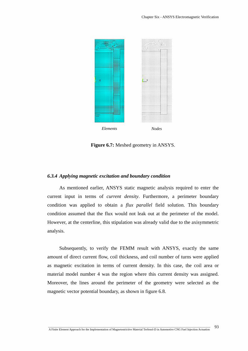
Chapter Six - ANSYS Electromagnetic Verification
Elements
Nodes
Figure 6.7: Meshed geometry in ANSYS.
6.3.4 Applying magnetic excitation and boundary condition
As mentioned earlier, ANSYS static magnetic analysis required to enter the
current input in terms of current density. Furthermore, a perimeter boundary
condition was applied to obtain a flux parallel field solution. This boundary
condition assumed that the flux would not leak out at the perimeter of the model.
However, at the centerline, this stipulation was already valid due to the axisymmetric
analysis.
Subsequently, to verify the FEMM result with ANSYS, exactly the same
amount of direct current flow, coil thickness, and coil number of turns were applied
as magnetic excitation in terms of current density. In this case, the coil area or
material model number 4 was the region where this current density was assigned.
Moreover, the lines around the perimeter of the geometry were selected as the
magnetic vector potential boundary, as shown in figure 6.8.
_______________________________________________________________________________________________________________ A Finite Element Approach for the Implementation of Magnetostrictive Material Terfenol-D in Automotive CNG Fuel Injection Actuation
93

Chapter Six - ANSYS Electromagnetic Verification
Figure 6.8: Applying current density and boundary condition.
Current density
Perimeter BC
6.4 ANSYS Electromagnetic results
Subsequently, the ANSYS 2-D static magnetic simulation was run with nodal
based Magnetic Vector Potential (MVP) formulation, as shown in figure 6.9.
Figure 6.9: Magnetostatic options and solutions.
_______________________________________________________________________________________________________________ A Finite Element Approach for the Implementation of Magnetostrictive Material Terfenol-D in Automotive CNG Fuel Injection Actuation
94

Chapter Six - ANSYS Electromagnetic Verification
Figure 6.10 shows the 2D flux lines and flux density vector sum generated from
ANSYS post-processor.
(a)
(b)
Figure 6.10: (a) 2D flux lines; (b) Flux density vector sum nodal solution.
The resultant flux density vector sum represented the magnitude of flux
density generated at each node without averaging the results across material
discontinuities. Furthermore, figure 6.11 shows the flux density distribution
throughout the entire injector actuator by producing a half (½) expanded plot
representation based on the defined axisymmetry.
_______________________________________________________________________________________________________________ A Finite Element Approach for the Implementation of Magnetostrictive Material Terfenol-D in Automotive CNG Fuel Injection Actuation
95

Chapter Six - ANSYS Electromagnetic Verification
Figure 6.11: Flux density vector sum vector plot for 2D ½ expansion.
(a) (b)
Figure 6.12: Electromagnetic force calculation, (a) Nodal solution, and (b) Vector plot.
_______________________________________________________________________________________________________________ A Finite Element Approach for the Implementation of Magnetostrictive Material Terfenol-D in Automotive CNG Fuel Injection Actuation
96
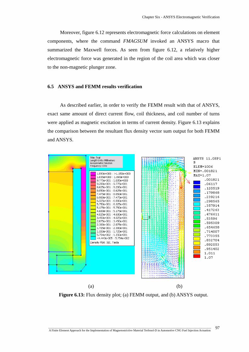
Chapter Six - ANSYS Electromagnetic Verification
Moreover, figure 6.12 represents electromagnetic force calculations on element
components, where the command FMAGSUM invoked an ANSYS macro that
summarized the Maxwell forces. As seen from figure 6.12, a relatively higher
electromagnetic force was generated in the region of the coil area which was closer
to the non-magnetic plunger zone.
6.5 ANSYS and FEMM results verification
As described earlier, in order to verify the FEMM result with that of ANSYS,
exact same amount of direct current flow, coil thickness, and coil number of turns
were applied as magnetic excitation in terms of current density. Figure 6.13 explains
the comparison between the resultant flux density vector sum output for both FEMM
and ANSYS.
(a) (b)
Figure 6.13: Flux density plot; (a) FEMM output, and (b) ANSYS output.
_______________________________________________________________________________________________________________ A Finite Element Approach for the Implementation of Magnetostrictive Material Terfenol-D in Automotive CNG Fuel Injection Actuation
97

Chapter Six - ANSYS Electromagnetic Verification
Figure 6.14 explains the flux density distribution along the three different
contour lines. As seen from the figure 6.14, the flux density distribution stays more
or less uniform along the different contour regions, implying no major fluctuations of
flux density along the Terfenol-D member resulting in maximum possible strain
output.
Figure 6.14: Flux density distribution along the indicated contour lines.
(0,0) (15,0)
(15,-10) (0,-10)
(0,10) (15,10)
Table 6.2: Percentage error calculation for FEMM and ANSYS flux density output.
Average flux density, Tesla (T) Contour lines
(r1,z1) to (r2,z2) FEMM Results ANSYS ResultsPercentage Error (%)
(0,10) to (15,10) 0.60752 0.55430 9.6%
(0,0) to (15,0) 0.55867 0.52626 6.15%
(0,-10) to (15,-10) 0.47762 0.45655 4.61%
Table 6.2 explains the percentage error between the FEMM and ANSYS
average flux density output. Although the analysis showed the derived percentage
errors in case of the average flux density output, considering mesh variance and
element type difference between ANSYS and FEMM simulation environments, these
simulation results could be treated as satisfactory.
_______________________________________________________________________________________________________________ A Finite Element Approach for the Implementation of Magnetostrictive Material Terfenol-D in Automotive CNG Fuel Injection Actuation
98

Chapter Six - ANSYS Electromagnetic Verification
6.6 Summary of chapter six
The purpose of this chapter was to verify the results obtained from FEMM with
ANSYS. Eventually, according to the verified results, for a coil thickness of 5 mm
with 22 AWG wire having 672 turns in 8 layers, possessed good prospect in actuating
the desired amount of injector lift of 50 microns as the required magnetic field
strength was achieved to cause the necessary amount of magnetostrictive strain. A
concise and inclusive overview of the highlighted research process of this chapter is
shown in figure 6.15.
_______________________________________________________________________________________________________________ A Finite Element Approach for the Implementation of Magnetostrictive Material Terfenol-D in Automotive CNG Fuel Injection Actuation
99
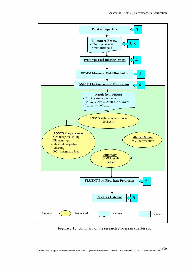
Chapter Six - ANSYS Electromagnetic Verification
1 Point of Departure
Literature Review - CNG fuel injection - Smart materials
Prototype Fuel Injector Design
FEMM Magnetic Field Simulation
ANSYS Electromagnetic Verification
Research Outcome
FLUENT Fuel Flow Rate Prediction
Result from FEMM
Resource Research task
- Coil thickness, t = 5 mm - 22 AWG with 672 turns in 8 layers - Current = 4.07 amps
2, 3
4
5
6
7
8
ANSYS static magnetic nodal analysis
ANSYS Solver MVP formulation
Summary FEMM result
verified
ANSYS Pre-processor - Geometry modelling - Element type - Material properties - Meshing - BC & magnetic load
Legend: Sequence
Figure 6.15: Summary of the research process in chapter six.
_______________________________________________________________________________________________________________ A Finite Element Approach for the Implementation of Magnetostrictive Material Terfenol-D in Automotive CNG Fuel Injection Actuation
100

CHAPTER SEVEN
CNG FUEL INJECTOR MASS
FLOW RATE PREDICTION BY
FLUENT

Chapter Seven - CNG Fuel Injector Mass Flow Rate Prediction by FLUENT
7.1 Introduction
Computational fluid dynamics (CFD) is one of the branches of fluid mechanics
that uses numerical methods and algorithms to solve and analyze problems that
involve fluid flow utilizing computer software [124]. The advent of high speed and
large memory computers has enabled users to obtain solutions to many flow
problems such as compressible or incompressible, potential or non-potential, laminar
or turbulent, multiphase and chemically reacting or non-reacting [125]. In case of the
fluid flow problems, the governing equations such as continuity (conservation of
mass), the Navier-Stokes (conservation of momentum), species and energy equations
makeup a system of coupled non-linear partial differential equations [124,125].
However, due to the non-linearity of these partial differential equations, the
analytical methods yield a small number of solutions. Furthermore, in order to obtain
closed from analytical solutions, the partial differential equations need to be made
linear or higher orders of linearity are neglected. Therefore, numerical methods need
to be implemented in most engineering flow simulations where the non-linearity
cannot be neglected. In this context, CFD replaces the partial differential equations
governing the fluid flow with algebraic equations, which in turn can be solved with
the assistance of a digital computer to get an approximate solution [126].
In CFD analysis, various discretization methods are implemented in order to
transfer continuous models and equations into discrete counterparts. These are
mainly, finite difference method (FDM), finite volume method (FVM), finite element
method (FEM) and boundary element method (BEM) [127,128]. In this case, the
software that was utilized in order to simulate the mass flow rate of CNG was
FLUENT Inc. version 6.2.16, which employed the FVM method. This FVM method
featured the benefit of allowing direct discretization in the physical space without the
necessity of an explicit computation of metric co-efficient for arbitrary mesh
configuration.
_______________________________________________________________________________________________________________ A Finite Element Approach for the Implementation of Magnetostrictive Material Terfenol-D in Automotive CNG Fuel Injection Actuation
101

Chapter Seven - CNG Fuel Injector Mass Flow Rate Prediction by FLUENT
7.2 Turbulence models
In order to solve various fluid problems, a number of turbulence models are
generally available. However, no single turbulence model is universally accepted as a
superior model for all classes of problems. The choice of turbulence model generally
depends on conditions such as the physics encompassed in the flow, the established
practice for a specific class of problem, the level of accuracy required, the available
computational resources and the amount of time available for the simulation.
Furthermore, in order to make the most appropriate choice of model for a certain
application, the user needs to understand the capabilities and limitations of the
various models [127,129]. The different types of turbulence models are as follows
[128-130]:
• Spalart-Allmaras model
• k − ε models
Standard k − ε model
Renormalization-group (RNG) k − ε model
Realizable k − ε model
• k − ω models
Standard k − ω model
Shear-stress transport (SST) k − ω model
• ν 2 − f model
• Reynolds stress model (RSM)
• Large eddy simulations (LES) model
In the present study, the Standard k − ε, the Realizable k − ε and RSM models
were utilized for the modeling of the CNG flow conduit to predict the mass flow rate
of CNG for the injector lift of 50 microns.
7.2.1 The Standard k − ε model
The standard k − ε model is the simplest, fastest and most validated model for
turbulence proposed by Launder and Spalding [131], which brings the solution of
_______________________________________________________________________________________________________________ A Finite Element Approach for the Implementation of Magnetostrictive Material Terfenol-D in Automotive CNG Fuel Injection Actuation
102
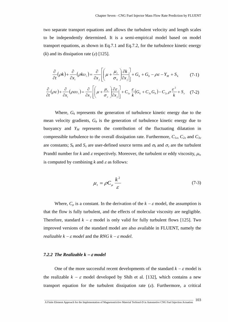
Chapter Seven - CNG Fuel Injector Mass Flow Rate Prediction by FLUENT
two separate transport equations and allows the turbulent velocity and length scales
to be independently determined. It is a semi-empirical model based on model
transport equations, as shown in Eq.7.1 and Eq.7.2, for the turbulence kinetic energy
(k) and its dissipation rate (ε) [125].
( ) ( ) kMbkjk
t
ji
i
SYGGxk
xk
xk
t+−−++
⎥⎥⎦
⎤
⎢⎢⎣
⎡
∂∂
⎟⎟⎠
⎞⎜⎜⎝
⎛+
∂∂
=∂∂
+∂∂ ρε
σμ
μυρρ (7-1)
( ) ( ) ( ) εεεεε
ερεεσμ
μρευρε Sk
CGCGk
Cxxxt bk
j
t
ji
i
+−++⎥⎥⎦
⎤
⎢⎢⎣
⎡
∂∂
⎟⎟⎠
⎞⎜⎜⎝
⎛+
∂∂
=∂∂
+∂∂ 2
231 (7-2)
Where, Gk represents the generation of turbulence kinetic energy due to the
mean velocity gradients, Gb is the generation of turbulence kinetic energy due to
buoyancy and YM represents the contribution of the fluctuating dilatation in
compressible turbulence to the overall dissipation rate. Furthermore, C1ε, C2ε and C3ε
are constants; Sk and Sε are user-defined source terms and σk and σε are the turbulent
Prandtl number for k and ε respectively. Moreover, the turbulent or eddy viscosity, μt,
is computed by combining k and ε as follows:
ε
ρμ μ
2kCt = (7-3)
Where, Cμ is a constant. In the derivation of the k − ε model, the assumption is
that the flow is fully turbulent, and the effects of molecular viscosity are negligible.
Therefore, standard k − ε model is only valid for fully turbulent flows [125]. Two
improved versions of the standard model are also available in FLUENT, namely the
realizable k − ε model and the RNG k − ε model.
7.2.2 The Realizable k − ε model
One of the more successful recent developments of the standard k − ε model is
the realizable k − ε model developed by Shih et al. [132], which contains a new
transport equation for the turbulent dissipation rate (ε). Furthermore, a critical
_______________________________________________________________________________________________________________ A Finite Element Approach for the Implementation of Magnetostrictive Material Terfenol-D in Automotive CNG Fuel Injection Actuation
103

Chapter Seven - CNG Fuel Injector Mass Flow Rate Prediction by FLUENT
coefficient of the model, Cμ , is expressed as a function of mean flow and turbulence
properties, rather than assumed to be constant as in the standard model. The one
limitation of the realizable k − ε model is that it produces non-physical turbulent
viscosities when the computational domain contains both rotating and stationary
fluid zones. However, in case of spray models, this model provides satisfactory
results [132].
7.2.3 The Reynolds Stress Model (RSM)
The RSM is the most classical model based on the initial work of Launder
[131], which solves the transport equations for the Reynolds stresses together with an
equation for the dissipation rate. Which eventually means that five additional
transport equations are required in 2D flows and seven additional transport equations
must be solved in case of 3D problems. The RSM model has a greater potential to
represent turbulent flow phenomena more correctly than the two other models.
However, it takes more computational time and is slow to converge [133].
7.3 Modeling of the CNG conduit
In the present research, a three dimensional replica of the CNG flow conduit
was modeled in GAMBIT with the resultant injector lift of 50 Microns. For the CFD
analysis, the following steps were implemented;
Geometry creation
Specifying zone types
Meshing
FLUENT Solver
7.3.1 Geometry creation
The 3D geometry of the CNG flow conduit was created in the Pro-Engineer
Wildfire 3.0 which was then imported in Gambit version 2.4.6 as IGES format. The
_______________________________________________________________________________________________________________ A Finite Element Approach for the Implementation of Magnetostrictive Material Terfenol-D in Automotive CNG Fuel Injection Actuation
104

Chapter Seven - CNG Fuel Injector Mass Flow Rate Prediction by FLUENT
Gambit allows geometry to be constructed or imported from alternative packages as
different formats, such as ACIS, IGES, STEP, Parasolid, Catia and CAD with
cleanup and modification capabilities.
Figure 7.1: Pro-Engineer model of the CNG flow conduit.
Hollow Conduit
Solid Conduit
CNG Inlet
CNG Outlet
The Pro-E 3D solid model of the CNG flow conduit was constructed from the
inner hollow channel of the original injector assembly having the same dimensions,
as shown in figure 7.1. The Pro-E part file was then imported as IGES format in
GAMBIT, as shown in figure 7.2.
_______________________________________________________________________________________________________________ A Finite Element Approach for the Implementation of Magnetostrictive Material Terfenol-D in Automotive CNG Fuel Injection Actuation
105

Chapter Seven - CNG Fuel Injector Mass Flow Rate Prediction by FLUENT
Figure 7.2: Importing Pro-E model as IGES in GAMBIT
Eventually the model was cleaned by using Virtual Cleanup tool in GAMBIT.
Furthermore, specifying the No-stand alone edges in the Stand-alone Geometry
option enabled GAMBIT not to read in any edges that do not belong to faces or
volumes. Fig.7.3 shows the imported geometry in GAMBIT graphical user interface.
Figure 7.3: Imported CNG flow conduit model in GAMBIT.
_______________________________________________________________________________________________________________ A Finite Element Approach for the Implementation of Magnetostrictive Material Terfenol-D in Automotive CNG Fuel Injection Actuation
106

Chapter Seven - CNG Fuel Injector Mass Flow Rate Prediction by FLUENT
In this research, FLUENT 5/6 solver was selected in GAMBIT version 2.4.6 for CFD
analysis.
7.3.2 Specifying zone types
Zone-type specifications define the physical and operational characteristics of
the model at its boundaries and within specific regions of its domain. There are two
classes of zone-type specifications, namely Boundary types and Continuum types.
Where Boundary-type specifications defined the physical and operational
characteristics of the model at those topological entities that represent model
boundaries, Continuum-type specifications defined the physical characteristics of the
model within specified regions of its domain. In this research, the CNG inlet and
CNG outlet face regions were consecutively defined as pressure inlet and pressure
outlet boundary types. Furthermore the rest of the faces were defined as wall
boundary type and the volume was defined as the continuum type. In this regard,
table 7.1 describes all the zone type specifications.
Table 7.1: Zone type specifications
Entity Zone Zone Type
face.8 Boundary PRESSURE_INLET
face.1
face.17 Boundary PRESSURE_OUTLET
face.(2-7)
face (9-16)Boundary WALL
volume.1 Continuum FLUID
7.3.3 Meshing
The meshing of the model geometry is an important and challenging task
because the quality of the mesh affects the accuracy of the solution, the CPU time
and memory requirements [134]. In this simulation, the Mesh Volumes command
_______________________________________________________________________________________________________________ A Finite Element Approach for the Implementation of Magnetostrictive Material Terfenol-D in Automotive CNG Fuel Injection Actuation
107

Chapter Seven - CNG Fuel Injector Mass Flow Rate Prediction by FLUENT
allowed to create the mesh for the entire volume of the model. When meshing the
volume, GAMBIT created mesh nodes throughout the volume according to the
specified meshing parameters. In order to specify the meshing scheme, two
parameters were defined. These are Elements and Type.
The Elements parameter defined the shape of the elements that were used to
mesh the volume. In this case, a Tet/Hybrid element type was chosen which specified
that the mesh was composed primarily of tetrahedral mesh elements but may include
hexahedral, pyramidal and wedge elements where appropriate. Subsequently, the
TGrid type was associated with the Tet/Hybrid element type. The TGrid meshing
scheme enabled GAMBIT to create an array of pyramidal mesh elements in
proximity of the faces and furthermore creating tetrahedral elements throughout the
rest of the volume. The meshed geometry is shown in figure 7.4.
Figure 7.4: Meshed geometry in GAMBIT.
_______________________________________________________________________________________________________________ A Finite Element Approach for the Implementation of Magnetostrictive Material Terfenol-D in Automotive CNG Fuel Injection Actuation
108
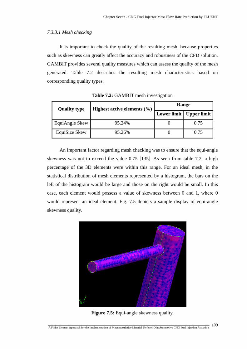
Chapter Seven - CNG Fuel Injector Mass Flow Rate Prediction by FLUENT
7.3.3.1 Mesh checking
It is important to check the quality of the resulting mesh, because properties
such as skewness can greatly affect the accuracy and robustness of the CFD solution.
GAMBIT provides several quality measures which can assess the quality of the mesh
generated. Table 7.2 describes the resulting mesh characteristics based on
corresponding quality types.
Table 7.2: GAMBIT mesh investigation
Range Quality type Highest active elements (%)
Lower limit Upper limit
EquiAngle Skew 95.24% 0 0.75
EquiSize Skew 95.26% 0 0.75
An important factor regarding mesh checking was to ensure that the equi-angle
skewness was not to exceed the value 0.75 [135]. As seen from table 7.2, a high
percentage of the 3D elements were within this range. For an ideal mesh, in the
statistical distribution of mesh elements represented by a histogram, the bars on the
left of the histogram would be large and those on the right would be small. In this
case, each element would possess a value of skewness between 0 and 1, where 0
would represent an ideal element. Fig. 7.5 depicts a sample display of equi-angle
skewness quality.
Figure 7.5: Equi-angle skewness quality.
_______________________________________________________________________________________________________________ A Finite Element Approach for the Implementation of Magnetostrictive Material Terfenol-D in Automotive CNG Fuel Injection Actuation
109

Chapter Seven - CNG Fuel Injector Mass Flow Rate Prediction by FLUENT
7.3.4 FLUENT solver
The FLUENT 6.2.16 solver provides comprehensive modeling capabilities for
a wide range of compressible and incompressible, laminar and turbulent fluid flow
problems. Generally, two numerical methods are utilized to solve the fluid flow
problems. These are namely, coupled solver and segregated solver. The coupled
solver solves the governing equations of continuity, momentum and energy and
species transport simultaneously. Where as, the segregated solver algorithm solves
governing equations sequentially in order to obtain the solution [136]. Furthermore,
each iteration follows the algorithm, shown in figure 7.6, and loops until the
convergence criteria are met. In the present research, segregated solver was used
which was fast and had less memory usage compared to coupled solver [136].
Update Properties
Solve Momentum Equations
Solve Pressure-Correction (continuity) Equation Update Pressure, Face Mass Flow Rate
Solve Energy, Species, Turbulence & other Quantities
Converged Stop
Figure 7.6: Overview of the segregated solution method [130].
_______________________________________________________________________________________________________________ A Finite Element Approach for the Implementation of Magnetostrictive Material Terfenol-D in Automotive CNG Fuel Injection Actuation
110
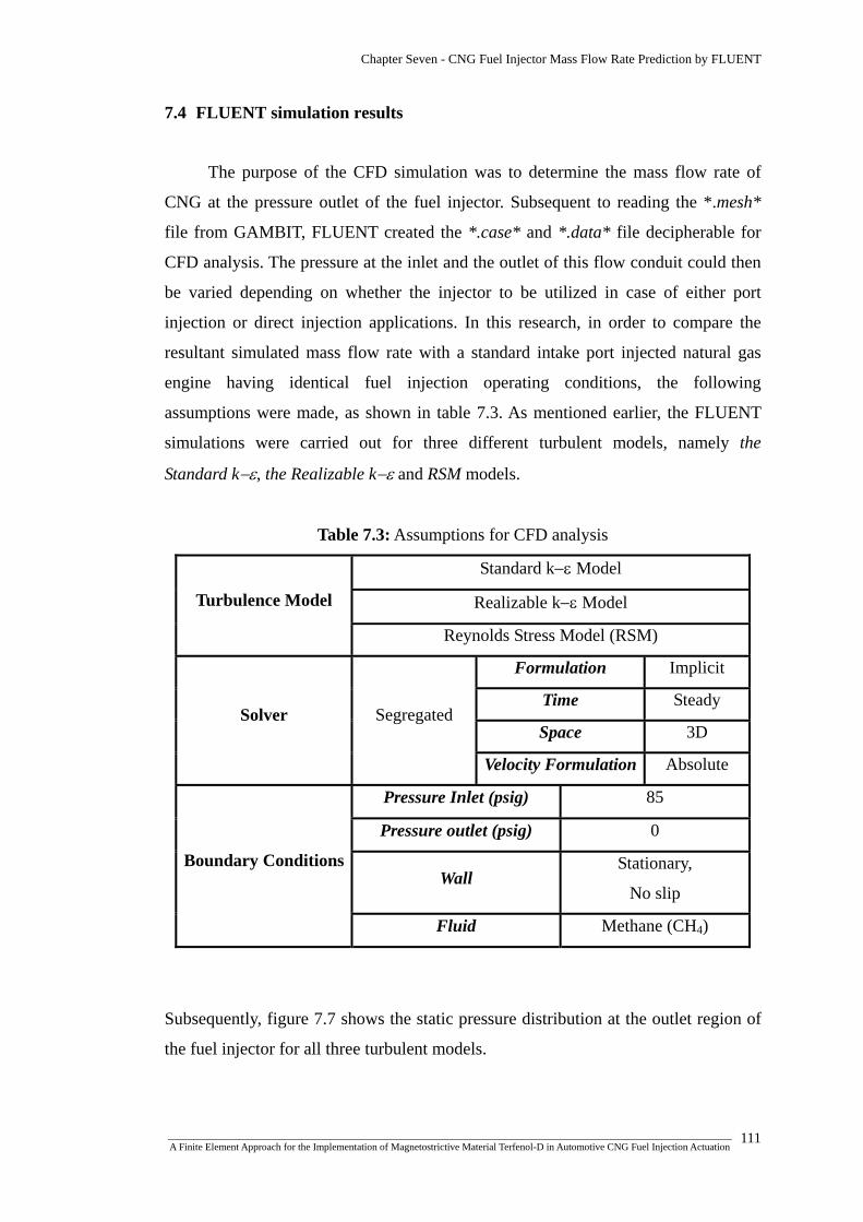
Chapter Seven - CNG Fuel Injector Mass Flow Rate Prediction by FLUENT
7.4 FLUENT simulation results
The purpose of the CFD simulation was to determine the mass flow rate of
CNG at the pressure outlet of the fuel injector. Subsequent to reading the *.mesh*
file from GAMBIT, FLUENT created the *.case* and *.data* file decipherable for
CFD analysis. The pressure at the inlet and the outlet of this flow conduit could then
be varied depending on whether the injector to be utilized in case of either port
injection or direct injection applications. In this research, in order to compare the
resultant simulated mass flow rate with a standard intake port injected natural gas
engine having identical fuel injection operating conditions, the following
assumptions were made, as shown in table 7.3. As mentioned earlier, the FLUENT
simulations were carried out for three different turbulent models, namely the
Standard k−ε, the Realizable k−ε and RSM models.
Table 7.3: Assumptions for CFD analysis
Standard k−ε Model
Realizable k−ε Model Turbulence Model
Reynolds Stress Model (RSM)
Formulation Implicit
Time Steady
Space 3D Solver Segregated
Velocity Formulation Absolute
Pressure Inlet (psig) 85
Pressure outlet (psig) 0
Wall Stationary,
No slip
Boundary Conditions
Fluid Methane (CH4)
Subsequently, figure 7.7 shows the static pressure distribution at the outlet region of
the fuel injector for all three turbulent models.
_______________________________________________________________________________________________________________ A Finite Element Approach for the Implementation of Magnetostrictive Material Terfenol-D in Automotive CNG Fuel Injection Actuation
111

Chapter Seven - CNG Fuel Injector Mass Flow Rate Prediction by FLUENT
FLUENT 6.2 (3d, segregated, standard k-ε)
FLUENT 6.2 (3d, segregated, realizable k-ε)
FLUENT 6.2 (3d, segregated, RSM)
Figure 7.7: Velocity vector colored by static pressure (Pa).
_______________________________________________________________________________________________________________ A Finite Element Approach for the Implementation of Magnetostrictive Material Terfenol-D in Automotive CNG Fuel Injection Actuation
112

Chapter Seven - CNG Fuel Injector Mass Flow Rate Prediction by FLUENT
Eventually, the simulated mass flow rates at the pressure outlet of the fuel
injector for the three turbulent models are depicted in the table 7.4. However, these
values would depend on the inlet and outlet pressures of the fuel injector.
Table 7.4: Results of mass flow rates at the pressure outlet of the injector for
Pinlet: 85 psig, Poutlet: 0 psig
Turbulent model Mass flow rate
(kg/sec)
Standard k-ε 0.00527488
Realizable k-ε 0.005214056
Reynolds Stress Model (RSM) 0.005530861
7.4.1 Sample calculation of injector flow rate
The brake specific fuel consumption (BSFC) of an automotive engine is a
measure of engine efficiency expressed as the rate of fuel consumption divided by
the power produced, which could be represented as,
HorsepowerRateFlowFuelCFSB __... = (7-4)
Considering the duty cycle of the fuel injector, the required injector static flow rate at
43.5 psig was [137]:
CycleDutyNumberInjectorCFSBHorsepowerRateFlowStaticInjector psig __...___ 543 ×
×=⋅ (7-5)
Again, in order to find the new fuel flow rate after the change of fuel pressure [137]:
RateFuelOldessureOldessureNewRateFlowNew __
Pr_Pr___ ×= (7-6)
The assumptions for this calculation are shown in table 7.4.
_______________________________________________________________________________________________________________ A Finite Element Approach for the Implementation of Magnetostrictive Material Terfenol-D in Automotive CNG Fuel Injection Actuation
113

Chapter Seven - CNG Fuel Injector Mass Flow Rate Prediction by FLUENT
Table 7.4: Assumptions for sample fuel flow calculation
Entity Value Remark
B.S.F.C 0.50 For naturally aspirated engine
(0.45-0.50)
Duty Cycle 0.80 Accepted industry standard for
safe operation
Crankshaft
Horsepower (BHP) 250 Assumption
Number of Injectors 6 Assumption
Old Pressure (psig) 43.5 Functional pressure for Eq.7-5
New Pressure (psig) 85 Inlet pressure of fuel injector in
CFD analysis
Now from Eq.7-5,
psigRateFlowStaticInjector 543___ ⋅ CycleDutyNumberInjectorCFSBHorsepower__...
××
=
min
42.27304.268.06
5.0250 cchrlbs
==⎟⎠⎞
⎜⎝⎛
××
=
Again, from Eq.7.6,
RateFlowNew __ RateFuelOldessureOldessureNew __
Pr_Pr_
×=
min
20.38240.3604.265.43
85 cchrlbs
==×=
=sec
0045.0 kg
Thus, a typical fuel injector operated under the same pressure conditions as in
the case of the simulated prototype fuel injector would provide a mass flow rate of
0.0045 kg/sec. The percentage differences between the simulated and numerically
derived fuel injector mass flow rates are depicted in table 7.5:
_______________________________________________________________________________________________________________ A Finite Element Approach for the Implementation of Magnetostrictive Material Terfenol-D in Automotive CNG Fuel Injection Actuation
114

Chapter Seven - CNG Fuel Injector Mass Flow Rate Prediction by FLUENT
Table 7.5: Percentage difference between simulated and numerically derived mass
flow rate
Turbulent model
Simulated
mass flow
rate
(kg/sec)
Numerically
derived
mass flow rate
(kg/sec)
Percentage
difference
(%)
Standard k-ε 0.00527488 15.85%
Realizable k-ε 0.005214056 14.70%
Reynolds Stress Model
(RSM) 0.005530861
0.0045
20.55%
7.5 Summary of chapter seven
The purpose of the CFD analysis of the prototype fuel injector was to predict
the mass flow rate of CNG at a specific operating condition. In this research, the
analysis was performed to simulate the injection environment as if the injector was
operated in case of an inlet port fuel injection system, where a standard port operated
fuel injector inlet pressure was considered. Although the prototype injector model
successfully operated under this simulated environment, the amount of mass flow
rate at the pressure outlet was found to be slightly higher compared to the
mathematically derived one. However, the mathematical model disregarded factors
such as the cross-sectional area of injector outlet, turbulent flow and wall conditions.
A concise and inclusive overview of the highlighted research process of this chapter
is shown in figure 7.8.
_______________________________________________________________________________________________________________ A Finite Element Approach for the Implementation of Magnetostrictive Material Terfenol-D in Automotive CNG Fuel Injection Actuation
115
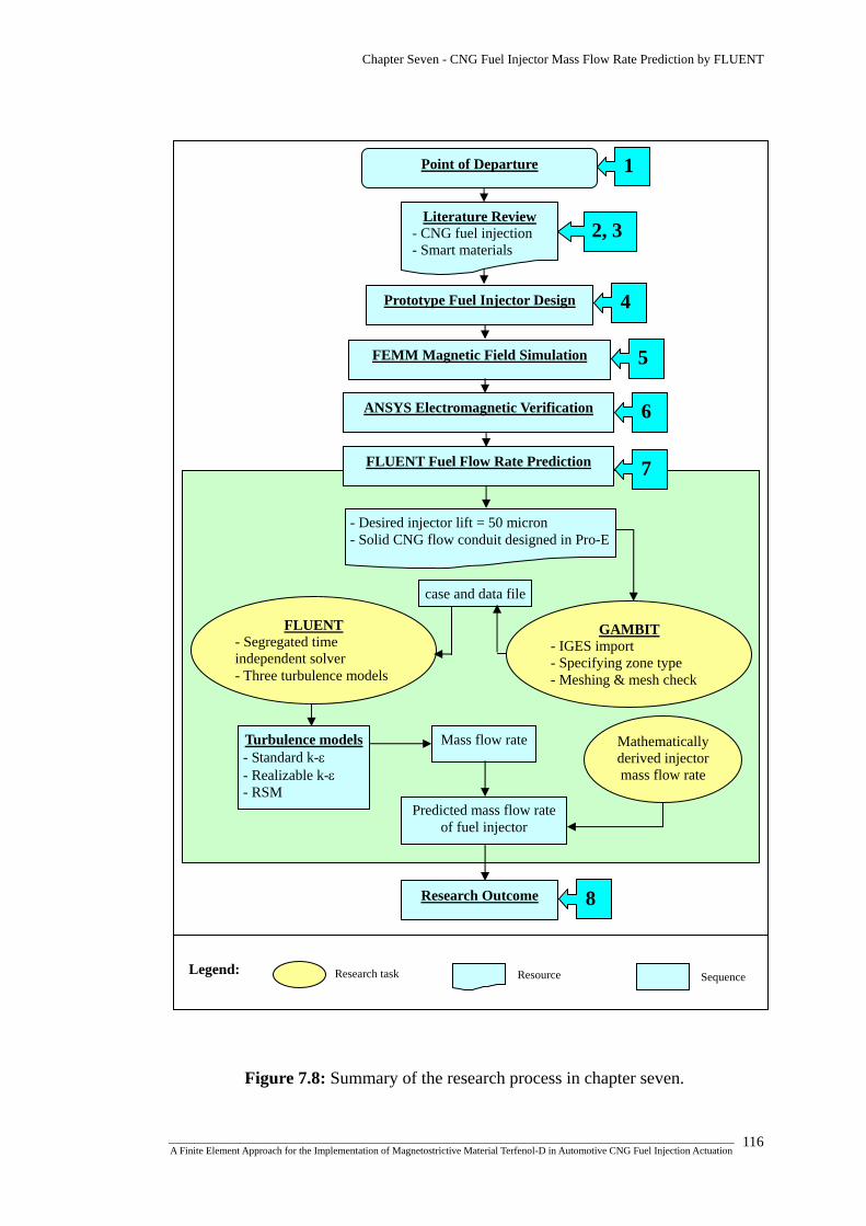
Chapter Seven - CNG Fuel Injector Mass Flow Rate Prediction by FLUENT
1
2, 3
4 Prototype Fuel Injector Design
Literature Review - CNG fuel injection - Smart materials
Point of Departure
FEMM Magnetic Field Simulation
6
5
ANSYS Electromagnetic Verification
7 FLUENT Fuel Flow Rate Prediction
- Desired injector lift = 50 micron - Solid CNG flow conduit designed in Pro-E
GAMBIT - IGES import - Specifying zone type - Meshing & mesh check
Turbulence models- Standard k-ε - Realizable k-ε - RSM
Mass flow rate Mathematically derived injector mass flow rate
Predicted mass flow rate of fuel injector
case and data file
FLUENT - Segregated time independent solver - Three turbulence models
8 Research Outcome
Research task Legend: Resource Sequence
Figure 7.8: Summary of the research process in chapter seven.
_______________________________________________________________________________________________________________ A Finite Element Approach for the Implementation of Magnetostrictive Material Terfenol-D in Automotive CNG Fuel Injection Actuation
116

CHAPTER EIGHT
CONCLUSIONS
&
RECOMMENDATIONS
Chapter Eight - Conclusions & Recommendations
8.1 Conclusions
In order to harness the exquisite properties of magnetostrictive material
Terfenol-D in automotive CNG fuel injection actuation, a prototype CNG fuel
injector was designed utilizing Terfenol-D as the actuator material. The research
successfully demonstrated the prospect for implementing such materials in
automotive fuel injection system through electromagnetic and computational fluid
dynamics simulations. Although the present solenoid fuel injection systems suffer
due to lack of actuator response time resulting in poor control of fuel injection at
moderate to high speed levels, prospects for implementing magnetostrictive materials
in these systems would still be less due to high cost involved in their production.
Therefore, further attention should be given towards the monetary value regarding
the production of these materials for more practical usage and also to achieve better
fuel injection control, thereby minimizing the environmental pollution. The
conclusions of the study could be summarized as follows:
a) Fuel injector design: A prototype CNG fuel injector assembly was designed
using Pro-Engineer. The new design primarily included magnetostrictive material
Terfenol-D as the actuator material, 1020 Steel having soft magnetic properties as the
injector housing material, AWG copper wire as the coil material and 316 Stainless
Steel having non-magnetic properties as the plunger material. While a Coil spring
was designed to act as the closing spring having the task of bringing the needle valve
to a closed position, a Belleville spring was designed as the prestress spring which
had the task of providing axial prestress to the Terfenol-D shaft.
b) FEMM magnetic field simulation: After determining the required flux
density of 0.55 Tesla for 1 KSI prestress to achieve the desired injector lift of 50
microns, a 2D cross-sectional geometry including the injector housing, coil,
Terfenol-D shaft, and plunger, was modelled in Finite Element Method Magnetics
(FEMM) for 2D axisymmetric magnetic simulation. The material models comprised
the real linear or non-linear magnetic properties of the corresponding materials. The
FEMM magnetostatic series circuit simulations were carried out with 22, 24, 28 and
30 AWG coil wires and for injector coil thicknesses of 2, 3, 4 and 5 mm in order to
_______________________________________________________________________________________________________________ A Finite Element Approach for the Implementation of Magnetostrictive Material Terfenol-D in Automotive CNG Fuel Injection Actuation
117

Chapter Eight - Conclusions & Recommendations
evaluate the relationship between the different coil types and thicknesses against the
achieved strain or injector lift. After analyzing the results, for the coil thickness of 5
mm, 22 AWG with 672 numbers of turns in 8 layers showed superior prospect in
actuating the desired amount of injector lift.
Furthermore, the FEMM magnetostatic parallel circuit simulations showed that
higher parallel circuit current and lower parallel circuit voltage were required to
achieve the desired flux density of 0.55 Tesla, while the coil power remained
identical in both cases. Moreover, the FEMM time-harmonic series circuit
simulations demonstrated that the flux density tended to increase suddenly for the
same amount of current flow as the frequency was increased. However, as the
frequency was increased further, the average value of flux density tended to decrease
again.
c) ANSYS electromagnetic verification: The results obtained from FEMM
simulation were verified by ANSYS electromagnetic simulation software. The
analysis showed some slight variations in case of the average flux density output.
However, these variations might be due to the mesh variance and element type
difference between ANSYS and FEMM simulation environments.
d) Injector mass flow rate prediction by FLUENT: A three dimensional
replica of the CNG flow conduit was modelled in GAMBIT with the resultant injector
lift of 50 microns. The meshed conduit was then simulated in FLUENT using the 3D
time independent segregated solver with standard k-ε, realizable k-ε and RSM
turbulent models to predict the mass flow rate of CNG to be injected, which showed
successful injector function under these simulation environments. Eventually, the
simulated flow rates were verified against mathematically derived static flow rate
required for a standard automotive fuel injector, which showed that the amount of
mass flow rate at the pressure outlet was slightly higher for the CFD models
compared to the mathematically derived one. However, the mathematical model
disregarded factors such as the cross-sectional area of injector outlet, turbulent flow
and wall conditions.
_______________________________________________________________________________________________________________ A Finite Element Approach for the Implementation of Magnetostrictive Material Terfenol-D in Automotive CNG Fuel Injection Actuation
118

Chapter Eight - Conclusions & Recommendations
8.2 Contributions of the thesis
The exquisite magnetostrictive actuating capabilities at micron scale and the
incompetence of traditional solenoid fuel injection system motivated this research to
contribute towards developing an automotive fuel injection system actuated by
magnetostrictive material Terfenol-D. In this context, the electromagnetic and
computational fluid dynamics analyses confirmed the possibility of developing such
an actuator for fuel injection actuation. Consequently, the contributions of the thesis
could be summarized as follows:
The thesis contributed in designing a prototype automotive compressed natural
gas fuel injector with the magnetostrictive material Terfenol-D as the actuator.
The thesis contributed in establishing the capability of actuating such an injector
by providing the coil-circuit parameters required to achieve a specific
magnetostrictive strain resulting in an injector lift.
The thesis contributed in establishing the capability of the prototype fuel injector
in case of injecting compressed natural gas fuel at regular mass flow rates.
8.3 Recommendations for future work
The simulation results of this thesis have provided substantial groundwork for
developing a CNG fuel injector actuated by magnetostrictive material Terfenol-D for
practical implementation. Consequently, some recommendations for the future work
regarding further development and construction of such an injector are as follows:
Further investigation in verifying the produced magnetostrictive strain by
constructing a test rig, where the strain could be measured directly by laser
displacement sensor.
Further investigation regarding the transient response of the prototype fuel
injector.
_______________________________________________________________________________________________________________ A Finite Element Approach for the Implementation of Magnetostrictive Material Terfenol-D in Automotive CNG Fuel Injection Actuation
119

Chapter Eight - Conclusions & Recommendations
Further investigation regarding developing the fuel injector control circuit.
Further investigation regarding the determination of spring forces required in
case of both closing and pre-stress spring for practical implementation.
8.4 Summary of chapter eight
The summary of research outcome is shown in figure 8.1. Point of Departure
2, 3
1
Literature Review - CNG fuel injection - Smart materials
4 Prototype Fuel Injector Design
FEMM Magnetic Field Simulation 5
ANSYS Electromagnetic Verification
7
6
FLUENT Fuel Flow Rate Prediction
Research Outcome
Conclusions
Injector design
FEMM simulation
ANSYS verification
Injector mass flow rate prediction by FLUENT
8
Contributions
Prototype fuel injector design
Providing coil-circuit parameters to inject
Capability of injecting at regular mass flow rates
Future work
Sequence Resource Legend: Research task
Figure 8.1: Summary of the research process in chapter eight.
_______________________________________________________________________________________________________________ A Finite Element Approach for the Implementation of Magnetostrictive Material Terfenol-D in Automotive CNG Fuel Injection Actuation
120

REFERENCES

References
[1] Natural Gas Vehicle Technology, http://engva.org, accessed 10/07/06. [2] J. G. Ingersoll, Natural Gas Vehicles: Economic, Environmental and
Infrastructure Strategies, Fairmont Press, Inc., Georgia, USA, ISBN 0881732184, 1995.
[3] R. Schmer, The Motor Gasoline Industry: Past, Present & Future, DIANE
Publishing, Darby, PA, USA, ISBN 0788187368, 2000. [4] B. Onursal, S. P. Gautam, Vehicular Air Pollution: Experiences from Seven
Latin American Urban Centers, World Bank Publications, Washington DC, USA, ISBN 0821340166, 1997.
[5] D. J. Podnar and J. T. Kubesh, Development of the Next Generation Medium-
Duty Natural Gas Engine, Final Report-NREL/SR-540-27503, 2000. [6] A. A. Quader, The Axially Stratified Charge Engine, SAE technical paper
820131, 1982. [7] J. T. Kubesh, Development of a Throttleless Natural Gas Engine, Final Report-
NREL/SR-540-31141, 2001. [8] G. B. Cox, K. A. DelVecchio, W. J. Hays, J. D. Hiltner, R. Nagaraj, and C.
Emmer, Development of a Direct-Injected Natural Gas Engine System for Heavy-Duty Vehicles, Final Report Phase II, NREL/SR-540-27501, 2000.
[9] S. Shiga, S. Ozone, H. T. C. Machacon, T. Karasawa, H. Nakamura, T. Ueda,
N. Jingu, Z. Huang, M. Tsue and M. Kono, A Study of the Combustion and Emission Characteristics of Compressed-Natural-Gas Direct-Injection Stratified Combustion Using a Rapid-Compression-Machine, Combustion And Flame, 2002, Vol. 129, pp 1-10.
[10] H. T. C. Machacon, T. Yamagata, H. Sekita, K. Uchiyama, S. Shiga, T.
Karasawa and H. Nakamura, JSAE Review 21, 2000, Vol. 4, p. 568. [11] T. J. Callahan and J. T. Kubesh, Contribution of Prechamber Combustion to
Engine CO and FC Emissions, Gas Machinery Conference, 1988. [12] C. Y. Liu, R. Chen and S. F. Hussain, Development of Gaseous Injector for
Propane and CNG, Part I, SAE technical paper 981355, 1998. [13] G. Thomas, J. Goulding and C. Munteanu, Measurement, Approval and
Verification of CNG Dispensers, NMSPU Project KT11 Report, www.nwml.gov.uk, accessed 10/07/06.
_______________________________________________________________________________________________________________ A Finite Element Approach for the Implementation of Magnetostrictive Material Terfenol-D in Automotive CNG Fuel Injection Actuation 121
References
[14] P. Ouellette and A. Welch, Progresses in High Pressure Direct Injection (HPDI) of Natural Gas in Automotive Diesel Engines, Proc 8th Int Conf on NGV, 2002, pp. 1-11.
[15] T. Fukuda, T. Komoda, K. Furushima, M. Yanagihara and Y. Ito, Development
of the Highly Efficient Gas Injection Diesel Engine with Glow Plug Ignition Assist for Cogeneration Systems, JSME-ASME International Conference on Power Engineering (ICOPE-93),1993, Vol. 1.
[16] A. K. Chan, Ignition Assist Systems for Direct-Injected, Diesel Cycle, Medium-
Duty Alternative Fuel Engines, Final Report Phase I, NREL/SR-540-27502, 2000.
[17] C. A. Kroeger, A Neat Methanol Direct Injection Combustion System for
Heavy-Duty Applications, SAE technical paper 861169, 1986. [18] B. G. Richards, Methanol-Fueled Caterpillar 3406 Engine Experience in On-
Highway Trucks, SAE technical paper 902160, 1990. [19] B. G. Richards and M. L. Willi, Design and Development of a Direct Injected,
Glow Plug Ignition Assisted, Natural Gas Engine, in M. R. Goyal (Ed.)Heavy Duty Engines: A Look at the Future, ASME 100375, 1994, Vol. 22, pp. 31-36.
[20] A. Vilmar, Hot Surface Assisted Compression Ignition in a Direct Injection
Natural Gas Engine, Ph.D. Thesis, University of Trondheim, 1996. [21] B. G. Richards, Development of a Direct Injection Natural Gas Engine System
for Heavy Duty Vehicles, Phase 1 Final Report, NREL ZCI-6-15107-01, 1997. [22] B. G. Richards, Direct Gas Injection with Glow Plug Ignition, GRI Final
Report, 1997. [23] M. L. Willi and B. G. Richards, Design and Development of a Direct Injected,
Glow Plug Ignition Assisted, Natural Gas Engine, Journal of Engineering for Gas Turbines and power, 1995, Vol. 117, pp. 799-803.
[24] Development of a Direct-Injected Natural Gas Engine System for Heavy-Duty
Vehicles-Final Report Phase 1, NREL/SR-540-27500, 2000, www.nrel.gov, accessed 12/05/06.
[25] O. Beppu, T. Fukuda, T. Komoda, S. Miyake and I. Tanaka, Service Experience
of Mitsui Gas Injection Diesel Engines, Mitsui-MAN B&W 12K80MC-GI-S and Mitsui 8L42MB-G, Proceedings of the 22nd CIMAC International Congress on Combustion Engines, Copenhagen, May 18-21, 1998.
_______________________________________________________________________________________________________________ A Finite Element Approach for the Implementation of Magnetostrictive Material Terfenol-D in Automotive CNG Fuel Injection Actuation 122
References
[26] M. Shioji, T. Ishiyama and M. Ikegami, Approaches to High Thermal Efficiency in High Compression Ratio Natural Gas Engines, Proceedings of the 7th International Conference and Exhibition on Natural Gas Vehicles, Yokohama, October 17-19, 2000.
[27] B. Bartunek and U. Hilger, Direct Induction of Natural Gas (DING): A Diesel-
Derived Combustion System for Low Emissions and High Fuel Economy, SAE technical paper 2000-01-2827, 2000.
[28] Y. Takeda, K. Nakagome and K. Niimura, Emission Characteristics of
Premixed Lean Diesel Combustion with Extremely Early Staged Fuel Injection, SAE technical paper 961163, 1996.
[29] H. Yokota, Y. Kudo, H. Nakazima, T. Kakegawa and T. Suzuki, A New
Concept for Low Emission Diesel Combustion, SAE technical paper 970891, 1997.
[30] H. Yanagihara, Y. Sato and J. Mizuta, A Simultaneous Reduction of NOx and
Soot in Diesel Engines under a New Combustion System (Uniform Bulky Combustion System-UNIBUS), 17th International Vienna Motor Symposium, 1996, pp. 303-314.
[31] H. Suzuki, N. Koike, H. Ishii and M. Odaka, Exhaust Purification of Diesel
Engines by Homogeneous Charge with Compression Ignition, SAE technical paper 970313, 1997.
[32] Y. Daisho, T. Yaeo, T. Koseki, R. Kihara, and T. Saito, Combustion and
Exhaust Gas Emissions in a Direct-Injection Diesel Engine Dual-Fueled with Natural Gas, SAE technical paper 950645, 1995.
[33] Y. Daisho, K. Takahashi, Y. Iwashiro, S. Nakayama, R. Kihara, and T. Saito,
Controlling Combustion and Exhaust Gas Emissions in a Direct-Injection Diesel Engine Dual-Fueled with Natural Gas, SAE technical paper 952436, 1995.
[34] H. Ogawa, N. Miyamoto, C. Li, S. Nakazawa and K. Akao, Smokeless and Low
NOx Combustion in a Dual-Fuel Diesel Engine with Induced Natural Gas as the Main Fuel, The Fifth International Symposium on Diagnostics and Modeling of Combustion in Internal Combustion Engines (COMODIA 2001), Nagoya, July 1-4, 2001.
[35] M. Ishida, N. Amimoto, T. Tagai and D. Sakaguchi, Effect of EGR and
Preheating on Natural Gas Combustion Assisted with Gas-Oil in a Diesel Engine, The Fifth International Symposium on Diagnostics and Modeling of Combustion in Internal Combustion Engines (COMODIA 2001), Nagoya, July 1-4, 2001.
_______________________________________________________________________________________________________________ A Finite Element Approach for the Implementation of Magnetostrictive Material Terfenol-D in Automotive CNG Fuel Injection Actuation 123

References
[36] M. U. Aslam, H. H. Masjuki, M. A. Kalam, H. Abdesselam, T. M. I. Mahlia and M. A. Amalina, An Experimental Investigation of CNG as an Alternative Fuel for a Retrofitted Gasoline Vehicle, Fuel, 2006, Vol. 85, pp. 717-724.
[37] M. A. Kalam, H. H. Masjuki, and M. A. Maleque, Gasoline Engine Operated on
Compressed Natural Gas, Proceedings of Advanced Malaysian Energy Research (Am), Malaysia, 2001, pp. 307-316.
[38] N. J. Beck, R. L. Barkhimer, W. P. Johnson, H. C. Wong and K. Gebert,
Evolution of Heavy Duty Gas Engines -Stoichiometric, Carbureted and Spark Ignited to Lean Burn, Fuel Injected and Micro-Pilot, SAE technical paper 972665:1, 1997.
[39] M. U. Aslam, H. H. Masjuki, M. A. Maleque and M. A. Kalam, Prospect of
CNG as an Automotive Fuel Instead of Gasoline, Proceedings of the seventh Asia-pacific international symposium on combustion and energy utilization, Hong Kong, Paper No., C1-170 (2004) 1.
[40] C. Bach, C. Lammle, R. Bill, P. Soltic, D. Dyntar, P. Janner, et al, SAE Tech
Paper 0645 (01), pp. 227–229. [41] A. L. Jones and R. L. Evans, Journal of Engineering for Gas Turbine Power,
1985, Vol. 107, p. 908. [42] R. L. Evans and J. Blaszczyk, A Comparative Study of the Performance and
Exhaust Emissions of a Spark Ignited Engine Fuelled by Natural Gas and Gasoline, Proceedings of the Institution of Mechanical Engineers, Part D: Journal of Automobile Engineering, 1997, Vol. 211, Issue 1, pp. 39-47.
[43] H. A. Hamid and A. S. Ahmed, Development of Monofuelled Natural Gas
Vehicles: A Malaysian Experience, Malaysia: Special Project of Petronas Research, 2002. p.10.
[44] Y. Goto and Y. Sato, NOx Reduction on Direct Injection Natural Gas Engines,
SAE technical paper 1999-01-3608, 1999. [45] Y. Goto and Y. Sato, Combustion Chamber Improvement and Emissions
Characteristics in a Direct Injection Natural Gas Engine by Throttling and Exhaust Gas Recirculation, SAE technical paper 2001-01-0737, 2001.
[46] C. Arcoumanis, H. Flora, J. W. Kim and H. M. Xu, A Direct Injection Natural
Gas Engine for Light-Duty Applications, http://www.hyphen.info, accessed 13/04/06.
[47] A. D. Toro, M. Frailey, F. Lynch, S. Munshi and S. Wayne, Development and
Demonstration of Hydrogen and Compressed Natural Gas (H/CNG) Blend Transit Buses, Technical Report, NREL/TP-540-38707, 2005.
_______________________________________________________________________________________________________________ A Finite Element Approach for the Implementation of Magnetostrictive Material Terfenol-D in Automotive CNG Fuel Injection Actuation 124

References
[48] R. F. Stebar and F. B. Parks, Emissions Control with Lean Operation Using Hydrogen-Supplemented Fuel, General Motors Research Publications No. 1537, 1974.
[49] J. Houseman and F. W. Hoehn, A Two-Charge Engine Concept: Hydrogen
Enrichment, SAE technical paper 741169, 1974. [50] Technical Comparison Between Hythane®, CNG and Gasoline Fueled Vehicles,
Report by Energy Task Force of the Urban Consortium, City and County of Denver, Alternative Fuels Unit, 1992.
[51] J. Fulton, F. Lynch, B. Wilson, J. Schneider, and J. Yost, A Study of
Hydrogen/Methane Combustion in Spark Ignition Engine, Proceedings of the Annual Automotive Technology Development Contractors' Coordination Meeting, Dearborn, Michigan, 1993, p. 278.
[52] F. Lynch and J. Fulton, Advanced Hydrogen/Methane Utilization Technology
Demonstration- Final Report, NREL/TP-425-6357, 1994. [53] V. Raman, J. Hansel, J. Fulton, F. Lynch, and D. Bruderly, Hythane®- An
Ultraclean Transportation Fuel, 10th World Hydrogen Energy Conference, Cocoa Beach, Florida, 1994.
[54] E. Wang and H.C. Watson, Direct Injection Compressed Natural Gas
Combustion and Visualisation, SAE technical paper 2000-01-1838, 2000. [55] A. Das, Optimisation of a natural gas spark ignition engine, PhD thesis, The
University of Melbourne, 1995. [56] G. Lumsden, H.C. Watson, Optimum control of a SI engine with a λ = 5
capability, SAE technical paper 950689, 1995. [57] J. Lawrence, Hydrocarbon Emissions from a HAJI Equipped Ultra Lean Burn
Engine, PhD thesis, The University of Melbourne, 1999. [58] A. G. Olabi and A. Grunwald, Design and Application of Magneto-rheological
Fluid, Materials and Design, 2007, Vol. 28, pp. 2658–2664. [59] R. E. Newnham, Piezoelectric Sensors and Actuators: Smart Materials,
Proceedings of the IEEE Frequency Control Symposium, 1992, pp. 513-524. [60] A. E. Clark, Ferromagnetic Materials, Vol. 1, E. P. Wolfhart (Ed.), Amsterdam,
North-Holland, p. 531. [61] Magnetostriction and Magnetostrictive Materials, http://aml.seas.ucla.edu,
accessed 23/04/07.
_______________________________________________________________________________________________________________ A Finite Element Approach for the Implementation of Magnetostrictive Material Terfenol-D in Automotive CNG Fuel Injection Actuation 125

References
[62] Magnetostrictive Materials Background, http://aml.seas.ucla.edu, accessed 20/05/07.
[63] J. W. Xie, D. Fort, Y. J. Bi and J. S. Abell, Microstructure and Magnetostrictive
Properties of Tb-Dy-Fe (Al) Alloys, Journal of Applied Physics, 2000, Vol. 9, p. 87.
[64] L. Daniel, O. Hubert, and R. Billardon, Homogenisation of Magneto-elastic
Behaviour: From the Grain to the Macro Scale, Computational and Applied Mathematics, 2004, Vol. 23, Issue 2-3, pp. 285-308.
[65] R. C. Smith, Smart Material Systems: Model Development, SIAM, pp. 15-16,
2005. [66] N. B. Ekreem, A. G. Olabi, T. Prescott, A. Rafferty and M. S. J. Hashmi, An
Overview of Magnetostriction, Its Use and Methods to Measure These Properties, Journal of Materials Processing Technology, 2007, Vol. 191, pp. 96-101.
[67] M. J. Dapino, Magnetostrictive Materials: Their Use in Smart Structure
Applications, in: J.A. Harvey (Ed.), Encyclopedia of Smart Materials, John Wiley & Sons, Inc., New York, USA, 2000, pp. 600-620.
[68] R. Piercy, The Changing Shape of Magnetostriction, Physics Education, 1997,
Vol. 32, pp. 160-163. [69] M. Knobel, J. C. Cezar, H. C. N. Tolentino, A. R. B. de Castro, R. Piccin and K.
R. Pirota, Circular Magnetic Dichroism in Fe78-xNixSi8BB14 (15≤x≤58) Ferromagnetic Amorphous Ribbons, Journal of Magnetism and Magnetic Materials, 2001, Vol. 233, pp. 78-83.
[70] R. O’Handley, in: F. Luborsky (Ed.), Amorphous Metallic Alloys,
Butterworths, London, 1981, p. 257. [71] A. G. Olabi, and A. Grunwald, Design and Application of Magnetostrictive
Materials, Materials & Design, 2008, Vol. 29, Issue 2, pp. 469-483. [72] J. L. Pons, Emerging Actuator Technologies: A Micromechatronic Approach,
John Wiley and Sons, Inc., New York, USA, 2005. [73] S. Diamond and D. Johnson, Heavy Vehicle Propulsion Materials Draft Multi
Year Program Plan, Revision 7, Department of Energy (DOE), USA, 2000. [74] Cost-effective Smart Materials for Diesel Engine Applications, www.ornl.gov,
accessed 20/03/07. [75] P.R. Czimmek, Electronic fuel injector actuated by magnetostrictive
transduction, US Patent Issued on April 2, 2002. _______________________________________________________________________________________________________________ A Finite Element Approach for the Implementation of Magnetostrictive Material Terfenol-D in Automotive CNG Fuel Injection Actuation 126
References
[76] Fuel Injection, http://en.wikipedia.org/wiki/Fuel_injection, accessed 14/09/08. [77] M. J. Dapino, R. C. Smith, A. B. Flatau, An Active and Structural Strain Model
for Magnetostrictive Transducers, SPIE Symposium on Smart Structures and Materials, Paper 3329-24, 1998.
[78] A. Grunwald and A. G. Olabi, Design of a Magnetostrictive (MS) Actuator,
Sensors and Actuators: A Physical, 2008, Vol. 144, Issue 1, pp. 161-175. [79] F. Claeyssen, N. Lhermet, R. Le Letty, P. Bouchiloux, Actuators, Transducers
and Motors Based on Giant Magnetostrictive Materials, Journal of Alloys and Component, 1997, Vol. 258, pp. 61-73.
[80] M. G. Aston, A. G. I. Jenner, W. J. Metheringham, K. Prajapati, Controlled
High Power Actuation Utilizing Terfenol-D, Journal of Alloys and Compounds, 1997, Vol. 258, pp. 97-100.
[81] H. Janocha (Ed.), Actuators, Springer Verlag, Germany, ISBN 3-540-61564-4,
2004. [82] Y. Yamamoto, H. Eda, J. Shimizu. Application of Giant Magnetostrictive
Materials to Positioning Actuators, IEEE/ASME International Conference on Advanced Mechatronics, Altanta USA, 1999, pp. 215-220.
[83] Y. Yamamoto, T. Makino, H. Matsui, Micro Positioning and Actuation Devices
Using Giant Magnetostriction Materials, IEEE International Conference on Robotics and Automation, San Francisco CA, USA, 2000, pp. 3635-3640.
[84] M. J. Dapino, On Magnetostrictive Materials and Their Use in Smart Material
Transducer, Structural Engineering and Mechanics Journal, 2002, pp. 1-28. [85] Terfenol-D Data Sheet, ETREMA Products Inc., www.etrema.com, accessed
15/08/07. [86] F. Claeyssen and C. Recherche, Design and Construction of a New Resonant
Magnetostrictive Motor, IEEE Transactions of Magnetics, 1996, Vol. 32, Issue 5, pp. 4749-4751.
[87] R. D. Greenough, M. P. Schulze and D. Pollard, Non-destructive testing of
Terfenol-D, Journal of Alloys and Component, 1997, Vol. 258, pp. 118-122. [88] G. Engdahl (Ed.), Handbook of Giant Magnetostrictive Materials, Royal
Institute of Technology, Stockholm, Sweden, ISBN 012238640, 2000. [89] M.J. Dapino, F.T. Calkins, B. Flatau and D.L. Hall, Measured Terfenol-D
Material Properties Under Varied Applied Magnetic Field Levels, SPIE Symposium on Smart Structures and Materials, paper 2717-66, 1996.
_______________________________________________________________________________________________________________ A Finite Element Approach for the Implementation of Magnetostrictive Material Terfenol-D in Automotive CNG Fuel Injection Actuation 127

References
[90] A. G. I. Jenner, R. J. E. Smith, R. D. Greenough and A. J. Wilkinson, Actuation
and Transduction by Giant Magnetostrictive Alloys, Mechatronics, 2000, Vol. 10, pp. 457-466.
[91] R. D. Greenough, M. P. Schulze, A. G. L. Jenner and A. J. Wilkinson,
Actuation with Terfenol-D, IEEE Transactions on Magnetics, 1991, Vol. 27, Issue 6, pp. 5346-5348.
[92] G. Engdahl and F. Stillesjö, Estimation of the Intrinsic Magnetomechanical
Response of Magnetostrictive Actuators by Dynamic Simulations, Journal of Alloys and Component, 1997, Vol. 258, pp. 79-82.
[93] F. Claeyssen, D. Colombani, C. Recherche, A. Tessereau, B. Ducros, E.
Degreane, Giant Dynamic Magnetostrain in Rare Earth-iron Magnetostrictive Materials, IEEE Transaction on Magnetics, 1991, Vol. 27, Issue 6, pp 5343-5345.
[94] W. D. Callister, Materials Science and Engineering: An Introduction, 3rd Ed.,
John Wiley and Sons, Inc., New York, 1994. [95] D. R. Askeland, The Science and Engineering of Materials, 3rd Ed., Chapman
and Hall, London, 1996. [96] HyperPhysics, Relative Permeability, http://hyperphysics.phy-astr.gsu.edu,
accessed 02/06/08. [97] HyperPhysics, Hysteresis Loop, http://hyperphysics.phy-astr.gsu.edu, accessed
02/06/08. [98] D. L. Hall and A. B. Flatau, Broadband Performance of a Magnetostrictive
Shaker, Journal of Intelligent Material Systems and Structures, 1995, Vol. 6, pp. 109-116.
[99] D. Davino, C. Visone, C. Natale, S. Pirozzi, Rate-dependent Losses Modeling
for Magnetostrictive Actuators, Journal of Magnetism and Magnetic Materials, 2004, Vols. 272-276, pp. 1781-1782.
[100] J. Schäfer and H. Janocha, Compensation of Hysteresis in Solid State Actuators,
Sensors and Actuators A, 1995, Vol. 49, pp. 97-102. [101] F. Claeyssen In: H. Janocha, editor. Adaptronics and smart structures. Germany:
Springer Verlag; 1999, ISBN 3-540-61484-2. pp. 124–143. [102] J. D. Snodgrass and O. D. McMasters, Optimized Terfenol-D Manufacturing
Processes, Journal of Alloys and Compounds, 1997, Vol. 258, Issue 1, pp. 24-29.
_______________________________________________________________________________________________________________ A Finite Element Approach for the Implementation of Magnetostrictive Material Terfenol-D in Automotive CNG Fuel Injection Actuation 128

References
[103] New Production Process, Optimized PZT Ceramics, www.piceramic.com, accessed 30/06/07.
[104] A. Heinzmann, E. Hennig, B. Kolle, D. Kopsch, S. Richter, H. Schwotzer and
E. Wehrsdorfer, Advances in Piezoelectric Multilayer Actuator Technology, www.piceramic.com, accessed 15/12/07.
[105] C. R. Bowen, R. Stevens, L. J. Nelson, A. C. Dent, A. C. Dent, G. Dolman, B.
Su, T. W. Button, M. G. Cain and M. Stewart, Manufacture and Characterization of High Activity Piezoelectric Fibres, Smart Materials and Structures, 2006, Vol. 15, Issue 2, pp. 295-301.
[106] Measurement and Modelling of Non-linearity in Piezoelectric Materials,
www.npl.co.uk, accessed 15/05/07. [107] D. Davino, C. Natale, S. Pirozzi and C. Visone, A Fast Compensation
Algorithm for Real-time Control of Magnetostrictive Actuators, Journal of Magnetism and Magnetic Materials, 2005, Vols. 290–291, pp. 1351–1354.
[108] I. D. Mayergoyz, Mathematical Models of Hysteresis, Springer, Berlin, 1991. [109] G. Bertotti, Dynamic generalization of the scalar Preisach model of hysteresis,
IEEE Transactions on Magnetics, 1992, Vol. 28, Issue 5, Part 2, pp. 2599-2601. [110] D. Davino, C. Natale, S. Pirozzi and C. Visone, Phenomenological Dynamic
Model of a Magnetostrictive Actuator, Physica B: Condensed Matter, 2004 Vol. 343, Issues 1-4, pp. 112-116.
[111] A. Cavallo, C. Natale, C. Pirozzi and C. Visone, Effects of Hysteresis
Compensation in Feedback Control Systems, IEEE Transactions on Magnetics, 2003, Vol. 39, Issue 3, Part 1, pp. 1389-1392.
[112] M. A. Krasnoselskii, A. V. Pokrovskii, Systems with Hysteresis, Springer,
Berlin, 1989. [113] P. Krejci, Hysteresis and Periodic Solutions of Semilinear and Quasilinear
Wave Equations, Mathematische Zeitschrift, 1986, Vol. 193, pp. 247-264. [114] C. Visone and M. Mårten Sjöström, Exact Invertible Hysteresis Models Based
on Play Operators, Physica B: Condensed Matter, 2004, Vol. 343, Issues 1-4, pp. 148-152.
[115] R. Fresa, C. Serpico and C. Visone, Numerical Analysis of Magnetic Field
Diffusion in Ferromagnetic Laminations by Minimization of Constitutive Error, Journal of Applied Physics, 2000, Vol. 87, Issue 9, pp. 6546-6548.
_______________________________________________________________________________________________________________ A Finite Element Approach for the Implementation of Magnetostrictive Material Terfenol-D in Automotive CNG Fuel Injection Actuation 129
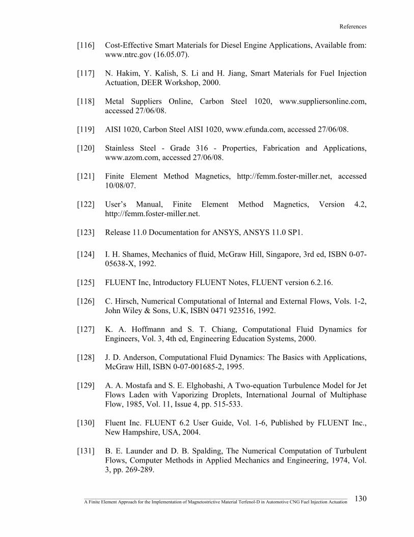
References
_______________________________________________________________________________________________________________ A Finite Element Approach for the Implementation of Magnetostrictive Material Terfenol-D in Automotive CNG Fuel Injection Actuation 130
[116] Cost-Effective Smart Materials for Diesel Engine Applications, Available from: www.ntrc.gov (16.05.07).
[117] N. Hakim, Y. Kalish, S. Li and H. Jiang, Smart Materials for Fuel Injection
Actuation, DEER Workshop, 2000. [118] Metal Suppliers Online, Carbon Steel 1020, www.suppliersonline.com,
accessed 27/06/08. [119] AISI 1020, Carbon Steel AISI 1020, www.efunda.com, accessed 27/06/08. [120] Stainless Steel - Grade 316 - Properties, Fabrication and Applications,
www.azom.com, accessed 27/06/08. [121] Finite Element Method Magnetics, http://femm.foster-miller.net, accessed
10/08/07. [122] User’s Manual, Finite Element Method Magnetics, Version 4.2,
http://femm.foster-miller.net. [123] Release 11.0 Documentation for ANSYS, ANSYS 11.0 SP1. [124] I. H. Shames, Mechanics of fluid, McGraw Hill, Singapore, 3rd ed, ISBN 0-07-
05638-X, 1992. [125] FLUENT Inc, Introductory FLUENT Notes, FLUENT version 6.2.16. [126] C. Hirsch, Numerical Computational of Internal and External Flows, Vols. 1-2,
John Wiley & Sons, U.K, ISBN 0471 923516, 1992. [127] K. A. Hoffmann and S. T. Chiang, Computational Fluid Dynamics for
Engineers, Vol. 3, 4th ed, Engineering Education Systems, 2000. [128] J. D. Anderson, Computational Fluid Dynamics: The Basics with Applications,
McGraw Hill, ISBN 0-07-001685-2, 1995. [129] A. A. Mostafa and S. E. Elghobashi, A Two-equation Turbulence Model for Jet
Flows Laden with Vaporizing Droplets, International Journal of Multiphase Flow, 1985, Vol. 11, Issue 4, pp. 515-533.
[130] Fluent Inc. FLUENT 6.2 User Guide, Vol. 1-6, Published by FLUENT Inc.,
New Hampshire, USA, 2004. [131] B. E. Launder and D. B. Spalding, The Numerical Computation of Turbulent
Flows, Computer Methods in Applied Mechanics and Engineering, 1974, Vol. 3, pp. 269-289.

References
[132] T. H. Shih, W. W. Liou, A. Shabbir, Z. Yang and J. Zhu, A New k- ε Eddy Viscosity Model for High Reynolds Number Turbulent Flows, Computers & Fluids, 1995, Vol. 24, Issue 3, pp.227-238.
[133] D. C. Wilcox, Turbulence Modeling for CFD, 2nd Edition, DCW Industries,
ISBN 192872910X, 1994. [134] P. L. George, Automatic Mesh Generation and Finite Element Computation,
Handbook of Numerical Analysis, Elsevier, 1996. [135] M. C. Bastarrica and N. H. Kahler, Designing a Product Family of Meshing
Tools, Advances in Engineering Software, 2006, Vol. 37, Issue 1, pp. 1-10. [136] J. H. Ferziger and M. Peric, Computational Methods for Fluid Dynamics, 3rd
ed, Springer, New York, ISBN-3-540-42074-6, 2002. [137] Technical Notes, RC Fuel Injection, www.rceng.com, accessed 13/04/08.
_______________________________________________________________________________________________________________ A Finite Element Approach for the Implementation of Magnetostrictive Material Terfenol-D in Automotive CNG Fuel Injection Actuation 131

APPENDICES

APPENDIX A
PUBLICATIONS

Appendices
This work has been disseminated through the following publications. Journal Papers:
H. A. Chowdhury, S. A. Mazlan and A. G. Olabi, Implementation of Magnetostrictive Material Terfenol-D in CNG Fuel Injection Actuation, Advanced Materials Research, Vols. 47-50, 2008, pp. 630-633.
H. A. Chowdhury, S. A. Mazlan and A. G. Olabi, A Simulation Study of Magnetostrictive Material Terfenol-D in Automotive CNG Fuel Injection Actuation, Solid State Phenomenon. (under review)
H. A. Chowdhury, S. A. Mazlan and A. G. Olabi, A Comparative Magnetic Simulation Study between ANSYS and FEMM for the Implementation of Magnetostrictive Material Terfenol-D in CNG Fuel Injection Actuation, Journal of Magnetism and Magnetic Materials. (under review)
Conferences:
H. A. Chowdhury and A. G. Olabi, A Finite Element Approach for the Implementation of Magnetostrictive Material Terfenol-D in CNG Fuel Injection Actuation, presented at the ASME 2008 International Design Engineering Technical Conferences & Computers and Information in Engineering Conference IDETC/CIE 2008, Brooklyn, New York, USA, August 3-6, 2008.
H. A. Chowdhury, S. A. Mazlan and A. G. Olabi, Implementation of Magnetostrictive Material Terfenol-D in CNG Fuel Injection Actuation, presented at the International Conference on Multifunctional Materials and Structures, Hong Kong, China, 28-31 July, 2008.
H. A. Chowdhury, S. A. Mazlan and A. G. Olabi, A Comparative Magnetic Simulation Study between ANSYS and FEMM for the Implementation of Magnetostrictive Material Terfenol-D in CNG Fuel Injection Actuation, presented at the Joint European Magnetic Symposia, Dublin, Ireland, September 14-19, 2008.
H. A. Chowdhury, S. A. Mazlan and A. G. Olabi, A Simulation Study of Magnetostrictive Material Terfenol-D in Automotive CNG Fuel Injection Actuation, presented at the 2008 European Materials Research Society (E-MRS) Fall Meeting, Warsaw, Poland, September 15-19, 2008.
H. A. Chowdhury and A. G. Olabi, Recent CNG Developments and Its Implications For Heavy-Duty Vehicles, in Proceedings of The International Conference on Vehicles Alternative Fuel Systems & Environmental Protection, 2006, pp. 75-89.
_______________________________________________________________________________________________________________ A Finite Element Approach for the Implementation of Magnetostrictive Material Terfenol-D in Automotive CNG Fuel Injection Actuation
I

APPENDIX B
CAD DRAWINGS
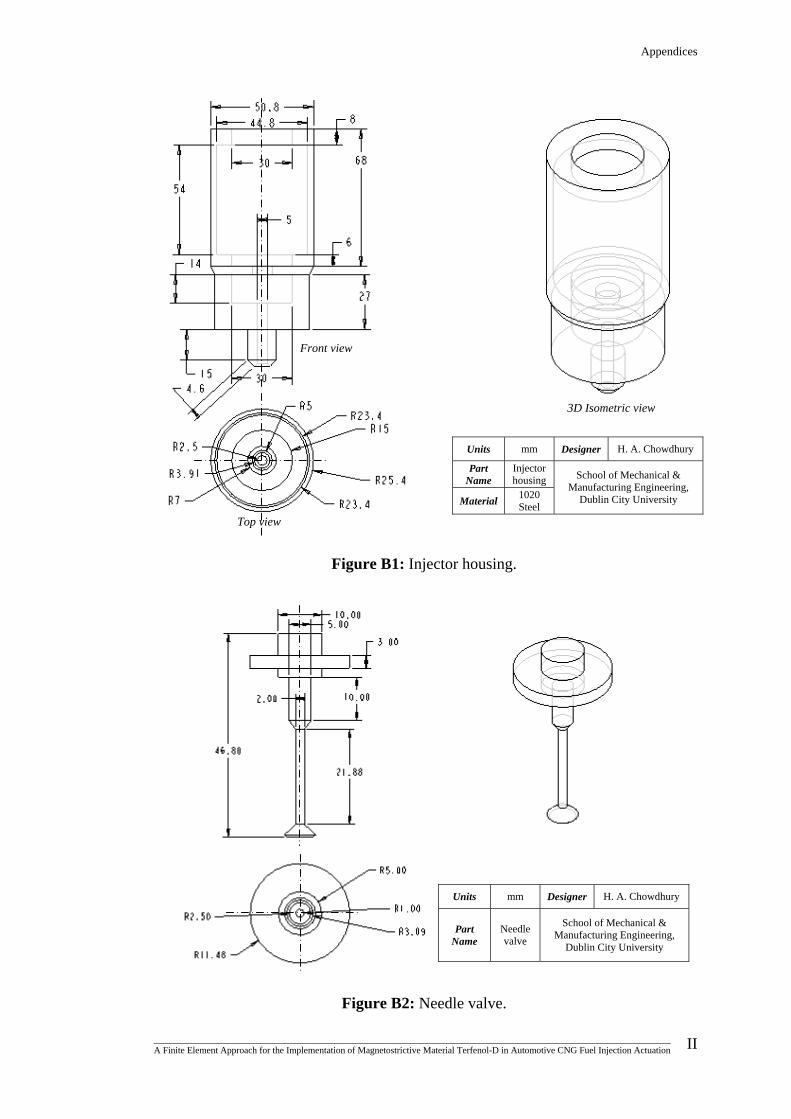
Appendices
Figure B1: Injector housing.
Front view
Figure B2: Needle valve.
Units mm Designer H. A. Chowdhury
Part Name
Injector housing
Material 1020 Steel
School of Mechanical & Manufacturing Engineering,
Dublin City University
3D Isometric view
Top view
Units Designer mm H. A. Chowdhury
School of Mechanical & Manufacturing Engineering, Part
Name Needle valve Dublin City University
_______________________________________________________________________________________________________________ A Finite Element Approach for the Implementation of Magnetostrictive Material Terfenol-D in Automotive CNG Fuel Injection Actuation
II

Appendices
Units Designer mm H. A. Chowdhury
Part Name Plunger School of Mechanical &
Manufacturing Engineering, 316 Stainless
steel Dublin City University Material
Figure B3: Plunger
Figure B4: Closing spring.
Units mm Designer H. A. Chowdhury
Part Name
Closing spring
School of Mechanical & Manufacturing Engineering,
Dublin City University
Pitch = 1.45 mm
Dia = 0.75 mm 16
16
_______________________________________________________________________________________________________________ A Finite Element Approach for the Implementation of Magnetostrictive Material Terfenol-D in Automotive CNG Fuel Injection Actuation
III

APPENDIX C
FEMM MAGNETOSTATIC
SIMULATION RESULTS
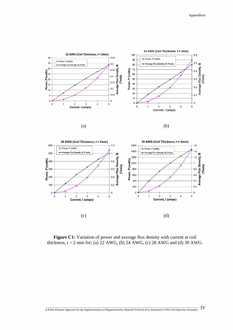
Appendices
(a)
(b)
(c)
(d)
Figure C1: Variation of power and average flux density with current at coil
thickness, t = 2 mm for; (a) 22 AWG, (b) 24 AWG, (c) 28 AWG and (d) 30 AWG.
_______________________________________________________________________________________________________________ A Finite Element Approach for the Implementation of Magnetostrictive Material Terfenol-D in Automotive CNG Fuel Injection Actuation
IV
Appendices
(a)
(b)
(c)
(d)
Figure C2: Variation of power and average flux density with current at coil
thickness, t = 3 mm for; (a) 22 AWG, (b) 24 AWG, (c) 28 AWG and (d) 30 AWG.
_______________________________________________________________________________________________________________ A Finite Element Approach for the Implementation of Magnetostrictive Material Terfenol-D in Automotive CNG Fuel Injection Actuation
V

Appendices
(a)
(b)
(c)
(d)
Figure C3: Variation of power and average flux density with current at coil
thickness, t = 4 mm for; (a) 22 AWG, (b) 24 AWG, (c) 28 AWG and (d) 30 AWG.
_______________________________________________________________________________________________________________ A Finite Element Approach for the Implementation of Magnetostrictive Material Terfenol-D in Automotive CNG Fuel Injection Actuation
VI

Appendices
(a)
(b)
(c)
(d)
Figure C4: Variation of power and average flux density with current at coil
thickness, t = 5 mm for; (a) 22 AWG, (b) 24 AWG, (c) 28 AWG and (d) 30 AWG.
_______________________________________________________________________________________________________________ A Finite Element Approach for the Implementation of Magnetostrictive Material Terfenol-D in Automotive CNG Fuel Injection Actuation
VII


