A Case Study: Complex Accident Reconstruction from … Accident... · 3D ANIMATION • LASER...
16
3D ANIMATION • LASER SCANNING • CRIME, FIRE & ACCIDENT RECONSTRUCTION • FORENSIC VIDEO DOCUMENTATION • ANALYSIS • VISUALIZATION • OVER 1000 CASES • NEVER EXCLUDED • PLAINTIFF & DEFENSE 115 S. Church Street • Grass Valley, CA 95945 • (877) 339-7378 • [email protected] • precisionsim.com A Case Study: Complex Accident Reconstruction from Video Footage Document, Analyze, Visualize; Turn Jurors into Witnesses
Transcript of A Case Study: Complex Accident Reconstruction from … Accident... · 3D ANIMATION • LASER...

3D ANIMATION • LASER SCANNING • CRIME, FIRE & ACCIDENT RECONSTRUCTION • FORENSIC VIDEO DOCUMENTATION • ANALYSIS • VISUALIZATION • OVER 1000 CASES • NEVER EXCLUDED • PLAINTIFF & DEFENSE
115 S. Church Street • Grass Valley, CA 95945 • (877) 339-7378 • [email protected] • precisionsim.com
A Case Study:Complex Accident Reconstruction
from Video Footage
Document, Analyze, Visualize; Turn Jurors into Witnesses

A young woman runs across Market Street in San Francisco in an effort to catch a bus on the opposite side of the street. The street has many pedestrians crossing before she arrives but when she steps into the street she is alone. As she begins to cross in front of the stopped traffic at the intersection, a bus in the number 2 lane begins to move forward, striking her. The woman falls, and the bus rolls over both her legs, resulting in a double amputation. The event is captured on video cameras installed within the bus itself.
Complex Accident Reconstruction From Video Footage
The Scenario
The ChallengeAlthough the event is captured on video, a number of critical issues and questions remain unanswered.
What color are the signal crossing lights at critical times in the event? None of the five camera views depict the traffic signals themselves. What is the speed and position of the bus, and the pedestrian at each point throughout the event? The video generally depicts their relative locations, but not with enough fidelity to stand up as an accurate reconstruction of the event. Clearly the pedestrian could see the bus, only a few feet from her as she crossed, but could the bus driver see the pedestrian? And if so, when would she have become visible and recognizable as a hazard?
•
• • •
What is needed is a method to extract all the available data from the video footage and then use it to fill in the missing pieces. Then, if an accurate reconstruction can be completed, the results should be visualized from a perspective that allows the jury to see the actions and timings of both parties in conjunction with the signal timing.
115 S. Church Street • Grass Valley, CA 95945 • (877) 339-7378 • [email protected] • precisionsim.com
Document, Analyze, Visualize; Turn Jurors into Witnesses
Page 1PRECISIONSIM.com • 877.339.7378 • Turn Jurors into Witnesses© 2016 Precision Simulations Inc, All Rights Reserved
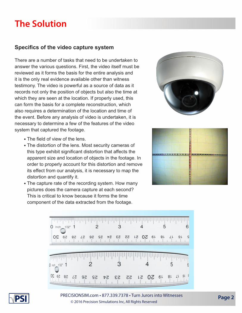
Specifics of the video capture system
There are a number of tasks that need to be undertaken to answer the various questions. First, the video itself must be reviewed as it forms the basis for the entire analysis and it is the only real evidence available other than witness testimony. The video is powerful as a source of data as it records not only the position of objects but also the time at which they are seen at the location. If properly used, this can form the basis for a complete reconstruction, which also requires a determination of the location and time of the event. Before any analysis of video is undertaken, it is necessary to determine a few of the features of the video system that captured the footage.
The field of view of the lens.The distortion of the lens. Most security cameras of this type exhibit significant distortion that affects the apparent size and location of objects in the footage. In order to properly account for this distortion and remove its effect from our analysis, it is necessary to map the distortion and quantify it.The capture rate of the recording system. How many pictures does the camera capture at each second? This is critical to know because it forms the time component of the data extracted from the footage.
••
•
The Solution
Page 2PRECISIONSIM.com • 877.339.7378 • Turn Jurors into Witnesses© 2016 Precision Simulations Inc, All Rights Reserved

These values can all be determined by interfacing directly with the camera system that recorded the footage. In this case, it means a site visit to inspect the bus and the cameras located onboard. The field of view of the lens and the mapping of its distortion are determined by use of a calibrated template that is recorded and analyzed in the computer. The capture rate of the camera’s recording system is determined by viewing a digital stopwatch through the camera and recording 10 or more seconds of video. When viewed later, the footage of the stopwatch directly illustrates how often the camera takes a picture. This rate is expressed in “frames per second”, or how many images are captured per second of time that passes. In the case of this system, the capture rate was determined to be 4 frames per second. This means that there are four discrete locations of the objects seen in the footage for every second of time that passes. Conversely, motion that occurs between consecutive frames occur ¼ of a second apart.
3D Laser Scanning of Accident Scene
At PSI, our method in analyzing these types of cases starts with creating the 3D Working Model. By combining an accurate 3D model of the environment, vehicles and actors with the available physical evidence, PSI uses the precision of the computer to virtually reconstruct the events.
In order to preserve the accident scene, PSI used its 3D laser scanning system, taking over 15,000,000 measurements of the scene and preserving it in exact detail for later use in the computer based reconstruction. This form of documentation allows PSI and other experts to revisit the scene at any time, removing the challenges of performing all the analysis on site. Any changes to the accident scene that occur after the laser scan do not affect one’s ability to see the accident scene as it was at the time of the event. As will be shown shortly, having a perfect 3D model of the scene and the criti-cal objects always provides “downstream” benefits.
San Francisco Accident Scene Laser Scan
Page 3PRECISIONSIM.com • 877.339.7378 • Turn Jurors into Witnesses© 2016 Precision Simulations Inc, All Rights Reserved

3D Laser Scanning of Bus
Laser Scanning the bus serves dual purposes: first, it provides the most accurate 3D model data for the bus, thereby ensuring that reconstruction in the computer maintains fidelity to the real world dimensions and details of the bus. Second, it allows the review of potential issues related to items in the bus interior, for instance, obstructions to the driver’s line of sight.
San Francisco Bus Laser Scan Exterior
San Francisco Bus Laser Scan Interior San Francisco Bus Laser Scan Interior - Driver’s Seat
Determination of Signal Timing
The video evidence provides clues to the motion and relative positions and speeds of the bus and the pedestrian. A casual review of the footage shows that the bus is in motion at the time of impact and that the pedestrian entered the street outside the crosswalk. However, what is not directly seen in the video and is of critical importance is “Who had the right of way? Which one had a green light/which one had a red light?”
Page 4PRECISIONSIM.com • 877.339.7378 • Turn Jurors into Witnesses© 2016 Precision Simulations Inc, All Rights Reserved

Bus Slowing - Pedestrians Waiting to Cross
The video footage does reveal clues to this question. The beginning of the video shows the bus approaching the intersection and slowing to a stop next to an already stopped Lexus, presumably due to the traffic signal displaying red for the bus. As the bus is slowing to a stop, two pedestrians can be seen standing on the right-side sidewalk. As the frames click by, the pedestrians remain on the sidewalk, waiting for the signal light to change and indicate it is safe to cross. At about the same time the bus comes to a stop, the frames show the pedestrians beginning to swing their legs and arms forward as they begin to take a first step into the street. If we make the assumption that the two pedestrians begin to cross in response to the change in the traffic signal to a “go” (this is an icon of a white walking man for the pedestrian signal), then we can say that the pedestrian crossing signal changed from red/stop to white/go prior to the frame showing the pedestriansinitial movement. Bringing in opinion from a human factors expert provides a time between the signal change and the first frame of obvious motion for the waiting pedestrians – the defense expert opined that this time would likely be 1.5 seconds. Therefore, we know that the pedestrian signal changed to go/white 1.5 seconds prior to the first frame of obvious move- ment on the part of the waiting pedestrians. This data provides a synchronization point between the time code on the video footage and the overall signal timing that controls the intersection.
Bus Stopped - Pedestrians Begin to Cross
Bus Stopped - Pedestrians Continue to Cross
Page 5PRECISIONSIM.com • 877.339.7378 • Turn Jurors into Witnesses© 2016 Precision Simulations Inc, All Rights Reserved

A review of the signal timing card reveals the entire traffic light sequence and an important new fact: The bus had a green light at impact, the pedestrian signal was displaying a red hand. Further review shows that there was a 3 second “all red” phase and that the light for the bus had been green for 1.5 seconds before the pedestrian entered the roadway and 4 seconds by the time of impact. Conversely, the pedestrian had a flashing red light for 10 seconds and a solid red hand for 4.5 seconds before she entered the roadway and a solid red light for 7 seconds by the time of impact. We can now add this newly derived data to the 3D Working Model and see how it coincides with the timing and motion of the bus and pedestrians.
Page 6PRECISIONSIM.com • 877.339.7378 • Turn Jurors into Witnesses© 2016 Precision Simulations Inc, All Rights Reserved

Life-Sized Intersection Diagram
Remember the mention about laser scanning providing downstream benefits? Here’s one of them. In order to use the video to determine the specific motions and timings of the bus and the pedestrian, a method was devised to replicate what is seen on the footage, during an off-site motion study. The idea is straightforward: recreate the accident scene off-site, (reconstructing the accident in the middle of one of the busiest intersections in San Francisco was not an option), and move the bus and pedestrian towards one another in a way that aligns with what is seen in the video footage. PSI contracted with a billboard printing company to produce at 55 ft. x 35 ft. heavy-duty canvas print that was accurate and with sufficient resolution to pick out the details seen as the roadway passes by the video camera. Now, the experts are free to reconstruct the accident in a location of their choice that allows sufficient time to complete the analysis, without concerns such as traffic control.
CAD Drawing; Life-sized Diagram of Intersection - 55 Feet Wide X 35 Feet Tall
Life-sized Diagram During Reconstruction
Page 7PRECISIONSIM.com • 877.339.7378 • Turn Jurors into Witnesses© 2016 Precision Simulations Inc, All Rights Reserved

Off-Site Video Reconstruction
Once the site was selected to perform the video alignment study with the life-sized print; the bus, the print, and an exemplar pedestrian are brought together to synchronize their motion to match the video.
The general idea is to look through the same camera that recorded the event footage and align the bus, pedestrian, and intersection diagram at each frame to match what is seen in the footage. If we can move the bus and pedestrian so that they line up in the study with their positions in the footage, we can document the relative locations and develop a time/position reconstruction frame by frame.
Actual Footage of Incident Off-site Reconstruction
Actual Footage of Incident Off-site Reconstruction
Actual Footage of Incident Off-site Reconstruction
Page 8PRECISIONSIM.com • 877.339.7378 • Turn Jurors into Witnesses© 2016 Precision Simulations Inc, All Rights Reserved

Due to the clear and large degree of distortion in the camera that captured the event footage, it is imperative that we use the same camera when we view the positions during the study. If we attempt to perform the study with another camera, such as one of our hi-definition cameras, then the distortion will not be accounted for and the derived locations will be in error. The error is larger at the edges of the camera frame and decrease as we move towards the center, further complicating any post-study effort to reverse the problem. This issue will be discussed again later when we review the plaintiff’s work.
The result of performing this exercise in a frame by frame manner is a demonstrably accurate 3D accident reconstruction of the event and the relative motions of each object leading up to and through impact. The location of the bus, the pedestrian and the timing of the traffic signals is now known to a high degree of accuracy for every frame of video. With a complete reconstruction in hand, the experts can now turn to analyzing the data within the context of other critical issues.
CAD Drawing Showing Known Locations
Page 9PRECISIONSIM.com • 877.339.7378 • Turn Jurors into Witnesses© 2016 Precision Simulations Inc, All Rights Reserved

Sight Cone Top Down View
Line of Sight Obstruction Areas
Given the size and close proximity of the bus, (40 feet long, 8 feet wide, 8.5 feet high, the first vehicle in line and approximately 10 feet away when the pedestrian entered the street) it is certain that the bus was available to be seen by the pedestrian. However, the bus driver’s view towards the unexpected late crossing pedestrian is not as certain. The bus itself blocks the driver’s sight to portions of the roadway around the bus. The combination of these obstructions and the pedestrian’s 4’11” height may limit her visibility to the driver.
Using the previously captured laser scan data, PSI created a 3D Working Model of the bus interior and driver’s eye position in order to analyze the issue. Performing this task in the computer via the 3D working model has two distinct benefits: the precision and adjustability afforded by the computer and the ability to analyze it in context of the environment, derived motions and physical evidence of the virtual accident scene. Visualizing the results in connection with the accident reconstruction and signal timing elements allows a more detailed picture of the dynamic issues at play during the event.
By modeling the bus interior and the driver’s eye position, the 3D Working Model creates visible geometry around the bus indicating which areas are not visible to the bus driver. By attaching this visible geometry to the 3D model of the bus as it moves, we can see the interplay between the line of sight obstructions and the position of the pedestrian as she crosses in front of the bus.
Site Cone Example
Site Cone - Perspective View
Page 10PRECISIONSIM.com • 877.339.7378 • Turn Jurors into Witnesses© 2016 Precision Simulations Inc, All Rights Reserved

Photos for 3D Animation Backgrounds
With the direct analysis completed, the final step towards producing a realistic and accurate 3D animation of the event is to capture high resolution photos to serve as the background for the animation. Using the 3D Working Model, the viewing locations for the animation are selected and photos are taken from the same vantage points in the real world scene. Using photos and the laser scan data allows PSI to accurately overlay the data against the most realistic back- ground. This reduces costs by precluding the need to create 3D models for the background and results in the most realistic animation due to the fidelity of the photo.
Frame from Final Animation
Page 11PRECISIONSIM.com • 877.339.7378 • Turn Jurors into Witnesses© 2016 Precision Simulations Inc, All Rights Reserved
Rebuttal of Opposition Expert’s False Camera Analysis and Reconstruction
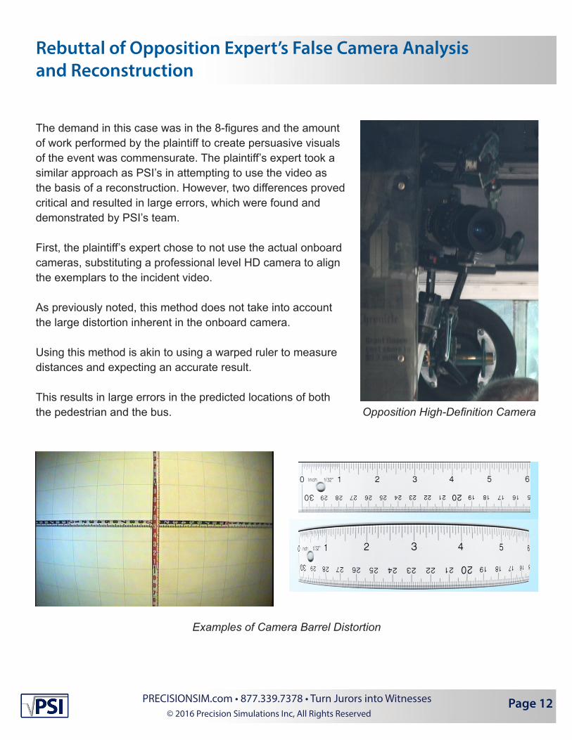
The demand in this case was in the 8-figures and the amount of work performed by the plaintiff to create persuasive visuals of the event was commensurate. The plaintiff’s expert took a similar approach as PSI’s in attempting to use the video as the basis of a reconstruction. However, two differences proved critical and resulted in large errors, which were found and demonstrated by PSI’s team.
First, the plaintiff’s expert chose to not use the actual onboard cameras, substituting a professional level HD camera to align the exemplars to the incident video. As previously noted, this method does not take into account the large distortion inherent in the onboard camera. Using this method is akin to using a warped ruler to measure distances and expecting an accurate result. This results in large errors in the predicted locations of both the pedestrian and the bus. Opposition High-Definition Camera
Examples of Camera Barrel Distortion
Page 12PRECISIONSIM.com • 877.339.7378 • Turn Jurors into Witnesses© 2016 Precision Simulations Inc, All Rights Reserved
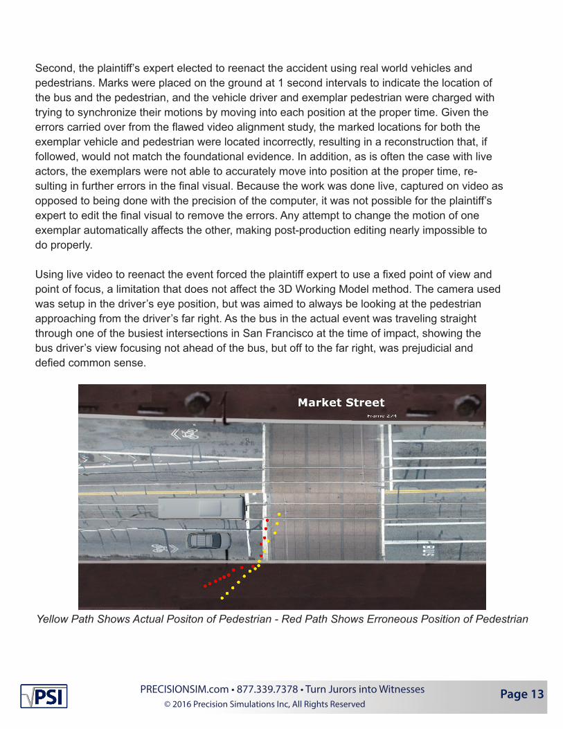
Second, the plaintiff’s expert elected to reenact the accident using real world vehicles and pedestrians. Marks were placed on the ground at 1 second intervals to indicate the location of the bus and the pedestrian, and the vehicle driver and exemplar pedestrian were charged with trying to synchronize their motions by moving into each position at the proper time. Given the errors carried over from the flawed video alignment study, the marked locations for both the exemplar vehicle and pedestrian were located incorrectly, resulting in a reconstruction that, if followed, would not match the foundational evidence. In addition, as is often the case with live actors, the exemplars were not able to accurately move into position at the proper time, re- sulting in further errors in the final visual. Because the work was done live, captured on video as opposed to being done with the precision of the computer, it was not possible for the plaintiff’s expert to edit the final visual to remove the errors. Any attempt to change the motion of one exemplar automatically affects the other, making post-production editing nearly impossible to do properly.
Using live video to reenact the event forced the plaintiff expert to use a fixed point of view and point of focus, a limitation that does not affect the 3D Working Model method. The camera used was setup in the driver’s eye position, but was aimed to always be looking at the pedestrian approaching from the driver’s far right. As the bus in the actual event was traveling straight through one of the busiest intersections in San Francisco at the time of impact, showing the bus driver’s view focusing not ahead of the bus, but off to the far right, was prejudicial and defied common sense.
Yellow Path Shows Actual Positon of Pedestrian - Red Path Shows Erroneous Position of Pedestrian
Page 13PRECISIONSIM.com • 877.339.7378 • Turn Jurors into Witnesses© 2016 Precision Simulations Inc, All Rights Reserved

Judges Ruling to Exclude Opposition Expert’s Work Product
As would be expected in a case of this magnitude, both sides filed motions to exclude the opposition’s visual reenactment of the accident. The defense motion focused on the flawed approach used by the plaintiff’s expert in aligning the location with a different camera than the one that captured the incident footage. Also highlighted in the defense motion was the prejudicial and nonsensical view used to illustrate the pedestrians approach - essentially suggesting to the jury that the proper method for driving this bus would be to drive through the intersection without looking where it was headed.
At trial, PSI’s CEO, Craig Fries was allowed to show over 100 slides describing the methods used to create the final 3D animations as well as the animations themselves from 3 different views. The plaintiff’s expert was precluded by the court from showing any of the visual reenactment video.
San Francisco Accident Scene Laser Scan
Page 14PRECISIONSIM.com • 877.339.7378 • Turn Jurors into Witnesses© 2016 Precision Simulations Inc, All Rights Reserved

3D ANIMATION • LASER SCANNING • CRIME, FIRE & ACCIDENT RECONSTRUCTION • FORENSIC VIDEO DOCUMENTATION • ANALYSIS • VISUALIZATION • OVER 1000 CASES • NEVER EXCLUDED • PLAINTIFF & DEFENSE