
A-777 A-676 Fran~ais - · PDF fileINSTALLATION POWER-CORD CAUTION Handle the power cord by the...
15
CD PIONEER: The Art of Entertainment Operating Instructions Mode d'emploi Bedrenungsanreftung Istruzioni per I'uso Gebruiksaanwijzing Bruksanvisning Manual de instrucciones Manual de instru~{jes Portugues Espanol Svenska Nederlands Italiano Deutsch Fran~ais English ·-0 WARNING: TO PREVENT FIRE OR SHOCK HAZARD. DO NOT EXPOSE THIS APPLIANCE TO RAIN OR MOISTURE. ~- co '~.:o<· 0 ~ .-. ':::'-00 .-.- t.~~_:~r ",. ,-:. eo-":_ .. _.";,,, .":' .. I .. -~·- '; ~ : : ~-;--=-- O Q. Q. O· ClCJCJ CJ 0 ...... _. ;_"'-._ ~......,: _." ·L"""""'''._~'·'a_~ ...-.,. o Illustration shows model A· 777. L'illustration represente Ie modele A· 777. Die Abbildung zeigt das Modell A- 777. L'illustrazione mostra il modello A-777. Op de illustratie staat model A-777. Bilden visar modell A- 777. La ilustraci6n muestra el modele A· 777. A ilustrac;:ao mostra 0 modele A· 777. ltJJlID1DD .-._ - ••• A - 777 A-777 A-676 STEREO AMPLIFIER AMPLIFICA TEUR STEREO STEREOVERSTARKER AMPLIFICA TORE STEREO STEREO-VERSTERKER STEREOFORSTARKARE AMPLIFICADOR ESTEREOFONICO AMPLIFICADOR ESTEREO • IMPORTANT A The lightning flash with arrowhead, within an equilateral triangle, is intended to alert the user to the presence of un insulated "dangerous voltage" within the product's enclosure that may be of sufficient magnitude to constitute a risk of electric shock to persons. CAUTION: TO PREVENT THE RISK OF ELECTRIC SHOCK. DO NOT REMOVE COVER lOR BACK). NO USER- SERVICEABLE PARTS INSIDE. REFER SERVICING TO QUALIFIED SERVICE PERSONNEL. The exclamation point within an eqUilateral triangle is intended to alert the user to the presence of important operating and maintenance (servicing) instructions in the literature accompanying the appliance.
Transcript of A-777 A-676 Fran~ais - · PDF fileINSTALLATION POWER-CORD CAUTION Handle the power cord by the...
CD PIONEER:The Art of Entertainment
Operating InstructionsMode d'emploi
BedrenungsanreftungIstruzioni per I'uso
GebruiksaanwijzingBruksanvisning
Manual de instruccionesManual de instru~{jes
Portugues
Espanol
Svenska
Nederlands
Italiano
Deutsch
Fran~ais
English
·-0
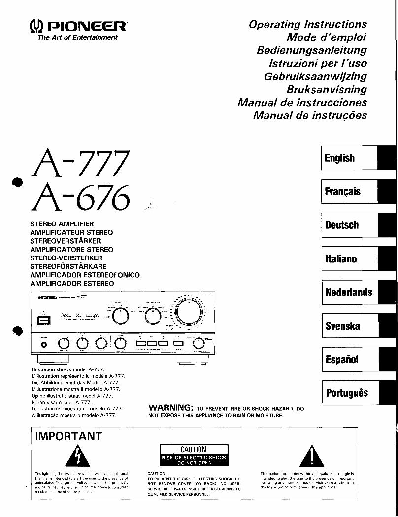
WARNING: TO PREVENT FIRE OR SHOCK HAZARD. DONOT EXPOSE THIS APPLIANCE TO RAIN OR MOISTURE.
~- co
'~.:o<· 0 ~ .-. ':::'-00.-.-
t.~~_:~r ",. ,-:.
eo-":_ .. _.";,,, .":' .. I .. -~·- '; ~ : : ~-;--=--O Q.Q. O· ClCJCJ CJ 0......_. ;_"'-._ ~......,: _." ·L"""""'''._~'·'a_~ ...-.,.
o
Illustration shows model A· 777.
L'illustration represente Ie modele A· 777.
Die Abbildung zeigt das Modell A- 777.L'illustrazione mostra il modello A-777.
Op de illustratie staat model A-777.Bilden visar modell A- 777.La ilustraci6n muestra el modele A· 777.
A ilustrac;:ao mostra 0 modele A· 777.
ltJJlID1DD .-._ - ••• A - 777
A-777A-676STEREO AMPLIFIER
AMPLIFICA TEUR STEREOSTEREOVERSTARKERAMPLIFICA TORE STEREOSTEREO-VERSTERKERSTEREOFORSTARKARE
AMPLIFICADOR ESTEREOFONICOAMPLIFICADOR ESTEREO
•
IMPORTANT
AThe lightning flash with arrowhead, within an equilateraltriangle, is intended to alert the user to the presence ofun insulated "dangerous voltage" within the product'senclosure that may be of sufficient magnitude to constitutea risk of electric shock to persons.
CAUTION:
TO PREVENT THE RISK OF ELECTRIC SHOCK. DO
NOT REMOVE COVER lOR BACK). NO USER
SERVICEABLE PARTS INSIDE. REFER SERVICING TO
QUALIFIED SERVICE PERSONNEL.
The exclamation point within an eqUilateral triangle isintended to alert the user to the presence of importantoperating and maintenance (servicing) instructions inthe literature accompanying the appliance.
"This product complies with the Radio Interference requirements of the EC (European Community) Directive 871308/EEC. "
Thank you for buying this PIONEER product.Please read through these operating instructions so you will know howto operate your model properly. After you have finished reading theinstructions, put them away in a safe place for future reference.In some countries or regions, the shape of the power plug and poweroutlet may sometimes differ from that shown in the explanatorydrawings. However, the method of connecting and operating the unitis the same.
I CONTENTS
FEATURES 2INSTALLATION 4CONNECTIONS 6PANEL FACiLITIES ; 10OPERATIONS o>/~ 20TROUBLESHOOTING 24SPECiFiCATIONS 28
] FEATURES
• Drive capacity 150 W + 150 W/4 0 (DIN). 100 W + 100 W/S 0(DIN) matching to high power and low impedance type speakersystem.[Model A-676 ..... 120 W + 120 W/40 (DIN). SO W + SO W/SO(DIN)]
• The use of Super Linear Circuit ensures high fidelity playback ofconsistent frequency characteristics, accompanied by maximumclarity.
• The use of a DIRECT circuit ensures high fidelity playback ofconsistent frequency characteristics, accompanied by maximumclarity.
• Clean ground technology prevents noise on power line from flowingto the signal ground line, permitting clean sound reproduction.
• Uses Channel Separation Enhancer Circuit to improve the stereosound field and sound quality.
• REC selector switch makes tape editing very simple.• Comes with a built-in phono equalizer which accepts MC cartridge.• Casted Power Transformer (A-777 only)• Honeycomb Frame Chassis• Honeycomb Heat Sink• Uses a complementary capacitor pair.
2<ARE1194>
En/Fr
"Cet article est con forme aux prescriptions de la directive communautaire de /a CE nr. 87/308/EEC (arrete du 16/8/89)."
Nous vous remercions pour cet achat d'un produit Pioneer.Nous vous demandons de lire soigneusement ce mode d'emploi; vousserez ainsi a meme de faire fonctionner I'appareil correctement. Apresavoir bien lu Ie mode d'emploi, Ie ranger dans un endroit sur pour pouvoirs'y referer ulterieurement.Dans certains pays ou certaines regions, la forme de la fiched' alimentation et de la prise d' alimentation peut differer de celie qui figuresur les schemas, mais les branchements et Ie fonctionnement de
I'appareil restent les memes.
TABLE DES MA TIERES
CARACTERISTIQUES 2INSTALLATION 4CONNEXIONS 6ELEMENTS DES PANNEAUX 10UTILISATION 20GUIDE DE DEPANNAGE 25FICHE TECHNIQUE 29
CARACTERISTIQUES
• Capacite d' entralnement de 150 W + 150 W /4 0 (DIN), 100 W +100 W/S 0 pour I'utilisation de systemes d'enceintes de typepuissance elevee et basse impedance.[modele A-676 120 W + 120 W/4 0 (DIN), SO W + SO W/sn (DIN).]
• L'utilisation d'un circuit Super Lineaire garantit une reproduction hautefidelite de caracteristiques de frequences constantes, accompagnee
d'une c1arte maximum. f\• L'utilisation d'un circuit DIRECT garantit une reproduction haute
fidelite de caracteristiques de frequences constantes, avec une c1artemaximum.
• Technologie de terre propre empechant que les parasites de la ligned'alimentation passent dans la Iigne de terre du signal, permettantune excellente reproduction sonore.
• Utilise Ie circuit pour accroissement de la separation de chaines pourameliorer Ie champ acoustique stereo et la qualite de son.
• Le selecteur d'enregistrement (REC) rend tres simple I'edition d'unebande.
• Equipe d' un correcteur pour entree phono acceptant des cellules abobine mobile (MC).
• Transformateur d'alimentation blinde (A-777 seulement)
• Chassis de type nid d'abeille• Radiateur thermique de type nid d'abeille• Utilise une paire de condensateurs complementaires.
INSTALLATION
POWER-CORD CAUTION
Handle the power cord by the plug. Do not pull out the plug by tuggingthe cord and never touch the power cord when your hands are wet asthis could cause a short circuit or electric shock. Do not place the unit,a piece of furniture, etc., on the power cord, or pinch the cord. Nevermake a knot in the cord or tie it with other cords. The power cordsshould be routed such that they are not likely to be stepped on. Adamaged power cord can cause fire or give you an electrical shock.Check the power cord once in a while. When you find it damaged, askyour nearest PIONEER authorized service center or your dealer for areplacement.
I LOCATION
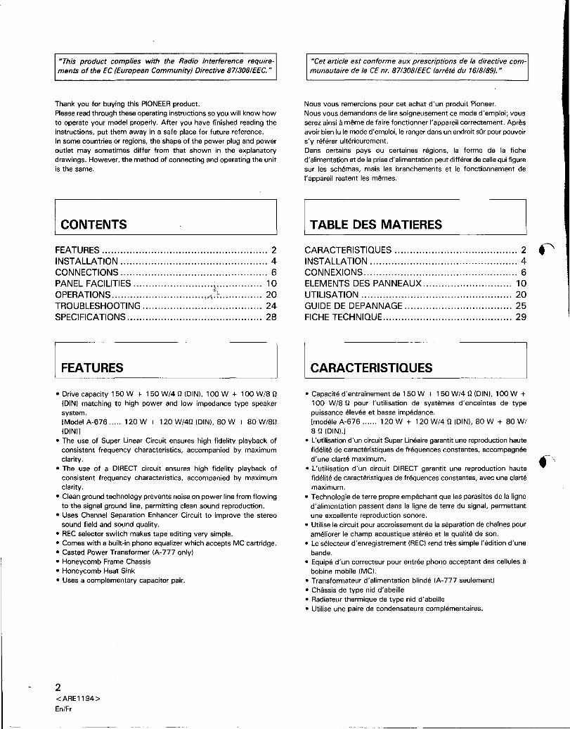
Install the amplifier in a well-ventilated location where it
will not be exposed to high temperature or humidity.Do not install the amplifier in a location which is exposed to direct
sunlight, or near to hot appliances or radiators. Excessive heat canadversely affect the cabinet and internal components. Installation ofthe amplifier in a damp or dusty environment may result in malfunction
or accident. (Also avoid installation near cookers ~tc., where theamplifier may be exposed to smoke, oil, steam orll~3t.)
A-777 onlyBe sure to place the unit on a level surface so that it stands firmlyon all its feet. If wobbly, adjust by attaching the supplied cushionspacers to one or more feet.
~Foot~C",hlo"""e,,¥ p", offpro"e"v' ,,"'.
MAINTENANCE OF EXTERNAL SURFACES
• Use a polishing cloth or dry cloth to wipe off dust and dirt.• When the surfaces are very dirty, wipe with a soft cloth dipped
in some neutral cleanser diluted five or six times with water, and
wrung out well, and then wipe again with a dry cloth. Do not usefurniture wax or cleaners.
• Never use thinners, benzine, insecticide sprays or other chemicalson or near this unit, since these will corrode the surfaces.
4<ARE1194>En/Fr
INSTALLATION
NOTE IMPORTANTE SUR LE CABLE D'ALIMENTATION
Tenir Ie cable d' alimentation par la fiche. Ne pas debrancher la prise entirant sur Ie cable et ne pas toucher Ie cable avec les mains mouillees.Cela risque de provoquer un court-circuit ou un choc electrique. Ne pasposer I'appareil ou un meuble sur Ie cable. Ne pas pincer Ie cable. Nepas faire de noeud avec Ie cable ou I'attacher a d'autres cables. Lescables d'alimentation doivent etre poses de fac;:ona ne pas etre ecrases.
Un cable abime peut provoquer un risque d'incendie ou un chocelectrique. Verifier Ie cable d'alimentation de temps en temps. ContacterIe service apres-vente PIONEERIe plus proche ou Ie revendeur pour unremplacement.
I EMPLACEMENT
Installer I' amplificateur dans un endroit bien aere ou il nesera pas expose it une temperature ou humidite elevee.Ne pas installer I'amplificateur dans un endroit qui est expose aux rayonsdirects du soleil, ni pres d' appareils chauds ou de radiateurs. Une chaleurexcessive peut affecter Ie coffret et les composants internes.L'installation de I'amplificateur dans un environnement humide oupoussiereux peut provoquer un fonctionnement defectueux ou unaccident. (Eviter egalement une installation pres de cuisinieres, etc. ouI'amplificateur peut etre expose a des fumees graisseuses, de la vapeurou a la chaleur).
A-777 seulement
Placez toujours I'unite sur une surface a niveau de sorte qu'ellerepose solidement sur tous ses pieds. Si elle est instable, ajustezen fixant les pieces d'ecartement amortissantes fournies sur un ouplusieurs pieds.
~Pied~PI'e,d''e,",m,"' ~ E"',v"," "pi" d, pro"e"'"amortlssante.
ENTRETIEN DES SURFACES EXTERIEURES
• Se servir d'un linge a polir or d'un chiffon see pour enlever lapoussiere ou les souillures.
• Si les surfaces sont tres sales, les frotter avec un linge doux trempedans un detergent neutre, dilue dans cinq or six fois son volumed'eau et bien essore, puis essuyer de nouveau avec un linge sec.Ne pas utiliser de cire ou de produit pour meubles .
• Ne jamais utiliser de diluant pour peinture, de benzine oud'insecticide en atomiseur sur ou a proximite de I'appareil, car sessurfaces en seraient endommagees.
~I
(
CONNECTIONS CONNEXIONS
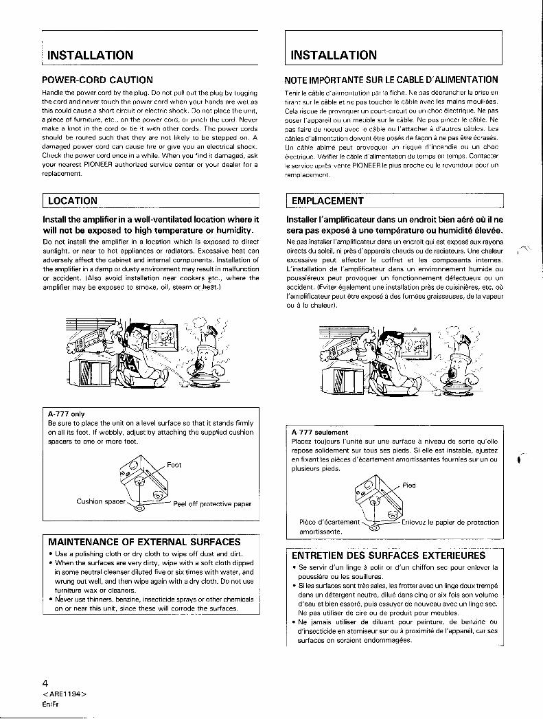
Illustration shows model A- 777.
CD player/ Lecteur CD
L'i1lustration represente Ie modele A-777.~----------Cassette deck/Platine cassette-------~ = <0
~ S".k."ys<.m B IRI(!)REC PLAY Systeme d'enceintes B •
ft L ~ droit (R)
Speaker system B (L)Systeme d'enceintes B
gauche (L) "'"
Speaker system A (L)Systeme d'enceintes Agauche (L)
Speaker system A (R)Systeme d' enceintes Adroit (R)
LD player, VCR etc./Lecteur LD, magnetoscope a cassette, etc.
Turntable/Table de lecture
PRECAUTION:
Ne pas inserer les barres de courtcircuit dans d'autres prises apres lesavoir retirees. Les conserver en lieusur.
CAUTION:
Do not insert the shorting bars intoother jacks, if not used. Keep them ina safe place.
Shorting bars (A-777 only):Barres de court-circuit (A-777 seulement):
Tuner/Syntoniseur
6<ARE1194>
En/Fr
CONNECTIONS
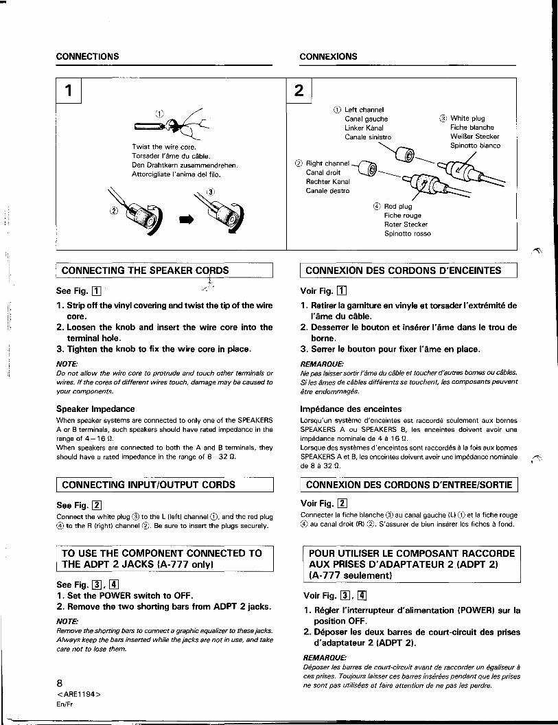
(~Twist the wire core.Torsader I'ame du cable.Den Drahtkern zusammendrehen.
Attorcigliate I'anima del filo.
I CONNECTING THE SPEAKER CO,RDSL
~;
See Fig. [!]1. Strip off the vinyl covering and twist the tip of the wire
core.
2. Loosen the knob and insert the wire core into the
terminal hole.
3. Tighten the knob to fix the wire core in place.
NOTE:
Do not allow the wire core to protrude and touch other terminals orwires. If the cores of different wires touch, damage may be caused toyour components.
Speaker ImpedanceWhen speaker systems are connected to only one of the SPEAKERSA or B terminals, such speakers should have rated impedance in the
range of 4-16 n.When speakers are connected to both the A and B terminals, theyshould have a rated impedance in the range of 8-32 n.
I CONNECTING INPUT/OUTPUT CORDS
See Fig.11JConnect the white plug @ to the L (left) channel CD, and the red plug
@) to the R (right) channel 0. Be sure to insert the plugs securely.
TO USE THE COMPONENT CONNECTED TO
THE ADPT 2 JACKS (A-777 only)
See Fig. rn, [!]1. Set the POWER switch to OFF.
2. Remove the two shorting bars from ADPT 2 jacks.
NOTE:
Remove the shorting bars to connect a graphic equalizer to these jacks.Always keep the bars inserted while the jacks are not in use, and takecare not to lose them.
8<ARE1194>
EnlFr
CONNEXIONS
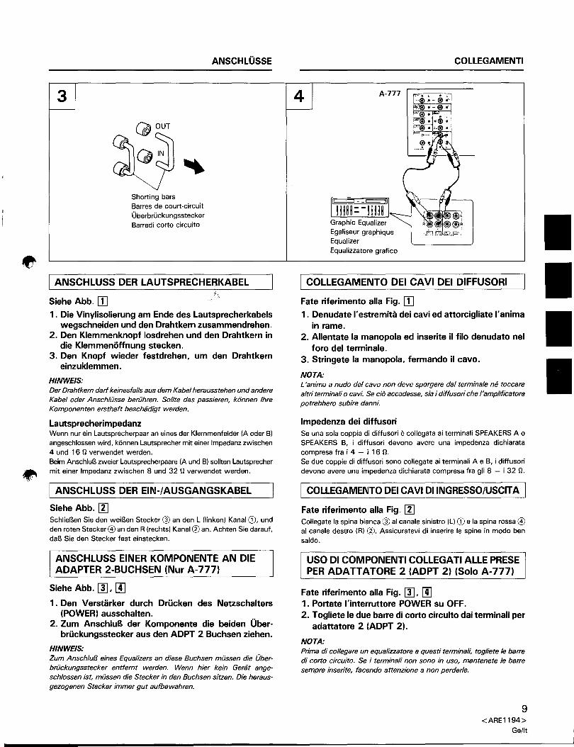
CD Left channel
Canal gauche @ White plugLinker Kanal Fiche blancheCanale sinistro WeiBer Stecker
(j) Rig'" oh'''''--/6iI ~ ~SPinotto biancoCanal droit "-y .. 4i!
Rechter Kanal ~ ~Canale destro ~@) Red plug
Fiche rougeRoter Stecker
Spinotto rosso
I CONNEXION DES CORDONS D'ENCEINTES
Voir Fig. [!]1. Retirer la garniture en vinyle et torsader I'extremite de
I'ame du cable.
2. Desserrer Ie bouton et inserer I'ame dans Ie trou deborne.
3. Serrer Ie bouton pour fixer I'ame en place.
REMARQUE:
Ne pas laisser sortir rame du cable et toucher d'autres bomes ou cables.Si les ames de cables differents se touchent, les composants peuvent
etre endommages.
Impedance des enceintesLorsqu'un systeme d'enceintes est raccorde seulement aux bornesSPEAKERS A ou SPEAKERS B, les enceintes doivent avoir une
impedance nominale de 4 a 16 n.Lorsque des systemes d'enceintes sont raccordes a la fois aux bornes
SPEAKERS A et B, les enceintes doivent avoir une impedance nominale I~de 8 a 32 n.
[ CONNEXION DES CORDONS D'ENTREE/SORTIE I
Voir Fig. I1JConnecter la fiche blanche @ au canal gauche (Ll CD et la fiche rouge@) au canal droit (R) 0. S'assurer de bien inserer les fiches a fond.
POUR UTILISER LE COMPOSANT RACCORDEAUX PRISES D' ADAPT A TEUR 2 (ADPT 2)(A-777 seulement)
Voir Fig. rn, [!]1. Regier l'interrupteur d'alimentation (POWER) sur la
position OFF.
2. Deposer les deux barres de court-circuit des prisesd'adaptateur 2 (ADPT 2).
REMARQUE:
Deposer les barres de court-circuit avant de raccorder un egaliseur aces prises. Toujours laisser ces barres inserees pendant que les prisesne sont pas utilisees et faire attention de ne pas les perdre.
ANSCHLOSSE
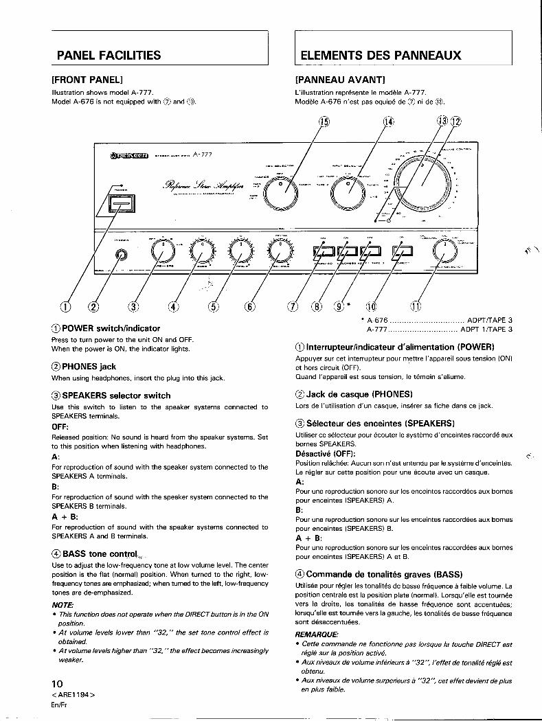
Shorting barsBarres de court-circuit
OberbruckungssteckerBarredi corto circuito
I ANSCHLUSS DER LAUTSPRECHERKABEL"
Siehe Abb. [I] .1. Die Vinylisolierung am Ende des Lautsprecherkabels
wegschneiden und den Drahtkern zusammendrehen.2. Den Klemmenknopf losdrehen und den Drahtkern in
die Klemmenoffnung stecken.3. Den Knopf wieder festdrehen. um den Drahtkern
einzuklemmen.
HINWEIS:Der Drahtkern dart keinesfal/s aus dem Kabel herausstehen und andere
Kabel oder AnschlUsse beriihren. Sol/te das passieren, k6nnen IhreKomponenten ersthaft beschadigt werden.
LautsprecherimpedanzWenn nur ein Lautsprecherpaar an eines der Klemmenfelder (A oder B)angeschlossen wird, k6nnen Lautsprecher mit einer Impedanz zwischen4 und 16 n verwendet werden.
Beim AnschluB zweier Lautsprecherpaare (A und B) sollten Lautsprechermit einer Impedanz zwischen 8 und 32 n verwendet werden.
I ANSCHLUSS DER EIN-/AUSGANGSKABEL
Siehe Abb. [lJSchlieBen Sie den weiBen Stecker@ an den L (Iinken) Kanal CD, undden roten Stecker@ an den R (rechts) Kanal@ an. Achten Sie darauf,daB Sie den Stecker fest einstecken.
ANSCHLUSS EINER KOMPONENTE AN DIEADAPTER 2-BUCHSEN (Nur A-777)
Siehe Abb. [1]. [!]1. Den Verstarker durch Drucken des Netzschalters
(POWER) ausschalten.2. Zum AnschluB der Komponente die beiden Ober-
bruckungsstecker aus den ADPT 2 Buchsen ziehen.
HINWEIS:
Zum Anschlu/3 eines Equalizers an diese Buchsen miissen die Ober
briickungsstecker entfernt werden. Wenn hier kein Gerat angeschlossen ist, miissen die Stecker in den Buchsen sitzen. Die heraus
gezogenen Stecker immer gut aufbewahren.
COLLEGAMENTI
4
rmrr:-1mtlGraphic Equalizer
Egaliseur graphiqueEqualizer
Equalizzatore grafico
I COLLEGAMENTO DEI CA VI DEI DIFFUSORI
Fate riferimento alia Fig. [I]1. Denudate I'estremita dei cavi ed attorcigliate I'anima
in rame.
2. Allentate la manopola ed inserite iI filo denudato nelforo del terminale.
3. Stringete la manopola. fermando il cavo.
NOTA:
L 'anima a nudo del cavo non deve sporgere dal terminale ne toccarealtri terminali 0 cavi. Se cio accadesse, sia i diffusori che /'amplificatore
potrebbero subire danm:
Impedenza dei diffusoriSe una sola coppia di diffusori e collegata ai terminali SPEAKERS A 0SPEAKERS B, i diffusori devono avere una impedenza dichiarata
compresa fra i 4 - i 16 n.Se due coppie di diffusori sonG collegate ai terminali A e B, i diffusoridevono avere una impedenza dichiarata compresa fra gli 8 - i 32 n.
I COLLEGAMENTO DEI CAVI DIINGRESSO/USCITA I
Fate riferimento alia Fig. [lJCollegate la spina bianca @ al canale sinistro (L) CD e la spina rossa @al canale destro (R) @. Assicuratevi di inserire Ie spine in modo bensaldo.
usa DI COMPONENTI COLLEGA TI ALLE PRESEPER ADATTATORE 2 (ADPT 2) (Solo A-777)
Fate riferimento alia Fig. [1]. [!]1. Portate l'interruttore POWER su OFF.
2. Togliete Ie due barre di corto circuito dai terminali peradattatore 2 (ADPT 2).
NOTA:
Prima di col/egare un equalizzatore a questi terminali, togliete Ie barredi corto circuito. Se i terminali non sono in uso, mantenete Ie barre
sempre inserite, facendo attenzione a non perderle.
9<ARE1194>
Ge/lt
PANEL FACILITIES
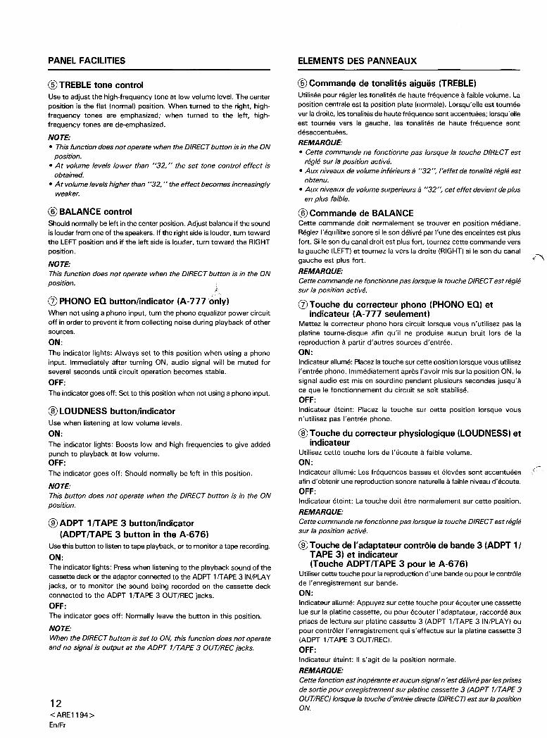
[FRONT PANEL]Illustration shows model A-777.
Model A-676 is not equipped with (j) and @.
I ELEMENTS DES PANNEAUX
[PANNEAU AVANT]
L'iIIustration represente Ie modele A- 777.Modele A-676 n'est pas equipe de (j) ni de @.
CD POWER switch/indicatorPress to turn power to the unit ON and OFF.When the power is ON, the indicator lights.
@ PHONES jackWhen using headphones, insert the plug into this jack.
@ SPEAKERS selector switchUse this switch to listen to the speaker systems connected toSPEAKERS terminals.
OFF:
Released position: No sound is heard from the speaker systems. Setto this position when listening with headphones.
A:
For reproduction of sound with the speaker system connected to theSPEAKERS A terminals.
B:
For reproduction of sound with the speaker system connected to theSPEAKERS B terminals.
A + B:
For reproduction of sound with the speaker systems connected toSPEAKERS A and B terminals.
@ BASS tone controkUse to adjust the low-frequency tone at low volume level. The centerposition is the flat (normal) position. When turned to the right, lowfrequency tones are emphasized; when turned to the left, low-frequencytones are de-emphasized.
NOTE:
• This function does not operate when the DIRECT button is in the ONposition .
• At volume levels lower than "32," the set tone control effect isobtained.
• At volume levels higher than "32," the effect becomes increasinglyweaker.
10<ARE1194>
EnlFr
* A-676 ADPTITAPE 3A-777 ADPT 1ITAPE 3
CD Interrupteur/indicateur d'alimentation (POWER)Appuyer sur cet interrupteur pour mettre I'appareil sous tension (ON)et hors circuit (OFF).
Quand I'appareil est sous tension, Ie temoin s'allume.
@Jack de casque (PHONES)Lors de I'utilisation d'un casque, inserer sa fiche dans ce jack.
@ Selecteur des enceintes (SPEAKERS)Utiliser ce selecteur pour ecouter Ie systeme d'enceintes raccorde auxbornes SPEAKERS.
Desactive (OFF):
Position reliichee: Aucun son n'est entendu par lesysteme d'enceintes.Le regler sur cette position pour une ecoute avec un casque.A:Pour une reproduction sonore sur les enceintes raccordees aux bornespour enceintes (SPEAKERS) A.B:
Pour une reproduction sonore sur les enceintes raccordees aux bornespour enceintes (SPEAKERS) B.A + B:
Pour une reproduction sonore sur les enceintes raccordees aux bornespour enceintes (SPEAKERS) A et B.
@ Commande de tonalites graves (BASS)Utilisee pour regler les tonalites de basse frequence a faible volume. Laposition centrale est la position plate (normal). Lorsqu'elle est tourneevers la droite, les tonalites de basse frequence sont accentuees;
lorsqu'elle est tournee vers la gauche, les tonalites de basse frequencesont desaccentuees.
REMARQUE:
• Cette commande ne fonctionne pas lorsque la touche DIRECT estregIe sur la position active.
• Aux niveaux de volume inferieurs a "32", I'effet de tonalite regIe estobtenu.
• Aux niveaux de volume surperieurs a "32", cet effet devient de plusen plus faible.
PANEL FACILITIES
® TREBLE tone controlUse to adjust the high-frequency tone at low volume level. The center
position is the flat (normal) position. When turned to the right, highfrequency tones are emphasized; when turned to the left, highfrequency tones are de-emphasized.
NOTE:
• This function does not operate when the DIRECT button is in the ONposition.
• At volume levels lower than "32," the set tone control effect isobtained.
• At volume levels higher than "32," the effect becomes increasinglyweaker.
® BALANCE controlShould normally be left in the center position. Adjust balance if the soundis louder from one of the speakers. If the right side is louder, turn towardthe LEFT position and if the left side is louder, turn toward the RIGHTposition.
NOTE:
This function does not operate when the DIRECT button is in the ONposition.
rJ) PHONO EQ button/indicator (A-777 only)When not using a phono input, turn the phono equalizer power circuitoff in order to prevent it from collecting noise during playback of othersources.
ON:
The indicator lights: Always set to this position when using a phonoinput. Immediately after turning ON, audio signal will be muted forseveral seconds until circuit operation becomes stable.
OFF:
The indicator goes off: Set to this position when not using a phono input.
® LOUDNESS button/indicatorUse when listening at low volume levels.
ON:
The indicator lights: Boosts low and high frequencies to give addedpunch to playback at low volume.OFF:
The indicator goes off: Should normally be left in this position.
NOTE:
This button does not operate when the DIRECT button is in the ONposition.
® ADPT 1IT APE 3 button/indicator(ADPT IT APE 3 button in the A-676)
Use this button to listen to tape playback, or to monitor a tape recording.
ON:
The indicator lights: Press when listening to the playback sound of thecassette deck or the adaptor connected to the ADPT 1rrAPE 3 IN/PLAY
jacks, or to monitor the sound being recorded on the cassette deckconnected to the ADPT 1rrAPE 3 OUT/REC jacks.OFF:
The indicator goes off: Normally leave the button in this position.
NOTE:
When the DIRECT button is set to ON, this function does not operateand no signal is output at the ADPT 1/TAPE 3 OUT/REC jacks.
12<ARE1194>
En/Fr
ELEMENTS DES PANNEAUX
® Commande de tonalites aigues (TREBLE)Utilisee pour regler les tonalites de haute frequence a faible volume. Laposition centrale est la position plate (normale). Lorsqu'elle est tourneever la droite, les tonalites de haute frequence sont accentuees; lorsqu' elleest tournee vers la gauche, les tonalites de haute frequence sontdesaccentuees.
REMAROUE:
• Cette commande ne fonctionne pas lorsque la touche DIRECT estregie sur la position active.
• Aux niveaux de volume inferieurs a "32 ", I'effet de tonalite regie estobtenu.
• Aux niveaux de volume surperieurs a "32", cet effet devient de plusen plus faible.
® Commande de BALANCECette commande doit normalement se trouver en position mediane.Reglez I'equilibre sonore si Ie son delivre par I'une des enceintes est plusfort. Si Ie son du canal droit est plus fort, tournez cette commande vers
la gauche (LEFT) et tournez-Ia vers la droite (RIGHT) si Ie son du canalgauche est plus fort. ~."",,\
REMAROUE:
Cette commande ne fonctionne pas lorsque la touche DIRECT est regiesur la position active.
rJ) Touche du correcteur phono (PHONO EQ) etindicateur (A-777 seulement)
Mettez Ie correcteur phono hors circuit lorsque vous n'utilisez pas laplatine tourne-disque afin qu'il ne produise aucun bruit lors de lareproduction a partir d'autres sources d'entree.ON:Indicateur allume: P1acezla touche sur cette position lorsque vous utilisezI'entree phono. Immediatement apres I'avoir mis sur la position ON, Iesignal audio est mis en sourdine pendant plusieurs secondes jusqu'ace que Ie fonctionnement du circuit se soit stabilise.OFF:
Indicateur eteint: Placez la touche sur cette position lorsque vousn'utilisez pas I'entree phono.
® Touche du correcteur physiologique (LOUDNESS) etindicateur
Utilisez cette touche lors de I'ecoute a faible volume.
ON:Indicateur allume: Les frequences basses et elevees sont accentueesafin d'obtenir une reproduction sonore naturelle a faible niveau d'ecoute.OFF:
Indicateur eteint: La touche doit etre normalement sur cette position.
REMAROUE:
Cette commande ne fonctionne pas lorsque la touche DIRECT est regiesur la position active.
® Touche de I'adaptateur controle de bande 3 (ADPT 1/TAPE 3) et indicateur(Touche ADPTITAPE 3 pour Ie A-676)
Utiliser cette touche pour la reproduction d'une bande ou pour Ie contr61ede I'enregistrement sur bande.ON:Indicateur allume: Appuyez sur cette touche pour ecouter une cassettelue sur la platine cassette, ou pour ecouter I'adaptateur, raccorde auxprises de lecture sur platine cassette 3 (ADPT 1rrAPE 3 IN/PLA Y) oupour contr61er I'enregistrement qui s'effectue sur la platine cassette 3(ADPT 1rrAPE 3 OUT/REC).
OFF:
Indicateur eteint: II s'agit de la position norma Ie.
REMAROUE:
Cette fonction est inoperante et aucun signal n' est delivre par les prisesde sortie pour enregistrement sur platine cassette 3 (ADPT 1/T APE 3OUT/REC) lorsque la touche d'entree directe (DIRECT) est sur la positionON.
PANEL FACILITIES
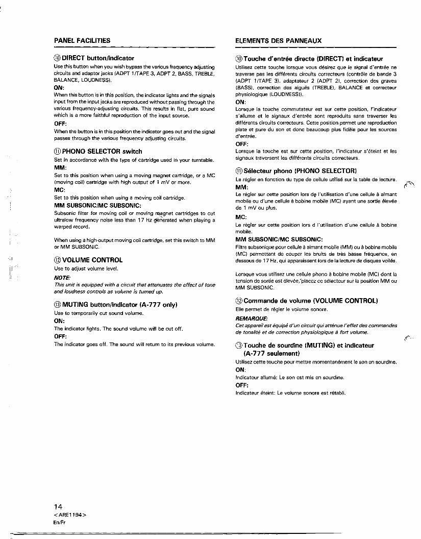
@ DIRECT button/indicatorUse this button when you wish bypass the various frequency adjustingcircuits and adaptor jacks (ADPT 1fTAPE 3, ADPT 2, BASS, TREBLE,BALANCE, LOUDNESS).
ON:
When this button is in this position, the indicator lights and the signalsinput from the input jacks are reproduced without passing through thevarious frequency-adjusting circuits. This results in flat, pure soundwhich is a more faithful reproduction of the input source.
OFF:
When the button is in this position the indicator goes out and the signalpasses through the various frequency adjusting circuits.
® PHONO SELECTOR switchSet in accordance with the type of cartridge used in your turntable.
MM:Set to this position when using a moving magnet cartridge, or a MC(moving coil) cartridge with high output of 1 mV or more.
MC:
Set to this position when using a moving coil cartridge.
MM SUBSONIC/MC SUBSONIC:
Subsonic filter for moving coil or moving n;t9gnet cartridges to cutultra low frequency noise less than 17Hz g'en'erated when playing awarped record.
When using a high-output moving coil cartridge, set this switch to MMor MM SUBSONIC.
@ VOLUME CONTROLUse to adjust volume level.
NOTE:
This unit is equipped with a circuit that attenuates the effect of toneand loudness controls as volume is turned up.
@MUTING button/indicator (A-777 only)Use to temporarily cut sound volume.
ON:
The indicator lights. The sound volume will be cut off.
OFF:
The indicator goes off. The sound will return to its previous volume.
14<ARE1194>
En/Fr
ELEMENTS DES PANNEAUX
@ Touche d'entree directe (DIRECT) et indicateurUtilisez cette touche lorsque vous desirez que Ie signal d'entree netraverse pas les differents circuits correcteurs (controle de bande 3(ADPT 1fT APE 3), adaptateur 2 (ADPT 2), correction des graves(BASS), correction des aigues (TREBLE), BALANCE et correcteurphysiologique (LOUDNESS)).
ON:Lorsque la touche commutateur est sur cette position, I'indicateurs'allume et Ie signaux d'entree sont reproduits sans traverser lesdifferents circuits correcteurs. Cette position permet une reproductionplate et pure du son et donc beaucoup plus fidele pour les sourcesd'entree.
OFF:Lorsque la touche est sur cette position, I'indicateur s' eteint et lessignaux traversent les differents circuits correcteurs.
® Selecteur phono (PHONO SELECTOR)Le regler en fonction du type de cellule utilise sur la table de lecture.
MM:Le regler sur cette position lors dfill'utilisation d'une cellule a aimantmobile ou d'une cellule a bobine mobile (MC) ayant une sortie eleveede 1 mV ou plus.
MC:
Le regler sur cette position lors d I'utilisation d'une cellule a bobinemobile.
MM SUBSONIC/MC SUBSONIC:
Filtre subsonique pour cellule a aimant mobile (MM) ou a bobine mobile(MC) permettant de couper les bruits de tres basse frequence, endessous de 17 Hz, qui apparaissent lors de la lecture de disques voiles.
Lorsque vous utilisez une cellule phono a bobine mobile (MC) dont latension de sortie est elevee:placez ce selecteur sur la position MM ouMM SUBSONIC.
@ Commande de volume (VOLUME CONTROL)Elle permet de regler Ie volume sonore.
REMARQUE:
Cet appareil est equipe d'un circuit qui attenue reffet des commandesde tonalite et de correction physiologique a fort volume.
@Touche de sourdine (MUTING) et indicateur(A-777 seulement)
Utilisez cette touche pour mettre momentanement Ie son en sourdine.
ON:Indicateur allume: Le son est mis en sourdine.
OFF:Indicateur eteint: Le volume sonore est retabli.
PANEL FACILITIES
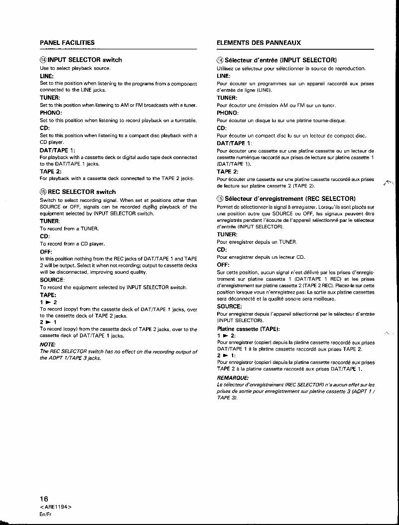
® INPUT SELECTOR switchUse to select playback source.
LINE:
Set to this position when listening to the programs from a componentconnected to the LINE jacks.
TUNER:
Set to this position when listening to AM or FM broadcasts with a tuner.
PHONO:
Set to this position when listening to record playback on a turntable.
CD:
Set to this position when listening to a compact disc playback with aCD player.
OAT/TAPE 1:For playback with a cassette deck or digital audio tape deck connectedto the DATITAPE 1 jacks.
TAPE 2:For playback with a cassette deck connected to the TAPE 2 jacks.
® REC SELECTOR switchSwitch to select recording signal. When set at f;lositions other thanSOURCE or OFF, signals can be recorded durihg playback of theequipment selected by INPUT SELECTOR switch.
TUNER:To record from a TUNER.
CD:
To record from a CD player.
OFF:
In this position nothing from the REC jacks of DA T IT APE 1 and TAPE2 will be output. Select it when not recording; output to cassette deckswill be disconnected, improving sound quality.
SOURCE:
To record the equipment selected by INPUT SELECTOR switch.
TAPE:1 ~ 2
To record (copy) from the cassette deck of DATITAPE 1 jacks, overto the cassette deck of TAPE 2 jacks.2 ~ 1To record (copy) from the cassette deck of TAPE 2 jacks, over to thecassette deck of DATITAPE 1 jacks.
NOTE:
The REC SELECTOR switch has no effect on the recording output ofthe ADPT 1/TAPE 3jacks.
16<ARE1194>
En/Fr
ELEMENTS DES PANNEAUX
® Selecteur d'entree (INPUT SELECTOR)Utilisez ce selecteur pour selectionner la source de reproduction.
LINE:
Pour ecouter un programmes sur un appareil raccorde aux prisesd'entree de Iigne (LINE).
TUNER:Pour ecouter une emission AM ou FM sur un tuner.
PHONO:
Pour ecouter un disque lu sur une platine tourne-disque.
CD:
Pour ecouter un compact disc lu sur un lecteur de compact disc.
OAT/TAPE 1:
Pour ecouter une cassette sur une platine cassette ou un lecteur decassette numerique raccorde aux prises de lecture sur platine cassette 1(DATITAPE 1).
TAPE 2:
Pour ecouter une cassette sur une platine cassette raccorde aux prisesde lecture sur platine cassette 2 (TAPE 2).
® Selecteur d'enregistrement (REC SELECTOR)Permet de selectionner la signal a enregistrer. Lorsqu'i1s sont places surune position autre que SOURCE ou OFF, les signaux peuvent etreenregistres pendant I'ecoute de I'appareil selectionne par Ie selecteurd'entree (INPUT SELECTOR).
TUNER:
Pour enregistrer depuis un TUNER.
CD:
Pour enregistrer depuis un lecteur CD.
OFF:
Sur cette position, aucun signal n'est delivre par les prises d'enregistrement sur platine cassette 1 (DAT IT APE 1 REC) et les prisesd'enregistrement sur platine cassette 2 (TAPE 2 REC). Placez-Iesur cetteposition lorsque vous n' enregistrez pas: La sortie aux platine cassettessera deconnecte et la qualite sonore sera meilleure.
SOURCE:
Pour enregistrer depuis I'appareil selectionne par Ie selecteur d'entree(INPUT SELECTOR).
Platine cassette (TAPE):1 ~ 2:Pour enregistrer (copier) depuis la platine cassette raccorde aux prisesDATITAPE 1 ala platine cassette raccorde aux prises TAPE 2.2 ~ 1:Pour enregistrer (copier) depuis la platine cassette raccorde aux prisesTAPE 2 a la platine cassette raccorde aux prises DA T IT APE 1.
REMARQUE'
Le se/ecteur d' enregistrement (REC SELECTOR) n 'a aucun effet sur /esprises de sortie pour enregistrement sur p/atine cassette 3 (ADPT 1/TAPE 3).
PANEL FACILITIES
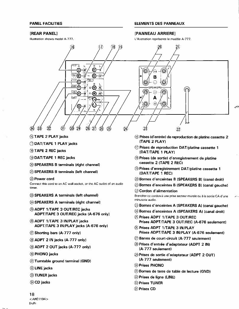
[REAR PANEL]Illustration shows model A-777.
ELEMENTS DES PANNEAUX
[PANNEAU ARRIERE]
L'illustration repn3sente Ie modele A-777.
@ TAPE 2 PLAY jacks
@ DAT/TAPE 1 PLAY jacks
@ TAPE 2 REC jacks
® DATIT APE 1 REC jacks
® SPEAKERS B terminals (right channell
® SPEAKERS B terminals (left channell
@PowercordConnect this cord to an AC wall socket, or the AC outlet of an audiotimer.
® SPEAKERS A terminals (left channell
@ SPEAKERS A terminals (right channell
@ ADPT 11TAPE 3 OUT /REC jacksADPTITAPE 3 OUT/REC jacks (A-676 only)
@ ADPT 11TAPE 3 IN/PLAY jacksADPT/TAPE 3 IN/PLAY jacks (A-676 only)
® Shorting bars (A-777 only)
@ADPT 2 IN jacks (A-777 only)
® ADPT 2 OUT jacks (A-777 only)
@) PHONO jacks
® Turntable ground terminal (GND)
®L1NE jacks
@ TUNER jacks
@CDjacks
18<ARE1194>
En/Fr
@Prises (d'entree) de reproduction de platine cassette 2(TAPE 2 PLAY)
@ Prises de reproduction DAT/platine cassette 1(DATITAPE 1 PLAY)
@Prises (de sortie) d'enregistrement de platinecassette 2 (TAPE 2 REC)
® Prises d' enregistrement DAT/platine cassette 1(DATITAPE 1 REC)
® Bornes d'enceintes B (SPEAKERS B) (canal droit)
® Bornes d'enceintes B (SPEAKERS B) (canal gauche)
@ Cordon d' alimentationBrancher ce cordon a une prise secteur murale ou a la sortie CA d'une ...."minuterie audio.
® Bornes d'enceintes A (SPEAKERS A) (canal gauche)
@Bornes d'enceintes A (SPEAKERS A) (canal droit)
@ Prises ADPT 1/TAPE 3 OUT/RECPrises ADPTITAPE 3 OUT/REC (A-676 seulement)
@PrisesADPT 1/TAPE 3 IN/PLAYPrises ADPT/TAPE 3 IN/PLAY (A-676 seulement)
® Barres de court-circuit (A-777 seulement)
@Prises d'entree d'adaptateur (ADPT 2 IN)(A-777 seulement)
® Prises de sortie d'adaptateur (ADPT 2 OUT)(A-777 seulement)
@) Prises PHONO
® Bornes de terre de table de lecture (GND)
® Prises de ligne (LINE)
@ Prises TUNER
@Prises CD
I OPERATIONS I I UTILISATION I
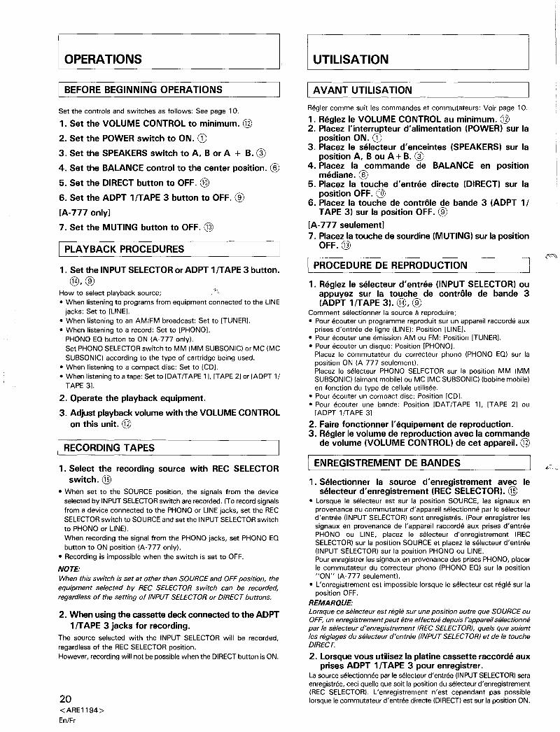
BEFORE BEGINNING OPERATIONS
Set the controls and switches as follows: See page 10.
1. Set the VOLUME CONTROL to minimum. @
2. Set the POWER switch to ON. CD
3. Set the SPEAKERS switch to A, B or A + B. @
4. Set the BALANCE control to the center position. ®5. Set the DIRECT button to OFF. ®6. Set the ADPT 1/TAPE 3 button to OFF. ®[A-777 only]
7. Set the MUTING button to OFF. @
I PLAYBACK PROCEDURES
1. Set the INPUT SELECTORor ADPT 1/TAPE 3 button.
@,®How to select playback source;• When listening to programs from equipment connected to the LINE
jacks: Set to [LINE].• When listening to an AM/FM broadcast: Set to [TUNER].• When listening to a record: Set to [PHONOJ.
PHONO EO button to ON (A-777 only).Set PHONO SELECTOR switch to MM (MM SUBSONIC) or MC (MC
SUBSONIC) according to the type of cartridge being used.• When listening to a compact disc: Set to [CD].• When listening to a tape: Set to [OAT ITAPE 11. [TAPE 2] or [ADPT 1I
TAPE 3].
2. Operate the playback equipment.
3. Adjust playbackvolume with the VOLUME CONTROLon this unit. @
RECORDING TAPES
1. Select the recording source with REC SELECTORswitch. ®
• When set to the SOURCE position, the signals from the deviceselected by INPUT SELECTOR switch are recorded. (To record signalsfrom a device connected to the PHONO or LINE jacks, set the RECSELECTOR switch to SOURCE and set the INPUT SELECTOR switch
to PHONO or LINE).
When recording the signal from the PHONO jacks, set PHONO EObutton to ON position (A-777 only).
• Recording is impossible when the switch is set to OFF.
NOTE:
When this switch is set at other than SOURCE and OFF position, theequipment selected by REC SELECTOR switch can be recorded,regardless of the setting of INPUT SELECTOR or DIRECT buttons.
2. When usingthe cassette deck connectedto the ADPT1/TAPE 3 jacks for recording.
The source selected with the INPUT SELECTOR will be recorded,
regardless of the REC SELECTOR position.However, recording will not be possible when the DIRECT button is ON.
20<ARE1194>
EnlFr
AVANT UTILISATION
Regier com me suit les commandes et commutateurs: Voir page 10.
1. Reglez Ie VOLUME CONTROL au minimum. @2. Placez l'interrupteur d'alimentation (POWER) sur la
position ON. CD3. Placez Ie selecteur d'enceintes (SPEAKERS) sur la
position A, B ou A + B. @4. Placez la commande de BALANCE en position
mediane. ®5. Placez la touche d'entree directe (DIRECT) sur la
position OFF. ®6. Placez la touche de contrale de bande 3 (ADPT 1/
TAPE 3) sur la position OFF. ®[A-777 seulement]7. Placez la touche de sourdine(MUTING) sur la position
OFF.@
~OCEDURE DE REPRODUCTION
1. Reglez Ie selecteur d'entree (INPUT SELECTOR) ouappuyez sur la touche de contrale de bande 3(ADPT 1/TAPE 3). @, ®
Comment selectionner la source a reproduire;• Pour ecouter un programme reproduit sur un appareil raccorde aux
prises d'entree de Iigne (LINE): Position [LINE].• Pour ecouter une emission AM ou FM: Position [TUNER].• Pour ecouter un disque: Position [PHONOl.
Placez Ie commutateur du correcteur phono (PHONO EO) sur laposition ON (A-777 seulement).Placez Ie selecteur PHONO SELECTOR sur la position MM (MMSUBSONIC) (aimant mobile) ou MC (MC SUBSONIC) (bobine mobile)en fonction du type de cellule utilisee.
• Pour ecouter un compact disc: Position [CDl.• Pour ecouter une bande: Position [DATITAPE 1], [TAPE 2] ou
[ADPT 1IT APE 3]
2. Faire fonctionner I'equipement de reproduction.3. Regier Ie volume de reproduction avec la commande
de volume (VOLUME CONTROL) de cet appareil. @
I ENREGISTREMENT DE BAN DES
1. Selectionner la source d'enregistrement avec Ieselecteur d'enregistrement (REC SELECTOR). ®
• Lorsque Ie selecteur est sur la position SOURCE, les signaux enprovenance du commutateur d'appareil selectionne par Ie selecteurd'entree (INPUT SELECTOR) sont enregistres. (Pour enregistrer lessignaux en provenance de I'appareil raccorde aux prises d'entreePHONO ou LINE, placez Ie selecteur d' enregistrement (REeSELECTOR) sur la position SOURCE et placez Ie selecteur d'entree(INPUT SELECTOR) sur la position PHONO au LINE.Pour enregistrer les signaux en provenance des prises PHONO, placerIe commutateur du correcteur phono (PHONO EO) sur la position"ON" (A-777 seulement).
• L'enregistrement est impossible lorsque Ie selecteur est regie sur laposition OFF.
REMARQUE:
Lorsque ce selecteur est regie sur une position autre que SOURCE ouOFF, un enregistrement peut etre effectue depuis /'apparei/ selectionnepar Ie selecteur d'enregistrement (REC SELECTOR), quels que soientles reglages du selecteur d'entree (INPUT SELECTOR) et de la toucheDIRECT.
2. Lorsquevous utilisez la platine cassette raccorde auxprises ADPT 1/TAPE 3 pour enregistrer.
La source selectionnee par Ie selecteur d'entree (INPUT SELECTOR) seraenregistree, ceci quelle que soit la position du selecteur d'enregistrement(REC SELECTOR). L'enregistrement n'est cependant pas possiblelorsque Ie commutateur d'entree directe (DIRECT) est sur la position ON.
OPERATIONS
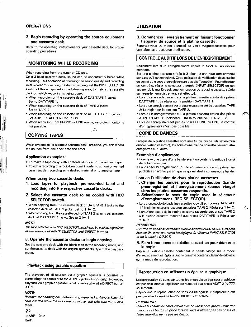
3. Begin recording by operating the source equipmentand cassette deck.
Refer to the operating instructions for your cassette deck for properoperating procedures.
I MONITORING WHilE RECORDING
When recording from the tuner or CD only.On a 3-head cassette deck, sound can be concurrently heard whilerecording. This operation of checking the sound quality and recordinglevel is called "monitoring." When monitoring, set the INPUT SELECTORswitch of this equipment in the following way, to match the cassettedeck on which recording is being done.
• When recording on the cassette deck of DATfTAPE 1 jacks:Set to DATfTAPE 1.
• When recording on the cassette deck of TAPE 2 jacks:Set to TAPE 2.
• When recording on the cassette deck of ADPT 1fT APE 3 jacks:Set ADPT 1fT APE 3 button to ON.
• When recording from PHONO or LINE source, recording monitor is
not possible. k.
I COPYING TAPES
When two decks (or a double cassette deck) are used, you can recordthe sounds from one deck onto the other.
Application examples:• To make a tape copy with contents identical to the original tape.• To edit a recording of a radio broadcast in order to cut out unwanted
commercials, recording only desired material onto another tape.
When using two cassette decks1. Load tapes for playback (pre-recorded tape) and
recording into the respective cassette decks.
2. Select the cassette deck to be copied with RECSELECTOR switch.
• When copying from the cassette deck of DATfTAPE 1 jacks to thecassette deck of TAPE 2 jacks: Set to 1 ~ 2.
• When copying from the cassette deck of TAPE 2 jacks to the cassettedeck of DA T fT APE 1 jacks: Set to 2 ~ 1.
NOTE:
The tape selected with REC SELECTORswitch can be copied, regardlessof the settings of INPUT SELECTOR and DIRECT buttons.
3. Operate the cassette decks to begin copying.Set the cassette deck with the blank tape to the recording mode, andset the cassette deck with the original (playback) tape to the playbackmode.
[ Playback using graphic equalizer
The playback of all sources via a graphic equalizer is possible byconnecting the equalizer to the ADPT 2 jacks (A-777 only). However,playback via a graphic equalizer is not possible when the DIRECT buttonis ON.
NOTE:
Remove the shorting bars before using these jacks. Always keep thebars inserted while the jacks are not in use, and take care not to losethem.
22<ARE1194>
En/Fr
UTILISATION
3. Commencer I'p-nregistrementen faisant fonctionnerI'appareil de source et la platine cassette.
Reportez-vous au mode d'emploi de votre magnetocassette pourconnaitre les procedures d'utilisation.
I caNTRalE AUDITIF LaRS DE l'ENREGISTREMENT I
Seulement lors d'un enregistrement depuis Ie tuner ou un disquecompact.Sur une platine cassette stereo a 3 tetes, Ie son peut etre entendupendant qu'il est enregistre. Cette operation de verification de la qualitedu son et du niveau d'enregistrement s'applle "contrale". Pour effectuerun contrale, regler Ie selecteur d'entree (INPUT SELECTOR) de cetappareil de la maniere suivante, en fonction de la platine cassette stereosur laquelle I'enregistrement est effectue.• Lors d'un enregistrement sur la platine cassette stereo des prises
DATfTAPE 1: Le regler sur la position DATfTAPE 1.• Lors d'un enregistrement sur la platine cassette stereo des prises TAPE
2: Le regler sur la position TAPE 2.• Lors d'un enregistrement sur la platine cassette stereo des prises
ADPT 1fT APE 3: Enclencher (ON) la touche ADPT 1fT APE 3.
• Lors de I'enregistrement par les prises PHONO ou LINE, Ie contaled'enregisrement n'est pas possible.
I COPIE DE BANDES
Lorsque deux platine cassettes sont utilises (ou lors de I'utilisation d'unduoble platine cassette), les sons d'une platine cassette peuvent etreenregistres sur I'autre.
Exemples d'application:• Pour faire une copie d'une bande ayant un contenu identique a celui
de la bande original.• Pour editer I'enregistrement d'une emission afin de supprimer les
publicites en n'enregistrant que ce qui est desire sur une autre bande.
Lors de I'utilisation de deux platine cassettes1 . Charger les ban des pour la reproduction (bande
preenregistree) et I'enregistrement (bande vierge)dans les platine cassettes respectifs.
2. Selectionner Ie sens de co pie avec Ie selecteurd'enregistrement (REC SELECTOR).
• Lors d'une copie de la platine cassette raccorde aux bornes DATfTAPE1 ala platine cassette raccorde aux prises TAPE 2: Regier sur 1 ~ 2.
• Lors d'une copie de la platine cassette raccorde aux prises TAPE 2a la platine cassette raccorde aux prises DAT/TAPE 1: Regier sur2 ~ 1.
REMARQUE:
L 'entree de bande selectionnee avec Ie selecteur REC SELECTOR peutetre copiee, quels que soient les reglages du selecteur INPUT SELECTORet de la touche DIRECT.
3. Faire fonctionner les platine cassettes pour demarrerla copie.
Regier la platine cassette contenant la bande vierge sur Ie moded'enregistrement et regler la platine cassette contenant la bande originalesur Ie mode de reproduction.
I Reproduction en utilisant un egaliseur graphique
La reproduction de sons par toutes les prises via un egaliseur graphiqueest possible lorsque I'egaliseur est raccorde aux prises ADPT 2 (A-777seulement).
Cependant, la reproduction de sons via un egaliseur graphique n'estpas possible lorsque la touche DIERCT est activee.
REMARQUE:
Retirez les barres de court-circuit avant d'utiliser ces prises. Remettez
toujours ces barres en place lorsque vous n'utilisez pas ces prises etfaites attention de ne pas les egarer.
r
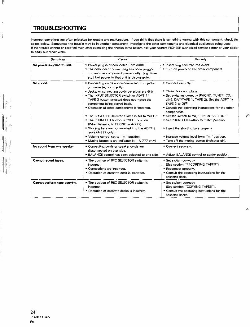
TROUBLESHOOTING
Incorrect operations are often mistaken for trouble and malfunctions. If you think that there is something wrong with this component, check thepoints below. Sometimes the trouble may lie in another component. Investigate the other components and electrical appliances being used.If the trouble cannot be rectified even after exercising the checks listed below, ask your nearest PIONEER authorized service cemer or your dealerto carry out repair work.
Symptom Cause Remedy
No power supplied to unit.
• Power plug is disconnected from outlet.• Insert plug securely into outlet.• The component power plug has been plugged
• Turn on power to the other component.into another component power outlet (e.g. timer, etc.) but power to that unit is disconnected.No sound.
• Connecting cords are disconnected from jacks,• Connect securely.or connected incorrectly. • Jacks, or connecting cords pin plugs are dirty.
• Clean jacks and plugs.• The INPUT SELECTOR switch or ADPT 1/
• Set switches correctly (PHONO, TUNER, CD,TAPE 3 button selected does not match the
LINE, DATITAPE 1, TAPE 2). Set the ADPT 1/
component being played back.
TAPE 3 to OFF.
• Operation of other components is incorrect.• Consult the operating instructions for the other
components.• The SPEAKERS selector switch is set to "OFF."• Set the switch to "A," "B" or "A + B."
• The PHONO EO button is "OFF" position• Set PHONO EO button to "ON" position.
(When listening to PHONO in A-777). • Shol1ing bars are not inserted into the ADPT 2• Insert the shorting bars properly.
jack§ (A-777 only). • Volume control set to "00" position.
• Increase volume level from "00" position.• Muting button is on (indicator lit). (A-777 only)
• Turn off the muting button (indicator off).
No sound from one speaker.
• Connecting cords or speaker cords are• Connect securely.disconnected on that side. • BALANCE control has been adjusted to one side.
• Adjust BALANCE control to center position.
Cannot record tapes.
• The position of REC SELECTOR switch is• Set switch correctlyincorrect.
(See section "RECORDING TAPES").• Connections are incorrect.
• Reconnect properly.• Operation of cassette deck is incorrect.
• Consult the operating instructions for thecassette deck.
Cannot perform tape copying.
• The position of REC SELECTOR switch is• Set switch correctlyincorrect.
(See section "COPYING TAPES").
• Operation of cassette decks is incorrect.• Consult the operating instructions for the
cassette decks.
24<ARE1194>
En
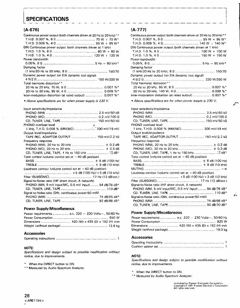
SPECIFICATIONS
[A-676]Continuous power output (both channels driven at 20 Hz to 20 kHz)"
T.H.D. 0.007 %, 8 n 70 W + 70 W'T.H.D. 0.009 %, 4 n 95 W + 95 W'
DIN Continuous power output (both channels driven at 1 kHz)T.H.D. 1.0 %,8 n 80 W + 80 WT.H.D. 1.0 %, 4 n 120 W + 120 W
Power bandwidth
0.05%, 8 n 5 Hz - 80 kHz'
Damping factor(1 kHz/20 Hz to 20 kHz). 8 n 150/70
Dynamic power output (on EIA dynamic test signal)4 n/2 n : 150 W/200 W
Total harmonic distortion"
20 Hz to 20 kHz, 70 W, 8 n 0.007 %'20 Hz to 20 kHz, 95 W, 4 n 0.009 %'
Inter-modulation distortion (at rated output) 0.007 %'
• Above specifications are for when power supply is 230 V.
Input sensitivity/impedancePHONO (MM) 2.5 mV/50 knPHONO (MC) 0.2 mV/100 n
CD, TUNER, LINE, TAPE 150 mV/50 knPHONO overload level .~
1 kHz, T.H.D. 0.008 % (MM/MC) / .. : 200 mV/19 mV
Output level/impedanceTAPE REC, ADAPTOR OUTPUT 150 mV/2.2 kn
Frequency responsePHONO (MM), 20 Hz to 20 kHz ± 0.2 dSPHONO (MC). 20 Hz to 20 kHz ± 0.3 dSCD, TUNER. LINE, TAPE, 1 Hz to 150 kHz :':~dS'
Tone control (volume control set at - 40 dS position)SASS ± 8 dS (100 Hz)TRESLE ± 8 dS (10kHz)
Loudness contour (volume control set at - 40 dS position)............................................ +5 dS (100 Hz)/+3 dS (10 kHz)Filter (SUSSONIC) 17 Hz (12 dS/oct.)
Signal-to-Noise ratio (IHF short circuit, A network)PHONO (MM, 5 mV input/MC, 0.5 mV input) 94 dS/76 dS'CD, TUNER. LINE, TAPE 110 dS'
Signal-to-Noise ratio (DIN, continuous power/50 mW)PHONO (MM) 74 dS/65 dS'
CD, TUNER, LINE, TAPE 92 dS/68 dS'
Power Supply/MiscellaneousPower requirements a.c. 220 - 230 Volts-, 50/60 HzPower Consumption 650 WDimensions 420 (W) x 435 (D) x 162 (H) mm
Weight (without package) 12.8 kg
Accessories
Operating instructions 1
NOTE:
Specifications and design subject to possible modification withoutnotice, due to improvements.
, When the DIRECT button to ON.
•• Measured by Audio Spectrum Analyzer.
28<ARE1194>
[A-777]Continuous power output (both channels driven at 20 Hz to 20 kHz)"
T.H.D. 0.007 %, 8 n 95 W + 95 W'T.H.D. 0.009 %, 4 n 140 W + 140 W'
DIN Continuous power output (both channels driven at 1 kHz)T.H.D. 1.0 %, 8 n 100 W + 100 WT.H.D. 1.0 %, 4 n 150 W + 150 W
Power bandwidth
0.05%,8 n 5 Hz - 80 kHz'
Damping factor(1 kHz/20 Hz to 20 kHz). 8 n 150/70
Dynamic power output (on EIA dynamic test signal)4 nl2 n 220 W/350 W
Total harmonic distortion"
20 Hz to 20 kHz, 95 W, 8 n 0.007 %'20 Hz to 20 kHz, 140 W, 4 n 0.009 %'
Inter-modulation distortion (at rated output) 0.007 %'
• Above specifications are for when power supply is 230 V.
Input sensitivity/impedancePHONO (MM) 2.5 mV/50 knPHONO (MC) 0.2 mV/100 n
CD, TUNER, LINE, TAPE 150 mV/50 knPHONO overload level
1 kHz, T.H.D. 0.008 % (MM/MC) 200 mV/19 mV
Output level/impedanceTAPE REC, ADAPTOR OUTPUT 150 mV/2.2 kn
Frequency responsePHONO (MM). 20 Hz to 20 kHz ± 0.2 dSPHONO (MC). 20 Hz to 20 kHz.. ± 0.3 dSCD, TUNER, LINE, TAPE, 1 Hz to 150 kHz :':~ dS'
Tone control (volume control set at - 40 dS position)SASS ± 8 dS (100 Hz)TRESLE ± 8 dS (10 kHz)
MUTING - 00
Loudness contour (volume control set at - 40 dS position)............................................ +5 dS (100 Hz)/+3 dS (10 kHz)Filter (SUSSONIC) 17 Hz (12 dS/oct.)
Signal-to-Noise ratio (lHF short circuit, A network)PHONO (MM, 5 mV input/MC, 0.5 mV input) 94 dS/76 dS'CD, TUNER. LINE, TAPE 110 dS'
Signal-to-Noise ratio (DIN, continuous power/50 mW)PHONO (MM) 74 dS/68 dS'
CD, TUNER, LINE, TAPE 92 dS/70 dS'
Power Supply/MiscellaneousPower requirements a.c. 220 - 230 Volts - , 50/60 HzPower Consumption 820 WDimensions 420 (W) x 435 (D) x 162 (H) mm
Weight (without package) 19.0 kg
Accessories
Operating instructions 1Cushion spacer set 1
NOTE:
Specifications and design subject to possible modification withoutnotice, due to improvements .
, When the DIRECT button to ON.
" Measured by Audio Spectrum Analyzer.
Published by Pioneer Electronic Corporation.Copyright © 1991 Pioneer Electronic Corporation.All rights reserved.


