9 Connectors for KNX/EIB Bus Coupler Units 243 Series EIDIKES AGORES/BMS/knx_connect_etc.pdf ·...
14
522 9 Material data: Material group I Insulating material Nylon 6.6 (PA 6.6) Flammability rating per UL 94 V0 Lower/Upper temperature limit –60°C / +105°C Clamping spring material Chrome-nickel spring steel (CrNi) Contact material Electrolytic copper (E Cu ) Contact plating tin-plated Approvals are available online at: www.wago.com For more technical information, see Section 11 243 Series accessories: Page: Connectors for KNX/EIB Bus Coupler Units 243 Series Conductor data: Connection technology PUSH WIRE ® Conductor size: solid Ø 4 x 0.6 – 0.8 mm or Ø 4 x 1.0 mm AWG 4 x 22 – 20 “sol.” or 4 x 18 “sol.” Strip length 5 – 6 mm / 0.20 – 0.24 in Technical data: Rating per IEC/EN 60664-1 Overvoltage category III III II Pollution degree 3 2 2 Rated voltage 250 V 320 V 630 V Rated surge voltage 4 kV 4 kV 4 kV Nominal current 6 A 6 A 6 A Approvals per UL/CSA Use group UL 1059 B C D Rated voltage – – – Nominal current UL – – – Nominal current CSA – – – ● Compact, 4-conductor KNX connector with PUSH WIRE ® connection ● Simple push-in termination for solid conductors ● 4-conductor entries allow devices to be replaced without disrupting the KNX bus connection
Transcript of 9 Connectors for KNX/EIB Bus Coupler Units 243 Series EIDIKES AGORES/BMS/knx_connect_etc.pdf ·...

522
9
Material data: Material group I Insulating material Nylon 6.6 (PA 6.6)
Flammability rating per UL 94 V0 Lower/Upper temperature limit –60°C / +105°C Clamping spring material Chrome-nickel spring steel (CrNi) Contact material Electrolytic copper (ECu) Contact plating tin-plated
Approvals are available online at: www.wago.com For more technical information, see Section 11
243 Series accessories: Page:
Connectors for KNX/EIB Bus Coupler Units 243 Series
Conductor data: Connection technology PUSH WIRE®
Conductor size: solid Ø 4 x 0.6 – 0.8 mm or Ø 4 x 1.0 mm AWG 4 x 22 – 20 “sol.” or 4 x 18 “sol.” Strip length 5 – 6 mm / 0.20 – 0.24 in
Technical data:
Rating per IEC/EN 60664-1 Overvoltage category III III II Pollution degree 3 2 2Rated voltage 250 V 320 V 630 V Rated surge voltage 4 kV 4 kV 4 kV Nominal current 6 A 6 A 6 AApprovals per UL/CSA Use group UL 1059 B C D Rated voltage – – –Nominal current UL – – –Nominal current CSA – – –
● Compact, 4-conductor KNX connector with PUSH WIRE® connection
● Simple push-in termination for solid conductors
● 4-conductor entries allow devices to be replaced without disrupting the KNX bus connection

9
523
9$
30°
>1,1<
>1<
30°
<______10 _____>
_2,5 <<_____10 _____>
<_______
11,5
_______>
<_____ 9 _____>
<_____ 9,1 _____>
3
3,4
3,2
The KNX bus system is the intelligent solution to simplify existing building installation control. Instead of many different conventional wiring styles, the KNX bus system offers a flexible general solution for all applications in the field of switching, controlling, measur-ing, monitoring and signaling. The decentralized KNX system works without a central unit. All components are active, intelligent modules. Only when using the different KNX components does the system become user-specific. For example, pairs of sensors/actua-tors control: – lighting – window blinds – heating/ventilation – energy management systems – information display/transmission Command data is transmitted via twisted-pair bus cable, which is connected to the sensors and actuators via WAGO modules. Sensors transmit commands as “telegrams” via the bus to the actuators, which record the information and act on the commands. To ensure that only fixed transmitters can trigger reactions in the fixed receivers, the “telegram” is provided with an address. The allocation (= addressing) is stipulated during programming. The bus system is divided into “lines” (segments). The bus lines can be wired at will acc. to the line, star or tree topol-ogy. WAGO connectors connect the different branches to one another in the junction boxes. If the installation will be extended later on, new compo-nents can be added to the existing bus without any prob-lems. If rooms, floors or buildings are to be used differently one day, the installations can remain unchanged. It is only necessary to reprogram the allocation of actuators to sensors.
Connectors for KNX/EIB Bus Coupler Units
Color Item No. Pack. Unit
Connectors for KNX bus coupler units, mounted, with test slot
dark gray and red 243-211 250
light gray and yellow 243-212 250
Connectors for KNX bus coupler units Description
Ø 0.6 – 0.8 mm AWG 22 – 20 “sol.” 320 V/ 4 kV/2 6 A

12503
12
Inserting a MICRO PUSH WIRE connector for junctionboxes into the carrier.
Removing a MICRO PUSH WIRE connector from thecarrier.
Example of residential (home) communication application
Quick fix mounting
Realizing MICRO PUSH WIRE connectors are ideal forDIN-rail mount panel applications, electrical installershave requested the ability to use them in distributionpanels. MICRO PUSH WIRE connectors provide easyconnections for smaller conductors used in low-currentapplications. They are well-suited to terminating telepho-ne-style conductors for connecting alarms, bells, door sen-sors, communication systems, etc.
The mounting carrier WAGO s Professional Solution. It isavailable with mounting slots for 4 or 6 connectors.
Depending on the number of conductors, each mountingslot can accommodate a 4- or 8-conductor MICRO con-nector. The connectors simply snap into the mountingslots and are removable, allowing conductors to beexchanged during changeover.
The carrier is designed for easy mounting directly to theDIN 35 rail, or to a panel, via the screw-mount flangesprovided. A large marking surface is provided for clearcircuit identification. This may be directly marked with afelt-tip pen, or via pre-printed self-adhesive marker strips.
Example of residential door bell application mounted on DIN 35 rail
Typical application in a terminal box for burglar alarm screw mount
�
Mounting Carrier for MICRO PUSH WIRE Connectorsfor DIN 35 Rail or Screw Mount, 243 Series

12504
�
The 243 Series of WAGO PUSH WIRE connectorscan be used in both communication and alarm sys-tems according to the VdS (German Association ofProperty Insurers) guidelines.
No general approval is given to push-wire connectors bythe VdS association. The connectors must be tested toge-ther with the different parts of the system.
The requirements for connectors are specified in the VdSguidelines for junction boxes (VdS 2116) in section 8.7:The junction box connectors must be designed to guaran-
tee a reliable and stable connection .
The verification of the fulfillment of these requirements isdocumented in the VDE test report No. 2574-1440-4031for the 243 Series of insulated PUSH WIRE connectors.
When using conductors with the same diameter,0.5 mm/AWG 24 or 1 mm/AWG 18 diameters arealso possible.
1
100 V = rated voltage1.5 kV = rated surge voltage
2 = pollution degree(also see Section 14)
2
Strip length, see packaging or instructions.3
MICRO PUSH WIRE Connectors for Junction Boxes 0.8 mm243 Series
$
Dimensions in mm
10
5,8
10
1
Dimensions in mm
10
5,8
1
18,4
1
��
MICRO PUSH WIRE connector for junction boxes,4-conductor connector
�
Item No.
243-304
Pack.Unit
1000 (10x100)
Color
light gray243-504 1000 (10x100)yellow
MICRO PUSH WIRE connector for junction boxes,4-conductor connector
�
Item No.
243-204
Pack.Unit
1000 (10x100)
Color
dark gray243-804 1000 (10x100)red
AWG 22 - 20 "s"0.6 - 0.8 mm "s"150 V, 7 AU100 V/1.5 kV/2150 V, 7 A2IN 6 A
L 5 - 6 mm / 0.22 in
Dimensions in mm
10
5,8
10
1
2
��
MICRO PUSH WIRE connector for junction boxes,8-conductor connector
�
Item No.
243-308
Pack.Unit
500 (10x50)
Color
light gray243-508 500 (10x50)yellow
MICRO PUSH WIRE connector for junction boxes,8-conductor connector
�
Item No.
243-208
Pack.Unit
500 (10x50)
Color
dark gray243-808 500 (10x50)red
AWG 22 - 20 "s"0.6 - 0.8 mm "s"150 V, 7 AU100 V/1.5 kV/2150 V, 7 A2IN 6 A
L 5 - 6 mm / 0.22 in
Dimensions in mm
10
5,8
1
18,4
For list of approvals and user guide, see pages 634 to 637.
1
2
3
1
2
3

12505
12
�
Quick fix mounting
Realizing MICRO PUSH WIRE connectors are ideal forDIN-rail mount panel applications, electrical installershave requested the ability to use them in distributionpanels. MICRO PUSH WIRE connectors provide easyconnections for smaller conductors used in low-currentapplications. They are well-suited to terminating telephone-style conductors for connecting alarms, bells, door sen-sors, communication systems, etc.
The mounting carrier WAGO s Professional Solution. It isavailable with mounting slots for 4 or 6 connectors.
Depending on the number of conductors, each mountingslot can accommodate a 4- or 8-conductor MICRO con-nector. The connectors simply snap into the mounting slotsand are removable, allowing conductors to be exchangedduring changeover.
The carrier is designed for easy mounting directly to theDIN 35 rail, or to a panel, via the screw-mount flangesprovided. A large marking surface is provided for clear cir-cuit identification. This may be directly marked with a felt-tip pen, or via pre-printed self-adhesive marker strips.
100 V = rated voltage1.5 kV = rated surge voltage
2 = pollution degree(also see Section 14)
1
Strip length, see packaging or instructions.2
MICRO PUSH WIRE Connectors for Junction Boxes 0.5 mmand Mounting Carriers for DIN 35 Rail or Screw Mount243 Series
$
Dimensions in mm
10
5,8
10
1
MICRO PUSH WIRE connector for junction boxes,4-conductor connector
�
Item No.
243-144
Pack.Unit
1000 (10x100)
Color
transparent�
AWG 26 - 24 "s"0.4 - 0.5 mm "s"100 V/1.5 kV/2IN 6 A
L 5 - 6 mm / 0.22 in
Mounting carrier,for 4 MICRO PUSH WIRE connectors
�
Item No.
243-112
Pack.Unit
50 (5x10)
Color
orange�
Mounting carrier,for 6 MICRO PUSH WIRE connectors
243-113 50 (5x10)orange
Item-Specific Accessories
Mounting carrier
Self-adhesive marking strips, plain,Height of marking strip: 7 mm, 6 self-adhesive strips per cardwhite 243-110 1
For list of approvals and user guide, see pages 634 to 637.
1
2

7188
Preparation
Handling WINSTA® KNX, 893 Series
Strain relief assembly
Snapwiredconnectorintostrainreliefhousing. Pressstrainrelieffirmlyonthecable. Pre-assembled KNX connector.
Todisconnect,openclampingunitviapurpleactuatorandpull out conductor.
Push conductors until they hit backstop.
Insert stripped conductor directly into the conductor entry .Priortotermination,pullthestrainreliefhousingoverthecable.
1. Striplength,outerinsulation:=23mm 2.Striplength= 9mm
Conductor termination
Conductor termination

7 189
7
<______ 47,5 _____>
< 14
,1>
<
14,1>
<______ 47,5 _____>
$
WINSTA® – Perfectly plugged!
0.8 mm Ø50 V/0.8 kV/3 IN 3 A
l 9 mm / 0.35 in 1 Approvals
0.8 mm Ø50 V/0.8 kV/3 IN 3 A
l 9 mm / 0.35 in 1 Approvals
Pluggable connectors, 2-pole, with spring clamp connection
Socket with strain relief housing, 5–7mmcablediameter2
green 893-1002 50
Special coding:
light gray 893-1022 50
Plug with strain relief housing, 5–7mmcablediameter2
green 893-1012 50
Special coding:
light gray 893-1032 50
1 For “International Certification Organizations” and “Approvals – User Guide,” see pages 240 to 243.
2 2Y(ST)2x(2x0.8)
green Coding E (1+ 2–) light gray Coding F (1+ 2–) For coding information, see pages 224 to 226.Fire load data available upon request.
Sockets and Plugs, 2-Pole WINSTA® KNX
Color Item No. Pack. Unit Color Item No. Pack. Unit Description
Info Dimensions

7190
<_____ 29,5 _____>
<_____ 28 _____>__>1,5
<_ 1
7,5 _>
<__ 19,6 __>
<__
19,6
__>
<_ 17,5 _>
<_____ 29,5 _____>
<_____ 28 _____>__>1,5
<_ 1
7,5 _>
<__ 19,6 __>
<__
19,6
__>
<_ 17,5 _>
<_____17,8_____>
<_____1
7,8 _____>
$0.8 mm Ø50 V/0.8 kV/3 IN 3 A
l 9 mm / 0.35 in 1 Approvals
0.8 mm Ø50 V/0.8 kV/3 IN 3 A
l 9 mm / 0.35 in 1 Approvals
Snap-in connectors, 2-pole, with spring clamp connection, T-distribution connectors
Socket, for KNX applications
green 893-2002 50
Special coding:
light gray 893-2022 50
Plug, for KNX applications
green 893-2012 50
Special coding:
light gray 893-2032 50
Snap-In Sockets and Plugs, 2-Pole WINSTA® KNX
Color Item No. Pack. Unit Color Item No. Pack. Unit
1 For “International Certification Organizations” and “Approvals – User Guide,” see pages 240 to 243.
green Coding E (1+ 2–) light gray Coding F (1+ 2–) For coding information, see pages 224 to 226.Fire load data available upon request.
Cutout dimensions
Plate thickness: 0.5 – 2 mm Cutout tolerance: + 0.1 mm
Description
Info Dimensions

7 191
7
<__
13 __>
<___ 1
5 ___>
<________
28,
9 __
______>
<________ 28,7 ________>
<__
13 __>
<___ 1
5 ___>
<________
28,
9 __
______>
<________ 28,7 ________>
50 V/0.8 kV/3 IN 3 A
1 Approvals
50 V/0.8 kV/3 IN 3 A
1 Approvals
T-distribution connector,1xplug/2xsocket, for KNX applications
green 893-1606 25
T-distribution connector,1xplug/2xsocket, withspecialcoding
light gray 893-1656 25
WINSTA® – Perfectly plugged!
Color Item No. Pack. Unit Color Item No. Pack. Unit
T-Distribution Connectors, 2-Pole
Dimensions
“Flyingleads”usingaT-distributionconnector

7192
<>
<>
14,1
14,1
<____________________________________ L _____________________________________>
<______ 47,5 ______> <______ 47,5 ______>
<>
14,1
<____________________________________ L _____________________________________>
<______ 47,5 ______> > <9<____23____>
<>
14,1
<____________________________________ L _____________________________________>
<______ 47,5 ______> > <9<____23____>
PVC UNITRONIC BUS EIB 2x2x0.8
50 V/0.8 kV/3 IN 3 A
1 Approvals
Coding E, for KNX applications PVC
1 m 894-8992/033-106
3 m 894-8992/033-306
5 m 894-8992/033-506
Length Item No.
Coding E, for KNX applications PVC
1 m 894-8992/133-106
3 m 894-8992/133-306
5 m 894-8992/133-506
Length Item No.
Coding E, for KNX applications PVC
1 m 894-8992/233-106
3 m 894-8992/233-306
5 m 894-8992/233-506
Length Item No.
Interconnecting cable, socket – plug
Connecting cable, socket – free end
Connecting cable, plug – free end
Info
1 For “International Certification Organizations” and “Approvals – User Guide,” see pages 240 to 243.
For halogen-free cables, please contact factory.
2 Cable core assignment, coding F: yellow 1+
white 2–
green Coding E (1+ 2–) light gray Coding F (1+ 2–) For coding information, see pages 224 to 226.Fire load data available upon request.
Cable Assemblies, 2 x 0.8 mm ØWINSTA® KNX
1+ 2–
2– 1+

8 195
8
8%
WINSTA® – Perfectly plugged!
772 Series IDC Modules for Flat Cables 5 x 2.5 mm² / 5 x 4 mm² / 5 x 2.5 mm² + 2 x 1.5 mm² – Supply Module 198 – Tap-Off Modules, WINSTA® MIDI Connectors 199
896 Series IDC Modules for 3 x 2.5 mm² Flat Cable – Supply and Tap-Off Modules 210,211
895 Series POWERBLOCK 10 for 5 x 10 mm² Flat Cable – Supply and Tap-Off Modules 212,213
895 Series POWERBLOCK 16 for 5 x 16 mm² Flat Cable – Supply and Tap-Off Modules 214,215
893 Series IDC Modules for Flat Cables 5 x 2.5 mm² + 2 x 1.5 mm² / 2 x 1.5 mm² – Supply Module (KNX and Special Coding) 202,206 – Tap-Off Modules (KNX and Special Coding) 203,207
for Flat Cables up to 16 mm² WINSTA® IDC
897 Series Flat Cables 2 x 1.5 mm² 208Flat Cables 5 x 2.5 mm² 200Flat Cables 5 x 4 mm² 201Flat Cables 5 x 2.5 mm² + 5 x 1.5 mm2 201,204
Note: -Installationconnectorsaredesignedforconnectionanddisconnectionwhilenotunderload. -Thereisnohazard-inducinginterchangeabilitywithsystemsbasedonIEC60309,IEC60320,
IEC60906andwithnationalconnectorandsocketsystems. -Compliancewiththestandards(IEC61535)doesnotguaranteehazard-avoiding,non-interchange-
abilitywithinstallationconnectorsystemsfromvariousmanufacturers. -Installationconnectorsystemsarenotasubstituteforresidentialconnector/socketsystems.
- WINSTA® IDC connectors are not intended for installation in open or easily accessible areas.

8 203
8
<_____ 39,4 ____>
<__
25 __>
<______ 44 ______> <_____ 39,4 ____>
<__
25 __>
<______ 44 ______>
%50 V/0.8 kV/3 IN 3 A
1 Approvals
50 V/0.8 kV/3 IN 3 A
1 Approvals
Tap-off module,2-pole, forconnectorsandcableassemblies, codingE,KNX, 1 Nm tightening torque
green 893-262 25
For flat cables, seepage204
Tap-off module,2-pole, forconnectorsandcableassemblies, codingF, 1 Nm tightening torque
light gray 893-269 25
For flat cables, seepage204
WINSTA® – Perfectly plugged!
893 Series Tap-Off Modules, 2-Pole, for 7-Core Flat Cable
Color Item No. Pack. Unit Color Item No. Pack. Unit
Contactismadewiththeflatcablebytighteningthescrews. Observe 1 Nm of tightening torque!
Snapping on transparent protective cover.
Connecting a cable assembly.
TheIDCmodulecanonlybemountedifthetwocodingscorrespond to each other. ShouldtheIDCmodulejamduringmounting,turnthemoduleby180°andremountit,flushwiththebase.
Dimensions
8206
<___ 17,7 ___>
<_____ 2
3,45
_____>
<_________ 36,8 __________>
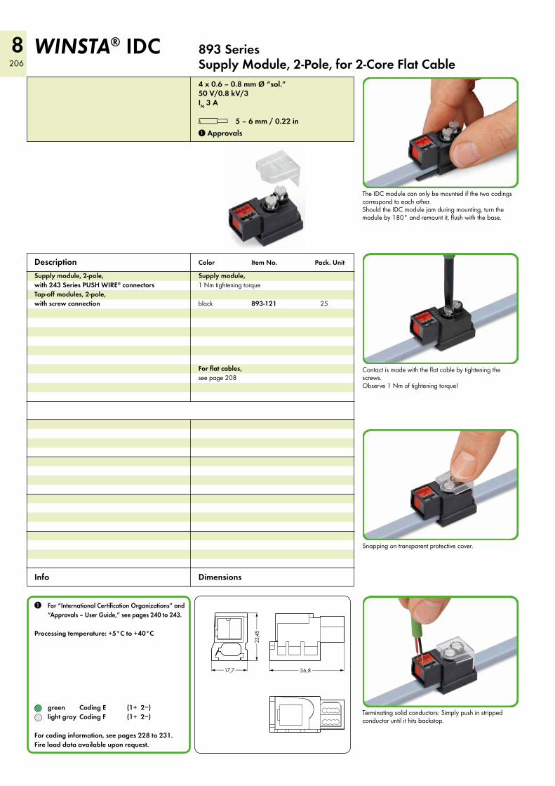
4 x 0.6 – 0.8 mm Ø “sol.”50 V/0.8 kV/3IN 3 A
l 5 – 6 mm / 0.22 in 1 Approvals
Supply module, 2-pole, with 243 Series PUSH WIRE® connectors Tap-off modules, 2-pole, with screw connection
Supply module, 1 Nm tightening torque
black 893-121 25
For flat cables, seepage208
Description
893 Series Supply Module, 2-Pole, for 2-Core Flat Cable
WINSTA® IDC
Color Item No. Pack. Unit
1 For “International Certification Organizations” and “Approvals – User Guide,” see pages 240 to 243.
Processing temperature: +5°C to +40°C
green Coding E (1+ 2–) light gray Coding F (1+ 2–) For coding information, see pages 228 to 231.Fire load data available upon request.
Contactismadewiththeflatcablebytighteningthescrews. Observe 1 Nm of tightening torque!
Snapping on transparent protective cover.
Terminating solid conductors: Simply push in stripped conductor until it hits backstop.
TheIDCmodulecanonlybemountedifthetwocodingscorrespond to each other. ShouldtheIDCmodulejamduringmounting,turnthemoduleby180°andremountit,flushwiththebase.
Info Dimensions

8 207
8
<__17,7__>
<___2
3,3___>
<__________ 46,7 __________> <__17,7__>
<___2
3,3___>
<__________ 46,7 __________>
%50 V/0.8 kV/3 IN 3 A
1 Approvals
50 V/0.8 kV/3 IN 3 A
1 Approvals
Tap-off module,2-pole, forconnectorsandcableassemblies,KNX, 1 Nm tightening torque
green 893-122 50
For flat cables, seepage208
Tap-off module,2-pole, forconnectorsandcableassemblies, 1 Nm tightening torque
light gray 893-129 50
For flat cables, seepage208
WINSTA® – Perfectly plugged!
893 Series Tap-Off Modules, 2-Pole, for 2-Core Flat Cable
Color Item No. Pack. Unit Color Item No. Pack. Unit
Contactismadewiththeflatcablebytighteningthescrews. Observe 1 Nm of tightening torque!
Snapping on transparent protective cover.
Connecting a cable assembly.
TheIDCmodulecanonlybemountedifthetwocodingscorrespond to each other. ShouldtheIDCmodulejamduringmounting,turnthemoduleby180°andremountit,flushwiththebase.
Dimensions